Extrinsic self-calibration of an operational mobile LiDAR ...
XIX IMEKO World Congress Fundamental and Applied Metrology
September 6−11, 2009, Lisbon, Portugal
EXTRINSIC PARAMETERS CALIBRATION OF A STRUCTURED LIGHT
SYSTEM VIA PLANAR HOMOGRAPHY BASED ON A REFERENCE SOLID
Enrico Marcuzzi 1, Giorgio Parzianello 2, Massimiliano Tordi 3, Massimo Bartolozzi 4, Massimo Lunardelli 5, Antonio Selmo 6, Luca Baglivo 7, Stefano Debei 8, Mariolino De Cecco 9
1 Cisas “G. Colombo”, Center Of Studies And Activities For Space, University of Padova, Italy,
[email protected] 2 Dep. Of Mechanical and Structural Engineering, Un. of Trento, Italy, [email protected]
3 Space Light SRL, Rovigo, Italy, [email protected] 4 Space Light SRL, Rovigo, Italy, [email protected]
5 Dep. Of Mechanical and Structural Engineering, Un. of Trento, [email protected] 6 Dep of Information Engineering, Un. of Padova, Italy, [email protected]
7 Cisas “G. Colombo”, Center Of Studies And Activities For Space, Un. of Padova, Italy, [email protected] 8 Cisas “G. Colombo”, Center Of Studies And Activities For Space, Un. of Padova, Italy, [email protected]
9 Dep. Of Mechanical and Structural Engineering, University of Trento, Italy, [email protected] Abstract − Structured light systems are widely used for
three-dimensional shape reconstruction. The accuracy of the vision system parameters is of paramount importance for the accuracy of the 3D reconstruction. Often the extrinsic parameters change over time due to environmental conditions, in order to compensate for structured light parameters change, a self-recalibration method based on planar homography is proposed in this paper. The method uses the planar homography of corresponding points in two camera views to identify the relative position and orientation between the two cameras: one is the “real” camera, while the other is a reference solid considered as a “pseudo-camera”. The laser plane of the structured light vision system is the constraining plane for the two cameras corresponding points.
In order to assess the metrological quality of the method an evaluation of the accuracy of the 3D reconstruction is performed by a two step Monte Carlo simulation. In a first step it is estimated the extrinsic parameters accuracy obtained by self-recalibration. In a second step the intrinsic parameters accuracy and the extrinsic one previously computed are used to evaluate the accuracy of 3D shape reconstruction. In the final version of the paper, the overall accuracy will be verified experimentally by a proper calibration setup.
Keywords: structured light vision system, planar homography, accuracy estimation
1. INTRODUCTION
The estimation of the camera’s relative pose parameters, known as the extrinsic parameters calibration, is one of the main issues for the 3D reconstruction of a scene from images. In the case of shape reconstruction using a single camera and structured light the relative pose between them
is of paramount importance for the accuracy of the 3D reconstruction. Applications range from the estimation of structure from motion, stereo vision, pose determination and so on, that are useful for object modelling, mobile robot navigation and localization, environments building, etc.
In general, the problem of camera calibration and 3D reconstruction can be approached in different ways, we concentrate on the pose problem using planar information in a semi-calibrated vision system. Specifically, we start from the plane-based homography method [3,4,5] to self-recalibrate the relative pose parameters between a camera and a laser plane. The novel method proposed for self-recalibration makes use of planar homography by defining the real camera, a reference solid as a pseudocamera, and the laser plane of the structured light vision system as the constraining plane for the two cameras corresponding points. Planar homography can be computed from the corresponding points of two views of a planar scene: in our setup, the first view comes from the real camera, the other from the reference solid prism that we model as a telecentric camera. The method can be applied during on-line measurement if the prism is in the camera field of view or if the whole structured light system is from time to time moved to have the solid inside the field of view. This last will be the test case discussed in the following.
Several researchers are involved in the study of 3D shape reconstruction and in particular to homograpy [7,8]. A self-recalibration method recently proposed [3] makes also use of plane-based homography. In this case they employ planar homography by using the real camera, the projector as a pseudocamera, and a plane.
To evaluate the shape accuracy reconstructed by the structured light vision system we propose a two-step method. First an evaluation of the recalibration parameters accuracy, then the shape reconstruction accuracy taking into account both the intrinsic parameters uncertainty obtained
from the initial camera-calibration given by the implemented method and extrinsic parameters uncertainty obtained in the previous step. Both steps are based on geometric modelling of the prism, of the object under study and of the vision system used in a Monte Carlo simulation.
The method has been applied for the erosion profile assessment of Hall effect thrusters and ion engines during thermal vacuum testing for space qualification. This is a test case where the laser plane relative pose with respect to the camera can change due to the thermal cycling variations and life cycles imposed during testing for space qualification.
2. THE STRUCTURED LIGHT VISION SYSTEM TO ASSESS THE EROSION PROFILE OF ELECTRIC
PROPULSION THRUSTERS
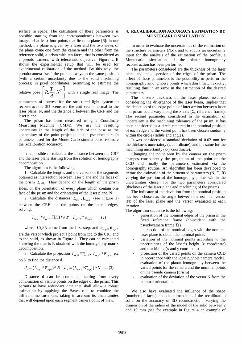
A structured light vision system is sketched in Figure 1. Extrinsic parameters self-calibration is aimed at the on-line estimation of the variations of N, the laser plane versor, and of d, the distance between camera reference frame and laser plane.
If the solid shape has to be measured, knowing the extrinsic parameters [N, d], which determinate the position of the laser plane, and the intrinsic ones which determine the CCD position with respect to the camera reference frame (CRF) ΣC it is possible to estimate by triangulation the points coordinates in 3D space [x, y, z]C with respect to the CRF. The geometry of the setup is shown in Figure 3.
If the solid shape is known with a good level of accuracy, it is possible to consider the correspondence of the CCD edge points [ri, ci]C seen by the CCD with the actual edge coordinates [ri, ci]S seen by the solid pseudocamera reference system, always constant since its model is pure telecentric. By this correspondence it is possible to compute N using planar homography, while d is computed knowing the reference solid geometry and its attitude with respect to the camera frame defined by the rotation matrix R between the two reference frames ΣC and ΣS, also estimated by planar homography.
N
Σc
eocp2
eocp1
e3L3
Σs
Laser Plane
CCD
de2L2
L1
e1
Locp2
Locp1
[ri, ci]c
[ri, ci]s
Figure 1: structured light vision system
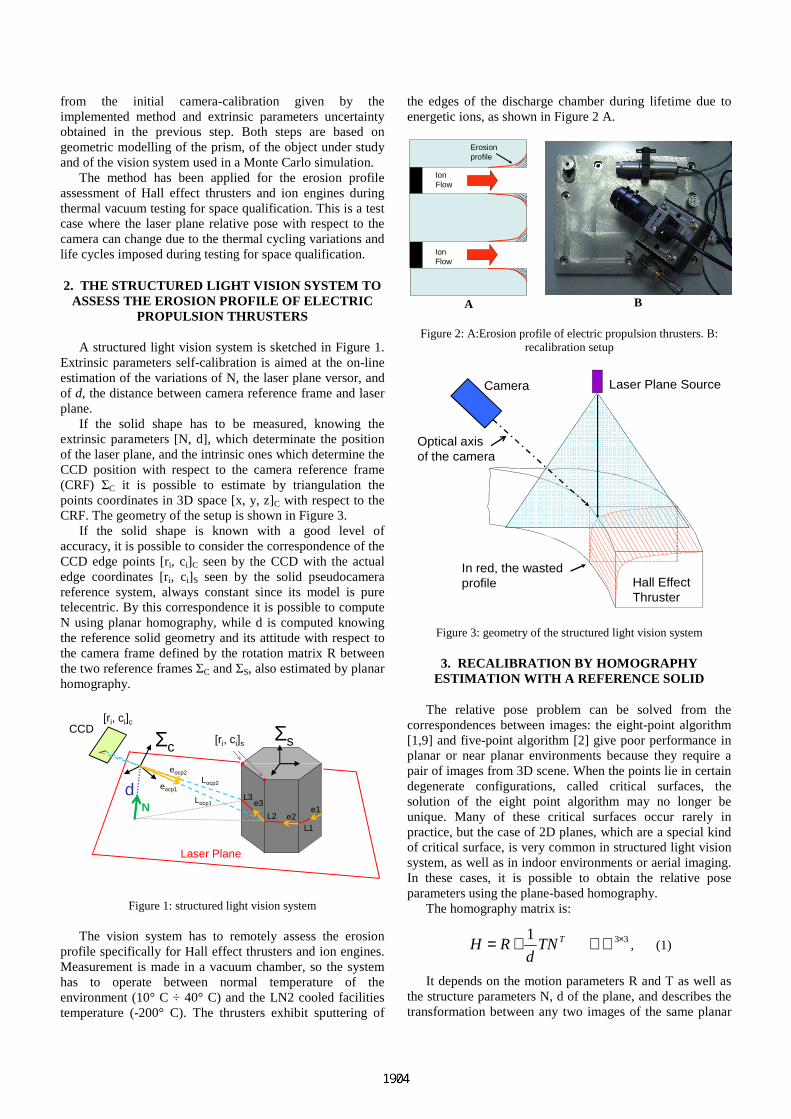
The vision system has to remotely assess the erosion profile specifically for Hall effect thrusters and ion engines. Measurement is made in a vacuum chamber, so the system has to operate between normal temperature of the environment (10° C ÷ 40° C) and the LN2 cooled facilities temperature (-200° C). The thrusters exhibit sputtering of
the edges of the discharge chamber during lifetime due to energetic ions, as shown in Figure 2 A.
IonFlow
Erosionprofile
IonFlow
A
B
Figure 2: A:Erosion profile of electric propulsion thrusters. B: recalibration setup
Laser Plane SourceCamera
Optical axisof the camera
Hall EffectThruster
In red, the wastedprofile
Figure 3: geometry of the structured light vision system
3. RECALIBRATION BY HOMOGRAPHY ESTIMATION WITH A REFERENCE SOLID
The relative pose problem can be solved from the correspondences between images: the eight-point algorithm [1,9] and five-point algorithm [2] give poor performance in planar or near planar environments because they require a pair of images from 3D scene. When the points lie in certain degenerate configurations, called critical surfaces, the solution of the eight point algorithm may no longer be unique. Many of these critical surfaces occur rarely in practice, but the case of 2D planes, which are a special kind of critical surface, is very common in structured light vision system, as well as in indoor environments or aerial imaging. In these cases, it is possible to obtain the relative pose parameters using the plane-based homography.
The homography matrix is:
1 TH R TNd
= + 3 3×∈ℜ , (1)
It depends on the motion parameters R and T as well as the structure parameters N, d of the plane, and describes the transformation between any two images of the same planar
surface in space. The calculation of these parameters is possible starting from the correspondences between two images of at least four points that lie on a plane [6]: in our method, the plane is given by a laser and the two views of the plane come one from the camera and the other from the reference solid, a prism with ten faces, that is considered as a pseudo camera, with telecentric objective. Figure 2 B shows the experimental setup that will be used for experimental calibration of the method. By this way, the pseudocamera “see” the points always in the same position (with a certain uncertainty due to the solid machining process) in pixel coordinates, permitting to estimate the
relative pose , , TTR N
d
with a single real image. The
parameters of interest for the structured light system to reconstruct the 3D scene are the unit vector normal to the laser plane, N, and the distance d between the CRF and the laser plane.
The prism has been measured using a Coordinate Measuring Machine (CMM). We use the resulting uncertainty in the length of the side of the base as the uncertainty of the point projected in the pseudocamera (a parameter used for the Monte Carlo simulation to estimate the recalibration accuracy).
It is possible to calculate the distance between the CRF
and the laser plane starting from the solution of homography decomposition .
The algorithm is the following: 1. Calculate the lengths and the versors of the segments
obtained as intersection between laser plane and the faces of the prism ,i iL e . They depend on the length of the prism
sides, on the orientation of every plane which contain one face of the prism and the orientation of the laser plane, N.
2. Calculate the distances 1 2,ocp ocpL L (see Figure 1)
between the CRF and the points on the lateral edges, solving:
1 1 2 2* 3* 3 *ocp ocp ocp ocpL e L e L e+ = (2)
where 3, 3L e come from the first step, and 1 2,ocp ocpe e
are the versor which project a point from ccd to the CRF and to the solid, as shown in Figure 1. They can be calculated knowing the matrix R obtained with the homography matrix decomposition.
3. Calculate the projection 1 1*ocp ocpL e ,
2 2*ocp ocpL e , etc
on N to find the distance d.
1 1 1( * )*ocp ocpd L e N= , 2 2 2( * )*ocp ocpd L e N= , .... (3)
Distance d can be computed starting from every combination of visible points on the edges of the prism. This permits to have redundant data that shall allow a robust estimation by applying the Bayes rule to combine the different measurements taking in account its uncertainties that will depend upon each segment camera point of view.
4. RECALIBRATION ACCURACY ESTIMATION BY MONTECARLO SIMULATION
In order to evaluate the uncertainties of the estimation of the structure parameters (N,d), and to supply an uncertainty input for the analysis of the estimation of the profile, a Montecarlo simulation of the planar homography reconstruction has been performed.
The parameters considered are the thickness of the laser plane and the dispersion of the edges of the prism. The effect of these parameters is the possibility to perform the homography among noisy points which don’t match exactly, resulting thus in an error in the estimation of the desired parameters.
The nonzero thickness of the laser plane, assumed considering the divergence of the laser beam, implies that the detection of the edge points of intersection between laser and prism could vary along the z axis (ΣS reference frame). The second parameter considered in the estimation of uncertainty is the machining tolerance of the prism. It has been considered as a circle centered in the nominal position of each edge and the varied point has been chosen randomly within the circle (radius and angle).
It was considered a standard deviation of 0.02 mm for the thickness uncertainty (z coordinate), and the same for the machining uncertainty (x-y coordinate).
Changing the point seen by the camera on the prism changes consequently the projection of the point on the CCD and finally the parameters estimated via the homography routine. An algorithm has been developed to iterate the estimation of the structured parameters (N, T, R) varying the position of the homography points within the uncertainties chosen for the two parameters considered (thickness of the laser plane and machining of the prism).
The indicator of the deviation from the nominal position has been chosen as the angle between the nominal versor (N) of the laser plane and the versor evaluated at each iteration. The algorithm sequence is the following:
- generation of the nominal edges of the prism in the fixed reference frame (coincident with the pseudocamera frame Σs)
- intersection of the nominal edges with the nominal laser plane to obtain the nominal points
- variation of the nominal points according to the uncertainties of the laser’s height (z coordinate) and machining (x and y coordinate)
- projection of the varied points on the camera CCD in accordance with the ideal pinhole camera model.
- evaluation of the planar homography between the varied points for the camera and the nominal points on the pseudo camera (prism)
- evaluation of the deviation of the versor N from the nominal orientation
We also have evaluated the influence of the shape
(number of faces) and the dimension of the recalibration solid on the accuracy of 3D reconstruction, varying the dimension of the radius of the model of the solid between 2 and 10 mm (see for example in Figure 4 an example of
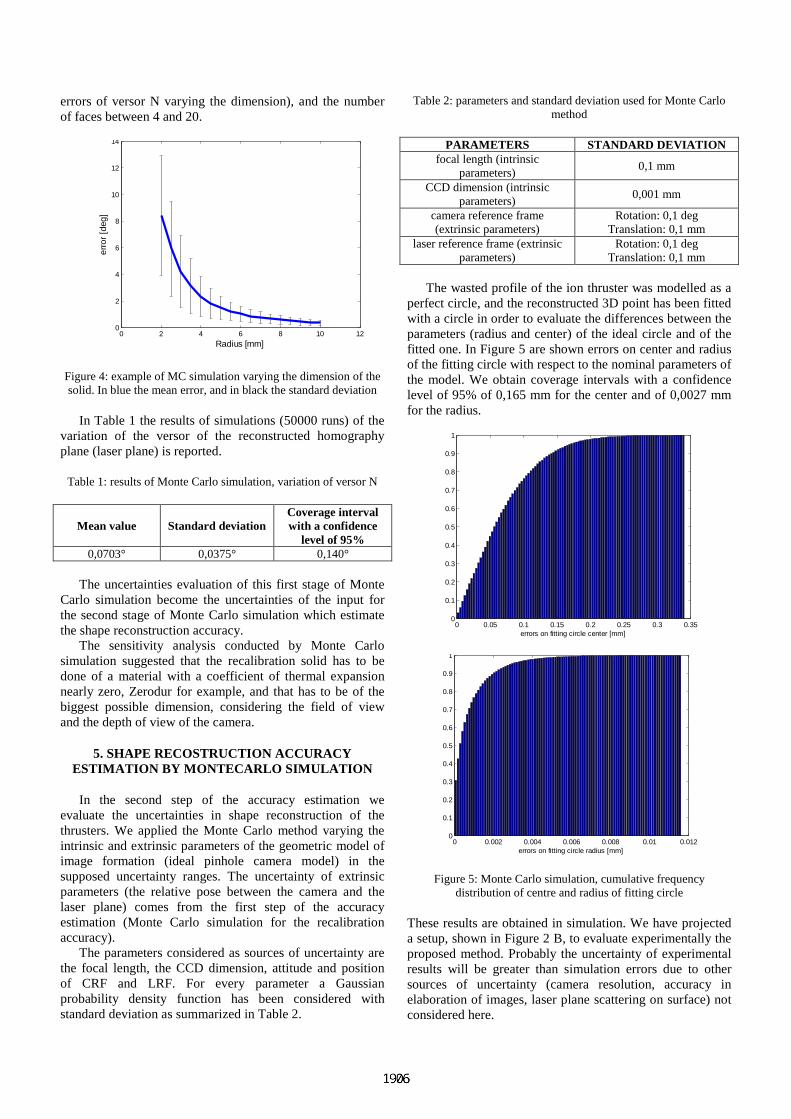
errors of versor N varying the dimension), and the number of faces between 4 and 20.
0 2 4 6 8 10 120
2
4
6
8
10
12
14
Radius [mm]
erro
r [d
eg]
Figure 4: example of MC simulation varying the dimension of the solid. In blue the mean error, and in black the standard deviation
In Table 1 the results of simulations (50000 runs) of the variation of the versor of the reconstructed homography plane (laser plane) is reported.
Table 1: results of Monte Carlo simulation, variation of versor N
Mean value Standard deviation Coverage interval with a confidence
level of 95% 0,0703° 0,0375° 0,140°
The uncertainties evaluation of this first stage of Monte
Carlo simulation become the uncertainties of the input for the second stage of Monte Carlo simulation which estimate the shape reconstruction accuracy.
The sensitivity analysis conducted by Monte Carlo simulation suggested that the recalibration solid has to be done of a material with a coefficient of thermal expansion nearly zero, Zerodur for example, and that has to be of the biggest possible dimension, considering the field of view and the depth of view of the camera.
5. SHAPE RECOSTRUCTION ACCURACY ESTIMATION BY MONTECARLO SIMULATION
In the second step of the accuracy estimation we evaluate the uncertainties in shape reconstruction of the thrusters. We applied the Monte Carlo method varying the intrinsic and extrinsic parameters of the geometric model of image formation (ideal pinhole camera model) in the supposed uncertainty ranges. The uncertainty of extrinsic parameters (the relative pose between the camera and the laser plane) comes from the first step of the accuracy estimation (Monte Carlo simulation for the recalibration accuracy).
The parameters considered as sources of uncertainty are the focal length, the CCD dimension, attitude and position of CRF and LRF. For every parameter a Gaussian probability density function has been considered with standard deviation as summarized in Table 2.
Table 2: parameters and standard deviation used for Monte Carlo method
PARAMETERS STANDARD DEVIATION focal length (intrinsic
parameters) 0,1 mm
CCD dimension (intrinsic parameters)
0,001 mm
camera reference frame (extrinsic parameters)
Rotation: 0,1 deg Translation: 0,1 mm
laser reference frame (extrinsic parameters)
Rotation: 0,1 deg Translation: 0,1 mm
The wasted profile of the ion thruster was modelled as a
perfect circle, and the reconstructed 3D point has been fitted with a circle in order to evaluate the differences between the parameters (radius and center) of the ideal circle and of the fitted one. In Figure 5 are shown errors on center and radius of the fitting circle with respect to the nominal parameters of the model. We obtain coverage intervals with a confidence level of 95% of 0,165 mm for the center and of 0,0027 mm for the radius.
0 0.05 0.1 0.15 0.2 0.25 0.3 0.350
0.1
0.2
0.3
0.4
0.5
0.6
0.7
0.8
0.9
1
errors on fitting circle center [mm]
0 0.002 0.004 0.006 0.008 0.01 0.0120
0.1
0.2
0.3
0.4
0.5
0.6
0.7
0.8
0.9
1
errors on fitting circle radius [mm]
Figure 5: Monte Carlo simulation, cumulative frequency distribution of centre and radius of fitting circle
These results are obtained in simulation. We have projected a setup, shown in Figure 2 B, to evaluate experimentally the proposed method. Probably the uncertainty of experimental results will be greater than simulation errors due to other sources of uncertainty (camera resolution, accuracy in elaboration of images, laser plane scattering on surface) not considered here.
6. EXPERIMENTAL EVALUATION OF MEASUREMENT ACCURACY OF THE VISION
SYSTEM
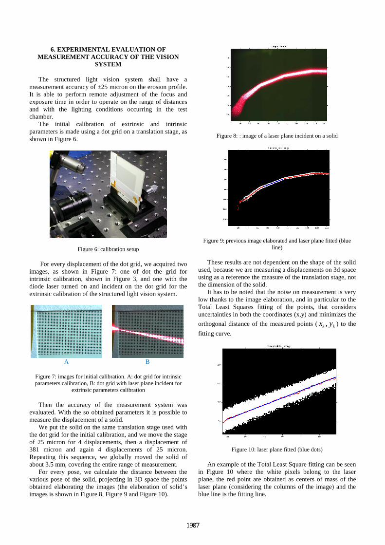
The structured light vision system shall have a measurement accuracy of ±25 micron on the erosion profile. It is able to perform remote adjustment of the focus and exposure time in order to operate on the range of distances and with the lighting conditions occurring in the test chamber.
The initial calibration of extrinsic and intrinsic parameters is made using a dot grid on a translation stage, as shown in Figure 6.
Figure 6: calibration setup
For every displacement of the dot grid, we acquired two images, as shown in Figure 7: one of dot the grid for intrinsic calibration, shown in Figure 3, and one with the diode laser turned on and incident on the dot grid for the extrinsic calibration of the structured light vision system.
A
B
Figure 7: images for initial calibration. A: dot grid for intrinsic parameters calibration, B: dot grid with laser plane incident for
extrinsic parameters calibration
Then the accuracy of the measurement system was evaluated. With the so obtained parameters it is possible to measure the displacement of a solid.
We put the solid on the same translation stage used with the dot grid for the initial calibration, and we move the stage of 25 micron for 4 displacements, then a displacement of 381 micron and again 4 displacements of 25 micron. Repeating this sequence, we globally moved the solid of about 3.5 mm, covering the entire range of measurement.
For every pose, we calculate the distance between the various pose of the solid, projecting in 3D space the points obtained elaborating the images (the elaboration of solid’s images is shown in Figure 8, Figure 9 and Figure 10).
Figure 8: : image of a laser plane incident on a solid
Figure 9: previous image elaborated and laser plane fitted (blue line)
These results are not dependent on the shape of the solid used, because we are measuring a displacements on 3d space using as a reference the measure of the translation stage, not the dimension of the solid.
It has to be noted that the noise on measurement is very low thanks to the image elaboration, and in particular to the Total Least Squares fitting of the points, that considers uncertainties in both the coordinates (x,y) and minimizes the
orthogonal distance of the measured points (,k kx y ) to the
fitting curve.
Figure 10: laser plane fitted (blue dots)
An example of the Total Least Square fitting can be seen in Figure 10 where the white pixels belong to the laser plane, the red point are obtained as centers of mass of the laser plane (considering the columns of the image) and the blue line is the fitting line.
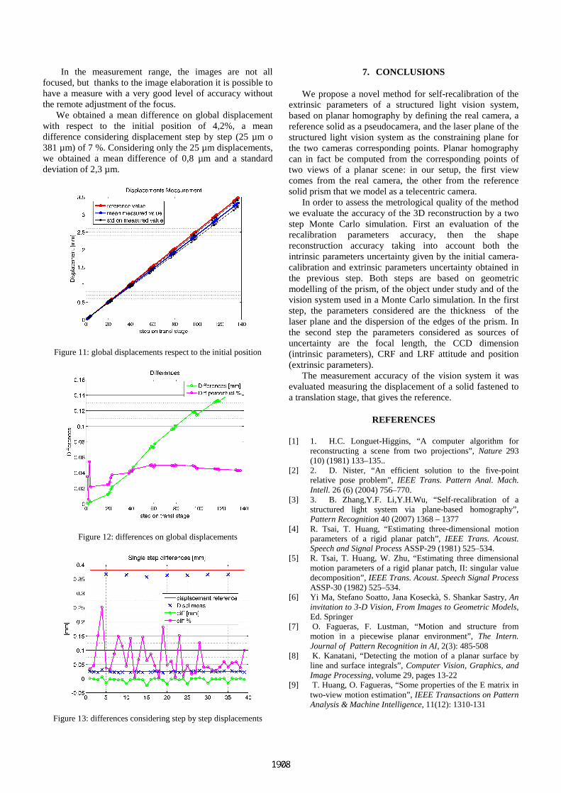
In the measurement range, the images are not all focused, but thanks to the image elaboration it is possible to have a measure with a very good level of accuracy without the remote adjustment of the focus.
We obtained a mean difference on global displacement with respect to the initial position of 4,2%, a mean difference considering displacement step by step (25 µm o 381 µm) of 7 %. Considering only the 25 µm displacements, we obtained a mean difference of 0,8 µm and a standard deviation of 2,3 µm.
Figure 11: global displacements respect to the initial position
Figure 12: differences on global displacements
Figure 13: differences considering step by step displacements
7. CONCLUSIONS
We propose a novel method for self-recalibration of the extrinsic parameters of a structured light vision system, based on planar homography by defining the real camera, a reference solid as a pseudocamera, and the laser plane of the structured light vision system as the constraining plane for the two cameras corresponding points. Planar homography can in fact be computed from the corresponding points of two views of a planar scene: in our setup, the first view comes from the real camera, the other from the reference solid prism that we model as a telecentric camera.
In order to assess the metrological quality of the method we evaluate the accuracy of the 3D reconstruction by a two step Monte Carlo simulation. First an evaluation of the recalibration parameters accuracy, then the shape reconstruction accuracy taking into account both the intrinsic parameters uncertainty given by the initial camera-calibration and extrinsic parameters uncertainty obtained in the previous step. Both steps are based on geometric modelling of the prism, of the object under study and of the vision system used in a Monte Carlo simulation. In the first step, the parameters considered are the thickness of the laser plane and the dispersion of the edges of the prism. In the second step the parameters considered as sources of uncertainty are the focal length, the CCD dimension (intrinsic parameters), CRF and LRF attitude and position (extrinsic parameters).
The measurement accuracy of the vision system it was evaluated measuring the displacement of a solid fastened to a translation stage, that gives the reference.
REFERENCES
[1] 1. H.C. Longuet-Higgins, “A computer algorithm for reconstructing a scene from two projections”, Nature 293 (10) (1981) 133–135..
[2] 2. D. Nister, “An efficient solution to the five-point relative pose problem”, IEEE Trans. Pattern Anal. Mach. Intell. 26 (6) (2004) 756–770.
[3] 3. B. Zhang,Y.F. Li,Y.H.Wu, “Self-recalibration of a structured light system via plane-based homography”, Pattern Recognition 40 (2007) 1368 – 1377
[4] R. Tsai, T. Huang, “Estimating three-dimensional motion parameters of a rigid planar patch”, IEEE Trans. Acoust. Speech and Signal Process ASSP-29 (1981) 525–534.
[5] R. Tsai, T. Huang, W. Zhu, “Estimating three dimensional motion parameters of a rigid planar patch, II: singular value decomposition”, IEEE Trans. Acoust. Speech Signal Process ASSP-30 (1982) 525–534.
[6] Yi Ma, Stefano Soatto, Jana Koseckà, S. Shankar Sastry, An invitation to 3-D Vision, From Images to Geometric Models, Ed. Springer
[7] O. Fagueras, F. Lustman, “Motion and structure from motion in a piecewise planar environment”, The Intern. Journal of Pattern Recognition in AI, 2(3): 485-508
[8] K. Kanatani, “Detecting the motion of a planar surface by line and surface integrals”, Computer Vision, Graphics, and Image Processing, volume 29, pages 13-22
[9] T. Huang, O. Fagueras, “Some properties of the E matrix in two-view motion estimation”, IEEE Transactions on Pattern Analysis & Machine Intelligence, 11(12): 1310-131