Extramedullary Tibial Preparation - Smith & Nephe tibial preparation Contents Introduction .....2 EM...
20
Surgical Technique Extramedullary Tibial Preparation Primary Total Knee Arthroplasty
Transcript of Extramedullary Tibial Preparation - Smith & Nephe tibial preparation Contents Introduction .....2 EM...

Surgical Technique
Extramedullary Tibial PreparationPrimary Total Knee Arthroplasty


1
LEGION™ Total Knee System
Extramedullary tibial preparation
Contents
Introduction ...............................................................2
EM tibial highlights ....................................................3
Preoperative planning ...............................................4
Instrument assembly ................................................5
EM tibial preparation .................................................6
Tibial resection ..........................................................8
Tibial sizing ................................................................10
Component trialing ....................................................12
Implantation ..............................................................14
Appendix A ...............................................................16
Appendix B ................................................................17
Nota Bene
The technique description herein is made available to the healthcare professional to illustrate the authors’ suggested treatment for the uncomplicated procedure. In the final analysis, the preferred treatment is that which addresses the needs of the patient.
Additional LEGION Total Knee System surgical technique brochures are available for the other LEGION Components.

2
Introduction
The LEGION™ Total Knee System has been designed to offer the orthopaedic surgeon solutions to address intraoperative situations. Implant function is directly related to accurate surgical technique. LEGION instrumentation has been developed to be an easy-to-use system that will assist the surgeon in obtaining accurate and reproducible knee alignment.
The instrumentation can be used in minimally invasive or standard exposures. While it has been the designers’ objective to develop accurate, easy-to-use instrumentation, each surgeon must evaluate the appropriateness of the following technique based on his or her medical training, experience and patient evaluation.

3
EM tibial highlights
Place the extramedullary tibial guide with the non-spiked (shown) or spiked rod and place on tibia. Align guide over medial third of the tibial tubercle and parallel to the tibia.
Attach the tibial stylus to the tibial cutting block and lower the cutting block until the stylus touches the low point on the least affected side of the tibia. Once the resection level is determined, insert pins to secure and remove alignment assembly.
Resect the proximal tibia.
Size the tibia.
Final preparation
After trial ROM and alignment checks, select the appropriate trial fin punch and punch through the trial.
Seat the tibial implant with the tibial impactor.
Attach the articular inserter/extractor to the tibial tray (for standard inserts). Lift inserter superiorly until the anterior lip of the insert is fully seated.
4
Preoperative planning
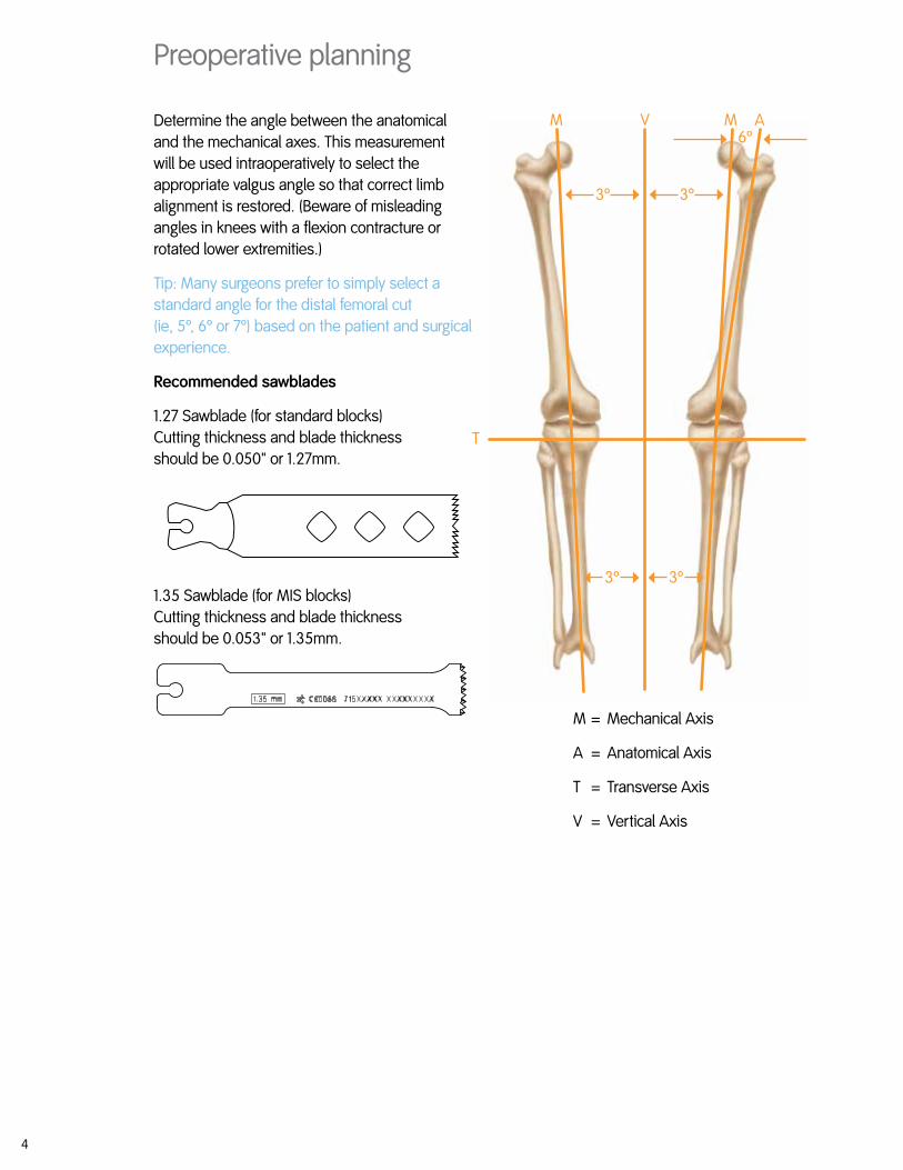
Determine the angle between the anatomical and the mechanical axes. This measurement will be used intraoperatively to select the appropriate valgus angle so that correct limb alignment is restored. (Beware of misleading angles in knees with a flexion contracture or rotated lower extremities.)
Tip: Many surgeons prefer to simply select a standard angle for the distal femoral cut (ie, 5º, 6º or 7º) based on the patient and surgical experience.
Recommended sawblades
1.27 Sawblade (for standard blocks) Cutting thickness and blade thickness should be 0.050" or 1.27mm.
1.35 Sawblade (for MIS blocks) Cutting thickness and blade thickness should be 0.053" or 1.35mm.
M = Mechanical Axis
A = Anatomical Axis
T = Transverse Axis
V = Vertical Axis
M
T
M AV6º
3º
3º 3º
3º

5
Instrument assemblyExtramedullary tibial alignment guide
Insert the ankle clamp into the distal end of the alignment tube and thread the locking pin into the ankle clamp (Figure 1).
After the ankle clamp is moved into the proper position, lock into place with the gold knob.
Choose the correct left or right tibial cutting block. Select the spiked or non-spiked fixation rod.
Non-spiked fixation rod
Place the appropriate left or right tibial cutting block on top of the disc on the non-spiked fixation rod (Figure 2). Tighten the central knob to lock the block into position.
Introduce the rod into the extramedullary assembly and adjust and lock the cam in the assembly.
Spiked fixation rod
Place the spiked fixation rod through the hole in the tibial cutting guide; adjust the block and tighten the central knob to lock the block into position.
Introduce the spiked fixation rod into the proximal end of the alignment assembly and adjust and lock the cam on the assembly (Figure 3).
Ankle Clamp7144-0444
Non-spiked Fixation Rod7144-0446
Spiked Fixation Rod7144-0198
Alignment Tube7144-0448
Tibial Cutting BlockLeft 7144-1136Right 7144-1137
Gold Knob
Central Knob
Locking Cam
Figure 1
Figure 2
Figure 3

6
EM tibial preparationWhen using the extramedullary tibial alignment, the surgeon may use a non-spiked or spiked fixation rod.
Non-spiked fixation
1 Place the arms of the extramedullary alignment clamp around the ankle, and adjust the distal M/L slide directly over the middle of the tibiotalar joint, which is also approximated by the second ray of the foot proximal to the malleoli (Figure 4).
The cutting block on the proximal end of the assembly should be proximal to the tibial tubercle (Figure 5).
2 Assess rotation of the alignment guide and slope of the cutting plane. The goal is to align the extramedullary alignment assembly rotationally so that it aligns over the medial third of the tibial tubercle and over the second toe (Figure 6).
3 Rotational alignment is critical due to the 3° posterior sloped cut. The slope can be adjusted according to the patient’s anatomy (Figure 7).
Note: 3-5° of slope is built into the articular insert (depending on which insert is chosen) and 3° of slope is built into the tibial cutting block. A neutral or slightly sloped alignment should usually be chosen.
Tip: Neutral or minimally sloped alignment may be achieved by palpating the fibula followed by aligning the alignment guide parallel to the fibula. Tibial bowing and soft tissue bulk may make external tibial referencing unreliable.
Figure 4 Figure 5
Figure 7Figure 6
Ankle Clamp7144-0444
Non-spiked Fixation Rod7144-0446
Alignment Tube7144-0448
Tibial Cutting BlockLeft 7144-1136Right 7144-1137
7
Figure 9
Figure 8
Figure 12
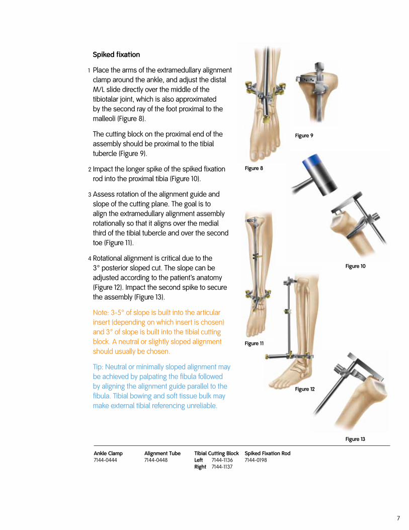
Spiked fixation
1 Place the arms of the extramedullary alignment clamp around the ankle, and adjust the distal M/L slide directly over the middle of the tibiotalar joint, which is also approximated by the second ray of the foot proximal to the malleoli (Figure 8).
The cutting block on the proximal end of the assembly should be proximal to the tibial tubercle (Figure 9).
2 Impact the longer spike of the spiked fixation rod into the proximal tibia (Figure 10).
3 Assess rotation of the alignment guide and slope of the cutting plane. The goal is to align the extramedullary alignment assembly rotationally so that it aligns over the medial third of the tibial tubercle and over the second toe (Figure 11).
4 Rotational alignment is critical due to the 3° posterior sloped cut. The slope can be adjusted according to the patient’s anatomy (Figure 12). Impact the second spike to secure the assembly (Figure 13).
Note: 3-5° of slope is built into the articular insert (depending on which insert is chosen) and 3° of slope is built into the tibial cutting block. A neutral or slightly sloped alignment should usually be chosen.
Tip: Neutral or minimally sloped alignment may be achieved by palpating the fibula followed by aligning the alignment guide parallel to the fibula. Tibial bowing and soft tissue bulk may make external tibial referencing unreliable.
Figure 13
Figure 10
Ankle Clamp7144-0444
Spiked Fixation Rod7144-0198
Alignment Tube7144-0448
Tibial Cutting BlockLeft 7144-1136Right 7144-1137
Figure 11

8
Tibial resection
1 Attach the tibial stylus to the tibial cutting block by inserting the stylus foot into the cutting slot.
2 Lower the cutting block until the stylus touches the low point on the least affected side of the tibia (Figure 14). The stylus can be adjusted for a 1-13mm tibial resection by twisting the knob on top of the stylus. If the affected side of the tibia is to be used as a reference, the stylus may be adjusted for a 1-9mm resection level.
3 Pin the tibial cutting block to the tibia by inserting pins first through the central holes; then the oblique hole.
Tip: Pinning through the central holes marked 0mm with smooth pins will allow the block to be moved +2mm should additional resection be required (Figure 15).
Tip: A 9mm resection is recommended since 9mm of metal and plastic is the thinnest available component.
Tip: To do an extramedullary alignment check, place the extramedullary alignment rod through the tibial cutting block.
Figure 14
Figure 15
Tibial Stylus7144-1143
Alignment Rod7144-1148
Tibial Cutting BlockLeft 7144-1136Right 7144-1137

9
4 To remove the assembly: a For the assembly with spiked rod, release the
cam at the top of the alignment tube and use the slap hammer to remove the spiked fixation rod (Figure 16) after loosening the thumbscrew.
b The assembly with the non-spiked rod may be left in place or removed by loosening the thumbscrew and lowering the non-spiked rod to disengage from the tibial cutting block.
5 Cut the tibia by first directing the blade in the posterior direction and then laterally (Figure 17).
6 Check alignment and balance with spacer block and rod (Figures 18-19). Balance ligaments in standard fashion.
Tip: If you are using a spacer block from the GENESIS™ II set (Figure 19), use the extension end to check both flexion and extension spaces.
Universal Extractor (Slap Hammer)7144-0366
Tibial Cutting BlockLeft 7144-1136Right 7144-1137
Spacer Block (original two-sided)7144-0828
Spacer Block (new one-sided)7144-1265
Figure 19Figure 18
Knob (unlocked)
Spacer Block
Figure 16
Figure 17

10
Tibial sizingOption A – stemless tibial trials
1 Attach a quick-connect handle to a stemless trial one size below the femoral component size and place on the cut tibia to assess coverage (Figure 20). As needed, additional sizes should be templated using the stemless trials.
2 Once the appropriate size is determined, pin the medial size of the selected stemless trial with a short headed pin.
3 Place a trial insert into the stemless tibial trial tray and perform a trial range of motion to allow the baseplate to center on the femoral trial. (As a secondary check, the surgeon may pass the alignment rod through the quick-connect handle to assess alignment) (Figure 21). Pin the lateral side of the trial.
Tip: After putting the knee through a trial ROM, the surgeon should note the proper rotation of the trial tibial component on the proximal tibia and mark the tibia for future reference.
Tip: The center-line marks on the femoral and tibial trial components should line up.
4 Using the tibial fin/stem punch, rotational alignment may be set now or at the time of trial placement.
Tip: If the tibial bone is sclerotic, first drill for the stem using the 11mm tibial drill. Begin the fin slot with a burr or thin sawblade before using the fin punch to prevent tibial fracture.
Figure 20
Figure 21
Drop Rod
Quick-connect Handle
Quick-connect Handle7144-00447144-0045
Fin/Stem Punchsz 1-2 7144-9991sz 3-4 7144-9993sz 5-6 7144-9995sz 7-8 7144-9997
Stemless Trials Leftsz 1 7143-0161sz 2 7143-0163sz 3 7143-0165sz 4 7143-0167sz 5 7143-0169sz 6 7143-0171sz 7 7143-0173sz 8 7143-0175
Right sz 1 7143-0177sz 2 7143-0179sz 3 7143-0181sz 4 7143-0183sz 5 7143-0185sz 6 7143-0187sz 7 7143-0189sz 8 7143-0191
11mm Tibial Drill7144-0040
11
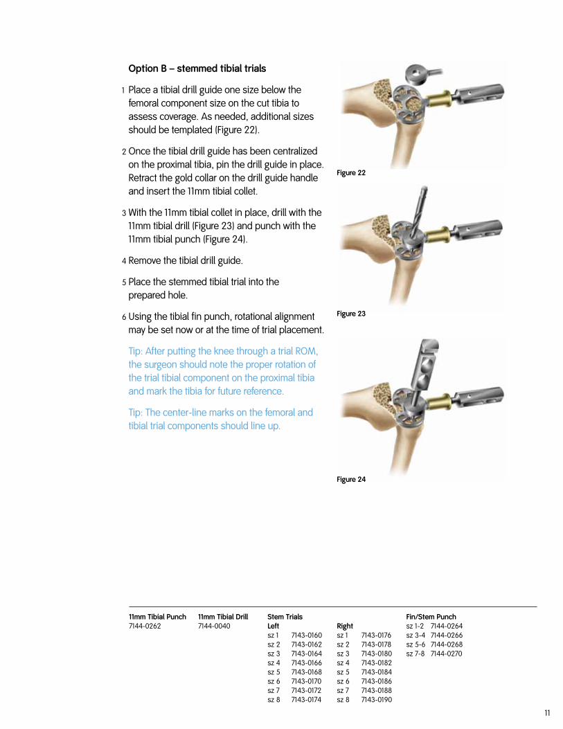
Option B – stemmed tibial trials
1 Place a tibial drill guide one size below the femoral component size on the cut tibia to assess coverage. As needed, additional sizes should be templated (Figure 22).
2 Once the tibial drill guide has been centralized on the proximal tibia, pin the drill guide in place. Retract the gold collar on the drill guide handle and insert the 11mm tibial collet.
3 With the 11mm tibial collet in place, drill with the 11mm tibial drill (Figure 23) and punch with the 11mm tibial punch (Figure 24).
4 Remove the tibial drill guide.
5 Place the stemmed tibial trial into theprepared hole.
6 Using the tibial fin punch, rotational alignment may be set now or at the time of trial placement.
Tip: After putting the knee through a trial ROM, the surgeon should note the proper rotation of the trial tibial component on the proximal tibia and mark the tibia for future reference.
Tip: The center-line marks on the femoral and tibial trial components should line up.
Figure 22
Figure 23
Figure 24
11mm Tibial Drill7144-0040
Fin/Stem Punchsz 1-2 7144-0264sz 3-4 7144-0266sz 5-6 7144-0268sz 7-8 7144-0270
Stem Trials Leftsz 1 7143-0160sz 2 7143-0162sz 3 7143-0164sz 4 7143-0166sz 5 7143-0168sz 6 7143-0170sz 7 7143-0172sz 8 7143-0174
Right sz 1 7143-0176sz 2 7143-0178sz 3 7143-0180sz 4 7143-0182sz 5 7143-0184sz 6 7143-0186sz 7 7143-0188sz 8 7143-0190
11mm Tibial Punch7144-0262

12
Figure 25
Figure 26
Component trialing
1 Use the appropriate insert trial (begin with a 9mm trial) to determine stability and alignment.
2 Perform a trial range of motion. The alignment marks on the front of the femoral and tibial trials should line up (Figure 25). The quick-connect handle may be attached to the tibial trial and used to set the appropriate rotational alignment.
Option: Extend the knee fully with the handle attached to the tibial trial. Pass the extramedullary rod through the handle to assess full leg alignment (Figure 26).
Tip: The technique of tibial trial, then femoral trial and then trial insert works for all LEGION™ primary inserts except the dished inserts. For the deep dished, insert the trial bearing BEFORE the femoral trial.
Insert Trial Spacers13mmsz 1-2 7143-0324 sz 3-4 7143-0226sz 5-6 7143-0228sz 7-8 7143-023015mmsz 1-2 7143-0332 sz 3-4 7143-0234sz 5-6 7143-0236sz 7-8 7143-023818mmsz 1-2 7143-0340 sz 3-4 7143-0242sz 5-6 7143-0244sz 7-8 7143-024621mmsz 1-2 7143-0348 sz 3-4 7143-0250sz 5-6 7143-0252sz 7-8 7143-025425mmsz 1-2 7143-0356 sz 3-4 7143-0258sz 5-6 7143-0260sz 7-8 7143-0262
CR Insert Trials9mm sz 1-2 7143-0880sz 3-4 7143-0490sz 5-6 7143-0500sz 7-8 7143-051011mm sz 1-2 7143-0882 sz 3-4 7143-0492sz 5-6 7143-0502sz 7-8 7143-0512
PS Insert Trials9mm sz 1-2 7143-0901 sz 3-4 7143-0815 sz 5-6 7143-0829 sz 7-8 7143-0844 11mm sz 1-2 7143-0903sz 3-4 7143-0817 sz 5-6 7143-0831 sz 7-8 7143-0846
Deep Dished Insert Trials9mmsz 1-2 7143-0454 sz 3-4 7143-0766sz 5-6 7143-0778sz 7-8 7143-078911mmsz 1-2 7143-0456 sz 3-4 7143-0768sz 5-6 7143-0780sz 7-8 7143-0791
Constrained Insert Trials 9mmsz 1-2 7144-0471sz 3-4 7144-0473sz 5-6 7144-0475sz 7-8 7144-0477 11mmsz 1-2 7143-0962sz 3-4 7143-0524sz 5-6 7143-0538sz 7-8 7143-0552
PS High Flex Insert Trials 9mm sz 1-2 7143-0401 sz 3-4 7143-0408 sz 5-6 7143-0415sz 7-8 7143-042211mmsz 1-2 7143-0402sz 3-4 7143-0409sz 5-6 7143-0416 sz 7-8 7143-0423
CR Deep Flex Insert Trials 9mmsz 1-2 7143-0442 sz 3-4 7143-0444sz 5-6 7143-0446sz 7-8 7143-0448 11mmsz 1-2 7143-0443 sz 3-4 7143-0445 sz 5-6 7143-0447 sz 7-8 7143-0449
13
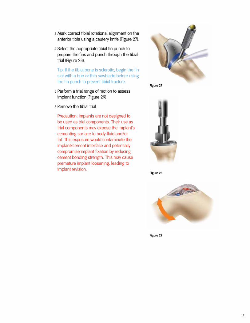
3 Mark correct tibial rotational alignment on the anterior tibia using a cautery knife (Figure 27).
4 Select the appropriate tibial fin punch to prepare the fins and punch through the tibial trial (Figure 28).
Tip: If the tibial bone is sclerotic, begin the fin slot with a burr or thin sawblade before using the fin punch to prevent tibial fracture.
5 Perform a trial range of motion to assess implant function (Figure 29).
6 Remove the tibial trial.
Precaution: Implants are not designed to be used as trial components. Their use as trial components may expose the implant’s cementing surface to body fluid and/or fat. This exposure would contaminate the implant/cement interface and potentially compromise implant fixation by reducing cement bonding strength. This may cause premature implant loosening, leading to implant revision.
Figure 27
Figure 28
Figure 29

14
ImplantationTibial implantation
1 Apply cement on the proximal tibia and/or the implant and seat the tibial implant with the tibial impactor (Figure 30). Remove excess cement.
Cruciate-retaining, dished and posterior stabilized insert placement
1 Determine the correct articular insert thickness.
2 Clear any debris from the locking mechanism and slide the insert into the tibial baseplate engaging the locking mechanism. For the PS insert, begin insertion in flexion and extend the leg to engage the locking mechanism.
3 Attach the articular inserter/extractor to the tibial tray. Lift the inserter superiorly until the anterior lip of the articular insert is fully seated (Figure 31).
Tibial Base Impactor7144-0192
Articular Inserter/Extractor7144-0194
Figure 31
Figure 30

15
PS high flex and CR deep flex insert placement
1 Attach the appropriately sized impactor head (either 1-2 or 3-8) to the impactor handle.
2 Position the knee in approximately 90° flexion.
3 Align the articular insert with the locking mechanism of the tibial baseplate.
4 Push the insert posteriorly until the top of the anterior rail of the baseplate is visible.
5 Place the bumper on the anterior chamfer of the insert. The mating surfaces should be very conforming (Figures 32 and 33).
6 Impact the handle until the insert is fully seated.
MIS Note: To use the PS high flexion insert in minimally invasive surgery, please see the technique described in Appendix A.
High-flex Impactor Headsz 1-2 7144-1553sz 3-8 7144-1554
High-flex Impactor Handle7144-1552
Bone Cement
Figure 32
Figure 33
16
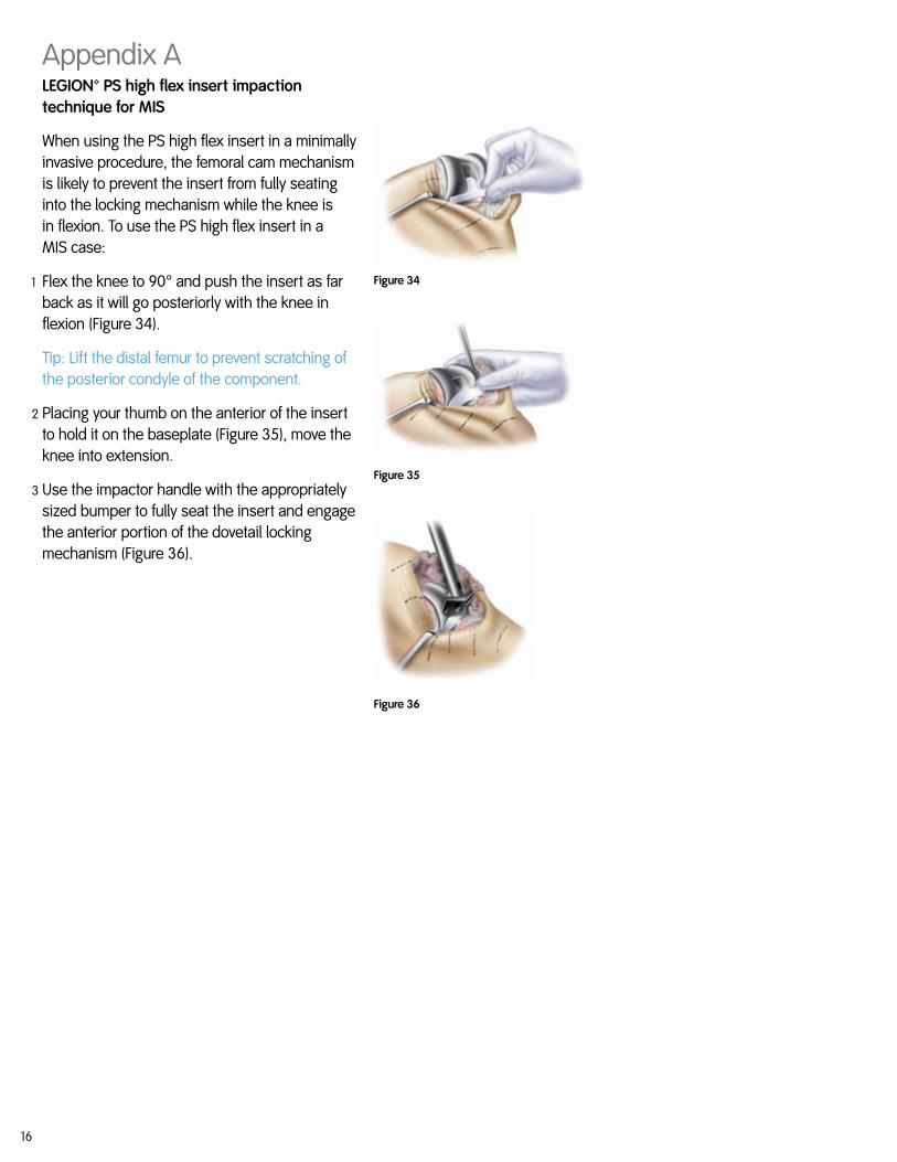
Appendix ALEGION™ PS high flex insert impaction technique for MIS
When using the PS high flex insert in a minimally invasive procedure, the femoral cam mechanism is likely to prevent the insert from fully seating into the locking mechanism while the knee is in flexion. To use the PS high flex insert in a MIS case:
1 Flex the knee to 90° and push the insert as far back as it will go posteriorly with the knee in flexion (Figure 34).
Tip: Lift the distal femur to prevent scratching of the posterior condyle of the component.
2 Placing your thumb on the anterior of the insert to hold it on the baseplate (Figure 35), move the knee into extension.
3 Use the impactor handle with the appropriately sized bumper to fully seat the insert and engage the anterior portion of the dovetail locking mechanism (Figure 36).
Figure 34
Figure 35
Figure 36
17
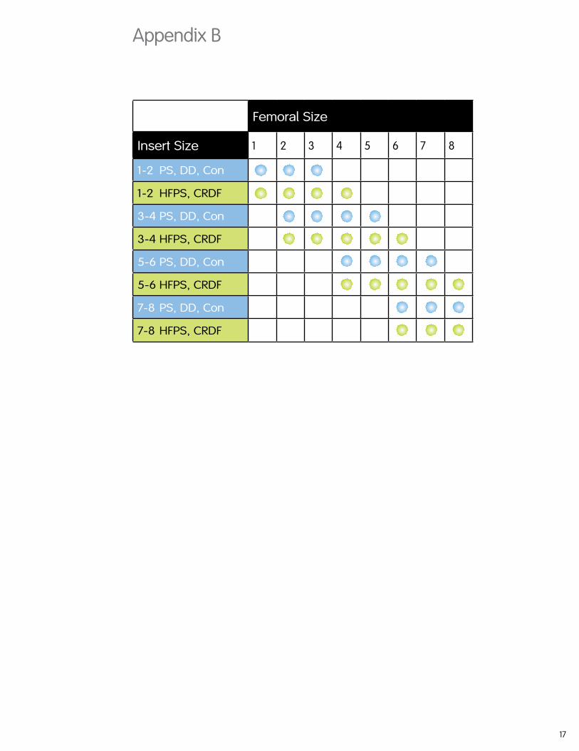
Appendix B
Femoral Size
Insert Size 1 2 3 4 5 6 7 8
1-2 PS, DD, Con
1-2 HFPS, CRDF
3-4 PS, DD, Con
3-4 HFPS, CRDF
5-6 PS, DD, Con
5-6 HFPS, CRDF
7-8 PS, DD, Con
7-8 HFPS, CRDF

OrthopaedicsSmith & Nephew, Inc.1450 Brooks RoadMemphis, TN 38116USA
Telephone: 1-901-396-2121Information: 1-800-821-5700Orders and Inquiries: 1-800-238-7538
www.smith-nephew.comwww.legionpower.com
™Trademark of Smith & Nephew. Registered US Patent and Trademark Office.
©2010 Smith & Nephew, IncAll rights reserved.7128-1673 REVB 08/10