External Knee Joint Design Based on Normal Motion
14
Veterans Administration P. S. WALKER, Ph. D.' H. KUROSAWA, M.D.~ J. S. ROVICK, M.A.' R. A. ZIMMERMAN, B.S.' Veterans Administration Medical Center West Roxbury, Massachusetts Brigham and Women's Hospital Boston, Massachusetts Department of Orthopedic Surgery University of Tokyo Japan aClinical Bioengineering, VA Medical Cen- ter, West Roxbury, Massachusetts, and Orthopedic Biomechanics, Brigham and Women's Hospital, Boston, Massachu- setts, teaching affiliates of Harvard Med- ical School b~epartment of Orthopedic Surgery, Uni- versity of Tokyo, Japan. CThis work was supported by the Veterans Administration Rehabilitation Research and Development Service and by Brigham Orthopedic Associates. The authors acknowledge the contribu- tion of several students from the Massa- chusetts lnstitute of Technology and the Wentworth Institute of Technology: John Holbrook, Tom Clarke, Phil Carbone, Karen Soltesz, and Arunas Chesonis. Reprint requests should be directed to: Peter S. Walker, Ph. D., Clinical Bioengi- neering Research Service, VA Medical Center, 1400 V.F.W. Parkway, West Rox- bury,MA02132 External Knee Joint Design Based on Normal Motionc Abslrael-There are several advantages to accurate reproduction of knee motion in an external joint assembly such as a knee brace: reduction of pistoning forces, better ligament protection, kinematic compatability. The geometry and kinematics of the normal human knee were studied and the results applied to external joint design. Geometrically, the posterior portions of the femoral condyles were found to be spherical in shape. These spherical surfaces are projected in sagittal plane radiographs as circles with center points coincident with those of the spheres. A line connecting these centers defines an axis system and enables three-dimensional orientation of the femur on the tibia to be determined using sagittal-plane radiographs. Knee kinematics was determined as a function of flexion angle for 14 fresh cadavers and 8 volunteers. Results were in the form of eulerian rotations and displacements. The data were normalized to the size of the average knee and the results from the 22 trials were averaged. The most obvious motion was internal rotation of the tibia with flexion; however, varus rotation and posterior translation of the origin were also evident. An external joint system was then designed to mimic "average" knee motion during flexion. The joints have been incorporated into a knee brace, and clinical evaluation has begun. Other applications include cast bracing and hinge distraction. The external joints built into knee braces are designed to be reasonably compatible with joint motion, but the main purposes of the braces themselves are to provide stability or to restrict the motion. Many of the external joints used today are of the fixed- axis type which defines a single axis of rotation. Others use poly- centric linkages, to produce a gradual posterior motion of the femur relative to the tibia during flexion to reproduce the ''roll- back" which occurs anatomically. These polycentric devices are applied so as to produce equal motions on each side of the joint. Even if knee motion could be represented by a fixed axis or polycentric motion, accurate placement would be essential. For example, different placements of the axis in the sagittal plane can result in condylar impingement, condylar separation, or excessive roll-back, during flexion (1). The extent to which the linkages are incompatible with the correct motion is taken up by deformation of soft tissue, or by cuff-to-skin slippage. Lew et al. (2) measured
Transcript of External Knee Joint Design Based on Normal Motion
Veterans Administration
P. S. WALKER, Ph. D.' H. KUROSAWA, M . D . ~ J. S. ROVICK, M.A.' R. A. ZIMMERMAN, B.S.'
Veterans Administration Medical Center West Roxbury, Massachusetts
Brigham and Women's Hospital Boston, Massachusetts
Department of Orthopedic Surgery University of Tokyo Japan
aClinical Bioengineering, VA Medical Cen- ter, West Roxbury, Massachusetts, and Orthopedic Biomechanics, Brigham and Women's Hospital, Boston, Massachu- setts, teaching affiliates of Harvard Med- ical School
b~epartment of Orthopedic Surgery, Uni- versity of Tokyo, Japan.
CThis work was supported by the Veterans Administration Rehabilitation Research and Development Service and by Brigham Orthopedic Associates. The authors acknowledge the contribu-
tion of several students from the Massa- chusetts lnstitute of Technology and the Wentworth Institute of Technology: John Holbrook, Tom Clarke, Phil Carbone, Karen Soltesz, and Arunas Chesonis.
Reprint requests should be directed to: Peter S. Walker, Ph. D., Clinical Bioengi- neering Research Service, VA Medical Center, 1400 V.F.W. Parkway, West Rox- bury,MA02132
External Knee Joint Design Based on Normal Motionc
Abslrael-There are several advantages to accurate reproduction of knee motion in an external joint assembly such as a knee brace: reduction of pistoning forces, better ligament protection, kinematic compatability. The geometry and kinematics of the normal human knee were studied and the results applied to external joint design.
Geometrically, the posterior portions of the femoral condyles were found to be spherical in shape. These spherical surfaces are projected in sagittal plane radiographs as circles with center points coincident with those of the spheres. A line connecting these centers defines an axis system and enables three-dimensional orientation of the femur on the tibia to be determined using sagittal-plane radiographs.
Knee kinematics was determined as a function of flexion angle for 14 fresh cadavers and 8 volunteers. Results were in the form of eulerian rotations and displacements. The data were normalized to the size of the average knee and the results from the 22 trials were averaged. The most obvious motion was internal rotation of the tibia with flexion; however, varus rotation and posterior translation of the origin were also evident. An external joint system was then designed to mimic "average" knee motion during flexion. The joints have been incorporated into a knee brace, and clinical evaluation has begun. Other applications include cast bracing and hinge distraction.
The external joints built into knee braces are designed to be reasonably compatible with joint motion, but the main purposes of the braces themselves are to provide stability or to restrict the motion. Many of the external joints used today are of the fixed- axis type which defines a single axis of rotation. Others use poly- centric linkages, to produce a gradual posterior motion of the femur relative to the tibia during flexion to reproduce the ''roll- back" which occurs anatomically. These polycentric devices are applied so as to produce equal motions on each side of the joint.
Even i f knee motion could be represented by a fixed axis or polycentric motion, accurate placement would be essential. For example, different placements of the axis in the sagittal plane can result in condylar impingement, condylar separation, or excessive roll-back, during flexion (1). The extent to which the linkages are incompatible with the correct motion is taken up by deformation of soft tissue, or by cuff-to-skin slippage. Lew et al. (2) measured

WALKER gt 813,: f xternal Knee Jornl Design
plstswlng forces across leg braces for different activities, and suggested that both joint design and placement affected the magnitude of the forces.
!a an Increasing number of applications today, accurate motion is very important. In the protection of Ilgament injuries, or protection after surgical reconstruction, immobilization has many disadvan- tages. Mobility is far preferable, but the correct ligament length patterns must be maintained to prevent further injury or damage that may nullify a repair. Accuracy to only a few millimeters is needed, because of the load-deflection characteristics of ligaments (3). Even greater accuracy may be needed if the external linkages are applied to a hinge-distrac- tor that is fitted rigidly to the bones using trans- cutaneous pins (4).
However, available data on knee motion may not be easily adapted to the problems of designing and positioning the external joints. Geometrical data is restricted to linear measurements in different planes (5,6) or to a description of the sagittal profiles of the femoral condyles (6,7,8). Describing motion by in- stant centers of rotation found by following points on the profiles or on the long axis of the femur, whether on a single plane or of both femoral con- dyles separately, has been found to be extremely variable and subject to serious inaccuracies (9). Goniometric (10) and light-emitting-diode methods (11) have been successfully applied to gait studies, but so far, internal joint motion related to identifiable bony landmarks has not been extrapolated. Accurate three-dimensional motion, described by three Euler- ian angles and three translations, or by the screw axis, could be determined by biplanar radiography using small embedded metallic beads in the bones (12), or by a six-degrees-of-freedom linkage connect- ing the femur and the tibia (13). A study with some application to our problem also considered a six- degrees-of-freedom description (14) and applied the method to define an optimal single axis of rotation (1 5).
Our objectives were to determine three-dimensional knee motion with respect to readily indentifiable bony landmarks, and to use the data to design the external joints themselves. First, geometrical prop- erties of the knee were determined and used to define the axis system. Second, the motion of normal knees was measured with respect to the defined axes. Third, a computer graphics program was written to design external joints with certain parameters optimized.
MATERIALS AND METHODS
Scaling - In an attempt to standardize all of the geometrical and motion data to an average-size knee, measurements for each bone or joint were linearly scaled up or down. For the femoral condyles, a convenient dimension was the maximum medial- lateral width, taken to be 80 millimeters for the average knee. In the case of the motion studies when sagittal plane radiographs were used, the aver- age anterior-posterior depth of the upper tibia was taken to be 50 millimeters. These dime..sions were from Mensch and Amstutz (5) and from our own un- published data.
Geometry - An investigation was made to deter- mine whether spherical surfaces would be an accur- ate model for the posterior parts of the lateral and medial femoral condyles. If so, the centers of the spheres determined from sagittal radiographs could be used as two reference points.
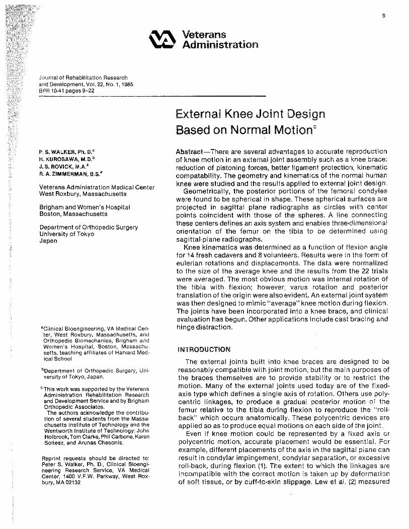
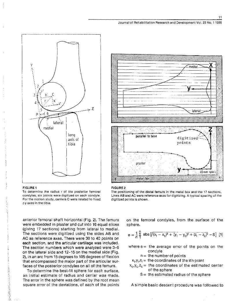
Fourteen fresh normal knee specimens with no pathological changes were obtained, cut about 20 centimeters above and below the joint line. The muscles were removed, but the patella, patella ten- don, the cruciate ligaments, the collateral ligaments and the capsule were retained. The tibia was ce- mented into a metal base, such that a line across the posteriors of the medial and lateral plateaus was approximately transverse, and with the long axis vertical in the frontal and sagittal planes. Radio- graphs were taken in the sagittal plane, placed in a rear-lit digitizer, and six points on the lateral and medial femoral condyles were digitized (Fig. 1). Two sets of three points (1,3,5; 2,4,6) were used to calcu- late the radius and the center (16), and the results were averaged.
After completing the motion study on these knees (described later), the femur was separated and the radii of the sagittal and frontal planes of the femoral condyles were measured using radius gauges. The gauges enclosed a 90-degree arc, and were made at 1 millimeter radial increments. Frontal outlines were measured at locations corresponding to flexion angles from 0 to 120 degrees in 30-degree increments. The medial-lateral spacings of the medial and lateral condyles were also measured. The thickness of the articular cartilage was measured on the radiographs and directly on four specimens, to compare the radiographic radii measured on the bony outlines with the radius-gauge results measured on the cartilage.
A further 22 distal femurs were obtained and aligned in a metal box, with the posterior and distal femoral condyles lying on two perpendicular planes and the
i 1
Journal of Rehabilitation Research and Development Voi. 22 No. 1 1985
FIGURE 1 FIGURE 2 To determine the radius r of the posterior femoral The positioning of the distal femurs in the metal box and the 17 sections. condyles, six points were digitized on each condyle. Lines AB and AC were reference axes for digitizing. A typical spacing of the For the motion study, centers C were related to fixed digitized points is shown. z-y axes in the tibia.
anterior femoral shaft horizontal (Fig. 2). The femurs were embedded in plaster and cut into 16 equal slices (giving 17 sections) starting from lateral to medial. The sections were digitized using the sides AB and AC as reference axes. There were 30 to 40 points on each section, and the articular cartilage was included. The section numbers which were analyzed were 3-6 on the lateral side and 12-15 on the medial side (Fig. 2), in an arc from 15 degrees to 105 degrees of flexion that encompassed the major part of the articular sur- faces of the posterior condyles on all of the femurs.
To determine the best-fit sphere for each surface, an initial estimate of radius and center was made. The error in the sphere was defined by the root mean square error of the deviations, of each of the points
on the femoral condyles, from the surface of the sphere.
where e = the average error of the points on the condyle
n = the number of points Xiqyiqzi = the coordinates of the ith point
xc,y,,zc = the coordinates of the estimated center of the sphere
S = the estimated radius of the sphere
A simple basic descent procedure was followed to

12
WALKER e l al.: External Knee Joint Design
produce the values of xc, yc, zc and S for minimum error e (17). First, S was incremented by 0.5 milli- meters in the direction to reduce e until a minimum was reached; then x,, yc and z, were in turn similarly incremented. The procedure was repeated until no further reduction in e could be obtained. The incre- ments were then halved, obtaining a final minimum at an increment of 0.125 millimeters.
Radiographic Measurements of Motion
The 14 fresh specimens described above were used. The alignment of the tibia in the base was as described earlier. A test rig was constructed (18) in which the tibia was fixed and a load was applied to the quadriceps tendon just above the patella (Fig. 3).
FlGURE 3 The test apparatus used for the cadaveric specimens. The tibia is fixed and a clamp C is attached to the quadriceps while weight W applies a flexing moment and tenses the quadriceps. J is the compressive force across the joint. Q is the patella tendon force.
Different flexion angles were obtained by adjustment of the quadriceps length. Laterai radiographs were taken at 15-degree intervals from zero to 120 degrees of flexion. The joint was placed close to the cassette and the x-ray source was 2 meters distant to minimize distortion.
It was considered important to obtain data from normal knees in a loadbearing activity to determine whether the cadaver data were comparable. Movie or video radiographic films were taken from eight nor- mal males aged 23 to 41 years in the act of ascending and descending a high step. An alignment of the tibia similar to that in the cadaver tests was aimed-for, using fluoroscopy prior to taking the movie radio- graphs. To maintain the knee in the same position throughout and to assure steadiness in the action, a special knee support with a handrail was affixed to the x-ray equipment. The knee support was arc- shaped; into this the shank was placed at a level of about 10 centimeters below the joint line. Selections were then made from the film strip orvideo sequence at 15-degree intervals to produce a set of views similar to those from the cadaveric specimens.
Analysis of Radiographs
The radiographic profile of the tibia for the cada- veric knees at the different flexion angles was exactly the same, because each tibia was fixed in its base. For the knees of the volunteers, there were small differences in some cases, but only those with mini- mal differences were chosen for analysis. A Z-axis was defined in the tibia as the line joining the anterior and posterior corners of the medial articu- lating surface. The medial profile was more easily visualized than the lateral (Fig. If. This line sloped posteriorly with respect to the long axis of the tibia from 5 to 10 degrees. The Y-axis was defined as being perpendicular to the Z-axis, with the origin at the posterior corner.
Each set of radiographs was analyzed by inputting points from a digitizer (Hewlett Packard 9872A) to a computer (H-P 9825B). The Z-Y axes were aligned and six evenly spaced points on the posterior periph- eries of the lateral and medial femoral condyles were input. The Z-Y coordinates of the centers of the medial and lateral circles were computed using the equations mentioned above (16).
An important assumption was that the posterior part of the femoral condyles could be represented as spherical surfaces with sufficient accuracy. This meant that no matter what the internal or external rotation position of the femur on the radiographs, the centers of the projected circles were actually the same point in the condyles - namely, the centers of

Journal of Rehabilitation Research and Development Vol. 22 No. 4 1985
FIGURE 4 Land M are initial locations of the lateral and medial sphere centers, on the X axis of the tibial X, Y, Z axes, L' and M' are the locations after an arbitrary movement, X, Y, Z is the location of the axis fixed in the femur.
the spheres. The results of the geometrical study (to follow) showed that the assumption was justified.
All coordinates in the Z-Y plane were then stan- dardized to an anterior-posterior length of the medial tibia1 condyle of 50 millimeters. The distance Extracting the terms from fie
between the '"centers of the was taken to and noting that the initial z and y valuer; of L and M
be a standard distance of 46 millimeters, again ob- arezero:
tained from dimensions of the average knee. V = sin-' (-yr/S) where y' = YL - VM f3] Referring to Figure 4, a fixed-axis system X,, Y,, Z, 1
is defined with the knee in extension with the X, axis R = ~ i n - ~ { z ' / S . ~ , s ) w h e r e z ' = Z ~ - Z,,,, 141
joining the centers of the medial and lateral spheres, The spacing S between the medial and lateral cen- the Z, axis parallel to the upper surface of the tibia ters M and L was known. The displacements Z,,,,, YM, and the Y, axis mutually perpendicular. The X,, Y,, q, and YL were assumed to be equal to the measured Z, axes are coincident with X,, Y,, Z, axes in extension displacements along the Z and Y axes in Figure 1. and move with the femur. After an arbitrary motion (This is not exact, however, because the XI, \I,, Z, the X,, Y,, 2, axes have moved as shown and the line axes will be parallel to the X, Y, Z axesonly if the con- LM has moved to L'M'. The displacements of L and M dyle centers M and L are coincident in the ZV plane relative to fixed axes are XL, YL, ZL and XM, yM9 ZM, at zero degrees of flexion. However, since the angu- respectively. An Eulerian angle system can be defined lation was always less than about 10 degrees, the by successive clockwise rotations of flexion (F), error was less than 2 percent.) varus (V), and internal rotation (R), respectively. After Motions of L and M along the X, axis were not subtracting the displacement of the origin, the trans- measured, but do not affect the above cornputations formation matrix relating the final femoral coordinates of V and R. On the specimens, flexion angle F was x2, y29 and z2 to the initial coordinates, referred $0 the measured directly with a goniometer corresponding tibia1 axis system (19) is: to the Eulerian angle. On the volunteers, flexion was
y2 = X21 z,,
(CV CR) (SF SR -i- CR sv C F ~ ( - GF sw -t SF sv eR)
(-sV) (CF cv) (SF ev) (CV.SR)& SF c~ + CF sv SR)(CF CR 4 SF: sv SR)

14
WALKER et al.: External Knee Joint Design
measured from the long axis of the femur on the radiographs, which resulted in a small error from the true Eulerian angle.
Thus, using our system, we determined three angles and two displacements (the displacements were measured at L and M rather than at the origin 0). Translation along X, could not be determined but was believed to be small and of lesser importance.
Accuracy Test
The sagittal radii of the posterior femoral condyles of a specimen were measured using radius gauges. The bone was mounted and the contact points of a line placed transversely across the condyles at the 90-degree flexion position were marked. Pointed pins were inserted with the point at a depth equal to the radius, at the measured "center of the spherical surfaces." Lateral radiographs were taken in neutral rotation (with the condyles close to being superim- posed) and then in 10 degrees each of varus, valgus, internal rotation, and external rotation. Six points were digitized on the posterior condyles from which the centers of the circles were computed as above. The centers of the pin tips were also digitized and the coordinates compared with the calculated centers.
RESULTS
Using the digitized inputs of the radiographs, the radii were computed at all angles of flexion, corres- ponding to a range of about 20 degrees of axial rota- tion. The standard deviations for a given knee were only 3 percent of the mean radii, indicating a very small change in profile radius with rotation, consist- ent with spherical surfaces. Comparing the mean values of the radii determined by the computer (bone outline) and by direct measurement (cartilage outline) and allowing for 1.5 millimeters of cartilage thick- ness, there was generally good agreement for the individual specimens, the mean difference being 1.6 millimeters (Table 1). The larger variations were at- tributed to slight non-circularity and non-uniform cartilage thickness. The averages of the computed and measured results, allowing for a cartilage thick- ness of 1.5 millimeters, agreed very closely.
For the 22 knees that were sectioned and com- puter-analyzed, the mean radii on the lateral and medial sides were 19.2 and 20.8 millimeters, respec- tively. The average medial-lateral spacing between sphere centers was 48.6 millimeters, slightly larger than the 45.9 millimeters ( 2 2.4 S.D.) determined on the 14 specimens (Table 2). However, the error in the fit of the spheres was not very sensitive to shifts in center along the medial-lateral width. The mean error
TABLE 1 Measured and calculated dimensions of the posterior femoral condyles (mms)
Medial Lateral radius radius
mean S.D. mean S.D.
14 knees, sagittal bone outline, 18.1 1.53 19.3 1.73 computer-analyzed
As above, adding 1.5 mm 19.6 1.53 20.8 1.73 cartilage thickness
As above, cartilage outline, but 19.9 1.67 20.4 1.98 measured by radius gauge
14 knees, frontal cartilage 21.0 3.49 18.6 2.47 outline, measured by radius gauge
22 femurs, sliced, digitized, 20.8 2.40 19.2 1.67 computer-analyzed
of the points on the condyles with the best-fit sphere was approximately 0.5 millimeters.
Taking all the data together, i t was concluded that, for the average size knee, the posterior femoral condyles could be accurately modelled as spherical surfaces, of average radius 20 millimeters, with a medial-lateral spacing of 46 millimeters.
Motlon of Gadaverlc Knees
The results are plotted with reference to the initial positions at zero degrees of flexion and are displayed as means and standard deviations. From 0 to 120 degrees of flexion, the medial center moved steadily forward by 4.5 millimeters to mid-range and then backward 2.3 millimeters (Fig. 5). The lateral center moved steadily backward for a total excursion of 17 millimeters, and although the rate of excursion de- creased with flexion, this was by no means pro- nounced.
In the vertical y-direction, the lateral center moved only 1 millimeter throughout the entire range, the medial center being similar from 30 to 120 degrees of flexion. However, the medial center moved down- ward by 3 millimeters from 0 to 30 degrees, probably due to moving away from its larger distal radius of curvature and sinking lower into the trough of the tibial surface. Translations of the femoral origin relative to the tibial origin were obtained as the average of the medial and lateral displacements.
There was a steady internal rotation of the tibia with flexion, reaching a total of 20.2 degrees (Fig. 6). This rotation is consistent with the translational movements of the medial and lateral centers. As with the excursion of the lateral center, there was a decreasing rate of external femoral rotation with

15
Journal of Rehabilitation Research and Development Vol. 22 No. 1 1985
Mean 45.9 r?: 2.4 S.D.
FIGURE 5 Translation of the medial and lateral femoral condyle sphere centers in the anterior-posterior direction during flexion from 0 to 120 degrees. The bars show 1 standard deviation (N = 14).
O LATERAL
1 -& MEDIAL

WALKER e:: ai.: External Knee Joint Design
1
EXTERNAL ROTATION OF
FIGURE 6 The external rotation and the varus rotation of the femur during flexion from 0 to 120 degrees (N = 14).
flexion: the decrease was not pronounced up to 75 degrees of flexion but after that there was a marked decrease. This parallels the backward motion of the medial center, partially offsetting the backward mo- tion of the lateral center.
From 0 to 45 degrees of flexion, there was a pro- gressive varus movement of the femoral axis up to 4.2 degrees, and thereafter a slow decrease to 2.2 degrees. This early varus can be correlated with the decrease in height of the medial center.
Motion of Knees ol Volunteers
The motion patterns, the absolute;alues, and the standard deviations were virtually identical to those from the specimens. Using the t-test for the means of uncorrelated samples, there was no statistical difference (p<.01) between the two groups. The medial center moved anteriorly by 4.4 (+- 2.7 S.D.) millimeters from 0 to 45 degrees of flexion, and theti moved backward to a final distance of 0.3 millimeters. The lateral center moved steadily posteriorly to W.1 16.7 millimeters at 120 degrees of flexion. The
erse rotation reached 16.9 degrees at 120 de-
Grapkiical Representation of Motion
The motion described above can be represented by showing the path of the transverse axis (X,) of the femur relative to the tibia during flexion (Fig. 7). In this figure, only the anterior-posterior translations and the rotation about the long axis (Y,) are repre- sented. It is noted that, when the transverse axis is projected to the location of external joints, the medial side moves anteriorly and the lateral side moves posteriorly vvith flexion.
Accuracy Test The five femoral orientations, with a lateral and
medial condyle, gave 10 results. The errors were cal- culated between the centers as determined by the pin tips, and the center as calculated from the radio- graphic profile. The mean error in the z-directionwas 1.04 millimeters (range 0.05-1.79 mm); the mean error in the y-direction was 0.60 millimeters (range 0.17 - 1.59 mm).

Journal of Rehabilitation Research and Develooment Vol. 22 No. 1 1985
FIGURE 7 A scaled graphical representation of the reference transverse axis of the femur relative to the tibia during flexion from O to 120 degrees in 15 degree increments.
APPLIGAT16N OF MOTION DATA TO EXEERNAL, JOINT DESIGN
The principle of t h e design was tha t the external joints should move the imaginary transverse axis sf the femur in the correct path, relative to the tibia, on the medial and lateral sides during flexion-extension of the knee. Practical criteria were that the joints should have readily identifiable points to line up with the knee, should be simple to manufacture, reliable in function, as small in overall dimensions as possible, self-lubricating, and of high wear-resis- tance. Both of the two configurations analyzed con- sisted of a metallic plate sandwiched in a plastic housing. In the first type (Fig. 8a), the motion was defined by a pin-in-slot, together with a metal cam in a housing, two points on the housing guiding the cam. In the second type (Fig. 8b), the cam-housing was replaced by two additional pins-in-slots.
The two designs were synthesized on a computer using similar mathematical procedures. The aim was to produce motion on the medial and lateral
sides to move the femoral transverse axis according to the path shown in Figure 7.
From the motion study, best-fit quadratic equa- tions were derived for the motion parameters of varus rotation, internal rotation, anterior-posterior translation (ZDIS), and distal-proximal translation (VDIS) as a function of flexion angle F. The equations were:
YDIS = -0.05125 x F + 0.000308 x F2 [5j
ZDlS = - 0.0802 x F + 0.00001 78 x FZ (61
Angles are in degrees and displacement in milli- meters. These equations were then used to define the linear motion of the femoral axis relative to the tibia on the YZ plane at the x value where the exbernal linkage would be placed (e.g., 60 mm from the femoral origin). For example, a point on the femoral axis at zero degrees flexion has coordinates x = 60 mm, y = 0 mm, z = 0 mm. At angle F degrees flexion, the transformation matrix (Equation 2) is used "r obtain the new y and z coordinations of the point on the femoral axis.
where R = tnternal rotatton and V Y varus rotatrsrr For the desrqn shown in Figuro 8e, the slot 8kape rs deflnsd by Equatrona 7 and 8, srnce the femoral pin 1s along the transverse fsrncjral axis, Far $he deslgw in F~gurs Bb, the femoral plns Rave snittai non.tero values of x, y, and a ~ . The rmati~x (Equation 2) was again used, together with the rolalrcan and drsplaee- menl equations (Equatlsn 3 through Equalran 61 Za determine the shape of the curved tibral slots,
Returning to the design of F~gure 8a, the femoral cam shape was determined by t h e location of t h e two fixed points in the tibial housing. In Figure 9, ZoY, is a fixed anterior point in the tibial housing, while point ZFV, is a point on "re femoral c a n which reaches ZoY, at flexion angle F. Using standard equations for rotations and translations in a plane (16):
Z, = Z, cos F - YF sin F + ZDlS 191 V , = Z, sin F + VF cos F i- VDlS 11 01
where ZDlS and YDIS (Equations 5 and 6) are the dis- placements at flexion angle F. In this way, points around the periphery of the femoral cam were calcu- lated for specified fixed anterior and posterior points.

FIGURE 8a The general configuration of the cam-in-housing design, with a pin-in-slot to uniquely define relative motion of the femur to the tibia.
FIGURE Bb In this configuration, a total of three or rnore pins-in-slots de- fine the motion.
f lexion tibia1 slot fixed posterior paint
1 tibial slots

19
Journal of Rehabilitation Research and DevelopmenWoi. 22 No. 1 1985
iocat lon of fe i i~o ra i p i n at f iexion i
i i x r t i poster ior po in t ir tibia1 tixetl t ib ia i slot
!housing
0
FIGURE 9 The geometrical parameters used l o generate the femoral cam and the tibia1 housing.
To avoid a step-off on the carn, the fixed posterior point in the housing was taken to coincide with the last point on the anterior part of the carn at the re- quired maximum flexion angle.
The computer program was designed to generate cam profiles, showing points at 15-degree flexion intervals, for different Z5V5 coordinates of the fixed anterior point in the tibial housing. The profiles were superimposed on "re slot and on the fork which would connect the carn to the femoral cuff in a brace design. The centerline of the cuff was placed at 10 degrees to the vertical, such that the slot would slope posteriorly by 10 degrees, parallel to the bear- ing surface of the upper tibia(Fig. 1).
Certain criteria were specified for the carn shape, some of which were included in the computer program (Fig. 10):
1. At the initiation of flexion the tangent angle of the initial cam profile l o the horizontal needed to be as close to 90 degrees as possible to avoid jamming. The dot product between a vertical line and the first two points on the carn was taken as a measure.
2. The distance between successive cam points should be as large as possible, otherwise excessive wear could occur in a particular area.
3. Any "kink angles" in the c a n profile should be minimized l o avoid jamming and wear. (Figure 10 shows a good example of this.) The dot products between successive cam profile lines was taken as a criterion. ConsWictions in the connection between the carn and the fork should be avoided.
The carn design shown in Figure 11 was found to be the optimum in terms of the above criteria.
Consideration was next given to the housing. The envelope of the housing cavity was determined by starling with the carn in i ls zero flexion position and tracing "ie paats of each of t h e points on the carn profile in flexing from zero to maximum (420 degrees). The transformation relating the new posi"rons of
cam points at different degrees of flexion were simi- lar to those in Equations 9 and 10.
Examples of the superimposed paths of the cam points are shown in Figures 10 and 11. It can be seen that the cam always contacts the anterior and pos- terior fixed points, but there is no other contact with the housing except at the two extremes of motion.
Other criteria were now introduced for the design, namely the overall dimensions of the housing, which should be minimized. It can be seen that the housing in the optimhm design (Fig. 11) was actually larger than that of the nonoptlmurn design (Fig. 10). This implies that relative importance was placed between the different cribria. It was found to be more efficient to carry out the op"tinnzation partly by inspection, rather than attempting a full optimization in the computer program.
The optimum lateral and medial cams-in-housing were thus determined, and then metal and plastic components were designed for application to a knee brace. The metal fork that was attached to the carn was extended and attached to the thigh cuff (Fig. 12). The plastic housing needed an additional degree of freedom to account for the internal-external rotation of the femur on the tibia. This was achieved by ex- tending the plastic housing distally, and then provid- ing a rod that rotated freely about a vertical axis. The rod was attached to a plate which was attached to the shank cuff. This rotational arrangement was not strictly correct kinematically, because the rela- tive medial-lateral spacing between the metal cams and that between the plastic housings both change slightly with rokaon. However, the change was calculated at less than 2 millimeters, which can easily be accommodated by flexing of the cuffs or soft "tissue deformation.
The finding that the posterior condyles of the femur could be modelled as spherical surfaces meant that the profiles seen on the radiographs would be circular regardless of the internal-external rotation angle, so long as the rotation was notbe- yond the extent of the surfaces. However, slight non- circularity of the profile could result in error in calcu- lation of the coordinates of the center, and of t he ra- dius from the six points on the posterior profile (Fig 1). However, based on the accuracy test and on cafcuia- tions not reported here, the error in t h e spherical points was discovered to be only about 1 millimeter Our method allowed the determination of 4rve pa- rameters of the motion of the knee and was appllca- ble both to specimens and to the I~ving knee The requirements were one anterior radiograph to defer-

WALKER et al.: External Knee Joint Design
FIGURE 12 The external linkages applied in a prototype leg brace.
mine the medial-lateral spacing of the femoral spheres, and a set of successive sagittal radio- graphs at different flexion angles, with the tibia held fixed. Comparing the method to other noninvasive methods, the results are probably as accurate as goni- ometry results, due to skin movements and cross- talk (lo), but are restricted to simple activities such as ascending and descending a step or rising from a low chair. The amount of information is more exten- sive and in a more useful form than the instant cen- ter method. Implanting small beads in the bones (12) or attaching a linkage (13) should give more accurate results, but those methods are invasive and complex.
The question of a "unique path of motion" of the knee was not specifically considered, but our studies gave the same general patterns from knee to knee for the specimens and for the volunteers. The curves
of translation and rotation for the volunteers were less smooth than those of the specimens, probably due to varying patterns of force and torque. It is likely that if a compressive force is predominant the sur- face geomet~y will dictate a fairly well-defined neutral path.
A surprising result was that the medial center moved slightly forward during flexion. However, this does not necessarily reflect a forward movement of the "contact point". (The contact point can be re- garded as the ""lowest" point on the femur.) The medial condyle is somewhat long and flat at its distal end, so that in extension the contact point is more anterior than the center of the posterior circle. This also results in a '"acking up" of the posterior medial condyle with the knee in extension, which explains the fall in height of the medial center in the initial stage of flexion.
The axial rotation of the femur, which includes the '"crew-home" action, is generally regarded as being about a vertical axis in the tibia. Our results showed that, although there was a slightly decreasing rate of rotation with flexion, rotation occurred throughout flexion up to 120 degrees. The definition of zero degrees of flexion was defined in our case by collin- earity of the femoral and tibia1 long axes - but this inevitably meant some knees were more "screwed- home" than others.
The method of describing the motion of the knee, essentially by tracking a transverse axis through the femur, proved to be convenient for the design of orthotic devices. Currently, as noted earlier, these use either a fixed hinge or a polycentric hinge. The former do not account for the important axial rotation and anterior-posterior translation. Polycentric hinges provide a motion that is meant to simulate the changing instant center, generally by moving the femur posteriorly with flexion: while this may provide appropriate translation, the axial rotation is still ignored. The consequence of that can be illustrated by Figure 7. The movement of the transverse axis through the femur, projected out to where orthotic hinges are placed, shows considerable posterior translation on the lateral side, but anterior translation on the medial side.
The potential benefits of an external linkage in- cluded in an external fixation device have been dem- onstrated (4). In this case, accurate motion is neces- sary to remain within the constraints of ligaments and the joint surfaces. An external axis in line with the femoral axis could achieve this if its motion were directly along the paths shown. A potential problem is the variation among knees. Assume that an axis with the average motion is applied to a given knee: the tolerance would depend upon whether the devia-

251
Journal of Rehabilitation Research and Development Vol. 22 No. 1 1985
. . . . . . . . . . . . . . . . . . . . . . . . . . . . . . . . . . . . . . . . . . . . . . . . . . . . . . LATERAL SIDE FLEXION ANTICL0CK:ANT TO RT - - - - - - - - - - - - - - - - Anterior Follower Angle
Posterior Kink Angle
DIMENSIONS IN MMS. ACTUAL SIZE MEDIAL-LATERALCAM SPACING = 120 SLOTFROMX=OTOX= -27 FOLLOWER 1, X1, Y1 = 0 - 8 FOLLOWER 2, X2, Y2 = - 25 - 14 TOTALX,Y DIMNS OF HOUSING = 40 46 DIMN OF HOUSING POSTERIOR TOY -AXIS = 34 DIMN OF HOUSING BELOW X-AXIS = 28 DOT PROD, cos ANT FLLWR = - . i 8
. , ( I . I ' . i f , # "
r 1
,4 , i
. .
FIGURE 10 An example of the cam and housing generated by the computer program.
. . . . . . . . . . . . . . . . . . . . . . . . . . . . . . . . . . . . . . . . . . . . . . . . . . . . . . LATERAL SIDE FLEXION ANTICL0CK:ANT TO RT Optimum - - - - - - - - - - - - - - - -
DIMENSIONS IN MMS. ACTUAL SIZE MEDIAL-LATERAL CAM SPACING = 120 SLOTFROMX=OTOX= -27 FOLLOWER 1, X1, V1 5 FOLLOWER 2, X2, Y2 - 32 TOTAL X,Y DIMNS OF HOUSING = 47 56 DIMN OF HOUSING POSTERIORTO Y-AXIS = 39 DIMN OF HOUSING BELOW X-AXIS = 34 DOT PROD. COS ANT FLLWR = - .5
FIGURE 11 The optimum design o i cam and housing.

WALKER etal.: External Knee Joint Design
"ion of t haanee from the mean motion could be taken up by laxity in thaqolnt. From various laxity studies (20,2\22,3,23) under conditions of light loading the total anterior-posterior laxity is 5 to 10 millimeters and the total rotational laxity is 20 to 30 degrees. The standard deviations of' the average- motion paths from our results (Figs. 5 and 6) were 2 to 3 millimeters for anterior-posterior motion and +- 2 to 6 degrees for rotation. These would readily be accommodated by joint laxity, and the problems would then be sizing and accuracy of fit.
Our clinical experience with a leg brace incorpor-
ating the external joints (Fig, l22) is limited at this time. The brace clearly produced internal-external rotation and anterior-posterior translation, which appeared to be compatible with t he motion of the knees tested. The cuffs were made using positive models of the legs, while femoral axis location was determined radiographically. Predictions have been made of ligament length patterns (241, but the actual effectiveness of such a design in producing accurate motion and reducing pistoning forces will need to be determined by direct experimentation
REFERENCES
1. Walker PS: Engineering Principles of Knee Prostheses (Chapter 20) In Helfet AJ: Disorders of the Knee. Philadelphia PA, J. B. Lippincott Co. 1974.
2. Lew WD, Patrnchak CM, Lewis JL, & Schmidt J: A comparison of pistoning forces in orlhotic knee joints. Orthot & Prost h 36(2):85, 1982.
3. Trent PS, Walker PS, & Wolf B: Liga- ment length patterns, strength and rotational axes of the knee joint. Ciin Orthop 117:263,1976.
4. Volkov MV & Oganesian OV: Restora- tion of function in the knee and elbow with a hinge-distractor apparatus. J Bone &Joint Surg 57A:591,1975.
5. Mensch JS & Amstutz HC: Knee mor- phology as a guide to knee replace- ment. Clin Orthop 112:231,1975.
6. Erkman MJ & Walker PS: A study of knee geometry applied to the design of condylar prostheses. Biomed Eng 934, 1974.
7. Shinno N: Statico-dynamic analysis of movement of the knee. Tikushima J Exper Med 8:101,1961.
8. Rehder U: Morphometrical studies on the symmetry of the human knee joint: Femoral condyles. J Biomech 16:351, 1983.
9. Soudan X, van Audekercke R, & Mar-
tens M: Methods, difficulties, and in- accuracies in the study of humanjoint kinematics and pathokinematics by the instant center concept: The knee joint. J Biomech 12:27, 1979.
10. Chao EYS, Laughman RK, Scheider E, & Stauffer RN: Normative data of the knee joint motion and ground reaction forces in adult level walking. J Bio- mech 16:219, 1983.
11. Simon SR, Trieschmann HW, Burdett RG, Ewald FC, & Sledge CB: Quanti- tative gait analysis after total knee arthroplasty for monarticular degen- erative arthritis. J Bone & Joint Surg 65A:605,1983.
12, van Dijk R, Huiskes R, & Selvik G: Ro- entgen stereophotogrammetric meth- ods for the evaluation of the three- dimensional kinematic behavior and cruciate ligament length patterns of the human knee joint. J Biomech 12:272, 1979.
13. Kinzel GL, Hall AS, & Hillberry BM: Measurement of the total motion be- tween two body segments. J Biomech 5:93, 1972.
14. Lewis JL & Lew WD: A note on the description of articulating joint mo- tion. J Biomech 10:675, 1977.
15. Lewis JL & Lew WD: A method for lo- cating an optimal "fixed" axis of rotation for the human knee joint. J Biomech Eng 101:187,1978.
16. Rogers DF and Adams JA: Mathemati- cal Elements for Computer Graphics. New York, McGraw-Hill1976.
17. Luenberger DG: Introduction to Linear and Non-Linear Programming. Read- ing, MA, Addison-Wesley Publishing 60. 1973.
18. Harding ML, Harding L, & Goodfellow JW: A simple rig to aid study of the functional anatomy of the cadaver human knee joint. J Biomech 10:517, 1977.
19. Beggs JS: Advanced Mechanism. New York, MacMillan Co, 1966.
20. Hsieh H-H & Walker PS: Stabilizing mechanisms of the loaded and un- loaded knee joint. J Bone &Joint Surg 5844237 1976.
21. Markolf KL, Graff-Radford A, & Am- stutz HD: In vivo knee stability. J Bone &Joint Surg 60A:664 1978.
22. Markolf KL, Mensch JS, & Amstutz HC: Stiffness and laxity of the knee: The contributions of supporting struc- tures. J Bone & Joint Surg 58A:583 1976.
23. Wang 6-J &Walker PS: Rotatory laxity of the human knee joint. J Bone & Joint Surg 56A:161 1974.
24. Robertson D, Rovick J, & Walker PS: The Potential of an External Knee Linkage for the Control of Ligament Length During Motion. Proc Orthop Res Soc, Las Vegas NA, January 1985.