
Expression Flow for 3D-Aware Face Component...
10
Expression Flow for 3D-Aware Face Component Transfer Fei Yang 1 Jue Wang 2 Eli Shechtman 2 Lubomir Bourdev 2 Dimitri Metaxas 1 1 Rutgers University 2 Adobe Systems (a) (b) (d) (e) (c) Figure 1: Example of applying the proposed expression flow for face component transfer. (a) and (b) are input images, and the user wants to replace the closed mouth in (a) with the open mouth in (b). (c). Expression flow generated by our system, which warps the entire face in (a) to accommodate the new mouth shape. Top: horizontal flow field, bottom: vertical flow filed. (d) Final composite generated by our system. (e). Composite generated using 2D alignment and blending. Note the unnaturally short distance between the mouth and the chin. Abstract We address the problem of correcting an undesirable expression on a face photo by transferring local facial components, such as a smil- ing mouth, from another face photo of the same person which has the desired expression. Direct copying and blending using exist- ing compositing tools results in semantically unnatural composites, since expression is a global effect and the local component in one expression is often incompatible with the shape and other compo- nents of the face in another expression. To solve this problem we present Expression Flow, a 2D flow field which can warp the target face globally in a natural way, so that the warped face is compatible with the new facial component to be copied over. To do this, start- ing with the two input face photos, we jointly construct a pair of 3D face shapes with the same identity but different expressions. The expression flow is computed by projecting the difference between the two 3D shapes back to 2D. It describes how to warp the target face photo to match the expression of the reference photo. User studies suggest that our system is able to generate face composites with much higher fidelity than existing methods. CR Categories: I.4.9 [IMAGE PROCESSING AND COM- PUTER VISION]: Applications Keywords: facial expression, facial component, face modeling, facial flow, image warping Links: DL PDF WEB 1 Introduction Everyone who has the experience of taking photographs of family members and friends knows how hard it is to capture the perfect moment. For one, the camera may not be at the right setting at the right time. Furthermore, there is always a delay between the time one sees a perfect smile in the viewfinder and the time that the image is actually captured, especially for low-end cell phone cameras which have slow response. For these reasons, face images captured by amateur photographers often contain various imperfec- tions. Generally speaking, there are two types of imperfections. The first type is photometric flaws due to improper camera settings, thus the face may appear to be too dark, grainy, or blurry. The second type, which is often more noticeable and severe, is the bad expression of the subject, such as closed eyes, half-open mouth, etc. With recent advances in image editing, photometric imperfections can be largely improved using modern post-processing tools. For instance, the personal photo enhancement system [Joshi et al. 2010] provides a set of adjustment tools to correct global attributes of the face such as color, exposure, and sharpness. Compared with pho- tometric imperfections, expression artifacts are much harder to cor- rect. Given a non-smiling face photo, one could simply find a smil- ing photo of the same person from his/her personal album, and use it to replace the whole face using existing methods [Bitouk et al. 2008]. Unfortunately, this global swap also replaces other parts of the face which the user may want to keep. Local component trans- fer among face images is thus sometimes more preferable. However, local component transfer between face images with dif- ferent expressions is a very challenging task. It is well known in the facial expression literature [Faigin 1991] that expressions of emo- tion engage both signal-intensive areas of the face: the eye region, and the mouth region. For an expression of emotion to appear gen- uine, both areas need to show a visible and coordinated pattern of activity. This is particularly true of the sincere smile, which in its broad form alters almost all of the facial topography from the lower eyelid downwards to the bottom margin of the face. While general image compositing tools [Agarwala et al. 2004] allow the user to crop a face region and seamlessly blend it into another face, they are incapable of improving the compatibility of the copied com-
Transcript of Expression Flow for 3D-Aware Face Component...
Expression Flow for 3D-Aware Face Component Transfer
Fei Yang1 Jue Wang2 Eli Shechtman2 Lubomir Bourdev2 Dimitri Metaxas1
1Rutgers University 2Adobe Systems
(a) (b) (d) (e)(c)
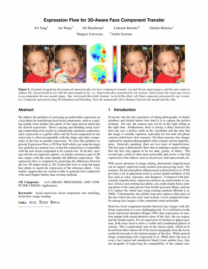
Figure 1: Example of applying the proposed expression flow for face component transfer. (a) and (b) are input images, and the user wants toreplace the closed mouth in (a) with the open mouth in (b). (c). Expression flow generated by our system, which warps the entire face in (a)to accommodate the new mouth shape. Top: horizontal flow field, bottom: vertical flow filed. (d) Final composite generated by our system.(e). Composite generated using 2D alignment and blending. Note the unnaturally short distance between the mouth and the chin.
Abstract
We address the problem of correcting an undesirable expression ona face photo by transferring local facial components, such as a smil-ing mouth, from another face photo of the same person which hasthe desired expression. Direct copying and blending using exist-ing compositing tools results in semantically unnatural composites,since expression is a global effect and the local component in oneexpression is often incompatible with the shape and other compo-nents of the face in another expression. To solve this problem wepresent Expression Flow, a 2D flow field which can warp the targetface globally in a natural way, so that the warped face is compatiblewith the new facial component to be copied over. To do this, start-ing with the two input face photos, we jointly construct a pair of 3Dface shapes with the same identity but different expressions. Theexpression flow is computed by projecting the difference betweenthe two 3D shapes back to 2D. It describes how to warp the targetface photo to match the expression of the reference photo. Userstudies suggest that our system is able to generate face compositeswith much higher fidelity than existing methods.
CR Categories: I.4.9 [IMAGE PROCESSING AND COM-PUTER VISION]: Applications
Keywords: facial expression, facial component, face modeling,facial flow, image warping
Links: DL PDF WEB
1 Introduction
Everyone who has the experience of taking photographs of familymembers and friends knows how hard it is to capture the perfectmoment. For one, the camera may not be at the right setting atthe right time. Furthermore, there is always a delay between thetime one sees a perfect smile in the viewfinder and the time thatthe image is actually captured, especially for low-end cell phonecameras which have slow response. For these reasons, face imagescaptured by amateur photographers often contain various imperfec-tions. Generally speaking, there are two types of imperfections.The first type is photometric flaws due to improper camera settings,thus the face may appear to be too dark, grainy, or blurry. Thesecond type, which is often more noticeable and severe, is the badexpression of the subject, such as closed eyes, half-open mouth, etc.
With recent advances in image editing, photometric imperfectionscan be largely improved using modern post-processing tools. Forinstance, the personal photo enhancement system [Joshi et al. 2010]provides a set of adjustment tools to correct global attributes of theface such as color, exposure, and sharpness. Compared with pho-tometric imperfections, expression artifacts are much harder to cor-rect. Given a non-smiling face photo, one could simply find a smil-ing photo of the same person from his/her personal album, and useit to replace the whole face using existing methods [Bitouk et al.2008]. Unfortunately, this global swap also replaces other parts ofthe face which the user may want to keep. Local component trans-fer among face images is thus sometimes more preferable.
However, local component transfer between face images with dif-ferent expressions is a very challenging task. It is well known in thefacial expression literature [Faigin 1991] that expressions of emo-tion engage both signal-intensive areas of the face: the eye region,and the mouth region. For an expression of emotion to appear gen-uine, both areas need to show a visible and coordinated pattern ofactivity. This is particularly true of the sincere smile, which in itsbroad form alters almost all of the facial topography from the lowereyelid downwards to the bottom margin of the face. While generalimage compositing tools [Agarwala et al. 2004] allow the user tocrop a face region and seamlessly blend it into another face, theyare incapable of improving the compatibility of the copied com-

ponent and the target face, as the example shown in Figure 1. Toreplace the closed mouth in Figure 1a with an open one in Fig-ure 1b, a straightforward solution is to crop the mouth region, applyadditional alignment adjustments, and seamlessly blend it into thetarget face. However, the resulting composite is semantically veryunnatural (Figure 1e). This is because, when the mouth opens, theshape of the whole lower-half of the face deforms accordingly. Toour best knowledge there are no existing tools that automaticallyhandle these deformations for creating realistic facial composites.
We address this problem by presenting Expression Flow, a 2D flowfield applied on the target image to deform the face in such a waythat it becomes compatible with the facial component to be copiedover. To compute the expression flow we first reconstruct a 3D faceshape for each image using a dataset of other people’s face shapes.Unlike traditional 3D fitting which tries to minimize the fitting er-ror on each image, we jointly reconstruct a pair of 3D shapes, whichhave the same identity, but with different expressions that match ourinput image pair. This is formulated as an optimization problemwith the objective to minimize the fitting errors with a person iden-tity constraint. A 3D flow is then computed from the pair of aligned3D shapes, and projected to 2D to form the 2D expression flow. Theshapes are also used to warp the 3D pose of the new component be-fore blending in. Due to the identity constraint, the expression flowreflects changes mainly due to differences of expression, and candeform the face in a natural way, as shown in Figure 1d.
Our expression flow is a hybrid of 3D and 2D methods. On the onehand, we rely on rough 3D shapes to compute the expression differ-ence between faces with different poses. Since typical expressionflows contain much lower level of detail (frequencies) than typicalappearance details, we found that our rough 3D reconstruction isadequate for the purpose of expression transfer. On the other hand,we rely on 2D methods to warp face images and transfer local de-tails between them. Our system thus has a greater flexibility and awider application range than previous 3D and 2D expression trans-fer methods (see Section 2).
Based on the proposed expression flow we develop an efficient facecompositing tool. To evaluate the effectiveness and generality of theproposed system, we conducted a comprehensive user study. Theresults suggest that the face composites created by our system havemuch higher fidelity than those generated by previous methods.
2 Related Work
Our work is related to previous research on face editing, facial ex-pression mapping, face alignment, 3D shape fitting and image com-positing.
Face Image Editing. Face image enhancement has been the sub-ject of extensive work. Earlier approaches use generic face imagesas training data for applications such as super-resolution [Liu et al.2007] and attractiveness enhancement by global face warping [Ley-vand et al. 2008]. Recently Joshi et al. [2010] proposed a systemto adjust global attributes such as tone, sharpness and lighting ofa face image using personal priors. Blanz et al. [2004] fit a mor-phable 3D model to a face image, and then render a new face usingthe same pose and illumination to replace it. The face swappingsystem [Bitouk et al. 2008] achieves a similar goal by construct-ing and using a large face image library. A real-time system forretrieving and replacing a face photo based on expression and posesimilarity was shown in [Shlizerman et al. 2010]. All these systemstarget global face editing. However replacing an entire head or faceis often not desired for personal photo editing, global warping doesnot handle large topology and appearance changes, and generat-ing realistic textured head models and compositing them into exist-ing photos remains a challenging problem. Our method combines
global warping and local compositing of face parts for an effectiveby-example expression editing.
Expression Mapping. There is also a large body of work ontransferring expressions between images, which falls into two cate-gories: 3D methods and 2D approaches. 3D approaches, such as theexpression synthesis system proposed by Pighin et al. [1998] andthe face reanimating system proposed by Blanz et al. [2003], try tocreate photorealistic textured 3D facial models from photographsor video. Once these models are constructed, they can be used forexpression interpolation. However, creating fully textured 3D mod-els is not trivial. In order to achieve photorealism the system has tomodel all facial components accurately such as the eyes, teeth, earsand hair, which is computationally expensive and unstable. Thesesystems thus can only work with high resolution face images shotin controlled indoor environments, and unlike our system, are notrobust enough to be used on day-to-day personal face photos.
2D expression mapping methods [Williams 1990] extract facial fea-tures from two images with different expressions, compute the fea-ture difference vectors and use them to guide image warping. Liuet al. [2001] propose an expression ratio image which captures boththe geometric changes and the expression details such as wrinkles.However, due to the lack of 3D information, these methods cannotdeal with faces from different view points. Most importantly, thesemethods alone cannot synthesize features that are not in the originalimage, such as opening a mouth.
Facial Feature Localization. Various techniques have been pro-posed for facial feature localization on images as well as invideo [Decarlo and Metaxas 2000]. Most of them combine localfeature detectors with global geometric constraints. The widely-used Active Shape Model [Cootes et al. 1995] learns statistical dis-tributions of feature points, thus allowing shapes to vary only inways seen in a training set. Active Appearance Models [Cooteset al. 2001] explore image intensity distributions for constrainingthe face shape. Pictorial structure methods [Felzenszwalb and Hut-tenlocher 2005] localize features by maximizing the posterior prob-ability for both appearance and shape. Recent work in this fieldalso includes component-based discriminative search [Liang et al.2008], and a subspace-constrained mean shift method [Saragihet al. 2009].
3D Shape Fitting. Recovering the 3D face shape from a single im-age is a key component in many 3D-based face processing systems.Blanz and Vetter [1999] optimize the parameters of a 3D morphablemodel by gradient descent in order to render an image that is asclose as possible to the input image. Romdhani and Vetter [2003]extend the inverse compositional image alignment algorithm to 3Dmorphable models. Shape-from-shading approaches are also ap-plied to 3D face reconstruction [Dovgard and Basri 2004; Shlizer-man and Basri 2011]. Kemelmacher-Shlizerman et al. [2010] showhow to find similarities in expression under different poses, and usea 3D-aware warping of facial features to compensate for pose dif-ferences.
Image Compositing. General image compositing tools such asthe photomontage system [Agarwala et al. 2004] and the instantcloning system [Farbman et al. 2009] allow image regions frommultiple sources to be seamlessly blended together, either by Pois-son blending [Perez et al. 2003] or using barycentric coordinates.Sunkavalli et al. [2010] propose a harmonization technique whichallows more natural composites to be created.

Target
Reference
2D Alignment
Joint 3D Fitting
Expression Warp
3D Rotation
Define Crop Region Final Blending
Figure 2: The flow chart of our system.
3 Our System
3.1 System Overview
Figure 2 shows the flow chart of the proposed system. Given atarget face image which the user wants to improve, and a referenceimage which contains the desired feature to be copied over, our sys-tem first uses computer vision techniques to automatically extractfacial feature points on both images. Based on the extracted featurepoints, we then jointly reconstruct 3D face shapes for both imagesusing a 3D face expression dataset. Our 3D fitting algorithm makessure that the two shapes have the same identity, thus the main dif-ference between them is due to changes in expression. We thencompute a 3D flow by subtracting the two shapes and project it to2D to create the expression flow. The expression flow is used towarp the target face. We also use the 3D shapes to align in 3Dthe reference face to the target face. The user then specifies the re-gion of the facial feature to be transferred, which is then seamlesslyblended into the target image to create the final composite.
3.2 Single Image Fitting
We first describe how to fit a 3D face shape to a single face image.Given the input image, the facial landmarks are first localized us-ing Active Shape Model (ASM) [Cootes et al. 1995], a robust facialfeature localization method. Following Milborrow and Nicolls’sapproach [2008], we localize 68 feature points, as shown in Fig-ure 2.
We represent the 3D geometry of a face with a shape vector s =(x1, y1, z1, · · · , xn, yn, zn)T that contains X,Y, Z coordinates ofits n vertices. Following Blanz and Vetter’s work [1999], we de-fine a morphable face model using Principal Component Analysis(PCA) on the training dataset. Denote the eigenvectors as vi, eigen-values as λi, and the mean shape as s, a new shape can be generatedfrom the PCA model as:
snew = s+∑
βivi = s+ V · β. (1)
The 3D fitting is performed by varying the coefficients β in order tominimize the error between the projections of the pre-defined land-marks on the 3D face geometry, and the 2D feature points detectedby ASM. We apply a weak perspective projection model, and definethe fitting energy for the kth landmark as:
Ek =1
2||R · (s(k) + V(k) · β)−X(k)||2, (2)
where R is the 2 by 3 projection matrix, V(k) is the sub-matrixof V consisting of the three rows that corresponding to X,Y, Zcoordinates of the kth landmark. X(k) = (x(k), y(k))T is X,Ycoordinates of the kth landmark detected from the face image.
Assuming a Gaussian distribution of the training data, the probabil-ity for coefficients β is given by:
p(β) ∼ exp[−1
2
∑(βi/λi)
2]. (3)
Let Λ = diag(λ21, λ
22, · · · , λ2
L). We define the energy of coeffi-cients as:
Ecoef =1
2· βTΛ−1β. (4)
The total energy function to be minimized is thus the combinationof the two terms:
E =∑
wkEk + c · Ecoef , (5)
where c is a parameter controlling the tradeoff between the fittingaccuracy and the shape fidelity, which is set to 5 × 10⁶ in our sys-tem. wk is the weight for the kth landmark. In our system we setwk = 0.5 for landmarks of eyebrows, since our training shapes aretextureless and these landmarks are hard to be labeled accurately.We empirically set wk = 2 for contour points, wk = 3 for mouthpoints, and wk = 1 for all other points.
To minimize E, we set∇βE = 0, which leads to:
β = P−1Q, (6)
where
P =∑
wk(RV(k))TRV(k) + cΛ−1, (7)
Q =∑
wk(RV(k))T (X(k) −Rs(k)). (8)
The above closed-form solution assumes that we know V (k), the3D vertices corresponding to the k-th landmark. For landmarkslocated inside the face region we can simply hard-code the corre-sponding 3D vertex. However, landmarks along the face contourdo not have a single corresponding vertex; they must be matchedwith 3D vertices along the face silhouette. We therefore employ atwo-stage optimization approach to find the optimal β. In the firststage we find the correspondences between vertices and landmarksby projecting the vertices onto the image plane, finding their convex
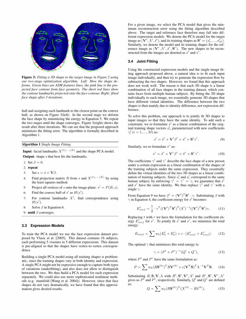
Figure 3: Fitting a 3D shape to the target image in Figure 2 usingour two-stage optimization algorithm. Left: How the shape de-forms. Green lines are ASM features lines, the pink line is the pro-jected face contour from face geometry. The short red lines showthe contour landmarks projected onto the face contour. Right: fittedface shape after 3 iterations.
hull and assigning each landmark to the closest point on the convexhull, as shown on Figure 3(left). In the second stage we deformthe face shape by minimizing the energy in Equation 5. We repeatthe two stages until the shape converges. Figure 3(right) shows theresult after three iterations. We can see that the proposed approachminimizes the fitting error. The algorithm is formally described inAlgorithm 1.
Algorithm 1 Single Image Fitting
Input: facial landmarks X(1),···,(K) and the shape PCA model.Output: shape s that best fits the landmarks.
1: Set β = 0.2: repeat3: Set s = s+ Vβ.
4: Find projection matrix R from s and X(1),···,(K) by usingthe least squares method.
5: Project all vertices of s onto the image plane: s′ = P (R, s).6: Find the convex hull of s′ as H(s′).
7: For contour landmarks Xi, find correspondence usingH(s′).
8: Solve β in Equation 6.9: until β converges.
3.3 Expression Models
To train the PCA model we use the face expression dataset pro-posed by Vlasic et al. [2005]. This dataset contains 16 subjects,each performing 5 visemes in 5 different expressions. This datasetis pre-aligned so that the shapes have vertex-to-vertex correspon-dence.
Building a single PCA model using all training shapes is problem-atic, since the training shapes vary in both identity and expression.A single PCA might not be expressive enough to capture both typesof variations (underfitting), and also does not allow to distinguishbetween the two. We thus build a PCA model for each expressionseparately. We could also use more sophisticated nonlinear meth-ods (e.g. manifold [Wang et al. 2004]). However, since that faceshapes do not vary dramatically, we have found that this approxi-mation gives desired results.
For a given image, we select the PCA model that gives the min-imum reconstruction error using the fitting algorithm describedabove. The target and reference face therefore may fall into dif-ferent expression models. We denote the PCA model for the targetimage as (Vt,Λt, st), and its training shapes as St = (st1, ..., s
tM ).
Similarly, we denote the model and its training shapes for the ref-erence image as (Vr,Λr, sr,Sr). The new shapes to be recon-structed from the images are denoted as st and sr .
3.4 Joint Fitting
Using the constructed expression models and the single image fit-ting approach proposed above, a natural idea is to fit each inputimage individually, and then try to generate the expression flow bysubtracting the two shapes. However, we found that this approachdoes not work well. The reason is that each 3D shape is a linearcombination of all face shapes in the training dataset, which con-tains faces from multiple human subjects. By fitting the 3D shapeindividually to each image, we essentially generate 3D shapes thathave different virtual identities. The difference between the twoshapes is then mainly due to identity difference, not expression dif-ference.
To solve this problem, our approach is to jointly fit 3D shapes toinput images so that they have the same identity. To add such aconstraint, we re-formulate st as a linear combination of the orig-inal training shape vectors sti , parameterized with new coefficientsγti (i = 1, ...,M ) as:
st = st + Vtβt = st + Stγt. (9)
Similarly, we re-formulate sr as:
sr = sr + Vrβr = sr + Srγr. (10)
The coefficients γt and γr describe the face shape of a new personunder a certain expression as a linear combination of the shapes ofthe training subjects under the same expression. They essentiallydefine the virtual identities of the two 3D shapes as a linear combi-nation of training subjects. Since sti and sri correspond to the samehuman subject, by enforcing γt = γr = γ, we guarantee that st
and sr have the same identity. We thus replace γt and γr with asingle γ.
From Equation 9 we have βt = (Vt)TSt · γ. Substituting β withγ in Equation 4, the coefficient energy for st becomes:
Etcoef =1
2· γT ((Vt)TSt)T (Λt)−1((Vt)TSt)γ. (11)
Replacing t with r we have the formulation for the coefficient en-ergy Ercoef for sr . To jointly fit st and sr , we minimize the totalenergy:
Etotal =∑
wk(Etk + Erk) + c · (Etcoef + Ercoef ). (12)
The optimal γ that minimizes this total energy is:
γ = (P t + P r)−1(Qt +Qr), (13)
where P t and P r have the same formulation as:
P =∑
wk(RS(k))TRV(k) + c(VTS)TΛ−1VTS. (14)
Substituting R,S,V,Λ with Rt,St,Vt,Λt and Rr,Sr,Vr,Λr
gives us P t and P r , respectively. Similarly, Qt and Qr are definedas:
Q =∑
wk(RS(k))T (X(k) −Rs(k)), (15)
and substituting R,S, X, s with Rt,St, Xt, st and Rr,Sr, Xr, sr
gives us the formulation for Qt and Qr .
The joint fitting algorithm is formally described as follows:
Algorithm 2 Joint Fitting
Input: facial landmarks of two images, and all PCA models.Output: shapes st and sr that jointly fit the landmarks on both
images.
1: Apply Algorithm 1 to each image to determine their expressionmodels V t and V r , as in Section 3.3.
2: Set γ = 0.3: repeat4: Set st = st + Stγ and sr = sr + Srγ.5: For each image, apply step 4-7 in Algorithm 1.6: Solve the common γ in Equation 13.7: until γ converges.
3.5 Computing 2D Flow
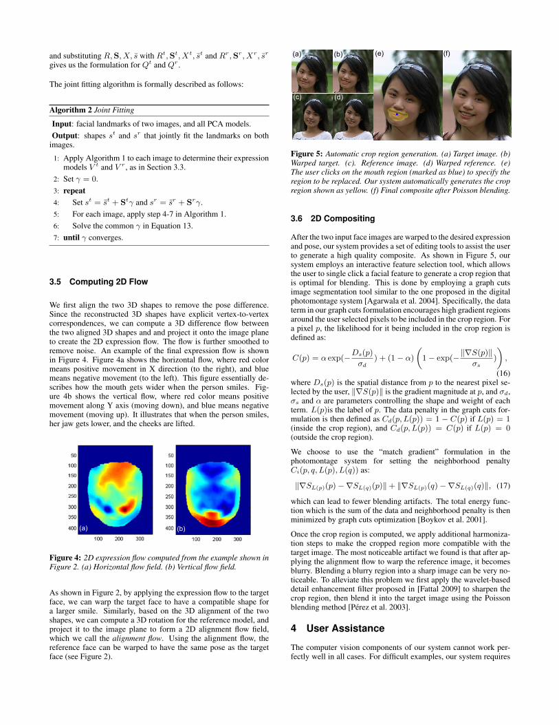
We first align the two 3D shapes to remove the pose difference.Since the reconstructed 3D shapes have explicit vertex-to-vertexcorrespondences, we can compute a 3D difference flow betweenthe two aligned 3D shapes and and project it onto the image planeto create the 2D expression flow. The flow is further smoothed toremove noise. An example of the final expression flow is shownin Figure 4. Figure 4a shows the horizontal flow, where red colormeans positive movement in X direction (to the right), and bluemeans negative movement (to the left). This figure essentially de-scribes how the mouth gets wider when the person smiles. Fig-ure 4b shows the vertical flow, where red color means positivemovement along Y axis (moving down), and blue means negativemovement (moving up). It illustrates that when the person smiles,her jaw gets lower, and the cheeks are lifted.
(a) (b)
Figure 4: 2D expression flow computed from the example shown inFigure 2. (a) Horizontal flow field. (b) Vertical flow field.
As shown in Figure 2, by applying the expression flow to the targetface, we can warp the target face to have a compatible shape fora larger smile. Similarly, based on the 3D alignment of the twoshapes, we can compute a 3D rotation for the reference model, andproject it to the image plane to form a 2D alignment flow field,which we call the alignment flow. Using the alignment flow, thereference face can be warped to have the same pose as the targetface (see Figure 2).
(a) (b)
(d)
(e) (f)
(c)
Figure 5: Automatic crop region generation. (a) Target image. (b)Warped target. (c). Reference image. (d) Warped reference. (e)The user clicks on the mouth region (marked as blue) to specify theregion to be replaced. Our system automatically generates the cropregion shown as yellow. (f) Final composite after Poisson blending.
3.6 2D Compositing
After the two input face images are warped to the desired expressionand pose, our system provides a set of editing tools to assist the userto generate a high quality composite. As shown in Figure 5, oursystem employs an interactive feature selection tool, which allowsthe user to single click a facial feature to generate a crop region thatis optimal for blending. This is done by employing a graph cutsimage segmentation tool similar to the one proposed in the digitalphotomontage system [Agarwala et al. 2004]. Specifically, the dataterm in our graph cuts formulation encourages high gradient regionsaround the user selected pixels to be included in the crop region. Fora pixel p, the likelihood for it being included in the crop region isdefined as:
C(p) = α exp(−Ds(p)σd
) + (1− α)
(1− exp(−‖∇S(p)‖
σs)
),
(16)where Ds(p) is the spatial distance from p to the nearest pixel se-lected by the user, ‖∇S(p)‖ is the gradient magnitude at p, and σd,σs and α are parameters controlling the shape and weight of eachterm. L(p)is the label of p. The data penalty in the graph cuts for-mulation is then defined as Cd(p, L(p)) = 1 − C(p) if L(p) = 1(inside the crop region), and Cd(p, L(p)) = C(p) if L(p) = 0(outside the crop region).
We choose to use the “match gradient” formulation in thephotomontage system for setting the neighborhood penaltyCi(p, q, L(p), L(q)) as:
‖∇SL(p)(p)−∇SL(q)(p)‖+ ‖∇SL(p)(q)−∇SL(q)(q)‖, (17)
which can lead to fewer blending artifacts. The total energy func-tion which is the sum of the data and neighborhood penalty is thenminimized by graph cuts optimization [Boykov et al. 2001].
Once the crop region is computed, we apply additional harmoniza-tion steps to make the cropped region more compatible with thetarget image. The most noticeable artifact we found is that after ap-plying the alignment flow to warp the reference image, it becomesblurry. Blending a blurry region into a sharp image can be very no-ticeable. To alleviate this problem we first apply the wavelet-baseddetail enhancement filter proposed in [Fattal 2009] to sharpen thecrop region, then blend it into the target image using the Poissonblending method [Perez et al. 2003].
4 User Assistance
The computer vision components of our system cannot work per-fectly well in all cases. For difficult examples, our system requires
(c)(b)(a)
(d) (e) (f)
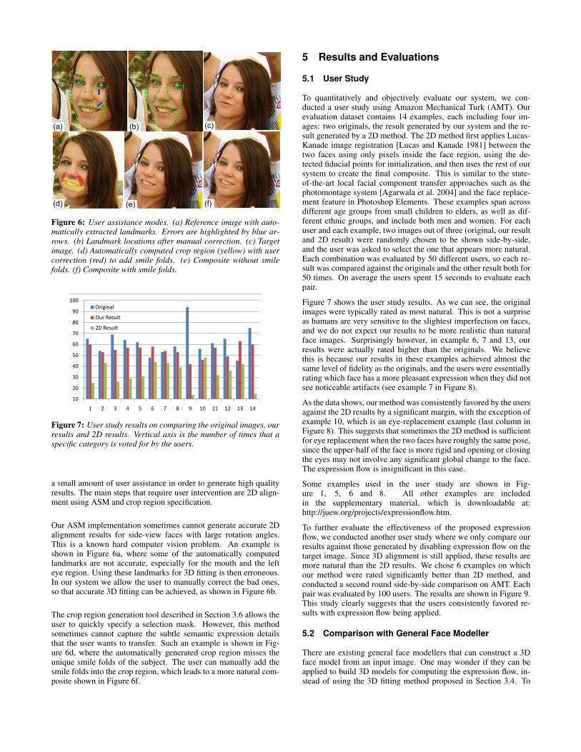
Figure 6: User assistance modes. (a) Reference image with auto-matically extracted landmarks. Errors are highlighted by blue ar-rows. (b) Landmark locations after manual correction. (c) Targetimage. (d) Automatically computed crop region (yellow) with usercorrection (red) to add smile folds. (e) Composite without smilefolds. (f) Composite with smile folds.
65 60 25 15054 53 43 15069 55 26 15064 57 29 15062 57 31 15048 58 44 15053 54 43 15058 53 39 15094 42 14 15056 46 48 15061 57 32 15065 49 36 15045 63 42 15075 60 15 150
22 3825 25
10
20
30
40
50
60
70
80
90
100
1 2 3 4 5 6 7 8 9 10 11 12 13 14
Original
Our Result
2D Result
Figure 7: User study results on comparing the original images, ourresults and 2D results. Vertical axis is the number of times that aspecific category is voted for by the users.
a small amount of user assistance in order to generate high qualityresults. The main steps that require user intervention are 2D align-ment using ASM and crop region specification.
Our ASM implementation sometimes cannot generate accurate 2Dalignment results for side-view faces with large rotation angles.This is a known hard computer vision problem. An example isshown in Figure 6a, where some of the automatically computedlandmarks are not accurate, especially for the mouth and the lefteye region. Using these landmarks for 3D fitting is then erroneous.In our system we allow the user to manually correct the bad ones,so that accurate 3D fitting can be achieved, as shown in Figure 6b.
The crop region generation tool described in Section 3.6 allows theuser to quickly specify a selection mask. However, this methodsometimes cannot capture the subtle semantic expression detailsthat the user wants to transfer. Such an example is shown in Fig-ure 6d, where the automatically generated crop region misses theunique smile folds of the subject. The user can manually add thesmile folds into the crop region, which leads to a more natural com-posite shown in Figure 6f.
5 Results and Evaluations
5.1 User Study
To quantitatively and objectively evaluate our system, we con-ducted a user study using Amazon Mechanical Turk (AMT). Ourevaluation dataset contains 14 examples, each including four im-ages: two originals, the result generated by our system and the re-sult generated by a 2D method. The 2D method first applies Lucas-Kanade image registration [Lucas and Kanade 1981] between thetwo faces using only pixels inside the face region, using the de-tected fiducial points for initialization, and then uses the rest of oursystem to create the final composite. This is similar to the state-of-the-art local facial component transfer approaches such as thephotomontage system [Agarwala et al. 2004] and the face replace-ment feature in Photoshop Elements. These examples span acrossdifferent age groups from small children to elders, as well as dif-ferent ethnic groups, and include both men and women. For eachuser and each example, two images out of three (original, our resultand 2D result) were randomly chosen to be shown side-by-side,and the user was asked to select the one that appears more natural.Each combination was evaluated by 50 different users, so each re-sult was compared against the originals and the other result both for50 times. On average the users spent 15 seconds to evaluate eachpair.
Figure 7 shows the user study results. As we can see, the originalimages were typically rated as most natural. This is not a surpriseas humans are very sensitive to the slightest imperfection on faces,and we do not expect our results to be more realistic than naturalface images. Surprisingly however, in example 6, 7 and 13, ourresults were actually rated higher than the originals. We believethis is because our results in these examples achieved almost thesame level of fidelity as the originals, and the users were essentiallyrating which face has a more pleasant expression when they did notsee noticeable artifacts (see example 7 in Figure 8).
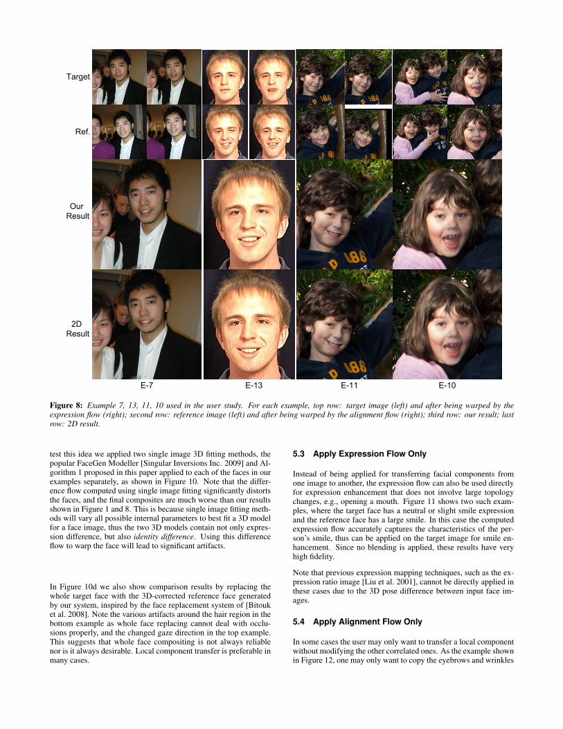
As the data shows, our method was consistently favored by the usersagainst the 2D results by a significant margin, with the exception ofexample 10, which is an eye-replacement example (last column inFigure 8). This suggests that sometimes the 2D method is sufficientfor eye replacement when the two faces have roughly the same pose,since the upper-half of the face is more rigid and opening or closingthe eyes may not involve any significant global change to the face.The expression flow is insignificant in this case.
Some examples used in the user study are shown in Fig-ure 1, 5, 6 and 8. All other examples are includedin the supplementary material, which is downloadable at:http://juew.org/projects/expressionflow.htm.
To further evaluate the effectiveness of the proposed expressionflow, we conducted another user study where we only compare ourresults against those generated by disabling expression flow on thetarget image. Since 3D alignment is still applied, these results aremore natural than the 2D results. We chose 6 examples on whichour method were rated significantly better than 2D method, andconducted a second round side-by-side comparison on AMT. Eachpair was evaluated by 100 users. The results are shown in Figure 9.This study clearly suggests that the users consistently favored re-sults with expression flow being applied.
5.2 Comparison with General Face Modeller
There are existing general face modellers that can construct a 3Dface model from an input image. One may wonder if they can beapplied to build 3D models for computing the expression flow, in-stead of using the 3D fitting method proposed in Section 3.4. To
E-7 E-13 E-11 E-10
2DResult
OurResult
Target
Ref.
Figure 8: Example 7, 13, 11, 10 used in the user study. For each example, top row: target image (left) and after being warped by theexpression flow (right); second row: reference image (left) and after being warped by the alignment flow (right); third row: our result; lastrow: 2D result.
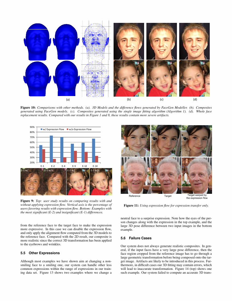
test this idea we applied two single image 3D fitting methods, thepopular FaceGen Modeller [Singular Inversions Inc. 2009] and Al-gorithm 1 proposed in this paper applied to each of the faces in ourexamples separately, as shown in Figure 10. Note that the differ-ence flow computed using single image fitting significantly distortsthe faces, and the final composites are much worse than our resultsshown in Figure 1 and 8. This is because single image fitting meth-ods will vary all possible internal parameters to best fit a 3D modelfor a face image, thus the two 3D models contain not only expres-sion difference, but also identity difference. Using this differenceflow to warp the face will lead to significant artifacts.
In Figure 10d we also show comparison results by replacing thewhole target face with the 3D-corrected reference face generatedby our system, inspired by the face replacement system of [Bitouket al. 2008]. Note the various artifacts around the hair region in thebottom example as whole face replacing cannot deal with occlu-sions properly, and the changed gaze direction in the top example.This suggests that whole face compositing is not always reliablenor is it always desirable. Local component transfer is preferable inmany cases.
5.3 Apply Expression Flow Only
Instead of being applied for transferring facial components fromone image to another, the expression flow can also be used directlyfor expression enhancement that does not involve large topologychanges, e.g., opening a mouth. Figure 11 shows two such exam-ples, where the target face has a neutral or slight smile expressionand the reference face has a large smile. In this case the computedexpression flow accurately captures the characteristics of the per-son’s smile, thus can be applied on the target image for smile en-hancement. Since no blending is applied, these results have veryhigh fidelity.
Note that previous expression mapping techniques, such as the ex-pression ratio image [Liu et al. 2001], cannot be directly applied inthese cases due to the 3D pose difference between input face im-ages.
5.4 Apply Alignment Flow Only
In some cases the user may only want to transfer a local componentwithout modifying the other correlated ones. As the example shownin Figure 12, one may only want to copy the eyebrows and wrinkles
(a) (b) (c) (d)
Figure 10: Comparisons with other methods. (a). 3D Models and the difference flows generated by FaceGen Modeller. (b). Compositesgenerated using FaceGen models. (c). Composites generated using the single image fitting algorithm (Algorithm 1). (d). Whole facereplacement results. Compared with our results in Figure 1 and 8, these results contain more severe artifacts.
20%
30%
40%
50%
60%
70%
80%
90%
E-1 E-2 E-4 E-5 E-12 E-14
w/ Expression Flow w/o Expression Flow
E-1:w/ E-1:w/o E-2:w/ E-2:w/o
Figure 9: Top: user study results on comparing results with andwithout applying expression flow. Vertical axis is the percentage ofusers favoring results with expression flow. Bottom: Examples withthe most significant (E-2) and insignificant (E-1) differences.
from the reference face to the target face to make the expressionmore expressive. In this case we can disable the expression flow,and only apply the alignment flow computed from the 3D models tothe reference face. Compared with the 2D result, our composite ismore realistic since the correct 3D transformation has been appliedto the eyebrows and wrinkles.
5.5 Other Expressions
Although most examples we have shown aim at changing a non-smiling face to a smiling one, our system can handle other lesscommon expressions within the range of expressions in our train-ing data set. Figure 13 shows two examples where we change a
TargetReference Target warped by the expression flow
Figure 11: Using expression flow for expression transfer only.
neutral face to a surprise expression. Note how the eyes of the per-son changes along with the expression in the top example, and thelarge 3D pose difference between two input images in the bottomexample.
5.6 Failure Cases
Our system does not always generate realistic composites. In gen-eral, if the input faces have a very large pose difference, then theface region cropped from the reference image has to go through alarge geometric transformation before being composed onto the tar-get image. Artifacts are likely to be introduced in this process. Fur-thermore, in difficult cases our 3D fitting may contain errors, whichwill lead to inaccurate transformation. Figure 14 (top) shows onesuch example. Our system failed to compute an accurate 3D trans-

Target
Reference
Our Result 2D Result
Figure 12: An example of creating composite without applying ex-pression flow. Eyebrows and wrinkles are transferred from the ref-erence to the target image. Note the right eyebrow in the resultimages.
Target Reference Our Result
Figure 13: Changing a neutral expression to a surprise expression.
formation for the mouth region, thus in the result the mouth regionis clearly not compatible with the pose and shape of the target face,although our result is still significantly better than the 2D result. Toavoid this problem one can find another reference image where theface pose is closer to that of the target face. This is not a problem ifa large personal photo album of the subject is available.
Figure 14(bottom) shows another limitation of our system on han-dling asymmetric expressions. For this expression transfer exam-ple, our system cannot raise one eyebrow and at the same timelower the other one. This is because our training dataset containsonly symmetric expressions. Using a richer training dataset willhelp in this case.
5.7 Computational Efficiency
We found that the iterative joint fitting algorithm (Algorithm 2) con-verges fast in practice. In our experiments we use only 10 iterations,each being a closed-form solution. In our Matlab implementation,it takes less than one second to run the algorithm. Our approachis also robust to local minima for two reasons. First, although weuse an alternating minimization approach, in each stage we havea closed-form solution to efficiently minimize the energy in thatstage. Second, we found that our initialization by aligning the 3Dshapes to the images using internal facial landmarks, is accurateenough and leads to a quick convergence in all our examples.
Target
Reference
Our Result 2D Result
Reference Target Our Result
Figure 14: Two failure examples. Top: an unsuccessful composit-ing. Bottom: an unsuccessful expression transfer.
6 Conclusion and Future Work
In this paper we address the problem of transferring local facialcomponents between face images with different expressions of thesame person. To account for the expression difference, we proposea novel expression flow, a 2D flow field which can warp the targetface in a natural way so that the warped face becomes compatiblewith the new component to be blended in. The expression flowis computed from a novel joint 3D fitting method, which jointlyreconstructs 3D face shapes from the two input images, so that theidentity difference between them is minimized, and only expressiondifference exists. A comprehensive user study was conducted todemonstrate the effectiveness of our system.
Currently our system relies on the user to provide the reference im-age for improving the target image. In the future we plan to de-velop a reference image search tool, which can automatically iden-tify good reference images to use given the target image, in thepersonal photo album of the subject. This will greatly improve theefficiency of the personal face editing workflow.
Our system currently uses the face expression dataset collected byVlasic et al. [2005]. While we demonstrate in this paper that oursystem can work reliably well on a wide variety of people of differ-ent races, ages and genders, we are also aware that the dataset is notrich enough to handle all possible expressions, especially asymmet-ric ones. As future work we plan to use existing 3D face capturingmethods [Zhang et al. 2004; Wang et al. 2004] to capture more datato enrich our dataset, and explore whether it can boost the perfor-mance of the system.
As pointed out by some user study subjects, some of our results stillcontain minor but noticeable photometric artifacts. For instance,some subjects pointed out that the mouth region shown in Example14, Figure 8 is grainy. While fixing these blending artifacts is notthe main focus of this paper, we plan to incorporate more advancedharmonization methods [Sunkavalli et al. 2010] into our system tofurther improve the quality of the final results.
Acknowledgements
We would like to thank the anonymous reviewers for their helpfulfeedback. Fei Yang and Dimitris Metaxas are partially supported
by the following grants to Dimitris Metaxas: NSF-0549115, NSF-0725607, NASA-NSBRI-NBTS01601, NASA-NSBRI-NBTS004,ONR-N000140910104 and Adobe systems.
References
AGARWALA, A., DONTCHEVA, M., AGRAWALA, M., DRUCKER,S., COLBURN, A., CURLESS, B., SALESIN, D., AND COHEN,M. 2004. Interactive digital photomontage. In Proceedings ofACM SIGGRAPH, vol. 23, 294–302.
BITOUK, D., KUMAR, N., DHILLON, S., BELHUMEUR, P., ANDNAYAR, S. K. 2008. Face swapping: automatically replacingfaces in photographs. In Proceedings of ACM SIGGRAPH, 39:1–39:8.
BLANZ, V., AND VETTER, T. 1999. A morphable model for thesynthesis of 3d faces. In Proceedings of ACM SIGGRAPH, 187–194.
BLANZ, V., BASSO, C., POGGIO, T., AND VETTER. 2003. Rean-imating faces in images and video. Computer Graphics Forum22, 3.
BLANZ, V., SCHERBAUM, K., VETTER, T., AND SEIDEL, H.-P.2004. Exchanging faces in images. Computer Graphics Forum23, 3, 669–676.
BOYKOV, Y., VEKSLER, O., AND ZABIH, R. 2001. Fast approx-imate energy minimization via graph cuts. IEEE Trans. PatternAnalysis and Machine Intelligence 23.
COOTES, T., TAYLOR, C., COOPER, D., AND GRAHAM, J. 1995.Active shape models: Their training and application. ComputerVision and Image Understanding 61, 1, 38–59.
COOTES, T. F., EDWARDS, G. J., AND TAYLOR, C. J. 2001.Active appearance models. IEEE Trans. Pattern Analysis andMachine Intelligence 23, 681–685.
DECARLO, D., AND METAXAS, D. 2000. Optical flow constraintson deformable models with applications to face tracking. Int. J.Comput. Vision 38, 99–127.
DOVGARD, R., AND BASRI, R. 2004. Statistical symmetric shapefrom shading for 3d structure recovery of faces. In Proceedingsof ECCV, 99–113.
FAIGIN, G. 1991. The Artist’s Complete Guide to Facial Expres-sion. Watson-Guptill Publications Inc., New York.
FARBMAN, Z., HOFFER, G., LIPMAN, Y., COHEN-OR, D., ANDLISCHINSKI, D. 2009. Coordinates for instant image cloning.In Proceedings of ACM SIGGRAPH, vol. 28, 67:1–67:9.
FATTAL, R. 2009. Edge-avoiding wavelets and their applications.In Proceedings of ACM SIGGRAPH, vol. 28.
FELZENSZWALB, P. F., AND HUTTENLOCHER, D. P. 2005. Pic-torial structures for object recognition. International Journal ofComputer Vision 61, 55–79.
JOSHI, N., MATUSIK, W., ADELSON, E. H., AND KRIEGMAN,D. J. 2010. Personal photo enhancement using example images.ACM Trans. Graphics 29, 12:1–12:15.
LEYVAND, T., COHEN-OR, D., DROR, G., AND LISCHINSKI, D.2008. Data-driven enhancement of facial attractiveness. In Pro-ceedings of ACM SIGGRAPH, 38:1–38:9.
LIANG, L., XIAO, R., WEN, F., AND SUN, J. 2008. Face align-ment via component-based discriminative search. In Proceed-ings of ECCV.
LIU, Z., SHAN, Y., AND ZHANG, Z. 2001. Expressive expressionmapping with ratio images. In Proceedings of ACM SIGGRAPH,271–276.
LIU, C., SHUM, H.-Y., AND FREEMAN, W. T. 2007. Face halluci-nation: Theory and practice. International Journal of ComputerVision 75, 115–134.
LUCAS, B. D., AND KANADE, T. 1981. An iterative image reg-istration technique with an application to stereo vision. In Pro-ceedings of the 1981 DARPA Image Understanding Workshop,121–130.
MILBORROW, S., AND NICOLLS, F. 2008. Locating facial featureswith an extended active shape model. In Proceedings of ECCV,504–513.
PEREZ, P., GANGNET, M., AND BLAKE, A. 2003. Poisson imageediting. In Proceedings of ACM SIGGRAPH, 313–318.
PIGHIN, F., HECKER, J., LISCHINSKI, D., SZELISKI, R., ANDSALESIN, D. H. 1998. Synthesizing realistic facial expressionsfrom photographs. In Proceedings of ACM SIGGRAPH, 75–84.
ROMDHANI, S., AND VETTER, T. 2003. Efficient, robust and ac-curate fitting of a 3d morphable model. In Proceedings of ICCV,59–66.
SARAGIH, J., LUCEY, S., AND COHN, J. 2009. Face alignmentthrough subspace constrained mean-shifts. In Proceedings of the12th ICCV, 1034–1041.
SHLIZERMAN, I. K., AND BASRI, R. 2011. 3d face reconstructionfrom a single image using a single reference face shape. IEEETrans. Pattern Analysis and Machine Intelligence 33, 394–405.
SHLIZERMAN, I. K., SANKAR, A., SHECHTMAN, E., ANDSEITZ, S. M. 2010. Being john malkovich. In Proceedingsof ECCV, 341–353.
SINGULAR INVERSIONS INC. 2009. Facegen modeller manual. Inwww.facegen.com.
SUNKAVALLI, K., JOHNSON, M. K., MATUSIK, W., AND PFIS-TER, H. 2010. Multi-scale image harmonization. In Proceedingsof ACM SIGGRAPH, vol. 29.
VLASIC, D., BRAND, M., PFISTER, H., AND POPOVIC, J. 2005.Face transfer with multilinear models. In Proceedings of ACMSIGGRAPH, vol. 24, 426–433.
WANG, Y., HUANG, X., LEE, C.-S., ZHANG, S., LI, Z., SAMA-RAS, D., METAXAS, D., ELGAMMAL, A., AND HUANG, P.2004. High resolution acquisition, learning and transfer of dy-namic 3-d facial expressions. In Proceedings of EuroGraphics,677–686.
WILLIAMS, L. 1990. Performance-driven facial animation. InProceedings of ACM SIGGRAPH, vol. 24, 235–242.
ZHANG, L., SNAVELY, N., CURLESS, B., AND SEITZ, S. M.2004. Spacetime faces: High-resolution capture for modelingand animation. In Proceedings of ACM SIGGRAPH, 548–558.


![Toward a Generic and Concurrency -Aware Pipes & Filters ...€¦ · Toward a Generic and Concurrency -Aware Pipes & Filters Framework • ExplorViz‘ traceprocessing component [FWBH13]](https://static.fdocuments.net/doc/165x107/6044ddbb6d809731ea20e8cb/toward-a-generic-and-concurrency-aware-pipes-filters-toward-a-generic.jpg)