EXPLOSION PROTECTION: background, types of · PDF fileDefinitions (IEC 60079-10-1) •...
40
EXPLOSION PROTECTION: background, types of protection, intrinsic safety DTS0656-0
Transcript of EXPLOSION PROTECTION: background, types of · PDF fileDefinitions (IEC 60079-10-1) •...

EXPLOSION PROTECTION:
background,
types of protection,
intrinsic safety
DTS0656-0

Definitions (IEC 60079-10-1)
• Explosive atmosphere: mixture with air, under atmospheric
conditions, of flammable substances in the form of gas, vapour,
dust, fibres, or flyings which, after ignition, permits self-sustaining
propagation.
• Hazardous Area (gas): an area in which an explosive gas
atmosphere is or may be expected to be present, in quantities
such as to require special precautions for the construction,
installation and use of equipment.
Fire triangle Explosion pentagon

Groups, Categories, Zones, EPLs
Protection
levelPresence
Explosive
atmosphere
99/92/CE
(ATEX)94/9/CE (ATEX) IECEx
Area
classificationGroup
Eq.
CategoryGroup EPL
VERY HIGH
(two
independent
faults)
Long periods /
continuously
Coal mine - I M1 I Ma
Gas zone 0 II 1G II Ga
Dust zone 20 II 1D III Da
HIGH
(one fault)
Occasionally
during normal
operation
Coal mine - I M2 I Mb
Gas zone 1 II 2G II Gb
Dust zone 21 II 2D III Db
NORMAL
Not during
normal
operation
Gas zone 2 I 3G I Gc
Dust zone 22 II 3D II Dc
Area classification derived from IEC 60079-10-1 (for gas) and IEC 60079-10-2 (for dust).

Gas area classification
Area Classification: example

Dust area classification
Area Classification: example

Gas and Dust Groups
Place of use GroupRepresentative
substance
Mines susceptible to
firedampI methane
Surface industries
IIA propane
IIB ethylene
IIC hydrogen/acetylene
IIIA combustible flyings
IIIB non-conductive dust
IIIC conductive dust
D
A
N
G
E
R
D
A
N
G
E
R

Minimum Ignition Energy
Ignition energy vs. gas mixture concentration:
Minimum ignition energy:
I ≈ 320 µJ (methane)
IIA ≈ 180 µJ (propane)
IIB ≈ 60 µJ (ethylene)
IIC ≈ 20 µJ (hydrogen)
D
A
N
G
E
R
Graph taken from «North American Guide to Intrinsic Safety», Elcon Instruments

Temperature Class (gas)
Temperature
class (°C)
Max surface
temperature
Gas or vapour
(examples)
Ignition
temperature (°C)
T1 450
Methane (I)
Hydrogen (IIC)
Benzene (IIA)
595
560
496
T2 300Buthane (IIA)
Ethylbenzene (IIA)
372
431
T3 200Cyclohexane (IIA)
Heptane (IIA)
244
204
T4 135 Ethylether (IIB) 175
T5 100
T6 85 Carbon disulfide (IIC) 90
Data taken from IEC 60079-20-1 Ignition energy and ignition temperature are not mutually related!
D
A
N
G
E
R

Types of protection and Standards
Principle Denomination Concept Symbol Marking Standard
Segregation
Encapsulation «m»Ex ma; Ex mb;
Ex mcEN/IEC 60079-18
Oil immersion «o» Ex o EN/IEC 60079-6
Pressurization «p»Ex px; Ex py;
Ex pzEN/IEC 60079-2
Prevention
Increased safety «e» Ex e EN/IEC 60079-7
Intrinsic safety «i»Ex ia; Ex ib;
Ex icEN/IEC 60079-11
Containment Flameproof «d» Ex d EN/IEC 60079-1
Quenching Powder filling «q» Ex q EN/IEC 60079-5
Simplified Non incendive «n»Ex nA; Ex nC;
Ex nREN/IEC 60079-15

Encapsulation «Ex m»
Basic principle: segregation
Characteristics:
• good mechanical protection
• maintenance and/or reparation not
possible!
Applications:
• small size apparatus (transformers,
electrovalves, electronic sensors and
devices)

Oil immersion «Ex o»
Basic principle: segregation
Characteristics:
• oil with good isolating characteristics
• not favorable for small devices
Applications:
• power transformers
• motors
• contacts and moving electrical parts

Pressurization «Ex p»
Basic principle: segregation
Characteristics:
• no size limitation, but not favorable
for small devices
• safety related control necessary
• necessary when source of emission is
within apparatus (gas analyzers)
Applications:
• transformers
• big motors
• instrumentation panels
• analysis cabins and pressurized rooms

Increased safety «Ex e»
Basic principle: prevention
Characteristics:
• increased insulation materials
• degree of protection
• limited overtemperatures
Applications:
• terminal blocks
• coils
• motors and generators
• lighting appliances
• batteries and trace heating
resistances

Intrinsic safety «Ex i»
Basic principle: prevention
Characteristics:
• low power applications
• overrated components
• safety factors
• isolation distances
• need of barrier (system integrity)
Applications:
• electronic instruments
• measurement and control processes
• battery supplied devices
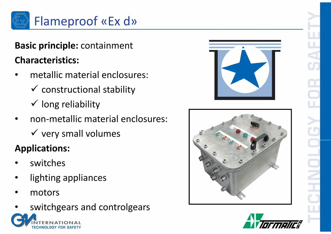
Flameproof «Ex d»
Basic principle: containment
Characteristics:
• metallic material enclosures:
� constructional stability
� long reliability
• non-metallic material enclosures:
� very small volumes
Applications:
• switches
• lighting appliances
• motors
• switchgears and controlgears

Powder filling «Ex q»
Basic principle: quenching
Characteristics:
• powder with good dielectric
characteristics (quarts/sand)
• enclosure withstanding pressure
Applications:
• power supplies
• traction batteries
• discrete sub-assemblies and
components inside other apparatus
(generally Ex e)

«Ex n»
Basic principle: various
Characteristics:
• only for normal operating conditions
• only for zone 2, EPL Gc
• Ex nA, Ex nC, Ex nR
Applications:
• motors
• lighting appliances
• terminal blocks
• single sparking devices (relays, bi-
metallic switches)

Historical Information
Mines were the first area taken into consideration for explosion risks
due to the presence of Griseous Gas and Carbon Dust.
An electrical spark could ignite the gas generating a primary
explosion which would create a secondary carbon dust explosion
propagating trough the mine with disastrous effects.
Already in the late 1800 beginning of the 1900 hundred low voltage
batteries were used in mines to prevent electrical spark.
But this was not a safe circuit.

«Safe» low voltage signaling system
Historical Information

After a 1913 huge mine
explosion in a Welsh mine that
left 439 dead miners, studies
begin until it was realized that
the energy accumulated in the
circuit Inductance and
Capacitance, even in a low
voltage system, could lead to a
large enough spark to ignite the
gaseous atmosphere present.
Historical Information

Historical Information
This studies lead to an energy limitation technique:
“Intrinsic Safety”.

Historical Information
Complete development of Intrinsic Safety market. Harmonization
of world standards. IEC Ex
Low use of Intrinsic Safety until the introduction of
semiconductor circuits. Development of National Standards
Extension of studies to cover surface industries substances
1° Certified Intrinsic Safety Apparatus
Energy Limitation as the fundament of Intrinsic Safety
Study on ignition mechanism in methane-air gas mixtures
2000
1970
1950
1930
1920
1910

Intrinsic safety is always implemented as a loop
Intrinsic Safety Loop

Entity Parameters
The use of an Isolator or a Barrier is not a sufficient condition to
achieve Safety in Hazardous Locations.
The system (loop) must be verified as a whole:
• Isolator / Barrier Certification in compliance with Area
• Field Device Certification in compliance with Area
• Safety parameters of Apparatus and Associated Apparatus must
match
• Cable length, its parameters, must be in compliance with
Associated Apparatus certificate

Entity Parameters
Associated Apparatus (Isolators/Barriers):
• Um Maximum allowed voltage on Safe Area Circuits
• Uo Maximum Open Circuit Voltage
• Io Maximum Short Circuit Current
• Po Maximum Transferable Power
• Co Maximum External Capacitance Allowed
• Lo Maximum External Inductance Allowed
• Lo/Ro Maximum Allowed External L/R Ratio

Entity Parameters
Apparatus (Field Instruments):
• Ui Maximum Allowed Open Circuit Voltage
• Ii Maximum Allowed Short Circuit Current
• Pi Maximum Allowed Power
• Ci Maximum Internal Capacitance
• Li Maximum Internal Inductance

Entity Parameters
Cable:
• Cc Cable Capacitance x Length (mt or km)
• Lc Cable Impedance x Length (mt or km)
• Lc/Rc Cable Impedance Vs. Resistance Ratio

Entity Parameters verification
http://www.gminternationalsrl.com/index.php?p=loop_check
THH200 G.M. D5014
Ui (30 V) > Uo (25.9 V)
Ii (130 mA) > Io (92 mA)
Pi (800 mW) > Po (594 mW)
Ci (0.005 µF) + Cc < Co (0.1 µF)
Li (0.5 mH) + Lc < Lo (4.2 mH)

Certification tools: Loop Verificator

Associated Apparatus
ZENER BARRIERS (Barriers):
Passive devices that use Zener Diodes to divert fault current to
ground.
ISOLATED BARRIERS (Isolators):
Active instruments that use Safety Isolation components, such as
transformers or opto-couplers, to keep a fault energy to pass from
Safe to Hazardous Location.

Zener barrier
I.S.
Circuit
Safety Ground
Current limiting resistor Zener Protecting Fuse
Voltage limiting Zeners
Safe AreaHaz. Area
+
-

Isolated barrier
I.S.
Circuit
Current limiting resistor Transformer
Protecting Fuse
≈
=
=
≈
Safe AreaHaz. Area
+
-

Zener barrier principles
I.S.
Circuit
System Ground
Current limiting resistor
Zener
Protecting
Fuse
Voltage
limiting
Zeners
Fault Current
Good Ground
Connection
1 Ω Max.
Fault
Voltage Source
Good
Isolation
from Ground
required
(500V min.)
Non Hazardous Location
Hazardous
Location
Enclosure
+
-

Galvanic Isolator principles
I.S.
Circuit
System Ground
Current limiting resistor
Zener
Protecting
Fuse
Voltage
limiting
Zeners
Fault Current
Good Ground
Connection
1 Ω Max.
Fault
Voltage Source
Good
Isolation
from Ground
required
(500V min.)
Non Hazardous Location
Hazardous
Location
Enclosure
+
-

Protection under fault condition - Barriers
Current limiting resistor
Zener
Protecting
Fuse
Voltage
limiting
Zeners
Good Ground
Connection
1 Ω Max.
Poor
Isolation
or short
to Ground
Non Hazardous LocationHazardous
Location
Fault Current
to ground in
Hazardous
Location!
250V – 250A
Fault Current
to ground in
Non Hazardous
Location!
I.S.
Circuit
Enclosure
+
-
Fault Voltage
Source
Fault Current

Protection under fault condition - Isolators
I.S.
Circuit
Current limiting resistorTransformer
Protecting Fuse
≈
=
=
≈
Non Hazardous Location
Hazardous
Location
No need of
Safety Ground
Fault
Current
remains in
Non
Hazardous
Location
Safety Transformer
Voltage
limiting
Zeners
Isolation
not
needed
Enclosure
+
-
Fault Voltage
Source

Grounding Condition - Barriers
I.S.
Circuit
Current limiting resistor
Zener
Protecting
Fuse
Voltage
limiting
Zeners
Safety Ground Connection (1 Ω max.)
Non Hazardous LocationHazardous
Location
Good
Isolation
from Ground
required
(500V min.)
Enclosure
Structural GroundSystem
Ground
+
-
Redundant Safety Ground (1 Ω max.)

Independent grounding reasons - Barriers
I.S.
Circuit
Current limiting resistor
Zener
Protecting
Fuse
Voltage
limiting
Zeners
Non Hazardous LocationHazardous
Location
Good
Isolation
from Ground
required
(500V min.)
Enclosure
Structural Ground
System
Ground
+
-
100 V min.
Fault current to ground from electrical motor, etc.
Voltage (500 to 5.000 V), Current (1.000 to 10.000 A), Power (50 MW)
Vo

ADVANTAGES
• Lower parts cost
• Elementary three components device
DISADVANTAGES
• Dedicated Safety Ground Cost
• Safety Depends on
� Good Safety Ground
� Good Lines Isolation
• Voltage Drop across Resistor
• Zeners leakage Infl. accuracy
• Isolation of lines Infl. Accuracy
• Requires routine Checks.
• Grounded non linear semi-conductor
(Zener) reduces immunity to inter-
ferences (common mode rejection)
• Applicable only with sensors that are
well isolated from ground (500 V)
Zener Barriers

ADVANTAGES
• No Safety Ground requirement (No cost
/ No maintenance)
• Safety not impaired by a fault to ground.
• Full voltage availability.
• Better overall accuracy
� Zener Leakage does not affect
accuracy
� Isolation of lines does not affect
accuracy
• Higher common mode rejection and
immunity to interferences
• Allows the use of grounded or poorly
isolated sensors
DISADVANTAGES
• Higher part cost
Isolated Barriers