Exploring object-oriented GIS for watershed resource ...
94
Graduate Theses, Dissertations, and Problem Reports 2001 Exploring object-oriented GIS for watershed resource Exploring object-oriented GIS for watershed resource management management Nalishebo Nally Kaunda West Virginia University Follow this and additional works at: https://researchrepository.wvu.edu/etd Recommended Citation Recommended Citation Kaunda, Nalishebo Nally, "Exploring object-oriented GIS for watershed resource management" (2001). Graduate Theses, Dissertations, and Problem Reports. 736. https://researchrepository.wvu.edu/etd/736 This Thesis is protected by copyright and/or related rights. It has been brought to you by the The Research Repository @ WVU with permission from the rights-holder(s). You are free to use this Thesis in any way that is permitted by the copyright and related rights legislation that applies to your use. For other uses you must obtain permission from the rights-holder(s) directly, unless additional rights are indicated by a Creative Commons license in the record and/ or on the work itself. This Thesis has been accepted for inclusion in WVU Graduate Theses, Dissertations, and Problem Reports collection by an authorized administrator of The Research Repository @ WVU. For more information, please contact [email protected].
Transcript of Exploring object-oriented GIS for watershed resource ...

Graduate Theses, Dissertations, and Problem Reports
2001
Exploring object-oriented GIS for watershed resource Exploring object-oriented GIS for watershed resource
management management
Nalishebo Nally Kaunda West Virginia University
Follow this and additional works at: https://researchrepository.wvu.edu/etd
Recommended Citation Recommended Citation Kaunda, Nalishebo Nally, "Exploring object-oriented GIS for watershed resource management" (2001). Graduate Theses, Dissertations, and Problem Reports. 736. https://researchrepository.wvu.edu/etd/736
This Thesis is protected by copyright and/or related rights. It has been brought to you by the The Research Repository @ WVU with permission from the rights-holder(s). You are free to use this Thesis in any way that is permitted by the copyright and related rights legislation that applies to your use. For other uses you must obtain permission from the rights-holder(s) directly, unless additional rights are indicated by a Creative Commons license in the record and/ or on the work itself. This Thesis has been accepted for inclusion in WVU Graduate Theses, Dissertations, and Problem Reports collection by an authorized administrator of The Research Repository @ WVU. For more information, please contact [email protected].

EXPLORING OBJECT-ORIENTED GIS FOR WATERSHED RESOURCE MANAGEMENT
Nalishebo Nally Kaunda
Thesis Submitted to the
Eberly College of Arts and Sciences at West Virginia University
in partial fulfillment of the requirements for the degree of
Masters of Arts in Geography
Dr. Trevor Harris
Dr. Timothy Warner Dr. Ge Lin
Department of Geology and Geography
Morgantown, West Virginia 2001
Keywords: OOGIS, geodatabase, watershed management, schema, ArcInfo 8.1 Copyright 2001 Nalishebo N. Kaunda

ABSTRACT
EXPLORING OBJECT-ORIENTED GIS FOR WATERSHED RESOURCE MANAGEMENT
Nalishebo Nally Kaunda
The adoption of object-oriented programming for spatial technological advancement is an emerging trend in GIS. This research seeks to explore Object-Oriented GIS (OOGIS) and its potential application in watershed resource management. OOGIS provides a more intuitive and realistic abstraction of real world features as intelligent objects. The ability to embed behavior, geometry, and attribution with the objects provides considerable advantages in the processing and analysis of geospatial data. The main objective of this research was to design a prototype OOGIS for watershed resource management using the object relational ArcInfo 8.1 Geodatabase. The study builds on the OOGIS concepts of inheritance, polymorphism, and encapsulation and defines a schema for the project. Behavior is embedded in the watershed features through the use of methods and reflex methods that automatically perform functions such as data validation and text placement. Message propagation is tested using related objects, and a smart object-based topologically integrated geometric network is established for streams and roads. Because of the embedded topological relationships and methods this network is self-adapting. The resulting system indicates that OOGIS has many advantages over the more traditional entity-relationship model. The system provides a more intuitive representation of a watershed through the integration of intelligent behaviors and is particularly effective in addressing GIS maintenance issues at a database level through the use of reflex validation methods.

iii
ACKNOWLEDGEMENTS
The task of conducting this research has been one of the most challenging and satisfying experiences of my life. Many persons have played key roles in the completion of this study, and I gratefully acknowledge their contributions and support. Most importantly and with immense gratitude, I would like to thank the members of my committee: Dr. Trevor Harris, Dr. Ge Lin and Dr. Timothy Warner for generously sharing their knowledge, insight, perceptions, experiences and concerns. A special thanks goes to my committee chair, Dr. Harris who provided practical and valuable knowledge of the subject, theoretical and conceptual expertise. I am immensely grateful for his help and outstanding leadership.
Furthermore, the completion of this work would have been impossible without the generous support and encouragement of many people. I thank Hope Stewart, Donna Titus in the Geography Department and Carol Hando for their assistance. During my masters program, I received funding from the Department of Geography. For this I thank the Program Chair, Dr. Trevor Harris for providing me with financial assistance and with the opportunity to gain teaching experience in my field. Equally important, I thank the graduate coordinators: Dr. Robert Hanham and later Dr. Tim Warner for guiding me through the program.
Many other individuals have played various roles in making this difficult process more pleasant. I am especially thankful for the friendship and unfailing support of my fellow African students at WVU, especially Miss. Madba Ta-ama, Deborah Olewe, Stella Francis-Torgbede, and Pamela Obungu. I also thank Francis Koti, Sewelo Keleagetse, Wilbert Karigomba, Geshaw Bekele, Bongani Malinga, Brian Tolka, Fei Wang and my good friends Sarona Sebina, Sandy Frank, and Sarona Mathware, for being there for me. They have demonstrated the true meaning of friendship by standing by me during the peaks and valleys. Above all, I thank God for making everything possible.
Special thanks go to my beloved brother, Samson Kaunda for all the support throughout my life and studies, and to Dr. James Bukenya for all the encouragement and support. I gratefully dedicate this piece of work to my parents, my beloved mother Mwaka G. Kaunda for raising me into the person that I have become and to my father Andrew K. Mainga and the entire Kaunda family.

iv
TABLE OF CONTENTS ACKNOWLEDGEMENTS ............................................................................................... III CHAPTER 1: INTRODUCTION ............................................................................................. 1
1.1 Research Goals and objectives.................................................................................. 3 CHAPTER 2: “ENTITY” VERSUS “OBJECT” REPRESENTATION IN GIS................................ 5
2.1 The Entity-Relationship Model................................................................................. 6 2.1.1 Entity Representations in a Relational Database Structure................................ 8
2.2 Object-Oriented GIS ............................................................................................... 11 2.2.1 Background ...................................................................................................... 11 2.2.2 Fundamental Concepts of Object-Orientation.................................................. 13
2.3 The Significance of Object-Orientation in GIS ...................................................... 17 2.3.1 Enhanced Representation of Real World Features........................................... 17 2.3.2 Data Integration and Cartographic Generalization........................................... 18 2.3.3 GIS Database Update ....................................................................................... 22
CHAPTER 3: WATERSHED RESOURCE MANAGEMENT..................................................... 25 3.1 GIS in Watershed Management .............................................................................. 27
CHAPTER 4: OOGIS-THE ARCINFO METHOD................................................................. 32 4.1 Review of OOGIS in ArcInfo 8.1 ........................................................................... 32 4.2 Geodatabase Design ................................................................................................ 38
CHAPTER 5: AN OBJECT-ORIENTED GIS OF THE MONONGAHELA RIVER WATERSHED.. 40 5.1 Study Area: The Monongahela River Watershed ................................................... 40 5.2 Data ......................................................................................................................... 42 5.3 Schema .................................................................................................................... 44 5.4 Data Integration....................................................................................................... 48 5.5 Object Inheritance ................................................................................................... 50 5.6 Data Validation Reflex Methods............................................................................. 59 5.7 Relationships ........................................................................................................... 65 5.8 Display Methods ..................................................................................................... 68 5.9 Topologically Integrated Geometric Network ........................................................ 72
CHAPTER 6: DISCUSSION AND SUMMARY .......................................................................... 76 6.1 An Evaluation of the Geodatabase Structure .......................................................... 77
6.1.1 Functional and Technical Benefits ................................................................... 77 6.1.2 Future Work ..................................................................................................... 79
6.2 Conclusions ............................................................................................................. 80 BIOLIOGRAPHY............................................................................................................. 81 APPENDIX A: DATA SCHEMA OF THE MONONGAHELA GEODATABASE .......................... 86

v
LIST OF TABLES TABLE 5.1: Data used in the case study ............................................................................ 44

vi
LIST OF FIGURES FIGURE 2.1: An Entity Relationship Model ........................................................................ 7 FIGURE 2.2: Entity Relational model of parcel-ownership.................................................. 9 FIGURE 2.3: Typical tables in a relational database........................................................... 10 FIGURE 2.4: An example of inheritance ............................................................................ 16 FIGURE 2.5: Three cases of data generalization ................................................................ 20 FIGURE 3.1: The ArcGIS Hydro Data Model .................................................................... 30 FIGURE 4.1: The ArcMap Graphical User Interface.......................................................... 34 FIGURE 4.2: ArcCatalog GUI showing metadata information .......................................... 36 FIGURE 4.3: Geoprocessing options in Arc Toolbox......................................................... 37 FIGURE 5.1: Map of the Study Area .................................................................................. 41 FIGURE 5.2: Using ArcCatalog to import a shapefile into a geodatabase ......................... 46 FIGURE 5.3: The Monongahela Geodatabase showing the datasets and object classes .... 47 FIGURE 5.4: An overlay of multiple scale data.................................................................. 49 FIGURE 5.5: Creating HYDRO subtypes in ArcCatalog ................................................... 52 FIGURE 5.6: Subtypes of the Object Class HYDRO .......................................................... 53 FIGURE 5.7: Inheritance of ROAD_24K subtypes ............................................................. 54 FIGURE 5.8: Setting a subtype field for editing ................................................................. 55 FIGURE 5.9a: Map of General Hydrological Features before subtyping ........................... 57 FIGURE 5.9b: Map of subtypes created from the Hydrological object class, HYDRO ...... 58 FIGURE 5.10: Validation in Arc Map................................................................................. 60 FIGURE 5.11: Arc Map Window showing the number of validation features ................... 61 FIGURE 5.12a: Setting a subtype field for editing ............................................................. 63 FIGURE 5.12b: Values for new subtype objects automatically added to new features...... 64 FIGURE 5.13: Annotating selected features in Arc Map.................................................... 70 FIGURE 5.14: A segment of the stream network showing edges and junctions ................ 73

1
CHAPTER 1: Introduction
Conceptualizing and representing geographical phenomena is a fundamental
building block for a Geographic Information System (GIS) (He et al., 1999). Modeling
in GIS involves the abstraction of geographic phenomena into basic entities that form a
structured model of reality. Worboys (1995) suggests that modeling is one of the most
important stages in the establishment of an information system. Representing real world
phenomena in a GIS involves the abstraction of geographic phenomena into a model that
resembles the characteristics of the entities in the real world as closely as possible. In
most existing GIS, the prevalent model used for conceptualizing real world phenomena is
the Entity-Relationship Model. The ER model is used to identify entities that exist within
a specific system as well as relationships between the entities. Once the ER model is
identified, the model is then represented as tables in a relational database structure.
An emerging trend in GIS is the adoption of object-oriented (OO) programming
concepts for spatial technological advancement. Object-oriented modeling is a unique
approach in GIS that provides an explicit methodology for conceptualizing reality at
higher levels of abstraction. In object-oriented GIS (OOGIS), entities are abstracted as
“intelligent” objects that have attributes as well as behaviors that can be implemented
using a set of defined operations called methods (Allenstein, 1997). In OOGIS, entities
are not just spatial primitives with attributes, but are defined as objects with intelligent
rules that determine each object’s operation and representation. In many ways, OOGIS
provides a better and more holistic representation of real world phenomena by utilizing
objects that can be bound with feature behavior so that they “know” what they are and
how to communicate with other objects when an operation is sent to them by a user.

2
OOGIS has been adopted in a limited number of GIS areas such as the utility
industry, but since the introduction of the object-relational model in ArcInfo 8.1 by the
Environmental Systems Research Institute (ESRI) the applications have expanded
considerably. This thesis explores the application of OOGIS techniques in watershed
information systems. The OOGIS concepts are adopted and applied for the establishment
of an object-relational database for the Monongahela River Watershed. Object-oriented
GIS was chosen because it is well suited for representing complex hydrologic networks
and representing interrelations within a watershed system.
Several studies have focused on developing GIS databases in support of water
resource management and watershed modeling, but very few have adopted the object-
oriented approach. This thesis proposes the use of the OO approach to characterize
hydrological networks and to incorporate the interactions between, and among, features
of the watershed system that may affect water quality. A prototype OOGIS is developed
for the Monongahela River Watershed to investigate the application of OOGIS in
watershed management and to demonstrate the notion of object behavior using some
watershed features. The outcome of this research is a prototype object-relational GIS
database (geodatabase) of the Monongahela River watershed designed using the
functionalities available in ArcInfo 8.1. Although the resulting geodatabase is not an
operational one, it provides a data structure and a schema that forms the basis for the
establishment of intelligent databases for application in watershed resource management.
3
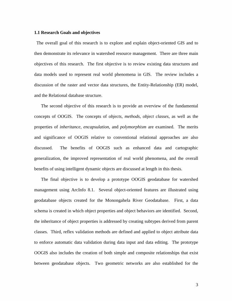
1.1 Research Goals and objectives
The overall goal of this research is to explore and explain object-oriented GIS and to
then demonstrate its relevance in watershed resource management. There are three main
objectives of this research. The first objective is to review existing data structures and
data models used to represent real world phenomena in GIS. The review includes a
discussion of the raster and vector data structures, the Entity-Relationship (ER) model,
and the Relational database structure.
The second objective of this research is to provide an overview of the fundamental
concepts of OOGIS. The concepts of objects, methods, object classes, as well as the
properties of inheritance, encapsulation, and polymorphism are examined. The merits
and significance of OOGIS relative to conventional relational approaches are also
discussed. The benefits of OOGIS such as enhanced data and cartographic
generalization, the improved representation of real world phenomena, and the overall
benefits of using intelligent dynamic objects are discussed at length in this thesis.
The final objective is to develop a prototype OOGIS geodatabase for watershed
management using ArcInfo 8.1. Several object-oriented features are illustrated using
geodatabase objects created for the Monongahela River Geodatabase. First, a data
schema is created in which object properties and object behaviors are identified. Second,
the inheritance of object properties is addressed by creating subtypes derived from parent
classes. Third, reflex validation methods are defined and applied to object attribute data
to enforce automatic data validation during data input and data editing. The prototype
OOGIS also includes the creation of both simple and composite relationships that exist
between geodatabase objects. Two geometric networks are also established for the

4
stream and road objects to demonstrate the object-based topologically integrated
geometric networks, and display methods are also defined to illustrate active feature-
linked annotation. Finally, the author undertakes a review and evaluation of OOGIS as
well as potential future directions of research in watershed resource applications.

5
CHAPTER 2: “Entity” Versus “Object” representation in GIS
There are three transformations that occur when modeling in a geographic
information system: external, conceptual, and logical transformations. Specifically,
external modeling provides the scientific basis for studying and understanding the real
world. At the conceptual level, organizing principles are established that transform the
external data model (scientific understanding) into functional descriptions and
representations of real world entities as well as define the relationships between and
among them (Hughes, 1991). Conceptual modeling involves the design of a schema that
is an abstraction of the real world situation under consideration (Hughes, 1991). A
conceptual model in a GIS may take the form of a vector, raster, or object representation.
A logical model is a computer model that constitutes a set of mathematical concepts used
to represent an explicit form of the conceptual model (Laurini and Thompson, 1993;
Worboys, 1995).
Data structures form the core of any conceptual spatial model and provide the
content information required to reconstruct the spatial data model into a digital form
(Carver et al., 1998). There are two primary data structures used in spatial data models:
the vector and the raster data structures. The vector data model captures real world
phenomena using Cartesian coordinates to represent spatial information from the spatial
primitives of points (nodes), lines (arcs), and areas (polygons). Vector models are often
used to represent features that are discrete in nature (Booth, 1999). Given a specific
reference scale for instance, an individual building may be represented as a point, a parcel
of land as a polygon, and a stream as a line feature.

6
A raster data structure utilizes an array of individual grid cells known as picture
elements or pixels. When modeling geographic phenomena in three dimensions using
the raster approach, an array of cubic cells known as voxels is used instead of pixels.
Pixels and voxels act as the building blocks for representing points, lines, polygons, and
surfaces. Raster data models are particularly useful in modeling continuous data such as
an elevation surface. The size of a pixel or voxel is important in a raster data structure
because each pixel is associated with a square parcel of land on the earth’s surface and
essentially determines the spatial resolution of the data (Carver et al., 1998: Burrough
and McDonnell, 1998). The raster and vector data structures form the building block for
the representation of entities in the entity-relationship model.
2.1 The Entity-Relationship Model
The most common conceptual model in current spatial information systems is the
Entity-Relationship (ER) model. The ER model represents the real world as a
combination of both the real world features or entities and the relationships that exist
between them. An entity can be a place, a thing, or a person. A land parcel, a landowner,
or fire hydrants are all examples of entities.
Chen (1976) first introduced the ER model in an attempt to identify all of the
important entities within a specific system and as a basis for defining the relationships
that exist between those entities. Essentially, the ER model is a means of organizing and
schematizing information at a conceptual level. The entities stored in the database are
represented in Figure 2.1 as boxes and linked by lines that represent the relationships
between the entities. In this example, the lines represent a many-to-one relationship

7
between “People” and a City” implying that many people live in one city. Note that M
signifies many entities and 1 signifies one entity.
Figure 2.1: An Entity Relationship Model indicating that many people live in one
city (Worboys, 1990)
The ER model recognizes the importance of aggregating entities with similar
properties into entity types. For instance, attributes can be assigned to entities such that
entities that share the same attributes can be aggregated into classes. It is also possible to
set the integrity constraints and cardinality constraints among entities in the ER model to
ensure that database integrity is maintained (Laurini and Thompson, 1994). In a land
ownership database for example, a cardinality constraint can be specified such that a
person can only own a maximum of two land parcels if that is a requirement of
landownership. The conceptualization of the ER Model is such that it provides a
representation of real world features based on entities and their relationships. Once the
ER model is determined, the logical implementation invariably takes the form of
representations encoded in a relational database structure.

8
2.1.1 Entity Representations in a Relational Database Structure
The relations among real world entities are represented as tables in a relational
model. The columns (fields) in a relational table usually contain attribute information
about the entities, whereas the rows (sometimes called records or tuples) contain
instances of an entity. One of the fields in a relational table must have a unique identifier
or key by which specific entities are identified. An identifier can be a social security
number, a geocode, or any arbitrarily assigned identifier (Laurini and Thompson, 1994;
Kemp and McDonnell, 1995). Relationships among entities are represented in a
relational database by linking the entities’ attribute tables with a common field from the
related tables.
While relational data structure is a sophisticated way of storing representations of
real world entities, some authors have identified several weaknesses (Laurini and
Thompson, 1994). The most common way of managing spatial data with the relational
technology is through a hybrid approach whereby the spatial data is separated from the
non-spatial data. The weakness of a hybrid approach is that the spatial data has a
“sheltered” existence outside the database thus making it cumbersome to apply the same
database integrity and security enforcements to both databases (Worboys, 1999). A much
better approach would be to integrate all the spatial and non-spatial data in the same
database and the object-oriented approach provides a suitable environment to address this
integration.
The relational database approach is efficient at describing one-to-one and one-to-
many relationships, but the many-to-many relations can be too complex to be handled in
the relational database. In the relational database approach, it is often necessary to create

9
additional tables to encompass all possible relationships, but this consequently poses
problems arising from data redundancy as well as data storage. Take for example the
entity relationship model of parcel ownership in Figure 2.2 in which one parcel owner,
Alan, owns one parcel of land. Such a simple one-to-one relationship requires the use of
three tables to represent the relationship between the entity “Owner” and the
corresponding entity “Land parcel (Figure 2.3). From Figure 2.3, it is evident that that
the representation of relationships in a relational database structure results in data
redundancy, which is a major problem in developing geographic information databases.
Figure 2.2: Entity Relational model of parcel-ownership: Alan owns land Parcel.

10
Owner-name Owner-ID Owner-Address
Alan 5667 6 Churchill Street
Ann 3445 1678 Peter Road
John 1888 3456 Chaucer Road
Parcel-ID Address
345 1st Street
346 1st Street
654 2nd Street
Owner-name Parcel-ID
Alan 654
Ann 143
John 487
Figure 2.3: Typical tables in a relational database (Laurini and Thompson, 1994).
OWNER
PARCEL
OWNER-PARCEL

11
Data redundancy is problematic because a query seeking one type of information in a
relational database may yield additional unnecessary information (Laurini and
Thompson, 1994). In the parcel-ownership example, if one requests the street address for
a specific land parcel, additional sensitive information linked to the requested parcel ID
such as the owner’s name and owner’s address is also released, thus posing problems of
privacy. Another major drawback of the relational approach is that information pertaining
to one entity is scattered throughout the database, making it cumbersome for a query
request to retrieve the requested information (Laurini and Thompson, 1994). The
limitation of the existing GIS database structures prompted scientists and software
developers to consider object-oriented technology as a way to improve spatial data
management and retrieval in GIS.
2.2 Object-Oriented GIS
2.2.1 Background
Object-oriented GIS has its roots in object-oriented computer programming
languages such as Smalltalk, C++, and Visual Basic. The history of object-oriented
languages dates back to the 1950s though the concept of an object was introduced by the
designers of a simulation language known as Simula-67. The idea behind Simula-67 was
that “objects have an existence of their own” and can be programmed to communicate
with each other during simulation (Abnous and Khoshafian, 1990:13). This
communication is possible because an object contains both data and methods that
determine the object’s behavior. Simula-67 also introduced the idea of object classes,
class inheritance, and class hierarchies that will be discussed later.

12
Another object-oriented programming language that became very influential
during the 1970s and 1980s was Smalltalk. Throughout the 1980s new programming
languages emerged as extensions, dialects, and versions of earlier prototypes. These
extensions included Objective-C and C++ from the original C language, and Object
Pascal, an object-oriented version of the computer programming language Pascal
(Abnous and Khoshafian, 1990). In the 1990s object-oriented languages became very
popular as application programmers realized the benefits provided by object-oriented
languages, techniques, databases, and user interfaces. Object-oriented approaches have
been promoted mostly in applications where the use of conventional modeling
technologies has been problematic (Worboys, 1995).
Several commercial GIS vendors have identified an object-oriented approach as
an appropriate way of modeling geographical phenomena. LaserScan Ltd. and GE
Smallworld Systems Ltd. have full-blown object-oriented applications encompassing
products that automate processes for designing physical facilities, managing operations,
and analyzing networks (GE Smallworld, 2000). Some spatial information systems that
incorporate object-orientation concepts include the LAMPS-2 system from LaserScan,
SMALLWORLD GIS from Smallworld Systems Ltd., and TIGRIS from Intergraph
Corporation. In 2000, Environmental Systems Research Institute Inc. (ESRI) upgraded
their ARC/INFO software to support object-oriented modeling. ESRI’s new ArcInfo 8.1
is a hybrid GIS that combines the benefits of the relational approach and those of object-
orientation to create an object-relational model.

13
2.2.2 Fundamental Concepts of Object-Orientation
Although object-orientation has been in existence for some time, there is
surprisingly neither a clear formal definition of the concepts behind it, nor a general
consensus as to what constitutes an object-oriented data model (Worboys, 1995). As
some have claimed (see Chance et al., 1999), the concept of object-orientation is not an
easy one to elucidate. Several authors have attempted to explain and define object-
orientation in similar, but yet different ways. Yourdon (1994:9) defines an object-
oriented system as “one whose components are encapsulated chunks of data and
functions which can inherit attributes and behavior from other such components, and
whose components communicate via messages with one another.” In object-oriented
systems, each real world entity is represented by an object to which is associated a state
and a behavior. The object state is represented by the values of the object’s attributes,
while the behavior is defined by the methods acting on the state upon invocation of
commands. Real world features are modeled as intelligent features that have not only
attributes, but also behaviors and relations with other objects. In this sense, an object is a
self-contained unit that is bound with behaviors that can be manipulated the user.

14
The major distinguishing features of object-orientation are comprised of several
elements. In an object-oriented model, an Object functions as a complex data structure
that stores all of its data along with information about the necessary procedures to create,
destroy, or manipulate itself (Hardy, 1999). Each object is identified using a unique
value known as an object identifier (OID) (Bertino and Martino, 1993:14). The unique
identifier enables an object to distinguish itself from other objects when such behavior is
specified. With object identity, objects can contain other objects and can refer to other
objects (Abnous and Abnous and Khoshafian, 1990).
Objects that share the same set of attributes and methods are often grouped
together into object classes. Each object has an object class to which it belongs. An
object instance contains the object’s graphical characteristics, its geographic location, and
all associated attributes. Composite objects are those that are logically composed of other
objects and whose operations propagate to the constituent objects. Very often the phrases
“composite object” and “object classes” are used interchangeably (Davis, 1994; Milne et
al., 1993).
Methods are rules that determine an objects’ behavior in OOGIS. The process of
associating an operation to a method is known as binding (Milne et al., 1993). Each
object class can have several methods and specific behaviors defined and can also inherit
methods from its parent class. When a method operating on an object is invoked by
sending a message to the object, the behavior bound to it is executed (Hardy, 1999).
There are several types of methods. Value methods return an answer to a message in the
form of attributes. Reflex methods are used to automate some operation such as data
15
validation. Display methods determine the appearance of an object when displayed at
different scales.
Encapsulation involves defining the internal implementation details of an object
and separating the code details from the external visible behavior (Bapat, 1994). Using
encapsulation, the object implementation details are screened out so that they are not
directly accessible to the end user. The external interface is in a way separated from its
internal subsystems, which are considered to be “irrelevant” to the end user. It is
important to note that encapsulation is not unique to object-oriented analysis. However,
when it is applied in tandem with method-binding, it provides the ability to define a clean
interface between an object’s internal and external aspects (Bapat, 1994).
Polymorphism is the ability of multiple objects to contextually “understand” and
interpret the same message. Polymorphism allows a message to be sent to different
objects such that each object can respond in a way appropriate to the kind of object it is
(Pinson and Wiener, 1988:17; Yourdon, 1994). As an example, if a message is invoked
to calculate the area of an object, different objects utilize different formulae for
calculating the area, depending on their shapes, but the common outcome will be the area
of each object. In this case, the message AREA would result in different methods of
calculating area:
Area (square)=length *width
Area (circle)=Pie*Radius*Radius
Inheritance is any mechanism that allows an object to incorporate all or part of
the definition of another object to form its own definition (Yourdon, 1994:7). If similar
objects share a subset of their properties, then their common properties can be abstracted
into a super class or a parent class. The object classes whose common properties have

16
been abstracted are known as sub-classes or subordinate classes. New relationships can
be established between objects by means of aggregation, generalization, specialization,
and association. Relationships and dependencies between and among objects can also be
defined for related objects. An example of inheritance is shown in Figure 2.5 whereby
CITY and VILLAGE inherit the same characteristics of having people, buildings, and
infrastructure inherited from the super class, SETTLEMENT.
Figure 2.4: An example of inheritance (Adams et al., 1996:651).
[The parent class is this example is Settlement, and the subclasses are City and Village.
City and Village have similar properties that characterize them as Settlement, but also
have particular properties that are specific to each subtype.]

17
Extensibility is a property that allows a user to define additional classes and sub-classes
to an existing object model. This incremental model and database development is made
possible through the properties of inheritance, encapsulation, and polymorphism (Laurini
and Thompson, 1993; Milne et al., 1993). Thus, new objects and relationships can be
added, removed, or modified to allow for the incremental development of a system.
Extensibility also enables the development of generic objects that can be inherited by
others and customized for specific applications.
2.3 The Significance of Object-Orientation in GIS
2.3.1 Enhanced Representation of Real World Features The OO approach provides a richer model for spatial data representation and
processing (He et al., 1999). In OOGIS, real world features are represented not only as
entities with spatial characteristics and attributes, but as objects that have additional
properties including intelligent behavior and relationships. The behavior of an object is
defined by methods that determine the operation and representation of the object
(Worboys, 1995). Through the encapsulation of data and behavior to objects the
abstraction of real world entities becomes more holistic and representative of real world
features (Adams et al., 1996:651). In OOGIS for example, a road is not just represented
as a linear feature made up of attributes and geometry, but rather as an object with
behaviors that better represent real world features. When editing a road object in OOGIS,
the system can be made to automatically generate an error message if the road is
accidentally assigned to a stream object class. Furthermore, the object’s behavior and
methods allow each road object to recognize which features the road object is related to,

18
which other features the road object is connected to, and what to do when the related
objects are manipulated. Thus, if a composite relationship method is defined for a road
object class and a traffic light object class, the removal of a specific road feature from the
database leads to an automatic deletion of the corresponding traffic light. However, the
removal of a traffic light object may not necessarily lead to the removal of the road object
because in the real world a road can exist without a traffic light.
In OOGIS, different generalization strategies such as aggregation, and association
make it possible to model hierarchical relationships among real world features (Adams et
al., 1996). All roads for example could be classified under one object class, Roads
because they have basic common characteristics. However, it is also possible to create
subclasses of roads that inherit the characteristics of transportation routes but are more
specialized and may comprise subtypes such as Interstates, County roads, State routes,
and so forth. OOGIS therefore provides the ability of a road object to “know” what
parent class it belongs to, what subtype it belongs to, and how it should behave when the
parent class is manipulated. This type of representation resembles the intuitive processes
that take place in the real world.
2.3.2 Data Integration and Cartographic Generalization
Brueger (1995) contends that integrating spatial data at different scales and
formats is often problematic in conventional GIS because of the use of “inappropriate
conceptual models.” The entity-relational model used in current spatial information
systems does not provide a means to effectively facilitate the integration of raster and
vector properties since entities are modeled as either raster or vector types. As a result, it
is often necessary to either move across different software platforms or utilize software

19
extensions to analyze information of each type. LaserScan (n.d.) argue that OOGIS
provides an approach that will solve the integration problem of combining raster and
vector data types.
Data integration is more effective in OOGIS because an object can be defined to
be either a raster or a vector if such behavior is specified. In OOGIS, an object may be
defined to have either or both vector and raster characteristics, thereby solving the
significant problem of raster-vector repsresentation (LaserScan, n.d.). The object
hierarchy approach can be used to relate multi-scale data as well as integrate and merge
objects at different scales (He et al., 1999). Moreover, the object approach makes it
possible to integrate small-scale data and large-scale data by adding only the shapes of
those entities that appear at that particular scale. He et al. (1999) identify three important
points to consider in performing data generalization. First, the elimination of redundant
features during data generalizations should not compromise the topological relationships
among features (Figure 2.6 a). Second, when eliminating features, some topological
relationships within composite features may be changed, but the relations between
composite features must be maintained (Figure 2.6 b). In this case, the topological
relationships between the composite features will be visible, but sub-features within a
composite entity will not. Third, the shapes of features may change when displayed at a
smaller scale such that the real shape of one feature can only be seen at one particular
scale (Figure 2.6 c). In this case, the shapes of the features may be changed but their
topological relations will remain the same (He et al., 1999).

20
Figure 2.5: Three cases of data generalization (from He et al., 1999)
a) Elimination of some features
b) Simplification of features
c) The shape of entities changed

21
Often in GIS, it is necessary to integrate data of different scales for specific
purposes. The U.S. Environmental Protection Agency (EPA) for example is developing a
National Water Quality Standards Database that will enable EPA, States, Tribes, and the
public to view designated uses and criteria for the surface waters of the United States on
the Internet. This initiative is an ongoing effort that requires the conflation of large-scale,
high-resolution water quality datasets (1:24000 scale) from State governments to the
EPA’s National Hydrography Dataset (1:100000) that contains stream hydrography and
river reach information (Bryan et al., 2001). Using the entity-relational approach,
integrating data at multiple scales is a time-consuming task that requires georeferencing
maps of entities from one reference scale to another. As a result, several institutions
including the EPA have adopted new approaches such as OOGIS in order to more
efficiently conflate multi-scale datasets. Using OOGIS, it is possible to define multiple
representations of data that are appropriate to the level of display and the generalization
of the feature’s geometry.
In OOGIS, features are modeled as objects that have generalization behaviors
specified by methods in the database schema. A scale-dependent display of geographic
data is possible in OOGIS through the use of methods that define the alternative scales
that apply to an object (Laser-Scan, n.d.). In defining object properties, it is also possible
to specify commands for special display and graphic attribute loading for enhanced
cartographic generalization (Davis, 1994). Methods can also be established such that
when data is to be displayed at a different scale, the features and graphics appear at an
appropriate resolution. Messages can also be sent to selected objects to invoke the
process of generalization. The behaviors attached to objects allow the objects to

22
automatically determine what to do when a generalization message is received.
Significantly, since a hierarchy of relations can link the objects, the generalization
message can be propagated to other objects. Because of polymorphism, the multiple
geometries that are assigned to an object can be used to determine how an object should
be displayed at different scales (Davis, 1994). As discussed earlier, polymorphism
allows object classes to respond to the same message different ways. In a nutshell, the
object-oriented approach to GIS makes the multiple-representation of data, and the use of
multi-scale data a much feasible option especially in Internet mapping.
2.3.3 GIS Database Update
A further major weakness of conventional relational data structures identified by
Batty and Newell (1994) is the poor handling of long transactions and version
management. A long transaction involves updating data over a long period of time. This
is distinct from short transactions such as when a banking system transfers money from a
checking account to a saving account whereby the update is reflected instantly. A short
transaction takes just a fraction of a second (Newell, n.d.). However, GIS updates can
involve both short transactions and long transactions. Examples of a short transaction in
GIS would be vehicle tracking, fault-logging, or emergency planning (Newell, n.d.).
Long transactions are those that take place over a long period of time, and often require a
period of up to several days, weeks or even months to complete. Typical long
transactions in a GIS include data input, data conversion, and geo-referencing. A
significant amount of time is often required to edit a GIS database or input additional data
into a database, to edit the data by converting it from one data type to another, and
perhaps to georeference a dataset.

23
The most common solution to handling long transactions in prevailing GIS
databases is through a method known as checkout. Checkout involves selecting and
copying the data from the database relating to the user's area of interest, so that the data is
only available to that single user. The necessary updates can be made to the selected
dataset and eventually recombined with the master database (Batty and Newell, 1994).
Checkout is problematic because it limits the user to a subset of the database (Batty and
Newell, 1994). Problems also arise with the checkout approach when the data copied for
update is topologically linked to data that was not selected from the master database. If
the user needs to use data not previously selected, then the process of copying a subset of
the data must be repeated, resulting in an even longer transaction period.
A powerful approach to handling database updates without the problems
encountered in the checkout approach is provided by OOGIS in the form of version
management or versioning. Version management is the simultaneous existence of several
versions of the whole database. In a versioned database, users have their own versions of
the entire database, such that at the end of the transaction, the updated versions are
combined with the master database (Worboys, 1995). Versioning is more efficient for
long transactions because all the necessary data is made available to the user who has
access to the entire version of a database for the duration of the transaction. It is
important to note that versioning and support for long transactions are not exclusive to
object-oriented GIS. However, object-orientation provides a very effective framework for
implementing versioning through the use of version merging (LaserScan, n.d.). Version

24
merging occurs when changes to one data version are merged into the master database
after a long transaction. When objects are created in OOGIS, their properties are defined
so that each object has a specific identifier and specific attributes that are used by the
objects for self-assessment to determine whether the objects in the database belong to the
right object class or subclass. During version merging in OOGIS data validation reflex
methods defined for objects in a database automatically resolve conflicts that arise
between updated objects and specific object classes (LaserScan, n.d).

25
CHAPTER 3: Watershed Resource Management
Watersheds are emerging as the key biophysical unit within which management
regimes operate. A watershed or catchment area is a “geographic area in which water,
sediments, and dissolved materials drain into a common outlet or a series of ecosystems
that are spatially and temporally linked by the downward flow of water” (Fulcher et al,
1997:1). A watershed divides and separates one drainage basin from another. The
drainage system within a watershed may consist of a surface stream or a body of
impounded surface water together with all tributary surface streams and other surface
water bodies (Iseri and Langbein, 1995).
There is a growing consensus that studying water resources at a watershed level is
necessary for acquiring information on factors influencing water quality. This regional
scale of analysis is referred to as the Watershed Protection Approach (WPA).
Specifically, the WPA involves the overall inclusion of environmental factors that may
impact public health, drinking water quality, and biodiversity. The WPA is tied to
initiatives that encourage states to implement programs that manage watersheds for the
protection of aquatic systems, water quality, and human health (United States
Environmental Protection Agency, 1999). States are required by the United States
Environmental Protection Agency (USEPA) to implement programs that are tailored to
the state’s local conditions (United States Environmental Protection Agency, 1999). In
West Virginia, for example, environmental issues arising from coal mining activities are
emphasized and prioritized in watershed management strategies.
Watershed protection is emphasized because of the benefits to communities and
the health of the ecosystem within it. For this reason, a regional focus is deemed more

26
beneficial for managing water resources because it provides a holistic understanding of
the overall conditions within a watershed system. Although an effluent-emitting point
source of pollution such as a factory is important in influencing water quality, it is also
important to consider the overall contribution of other activities within the watershed
such as non point-source runoff from agricultural lands and from mining activities. The
United States Environmental Protection Agency (2001) recognizes that an equitable
allocation and coordination of National Pollutant Discharge Elimination System
(NPDES) permits is also more effective if managed at a watershed scale. NPDES
permits are standards set by the USEPA to limit the amount of pollutants that can be
discharged into the water. Thus, rather than focusing on a single specific problem
pertaining to only part of the watershed system, the watershed approach provides a
regional approach that uncovers the many interrelated “stressors that affect a watershed
system” (United States Environmental Protection Agency, 1996). In addition to pollution
control, biologists have also adopted the watershed regional focus level as a rational way
to address biodiversity (Chattooga River Watershed Council, 1996).
The significance of the landscape approach arises from the fact that the
disturbance of one entity in an ecosystem often results in the disruption of the entire
ecological network. For example, if a river is heavily polluted by pesticides or factory
discharge, then aquatic life is directly affected. The disturbance of the ecological
network poses a chain of problems that include the disruption of organisms’ natural food
chain. The mapping of the watershed and ecological interrelations at a regional scale
promises to be a fertile area for testing and exploring the potential of OOGIS.

27
3.1 GIS in Watershed Management
Recent literature on watershed studies indicates a considerate interest in
watershed analysis using “conventional” GIS (Claggett et al., 1995). Researchers from
different fields including hydrogeology, environmental economics, land-use planning,
and environmental protection have all investigated watershed based environmental
management using GIS. The Boise Cascade watershed analysis program, for example, is
an initiative by Washington State to study natural processes and historical land
management as they affect stream conditions in the Boise Cascade region (Wold, 1996).
In the Boise Cascade project, specialists from diverse disciplines such as forestry,
geology, soil science, and geomorphology collaborated to inventory the conditions of the
Boise watershed. Following the inventory, natural resource sensitivities and
vulnerabilities are identified as well as the existing and potential public impacts on the
watershed system. Wold (1996) recognized GIS as an important framework for
measuring a watershed’s natural resource parameters, but he nonetheless warned about
many different GIS systems that would need to be evaluated to meet a user’s specific
needs.
In a similar study, the Canaan Valley Institute (CVI) conducted a study to assess
the cumulative environmental impacts of mountaintop removal in the Central
Appalachians (Claggett et al., 1995). The CVI methodology included the use of GIS data
and the National Land Cover Dataset to identify landscape indicators of environmental
deterioration. Some of these landscape indicators assessed the impact arising from
streams passing through mined area relative to non-mined areas such as a forest. The
results of this study indicate that the latter received far fewer pollutants than the former

28
because the natural forest environment slows runoff and filters out some nutrients before
the water reaches a stream (Claggett et al., 1995). Others (Lovejoy, 1997) proposed the
coupling of GIS with simulation models to predict pollution sources and determine the
impact of land use change on water quality.
In another research project, the Montana Department of Environmental Quality
(DEQ) is developing an integrated database for their state based on water, air, waste
management, and energy parameters as a step towards protecting Montana's
environmental resources. The DEQ used ArcView GIS to create a spatial database for
monitoring ambient water quality, identifying impaired water bodies, and facilitating
water quality database maintenance. The product known as MontanaView is used for
multiple tasks such as NPDES permitting; developing a comprehensive list of water
bodies in need of water quality restoration; conducting a historical review of impaired
waters; and incorporating land use information to help identify potential pollution sources
(Field et al., 2000).
Over the years, numerous hydrological models have also been developed and
integrated with GIS, to study hydrological operations at a watershed scale. Some of these
include the Watershed Management Decision Support System (WAMADSS), the Ground
Water Loading Effects of Agricultural Management Systems (GLEAMS), and the Spatial
Water Budget model. ESRI’s ArcView Spatial Analyst also supports hydrologic
operations such as watershed delineation, as well as providing for the calculation of flow
directions and flow accumulations.
More recently there has also been interest in the application of object-oriented
GIS to water resource management. Cai, et al. (1997) developed a prototype GIS-based

29
spatial decision support system (SDSS) that integrates social, economic, and
environmental factors related to a river system. The close coupling of a SDSS and the
visual and analytical advantages of GIS provides a powerful automated and interactive
approach to hydrological decision-making. Water utilities industries have especially
benefited from OOGIS. The Greenwood Commissioners of Public Works (CPW) in
Greenwood, South Carolina used LaserScan’s OOGIS GOTHIC software for utility
management. OOGIS is beneficial to the utility industry for several reasons. Through
the process for binding specific behaviors to specific objects, OOGIS provides the ability
to define specific connectivity rules of utility pipelines, components, and the automation
of data validation rules (Hartnall and MacAlister, 1998).
A recent breakthrough in the use of OOGIS for watershed management has been
the emergence of the ArcGIS Hydro data model. The ArcGIS Hydro data model is an
object-oriented model for river, watershed, and other surface water hydrology
applications. At the time of writing, the ArcGIS Hydro data model was still under
development by ESRI and the Center for Research in Water Resources (CRWR) located
at the University of Texas at Austin. The ArcGIS Hydro data model incorporates both
the hydrography and the hydrological properties of water features and represents
hydrological features in a GIS, facilitates the creation of spatial data for hydrologic and
hydraulic models, and automates spatial data manipulation (Figure 3.1) (Davis and
Maidment, 2000).

30
Figure 3.1: The ArcGIS Hydro Data Model (ESRI and the Center for Research in Water Resources (CRWR), The
University of Texas, 2001)

31
The ArcGIS Hydro data model captures the essential generic concepts of a
hydrologic model, and can be customized for specific hydrological applications to suit a
user’s needs. The ArcHydro data model is being implemented in several applications
including a Watershed Atlas for the British Columbia Ministry of Environment, Lands
and Parks; a Hydrologic Modeling System by US Army Corps of Engineers Hydrologic
Engineering Center; and in a software package for river and floodplain modeling by the
Danish Hydraulic Institute (Davis and Maidment, 2000). The National Hydrography
Dataset (NHD) is also a product of the ArcGIS Hydro data model. The NHD is a
comprehensive spatial dataset containing information about surface water features such
as lakes, ponds, streams, rivers, springs and wells derived from the USGS Digital Line
Graph hydrography (DLG) as well as from reach-related information from the EPA
Reach File Version 3 (REACH3) (United States Geological Survey, 2001). The lines
representing streams in the NHD dataset contain dynamic stream properties such as the
direction of water flow and the flow change over time (United States Geological Survey,
2001; Maidment, 2000).

32
CHAPTER 4: OOGIS-The ArcInfo Method
4.1 Review of OOGIS in ArcInfo 8.1
Before the implementation of an object-oriented approach in ArcInfo 8.x, ESRI’s
software was entirely based on a geo-relational database model known as the coverage
data model. ArcInfo was launched in 1981 as a command line-driven program operating
under the Microsoft Disk Operating System (MSDOS). The coverage data model is
limited in its representation of real world entities because all features are aggregated into
the basic entities of points, lines, and polygons (Zeiler, 1999). Limitations of the
coverage data model demanded the tight coupling of spatial features with their respective
behaviors.
Significantly, ArcInfo 8.x software supports both the geo-relational and object-
oriented data models and in a way, the coverage geo-relational model has been
augmented to include an object-relational database model known as a Geodatabase. The
object-oriented data model enables a user to access the full benefits of OOGIS by
embedding methods, behavior, and hierarchical relations into the geographic feature or
object (Booth, 1999). ArcInfo 8.1 has a user interface and embedded wizards that
facilitate interaction between the user and the system. The environment in ArcInfo8.1
makes it possible for both programmers and non-programmers to build intelligent
databases using visual and menu-driven tools (Booth, 1999).
The generic object-oriented model in ArcInfo 8.1 supports a programmable
environment that enables the software to be tailored to meet different application needs.
Furthermore, the new software environment supports Component Object Model (COM)

33
programming languages such as Visual C++ and Visual Basic that enable the user to both
extend the software functionality and customize the application (Booth, 1999).
ArcInfo 8.1 is composed of three major applications: ArcMap, ArcCatalog, and
ArcToolbox. ArcMap has a user interface similar to the one in ArcView GIS, but retains
the full functionality of ArcInfo (Booth, 1999). ArcMap has functions for display, query,
and spatial analysis. ArcMap also incorporates an Object Editor for creating and editing
features, defining object behaviors, versioning, advanced customization, and also
provides for conflict resolution of changes made to a database when merging different
versions into a geodatabase. Figure 4.1 shows a typical ArcMap graphic user interface
(GUI).

34
Figure 4.1: The ArcMap Graphical User Interface

35
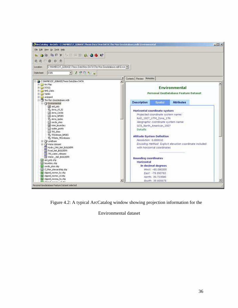
ArcCatalog provides new functionality in ArcInfo that supports the browsing and
management of spatial data (Figure 4.2). Data browsing in ArcCatalog includes the
ability to connect to folders, databases or even Arc IMS Internet servers like the
Geography Network to retrieve data for input into a GIS. Data management involves
refining data and binding it with validation methods, inheritance properties, and
relationship rules. ArcCatalog also allows a user to create new shapefiles, associated
database tables, and INFO tables for ArcInfo coverages. It is also possible to generate
metadata using the available metadata style-sheets in ArcCatalog and the ability to
preview those geographical data, associated tables, and metadata.
36
Figure 4.2: A typical ArcCatalog window showing projection information for the
Environmental dataset

37
The third major application available in ArcInfo 8.1 is ArcToolbox. ArcToolbox
is used for geoprocessing operations such as overlay, buffering, and many other map
transformations. In ArcTolbox, there is a Geoprocessing Server that allows for
geoprocessing operations on a client desktop and for subsequent submission to a server
for execution and processing (Viennaeau, 1999). ArcToolbox has menu-driven tools and
wizards that support direct interaction with the user. Figure 4.3 is an ArcToolbox
window showing some of the possible applications and tools.
Figure 4.3: Geoprocessing options in Arc Toolbox

38
4.2 Geodatabase Design
A geodatabase is an object-relational database that has a collection of datasets,
spatial and non-spatial object classes, and relationship classes (Zeiler, 1999). A
geodatabase stores data and information that describe geospatial objects in a relational
database format (Maidment, 2000). Geodatabases are classified into two types depending
on their size and accessibility: Personal Geodatabases and ArcSDE Geodatabases.
Personal geodatabases represent small to medium datasets and are limited to one or a few
users, whereas ArcSDE databases represent large, multi-user datasets.
The process of designing a geodatabase involves two critical stages: the logical
and the physical design. The logical data model is the initial phase in the design of a
geodatabase. The key issue in the implementation of the logical phase is to identify
organizational functions that represent the needs of potential users of the database. The
logical design is achieved by defining the object properties and object relations that need
to be included in the database. Several issues must be addressed when implementing the
logical design. Some of the issues addressed at the logical phase include determining the
type of data to be incorporated in the database; the geographic location and projection of
the data; the relevance of subtypes or subclasses in the dataset; the presence of geometric
networks; and other general relationships. Once data issues and object properties are
addressed, the physical implementation of the database can proceed.
In the physical implementation stage, object classes and their relationships are
identified, and attribute types and domains are defined for specific objects. Furthermore,
object validation methods and relationship rules are defined in the data model. Object

39
rules include validation rules, relationship rules, and connectivity rules. The
implementation phase also includes the definition of methods that determine the behavior
of objects when they are separated or combined (Zeiler, 1999).

40
CHAPTER 5: An Object-Oriented GIS of the Monongahela River Watershed
5.1 Study Area: The Monongahela River Watershed
The Monongahela River originates at the confluence of the West Fork River and
the Tygart Valley River in West Virginia. The Monongahela River flows northwards
towards Pittsburgh, Pennsylvania. The case study focus of this research is based on the
sub-watershed of the Monongahela River in Monongalia County, West Virginia (Figure
5.1). The study region covers an approximate area of 15.4 square kilometers.

41
Figure 5.1: Map of the Study Area

42
5.2 Data
The primary data for the watershed case study was obtained from the West Virginia
Department of Environmental Protection, the West Virginia GIS Technical Center, and
the Environmental Protection Agency. The geographic projection used is Universal
Transverse Mercator-zone 17, North American Datum 1983. The data components
include watershed boundaries, hydrography, transportation, abandoned mine lands,
Superfund sites, Toxic Release Inventory, National Hydrological Dataset, National
Pollutant Discharge Elimination System (NPDES) outlets, land stewardship, and
wetlands. Table 5.1 shows the different types of data used to create the watershed
geodatabase.

43
Table 5.1: Data used in the case study
Feature
Scale
Symbology
Description
Sub-watershed
(HUC: 05020003)
1:24000 Line Catchment basins delineated using a Digital Elevation Model
Hydrography 1:24000 Line Vector representations of streams, rivers, lakes, ponds, dams, marshes, and
other detailed hydrographic features
National Hydrography Dataset 1:100000 Line Database containing the USGS DLG hydrography and reach-related
information from the EPA Reach File Version 3 (RF3)
Roads 1:24000 Line A vector representation of roads, trails, and other transportation features from
USGS
Abandoned Mine Lands (AML) 1:24000 Polygon
Line
Point
Extent of the mining permit areas and locations.
Comprehensive Environmental Response,
Compensation, and Liability Information
System (CERCLIS) Sites
1:24000 Point USEPA Superfund Contamination Sites: includes abandoned warehouses,
manufacturing facilities, processing plants, and landfills
Toxics Release Inventory Sites 1:24000 Point Location of the facility where chemicals are manufactured, processed, or
otherwise used
TRI Database Database table Detailed database information about toxic chemicals that are used or produced
by industries and discharged into rivers, lakes, streams, and other water bodies
National Pollutant Discharge Elimination
System (NPDES) outlets
1:24000 Point Mining-related NPDES outlets
Land stewardship 1:24000 Polygon Land ownership and management information from the National Gap Analysis
program.
Geographic Names Information System 1:24000 Point An automated inventory of the names and locations of physical and cultural
geographic features

44
A watershed is a complex entity that poses several challenges when represented in
a spatial information system. A watershed is composed of lakes, rivers, streams, roads,
and other man-made features and locations. Furthermore, there are different networks,
associations, and processes occurring in the hydrological system that need not be
overlooked when designing and implementing a GIS database. This section seeks to
explore the use of OOGIS to establish a geodatabase that will use simple objects where
possible, to represent the watershed system and define the interaction between individual
watershed features. The object-oriented approach is utilized because it supports a high
level of data representation through the integration of intelligent behaviors, reflex
methods, and connectivity rules. The object-oriented approach also intuitively represents
the complexity of the watershed. The following discussion elaborates on some of the
object-oriented features of the Monongahela Geodatabase and presents a prototype
OOGIS for watershed resource management. The Monongahela Geodatabase properties
include the schema design, data integration, object inheritance, data validation methods,
relationships, display methods, and object-based networks.
5.3 Schema
The properties of the data used in the Monongahela Geodatabase were defined in
what is known as a database schema. The schema contains details of a set of objects as
well as information that describes the properties of the data. A schema specifically
contains information such as the type of data, the relationships among data, and the
hierarchy of related objects within the geodatabase. There are two key ways to create a
schema in Arc Info 8.1. The first option allows the user to utilize the tools available in

45
ArcCatalog to create a database schema and then import the relevant data into a
geodatabase. The second method involves the creation of more advanced objects using
Computer Aided Software Engineering (CASE) tools. In the latter approach, the object
data model is designed using Unified Modeling Language (UML) diagrams. The
resulting UML diagram is subsequently exported into the Microsoft repository, and then
into ArcCatalog to create a schema.
This study utilized the first option. A schema was created in Arc Catalog based
on the watershed data. The data was initially aggregated into three major thematic
categories to form the Landbase, Water, and Environmental feature1 datasets. The data
was then loaded into their respective feature datasets using the import tools in
ArcCatalog. Figure 5.2 shows how shapefiles were imported into the geodatabase and
Figure 5.3 shows the data structure of the Monongahela River Watershed Geodatabase
(The Mon Geodatabase). The data that did not correspond to the Landbase, Water, and
Environmental feature datasets were loaded as standalone feature classes. The full
database schema for the Monongahela geodatabase is presented in Appendix A, and the
details of the data properties are discussed in the rest of this chapter.
1 The words “feature” and “object” are used interchangeably hereinafter

46
Figure 5.2: Using ArcCatalog to import a shapefile into a geodatabase

47
Figure 5.3: The Monongahela Geodatabase showing the datasets and object classes

48
5.4 Data Integration
In OOGIS, the spatial and non-spatial information is integrated into the same
geodatabase so that the intensity constraints can be simultaneously applied to both spatial
and non-spatial data. Similarly, the geodatabase model provides an effective way to
integrate spatial data of different formats and different scales. Using the geodatabase
model it is possible to import different data formats such as ArcInfo coverages, ArcView
shapefiles, and geoobjects. Although most of the data for the case study is in shapefile
format, it is also possible to integrate other data formats as well. ArcInfo 8.1 also
provides the ability to integrate multiple scale data into the geodatabase as long as the
reference scale is specified for the feature dataset in which the data is to be imported.
The ability of OOGIS to support multi-scale data was tested in the case study by
integrating two hydrography datasets at two different scales. The WVDEP wetlands data
is available at a scale of 1:24000, and the NHD dataset is at a scale of 1:100000 (Figure
5.4). Traditionally the integration of multi-scale data and conflation is a difficult task in
GIS. In the Monongahela Geodatabase, the reference scale for the Water feature dataset
was specified as 1:24000 and was defined to automatically georectify other scales to the
reference scale. As a result, the multi-scale integration becomes automated, allowing the
user to directly overlay the two data layers for analytical purposes.

49
Figure 5.4: An overlay of multiple scale data: 1:100000 NHD dataset and 1:24000
wetlands. [Notice that in the NHD hydrography (blue lines), the 1:100000-scale data is
more generalized. However, the 1:24000 enables more detail and small features such as
ponds that are not visible at the 1:100000-scale to be displayed].

50
There are several benefits to data integration provided by the object-oriented
geodatabase model in ArcInfo 8.1. First, the geodatabase is an integrated database that
allows the management of spatial and non-spatial data in the same database. The benefit
of the integrated approach is that the information on topology and other non-spatial
attribute data is not isolated, and can thus be manipulated together without having to
work on one dataset and then join the different tables thereafter. Furthermore, the
integrity constrains specified for the geodatabase enforce concurrency on both spatial and
non-spatial data. A further benefit of the geodatabase model is that it allows the
integration of geoobjects, coverages and shapefiles, thereby reducing the problems of
shifting between different software interfaces and minimizing any additional
programming required to switch between the different file formats. Another benefit
relates to the integration of multi-scale data. In the geodatabase approach, it is possible
to automate the multiscale scale data integration, whereas in the “conventional” geo-
relational approach, it would take a series of operations and a considerable amount of
time to georectify the two datasets before they could be overlaid.
5.5 Object Inheritance
Features in a watershed have both generic and specific characteristics. For example, all
the hydrological entities in a watershed can be classified under one umbrella as water
features. At the same time, it is also possible to identify each hydrological feature as a
specific element with specific characteristics. A pond, for example is a water feature, but
it is also a different feature from a stream, even though they share the same basic
characteristics.

51
In a geodatabase, objects can be stored as either spatial objects in feature classes
or as non-spatial objects in tables. Tables and feature classes store objects that possess
the same behavior and attributes or that are of the same type. Objects can be organized
into subtypes and can have validation rules attached to them. This hierarchical
inheritance of specific characteristics from generic watershed objects is achieved by
using subclasses or subtypes. Using the property of inheritance, an object class can be
further classified into sub-classes according to an object’s attributes and behavior.
In the Monongahela Geodatabase, object inheritance is demonstrated by creating
subtypes of the hydrological (HYDRO) and road (ROAD_24k) object classes. The
USGS attribute coding system was adopted to guide the creation of these subtypes. In the
USGS coding system, codes are used to identify different categories of information to
which a feature belongs. The USGS coding system was adopted in this object-oriented
environment to represent features with specific attributes and to create a hierarchy of
relationships between objects and object classes that can be subsequently modeled in the
OOGIS and represented on a map.
ArcCatalog was used to create subtypes from the “roads” and “hydro” parent
classes and the feature class properties dialog box (Figure 5.5) was used to create and
modify the subtypes. All hydrological features were grouped into one feature class called
HYDRO using the USGS General code 50, and defined as the parent class for
hydrological features and Code 50 was then set as the default value for any type of
hydrological feature. The HYDRO feature class was subsequently subdivided into more
specific subclasses such as Perennial, Intermittent, Ponds, and River Bank. Code 412
was used to create the subtype Perennial streams, Codes 412 and 610 for Intermittent

52
streams, Code 200 for Ponds, Code 605 for the right riverbank (RightBank), and Code
606 for the left riverbank (LeftBank). Figure 5.6 shows object inheritance as derived
from the HYDRO object class.
Figure 5.5: Creating HYDRO subtypes in ArcCatalog
[The subtype field is the field from which the parent class is identified. The subtype is
defined using the subtype Code and the Description. The specific attributes for each
subtype are then defined in the Domain and Default Value fields]

53
Figure 5.6: Subtypes of the Object Class HYDRO
[Codes 50=parent class representing any hydrological feature, code 412 is a perennial
stream code, codes 412 and 610 together specifically represent an intermittent stream,
code 200 represent ponds or shoreline features, code 606 represent the right riverbank,
and code 605 the left river bank]
Object Class

54
A second instance of object inheritance was constructed from the roads object class
(ROAD_24k). Just like the case of hydrological features, the general USGS code for any
type of road is 170, and this was applied as the parent class for all roads. The ROAD_24k
parent class (170) was subsequently subdivided into six subtypes. The road subtypes
include Primary roads (Code 201), Secondary roads (Code 205), Class 3 roads (Code
209), Class 4 roads (Code 210), Rail trails (Code 211), and Jeep trails (Code 212).
Figure 5.23 illustrates the subclasses inherited from the object class ROAD_24K.
Figure 5.7: Inheritance of ROAD_24K subtypes.
[The numbers represent the codes used to create subtypes. Primary roads (Code 201),
Secondary roads (Code 205), Class 3 roads (Code 209), Class 4 roads (Code 210), Rail
trails (Code 211), and Jeep trails (Code 212).]

55
After the subtypes were defined in ArcCatalog, the layers were exported to ArcMap to
associate the subtypes with the map features. This was achieved by setting ArcMap into
the editing mode, selecting the features to be subtyped, and then assigning subtypes to
each feature as shown in Figure 5.8.
Figure 5.8: Associating subtypes with features in ArcMap

56
One significant benefit of inheritance is that the data in the information system is
structured in a manner that is consistent with the watershed system being represented, and
also with the conceptual model detailed in the schema. In a watershed system the
hydrological system is composed of different specific features like ponds, streams and so
forth. A more intuitive abstraction of a watershed system should include the
representation of the generic classes that exist between database objects as well as the
specific sub-classes to which each object belongs. As a result, when manipulated, the
object performs a self-validation check to ensure that the object is valid and belongs to
the right object class. Furthermore, the inheritance capability enables the user to annotate
the resulting object classes according to their subtypes. For example, instead or having a
homogeneous representation for all hydrographic features, the features are represented
according to what subclass they belong, thus making visual interpretation more
meaningful. Figure 5.9a is the map of features before subtyping was performed and
Figure 5.9b is the map of features with the subtypes. It is important to note that although
the class-specific annotation capability is not unique to OOGIS, the ability to define class
hierarchies and self-validation methods in an object-oriented environment makes it more
effective to edit features in a geodatabase.

57
Figure 5.9a: Map of General Hydrological Features before subtyping.
[The entities on this map are represented with homogeneous lines that do not reflect the specific hydrological features represented.]

58
Figure 5.9b: Map of subtypes created from the Hydrological object class, HYDRO.
[Polymorphism: hydrographic features are represented using different linear symbols that
resemble the subtypes of HYDRO.]

59
5.6 Data Validation Reflex Methods
Managing an information system for watershed resources involves the compilation
of datasets such as land stewardship information, pollution point source locations, and
hydrography, which are obtained from a variety of sources. All these different sources of
data have different standards of accuracy that might need to be reassessed to meet the
standards of the watershed information system. In this respect, it is valuable to
incorporate data validation procedures at the database level that would then enforce the
accuracy requirements consistent with watershed management standards. In OOGIS, the
data validation process can be achieved through the application of default values,
attribute domains, and split or merge rules operating on objects and object classes.
The use of default values and attribute domains makes it possible to maintain valid
attribute values for watershed geodatabase objects. Zeiler (1999) defines attribute
domains as constraints on attributes that define the valid entities for a particular subtype
or feature class (Zeiler, 1999). There are two types of attribute domains: domain ranges
and coded domains. Domain ranges are a subset of numbers that constrain data values to
a specified minimum and maximum range. Coded values are discrete descriptive
attributes that are assigned to specific objects in a geodatabase. In section 5.3 subtypes
were created using the USGS coding system. In this section, attribute domains were used
to enforce data validation by constraining database elements such that only specific
values could be assigned to specific object classes and subtypes. For example, all
hydrological features only took the descriptive value of 50 whereas perennial streams
were specifically assigned the value of 412. As a result, if any other attribute value is
entered into the constrained database fields, an error message will be generated.

60
Once attribute domains are defined for objects in the database, it is possible to
check which objects conform to the specified rules and attribute domains. The validation
check is illustrated in Figure 5.10 using road objects to verify if all the road subtypes
have valid values. To perform a validation procedure, the features to be validated are
selected, and the validation option from the Editor Menu (Figure 5.10). If features in the
database are invalid, an error message and flag will appear specifying the number of
invalid objects. The invalid objects then remain selected so that they can be corrected. In
this project, the validation approach was used to verify the validity of road subtypes.
Figure 5.11 shows the validation output with the invalid features highlighted. Note that a
message also appears after the validation procedure is completed, informing the user
about the number of invalid features.
Figure 5.10: Validation in Arc Map

61
Figure 5.11: Arc Map Window showing the number of validation features. The
selected features in blue are the invalid features.

62
After setting the attribute domains, split and merge policies were also defined to specify
the behavior of the features when they are separated or combined. When features are
split, they may take a specific default value or take a duplicate value of the original value.
Similarly, when features are merged the resulting feature may take a duplicate or a ratio
of the original objects’ attributes. In this study, the split rules were specified such that
new objects inherit the attributes of the original class by default and when merged.
Default values were also defined for all subtypes such that when new features are added
to a subtype, the attributes for that specific attribute are automatically attached to the new
features. When default values are defined, the new feature added to an object class or to
a subtype in ArcMap will automatically inherit the default values initially specified for
that feature class or subtype. For example, the road (ROAD_24k) feature class was
selected for editing, specifying the Class2 road as the edit subtype as shown in Figure
5.12a. In this case, an additional road feature is added to the road object class by initially
selecting the target subtype (Secondary Class 2 in the Target pull-down menu of Figure
5.12a), and the new feature drawn. When the new road object was added, the default
value for a Secondary Class2 attribute was automatically added to the new road feature as
shown in the attribute box in Figure 5.12b. The ROAD_24k in Figure 5.12b is the feature
class for roads and the plus sign (+) next to the object ID indicates that the road class has
subtypes.

63
Figure 5.12a: Setting a subtype field for editing

64
Figure 5.12b: Values for new subtype objects automatically added to new features

65
A significant benefit of OOGIS is the ability to create intelligent objects and specify
validation rules that are automatically implemented to enhance data validation procedures
and aid in the maintenance of the GIS database. GIS maintenance is one aspect of GIS
implementation that has often come as an afterthought rather than as part of the planning
and development of the information system. Imwalle (1996) suggests that a logical
approach to GIS maintenance must be addressed early in the GIS implementation plan,
particularly during the database design process. Furthermore, a significant number of
communities and non-profit organizations utilize watershed information systems to attain
a sustainable use of watershed resources. For some watershed managers whose specialty
is not information science, it is necessary to address GIS maintenance and accuracy
issues at the database level. The OO approach provides a cost-effective way to address
data maintenance procedures provided by intelligent data validation. Data validation
methods as discussed earlier make data input, data editing, and quality control
considerably more efficient due to the intelligent behavior attached to the data objects.
As discussed earlier in this section, automatic data validation is especially useful given
the diverse nature of data accuracy standards from different data sources and varying
expertise of GIS users. The benefits arising from data validation methods are significant
for database integrity for not only watershed management systems, but other GIS as well.
5.7 Relationships
In database management systems, one of the most crucial ways of associating
linkages between features is through the definition of relationships. The geodatabase
created in this research is complex because of the number of object classes involved and

66
it is challenging to represent all the possible relationships that exist between all the
geoobjects. For this reason, only a few relationships were identified in this case study to
demonstrate the benefits of creating relationships in an object-oriented environment.
The geodatabase model provides the ability to identify related objects in a
watershed database and define the relationships that exist between them. The geodatabase
model supports two major types of relationships: simple or peer-to-peer, and composite
relationships. Simple relationships occur between objects that exist independent of each
other. A composite relationship is one whereby the existence of one object is dependent
on the existence of a related object. In a simple relationship for example, the deletion of
an object in a source object class does not necessarily lead to a deletion of the
corresponding (related) object in the destination object class, whereas in a composite
relationship the deletion of an object in the source object class leads to the deletion of the
corresponding object class. The geodatabase model also enables relationship cardinality
and message propagation between different objects to be established. Cardinality relates
to the nature of a specific relationship, for example one-to-many, many-to-many, and so
forth. Message propagation is the process whereby related objects notify each other
every time a change is induced on an object participating in the relationship. Message
propagation can be established to send messages from the target object class to a
destination object class, from a destination to a target object class, or both directions.
An example of a relationship in the Monongahela Geodatabase is the peer-to peer
relationship between National Pollutant Discharge Elimination System (NPDES) outlets
and the Toxic Release Inventory (TRI) information. The NPDES object class contains
information on facilities that discharge pollutants into the water. The TRI database is an

67
EPA database that contains information on the releases of toxic chemicals into the
environment. For a watershed management system focused on promoting emergency
planning and minimizing the effects of accidental large releases of chemicals from point
sources, it would be very beneficial to relate the two feature classes (NPDES and TRI).
The relationship between the two object classes was thus defined as a simple relationship
with a one-to-many cardinality because one site could be linked to several toxins from the
TRI-water releases database. Message propagation was thus defined as bi-directional
between the TRI and the NPDES object classes so that notification messages must be sent
in either direction when objects in both object classes are manipulated.
Relationships established in a geodatabase (object-relational) are not significantly
different from those set up in a relational database structure. Similar concepts are
followed in the geodatabase since the geodatabase is partly based on a relational
approach. However, the use of intelligent objects makes the geodatabase a significantly
more powerful approach for handling relationships between database elements. The
benefits of creating relationships using objects rather than entities cannot be understated.
In current GIS like ArcView GIS, joining related tables is problematic especially
when dealing with one-to-many and many-to-many cardinalities. For example, when
joining tables whose entities have a one-to-many cardinality, ArcView GIS only matches
the entity in the source table with the first entity encountered in the destination table,
thereby ignoring the rest of the related entities in the destination table. For this reason,
ArcView does not preserve the one-to-many or many-to-many integrity between related
tables. In OOGIS, objects are identified using unique object identifications (OID) such
that when a relationship is created, each object “knows” the other objects to which it is

68
related, and how to react when related objects are changed. Using object identifications,
an object in a source table is able to identify all other objects that it is related to, thus
making it possible to preserve the one-to-one- and many-to-many relationships.
Messages are also sent between associated objects such that when a feature changes, its
corresponding related object also changes if such behavior has been defined. Message
propagation enables related objects to notify each other every time a change is induced in
their related counterparts. The relationships created in an object-oriented environment
would be particularly applicable to time-series objects in establishing an automatic
update between related elements.
5.8 Display Methods
GIS is a valuable technology for facilitating geographic analyses and creating
map products for visual interpretation. OOGIS has powerful capabilities to define
display methods that determine the behavior of objects during annotation. In this study,
annotation classes and annotation behaviors were created for specific object classes in the
Monongahela Geodatabase and their annotation behaviors were identified. Using
geodatabase, it is possible to create feature-linked annotation for automating text
placement on a map. Annotation objects are composite objects created from the object
class to be annotated. The association between the annotation class and the object class is
composite in that the existence of annotation objects is dependent on the existence of the
object class to which the annotation object is linked.
By way of example, three annotation classes were created in the Monongahela
Geodatabase using ArcCatalog. The annotation classes created were derived from the

69
hydrography (HYDRO), place names (GNIS), Superfund Sites (CERCLIS), and the
pollution discharge sites (NPDES) feature classes. The annotation classes created for the
feature classes form the basis for the automatic labeling of hydrological features using
stream names derived from the Name field. In the GNIS field, the Name field was used
to create an annotation class for labeling places in the study area. Furthermore, CERCLIS
annotation was created using the name of the responsible party, and the NPDES
annotation was based on the expiry date of the pollution permits. The annotation
properties were defined to show the labels only when the map is displayed at 1:24000
scale or larger. Automatic update and automatic creation options were specified as
additional behaviors for the annotation classes. To populate the annotation classes, the
new annotation features were imported into ArcMap and linked to their respective
features as shown in Figure 5.13.

70
Figure 5.13: Annotating selected features in Arc Map.

71
The advantage of feature-linked annotation in OOGIS relative to traditional
annotation techniques is that, in the former, it is possible to define specific behaviors for
the annotation objects that automatically respond to changes in the original feature class.
The behavior enables the annotation to be automatically updated whenever the original
object class attributes change. The ability to predefine annotation rules makes annotation
editing in a geodatabase much better than in the traditional relational GIS environments.
Since active objects and reflex methods are utilized in the geodatabase model, a field
used for annotation can be updated, changed, or deleted, and the change automatically
applied to the feature itself. Thus, if a stream name is changed in the attribute table
containing the annotation information, the label on the map is automatically updated. In
contrast, when a change is made in a database table in ArcView 3.2, the change is not
immediately reflected in the display window. As a result of feature-linked annotation,
there is no need to remove the current labels and then re-label the features as is the case
in ArcView GIS. Rather, text placement is automated because of the intelligent
behaviors attached to the objects. Since objects have unique identifications, a message
sent to an object allows the target object to assess its status and act according to the user’s
request. Thus, if an object being manipulated is directly related to a specific annotation
feature, a corresponding change is induced in the target annotation object. This in itself
shows how efficient it is to use active objects rather than passive spatial primitives.

72
5.9 Topologically Integrated Geometric Network
A topologically integrated geometric network is a network constructed using
objects that are constrained to exist within a network. The geometric network model in
ArcInfo 8.1 is composed of network edges and network junctions. Network edges are
linear features such as streams, and network junctions are connections between linear
features such as stream confluences. Edges are interconnected through the junctions that
exist between them. Geometric networks are classified into two types according to the
number of edge elements that connect at a particular junction. Simple networks are those
that have only two edges connected at a junction while complex networks have more than
two edges at a junction. Sources and sinks can also be incorporated in the generation of
geometric networks as well. Sources and sinks are junction features that are used to
calculate the direction of flow away from a source and towards a sink (McDonald, 2001;
Zeiler, 1999).
Two geometric networks were established in the Monongahela Geodatabase: the
HYDRO network and the ROAD network. The road and stream linear features were
modeled as network edges, and the intersections and confluences were modeled as
junction features. The junction features were used as sinks and sources in the geometric
network. The network was also built such that features within a specified tolerance range
are automatically snapped to maintain network connectivity of the network. Figure 5.14
shows the HYDRO network edges and junctions that comprise a segment of the
Monongahela River watershed network.

73
Figure 5.14: A segment of the stream network showing edges (lines) and junctions
(points) of the HYDRO network
Several benefits arise from the geometric network created in the Monongahela
Geodatabase. First, the topological relationships between the network objects are
automatically maintained when objects are manipulated or changed. As a result, there is
no need to re-build the topology every time a network feature is manipulated or changed.
The network component objects are interlinked such that they can be manipulated and
keep their relation to one another.
Second, the geometric network enables the user to calculate flow direction by
specifying sources and sinks. This characteristic makes it possible to perform directional

74
tracking and material tracking on a network. A possible application of the geometric
network is to trace the path of a pollutant as it flows downstream and determine the
diffusion of pollutants in a watershed. It is also possible to define junction objects as
barriers in order to model what happens when flow is blocked on parts of the geometric
network.
A third advantage of the topologically integrated network model is that it greatly
facilitates the manipulation and editing of network features due to the use of intelligent
objects. In a way, object editing can be achieved without compromising the topological
connectivity of network elements. Effective network editing is possible because the
connectivity and snap rules that were specified when the network was created are
invoked whenever network objects are edited. When a new network feature is added, the
connectivity rules specified in the creation of the network maintain the topological
relations between network features. Some properties of the geometric network are
illustrated by adding a new stream to the HYDRO geometric network. ArcMap was first
set into an editing mode, and then the target feature class (HYDRO) and the specific
subtypes (Perennial) were defined such that all the new edits apply to the Perennial
subtype only. In order to guarantee network connectivity, the snap tolerance is preset
such that the new feature connects to the vertex of the original feature. When a new
stream is added to the network, the network methods are automatically invoked and a
new junction feature is created at the new confluence so that the two edge features
connect to be part of the network topology. Since the whole HYDRO network is
topologically connected, it is possible to move or manipulate several connected
components of the network together in a manner similar to stretching a rubber band. The

75
ability to maintain connectivity while manipulating a network is one of the most powerful
aspects of the geodatabase model.

76
Chapter 6: Discussion and Summary
This research sought to explore OOGIS concepts and demonstrate the application
of OOGIS in watershed resource management. Several research methods were explored.
First, a review of the existing GIS data modeling approaches was conducted through the
study of raster and vector data structures, the entity relationship model, and the relational
database structure. Second, the underlying concepts of OOGIS, as well as its benefits in
relation to conventional GIS were addressed. Finally, a prototype OOGIS was developed
by establishing a geodatabase in ArcInfo 8.1. The Monongahela River sub watershed
was selected as the study area because of the researcher’s interest in natural resource
management. This research describes the use of active objects that have attributes and
behaviors, and that can be manipulated using specified operations. The value of
“intelligent” objects as opposed to entities was discussed and illustrated using watershed
management as an example. OOGIS benefits such as automated data-validation, object
inheritance, network generation and feature-linked annotation were discussed and
elaborated using examples from the Monongahela Geodatabase.
The use of spatial information technology has been adopted by states
governments, federal governments, and citizen groups to address biodiversity and
environmental issues at a regional scale. GIS provides extremely powerful means of
spatial data management and analysis not only for water resource management but for
other applications as well. An emerging trend in GIS research includes the possibility of
using object oriented GIS to enhance the abstraction and modeling of watershed features.
The Center for Research in Water Resources (CRWR) of the University of Texas at
Austin, and the Environmental Systems Research Institute (ESRI) have formed a

77
consortium to develop an object model known as ArcGIS Hydro for representing rivers
and watersheds, and other related features. ArcGIS Hydro is a generic model used as a
foundation for more complex models that will be used for various different applications.
6.1 An Evaluation of the Geodatabase Structure
6.1.1 Functional and Technical Benefits
An evaluation of OOGIS indicates that there are numerous functional benefits
arising from the object-oriented approach. First, the object view of entities presents an
accurate representation of the watershed through the integration of behaviors and
relations among features. Second, data entry and data update is more accurate due to the
application of automated validation methods that enforce database integrity and automate
error detection. Using data validation methods, it is possible to restrict attributes to
certain value ranges so that they conform to the user’s expected specifications and
standards. OOGIS is also an effective approach for integrating different data formats
with different resolutions from different sources. The geodatabase model facilitates data
integration due to the ability to define methods that automatically geo-reference multiple-
scale object classes. Furthermore, the ability to create a topologically integrated network
is especially useful in water resources because of the need to represent hydrological
networks and other networks that exist within a watershed system. Finally, OOGIS also
facilitates map generation due to the fact that objects draw themselves in a manner that is
appropriate to the specific behavior defined for them.
In addition to these functional benefits, there are two major technical advantages
of the geodatabase model. First and foremost, the model does not require programming-
intensive approaches in binding simple methods that invoke complicated object behavior.

78
Most of the methods can be defined in a user-friendly environment, making the
application adaptable to non-programmers. In addition, there are different tools and
wizards in ArcCatalog and ArcMap that guide the user when defining object properties.
The interactive environment in ArcInfo 8.1 is certainly beneficial for watershed managers
whose expertise may not be in GIS, but rather in hydrology or resource management.
A second advantage of the geodatabase is that the approach benefits from the
advances in object-oriented techniques as well as from relational database structures.
ArcInfo 8.1 allows the tight coupling of spatial technology with off-the-shelf relational
databases such as Microsoft Access and Oracle. Since relational databases are most
prevalent in organizations and institutions, it is very convenient to transform existing
relational databases into spatial information systems without necessarily changing the
organization’s entire database system.

79
6.1.2 Future Work
Although the OOGIS approach proved to be very effective in modeling
watershed objects, there were some functional limitations that have been identified from
this system specific case study. First, the available data for the geodatabase was
insufficient to entirely demonstrate all the capabilities of the prototype OOGIS. Point
data such as public and private water supply intakes that would have been utilized as
HYDRO junctions and perhaps as network sinks was not readily available for public use
due to its sensitive nature. In the future, other datasets including time series data from
stream gauging stations and water quality data would be more useful if incorporated in a
watershed geodatabase.
A second limitation of the project is that the demonstration is not exhaustive in terms
of defining advanced complex behavior of database objects. This is because advanced
objects can only be modeled in ArcInfo 8.1 using CASE tools and UML diagrams.
However, it was partly the developer’s intention to show the power of simple object
behavior that can be easily translated and adopted by end users whose expertise may not
necessarily include programming. Although basic object behavior was used in this study,
OOGIS attains its ultimate utility when the user tailors it to the specific organizational
requirements by incorporating advanced object behavior. This may mean using object
oriented languages such as C++ and Visual Basic to attain additional object behavior for
different project needs. In the future, additional object behavior may need to be the
primary focus of an object-oriented geodatabase if necessary. Additional training may
also be necessary if OOGIS is to be adopted in order to achieve a thorough understanding
of the conceptual issues behind OOGIS and of the system to be modeled.

80
Finally, since a personal geodatabase was used rather than an ArcSDE geodatabase, it
was not possible to illustrate the concept of versioning and the ease of editing multiple
versions of a database. This limitation is mainly due to the fact that one needs
accessibility to a server and client desktops in order to work with an ArcSDE
geodatabase. Such facilities were not accessible at the time of writing. In the future
version management using an ArcSDE geodatabase would be an interesting area to
explore as well.
6.2 Conclusions
Although this thesis is not exhaustive in terms of demonstrating the full benefits of
OOGIS, it provides a clear perspective regarding the significance of object-orientation in
GIS. From this study, it is evident that OOGIS is a very powerful approach not only for
watershed management, but for other applications as well. OOGIS is beneficial for
institutions that require specific levels of accuracy in terms of data validation, database
integrity, and sophisticated representation of real world objects in an information system.
The outcome of this research was a demonstrative rather than an operational application,
but it provides insight into the benefits of OOGIS. The literature also indicates that
OOGIS has not been adopted and utilized to its maximum potential in many applications.
However, these advances in GIS software indicate that object orientation is definitely a
promising future direction of the GIS industry.

81
BIOLIOGRAPHY Abnous, R. and Khoshafian, S. 1990. Object-orientation: Concepts, Languages,
Databases, and User Interfaces. New York, NY: John Wiley & Sons Inc. Adams, D. 1996. 1Object-Oriented GIS-A prototype OOGIS for road network. Journal
of Geographic Information Science Vol. 9 No.2: 630-658 Allenstein, S. 1997. Model-based Arciew Development: A County Tax Parcel
Interface. ESRI User Conference: http://www.esri.com/library/userconf/proc97/proc97/to700/pap690/p690.htm Banks, D., Youger, R., Arnesen, E.R., Iverson, S.B. 1997, Mine –water Chemistry: the
Good, the Bad and the Ugly. Environmental Geology 32 (3): 161-174. Bapat, S. 1994. Object-oriented Networks: Models for Architecture, Operations, and
Management. Englewood Cliffs, NJ: Prentice-Hall, Inc. Batty, P.M. 1993. Object-Orientation-Some Objectivity Please! Proceedings of GIS ‘93
Conference, Birmingham, UK.
Batty, P.M., and Newell R.G. 1994. Smallworld GIS: GIS Databases are Different: Proceedings of AM/FM Conference XVII, pp.279-288.
Bertino, E. and Martino, L. 1993. Object-oriented Database Systems: Concepts and
Architectures. Massachusetts: Addison-Wesley Publishing Company, Inc.
Booth, B. 1999. ArcInfo8: Getting Started with ArcInfo8. Environmental Systems Research Institute Inc. USA.
Bryan, J, Ilieve, P., Kramer, W. and Miller, A.M., 2001. Mapping of Water Quality Standards to the National Hydrography Dataset. Research Triangle Institute, NC
and (U.S. Environmental Protection Agency,) Washington, DC. Online Electronic Database: http://www.esri.com/library/userconf/proc01/professional/papers/pap616/p616.htm
Burrough, P.A., and McDonnell, R.A. 1998. Principles of Geographic Information
Systems: Spatial Information Systems and Geostatistics. Oxford University Press Inc, New York, NY.
Bruegger, B. P. 1995. Theory for the Integration of Scale and Representation Formats:
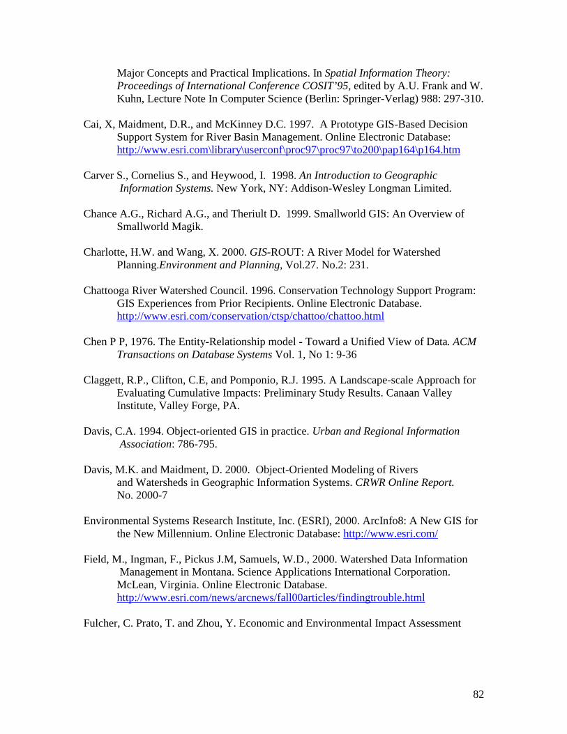
82
Major Concepts and Practical Implications. In Spatial Information Theory: Proceedings of International Conference COSIT’95, edited by A.U. Frank and W. Kuhn, Lecture Note In Computer Science (Berlin: Springer-Verlag) 988: 297-310.
Cai, X, Maidment, D.R., and McKinney D.C. 1997. A Prototype GIS-Based Decision
Support System for River Basin Management. Online Electronic Database: http://www.esri.com\library\userconf\proc97\proc97\to200\pap164\p164.htm
Carver S., Cornelius S., and Heywood, I. 1998. An Introduction to Geographic Information Systems. New York, NY: Addison-Wesley Longman Limited.
Chance A.G., Richard A.G., and Theriult D. 1999. Smallworld GIS: An Overview of
Smallworld Magik.
Charlotte, H.W. and Wang, X. 2000. GIS-ROUT: A River Model for Watershed Planning.Environment and Planning, Vol.27. No.2: 231.
Chattooga River Watershed Council. 1996. Conservation Technology Support Program: GIS Experiences from Prior Recipients. Online Electronic Database.
http://www.esri.com/conservation/ctsp/chattoo/chattoo.html Chen P P, 1976. The Entity-Relationship model - Toward a Unified View of Data. ACM Transactions on Database Systems Vol. 1, No 1: 9-36 Claggett, R.P., Clifton, C.E, and Pomponio, R.J. 1995. A Landscape-scale Approach for
Evaluating Cumulative Impacts: Preliminary Study Results. Canaan Valley Institute, Valley Forge, PA.
Davis, C.A. 1994. Object-oriented GIS in practice. Urban and Regional Information Association: 786-795.
Davis, M.K. and Maidment, D. 2000. Object-Oriented Modeling of Rivers and Watersheds in Geographic Information Systems. CRWR Online Report.
No. 2000-7 Environmental Systems Research Institute, Inc. (ESRI), 2000. ArcInfo8: A New GIS for
the New Millennium. Online Electronic Database: http://www.esri.com/
Field, M., Ingman, F., Pickus J.M, Samuels, W.D., 2000. Watershed Data Information Management in Montana. Science Applications International Corporation. McLean, Virginia. Online Electronic Database. http://www.esri.com/news/arcnews/fall00articles/findingtrouble.html
Fulcher, C. Prato, T. and Zhou, Y. Economic and Environmental Impact Assessment

83
Using a Watershed Management Decision Support Tool. Online Electronic Database: http://www.esri.com/library/userconf/proc97/proc79/to600/pap579/p579.htm
Gatti, R.C. and Richardson, M.S. 1997. Prioritizing Wetland Restoration Activity Within
a Wisconsin Watershed Using GIS Modeling. Journal of Soil & Water Conservation Vol. 54, No.3:537.
GE Smallworld, 2000. Smallworld GIS. Online Electronic Database:
http://www.smallworld-us.com/ Guptill, S.C, Boyco, K.J., Domaratz, M.A., Fegeas, R.G., Rossmeissl, H.J., and Usery,
E.L., 1990. An enhanced Digital Line graph Design: a Feature Based Data Model for Digital Spatial Databases that Represent Geographic Phenomenon. Circular 1048, United States Geological Survey. Reston, VA.
Hardy, P.G. 1999. Active Object Techniques for the Production of Multiple Map and
Geodata Products from a Spatial Database. Cambridge, UK: Laser-Scan Ltd. Hartnall, T. and MacAlister, B. 1998. Laser-Scan Limited, Cambridge, UK. Online
Electronic Database: http://www.laser-scan.com/utility.htm
He, J. Z. , Leung, S.K., and Leung, Y. 1999. A Generic Concept-based Object-oriented Geographical Information System. International Journal of Geographical Information Science Vol.13, No.5:475-498.
Hughes, J. G. 1991. Object-oriented Databases, New York: Prentice Hall. Imwalle, S.A. 1996. Maintaining a GIS: Critical Issues. American Water Resources
Association Symposium Proceedings: GIS and Water Resources. Herndon, VA.
Iseri, T.K. and Langbein B.W. 1995 General Introduction and Hydrologic Definitions: Watershed Manual of Hydrology: Part 1-Geological Survey Water Supply Paper 1541-A.41-A. Online electronic database.
Kemp, K. and McDonnell, R. 1995. International GIS dictionary. Cambridge, UK:
GeoInformational International. Kenneth, W. M. and Eric, W.S. 1997. Using GIS to Estimate Storm-water Pollutant Mass
Loadings. Journal of Environmental Engineering Vol. 123 No. 8: 737-749
Laser-Scan. 1998. Meeting Utility Needs Using Object-oriented Spatial Technology. Cambridge, UK: Laser-Scan, Ltd.
Laser-Scan. n.d. The Significance of Object-orientation in GIS. Laser-Scan, Ltd.
Cambridge, UK.

84
Laurini, R., and Thompson, D. 1994. Fundamentals Of Spatial Information Systems.
Academic Press, London.
Lovejoy, S.B. 1997. Watershed Management for Water Quality Protection: Are GIS and Simulation Models the Answer? Journal of Soil and Water Conservation.
Vol. 52. No.2:103-127 Maidment, D.R. 2000. ESRI Arc News: Consortium for GIS in Water Resources to
Design New Object Models. http://www.esri.com/news/arcnews/winter9900articles/32-consortium.html
Maidment, D. 2001. ArcGIS Hydro Data Model: Second Draft Data Model and Book Muniscript. Annual ESRI User Conference. San Diego, California.
McDonald A. 2001. ArcInfo8.1: Building a geodatabase. Environmental Systems Research Institute. Redlands, California. McDonald A. 1999. ArcInfo8.0: Building a geodatabase. Environmental Systems
Research Institute. Redlands, California. Milne, P., Milton, S. and Smith, J.L. 1993. Geographical Object-oriented Databases-a
Case Study. International Journal of Geographical Information Sciences Vol.7, No.1: 39-55.
National Hydrography Dataset Application Symposium. 2000. Online Electronic Database: http://www.crwr.utexas.edu/giswr/nhdconf/nationalhydro.html
Newell, R. n.d., Smallworld GIS: The Why and How of the Long Transaction. Pinson, L.J., and Wiener, R.S. 1988. Introduction to Object-oriented Programming and
Smalltalk. New York: Addison-Wesley Publishing Company.
United States Geological Survey, 2001. National Hydrography Dataset. Online Electronic Database: http://nhd.usgs.gov/index.html
United States Environmental Protection Agency. 1996. Why Watersheds? EPA Report Number EPAA800-F-96-001. Online Electronic Database: http://www.epa.gov/OWOW/watershed/why.html
United States Environmental Protection Agency. 1999. 1999. Watershed Protection: A Statewide Approach. Online electronic database: http://www.epa.gov/OWOW/watershed/statewide
United States Environmental Protection Agency. 2001. National Pollutant Discharge Elimination System (NPDES) Permit Program. Online Electronic Database. http://www.epa.gov/owm/gen2.htm

85
Viennaeau, A. 1999 ArcInfo8: Using ArcCatalog. Environmental
SystemsResearch Institute Inc. Redlands, California . West Virginia Department of Environmental Protection 1999. Online Electronic
database. http://www.dep.state.wv.us/watershed/ Wold, L.W. 1996. GIS and Watershed Analysis: Not just for Mapping Anymore! GIS
and Water Resources: American Water Resources Association. 23: 317-325.
Worboys, M.F. 1999. Relational Databases and Beyond-from Geographic Information Systems Volume1: Principles and Technical Issues. Edited by M.F. Goodchild, P.A. Longley, D.J., Maguire, and D.W., Rhind.
Worboys, M.F. 1995. GIS: A Computing Perspective. London, UK: Taylor and Francis
Ltd. Yourdon, E. 1994. Object-oriented Systems Design: An Integrated Approach. Englewood Cliffs, NJ: Yourdon Press.

86
APPENDIX A: Data Schema of the Monongahela Geodatabase

87
The Monongahela River Geodatabase Schema
Water Dataset
Wetlands EsriShape: Poly
NHD EsriShape: Line, Poly
HYDRO_24k EsriShape: Line,
Poly
Stream Network EsriShape: Line
Stream Annotation Stream Name
Hydro Network Enabled Geometric Network
Junction Object Ancillary Role
Ancillary Role None Sink
Source
Edge Object Junction to Junction
Simple Edge Object
Complex Edge Object
1 1
Environmental Dataset
Acid Mine Lands EsriShape:
Poly, Line, Point
CERCLIS EsriShape:
Point
NPDES EsriShape:
Point
TRI Cites EsriShape:
Point
TRI Database Non-Spatial Object
1 M
NPDES Annotation Permit Expiry Date
1 1
CERCLIS Annotation Company Name
1 1
Landbase Dataset
GNIS EsriShape: Point
Land Stewardship EsriShape: Poly
Road_24k EsriShape: Line
Jeep Trail EsriShape: Line
Rail Trail EsriShape: Line
Class4 Road EsriShape: Line
Class3 Road EsriShape: Line
Secondary Road EsriShape: Line
Primary Road EsriShape: Line
Road Network Enabled Geometric Network
1 M
Note: The numbers and letters on each box represent the relationship cardinalitiesbetween object classes. For example, “1-1” is a one-to-one whereas “1-M” is a one-to-many relationship