
Explicit routing schemes for implementation of cellular ... · PDF fileExplicit routing...
17
Natural Computing manuscript No. (will be inserted by the editor) Explicit routing schemes for implementation of cellular automata on processor arrays Jean-Vivien Millo · Robert de Simone Received: date / Accepted: date Abstract Massively Parallel Processor Array (MPPA) architectures are becoming widely available computing platforms. Because of formal similarities, they are good candidates for implementing Cellular Automata (CA). An essential difference still remains regarding the free- dom in communications. In MPPA there is a fixed on- chip network interconnection topology but every CA has its own definition of neighbourhood. While a cell in a CA can be considered as directly connected to its neighbours, these connections correspond to paths in the network of the MPPA. The communications need to be routed and scheduled to reach their proper desti- nation. In previous work we introduced a formal Data-Flow Process Network model named KRG (for K-periodically Routed Graph). Its main feature is to allow regular switching directives. In the present paper we will use it to represent the proper local sequences of routing di- rectives that will efficiently propagate values from cells to cells so as to implement the required CA neighbour- hood. We present the Neighbourhood Broadcasting Al- gorithm (NBA) that computes these routing directives. One should note here that the problem is made more complex as data traffic between distinct source and tar- get cells must be merged, while multicast may save a tremendous amount of communications when values are required in multiple locations. We demonstrate the expressive power of our formal- ism on the case of a 2D CA where the neighbourhood consists of all cells at Moore distance at most n. Further potential applications of our framework are hinted. EPI AOSTE, INRIA Sophia-Antipolis, 2004 routes des luci- oles BP93, 06902, Sophia-Antipolis, France Tel.: +33-4-92387965 Fax: +33-4-89732400 E-mail: {jean-vivien.millo, robert.de simone}@inria.fr Keywords Adequation Algorithm Architecture, Cellular automata, Data-Flow Process Network, Massively Parallel Processor Array, Network-on-Chip, Routing 1 Introduction Modern computing architectures are increasingly be- coming parallel platforms. While this trend is now well- established at the large scale of big parallel comput- ers, grid and now cloud computing, it is also pervad- ing all aspects of smaller scale architectures of the size of a single chip, with hardware accelerators such as DSPs, FPGAs and GPGPUs (Sangiovanni-Vincentelli and Passerone, 2012; Sriram and Bhattacharyya, 2009; de Micheli and Benini, 2006), or Massively Parallel Pro- cessor Arrays (MPPA) (Melpignano et al, 2012; Kalray, 2012) and many-core systems-on-chip. To make the best of such architectures, applications must exhibit as much potential parallelism, either explicitly of through early compilation analysis. The important question then be- comes one of efficient mapping of such applications onto such architectures. The approach has been described al- ready decades ago as Adequation (between) Algorithm and Architecture (AAA) (Grandpierre et al, 1999), and is also sometimes tagged as platform-based design or Y- chart design flow (Ferrari and Sangiovanni-Vincentelli, 1999), with the intention that the hardware platform is adjusted to the application just as much as the con- verse. In this context, Cellular Automata (CA) can be considered as one of the earliest modelling framework where massively parallel application descriptions were provided, with the implicit intention that they lead to efficient execution on matching parallel architectures.
-
Upload
hoangthuan -
Category
Documents
-
view
218 -
download
0
Transcript of Explicit routing schemes for implementation of cellular ... · PDF fileExplicit routing...

Natural Computing manuscript No.(will be inserted by the editor)
Explicit routing schemes for implementation of cellularautomata on processor arrays
Jean-Vivien Millo · Robert de Simone
Received: date / Accepted: date
Abstract Massively Parallel Processor Array (MPPA)
architectures are becoming widely available computing
platforms. Because of formal similarities, they are good
candidates for implementing Cellular Automata (CA).
An essential difference still remains regarding the free-
dom in communications. In MPPA there is a fixed on-
chip network interconnection topology but every CA
has its own definition of neighbourhood. While a cell
in a CA can be considered as directly connected to its
neighbours, these connections correspond to paths in
the network of the MPPA. The communications need
to be routed and scheduled to reach their proper desti-
nation.
In previous work we introduced a formal Data-Flow
Process Network model named KRG (for K-periodically
Routed Graph). Its main feature is to allow regularswitching directives. In the present paper we will use
it to represent the proper local sequences of routing di-
rectives that will efficiently propagate values from cells
to cells so as to implement the required CA neighbour-
hood. We present the Neighbourhood Broadcasting Al-
gorithm (NBA) that computes these routing directives.
One should note here that the problem is made more
complex as data traffic between distinct source and tar-
get cells must be merged, while multicast may save a
tremendous amount of communications when values are
required in multiple locations.
We demonstrate the expressive power of our formal-
ism on the case of a 2D CA where the neighbourhood
consists of all cells at Moore distance at most n. Further
potential applications of our framework are hinted.
EPI AOSTE, INRIA Sophia-Antipolis, 2004 routes des luci-oles BP93, 06902, Sophia-Antipolis, FranceTel.: +33-4-92387965 Fax: +33-4-89732400E-mail: {jean-vivien.millo, robert.de simone}@inria.fr
Keywords Adequation Algorithm Architecture,
Cellular automata, Data-Flow Process Network,
Massively Parallel Processor Array, Network-on-Chip,
Routing
1 Introduction
Modern computing architectures are increasingly be-
coming parallel platforms. While this trend is now well-
established at the large scale of big parallel comput-
ers, grid and now cloud computing, it is also pervad-
ing all aspects of smaller scale architectures of the size
of a single chip, with hardware accelerators such as
DSPs, FPGAs and GPGPUs (Sangiovanni-Vincentelli
and Passerone, 2012; Sriram and Bhattacharyya, 2009;
de Micheli and Benini, 2006), or Massively Parallel Pro-
cessor Arrays (MPPA) (Melpignano et al, 2012; Kalray,
2012) and many-core systems-on-chip. To make the best
of such architectures, applications must exhibit as much
potential parallelism, either explicitly of through early
compilation analysis. The important question then be-
comes one of efficient mapping of such applications onto
such architectures. The approach has been described al-
ready decades ago as Adequation (between) Algorithm
and Architecture (AAA) (Grandpierre et al, 1999), and
is also sometimes tagged as platform-based design or Y-
chart design flow (Ferrari and Sangiovanni-Vincentelli,
1999), with the intention that the hardware platform
is adjusted to the application just as much as the con-
verse.
In this context, Cellular Automata (CA) can be
considered as one of the earliest modelling framework
where massively parallel application descriptions were
provided, with the implicit intention that they lead to
efficient execution on matching parallel architectures.

2 Jean-Vivien Millo, Robert de Simone
While this has largely not occurred in the past because
of the lack of such existing efficient architectures, the
burst of new computing devices makes it worth a new
try.
Still, efficiency does not come for free because of new
emerging hardware, and parallelized systems may often
be only slightly faster, if not slower, than sequential
ones (while consuming more resources and power). One
can identify here several bottlenecks.
First, maximal concurrency inside the application
must be extracted, and carefully partitioned between
data and task parallelism. CA provide a formal Model
of Computation (MoC) where this has already been
achieved. Data-Flow Process Networks (DFPN), which
we shall later refer to, form another such formalism,
more aimed at the explicit representation of task paral-
lelism. Second, once the application has been described
in such a maximally concurrent fashion, a model of the
architecture must be provided at the same level, so as to
adjust the unrestrained concurrency of the application
to the physically limited parallelism of the execution
platform. Mapping then consists both of spatial distri-
bution allocation, and of temporal relative scheduling of
tasks that have to share the same processing resource.
Through mapping, a platform-independent application
becomes constrained as platform-aware. This design ap-
proach is pictured in Figure 1.
Parallel application
Abstract representation of the platform
MPPA architecture
Abstract algorithmic representation
Schedule Map
Route
Allocate
Platform aware algorithm
Platform specific Executable
Generate Code
Design
+
Fig. 1 Platform aware design flow for parallel algorithms
One aspect that is often neglected in the AAA ap-
proach, or at least downplayed, is the way necessary
data transfers are handled in the mapping. Just as com-
putation resources, communication resources are lim-
ited in size in physical architectures, so that mapping
in time and in space of such data communications onto
the existing interconnect structure needs to be defined
and optimized as well. This issue is well exemplified on
Cellular Automata, where any cell can be freely thought
as directly connected to its neighbours, while the un-
derlying target architecture might not allow such a pro-
fusion of connections. In fact this may be viewed as the
implementation issue of CA in our setting.
We shall consider the problem here in the case when
the execution platform consists of a 2D grid array of
homogeneous processors, connected by a local On-Chip
Network (NoC), with one router next to each proces-
sor being able to propagate data values further North,
South, East, West, and Here. First we will provide a for-
mal model of such architecture, mostly structural but
with definite behavioural aspects for the router nodes
(so that it may in a sense qualify as a Model of Com-
munication). The model is named KRG, after the K-
periodically Routed Graph scheme that allows provid-
ing regular switching patterns for the data transfers.
While there are countless results on the use of CA
to efficiently and adequately model applicative prob-
lems, impossible to be all quoted here, one should men-
tion that there are also efforts to use dedicated struc-
tural shapes of specific CA to model hardware micro-
architectural VLSI aspects (see for instance (Chaudhuri
et al, 1997)). Although certainly borderline to our con-
cerns, direct platform modelling with CA is out of our
current scope.
After this long preamble, we shall apply it to de-
scribe how mapping the data communications in a CA
can be mapped to our KRG model. As an example
we shall focus on a specific case, which in fact is very
frequently encountered in practice: the next-value of
each node of the CA depends symmetrically on all its
neighbours at Moore distance at most n. We shall pro-
vide a routing solution where data can be switched
and duplicated to some regular traffic, where ”regu-
lar” means: provided as a simple recursive pattern. This
solution, named by us ”Neighbour Broadcasting Al-
gorithm (NBA)” (Millo and de Simone, 2012b), has
very nice qualities: first, it optimizes traffic sharing;
second, successive data values are delivered in accor-
dance to their Manhattan distance. This last features
allows starting computing the local next-value ”on-the-
fly” when, for example, the impact of immediate neigh-
bours is ”very strong” and then decreases according to
the distance.
1.1 Related work
1.1.1 High level modelling of dataflow application
Many approaches (Glitia et al, 2012; Herrera and Villar,
2011; Marouf and Sorel, 2011; Davare et al, 2007; Eker
et al, 2003; Jantsch, 2008) provide formal frameworks
aiming at solving the issues of spatial and temporal al-
location (scheduling, mapping). These approaches use

Explicit routing schemes for implementation of CA on processor arrays 3
different DFPN to describe the parallel algorithm. Most
of these DFPN are based on the Marked Graph (MG)
model (Commoner et al, 1971). The MG model has
been extended into the K-periodically Routed Graph
(KRG) model (Boucaron et al, 2010) which enables the
handling of mapping and scheduling information (spa-
tial and temporal allocation). However none of these
models considers the routing of the communications
through the on-board communication medium. In this
paper, we extend the usage (but not the model itself!)
of KRG to support the routing information.
1.1.2 Implementing cellular automata on high
performance platforms
There are mostly two kinds of high performance plat-
forms considered for the implementation of cellular au-
tomata: the Field-Programmable Gate Array (FPGA)
(Kobori et al, 2001; Halbach and Hoffmann, 2004) and
the Graphics Processing Unit (GPU) (Rybacki et al,
2009; Zaloudek et al, 2009). The work presented in this
article is twofold. First, it gives a framework to con-
sider the mapping, scheduling and routing of any data
flow application on any platform. Thus the specific con-
straints related to GPU or FPGA implementation could
be considered in the framework however it is not the
scope of the paper. Second, the article considers the
mapping of a cellular automata application on a net-
work on chip. We postulate that network on chip is the
most appropriate platform to implement cellular au-
tomata.
1.1.3 Decoupling communication and computation in
cellular automata
The foundation of our work lies in the distinction be-
tween computation phases where the next state of a
cell is computed and communication phases where the
new state is sent to the neighbours. This decoupling
has been first considered by Olivier Boure et al. (Boure
et al, 2011) who analyse the evolution of cellular au-
tomata where perturbations occur. Any computation
or communication can succeed or fail according to a
given probability. In our framework, every computation
or communication occurs but it has to be scheduled and
routed.
1.2 Contribution
The first contribution of this paper is to raise the rout-
ing activity of the design flow at a high level of abstrac-
tion. The second contribution is to provide a framework
(the KRG model plus some generic constructions) to in-
tegrate the routing directives along with the mapping
directives into the description of the algorithm when it
has been expressed using the MG model. The last con-
tribution is the analysis of the NBA algorithm, which
results in the resolution of the routing activity with ex-
plicit routing directives for the specific case of cellular
automata based applications.
1.3 Outline
The remaining of the article is arranged as follow: Sec-
tion 2 introduces the Marked Graph (MG) and the K-
periodically Routed Graph (KRG) models. In Section
3, we present the constructions that model the possible
constraints coming from the platform (mostly mutual
exclusive access to shared resources). We also model
a network on chip using the KRG model and explain
how the communications of a given application can be
mapped and routed on it. In section 4, we perform the
full behavioural analysis of the communication in a cel-
lular automaton mapped on a MPPA based platform
with a NoC. The NBA algorithm is presented with the
resulting routing directive. Lastly, Section 5 presents
a few preliminary experimental results and Section 6
concludes this article with some perspectives.
2 Process networks: from Marked Graph to
K-periodically Routed Graph
Marked Graph (MG) (Commoner et al, 1971) is a pure
data flow process network used to model different kinds
of data flow applications. In particular, a finite CA with
a given size and a given definition of the neighbourhood
can be modelled as a MG where every cell is represented
as a transition. The firing of a transition corresponds
to the computation of the local update rule on the cell.
The MG model is adequate to express the logical
parallelism of an application. The logical parallelism is
the maximum parallelism that the application can offer
in term of computation but also in term of communica-
tion. On contrary, the deployment of such application
on an execution platform leads to adapt the logical par-
allelism to the “limited” parallelism of the platform.
The KRG model is an extension of the MG model that
is used to refine the MG description of the application.
Thanks to the new constructions of the KRG model, the
limitations of the execution platform will be directly in-
tegrated into the description of the application.

4 Jean-Vivien Millo, Robert de Simone
2.1 Marked Graph
The Marked Graph (MG) model (also known as Event
Graph) is a graph in which any vertex has a type. It
is either a transition or a place. This last holds tokens.
The edges of a MG are directed, they are hence called
arcs. An arc in a MG cannot connect two vertices of
the same type.
Definition 1 (Marked Graph)
A marked graph is a structure G = 〈T, P, F,M0〉where
– T is a set of transitions.
– P is a set of places. T ∩ P = ∅.– F ⊆ (T ×P )∪ (P ×T ) is a set of arcs. If t ∈ T and
p ∈ P , (t, p) and (p, t) are two arcs resp. from t to
p and from p to t.
– M : P → N is a marking. M0 is its initial marking.
– Each place has exactly one incoming and one out-
going arcs: ∀p ∈ P , |{(t, p) | ∀t ∈ T}| = |{(p, t) |∀t ∈ T}| = 1.
The constraint on the number of inputs and out-
puts of every place guarantees that a token can be used
by only one transition. Consequently, the MG is said
conflict-free (or deterministic).
In the scope of this article, a MG models an applica-
tion where the transitions represent the different tasks
that can be performed concurrently in the application.
The places represent the interconnection buffers. The
arcs represent the data flows from task’s outputs to in-
terconnection buffers and from interconnection buffers
to task’s inputs. By extension, the sequence arc-place-
arc between two transitions represents a data depen-
dency between two tasks. The presence of a token in a
place represents the availability of a data element in the
interconnection buffer. A transition without incoming
(outgoing) arc represents a global input (resp. output)
of the application.
Figure 2 presents a MG with five transitions (dis-
played as rectangles) and five places (displayed as ovals).
Two of these places contain one single token (displayed
as black dots). The application represented in Figure
2 is a proportional-integral-derivative controller (PID
controller) with an auto adaptive command. It gets a
data, such as a speed, from a sensor, it computes (-/+)
the difference with the expected speed and generates a
command using a PID block. The command is set to an
actuator and feedback to the command that compute
the next expected speed according to the behaviour of
the system. For example, if the expected speed can-
not be reached because of a sporadic event external to
the system, it takes the decision to reduce the expected
speed so that the system will reach a stable state any-
how. Later, the expected speed can be set back to its
nominal value.
-/+
command
PID
get
set
(100)w
(010)w
(001)w
(001)w
(001)w
Fig. 2 A marked graph
Notation 2 (Predecessor, successor)
Let G be a MG, t ∈ T and p ∈ P . We note :
– •t is the preset of t, •t = {p | (p, t) ∈ F}.– t• is the postset t, t• = {p | (t, p) ∈ F}.– •p is the transition which precedes p, •p = t such
that (t, p) ∈ F .
– p• is the transition which succeeds p, p• = t such
that (p, t) ∈ F .
2.2 Execution semantics of a MG
The execution semantics of a MG is based on a logical
time with a synchronous semantics (Millo and de Si-
mone, 2012a). At the instant 0, the MG is in its ini-
tial marking. Then, an execution step leads to another
marking at instant 1. Every subsequent execution step
entails a new marking. During a given execution step,
many firable transitions can be fired simultaneously
(synchronously) but each transition can be fired only
once.
Definition 3 (Firable transition in a MG)
In a MG G, a transition t ∈ T is firable at a marking
M if ∀p ∈ •t, M(p) > 0. A source is always firable. FM
is the set of firable transitions at a marking M .
Definition 4 (Execution model of a MG)
Let G be a MG and M its current marking. An execu-
tion step is a transition relation from M to M ′ denoted
MFT−→M ′ with FT ⊆ FM , ∀p ∈ P ,
M ′(p) = M(p) + FT (•p)− FT (p•). (FT (t) = 1 if and
only if t ∈ FT . FT (t) = 0 otherwise).

Explicit routing schemes for implementation of CA on processor arrays 5
An execution (Exec) of a MG is a finite or infinite
sequence of execution steps:
Exec = M0FT1−→ M1
FT2−→ M2FT3−→ ...
FTi−→ MiFTi+1−→ ...
where FTi ⊆ FMi−1.
An execution is said As Soon As Possible (ASAP)
when for every instant i, FTi = FMi−1
Definition 5 (Scheduling and schedule)
Let G be a MG with an execution Exec. Let t ∈ T be
a transition of G. The schedule of t is the binary word
relating the activity of t:
Sched(t) = FT1(t).FT2(t) · · ·FTi(t) · · · .The scheduling of G for an execution Exec is the map-
ping t→ Sched(t) | ∀t ∈ T .
Remark 6 (Scheduling and execution)
The subsequent steps of an execution can be deduced
from its scheduling. Consequently, a scheduling defines
an execution and vice versa.
Figure 3 presents the same MG than in Figure 2
but with the schedule of each transition attached to it
as binary words. (u)ω means the infinite repetition of
the word u ((u)ω = u.u.u . . . )
-/+
command
PID
get
set
(100)w
(010)w
(001)w
(001)w
(001)w
Fig. 3 A Scheduled marked graph
2.3 K-periodic routing pattern
Routing patterns are introduced in the form of infinite
binary sequences. 1 stands for left, 0 for right. Alterna-
tively, 0 and 1 can represent then and else, or up and
down.
Definition 7 (Binary words)
We note B = {0, 1} the set of Boolean values, B∗ the
set of finite binary words (sequence of Boolean values),
B+ the set of non-empty words, and ε the empty word.
Definition 8 (Infinite binary sequences)
Let Bω be the set of infinite binary sequences (that is,
sequences of Boolean values). An infinite sequence s ∈Bω is called ultimately periodic iff it is of the form u.vω,
with u ∈ B∗ and v ∈ B+; u is called the initial part of
w, and v its periodic (or steady) part.
We note Pkp the set of ultimately periodic binary
sequences (k-periodic sequences) with a steady part of
length p containing k occurrences of “1”. We call k the
periodicity and p the period of such sequences. Finally,
let P be the set of k-periodic sequences.
2.4 K-periodically Routed Graph
K-periodically Routed Graph (KRG) is an extension
of MG, where two kind of routing nodes inspired from
BDF (Parks, 1995) are introduced: Select (demux) and
Merge (mux). But whereas branching conditions in BDF
are left unspecified, they are defined by n-synchronous
(Cohen et al, 2006) binary sequences, in our case, com-
puted off-line. They carry stronger information about
routing than in CSDF (Bilsen et al, 1995). KRG is de-
terministic, and let us check on design safety (bounded
resources, liveness) (Coadou, 2010).
In the scope of this article, the KRG model is used to
refine the MG description of a data-flow application by
introducing constraints coming from the execution plat-
form. These additional constraints will be represented
using the newly introduced Select and Merge nodes.
Definition 9 (K-periodically Routed Graph)
A K-periodically Routed Graph is a structure
〈N , Se,Me, P,M0, SwitchCond〉, such that:
– N is a finite set of transition.
– Se is a finite set of Select nodes such that ∀ se ∈Se : |se•| = 2 and |•se| = 1.
– Me is a finite set of Merge nodes such that ∀me ∈Me : |me•| = 1 and |•me| = 2.
– SwitchCond is a function Me ∪ Se→ P.
– P is a finite set of places such that
P ⊂ (N ∪ Se ∪Me)×(N ∪ Se ∪Me) and ∀ p ∈ P :
|p•| = |•p| = 1.
P0 ⊆ P is the set of instantaneous places.
– M0 : P → N is the initial marking of places.
We call a KRG k-periodic due to the fact that all switch-
ing conditions (SwitchCond patterns) are k-periodic se-
quences.
∀X, Y ∈ {N , Se,Me, P}, X 6= Y → X ∩ Y = ∅
An instantaneous place is a specific kind of place
that can be passed through instantaneously. Let p ∈ P0
be an instantaneous place, when •p is fired, it generates

6 Jean-Vivien Millo, Robert de Simone
a token in p and allows p• to be fired within the same
execution step. The instantaneous places are graphi-
cally represented as an oval similarly to normal places
but without black border.
The notion of execution step is consequently revised
compared to MG to be a sequence of micro-steps where
some firable nodes (transitions, Select, and Merge) are
triggered at the first micro-step. Then, the transition
that becomes firable due to the production of tokens
in instantaneous places can be fired at the next micro-
steps. When a token is produced in a non-instantaneous
place, it will be usable only at the next step. This exe-
cution semantics correspond the one of the synchronous
languages (Benveniste et al, 2003) such as Esterel, Lus-
tre or Signal.
Definition 10 (KRG firing rule)
The firing condition for transitions is the same than in
a MG: firing a transition n implies the consumption of
a token in each place of •n, and the production of a
token in each place of n•;
A Select node is firable when there is a token in input.
A Merge node m is firable when there is a token in
the input x and x is the first letter of SwitchCond(m).
Select node s fires by consuming the first letter x ∈ Bof
SwitchCond(s) and an input token, producing a token
on the output x place.
Merge node m fires by consuming the first letter x ∈ Bof SwitchCond(m) together with the token on input x,
and then produces a token on the output.
In the sequel we will use n-ary select and merge
nodes. n-ary nodes are the straightforward extension of
the binary select or merge nodes but to respectively n
inputs (outputs). The switching conditions are thus in-
finite words composed of n different letters. The formal
definition of n-ary select and merge nodes are presented
in the thesis of Anthony Coadou (Coadou, 2010).
Let us consider the application described in Figure
2 as a MG and the following set of processing elements
Pe = {Sensor,Actuator,DSP,CPU}. The KRG in
Figure 4 is a refinement of the application of Figure
2 including the mutual exclusive access of -/+ and PID
to the processing element DSP . If we focus our interest
on the box DSP , the token in the place between the
merge and the select node represents the usage of the
DSP. At the first iteration, the select node dispatches
the token to its output labelled with 1 which allows the
task -/+ to fire. Then, the merge node consumes the
token and sends it back to its initial position. At the
second iteration, the token is sent to PID and comes
back. The switching conditions of both the select and
the merge nodes are the same (10)ω but, in general,
-/+
command
PID
0
1
0
1
get
set
Sensor
Actuator
CPU DSP
(10)w (10)w
Fig. 4 The application represented by the MG of Figure 2as been enriched with computation mapping information.
every node has its own. The well-construction of the
switching conditions is essential to guarantee the live-
ness of the system. For example, let us assume that
on the current example the switching condition of the
merge node is replaced by (01)ω. After the firing of -/+
the token would be stuck in input of the merge node be-
cause this last is waiting for a token on its other input.
This situation leads to a deadlock on that example.
The KRG of Figure 5 is an additional refinement of
the application described in Figure 2 where CPU and
DSP communicate through a bus. So the exchanges
between these two processing elements alternate. Simi-
larly to Figure 4, the construction presented in the box
Bus represents the mutual exclusive access to the com-
municating element. When -/+ and PID have fired, the
token is sent on the bus to CPU , command is executed
and the produced token is sent back to DSP through
the bus again.
3 Mapping data-flow applications on an
execution platform using the KRG model
The mapping consists in associating the transitions and
places of the original MG that describes the tasks and
the interconnections of the application to processing
and communicating elements of the execution platform.
In the scope of this paper, the authors discuss how a
given mapping can be integrated into the description of
the application using the KRG model. The problem of
finding the best mapping for a given application on a
given platform with respect to some optimization cri-
teria is out of the scope of this paper.

Explicit routing schemes for implementation of CA on processor arrays 7
Sensor
DSP
Actuator
CPU
-/+
command
PID
0
1
0
1
0
1
0
1
get
set
Bus
(01)w (10)w (10)w (10)w
Fig. 5 The application represented by the KRG of Figure 2 as been further enriched with communication mapping information.
3.1 Mapping transitions to processing elements
Let Pe be a set of processing elements. A mapping
is a (total) function from N to Pe. Let n ∈ N be
a transition, PM(n) denotes the processing element
p ∈ Pe that allocates n. We define the function PM−1
from Pe to 2N that associates to every processing el-
ement p ∈ Pe, the set of transitions allocated on it
PM−1(p) = {n | PM(n) = p}.
When two or more transitions are mapped to the
same processing element, they cannot execute at the
same time. This semantics can be captured in KRG
using the construction presented in Figure 6. This con-
struction adds to each of the n transitions an incoming
and an outgoing arcs without modifying the existing
ones. The token represents the usage of the process-
ing element. The n-ary word u(v)ω gives the order into
which the transitions are going to be execution on the
processing element. For example, (12...n)ω would exe-
cute sequentially each transition in their numeric order
while 12(344)ω would initially process transition 1 then
transition 2 and then, the sequence transition 3 followed
by twice transition 4 would be repeated forever.
The refinement of the application described in Fig-
ure 2 with the mapping of transitions to processing el-
ements is given in Figure 4. The function PM is not
given but can be easily deduced from Figure 4. The
transitions get, set, and command are mapped to a ded-
icated processing element. No additional construction is
required. The element -/+ and PID have been mapped
to DSP ; the construction presented in Figure 6 has
been used.
2
1
… n
…
2 1
…
n
…
…
…
u(v)w u(v)w
…
Fig. 6 The n transitions are mapped to the same processingelement.
3.2 Mapping places to communicating elements
We consider four kind of communicating elements for
the mappings of the communications: the point to point
connection, the bus, the internal memory and the net-
work on chip. We let to the user the care of extending
this work to other kind of communicating elements.
Each place of the original model of the application is
mapped to one of these elements. Formally, a mapping
is a (total) function from P to Ce. Let p ∈ P be a place,
CM(p) denotes the communicating element c ∈ Ce that
allocates p. We define the function CM−1 from Ce to
2P that associates to every communicating element c ∈Ce, the set of places allocated on it CM−1(c) = {p |CM(p) = c}.
The set of communicating elements Ce is the union
of the following sets:
– P2P , the set of point to point connections where
each allocates a single place:
∀p2p ∈ P2P , |CM−1(p2p)| = 1.
– B the set of buses where each may group many
places.

8 Jean-Vivien Millo, Robert de Simone
– MPe the set of internal memories. Let p ∈ P be
a place and proc ∈ Pe be a processing element. If
{•p, p•} ⊆ PM−1(proc), then the communications
between •p and p• are mapped to the internal mem-
ory of the processing element proc.
– NoC the set of networks on chip where each may
group many places.
The semantics of a place, as it is defined in the origi-
nal MG model, matches with the point to point commu-
nication and with the internal memory. Consequently
there is no transformation of the model required for
these two kind of communicating elements. However,
the buses and networks on chip have a different seman-
tics that can be expressed in KRG with the transfor-
mations given below.
3.2.1 Mapping places to a bus
A bus allows only one communication at a time. Thus
there is a mutual exclusion between the places mapped
to the same bus. Figure 7 presents the transformation to
perform on the original model in order to capture the
semantics of a bus. Initially, there were m horizontal
places from left transitions to the right transitions at
the same level. Now, the m communication should go
through the single place in between the merge and the
select transition in a given order specified by u(v)ω.
2
1
… m
…
2 1
…
m
…
…
…
u(v)w u(v)w
…
…
Fig. 7 The m places are mapped to a bus.
The refinement of the application described in Fig-
ure 2 with the mapping of places to communicating
elements1 is given in Figure 5. The function CM is
not given but can be easily deduced from Figure 5. The
places in output of get and in input of set are mapped to
point to point connections. The place between -/+ and
PID is mapped to the internal memory of DSP . The
two last places are mapped to a bus. The construction
presented in Figure 7 has been used.
3.2.2 Mapping places to a network on chip
A network on chip is a mesh (or a torus) of routers
where each is connected to its four direct neighbours
on the grid. Each router is also connected to a local
1 in addition to the mapping of transitions to processingelements
processing element that runs some of the tasks of the
original MG. Figure 8 captures the structure and the
semantics of a network on chip in KRG. The square
boxes are routers with five bi-directional channel de-
noted North, West, South, East, and Local. Local de-
notes the connection from the current router to the
transitions that are computed by the local processing
elements. There is m places in output of all these tran-
sitions that are connected to the network. The local
merge orders the emission of tokens on the network
according to the switching condition u(v)ω. Similarly,
there are n places in input of all these transitions that
get tokens from the network. The local select node or-
ders the reception of token from the network according
to its switching condition u′(v′)ω. The content of the
router box is detailed below.
2
1 …
m
…
u(v)w
2
1 …
n
…
u’(v’)w
To the local transitions
From the local transitions
Fig. 8 Representation of a network on chip in KRG.
For example, let us consider a MG composed of 128
transitions. Among them, Transition A is connected to
Transition B. This MG is mapped to a platform com-
posed of 64 processing elements connected through a
network on chip. First, all the transitions are mapped
to the 64 processing elements (2 transitions each). If
there exist a direct connection (a place) between two
transitions mapped on the same processing element, the
connection is assumed to be done through the internal
memory of the processing element. The corresponding
place appears on the KRG as it is in the MG. All the
remaining connections are mapped to the network on
chip. Let say that Transition A is mapped on the first
processing element and transition B is mapped on the
fifth processing element. When Transition A fires, it
generates a token that is consumed by the local merge.
Then the token is sent to the router and travels on
Explicit routing schemes for implementation of CA on processor arrays 9
the network until it reaches the router that is directly
connected to the fifth processing element. This router
sends the token to the local select node that consumes
it. Lastly, the token arrives in the place in input of
Transition B.
The network is subject to a correctness rule that
is (1) every connection mapped to the network adds
an input to a local merge node and an output to a
local select node. Formally, let us consider a network
on chip of size (X,Y ), ∀i ∈ [1, X] and ∀j ∈ [1, Y ],
n(i,j) is the number of outgoing places from the location
(i, j). m(i,j) is the number of incoming places from the
location (i, j). We have
ΣXi=1Σ
Yj=1n(i,j) = ΣX
i=1ΣYj=1m(i,j) (1)
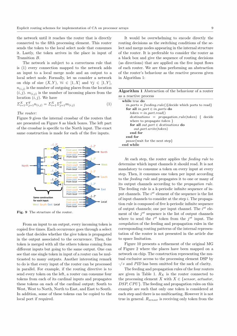
The router:
Figure 9 gives the internal crossbar of the routers that
are presented on Figure 8 as black boxes. The left part
of the crossbar is specific to the North input. The exact
same construction is made for each of the five inputs.
CO
PY
East
North
South West Local
X
…(…)w
X
…(…)w
X
…(…)w
X
…(…)w
0 1
0
1
0 1
0
1
X
…(…)w
0 1
North
South
East
West
…(…)w
…(…)w
…(…)w
…(…)w
Local
…(…)w
E L W
S N
E L
W S
N
E L W
S N
E L
W S
N
E L W
S N
From west
From west
From west
From west
From south
From south
From south
From south
From east
From east
From east
From east
From local
From local
From local
From local
From local
From east
From south
From west
Same construction for each input:
Fig. 9 The structure of the router.
From an input to an output, every incoming token is
copied five times. Each occurrence goes through a select
node that decides whether the give token is propagated
in the output associated to the occurrence. Then, the
token is merged with all the others tokens coming from
different inputs but going to the same output. One can
see that one single token in input of a router can be mul-
ticasted to many outputs. Another interesting remark
to do is that every input of the router can be processed
in parallel. For example, if the routing directive is to
send every token on the left, a router can consume four
tokens from each of its cardinal inputs and propagates
these tokens on each of the cardinal output: South to
West, West to North, North to East, and East to South.
In addition, some of these tokens can be copied to the
local port if required.
It would be overwhelming to encode directly the
routing decisions as the switching conditions of the se-
lect and merge nodes appearing in the internal structure
of the router. It is preferable to consider the router as
a black box and give the sequence of routing decisions
(as directions) that are applied on the five input flows
of each router. We are thus performing an abstraction
of the router’s behaviour as the reactive process given
in Algorithm 1:
Algorithm 1 Abstraction of the behaviour of a router
as a reactive processwhile true do
in ports = feeding rule(){decide which ports to read}for all in port ∈ in ports do
token = in port.read()destinations = propagation rule(token) { decidewhere to propagate token }for all out port ∈ destinations do
out port.write(token)end for
end forpause{wait for the next step}
end while
At each step, the router applies the feeding rule to
determine which input channels it should read. It is not
mandatory to consume a token on every input at every
step. Then, it consumes one token per input according
to the feeding rule and propagates it to one or many of
its output channels according to the propagation rule.
The feeding rule is a k-periodic infinite sequence of in-
put channels. The ist element of the sequence is the list
of input channels to consider at the step i. The propaga-
tion rule is composed of five k-periodic infinite sequence
of output channels; one per input channel. The ist ele-
ment of the jst sequence is the list of output channels
where to send the ist token from the jst input. The
compilation of the feeding and propagation rules in the
corresponding routing patterns of the internal represen-
tation of the router is not presented in the article due
to space limitation.
Figure 10 presents a refinement of the original MG
of Figure 2 where the places have been mapped on a
network on chip. The construction representing the mu-
tual exclusive access to the processing element DSP by
-/+ and PID has been omitted for the sack of clarity.
The feeding and propagation rules of the four routers
are given in Table 1. RX is the router connected to
the processing element X with X ∈ {sensor, actuator,DSP, CPU}. The feeding and propagation rules on this
example are such that only one token is considered at
each step and there is no multicasting. However it is not
true in general. Rsensor is receiving only token from the

10 Jean-Vivien Millo, Robert de Simone
1
0
(01)w
1
0
(01)w
Sensor Actuator
CPU DSP
get set
command
Network on chip
-/+
PID
Fig. 10 The original application is mapped to a network onchip.
local port and send them to the east. When Ractuator re-
ceives these token on its west port, it propagates them
on the south toward the DSP. Another path through
RCPU would have been chosen however, the channel
from RCPU to RDSP is already used for the exchanges
of tokens between CPU and DSP . We choose to disso-
ciate the paths as much as possible.
Router Feeding rule Propagation ruleRsensor (L)ω (E)ω
Ractuator (WS)ω (SL)ω
RDSP (LE)ω (EL)ω
RCPU (WNLL)ω (LLNW )ω
Table 1 The feeding and propagation rules associated toFigure 10
When the new configuration of a cellular automaton
is computed, the state of every cell has to be duplicated
and sent to its neighbourhood. The representation of
such behaviour in MG required to explicitly use a copy
transition that takes one token (the state) in input and
generates several copies. While mapping the cellular au-
tomaton represented as a MG to a MPPA with an on-
chip network, the copy transition can be absorbed by
the routers. Instead of explicitly copying the state and
sending several tokens on the network, only one token
is sent and the routing directive shall be to duplicate
this token whenever required. See Section 4 for details.
3.3 Routing and Scheduling
The mapping of an application on a platform intro-
duces select and merge nodes but also additional in-
termediary places in the system. The next step is to
compute the switching pattern of these nodes in or-
der to define 1/ the order into which the transitions
on the same processing element fire 2/ the order into
which the tokens go through the bus (if any) 3/ the
feeding and propagation rules of the routers of the Noc
(if any) 4/ the new schedule of every node (transition,
select and merge). These pieces of information can be
deduced from a co-simulation of the original model with
the refined model. Each step of execution of the original
model will be associated to a sequence of steps in the
refined model where the operations occurring in parallel
in the original model but mapped to the same process-
ing element are sequentialized. This method, used to
derive the scheduling information, needs to be comple-
mented with a method to efficiently compute the rout-
ing of the data on the network. Section 4 presents an
example of a cellular automaton mapped on a MPPA
with an on-chip network. We then present the Neigh-
bour Broadcasting Algorithm (NBA) that aims at pro-
viding an efficient routing scheme through the on-chip
network for the specific case of cellular automata.
4 Routing cellular automata
Many applications such as the game of life (Gardner,
1970) or the class of stencil computation (Datta et al,
2008) consist of a regular grid of tasks communicat-
ing with each other. In such applications, the state of
a task depends upon the previous states of its direct
neighbourhood. Sometime, not only the direct neigh-
bourhood is considered but also some indirect neigh-
bours matching a given stencil. In the worst case, every
task needs to know the state of its neighbours up to a
distance n. In the sequel, we consider CA based appli-
cation where the notion of neighbourhood is extendedto all the cells up to a distance n.
4.1 Cellular automata
Let us consider synchronous cellular automata where
the underlying topology is a finite rectangular grid of
cells of dimension two (Kari, 2005; Dennunzio, 2012).
We assume the topology to be a torus (the opposite
sides are glued together).
Let ca and cb be two cells identified by their vector of
coordinates respectively ca = (xa, ya) and cb = (xb, yb)
. Let diff = (xdiff , ydiff ) be the difference between caand cb: diff = ca−cb = (xa−xb, ya−yb). The distance
relative to the dimension (or coordinate) x (resp. y) is
|xdiff | (resp. |ydiff |).The Manhattan distance (or norm) between ca and
cb is denoted ||diff ||1 and is equal to
||diff ||1 = |xdiff |+ |ydiff |

Explicit routing schemes for implementation of CA on processor arrays 11
The Moore distance (or norm) between ca and cbis denoted ||diff ||∞ and is equals to
||diff ||∞ = max(|xdiff |, |ydiff |)
In the scope of this paper, we define the neighbour-
hood of a cell based on the Moore distance as follows.
Nn(c) is the neighbourhood of the cell c up to a radius
n (c is in its own neighbourhood).
Nn(c) = {c′ such that ||c− c′||∞ ≤ n}
The size of the neighbourhood Nn(c) is |Nn(c)| = (2 ∗n+ 1)2.
Every cell c takes its state in a finite set of states
denoted S. The configuration of the automaton is a
mapping conf : Z2 → S that refers to the state of ev-
ery cell. The evolution of the automaton occurs syn-
chronously on discrete time steps. All tasks are up-
dated simultaneously according to the local rule. The
local rule is a function localRule : Sk → S where k
is the size of the neighbourhood (here k = |Nn(c)|).At every time step, the local rule is applied in every
cell and the new states are computed to be conf ′(c) =
localRule(conf(c+x1), conf(c+x2), . . . , conf(c+xk))
where {∀i ∈ [1, k], xi} is a set of vectors addressing the
relative distance between c and each of its neighbours.
The new configuration of the automaton is thus conf ′.
The computation of the local rule requires to get
the states of all the neighbours. Since the cells are up-
dated synchronously, every cell needs to know the states
of all its neighbours simultaneously. When considering
the implementation of a CA on a MPPA with an on-
chip network, every cell simultaneously broadcasts its
state to all its neighbours in order to allow them to
update. The performances of this system will highly
depend upon the efficient routing of the data traffic on
the network. In the sequel, we introduce the KRG of a
CA mapped on an MPPA with an on-chip network. We
propose the NBA as the optimal routing solution and
we analyse the behaviour of this system with respect to
time and space.
4.2 Modelling cells and CA in KRG
Figure 11-a presents the model of a cell where there
are point to point connections 1/ from each of the m
cells in the neighbourhood and 2/ to each of the m cells
that need the state of the current cell to update2. We
let the reader thinks about the shape of the full cellular
automaton when the radius of the neighbourhood has
a radius superior to one.
2 this set of cells is different from the neighbourhood whenit is not a regular grid
2 1
…
m
…
(12…m)w
…
copy
From local port of the router
2 1
…
m
…
(12…m)w …
Towards local port of the router
Loca
lRu
le
…
cop
y …
From the m neighbours
To the m neighbours
LocalRule
2 1
…
m
…
(12…m)w
…
From local port of the router
Towards local port of the router
a)
2 1
…
m
…
(12…m)w
…
copy
From local port of the router
2 1
…
m
…
(12…m)w …
Towards local port of the router
Loca
lRu
le
…
cop
y …
From the m neighbours
To the m neighbours
LocalRule
2 1
…
m
…
(12…m)w
…
From local port of the router
Towards local port of the router
b)
Fig. 11 The model of a cell before mapping and after map-ping on a network on chip.
4.3 Mapping a cellular automaton on a network on
chip
Figure 11-b presents the KRG model of a cellular au-
tomaton mapped on a network on chip. First, the cell
sends its state (abstracted as a token) through the net-
work to all the cells that requires it to update. The
task of duplicating the token is left to the multicasting
ability of the routers as explain earlier. Then, the cell
receives the m tokens required to compute its new state
and updates.
Concerning the mapping of the cells on processing
elements, we assume in the scope of this paper that
there is as much processing elements as cells. Even
through this hypothesis is not much realistic regard-
ing the off-the-shelf platform; it enables us to perform
the routing analysis without the additional problemof multi-scaling (when a grid of cells is allocated to
each processing element). In addition, this hypothesis is
more realistic while considering the implementation of
this model on hardware or FPGA (Kobori et al, 2001).
The following results remain helpful in these conditions.
4.3.1 Neighbourhood Broadcasting Algorithm (NBA)
NBA is a 2-dimensional propagation algorithm for cel-
lular automaton based applications that simultaneously
sends a token from every single cell to all their neigh-
bours up to a given radius. NBA sends a single to-
ken per cell and then broadcasts to all the other cells
through the network. The idea behind this exercise is
that the propagation pattern for any kind of neighbour-
hood where the furthest neighbour is at a radius n can
be deduced from the propagation pattern of the NBA
with a radius n.
Figure 12 shows how a single token is propagated
through the mesh up to a certain Moore distance. The

12 Jean-Vivien Millo, Robert de Simone
1 2 3 4 5 6
Fig. 12 The broadcasting pattern from a single token.
path from a given source to a given destination always
follows one coordinate direction fully, then the other
one. The token always turn left at this change of di-
rections, i.e. counter-clockwise. On the third picture of
Figure 12, the top-most, bottom-most, left-most, and
right-most routers are at a Manhattan distance n(= 3)
from the source. So on the fourth picture, the data are
not propagated straight but only left.
Another thing to notice is that traffics originating
from North and South (resp. East and West) never in-
terfere in the same router. Northbound tokens only use
South and East channels, southbound ones the North
and West channels instead. Figure 13 presents the only
four propagation patterns among all (modulo rotation)
that are used to realize the NBA. In these four patterns,
the token is sent to the local port. In B and D, it is sent
straight, lastly, in C and D it is multicasted on the left
branch.
A B C D
Fig. 13 The four token propagation patterns for the NBA.
Pattern D is applied when a token comes from a
neighbour straight behind the current position; excepted
when a Manhattan distance n has been reached, in such
a case, Pattern C is applied. Pattern B is followed when
a token has already turned left once. Then when it has
covered n steps after turning left, Pattern A is followed
which terminates the propagation.
The tokens processing along vertical directions (resp.
horizontal) can be parallelized in the same step.
The feeding rule is the following:
1. At the first step, a router reads its local port (and
broadcasts the data in every cardinal direction),
2. At the even steps, the North and South input ports
are processed.
3. At the odd steps, the East and West input ports are
processed.
The feeding rules is summarized by the following
expression:(L(NS
E
W
)x)ω(where x is the number of
steps required to propagates all the token in input of
the router).
NBA consists in a set of routing directives (the prop-
agation rule) that every router follows. The resulting
global behaviour will be the one presented in Figure 12
but for every router simultaneously.
The propagation rule is the following (n is the radius
of the neighbourhood):
1. If the data comes from a straight neighbour (the
secondary coordinate equals 0) :
(a) If the data comes from a distance n relative to
the main direction, it follows Pattern C of Figure
13.
(b) If the data comes from less than a distance n
relative to the main direction, it follows the Pat-
tern D of Figure 13.
2. If the data does not come from a straight neighbour
:
(a) If the data comes from a distance n relative to
the secondary direction, it follows the Pattern Aof Figure 13.
(b) If the data comes from less than a distance n
relative to the secondary direction, it follows the
Pattern B of Figure 13.
The propagation rule is given in Section 4.3.3 as
a sequence of decisions (similarly to Table 1 for the
PID controller) that has been computed statically for
a radius 5. The propagation rule is derived from the
following analysis of the NBA.
4.3.2 Analysis of the NBA in time and space
Let us focus on the traffic generated at the input port of
a router while running NBA. First, it appears that the
tokens arrive in the order of their Manhattan distance
from their source. The evolution of the traffic can be
divided in stages. The ist stage starts when the input
channel of the studied port contains the tokens from a
Manhattan distance i. The stage ends when all these

Explicit routing schemes for implementation of CA on processor arrays 13
tokens have been routed. As a indirect consequence, at
the end of the ist stage, the channel contains the tokens
from a Manhattan distance i+ 1 only. Figure 14 shows
which tokens are present in the channel at the beginning
of each stage. Figure 14 focuses on the right top corner
of a neighbourhood with a radius n = 5 (N5(r)).
Stage 1
Stage 2
Stage 3
Stage 4
Stage 5
Stage 6
Stage 7
Stage 8
Stage 9
Stage 10
r Fig. 14 The origin of the tokens in input of the North portof a router r stages after stages.
Initially, every router broadcasts the tokens from
their local port in every direction. Consequently, at the
first stage, every router gets the tokens from its direct
neighbours in each of its input port. These tokens are
multicasted straight, left and to the local port because
they come from a straight neighbour.
At the second stage, every router gets two tokens in
each of its input port. The first token in the channel
has to be multicasted because it comes from a straight
neighbour but the second should not. So it generates
three tokens in each input port.
At stage n (Step 5 in Figure 14), each router has
in its input channel a token from a straight neighbour
at a Manhattan distance n. This token is propagated
left but not straight. It corresponds to the case (1.-(a))
of the routing directives (Section 4.3.1). The four other
tokens are propagated straight only.
At stage n + 1 onward, each router receives some
tokens coming from the neighbours at a distance n rel-
ative to the main direction. These tokens are not prop-
agated but only sent to the local port. However, the
router also receives some tokens that have to be for-
warded straight but none of them is multicasted on the
left anymore because they do not come from a straight
neighbour.
Theorem 11 (Time and space allocation)
For a radius n, NBA execution takes 2 ∗ n ∗ (n + 1)
steps to complete. In addition, a capacity n for every
interconnection buffer is enough.
Proof Let c be a cell of the application and r its router.
c has (2 ∗ n + 1)2 neighbours (including it). Each port
of r receives tokens from a quarter of the neighbours
(n ∗ (n+ 1) = (2 ∗ n+ 1)2 − 1/4).
A port has to deal with one token from each cell of
its quadrant, one at each micro-step. Since horizontal
(East, West) ports are sequential with vertical (North,
South) ports, the completion time for a router is twice
the time than for a single port (2 ∗n ∗ (n+ 1)). Finally,
every router acts and terminates simultaneously so the
completion time of a router is the one of the NBA.
At the first step of the nth stage, the interconnec-
tion buffer in input of each port of the router contains
n tokens. This step marks the maximal usage of the
places. ut
4.3.3 Routing the communication of NBA
Formally, let n be the radius of the neighbourhood and
r be a router. We give to r the coordinate
(0
0
). The
coordinates iterate positively toward resp. the North
and East. Let North(r) be the ordered list of tokens
going through the FIFO buffer in input of the North
port of r. North(r) =
[(x
y
)(x′
y′
)...
]where
(x
y
)are
the coordinates of the source of the first token entered
in the channel and
(x′
y′
)are the coordinates of the sec-
ond. Initially, North(r) = [∅]. South(r), East(r), and
West(r) are defined similarly to North(r). North(r)
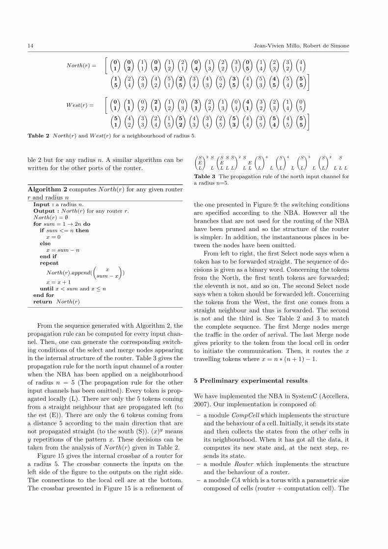
and West(r) are given by Table 2.
South(r) is the same as North(r) except that the
coordinates of the origins are the exact opposite of the
ones in North(r). Formally ∀(x
y
)∈ North(r) at posi-
tion i, ∃(−x−y
)∈ South(r) at position i. East(r) can
be computed from West(r) with the same transforma-
tion. Table 2 also presents West(r). Here we choose
to put the main coordinate (i.e. y) on top to enhance
the similitude with North(r). For the same reason, the
second value is −x instead of x.
The order of arrival of the tokens in West(r) inside
a stage is the exact opposite of North(r). For instance,(0
2
)is followed by
(1
1
)in the second and third position
of North(r) but
(1
1
)is followed by
(0
2
)in the second
and third position of West(r). This order inversion oc-
curs because the feeding rule of the routers starts with
the vertical ports at the expense of the horizontal ones.
Table 2 gives the status of the channel in input of
a router step by step. Therefore, the behaviour of the
routers is predictable and can be computed statically.
The following algorithm generates the sequence of Ta-
14 Jean-Vivien Millo, Robert de Simone
North(r) =
[ (01
) (02
) (11
) (03
) (12
) (21
) (04
) (13
) (22
) (31
)(05
) (14
) (23
) (32
) (41
)(
15
) (24
) (33
) (42
) (51
)(25
) (34
) (43
) (52
) (35
) (44
) (53
) (45
) (54
) (55
)]
West(r) =
[ (01
) (11
) (02
) (21
) (12
) (03
) (31
) (22
) (13
) (04
)(41
) (32
) (23
) (14
) (05
)(
51
) (42
) (33
) (24
) (15
)(52
) (43
) (34
) (25
) (53
) (44
) (35
) (54
) (45
) (55
)]Table 2 North(r) and West(r) for a neighbourhood of radius 5.
ble 2 but for any radius n. A similar algorithm can be
written for the other ports of the router.
Algorithm 2 computes North(r) for any given router
r and radius nInput : a radius n.Output : North(r) for any router r.North(r) = ∅for sum = 1→ 2n do
if sum <= n thenx = 0
elsex = sum− n
end ifrepeat
North(r).append(
(x
sum− x
))
x = x + 1until x < sum and x ≤ n
end forreturn North(r)
From the sequence generated with Algorithm 2, the
propagation rule can be computed for every input chan-
nel. Then, one can generate the corresponding switch-
ing conditions of the select and merge nodes appearing
in the internal structure of the router. Table 3 gives the
propagation rule for the north input channel of a router
when the NBA has been applied on a neighbourhood
of radius n = 5 (The propagation rule for the other
input channels has been omitted). Every token is prop-
agated locally (L). There are only the 5 tokens coming
from a straight neighbour that are propagated left (to
the est (E)). There are only the 6 tokens coming from
a distance 5 according to the main direction that are
not propagated straight (to the south (S)). (x)y means
y repetitions of the pattern x. These decisions can be
taken from the analysis of North(r) given in Table 2.
Figure 15 gives the internal crossbar of a router for
a radius 5. The crossbar connects the inputs on the
left side of the figure to the outputs on the right side.
The connections to the local cell are at the bottom.
The crossbar presented in Figure 15 is a refinement of
(SEL
)2 S
L
(SEL
S
L
S
L
)2 S
LEL
(S
L
)4
L
(S
L
)4
L
(S
L
)3
L
(S
L
)2
L
S
L L
Table 3 The propagation rule of the north input channel fora radius n=5.
the one presented in Figure 9: the switching conditions
are specified according to the NBA. However all the
branches that are not used for the routing of the NBA
have been pruned and so the structure of the router
is simpler. In addition, the instantaneous places in be-
tween the nodes have been omitted.
From left to right, the first Select node says when a
token has to be forwarded straight. The sequence of de-
cisions is given as a binary word. Concerning the tokens
from the North, the first tenth tokens are forwarded;
the eleventh is not, and so on. The second Select node
says when a token should be forwarded left. Concerning
the tokens from the West, the first one comes from a
straight neighbour and thus is forwarded. The second
is not and the third is. See Table 2 and 3 to match
the complete sequence. The first Merge nodes mergethe traffic in the order of arrival. The last Merge node
gives priority to the token from the local cell in order
to initiate the communication. Then, it routes the x
travelling tokens where x = n ∗ (n+ 1)− 1.
5 Preliminary experimental results
We have implemented the NBA in SystemC (Accellera,
2007). Our implementation is composed of:
– a module CompCell which implements the structure
and the behaviour of a cell. Initially, it sends its state
and then collects the states from the other cells in
its neighbourhood. When it has got all the data, it
computes its new state and, at the next step, re-
sends its state.
– a module Router which implements the structure
and the behaviour of a router.
– a module CA which is a torus with a parametric size
composed of cells (router + computation cell). The

Explicit routing schemes for implementation of CA on processor arrays 15
CO
PY
CO
PY
CO
PY
CO
PY
North
South
East
West
North
South
East
West
X
(110014014013012010)w
X
(1140140130120100)w
X
(110014014013012010)w
X
(1140140130120100)w (101021031041015)w
X
(1101021031019)w
X
(101021031041015)w
X
(1101021031019)w
X
0 1
0 1
0
1
0 1
0
1
0 1
0
1
0 1
0
1
0 1
0
1
0 1
(…)w
(…)w
(…)w
(…)w
(1324)w
2 1 4 3
COPY
0 1
0
1
0 1
0
1
(0(1)x)w
(0(1)x)w
(0(1)x)w
(0(1)x)w
Local Local
Fig. 15 The internal crossbar of the router with the switching conditions.
torus is both the structure of the cellular automaton
and the structure of the network on chip.
The propagation rule has been implemented by the
static patterns given in Table 3 and Figure 15. The ob-
served propagation time is conformed to the expected
one. This experiment consolidates the fact that a propa-
gation rule for a given application can be computed an-
alytically upfront as static decisions and then inserted
into the routers.
Stencil applications We have also extended the exper-
iments to the more general case of stencil applications
(Datta et al, 2008, 2009). Stencil applications are a class
of distributed applications where the new state of a cell
depends of the current state of some of its neighbours.
The map which says which neighbours are concerned
and which others are not is called a stencil. Stencil ap-
plications are massively used in scientific computation.
In our implementation, the stencil is given as an
odd square matrix of Boolean values where the middle
entry represents the concerned node. The other entries
represent its neighbourhood. The Boolean value says
whether the state of the corresponding neighbour is re-
quired or not. Every router is aware of the stencil and
routes the data with respect to their origin.
We ran many case studies where each stencil is char-
acterized by 1/ the number of neighbours it involves and
2/the Moore distance to the furthest neighbour. Table
4 relates the number of micro-steps required to route
all the tokens with respect to the different cases (The
number of neighbours in each stencil is noted N).
\ N = 4 8 16 24 32 48
||diff ||∞ ≤ 1 2 4 - - - -||diff ||∞ ≤ 2 4 4 12 16 - -||diff ||∞ ≤ 3 6 8 18 18 18 24
Table 4 Experimental results of routing duration for stencilapplications
Again, whatever is the shape of the stencil, the dy-
namic routing decisions can be replaced by static pat-
tern which are the same in every router. The next com-
putation step of the stencil application repeats the same
routing behaviour.
6 Conclusion
This paper focuses on the importance of the routing
activity in the design flow of parallel applications for
multicore platform. Network on chip based platforms
are subject to the same issues than usual network (con-
gestion, buffer overflow, arbitrary runtime routing de-
cisions). These problems limit the gain of performance
brought by the parallelization. On contrary to commu-
nication on the Internet, on-chip communications are
predictable and routing decisions can be taken in ad-
vance, thereby providing a mean to smooth the traffic.
We have presented the KRG model as one possible
way to include the routing information in the descrip-
tion of the application when modelled using MG.
Lastly, we have illustrated our approach with the
Neighbour Broadcasting Algorithm (NBA) which is a
routing algorithm for cellular automata based applica-

16 Jean-Vivien Millo, Robert de Simone
tions. The routing decisions have been computed from
the behavioural analysis of the algorithm in order to
configure the routers of the network on the targeted
platform.
The first future direction of this work is to automate
the extraction of the routing and scheduling informa-
tion from the co-simulation of the original model with
the refined model. In this paper, we have presented the
scheduling and routing information specific to the NBA.
We expect that the method can be automated for any
MG.
The second is to consider the case where the cellular
automata is decomposed in regular blocks of cells and
all the cells of the same block are allocated to the same
processing element. This configuration is more realis-
tic for the implementation of cellular automata on net-
work on chip based platforms or GPU based platforms.
However, the study we have conducted in this article
remains appropriate to FPGA and hardware based im-
plementation and it could be interesting to go further
in these directions also.
References
Accellera (2007) System c. Http://www.accellera.org/
downloads/ standards/ systemc
Benveniste A, Caspi P, Edwards SA, Halbwachs N,
Guernic PL, de Simone R (2003) The synchronous
languages 12 years later. Proceedings of the IEEE
91(1):64–83, DOI 10.1109/JPROC.2002.805826
Bilsen G, Engels M, Lauwereins R, Peperstraete J
(1995) Cyclo-static data flow. In: Acoustics, Speech,and Signal Processing, 1995. ICASSP-95., 1995 Inter-
national Conference on, vol 5, pp 3255 –3258 vol.5,
DOI 10.1109/ICASSP.1995.479579
Boucaron J, Coadou A, de Simone R (2010) Synthesis of
Embedded Software: Frameworks and Methodologies
for Correctness by Construction Software Design,
Shukla, Sandeep Kumar and Talpin, Jean-Pierre,
Springer, chap 2, pp 41–78
Boure O, Fates N, Chevrier V (2011) Robust-
ness of cellular automata in the light of asyn-
chronous information transmission. In: Proceed-
ings of the 10th international conference on
Unconventional computation, Springer-Verlag,
Berlin, Heidelberg, UC’11, pp 52–63, URL
http://dl.acm.org/citation.cfm?id=2022023.2022036
Chaudhuri PP, Chowdhury DR, Nandi S, Chattopad-
hyay S (1997) Additive Cellular Automata. Willey-
IEEE Computer Society Press
Coadou A (2010) Reseaux de processus flots de donnees
avec routage pour la modelisation de systemes em-
barques. PhD thesis, University of Nice Sophia An-
tipolis
Cohen A, Duranton M, Eisenbeis C, Pagetti C, Plateau
F, Pouzet M (2006) N-synchronous kahn networks.
In: POPL 2006 Proceedings, pp 180–193
Commoner F, Holt AW, Even S, Pnueli A (1971)
Marked directed graph. Journal of Computer and
System Sciences 5:511–523
Datta K, Murphy M, Volkov V, Williams S,
Carter J, Oliker L, Patterson D, Shalf J, Yelick
K (2008) Stencil computation optimization and
auto-tuning on state-of-the-art multicore architec-
tures. In: Proceedings of the 2008 ACM/IEEE
conference on Supercomputing, IEEE Press, Pis-
cataway, NJ, USA, SC ’08, pp 4:1–4:12, URL
http://dl.acm.org/citation.cfm?id=1413370.1413375
Datta K, Williams S, Volkov V, Carter J, Oliker L, Shalf
J, Yelick K (2009) Auto-tuning the 27-point stencil
for multicore. In: In Proc. iWAPT2009: The Fourth
International Workshop on Automatic Performance
Tuning, p 17
Davare A, Densmore D, Meyerowitz T, Pinto A,
Sangiovanni-Vincentelli A, Yang G, Zeng H, Zhu
Q (2007) A next-generation design framework for
platform-based design. In: DVCon 2007, p 8, URL
http://chess.eecs.berkeley.edu/pubs/228.html
Dennunzio A (2012) From one-dimensional to two-
dimensional cellular automata. Fundam Inform
115(1):87–105
Eker J, Janneck J, Lee E, Liu J, Liu X, Ludvig
J, Neuendorffer S, Sachs S, Xiong Y (2003) Tam-
ing heterogeneity - the ptolemy approach. Pro-
ceedings of the IEEE 91(1):127 – 144, DOI
10.1109/JPROC.2002.805829
Ferrari A, Sangiovanni-Vincentelli A (1999) System
design: traditional concepts and new paradigms.
In: Computer Design, 1999. (ICCD ’99) In-
ternational Conference on, pp 2 –12, DOI
10.1109/ICCD.1999.808256
Gardner M (1970) The fantastic combinations of john
conway’s new solitaire game “life”. Scientific Ameri-
can 223:120–123
Glitia C, DeAntoni J, Mallet F, Millo JV, Boulet
P, Gamatie A (2012) Progressive and explicit
refinement of scheduling for multidimensional
data-flow applications using uml marte. Design
Automation for Embedded Systems 16:137–169,
URL http://dx.doi.org/10.1007/s10617-012-9093-y,
10.1007/s10617-012-9093-y
Grandpierre T, Lavarenne C, Sorel Y (1999) Opti-
mized rapid prototyping for real-time embedded het-
erogeneous multiprocessors. In: Proceedings of 7th
International Workshop on Hardware/Software Co-

Explicit routing schemes for implementation of CA on processor arrays 17
Design, CODES’99, Rome, Italy
Halbach M, Hoffmann R (2004) Implementing
cellular automata in fpga logic. In: Parallel
and Distributed Processing Symposium, 2004.
Proceedings. 18th International, p 258, DOI
10.1109/IPDPS.2004.1303324
Herrera F, Villar E (2011) A framework for the gener-
ation from uml/marte models of ipxact hw platform
descriptions for multi-level performance estimation.
In: FDL, IEEE, pp 1–8
Jantsch A (2008) Models of computation for distributed
embedded systems. In: Zurawski R (ed) Networked
Embedded Systems, CRC Press/Taylor & Francis,
chap 3, pp –
Kalray (2012) Mppa manycore.
Http://www.kalray.eu/products/mppa-manycore
Kari J (2005) Theory of cellular automata: A survey.
Theoretical Computer Science 334(1-3):3 – 33, DOI
10.1016/j.tcs.2004.11.021
Kobori T, Maruyama T, Hoshino T (2001) A cel-
lular automata system with fpga. In: Proceedings
of the the 9th Annual IEEE Symposium on Field-
Programmable Custom Computing Machines, IEEE
Computer Society, Washington, DC, USA, FCCM
’01, pp 120–129, DOI 10.1109/FCCM.2001.2, URL
http://dx.doi.org/10.1109/FCCM.2001.2
Marouf M, Sorel Y (2011) Scheduling non-preemptive
hard real-time tasks with strict periods. In: Pro-
ceedings of 16th IEEE International Conference on
Emerging Technologies and Factory Automation,
ETFA’11, Toulouse, France, pp 1–8
Melpignano D, Benini L, Flamand E, Jego B, Lepley
T, Haugou G, Clermidy F, Dutoit D (2012) Platform
2012, a many-core computing accelerator for embed-
ded socs: performance evaluation of visual analytics
applications. In: DAC 2012, pp 1137–1142
de Micheli G, Benini L (2006) Networks on chips. Mor-
gan Kauffmann (Elsevier)
Millo JV, de Simone R (2012a) Periodic schedul-
ing of marked graphs using balanced binary words.
Theoretical Computer Science 458:113-130, DOI
10.1016/j.tcs.2012.08.012
Millo JV, de Simone R (2012b) Refining cellular au-
tomata with routing constraints. In: Formenti E (ed)
Automata & JAC (Exploratory track), vol 2, p 15
Parks T (1995) Bounded scheduling of process net-
works. PhD thesis, EECS, Department, University
of California, Berkeley CA 94720, technical Report
UCB/ERL-95-105
Rybacki S, Himmelspach J, Uhrmacher AM (2009)
Experiments with single core, multi-core, and gpu
based computation of cellular automata. In: Pro-
ceedings of the 2009 First International Confer-
ence on Advances in System Simulation, IEEE
Computer Society, Washington, DC, USA, SIMUL
’09, pp 62–67, DOI 10.1109/SIMUL.2009.36, URL
http://dx.doi.org/10.1109/SIMUL.2009.36
Sangiovanni-Vincentelli AL, Passerone R (2012)
Platform-based Design. Springer-Verlag New York
Inc
Sriram S, Bhattacharyya SS (2009) Embedded mul-
tiprocessors, Scheduling and Synchronization. CRC
Press
Zaloudek L, Sekanina L, Simek V (2009) Gpu accel-
erators for evolvable cellular automata. In: Future
Computing, Service Computation, Cognitive, Adap-
tive, Content, Patterns, 2009. COMPUTATION-
WORLD ’09. Computation World:, pp 533 –537,
DOI 10.1109/ComputationWorld.2009.49


