Expert System Architecture for Retaining Wall...
12
TRANSPORTATION RESEA RCH RECORD 1187 9 Expert System Architecture for Retaining Wall Design T. M. ADAMS, C. HENDRICKSON, AND P. CHRISTIANO The design of emergency repairs and the growing inventory of failing or newly repaired retaining walls present a considerable practical problem. For repair work, time and budget con- straints are pressing. Available expertise is limited and often dispersed among numerous individuals, so extensive consul- tation is often required. If an intelligent aid were available, engineers and managers would be able to make better and faster decisions. Described in this paper are the architecture and several modules of an expert system aid for retaining wall rehabilitation design. Such a system could be used by an engineer who is called upon to evaluate a retaining wall failure, conduct a survey of the condition of existing walls, or design a rehabilitation or new construction strategy for a wall. Issues addressed include appropriate problem paradigm models, al- ternative solution strategies, and reasoning with uncertainty. Preliminary design and conceptual cost estimation are fundamental engineering activities in the provision of newly constructed facilities or in the repair and rehabili- tation of existing infrastructure. Initial decisions at the conceptual or planning stage form the basis for detailed engineering design and construction agreements. Poor de- cisions can cause delays, excessive costs, or, if mistakes are not recognized, unsafe and inadequate facilities. Given the importance of this activity to the nation's infrastructure, improvement of the practice of preliminary design and conceptual cost estimation is of great value. Retaining walls provide an excellent example of the problems and processes associated with preliminary engi- neering design and cost estimation. These walls are ubiq- uitous in the United States and perform as necessary components of a variety of infrastructure facilities includ- ing roads, bridges, buildings, drainage systems, and so on. In essence, retaining walls act as "infrastructure compo- nents" for infrastructure systems. Repairing, replacing, and rehabilitating the large number of existing walls are com- mon engineering problems involving consideration of nu- merous options, such as simple concrete crack repairs, replacement of reinforcing steel, or insertion of tiebacks. The option of fully replacing damaged walls also raises a variety of alternatives for overall design of new walls and problems of stabilizing existing soil conditions during con- struction. Assessing the technical feasibility, cost, and over- Department of Civil Engineering, Carnegie-Mellon University, Pittsburgh, PA 15213. all desirability of different options requires considerable judgment and expertise by the engineer or manager. Most designers of retaining walls are skillful at deter- mining a nearly optimal configuration of a particular design once the decision has been made to construct a wall of a particular type. If a reinforced concrete cantilever wall has been selected, for example, standard design procedures lead to 'the choice of concrete thickness and amount of reinforcing of the stem, as well as the dimensions and reinforcing of the toe, heel, and key. An individual engi- neer may find it much more difficult, however, to deter- mine whether a cantilever wall is the best choice among those available. In the last few decades, a smaller fraction of traditional cast-in-place-concrete gravity and cantilever walls has been built because of a rising popularity of earthwork reinforcement and prefabricated modular sys- tems (1). In many situations, specialty proprietary systems can be constructed at 30 to 50 percent less cost and construction time than for conventional cast-in-place walls (R. M. Leary and G. L. Klinedinst, unpublished data). The issue becomes even more important for walls having heights greater than 10 ft as the relevant number of design alternatives increases. As a result, considering numerous alternative wall systems is required for acceptable engi- neering practice. The task of determining feasible designs for prescribed conditions is not easy, because many different retaining systems are available. However, project constraints and site conditions often dictate the type of retaining structure that should be considered. Some wall systems may be eliminated because of unavailability of materials, neces- sary service life, or environmental and aesthetic require- ments. Special loading requirements, anticipated settle- ments, and adaptability to field changes must also be considered before a wall system is chosen. To make an intelligent decision requires familiarity with the available alternatives. Furthermore, a comparison of complete wall designs is often necessary before selection of one that will perform satisfactorily and can be constructed at the lowest overall cost. To help state highway departments choose and contract alternative retaining wall systems, some guidelines have been established by the FHW A. However, the recent focus of state highway projects has shifted from new construction to reconstruction and widening of existing facilities (R. M.
Transcript of Expert System Architecture for Retaining Wall...

TRANSPORTATION RESEARCH RECORD 1187 9
Expert System Architecture for Retaining Wall Design
T. M. ADAMS, C. HENDRICKSON, AND P. CHRISTIANO
The design of emergency repairs and the growing inventory of failing or newly repaired retaining walls present a considerable practical problem. For repair work, time and budget constraints are pressing. Available expertise is limited and often dispersed among numerous individuals, so extensive consultation is often required. If an intelligent aid were available, engineers and managers would be able to make better and faster decisions. Described in this paper are the architecture and several modules of an expert system aid for retaining wall rehabilitation design. Such a system could be used by an engineer who is called upon to evaluate a retaining wall failure, conduct a survey of the condition of existing walls, or design a rehabilitation or new construction strategy for a wall. Issues addressed include appropriate problem paradigm models, alternative solution strategies, and reasoning with uncertainty.
Preliminary design and conceptual cost estimation are fundamental engineering activities in the provision of newly constructed facilities or in the repair and rehabilitation of existing infrastructure. Initial decisions at the conceptual or planning stage form the basis for detailed engineering design and construction agreements. Poor decisions can cause delays, excessive costs, or, if mistakes are not recognized, unsafe and inadequate facilities . Given the importance of this activity to the nation's infrastructure, improvement of the practice of preliminary design and conceptual cost estimation is of great value.
Retaining walls provide an excellent example of the problems and processes associated with preliminary engineering design and cost estimation. These walls are ubiquitous in the United States and perform as necessary components of a variety of infrastructure facilities including roads, bridges, buildings, drainage systems, and so on. In essence, retaining walls act as "infrastructure components" for infrastructure systems. Repairing, replacing, and rehabilitating the large number of existing walls are common engineering problems involving consideration of numerous options, such as simple concrete crack repairs, replacement of reinforcing steel, or insertion of tiebacks. The option of fully replacing damaged walls also raises a variety of alternatives for overall design of new walls and problems of stabilizing existing soil conditions during construction. Assessing the technical feasibility, cost, and over-
Department of Civil Engineering, Carnegie-Mellon University, Pittsburgh, PA 15213.
all desirability of different options requires considerable judgment and expertise by the engineer or manager.
Most designers of retaining walls are skillful at determining a nearly optimal configuration of a particular design once the decision has been made to construct a wall of a particular type. If a reinforced concrete cantilever wall has been selected, for example, standard design procedures lead to 'the choice of concrete thickness and amount of reinforcing of the stem, as well as the dimensions and reinforcing of the toe, heel, and key. An individual engineer may find it much more difficult, however, to determine whether a cantilever wall is the best choice among those available. In the last few decades, a smaller fraction of traditional cast-in-place-concrete gravity and cantilever walls has been built because of a rising popularity of earthwork reinforcement and prefabricated modular systems (1). In many situations, specialty proprietary systems can be constructed at 30 to 50 percent less cost and construction time than for conventional cast-in-place walls (R. M. Leary and G. L. Klinedinst, unpublished data). The issue becomes even more important for walls having heights greater than 10 ft as the relevant number of design alternatives increases. As a result, considering numerous alternative wall systems is required for acceptable engineering practice.
The task of determining feasible designs for prescribed conditions is not easy, because many different retaining systems are available. However, project constraints and site conditions often dictate the type of retaining structure that should be considered. Some wall systems may be eliminated because of unavailability of materials, necessary service life, or environmental and aesthetic requirements. Special loading requirements, anticipated settlements, and adaptability to field changes must also be considered before a wall system is chosen. To make an intelligent decision requires familiarity with the available alternatives. Furthermore, a comparison of complete wall designs is often necessary before selection of one that will perform satisfactorily and can be constructed at the lowest overall cost.
To help state highway departments choose and contract alternative retaining wall systems, some guidelines have been established by the FHW A. However, the recent focus of state highway projects has shifted from new construction to reconstruction and widening of existing facilities (R. M.

10
Leary and G. L. Klinedinst, unpublished data). Thus the problems associated with economically and effectively dealing with old and failing retaining walls are becoming relevant. As another example, the city of Pittsburgh has hundreds of walls that were built at the turn of the century, many of which need immediate rehabilitation or replacement (2).
Knowledge-based expert systems (KBES} provide a practical means to incorporate experts' heuristics, rules of thumb, judgments, empirical associations, and historical information into a computer program that can assist and guide practitioners. In contrast to algorithmic processes, KBES need not have all contingencies preprogrammed and anticipated. Although these systems have already been applied in a variety of applications (3. 4), the use of expert systems technology in infrastructure rehabilitation has not been extensively investigated.
In this paper, the expert systems architecture for a retaining wall design assistant is described. A prototype system called RETAIN has been implemented in C language and the OPS5 expert system environment. The RETAIN project focuses on categorizing and organizing knowledge about failures, rehabilitation, and replacement alternatives of either vertical or battered earth-retaining walls. The problem is broken into two general models: retaining wall failure diagnosis and rehabilitation strategy design. An understanding of the domain knowledge and problem formulation is coupled with expert systems problem paradigm models and problem-solving strategies to create an intelligent aid for solving retaining wall problems.
BACKGROUND
Retaining Walls
Although numerous authors discuss the design of various types of new earth-retaining structures (5-9}, little information is available on the rehabilitation of existing walls. Besides reliability and useful life expectancy, the factors that dictate the rational design of retaining walls are the available materials, magnitude, and type of forces acting on the wall, space required, soil characteristics, appearance, and, finally, cost. Yet, like most structures, retaining walls are designed largely from the designer's experience, which is often limited to a few types of walls. Although some might argue that the choice of design becomes fairly obvious once loads and geometric conditions have been established, one usually finds that retaining wall alternatives embrace a great variety of types, geometries, materials, and construction methods. As will be described, 1t:iaiuiu~ waiis ~cl.ii be; divid~d itttv fvu.r rr..uiu ty·p~:;
gravity, cantilever, anchored, and reinforced backfilldepending on how they retain earth and resist external loads.
Gravity Walls
Gravity walls provide stability against sliding and overturning by their weight alo~e or by their ~eight in com-
TRANSPORTAIJON RESEARCH RECORD 1187
bination with soil weight. Although such walls may be classified as either rigid or flexible, all are free to displace laterally, thereby mobilizing active earth pressures. Rigid gravity walls-which include cast-in-place mass concrete walls and masonry set block, brick, or rubble walls-have little tolerance to settlement. In addition, through-wall drainage is necessary to relieve hydrostatic pressure caused by saturated backfill soil. The components of flexible walls such as crib, bin, gabion, drystone rubble, and interlocking modular walls are not rigidly connected; this gives them the inherent advantages of positive drainage through the wall and some tolerance to nonuniform settlement. Crib walls are built by forming interconnected boxes from timber or concrete stringer-and-tie members. Examples of precast-concrete crib wall systems are Dura-Crib™, DuraHold™, Concrib™, and Criblock™. Bin walls are made of flexible sheeting such as corrugated aluminum or galvanized steel; examples include Terra-Wair" and Armco™. Gabion walls are constructed from building blocks of metallic wire baskets filled with broken stone. Examples of interlocking precast-concrete units that may be dry set to form flexible gravity walls are PISA II'", Doublewal'", and Evergreen'". With some modular wall systems, the components themselves are backfilled as the wall is constructed, to provide added wall mass to resist lateral pressure. Typically the manufacturers of modular walls provide some guidelines for the design and construction of their system.
Cantilever Walls
Cantilever walls resist lateral forces through cantilever bending of the wall stem. Such walls include reinforcedconcrete, soldier piles and lagging, and permanently anchored cylinder pile walls. Designing a conventional reinforced-concrete cantilever retaining wall involves determining the base size and the stem position on the base, as well as the thickness and reinforcing of the stem, toe, and heel. Design charts (10) based on the strength design method simplify the iterative process of designing concrete cantilever retaining walls. A minimum cost design method (1 J} may be used to proportion a cantilever retaining wall, satisfy design criteria, and minimize cost of concrete and steel. Design aids (12) are available for determining how bearing pressure varies with changes in footing width. To avoid diagonal tension cracks, the best corner reinforcing details depend on the toe-length-to-stem-thickness ratio of the wall (13). Soldier piles and timber liigging walls (also called Berlin walls) are constructed by first driving wide flange steel sections 6 to I 0 ft apart along the wall line. As excavation in front of the wall proceeds, timber lagging is inserted between the piles. Soldier pile walls are not suitable for retaining soft clays or running soils such as loose sand, because portions of the wall must be left unsupported while lagging is installed. A permanently anchored cylinder pile wall (14) consists of prestressing steel strands in concrete cylinder piles anchored in rock. The steel tendons are bowed to pull the top of the caisson back toward the soil and thus reduce wall deflections.
Adams et al.
Anchored Walls
Anchored walls support horizontal loads with tension members that are connected to the wall facing. These walls are constructed from the top down; this is an advantage because the slope is always supported and no preexcavation is required. Moreover, the wall's capacity may be increased, after the wall is completed, by installing additional anchors. One type of tieback wall (14) is an extension of the soldier pile and lagging wall, in that a row of high-strength steel tiebacks is placed into the soil behind the wall after each 5- to LO-ft lift is excavated. A curtain wall (8) consists ofa "curtain" of reinforced concrete about 8 to 12 in. thick constructed from the top down as the slope is cut in benches. The wall is tied back with anchors at each bench level. There is no universal type of tieback anchor. Various soil strata require different anchorage systems and installation equipment: rock anchors if competent rock is near; augered earth anchors in cohesive soils; and small-diameter cased earth anchors in predominantly granular soil. Because tiebacks are soil dependent, if soil conditions are not determined accurately, problems such as pullout or inadequate development of frictional resistance may occur (15). Deadman anchors are short blocks, continuous beams, or plates that are placed in the excavated embankment behind the wall and then linked to face panels by reinforcing bars. The wall is then backfilled and compacted after the deadman anchors are positioned and connected. Deadman anchors derive their resistance from passive earth pressure. They can be implanted behind the wall near the ground surface, at depth, or in layers. Geotech TM is an example of a deadman retaining wall system. In the past, highway agencies have avoided building anchored walls out of concern that corrosion of the anchor tendons may lead to failures. Cheney (16) combined design criteria from several geotechnical contractors in a manual that contains basic anchoring concepts and guidelines for evaluating the feasibility of anchors in specific situations.
Reinforced Backfill Walls
Reinforced backfill walls include Reinforced EarthT", Retained EarthT", Georgia Stabilized Earth, Mechanically Stabilized EmbankmentsT", Hilfiker Welded Wire Walls, and walls constructed with geotextiles or geogrids that provide tensile reinforcement within the backfill material. Reinforced backfill is a construction material composed of soil fill strengthened and mechanically stabilized by reinforcing that interacts frictionally with the soil. Reinforced backfill walls are constructed of horizontal reinforcement vertically spaced between layers of compacted backfill (17-19). The beneficial effects depend on a combination of the reinforcement's tensile strength and shear bond with the soil backfill. The reinforcing acts to supplement the tensile strength of the backfill, much the same as the steel bars in reinforced concrete. Various forms of reinforcing are used, such as steel strips, wire mesh strips, wire mesh fabric, geotextile fabric, and polymer grid. Rein-
11
forced backfill walls impose nearly uniform pressure distributions on foundation soils, thus creating uniform settlement. Reinforced backfill walls are a good choice if deep, poor foundation material exists at the site. In steelreinforced systems, the reinforcing itself must be galvanized or epoxy coated to protect from corrosion (20, 21). The design assumption for these walls is that the reinforced material acts as a block, and the block acts as a gravity wall.
Expert Systems in Geotechnical and Transportation Engineering
Two reports (3, 4) summarize the current state of KBES in geotechnical and transportation engineering. Most of the systems discussed in this section are described in those reports.
WADI (22) and RETW ALL (23) are two prototype systems that address aspects of retaining wall design that are closely related to the rehabilitation problem. WADI diagnoses concrete retaining wall failures in four categories: footing, drainage, or construction problems and problems associated with weak bearing soil. RETW ALL is a selection system containing heuristics for selecting the appropriate types of retaining structure from a number of options. Neither of these systems is complete for practical application.
Expert system aids are of particular interest to transportation engineers, who generally do not have the time, training, or experience to handle maintenance and rehabilitation problems. Considerable work has been undertaken on highway pavement maintenance and rehabilitation problems (24). Pavement problems are the focus of systems such as ROSE (25) and PRESERVER (26). PARADIGM (27) is an integrated set of expert systems for the analysis and design of pavement rehabilitation strategies. Two component systems of PARADIGM and SCEPTRE and OVERDRIVE. SCEPTRE evaluates pavement surface conditions to identify workable rehabilitation and maintenance strategies. OVERDRIVE provides design guidance for asphalt concrete overlay rehabilitation strategies. Another component of PARADIGM optimizes a rehabilitation planning network according to construction budget constraints.
Several systems in other domains include ideas and modules that can be applied to the retaining wall rehabilitation problem. PROSPECTOR (28) is a mineral exploration interpretation system designed to handle problems in ore deposit identification, regional resource evaluation, and drilling site selection. In PROSPECTOR, ore deposit models are encoded as inference networks of connections or relations between field evidence and geological hypothesis. The term "model" refers to the body of knowledge about a particular ore deposit that is encoded into the system. Each ore deposit model is designed to emulate the reasoning process of an experienced exploration geologist who is assessing a given prospect site or region for the likelihood that it contains a deposit of the ore type represented by the model. In PROSPECTOR, both evidence
12
and hypotheses are referred to as assertions, and models are referred to as inference networks of assertions. PROSPECTOR accommodates uncertainty in both evidence and hypotheses using an approximate form of Bayesian probability. Inference networks of assertions along with Bayesian decision theory have been used to develop a consultant system for physical property prediction of chemicals (29). The same approach is described here to diagnose failing retaining walls.
OVERVIEW OF RETAIN
The expert system RETAIN, described herein, is designed to function as an aid to designers whose personal experience with failure diagnosis, retaining wall design, and cost ":Stimation is limited to a narrow range of circumstances md design alternatives. Certainly, this expert system is not to be viewed as a substitute for an experienced knowledgeable practitioner. Instead, it represents an attempt to frame the stated problem so that gaps in knowledge and experience can be identified but permits its continual evolution as practitioners contribute new knowledge. Although the inevitable limitations of expert systems often are a source of frustration to users, the potential of these systems to identify critical analysis and design alternatives should not be underestimated. Familiarity with these alternatives is most often the weakest component in the repertoire of even the most experienced individual.
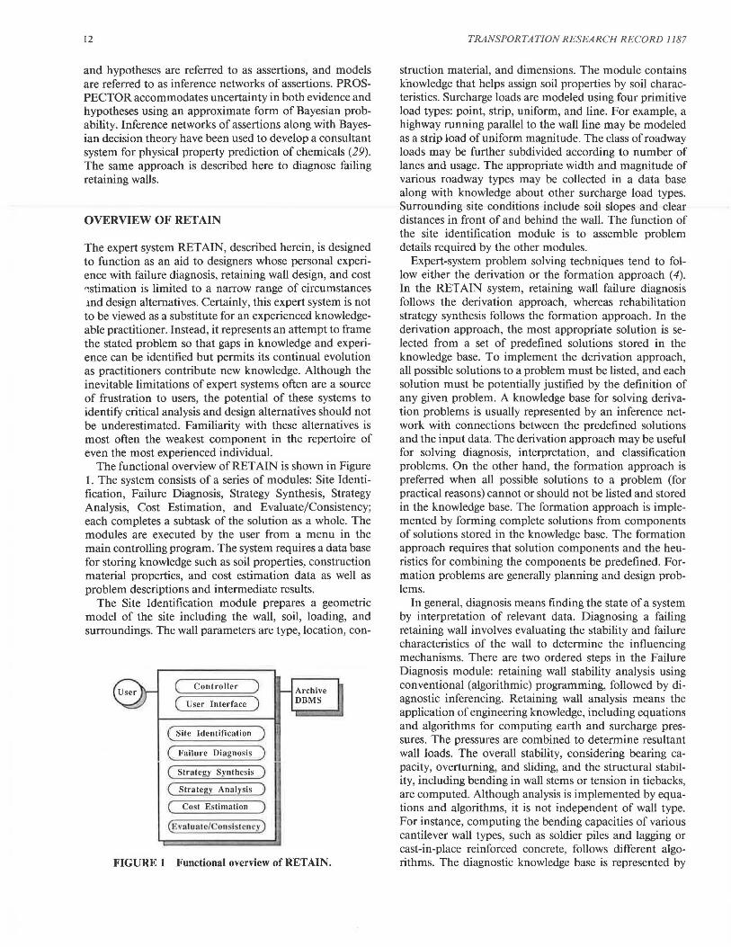
The functional overview of RETAIN is shown in Figure 1. The system consists of a series of modules: Site Identification, Failure Diagnosis, Strategy Synthesis, Strategy Analysis, Cost Estimation, and Evaluate/Consistency; each completes a subtask of the solution as a whole. The modules are executed by the user from a menu in the main controlling program. The system requires a data base for storing knowledge such as soil properties, construction material properties, and cost estimation data as well as problem descriptions and intermediate results.
The Site Identification module prepares a geometric model of the site including the wall, soil, loading, and surroundings. The wall parameters are type, location, con-
( Controller )
( User Interface )
( Site Identifica tion )
( Failure Diagnosis )
( Strategy Synthesis )
( Strategy Analysis )
( Cost Estimation )
(E,.n lunt c/ on lstcncy )
Archive DBMS
FIGURE 1 Functional overview of RETAIN.
TRANSPORTATION RESEARCH RECORD 1187
struction material, and dimensions. The module contains knowledge that helps assign soil properties by soil characteristics. Surcharge loads are modeled using four primitive load types: point, strip, uniform, and line. For example, a highway running parallel to the wall line may be modeled as a strip load of uniform magnitude. The class of roadway loads may be further subdivided according to number of lanes and usage. The appropriate width and magnitude of various roadway types may be collected in a data base along with knowledge about other surcharge load types. Surrounding site conditions include soil slopes and clear distances in front of and behind the wall. The function of the site identification module is to assemble problem details required by the other modules.
Expert-system problem solving techniques tend to follow either the derivation or the formation approach ( 4). In the RETAIN system, retaining wall failure diagnosis follows the derivation approach, whereas rehabilitation strategy synthesis follows the formation approach. In the derivation approach, the most appropriate solution is selected from a set of predefined solutions stored in the knowledge base. To implement the derivation approach, all possible solutions to a problem must be listed, and each solution must be potentially justified by the definition of any given problem. A knowledge base for solving derivation problems is usually represented by an inference network with connections between the predefined solutions and the input data. The derivation approach may be useful for solving diagnosis, interpretation, and classification problems. On the other hand, the formation approach is preferred when all possible solutions to a problem (for practical reasons) cannot or should not be listed and stored in the knowledge base. The formation approach is implemented by forming complete solutions from components of solutions stored in the knowledge base. The formation approach requires that solution components and the heuristics for combining the components be predefined. Formation problems are generally planning and design problems.
In general, diagnosis means finding the state of a system by interpretation of relevant data. Diagnosing a failing retaining wall involves evaluating the stability and failure characteristics of the wall to determine the influencing mechanisms. There are two ordered steps in the Failure Diagnosis module: retaining wall stability analysis using conventional (algorithmic) programming, followed by diagnostic inferencing. Retaining wall analysis means the application of engineering knowledge, including equations and algorithms for computing earth and surcharge pressures. The pressures are combined to determine resultant wall loads. The overall stability, considering bearing capacity, overturning, and sliding, and the structural stability, including bending in wall stems or tension in tiebacks, are computed. Although analysis is implemented by equations and algorithms, it is not independent of wall type. For instance, computing the bending capacities of various cantilever wall types, such as soldier piles and lagging or cast-in-place reinforced concrete, follows different algorithms. The diagnostic knowledge base is represented by

Adams et al.
inference networks similar to those in the PROSPECTOR system (28), with logical and plausible relations to reason with uncertainty. Diagnostic inferencing is handled by DIGR (30), an OPS diagnostic inference engine. The DIGR kernel and an example of a retaining wall diagnostic network model are discussed in the following section.
The synthesis, analysis, and evaluation of rehabilitation strategies constitute an engineering design problem. Solving such a problem involves a number of distinctive phases, beginning with the definition of a particular problem and ending with the selection of an optimum solution. Commonly the three main phases are as follows:
1. Synthesis of preliminary design. The conceptual aspects of engineering design are embodied in this phase. The result of synthesis is a set of preliminary design alternatives that satisfies the end product specifications. The specifications for retaining wall rehabilitation designs are the wall type to be rehabilitated, failure mechanisms to be corrected, limitations of the soil, and constraints dictated by the site. Synthesis deals with the formation of design alternatives by searching and checking subsystems. In the RETAIN system, this task is accomplished by the Strategy Synthesis module.
2. Analysis. During this phase preliminary design alternatives are studied using mathematical and other analysis procedures. The purpose of this phase is to refine the preliminary designs in an effort to determine their response in the intended environment. Important aspects of this phase are selection of the proper analysis procedure, correct use of these procedures, and appropriate interpretation of the results. The Strategy Analysis module sizes the components of each synthesized rehabilitation strategy. Preliminary designs include wall and footing dimensions, drainage characteristics, approximate spacing of tiebacks and anchors, amount of excavation, and so on.
3. Evaluation and optimization. This phase, composed of the Cost Estimation and Evaluate/Consistency modules, involves evaluation of the analyzed design alternatives. The Cost Estimate module prepares a preliminary cost estimate for each design. Cost estimation may be handled by production rules, with algorithmic computational functions, which query a data base for specific unit cost factors (31). In the Evaluate/Consistency module, all feasible rehabilitation strategies are ranked by how well they meet project objectives such as cost, availability of materials, minimizing construction time, and minimizing disruptions to traffic and other structures. Output from this phase is the overall evaluation and ranking of feasible rehabilitation alternatives.
The RETAIN system is represented by rules in an OPS language (32, 33) production system. A rule-based production system architecture was chosen because it is widely available and easily transported. The OPS languages provide flexibility for storing domain-specific knowledge and for alternative inference engine strategies for problem solving.
13
The knowledge base of the expert system is being obtained from three sources. First, literature sources, which include technical journals, textbooks, manuals, public and commercial documents and reports, are used. Although the proliferation of retaining wall alternatives currently available has created a greatly enlarged set of design options (1), the issues pertaining to retaining wall rehabilitation are rarely addressed in the literature, except for a few isolated case studies. Useful published sources are case studies and technical documents that describe infrastructure rehabilitation techniques such as underpinning and anchoring (16, 34). Knowledge obtained from literature sources is being used in soil property assignment, wall stability analysis, and rehabilitation strategy analysis. A second source of domain-specific knowledge is a panel of experts who will help develop retaining wall diagnostic networks and provide information such as applicable heuristics for cost estimation and conditions under which particular rehabilitation techniques are feasible. Knowledge from the third source, testing, will be incorporated during the final stages of development when a number of case tests are undertaken for validation and further development. Results of testing will be incorporated into the system as appropriate.
USE OF INFERENCE NETWORKS TO DIAGNOSE RETAINING WALL FAILURES
In this section, an example inference network for retaining wall failure diagnosis is described. The network is a form of the inference network of assertions used by the PROSPECTOR (28) system to identify ore deposits. The DIGR (30) inference engine is used to traverse the network and apply logical and plausible relations so it can reason with uncertainty.
Network Model
An inference network can be depicted in hierarchical form, as shown in Figure 2, in which the terminal or leaf nodes correspond to evidence and the intermediate nodes represent conclusions or hypotheses. All nodes are referred to as assertions. The certainty of the top assertion (Forward Tilting Failure) indicates how well the available evidence matches the network model. The certainty of the top assertion is determined by the second-level assertions (Forward Tilting Wall and Forward Tilting Failure Type), which in turn are determined by the third-level assertions, and so forth. The search is finished when assertions are reached that may be established from evidence assertions. This tree traversal, executed as backward chaining, is depth-first with a left-to-right sequence.
To illustrate inference network modeling, first consider the failure modes shown in Figure 3. These failures are common for cast-in-place concrete walls, such as reinforced-concrete cantilever, buttress, and counterfort walls, and mass gravity walls. The primary evidence for each of the failure types is forward tilting of the wall. However,

14
FIELD P~0.25
Forward Tilting Wall C(EtE·)~5
RULE P~0 . 3
Toe Seltlemenl
LN~0.001
LS~IOO
COMP Pa0.25
Coin prcssl\•e IJ"'c C(l;lF.') ><4
RULE P~0.9
Overturning Failure
LN~0. 1
LS~lOO
Excessive Moment C(EIE')~·3
FIGURE 2 Example of inference network of assertions for wall diagnosis.
Toe Seltlcmcnt Overturning Failure
Benring Capacity Failure
FIGURE 3 Forward tilting failures of cast-in-place concrete walls.
the cause of tilting is different in each case. Toe settlement may have occurred if the bearing soil is compressive. Compressive soils include soft clays and loose sands or gravels. Overturning failure occurs when the earth pressure and surcharge pressures cause an overturning moment about the wall toe that is greater than the resisting moment. If the foundation soil is completely rigid, the wall will rotate about its toe. Bearing capacity failure occurs when the bearing pressure is higher than the bearing capacity of the foundation soil. A bearing capacity failure causes foundation soil to be pushed from beneath the wall toe, causing a bulge in front of the wall.
The inference network in Figure 2 models the failure --- - ..J __ -1- ----- .: __ r..: _____ ") r. ...... _ ~.:-·~- ........ .:,...J ...... _ ............ 4-1.. ................. 4- ......... -1,. lUUU~.:l ;:)lJUVVU 111 .1 JOUl\.i J . .1 Ul 51vv.u \.i\'.lU\.d.J\.;\,.I' LJ..l\.; UVLVVUJ.n.
is used to assess the likelihood of each failure mode. There are two types of evidence nodes: COMP and FIELD. COMP nodes represent evidence that may be gathered from the problem description or from retaining wall stability analysis. FIELD nodes represent evidence supplied by the user after field inspection. There are three types of hypothesis node: AND, OR, and RULE. AND and OR
TRANSPORTATION RESEARCH RECORD 1187
nodes use logical relations to combine subnode evidence, whereas RULE nodes use plausible relations.
Reasoning with Uncertainty
When a retaining wall is diagnosed, some uncertainty exists whether evidence and hypotheses are true or false. The certainty measure C(E / E') of an evidence node may be described as the certainty of the node evidence E given the available evidence E'. Certainty measures are defined on a scale of 5 (certainly true) to -5 (certainly false). Initially the certainty of each node in a network is unknown (certainty = 0). As evidence is gathered by using logical and plausible relations some hypotheses may be definitely established, whereas others may become only more or less likely or even excluded entirely. Verbal descriptions of numerical certainties are given in Table 1.
In the retaining wall diagnosis network, a set of evidence certainty measures is assigned by the user and the system for each wall diagnosed. Evidence certainty measures are provided by the user at FIELD nodes. For example, if the field evidence shows that a wall is tilting forward, the input certainty at the FIELD node Forward Tilting Wall is 5 (see Figure 2). In some cases the user may not have enough information to determine if evidence is present or absent. An example of this situation might occur at node Soil Bulge. Because of soil erosion, vegetation growth, or construction activity in front of the wall, the user may not be able to determine if the Soil Bulge evidence is present or absent. In this case, the user may indicate that there is "no information," and the evidence certainty measure remains equal to zero (see Figure 2). At COMP nodes, evidence certainty measures are assigned by the system rrom the problem description. For example, the evidence certainty at node Compressive Base need not be provided by the user, because it may be inferred from the wall's bearing soil properties. Similarly, the certainty at node Excessive Moment can be determined by comparing the calculated overturning moments with resisting moments. Knowledge for assigning certainty measures at COMP nodes is provided by domain experts.
TABLE 1 VERBAL DESCRIPTION OF CERTAINTY MEASURES
Verbal Description
Certain Very likely T :t ......... 1,, L.JJ..I'o..'-'J..J
Maybe Slightly likely No information Slightly unlikely Maybe not Unlikely Very unlikely Certainly not
Certainty Measure C(E/E')
5 4 3 2 1 0
-1 -2 -3 -4 -5

Adams et al.
Logical Relations
The fuzzy-set formulas of Zadeh (35) are used to evaluate logical relations. Two primitive operations, conjunction (AND) and disjunction (OR), constitute the logical relations. If several assertions leading to a hypothesis must be true for the hypothesis to be true, the hypothesis is the conjunction of the assertions. The probability of a logical conjunction is the minimum probability of its subnodes. A disjunction of several assertions occurs when only one of the assertions must be true for the hypothesis to be true. A logical disjunction is assigned a probability value equal to the maximum probability of its subnodes. In the example network, the probability that the available evidence matches a Forward Tilting Failure Type represents a disjunction equal to the maximum probability that the evidence matches any of the forward tilting models Toe Settlement, Bearing Capacity Failure, or Overturning Failure. Furthermore, the probability of the conjunction node Forward Tilting Failure is the minimum probability of a Forward Tilting Wall and a Forward Tilting Failure Type, because the probability of a Forward Tilting Failure Type is not needed when there is no Forward Tilting Wall.
One problem with logical relations is that in the case of conjunction, if all but one of the assertions can be established the probability often remains unchanged from the case when none of the assertions was known. This effect may be desirable, such as at the node Forward Tilting Wall, but to allow some "partial credit" for uncertain evidence, plausible relations are used.
Plausible Relations
A RULE node represents domain knowledge that is to be confirmed or refuted by its subnodes. The probability of RULE nodes is governed by plausible relations. Plausible relations (28, 29, 35) are based on Bayesian decision theory, assuming the evidence is conditionally independent. Plausible relations are simply expressed in terms of odds O rather than probability P, where
P=0/(1+0) (1)
or
0 = P/(1 - P) (2)
The "odds-likelihood" form of Bayes's rule is
O(H/ E) =LS x O(H) (3)
when evidence is present, or
O(H/-E) = LN x O(H) (4)
when evidence is absent.
O(H / E) and O(H /-E) are the posterior odds on the hypothesis H given that evidence E is either present or
15
absent and O(H) is the prior odds on the hypothesis. LS and LN are nonnegative likelihood ratios. Using the relationships expressed by Equations l and 2, we may write Equations 3 and 4 in terms of probability P:
LS P(H) P(H/E) = (LS - l)P(H) + J
(5)
LN P(11) P(H/-E) = (LN - l )P(H) + (6)
Likelihood ratios are associated with each plausible relation. A likelihood ratio measures the degree to which a change in the probability of the evidence assertion changes the probability of the hypothesis. The sufficiency measure LS is the degree of support of a hypothesis given positive evidence, whereas the necessity measure LN is the degree of refutation when evidence is absent, that is,
If Evidence {£), Then [to degree LS, LN] Hypothesis (H)
In contrast to certainty measures, which must be provided for each wall diagnosed, likelihood ratios are fixed in each diagnosis model. Initially, when the model is created, they are assigned by a domain expert (although when the network is tested, one or more ratios may be changed to improve diagnostic performance). Verbal descriptions of the range of numerical likelihood ratios are given in Table 2.
When there are n conditionally independent subnodes contributing to the certainty ofa RULE node, the plausible relation that combines all evidence is
O(H/E') = [L; L~ L~ ... L:,] O(H) (7)
where L; is the effective likelihood ratio of the ith piece of evidence E1.
O(H/E;) P(H/Ef)[l - P(H)] Lf = O(H) = [l - P(H/E;)]P(H)
TABLE 2 VERBAL DESCRIPTION OF LIKELIHOOD RATIOS
Verbal Description
Completely sufficient Extremely sufficient Very suggestive Moderately suggestive Mildly suggestive Weakly suggestive Indifferent Weakly necessary Mildly necessary Moderately necessary Very necessary Extremely necessary Completely necessary
Likelihood Ratio
1,000,000 10,000
100 IO 5 2 I 0.5 0.2 0.1 0.01 0.0001 0.000001
(8)

16
Prior probability of truth is required for the evidence P(E) and hypothesis P(H) node of plausible relations. The prior probabilities are assigned by domain experts during the construction of the network mode. Verbal descriptions of prior probabilities listed in Table 3 may be useful.
Because the user may not be able to state that E is definitely present or absent, he responds in terms of certainty, C(E / E' ), where E' denotes the observation that causes him to suspect the presence of E. The user's response is converted to posterior probability P(E/ E') so that P(E/E') > P(E) when evidence is present absent [C(E/ E') > 0). Using the certainty measures has absent [C(E/E') > 0). Using the certainty measures has the advantage that it takes into account the prior probability of evidence. Thus the user need not know P(E) as a reference point when expressing the presence or absence of the evidence.
Posterior probability is mapped as a piecewise linear function of certainty normalized with respect to the prior probability, so that for certainty scaled between 5 and -5,
P(E/E') = 1
P(E/E') = P(_E)
P(E/E') = 0
when C(E/ E') = 5
when C(E/E') = 0
when C(E/E') = -5
Thus the following function is used to compute the posterior probability of each piece of evidence:
P(E/E') = C(E/£')[1 - P(E)] + P(E) 5
when C(E/E') > 0 (9)
P(E/E') = C(E/E')P(E) + P(E) 5
when C(E/E') < 0 (10)
A piecewise linear function of P(E/E') is used to update the conditional probability P(H/E'), such that
P(E/E') = 0 when P(H/E') = P(H/-E)
P(E/E') = P(E) when P(_H/E') = P(H)
P(E/E') = 1 when P(H/E') = P(H/E)
TABLE 3 VERBAL DESCRIPTION OF PRIOR PROBABILITIES P
Verbal Description
Always present Almost always present Abundant Very common Common Fairly common Occasional Rare Extremely rare
Prior Probability (P)
0.999 0.99 0.9 0.75 0.5 0.25 0.1 0.01 0.001
TRANSPORTATION RESEARCH RECORD 1187
The updating equation is then
P(H/E') = P(H) + P(~/1:._) ~~(H) x [P(E/E') - P(E)]
when P(E/E') > P(E) (11)
P(H/E') = P(H/-E) + P(H) - P(H/-E) P(E)
x P(E/E') when P(E/E') < P(E) (12)
Conditional probability may be converted to the conditional certainty using Equations 9 and 10, or
C(H/E') = 5 P(H/E') - P(H) 1 - P(H)
when P(H/E') > P(H) (13)
C(H/E') = 5 P(H/E') - P(H) P(H)
when P(H/E') < P(H) (14)
Example Diagnosis
To see how inferencing works, consider the network in Figure 2. The top node conjunction, Forward Tilting Failure, assumes the lowest probability of its subnodes, Forward Tilting Wall and Forward Tilting Failure Type. The top node probability cannot be assigned until the logical disjunction at the Forward Tilting Failure Type node is assigned. However the disjunction cannot be determined until the probability of its subnode plausible relations, Toe Settlement, Bearing Capacity Failure, and Overturning Failure, are evaluated.
Suppose the input certainties for the leaf nodes are as follows:
C(£/ £')Forward Tilting Wall = 5 C(£/ £')compressive Base = 4 C(£/£')soil Bulge= 0 C(E/ E' )Beaming Caµacily Excett.leU = 3 C(£/ £')Excessive Momeni = - 3
From the network model we have the prior probabilities of the evidence nodes,
P(E)Fmward Tilting Wall = 0.25 P(E)compressive Base = 0.25 P(E)soil Bulge = 0.5 l"'lb) Bearing Capacity Exceeded = U.2.'.:l P(E)Excessive Moment = 0.9
We can now compute the posterior probability of the evidence. From Equation 9,
P(E/ ') 5(1 - 0.25)
£ Forward Tilling Wall = 5
+ 0.25 =

Adams et al.
4(1 - 0.25) P(£/£')comprcssive Base =
5 + 0.25 = 0.85
0(1 - 0.5) P(£/£')soil Bulge=
5 + 0.5 = 0.5
, - 3(1 - 0.25) -P(Ej E ) Bearing Capacity Exceeded -
5 + 0.25 - 0. 7
From Equation 10,
, - -3 x 0.9 -P(Ej E hxcessive Moment -
5 + 0.9 - 0.36
The probability of a particular hypothesis given the evidence P(_H/E) is computed directly for nodes Toe Settlement and Overturning Failure, each of which has one evidence subnode. Components of P(H/E) are computed for node Bearing Capacity Failure, which has more than one subnode. Because P(E/ E') > P(E) at nodes Compressive Base, Soil Bulge, and Bearing Capacity Exceeded, the sufficiency ratio and Equation 5 are used to compute P(H/E). Thus
JOO x 0.3 P(H/Ehoe SeLLlement = (lQO _ I) X 0.3 + I = 0.977
and for each evidence node of Bearing Capacity Exceeded,
1000 x 0.2 P(H/E)soil Bulge= (JOOO _ l ) X 0.2 + I = 0.996
50 x 0.2 P(Hj £)searing Capacity Exceeded= ( 50 _ I) X 0.2 + J = 0.977
The necessity ratio and Equation 6 are used to compute P(H/E) at node Excessive Moment because P(E/E') < P(E).
0.1 x 0.9 = 0.474 P(H/-E)overturning Failure = {O. I _ l) X 0.9 + I
P(H/E) is updated to P(H/E') using Equation 11 or 12.
, 0.977 - 0.3 P(H/£ hoe Settlement= 0.3 + I _ 0_25
x (0.85 - 0.25) = 0.842
, 0 2 0.996 - 0.2 (0 5 0 5) 0 2 P(H/E )soil Bulge = · + l _ 0.5 · - • = ·
, 0 2 0.926 - 0.2 P(Hj E hearing Capacity Exceeded = • + I _ 0_25
x (0. 7 - 0.25) = 0.636
17
I , 0.9 - 0.474
P(H E )overturning Failure = 0.474 + 0.9
x 0.36 = 0.644
The plausible relation for combining evidence (Equation 7) is used to determine the odds of Bearing Capacity Failure, which has more than one piece of evidence. First, effective likelihood ratios for the evidence are found from Equation 8. Hence,
, 0.2( I - 0.2) L Soil Bulge = (I _ O.l)0.2 = 1
, 0.636( l - 0.2) 6 98 L Bearing Capacity Exceeded = ( l _ Q,636)0.2 = ·
Then, using Equation 7,
O(H/£')aearingCapacityFailure = (1X6.98) X 0.25 = 1.74
where O(H) = 0.2/(1 - 0.2) = 0.25 from Equation 2. Then from Equation 1,
1.74 P(H/E')searing Capacity Failure= I + J.
74 = 0.636
This example illustrates the potential advantage of plausible relations over logical relations. Notice that P(H / E') at node Bearing Capacity Failure is equal to P(H/E') of its subnode Bearing Capacity Exceeded. This is because the plausible relation allows the other subnode, Soil Bulge, with C(E/ E') = 0 ("no information") to contribute "nothing" to the conditional probability of the hypothesis node Bearing Capacity Failure. Had the node Bearing Capacity Failure been a logical conjunction (AND node), its probability would have been assigned the lowest value of its subnodes Soil Bulge and Bearing Capacity Exceeded. Thus P(H / E') at node Bearing Capacity Failure would have been assigned a value of 0.2 corresponding to the node Soil Bulge, and the evidence at node Bearing Capacity Exceeded would have been ignored.
We have seen how plausible relations are implemented. We now have the posterior probability of each subnode of the disjunction, Forward Tilting Failure Type, which we may convert to certainty using Equation 13 or 14.
P(H/£'hoeSeLLlement = 0.842;
C(H/E'hoe Settlement= 5(0·~4~ ~X3) = 3.87
P(H/£')aearingCapacityFailure = 0.636;
C(H/E'hearing Capacity Failure= 5(0·~3~ ~.~·2) = 2.73
P(H/E')overturningFailure = 0.644;
, (0.644 - 0.9') C(Hj E )overturning Failure = 5 Q.
9 = -1.42

18
From the three nodes that are connected through the disjunction at node Forward Tilting Failure Type, the one with the maximum certainty P(H / E') is selected, in this case Toe Settlement, and assigned that probability value as well as its prior probability to the node Forward Tilting Failure, that is,
P(H / E'} Forward Tilting Failure Type
= max {0.842, 0.636, 0.644j = 0.842
P(H) Forward Tilling Failure Type = 0.3
(0.842 - 0.3)
C(H/ E' )Forward Tilling Failure Type = 5 l - 0.3 = 3.87
The top node conjunction, Forward Tilting Failure, assumes the lowest conditional probability of its subnodes, Forward Tilting Wall and Forward Tilting Failure Type, and the prior probability of the subnode with the lowest conditional probability, that is,
P(H/E')ForwardTiltingFailure = min{l, 0.842j = 0.842
P(/l)Forward Tilting Fnilurc = 0.3
C(H / E' )Forward Tilling Failure = 3.87
In summary, for the given evidence the certainty measures shown in Table 4, on a scale of -5 to 5, were found for each node in the network model.
The certainty of the top node, Forward Tilting Failure, indicates how well the available evidence matches the network model. A certainty measure of 3.87 suggests that it is "very likely" that our evidence matches the model. The certainty at nodes Toe Settlement, Bearing Capacity Failure, and Overturning Failure indicates the certainty that each of these failure modes is responsible for causing our wall to tilt forward. From the evidence, it is "very likely" (C = 3.87) that failure is caused by Toe Settlement, "likely" (C = 2.73) that we have a Bearing Capacity Failure, and "maybe not" or "slightly unlikely" that the failure is caused by an Overturning Failure. Notice that the certainty of Toe Settlement is greater than that of Bearing Capacity Failure. This result is reasonable because
TABLE 4 CERTAINTY MEASURE BY NODE
Node
Forward Tilting Failure Fu1 Walli Tiii.iug n.raii Forward Tilting Failure Type Toe Settlement Bearing Capacity Failure Overturning Failure Compressive Base Soil Bulge Bearing Capacity Exceeded Excessive Moment
Certainty Measure
3.87 J.OG 3.87 3.87 2.73
-1.42 4.00 0.00 3.00
-3.00
TRANSPORTATION RESEARCH RECORD 1187
if a cast-in-place concrete wall experiences bearing capacity failure, toe settlement has already occurred.
Once a network model is built, test cases are applied to validate the model. Results of the test cases may indicate that the model is incorrect. To improve the performance of the model, prior probabilities or likelihood ratios, or both, may be modified. Inferencing can be improved also by adding new nodes and links.
Diagnostic Inference Engine
The RETAIN prototype retaining wall diagnosis networks are processed using the DIGR (30) inference engine. DIGR is based on SRl's PROSPECTOR system and its RENE acquisition shell. The portion of DIGR that interprets diagnostic networks is an OPS5 (34) production system. DIGR recognizes a variety of network node types including the COMP, FIELD, RULE, AND, and OR nodes used in the example network. DIGR has some supporting user and rule tracing explanation facilities. The system prompts for input on certainty measures associated with FIELD nodes. DIGR summarizes intermediate and final results of a diagnostic session. During a session, DIGR allows the user to revise certainty measures assigned to FIELD nodes.
DIGR may be used to traverse any diagnostic network that falls into a pattern of organization, and may have some nodes serve as hypotheses ("probable causes") and others serve as evidence ("symptoms"). The logic of how symptoms combine to support probable causes determines how the various symptoms are queried by the user. Symptom queries are executed in a depth-first, left-to-right sequence. The order in which symptoms are queried can be controlled by positioning nodes near other contributing symptom nodes. The certainty of a hypothesis node is updated after the certainty of each of its subnodes is determined. DIGR produces a listing of final certainties of all nodes for an observed set of faults or abnormal behavior represented by the leaf nodes.
STRATEGY SYNTHESIS
Formation problems such as the synthesis ofrehabilitation designs may be solved using a generate-and-test strategy (4), in which all possible solutions are generated from solution components in the knowledge base and tested until a solution is found that satisfies the goal specifications. The plan-generate-test strategy is a version of generate-and-test that restricts the number of possible soluiiuu:s uy p1 uuiug iucun:sisieni suiuiiuns. Pruning is achieved by a planning stage at which data are interpreted and constraints are evaluated; these constraints eliminate solution components and component combinations that are inconsistent.
The plan-generate-test strategy is implemented in the RETAIN system to form complete rehabilitation designs from design components generated for the failure mecha-

Adams et al.
nism that is to be corrected. Associated with each wall failure is knowledge regarding which strategy or strategies may be used for rehabilitation. For example, alternatives for a structurally sound gravity wall that is exhibiting excessive lateral movement might be one or more of the following:
• Remove existing wall and regrade embankment (in the absence of a new wall).
• Add an earthen berm to stabilize the existing wall. • Relieve soil pressure, hydrostatic pressure, and sur
charge on wall. • Brace or tie wall with anchors. • Replace wall with another gravity wall or some alter
native (cantilever, soldier piles, tieback, etc.).
A hierarchical network of retaining wall rehabilitation strategies is shown in Figure 4. Three approaches taken when rehabilitating a failing retaining wall are: to repair the wall, to remove the wall (then regrade), or to build a new wall. Retaining wall repair methods are grouped into two categories, upgrade and maintain. Upgrade repairs are performed to increase the load carrying capacity of an existing wall or its foundation, whereas maintenance repairs improve the efficiency, life expectancy, or aesthetics of an existing wall. As shown in Figure 4, upgrade repairs are underpin, buttress, grout wall base, and tieback. Figure 4 shows the hierarchical decomposition of maintenance and upgrade repair strategies. For example, there are three ways to improve drainage. They are to clean existing
I
Retaining Wall Rehabilitation Strategies
I I 1 Repair 2, Removal 3. Replace
I I I
:vlaintain Upgrade
Improve Jmprove Reconstrucl
Drninagc
1
Aerhetic
1
i wau
new point/ ;hotcrete facade patch
clean in\tall in~tall exi\trng new exi\ting w 111 surface material material drain\ drilins drain~
concrete crib
cantilever
bin pre-cast
uni ls gab ion
concrete gravity
piles and
reinforced lagging backfill
Underpin Bultress Grout Ticb. ck I J Wall Base I ~Ir --'--~1-~1 .............,
~ piVplricr bT bra~e I ::~ a~ fflQl bradtll H-piles c~~slon' soil gabion pl'i: ·CJ\1 reinforced rock soil
jack and __J__ unlts backfill
lagging · front c.] '"~f" behind
wall wall
FIGURE 4 Hierarchical network of retaining wall rehabilitation strategies.
19
drains, to install wall drains, or to install surface drains. As another example, retaining wall underpinning techniques include pile underpinning and pit or pier underpinning, and pile underpinning methods include root piles and bracket piles. The hierarchical network shows the decomposition of the set of all rehabilitation strategies into components. A strategy component can be uniquely identified by following the network from a terminal node to the top. For example, two strategy components are rock anchors tieback upgrade repair strategy and reinforced backfill replacement strategy.
Associated with each rehabilitation strategy is a set of feasibility constraints. Constraints include wall type to be rehabilitated, limitations of the soil, and restrictions dictated by the site. The following list includes a selection of conditions under which replacement by soldier piles and lagging may be technically infeasible:
• Height of wall is less than 10 ft and length is less than 100 ft,
• Soil beneath the base of wall has insufficient strength (specified by the expert system for the given type and height of backfill),
• Access for pile driving or drilling equipment is inadequate,
• Operation of construction equipment creates an unacceptable disturbance (such as vibrations or diversion of traffic) to the environment,
• If uncorable rock exists at a depth, below the base of the wall, equal to one-half the height of the wall, or
• Subsidence-sensitive structures are located above the wall at a horizontal distance less than the height of the wall.
The heuristic knowledge of which strategies should be considered as possible candidates for rehabilitating a given wall failure may be represented by a relational data base table. The table represents the many-to-many relationship between two columns, one for failure mode and one for strategy component. The intersection and join operations of a data base management system data manipulation language may be used to generate the pruned set of solution components and complete solutions from the solution components. Two other tables necessary for synthesis are wall failures and associated certainties, and strategy components and associated feasibilities.
CONCLUSION
In this paper, the architecture for retaining wall rehabilitation design was described. This prototype system will be extended and field tested in 1988. Although the focus of this paper was RETAIN, the same development framework and application experience could be transferred to other infrastructure elements such as pipe networks or pavements.
20
ACKNOWLEDGMENT
Support for this research was provided by the National Science Foundation.
REFERENCES
1. K. A. Godfrey, Jr. Retaining Walls: Competition or Anarchy? Civil Engineering, ASCE, Vol. 54, Dec. 1984, pp. 48-52.
2. D. Donovan. Over the Hill; Aging Retaining Walls Next City Engineering "Crisis". Pittsburgh Press, April 13, 1986, p. 5.
3. S. S. Kim, M. L. Maher, R. E. Levitt, M. F. Rooney, T. J. Siller, and S. G. Richie. Survey of the State-of the-Art Expert/ Knowledge Based Systems in Civil Engineering. USA-CERL Special Report P-87 /0 I. U.S. Army Corps of Engineers, Construction Engineering Research Laboratory, Champaign, Ill., Oct. 1986.
4. M. L. Maher, ed. Expert Systems for Civil Engineers: Technology and Application. ASCE, New York, 1987.
5. N. M. Newmark and W. J. Hall, eds. Foundation Design. Prentice-Hall, Inc., New York, 1962.
6. G. A. Leonards, ed. Foundation Engineering. Civil Engineering Series. McGraw Hill, New York, 1962.
7. K. Terzaghi and R. B. Peck. Soil Mechanics in Engineering Practice. John Wiley and Sons, New York, 1967.
8. R. E. Hunt. Geotechnical Engineering Analysis and Evaluation. McGraw-Hill, Inc., New York, 1986.
9. L. Casagrande. Comments on Conventional Design of Retaining Structures. Journal of the Soil Mechanics and Foundations Division, ASCE, Vol. 99, No. SM2, Feb. 1973, pp. 181-198.
10. M. M. Gupta and L. L. Friel. Design Aids for Cantilever Retaining Walls. Journal of the Structural Division, ASCE, Vol. 103, No. ST5, May 1977, pp. 1113-1126.
11. E. J. Rhomberg and W. M. Street. Optimal Design of Retaining Walis. Journai of the Structurai D1vis10n, ASCE, Vol. 107, No. ST5, May 1981 , pp. 992-1002.
12. J. W. Stiles. Practical Aspects of Cantilever Retaining Wall Design. In Highway Research Record 302, HRB, National Research Council, Washington, D.C., 1970, pp. 87-96.
13. I. H. E. Nilsson and A. Losberg. Reinforced Concrete Corners and Joints Subjected to Bending Moment. Journal of the Structural Division, ASCE, Vol. I 02, No. ST6, June 1976, pp. 1229-1254.
14. P. J. Nicholson and D. L. Boley. Alternative Methods for Retaining Walls. Public Works, Vol. 116, No. 5, May 1985, pp. 66-68.
15. R.H. DiLouie, Jr. Practical Considerations in Tieback Construction. Journal of the Construction Division, ASCE, Vol. 107, No. C02, June 1981 , pp. 181-191.
16. R. S. Cheney. Permanent Ground Anchors. Technical Report FHWA-DP-68-1 R. FHWA, U.S. Department of Transportation, Nov. 1984.
17. H. Vidal. The Principle of Reinforced Earth . In Highway Research Record 282, HRB, National Research Council, Washington, D.C., 1969, pp. 1-16.
18. K. L. Lee, B. D. Adams, and J.-M. J. Vagneron. Reinforced Earth Retaining Walls. Journal of the Soil MPrhanirs and Foundations Division, ASCE, Vol. 99, No. SM 10, Oct. 1973, pp. 745-764.
TRANSPORTATION RESEARCH RECORD 1187
19. T. S. Ingold. Reinforced Earth. Thomas Telford Ltd., London, 1982.
20. R. Y. Bush, and B. M. Ghadiali. Reinforced Earth Used at Palo Verde Nuclear Plant. Journal of the Construction Division, ASCE, Vol. 107, No. COi, March 1981, pp. 121-126.
21. S. Frondistou-Yannas. Corrosion Susceptibility of Internally Reinforced Soil Retaining Walls. Research Report FHWA/ RD-83/105. FHWA, U.S. Department of Transportation, Jan. 1985.
22. J. R. Chahine. Interfacing Databases with Expert Systems: A Retaining Wall Management Application. Master's thesis. Department of Civil Engineering, Carnegie-Mellon University, Pittsburgh, Pa., Sept. 1986.
23. P. J. Hutchinson. An Expert System for the Selection of Earth Retaining Structures. Master's thesis. Department of Architectural Science, University of Sydney, Australia, 1985.
24. C. T. Hendrickson and B. N. Janson. Expert Systems and Pavement Management. Proc., Second North American Conference on Managing Pavements. Toronto, Ontario, Canada, November 2-6, 1987. Ministry of Transportation, Ontario, Canada, and FHW A, U.S. Department of Transportation, 1987, pp. 2.255- 2.266.
25. J. J. Hajek, G. J. Chong, R. C. G. Haas, and W. A. Phang. Knowledge-Based Expert System Technology Can Benefit Pavement Maintenance. In Transportation Research Record 1145, TRB, National Research Council, Washington, D.C., 1987, pp. 37-47 . .
26. C. Haas. Preserver: A Pavement Maintenance Consultant. Technical report. Department of Civil Engineering, CarnegieMellon University, Pittsburgh, Pa., 1986.
27. S. Ritchie, C. Yeh, J. Mahoney, and N. Jackson. A Surface Condition Expert System for Pavement Rehabilitation Planning. Journal of Transportation Engineering, ASCE, Vol. 113, No. 2, 1987.
28. R. Duda, J. Gaschnig, and P. Hart. Model Design in the Prospector Consultant System/or Mineral Exploration. Edinburgh University Press, United Kingdom, 1979, pp. 153-167.
29. R. Banares-Alcantara. Development of a Consultant f or Physical Property Predictions. Master's thesis. Department of Chemical Engineering, Carnegie-Mellon University, Pittsburgh, Pa., May 1982.
30. M. Rychener. The DIGR Rule-Based Diagnostic Kernel. Technical report. Engineering Design Research Center, Carnegie-Mellon University, Pittsburgh, Pa., April 1987. ·
31. C. Hendrickson and T. Au. Project Management f or Construction. Prentice-Hall, New York, 1988.
32. C. L. Forgy. OPS5 User's Manual. Technical Report CMUCS-81-135. Department of Computer Science, Carnegie-Mellon University, Pittsburgh, Pa. , July 1981.
33. L. Browston, R. Farrell , E. Kant, and N. Martin. Programming Expert Systems in OPS5: An Introduction to RuleBased Programming. Addison-Wesley, Inc., Reading, Mass., 1985.
34. D. E. Weatherby. Tiebacks. Research Report FHWA/ RD-82/047. FHWA, U .S. Department of Transportation, July 1982.
35. R. 0. Duda, P. E. Hart, and N. J. Nilsson. Subjective Bayesian Methods for Rule-Based Inference Systems. Proc., AF/PS 1976 National Computer Conference, 1976, pp. 1075-1082.