
Experimental Investigation on Lightweight Ferrocement Beam ...

EXPERIMENTAL STUDYTOWARDS HIGH BEAM
POWER FFAG
T. Uesugi et al.
Kyoto universityresearch reactor institute

TOC
1. Brief introduction of our facility, ADS study, and FFAG
2. Intensity upgrade history and future, In particular, H- injection without bump system
3. Possible beam study with our FFAG

Kyoto university researchreactor institute
- Co-60 gamma-Ray Irradiation Facility- Radioactive Waste Management Facility- Radiation Monitoring System- Innovation Research Laboratory- Atom Science Building
- Kyoto university Research Reactor- Hot Laboratory- Kyoto University Critical Assembly- Thermal-Hydraulic Test Loop- Electron Linear Accelerator- Tracer Laboratory
Osaka, Japan
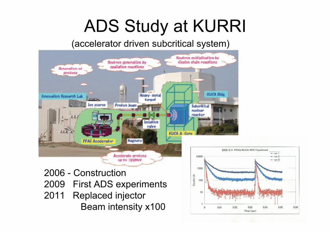
ADS Study at KURRI
2006 - Construction2009 First ADS experiments2011 Replaced injector Beam intensity x100
(accelerator driven subcritical system)

FFAG complex (1)

FFAG complex (2)

INTENSITY UPGRADEMarch 2009(starting ADS exp.)
100MeV 50pA ( a few pA @ CA target )
March 2010
100MeV 100pA ( 30 pA @ CA target )
March 2011
100MeV 1nA ( 100 pA @ CA target, unstable )
March 2012
100MeV 0.1uA equivalent* ( 100 pA @ CAtarget, broad beam )
November 2012
150MeV 0.1uA equivalent *
improve transport efficiency
( cavity voltage up 2.5kV →4kV )
H- injection
improve extraction efficiency
energy up
( history )
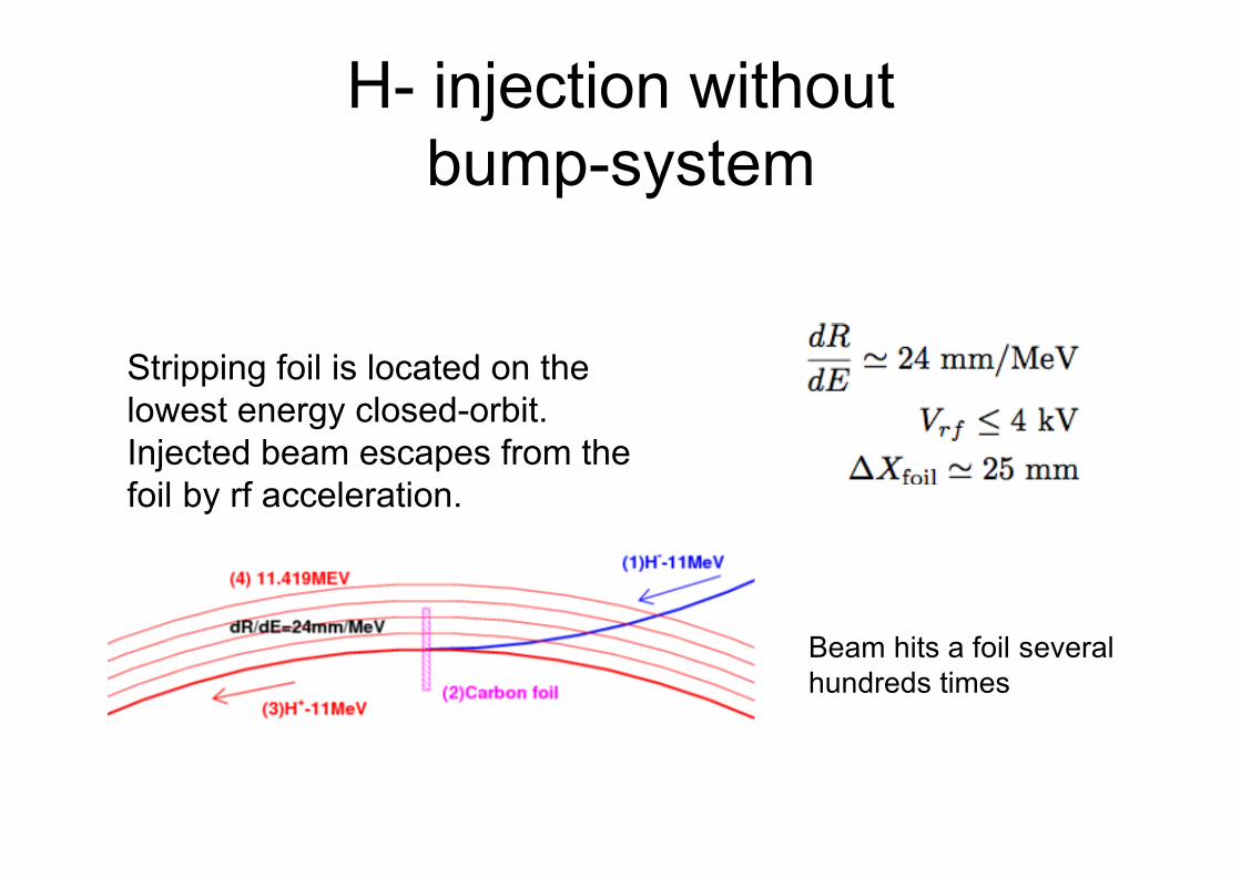
H- injection withoutbump-system
Stripping foil is located on thelowest energy closed-orbit.Injected beam escapes from thefoil by rf acceleration.
Beam hits a foil severalhundreds times

Stripping foil
Stripping efficiency > 99%

Beam current in our FFAG
Typically, the beam is lost at injection energy byfactor 100!

What is problem ?
Longitudinal Energy loss ~ 760 eV / turn (Bethe-Bloch formula) ---> (1) Synchronous phase shift (2) Boundary loss (next slide)
Transverse emittance growth ~ 1.5π mm-mrad / turn in Rms (K.Okabe, with ICOOL sim)
When a circulating beam hits the foil many times,
Overheating of the foil ---> This can give the intensity limit in future
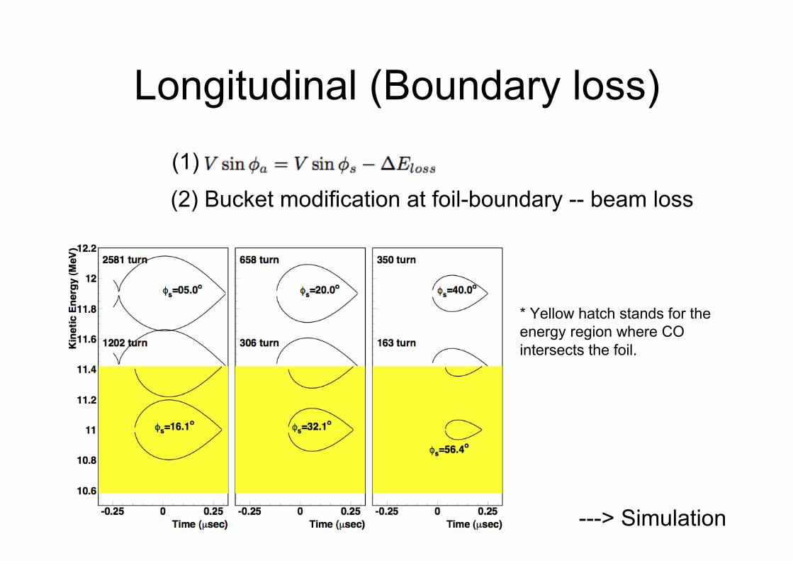
Longitudinal ( Boundary loss)
---> Simulation
(1)(2) Bucket modification at foil-boundary -- beam loss
* Yellow hatch stands for theenergy region where COintersects the foil.

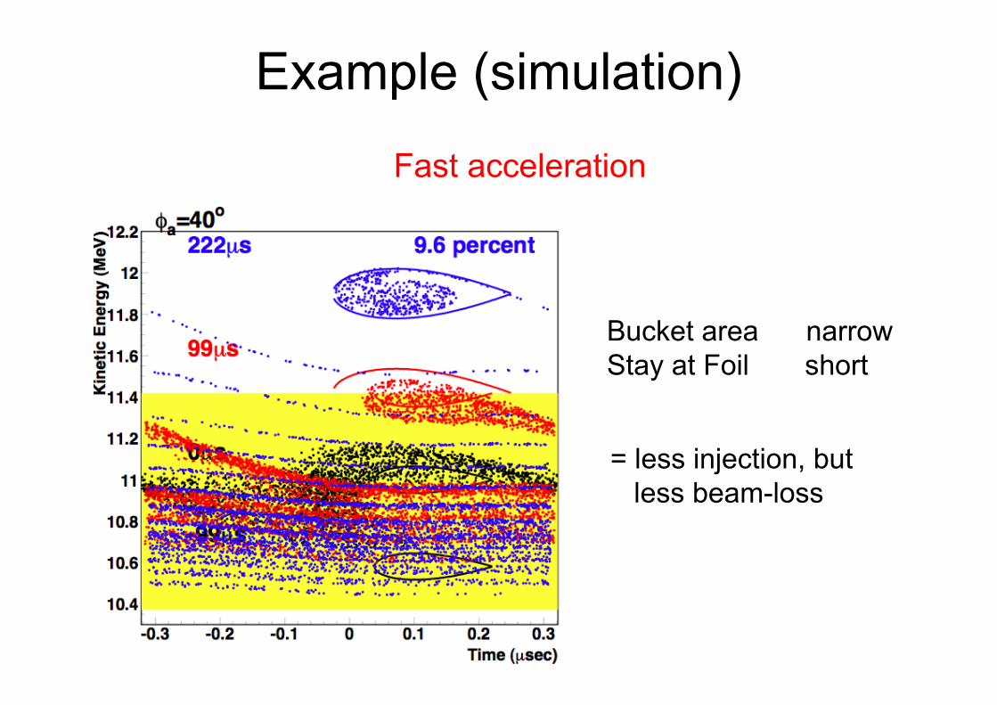
Example (simulation)
Slow acceleration
Bucket area wideStay at Foil long
= widely captured,butMany particle are lost(emittance growth)
Example (simulation)
Bucket area narrowStay at Foil short
Fast acceleration
= less injection, but less beam-loss

Simulation Results(summarized)

Transverse emittance growth
Results showedthat rms emittancelinearly increaseswith
Simulation by K.Okabe 2011
Least acceptance
by multiple-scattering

Experiments
The lifetime is determined by- Emittance growth by multiple-scattering ?- Vertical half-integer resonance ?
Capturing a short-pulsebeam (~0.2us; =1/3 turn)by a stationary bucket
Capture frequency andinjection phase (time)were optimized
However, beam survivedonly 40turns

Possible improvementagainst emittance growth
-Thinner foil to decrease the emittance growth. 20µg/cm^2 ---> 10µg/cm^2 ?
- Higher vertical aperture of foil frame 20mm ---> 30mm ?
- Fast acceleration after capture Limited by the rf voltage

Additional RF CavityTo increase rf voltage
New cavity to be installed (half-side is shown)
(1) Fast acceleration, for (1A) higher repetition, and/or (1B) larger turn separation at inj.(2) Wide bucket area
( Install this fiscal year )
RF amplifier

Space charge limit
Linac output (maximum)
Tune shift in main-ring
With those efforts, our FFAG reaches space-charge limit, someday!
POSSIBLE ACCELERATORSTUDIES WITH OUR MACHINE

1. Beam stacking at top energy orbit High intensity, low repetition
2. Multi-fish acceleration High repetition
3. Continuous acceleration by . Stationary bucket acceleration and Serpentine acceleration . Harmonic number jump acceleration . Vertical FFAG
Using unique properties of FFAG,
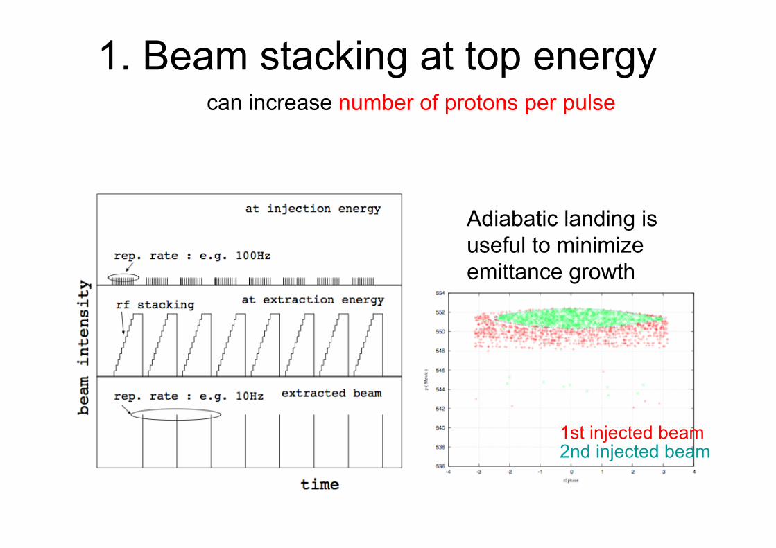
1. Beam stacking at top energycan increase number of protons per pulse
Adiabatic landing isuseful to minimizeemittance growth
1st injected beam2nd injected beam

2. Multi-Fish AccelerationY. Mori et al., PAC2001 (2001)
Two (or more) bunches with different energiesare accelerated simultaneously,by applying different rf signal for each bunch.
Interference between rf buckets can be an issue,when the frequency of them are close.

Demonstration of MFacceleration in our FFAG
is possible

3. Continuous acceleration inFFAG (1)
Stationary bucket acceleration
When it is done near the transition energy( called ‘serpentine’ acceleration )
First experiment with an electron FFAG, E. Yamakawa et al. NIM-A716(2013)

Continuous acceleration inFFAG (2)
Harmonic number jump acceleration
Rf frequency is constant,but a particle sees the same rf-phase withincreasing harmonic number.
Vertical FFAGClosed orbit shifts in vertical direction with energy,and the circumference is constant of energy.
This FFAG is isochronous at ultra-relativisticenergy region.
T. Planche, et.al. PAC09(2009)
S.J. Brooks, IPAC12(2012)

Interaction between orbitscan play an important role, but it is very complicated.
- Coupled betatron oscillations of neighboring orbit ?
- Some coupled resonance ?
Experimental studies are needed,but is it possible?

With a Simple Model
Each beam-center affects repulsing force from neighboring orbits --> Horizontal focusing --> Vertical defocusing

Field of a line charge betweenparallel plates
( B. Zotter, 1975? )
Horizontal field is rapidlydecreasing with horizontaldisplacement.
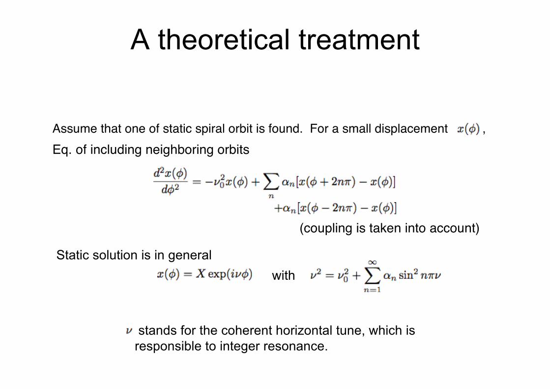
A theoretical treatment
Assume that one of static spiral orbit is found. For a small displacement ,
Static solution is in general
stands for the coherent horizontal tune, which isresponsible to integer resonance.
Eq. of including neighboring orbits
(coupling is taken into account)
with

Experiments of CWacceleration with our FFAG
(1) Stationary bucket acceleration in ERIT ring
ERIT(Energy Recovery Internal Target)
Scaling FFAG, k=1.9211MeV proton, H- injection Momentum acceptance +-20% RF 230kV at 18MHz (h=5) Bucket height +-1MeV
Injector 11MeV H- injection, Peak current 5mA x 100us (max)
11 MeV -- 12 MeV (Orbit excursion is about 20cm)

(2) Serpentine acceleration of e- beam in the main ring
Transition gamma ~ 3Bp ~ 1/100 of 11 MeV protonRevolution freq. ~ 10 MHz

SUMMARY1. A 100 MeV proton FFAG complex has been constructed in
KURRI, and started ADS studies.
2. H- injection without bump-system is adopted and the beamcurrent reached 10^10protons/pulse. We still observe arapid beam-loss of factor 100 at injection energy, which isassumed
the multiple-scattering in the stripping foil, or verticalresonance. We will overcome this beam-loss in future.
3. Our FFAG has possibilities of testing unique accelerationschemes of FFAG.
Experiments of stacking at top energy, multi-fishacceleration, and continuous acceleration are underconsideration.

----------------------------------------


