Alternative ways to explore Clinical Data – graph visualisation

EXPERIMENTAL STUDY TOWARDS ALTERNATIVE WAYS OF MACHINING CEMENTED CARBIDE
Master of Science thesis in the master program Production Engineering and Management
Freely accessible version
Jan Willem Mollema
The thesis was supervised by: Per Melin Lorenzo Daghini

Abstract Sandvik Coromant is a leading supplier of tools for the metalworking industry. Sandvik Coromant launches every year thousands of new articles. A number of manufacturing techniques are available for single piece production of tungsten carbide inserts. These methods have their advantages and their disadvantages. Some of these disadvantages might be covered by using milling, however, milling tungsten carbide is hard. An interesting aspect of brittle materials that is researched over the last years is that its properties can be changed locally by applying a large hydrostatic pressure. By doing this, brittle materials like silicon, glass and as well tungsten carbide can be successfully cut. However, this research is based on testing the hypothesis of cutting brittle materials, not on applicability in industry. Due to confidentiality reasons, it is not possible to include more information in this abstract.


Sammanfattning Sandvik Coromant är en ledande tillverkare från verktyg för metallbearbetningsindustrin. Sandvik Coromant introducerar varje år tusende nya produkter. Det finns några tillverkningsmetoder för enkelstyckstillverkning av hårdmetall vändskär. Dessa metoder har deras fördelar och nackdelar. Några av dessa nackdelar kan tacklas genom att använda fräsning, men hårdmetall är hårt att fräsa. En intressant aspekt av spröda material som har undersökts under de senaste åren är att egenskaper kan ändras lokalt om ett högt hydrostatiskt tryck tillämpas. Genom att göra så, spröda material som silicium, glas och även hårdmetall kan skäras. Dock bygger forskningen på att testa hypotesen att skära spröda material, inte på dess användbarhet inom industrin. Av sekretesskäl, är det inte möjligt att ta med mer information i denna sammanfattning.


Table of contents 1. Introduction ........................................................................................................................... 1
1.1 Background ....................................................................................................................... 1 1.2 Definitions and nomenclature ............................................................................................ 1 1.3 Manufacturing of inserts ................................................................................................... 1 1.4 Project definition ............................................................................................................... 2
2. Theoretical framework .......................................................................................................... 5 2.1 An introduction into cutting .............................................................................................. 5 2.2 Application and alternatives .............................................................................................. 9 2.3 Cutting brittle materials ................................................................................................... 11 2.4 Tool prerequisites for cutting brittle materials ................................................................ 13 2.5 Conclusion ....................................................................................................................... 16
3. Methodology, experiments and results .............................................................................. 17 4. Discussion, conclusions and future work ........................................................................... 18 5. References ............................................................................................................................. 19


1
1. Introduction 1.1 Background 1.1.1 Company and products Sandvik Coromant is part of Sandvik Machining Solutions, which is again part of the Sandvik Group. Sandvik Coromant is a ‘leading supplier of tools, tooling solutions and know-how to the metalworking industry’. ‘Sandvik Coromant has 8000 employees and is represented in 130 countries’ [1]. Nowadays, the largest part of the tools in the metalworking industry is based on inserts mounted in a cutting body. These inserts are mostly made of cemented carbide. The largest plant in the world for manufacturing such inserts is located in Gimo, Sweden. This plant is the home base for this thesis as well. 1.2 Definitions and nomenclature There is made an effort to use in this thesis a standardized way of expression, words or definitions that might be unclear or open for discussion, are listed hereunder.
- The term tungsten carbide is used when talking about the sintered state of the cemented tungsten carbide/cobalt mixture.
- Macro geometry includes the shape of the insert and chip breakers. - Micro geometry includes the edge and primary landing zone of the chip. - Dimensions of features on the insert are given in micrometers. Dimensions of other
kind are as much as possible given in millimetres. - The term full radius mill is used. Also known as ball nose end mill. - The term radius mill is used. This is a flat mill with a corner radius. Also known as
bull nose end mill. 1.3 Manufacturing of inserts There are multiple ways to manufacture inserts. Figure 1 is based on the normal production process that is designed for larger production numbers.

2
Figure 1 Overview of the production of inserts, the numbers refer to the text [2]. The process starts with powder production. Different carbides, but mainly tungsten carbide are pulverized (1) and mixed with, amongst others, cobalt (2). These readymade powders (3) can be pressed in a press tool (4) into a shaped body, defining the macro geometry of the insert. If necessary, this pressed body can be modified by conventional methods as milling and turning. After these shaping processes, the pressed body is sintered (5). Sintering is a process where crystals fuse together without reaching the molten state. The melting point for tungsten carbide is around 2800°C while the sintering process reaches approximately 1600°C [3][4]. The cobalt melts during the process and binds the tungsten carbide together, hence the name, cemented carbide. During the sintering the volume shrinks. The exact level of shrinkage depends on the mixture, but is generally about 18%. After sintering the inserts are ground (6) by different processes to define the needed geometry. After grinding the cutting edge of the insert has a sharp but weak edge. Therefore a radius will be blasted or brushed (7) onto the edge to reinforce it. To finish the insert it can be coated by a PVD or CVD process to improve wear resistance (8). PVD stands for physical vapour deposition and CVD for chemical vapour deposition. However these processes are completely different, the main difference is the used temperature. For CVD temperatures are around 1000°C, while for PVD it is only half of that. If needed, after coating some end processing can be done [5]. 1.4 Project definition The traditional mass manufacturing processes out of 1.3 are all very well known, but considering the significant lead times for machine setup and press tool manufacturing, these

3
processes are developed for mass production and not for single piece production. Further on, these processes are not designed for a first time right. Techniques that are more suitable for single piece production are laser ablation and electric discharge machining (EDM). EDM is already used for a long time and the use of laser is increasing. Since these techniques are based on thermal material removal, their disadvantage is that tensile residual stresses are created [6]. The principle and application of these techniques will be covered in paragraph 2.2.1. More about residual stresses is explained in paragraph 2.1.2. Another approach might be to use the freedom of shape of the milling process. Additionally, milling has the built in tendency to create compressive residual stresses [7]. Relative recently, in other fields of industry, the demand to mill hard and brittle materials has emerged. Since milling of brittle materials is done at micro level, it will be called micro milling. The techniques are developed, there are tools available but milling of cemented carbides is still considered as very hard or even impossible. Therefore it must be established how micro milling can complement the existing techniques, possibly even in industrialization. This background leads to the following main question: In what aspects can micro milling be applied to the machining of tungsten carbide? To help answer this main question, it can be divided into several smaller partial questions:
- Can micro milling complement existing techniques for shaping tungsten carbide and why is this?
- How can brittle materials be cut in an efficient way? - What properties do tools need to have for cutting brittle materials? - How does micro milling perform in cutting the different forms of tungsten carbide
concerning tolerances on macro and micro levels, surface properties, cost and processing times?
- How does micro milling perform in comparison to existing techniques and how can it complement these techniques?


5
2. Theoretical framework In the previous chapter some questions are defined, in this chapter information will be provided to answer the following questions through a literature research.
- Can micro milling complement existing techniques for shaping tungsten carbide and why is this?
- How can brittle materials be cut in an efficient way? - What properties do tools need to have for cutting brittle materials?
2.1 An introduction into cutting 2.1.1 The cutting process Everyday cutting that everybody knows is based on very soft bodies parted by a knife, like cutting bread or meat. Two surfaces of the knife meet at a very small angle, creating a sharp edge. If the knife is sharp, a body can be cut with very little or no observable damage to the new formed surface. Metal cutting, however, is different. Very high stresses would occur if the two faces of a cutting tool are in contact with the workpiece. A lot of heat will be generated and both the surface of the workpiece and the tool will be damaged. Therefore one of the two faces needs to be clear from the workpiece and small enough layers of metal need to be removed to allow the tool to withstand the stresses.
Figure 2 Cutting tool geometry. In Figure 2 is the nomenclature concerning tool geometry displayed. The size of the rake angle depends on the material being cut and the tool material. In earlier days, tools had large rake angles, and thus sharp edges, to decrease stresses on the tool. Today’s tools have smaller rake angles to increase tool life. In Figure 3 the direction of cutting forces on an insert are displayed. A positive (+) geometry develops shear stresses at the edge when cutting forces are applied. An initial negative angle, displayed at the right, is more capable of catching up these forces.

6
Figure 3 Forces on a positive (+) geometry (left) and forces on a negative (-) geometry (right) [5]. As can be seen in Figure 2, the whole chip is being deformed. Therefore a large amount of energy is needed to form the chip and move it across the rake face. It can be reasoned that the smaller the rake angle, the more energy is needed to deform the chip. Even more energy is needed when the negative rake angle is increased [8]. The rake angle defines partly the geometry of the insert. The chipbreakers define another large part of it [9]. In Figure 4 are different chipbreaking geometries displayed in combination with their field of application. It can be seen that on the left (WR), the negative geometry combined with the large distance between the edge and the chipbreaker can handle much larger feeds and depth of cut than the positive geometry and small distance on the right (PF). The WR is therefore for roughing and the PF for finishing. These geometries are combined with a radius on the cutting edge. The WR geometry will have a larger radius to make the edge more stable for the heavy work where the PF geometry will have a smaller radius. This radius needs to be smaller, because if cuts are made with a cutting depth that comes close to the cutting edge radius, the effective rake angle becomes negative.
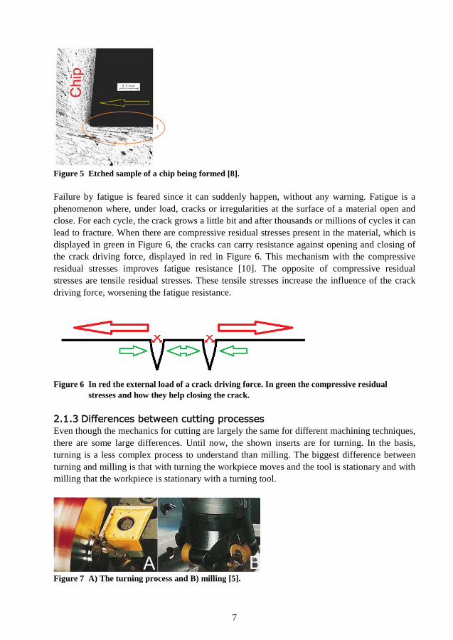
Figure 4 Chipbreaking geometry and the field of application [9]. 2.1.2 Deformation and its effects In Figure 5 the phenomenon of material being pushed into the workpiece is displayed by a cut that is suddenly stopped. The surface is etched to display the crystals. The black surface is the location where the tool was. When the cut was made, the tool moved in the direction of the arrow. It can be seen that the material flowed around the tool and that the crystals are smaller in the area in circle 1. These smaller crystals mean that they are plastically deformed. After metals are plastically deformed, there is still elastic energy present in the material. When the deforming load is released, this elastic deformation is released as well and makes the crystals expand. Because of the plastically deformed structure, the crystals cannot expand, so compressive stresses are left in the material: Compressive residual stresses [10]. Note that the tool used is positive and with a small cutting edge radius, imagine what it would look like with a negative rake angle.
7
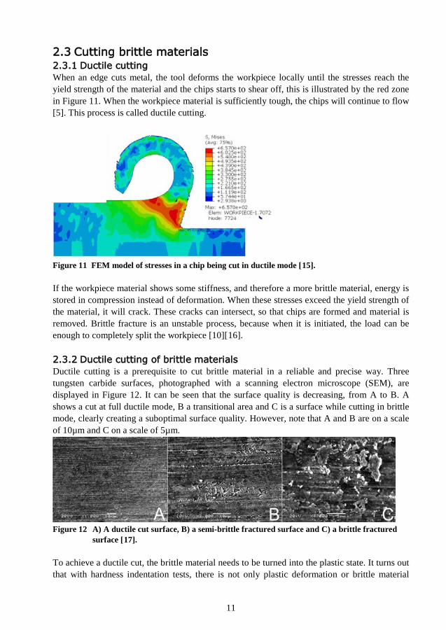
Figure 5 Etched sample of a chip being formed [8]. Failure by fatigue is feared since it can suddenly happen, without any warning. Fatigue is a phenomenon where, under load, cracks or irregularities at the surface of a material open and close. For each cycle, the crack grows a little bit and after thousands or millions of cycles it can lead to fracture. When there are compressive residual stresses present in the material, which is displayed in green in Figure 6, the cracks can carry resistance against opening and closing of the crack driving force, displayed in red in Figure 6. This mechanism with the compressive residual stresses improves fatigue resistance [10]. The opposite of compressive residual stresses are tensile residual stresses. These tensile stresses increase the influence of the crack driving force, worsening the fatigue resistance.
Figure 6 In red the external load of a crack driving force. In green the compressive residual
stresses and how they help closing the crack. 2.1.3 Differences between cutting processes Even though the mechanics for cutting are largely the same for different machining techniques, there are some large differences. Until now, the shown inserts are for turning. In the basis, turning is a less complex process to understand than milling. The biggest difference between turning and milling is that with turning the workpiece moves and the tool is stationary and with milling that the workpiece is stationary with a turning tool.
Figure 7 A) The turning process and B) milling [5].

8
2.1.4 Chip thickness With different processes, different chips are made. One, for this thesis at least, important property of a chip is its thickness. Since the chip is deformed when it is made, the thickness of the chip before it was made, will be of interest: The undeformed chip thickness. The method to determine this value is dependent on the used cutting method. For a process comparable to the processes shown in Figure 7, there are two options.
For small feed rates where �2𝑅 ∙ 𝑎𝑝 − 𝑎𝑝2 > 𝑎𝑓 Figure 8A and equation (1) is applicable. Here,
R is the tool radius, not the cutting edge radius.
Figure 8 A) Sketch for small feed rates and in B) a sketch for large feed rates [25].
𝑎𝑚𝑎𝑥 = 𝑅 − �𝑅2 + 𝑎𝑓2 − 2𝑎𝑓 ∙ �2𝑅 ∙ 𝑎𝑝 − 𝑎𝑝2 (1)
For large feed rates when �2𝑅 ∙ 𝑎𝑝 − 𝑎𝑝2 ≤ 𝑎𝑓 then Figure 8B is applicable and 𝑎𝑚𝑎𝑥 = 𝑎𝑝
[25]. Equation (2) is applicable when a full radius mill is used.
𝑎𝑚𝑎𝑥 = 𝑎𝑓 ∙ �𝑎𝑝𝐷𝑐
(2)

9
2.2 Application and alternatives 2.2.1 What is EDM and laser ablation Conventionally, powder metallurgy and grinding are used to shape parts of tungsten carbide, but because of the high costs for tool making and the long lead times, these techniques are only suitable for larger scale production. EDM is a process that uses electrical sparks to remove material from the workpiece. Roughly, there are two kinds of EDM that differ in their application, see Figure 9. First, there is die sinking where the shape of the electrode is copied into the workpiece. Since material is removed from both the workpiece and the electrode, several electrodes have to be used to copy all the details. Second, there is wire cutting EDM. With this process a wire is fed through the workpiece, by moving the workpiece, shapes can be cut out of conducting material.
Figure 9 The principle of wire EDM (left) and die sink EDM (right) [11]. The main principle of material removal in EDM is melting. Because the melting is followed by rapid solidification of the workpiece material, tensile residual stresses are caused at the surface of the workpiece [6]. Multiple electrodes are needed since the process takes away material from both the electrode and the workpiece. The electrodes are mostly manufactured by milling. Laser ablation is a process that uses the intensity of a laser beam to melt material locally in order to evaporate or sublimate it [3]. To limit the needed power of the laser and the energy put in the material, pulsed lasers are used. When pulses are used in the nanosecond region, there is a significant heat affected zone. The thickness of this zone decreases when pulses are used in the picosecond region, or even in the femtosecond region. The influence of tensile residual stresses is of great importance. Residual stresses in the coating and in the subsurface substrate, which is the tungsten carbide, determine the performance of cutting tools. Tensile residual stresses in the subsurface substrate might introduce tensile stresses in the PVD coating, potentially causing flaking of the coating with pieces of tungsten carbide attached to it [12]. It is already stated that EDM and laser ablation create these tensile residual stresses. However, a sand blasting process can precede the coating process. The blasting might be enough to take away the tensile stresses and to introduce compressive stresses, and thus solving the problem. But it depends on how large the heat affected zone is, how deep the blasting reaches and whether a PVD or a CVD coating is applied. Nevertheless, currently it is still unclear what the exact mechanisms are behind these processes [13].

10
2.2.2 Manufacturing of geometries Compared to the previously mentioned methods, milling can be a suitable option. Milling is a process with defined cutting edges and small geometries are proven to be possible. Material removal rates for milling in tungsten carbide are expected to be the same or higher compared with laser. Additionally, process times might be comparable towards EDM. However, the initial investment costs for a milling machine are a lot smaller than those for a laser. As well, energy use of a milling machine is significantly lower than that of an EDM machine. Besides this, an EDM machine needs to be combined with a milling machine for the electrodes anyhow. A feature that is especially hard, or even impossible, to manufacture with both EDM and laser is internal thread. Milling is capable of doing this. Thread is not a feature to be known on the inserts of today, but it might be useful in the future. Compared to grinding, milling has a larger freedom of shape. Milling is in this application not in need of cutting fluids and in literature a better surface is described, which is displayed in Figure 10 [14].
Figure 10 SEM micrographs with on the left a ground (ap=0.01mm, SiC wheel, vc=30m/s) surface
and on the right the same surface after it was milled (ap=0.002mm, af=0.01mm/rev) [14].
11
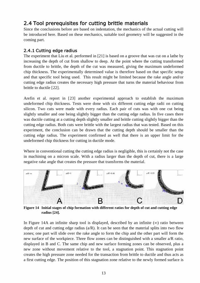
2.3 Cutting brittle materials 2.3.1 Ductile cutting When an edge cuts metal, the tool deforms the workpiece locally until the stresses reach the yield strength of the material and the chips starts to shear off, this is illustrated by the red zone in Figure 11. When the workpiece material is sufficiently tough, the chips will continue to flow [5]. This process is called ductile cutting.
Figure 11 FEM model of stresses in a chip being cut in ductile mode [15]. If the workpiece material shows some stiffness, and therefore a more brittle material, energy is stored in compression instead of deformation. When these stresses exceed the yield strength of the material, it will crack. These cracks can intersect, so that chips are formed and material is removed. Brittle fracture is an unstable process, because when it is initiated, the load can be enough to completely split the workpiece [10][16]. 2.3.2 Ductile cutting of brittle materials Ductile cutting is a prerequisite to cut brittle material in a reliable and precise way. Three tungsten carbide surfaces, photographed with a scanning electron microscope (SEM), are displayed in Figure 12. It can be seen that the surface quality is decreasing, from A to B. A shows a cut at full ductile mode, B a transitional area and C is a surface while cutting in brittle mode, clearly creating a suboptimal surface quality. However, note that A and B are on a scale of 10µm and C on a scale of 5µm.
Figure 12 A) A ductile cut surface, B) a semi-brittle fractured surface and C) a brittle fractured
surface [17]. To achieve a ductile cut, the brittle material needs to be turned into the plastic state. It turns out that with hardness indentation tests, there is not only plastic deformation or brittle material

12
removal, but plastic extrusion as well. Figure 13 is a micrograph of the very brittle amorphous silicon. At the sides of the indentation is plastic extrusion visible [18].
Figure 13 SEM micrograph of amorphous silicon after static indentation of 0.15N [18]. Bridgman showed in one of his articles [19] that many brittle materials can behave like ductile materials when they are under high hydrostatic loads. However the elastic energy stored in the material cannot exceed a limit, otherwise the material would crack. Because every material has a resistance towards the growth of a crack, a crack will propagate when a crack driving force, a so called intensity factor, reaches the resistance value. However, when at this moment compressive stresses are introduced, the property of interest is that the intensity factor will be reduced. When the compressive stress is so large that the intensity becomes smaller than the resistance, there will be no crack propagation [20]. So when compressive stresses are introduced in the cutting area by tool geometry and cutting parameters, the material properties change locally so that it can be cut in a ductile mode. Based on indentation, Liu et al. developed an energy model for tungsten carbide in order to determine a value for the point where the deformation transforms from brittle towards ductile [21]. This value is expressed as the undeformed chip thickness. Using the model they calculated a value of 2.114µm. Since the indentation differs in principle from cutting this is more an absolute theoretical value. This maximum chip thickness is the absolute maximum that can be done in cutting. Due to some inaccuracy in the model because of a wrong parameter, the experimentally determined maximum chip thickness was 2.485µm.
13
2.4 Tool prerequisites for cutting brittle materials Since the conclusions before are based on indentation, the mechanics of the actual cutting will be introduced here. Based on these mechanics, suitable tool geometry will be suggested in the coming part. 2.4.1 Cutting edge radius The experiment that Liu et al. performed in [21] is based on a groove that was cut on a lathe by increasing the depth of cut from shallow to deep. At the point where the cutting transformed from ductile to brittle, the depth of the cut was measured, giving the maximum undeformed chip thickness. The experimentally determined value is therefore based on that specific setup and that specific tool being used. This result might be limited because the rake angle and/or cutting edge radius creates the necessary high pressure that turns the material behaviour from brittle to ductile [22]. Arefin et al. report in [23] another experimental approach to establish the maximum undeformed chip thickness. Tests were done with six different cutting edge radii on cutting silicon. Two cuts were made with every radius. Each pair of cuts was with one cut being slightly smaller and one being slightly bigger than the cutting edge radius. In five cases there was ductile cutting at a cutting depth slightly smaller and brittle cutting slightly bigger than the cutting edge radius. Both cuts were brittle with the largest radius that was tested. Based on this experiment, the conclusion can be drawn that the cutting depth should be smaller than the cutting edge radius. The experiment confirmed as well that there is an upper limit for the undeformed chip thickness for cutting in ductile mode. Where in conventional cutting the cutting edge radius is negligible, this is certainly not the case in machining on a micron scale. With a radius larger than the depth of cut, there is a large negative rake angle that creates the pressure that transforms the material.
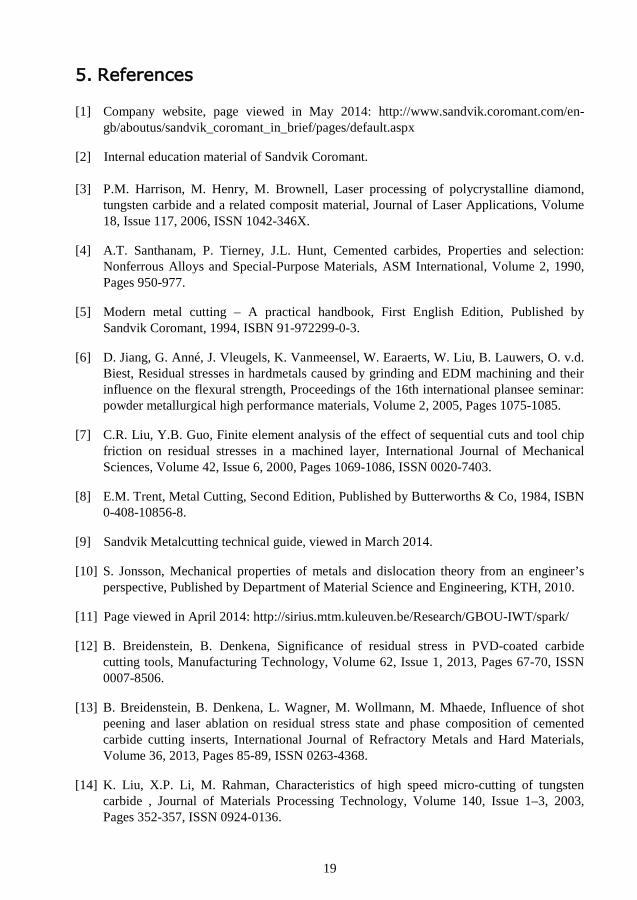
Figure 14 Initial stages of chip formation with different ratios for depth of cut and cutting edge
radius [24]. In Figure 14A an infinite sharp tool is displayed, described by an infinite (∞) ratio between depth of cut and cutting edge radius (a/R). It can be seen that the material splits into two flow zones; one part will slide over the rake angle to form the chip and the other part will form the new surface of the workpiece. Three flow zones can be distinguished with a smaller a/R ratio, displayed in B and C. The same chip and new surface forming zones can be observed, plus a new zone without movement relative to the tool, a stagnation point. This stagnation point creates the high pressure zone needed for the transaction from brittle to ductile and thus acts as a first cutting edge. The position of this stagnation zone relative to the newly formed surface is

14
more or less independent of depth of cut. In picture D, there is a too large radius, or a too small depth of cut, making the rake angle so negative that most of the material is pushed into the new surface, which is obviously not optimal. Concerning the forces involved in cutting brittle materials, it can be said that generally the thrust force is large compared to the cutting force, where the contrary is true in conventional cutting. Both the thrust force and the cutting force increase with a decreasing a/R ratio when it is smaller than 1. However, a negative thrust force can be seen with sharp tools, since these tend to be pulled into the workpiece [24]. Therefore, out of an efficiency point of view it is desirable to:
- remove as much as possible material - with as little as possible forces - with as little as possible plastic deformation to the newly formed workpiece.
This seems to be possible with a tool that has a cutting edge radius larger than the depth of cut, or an a/R between 0.8 and 0.4. 2.4.2 Material To cut tungsten carbide in an endurable way, a tool made of a harder material is needed. This pretty much narrows the selection to tools made of a plate of poly crystalline diamond (PCD), mono crystalline diamond (MCD) or cubic boron nitride (CBN) brazed on a tungsten carbide body or a tool with a tungsten carbide body that is coated with diamond. In all consulted research papers where tungsten carbide is cut, experiments are conducted with CBN tools [14][17][20][21][25]. In other used papers where other brittle materials like silicon and glass are cut, this is done with diamond tools [18][19][23]. In an experiment to study tool wear in tungsten carbide, related to cutting speed, the diagrams in Figure 15 were obtained. The cutting parameters were ap = 0.003mm, af = 0.01mm/rev [25].
Figure 15 Radial (Fx) and tangential (Fz) cutting forces in tungsten carbide against the cutting
distance for different cutting speeds [25]. These diagrams show that tool wear with CBN tools increases significantly with higher cutting speeds. These experiments are characterized by material removal rates, the amount of material removed per time unit (MRR), of approximately 0.75mm3/min for about four minutes period, after which the tool is worn.

15
Diamond coated tungsten carbide tools that are designed explicitly to mill tungsten carbide report material removal rates up to 2.3mm3/min for 62 minutes at 126m/min. This information however comes from the tool producer Union Tool and is based on another grade of cemented carbide, which might cause a discrepancy [26]. Table 1 lists some physical properties of four different materials. Especially the superior hardness of CBN, PCD and MCD towards tungsten carbide is interesting. The difference between MCD and PCD is that PCD are diamond crystals bound together by cobalt, much like cemented carbides. Because of the cobalt matrix, EDM can be used to shape PCD tools what is a big advantage. MCD tools have to be ground with diamond, however, special lasers might be able to shape these tools as well. Table 1 Physical properties of CBN, PCD and tungsten carbide. CBN [21] PCD [3] Tungsten carbide [3] MCD [27]
Density (g/cm3) 3.5-4.2 3-4 16 3.52
Thermal conductivity (W/m·K) 300-600 540 100 2100
Modulus of elasticity (GPa) 680 749-953 680 1220
Vickers hardness (kg/mm2) 4000-6000 5098 1730 7000-10000
Melting point (°C) 2973 1257 2577 - Nota Bene: These values depend on the grade of the materials. Diamond has no melting point since it degrades into carbon at approximately 700°C at normal pressure in contact with oxygen.

16
2.5 Conclusion In the previous chapter information is provided to answer the defined questions. To end this chapter, the questions will be answered shortly. Can micro milling complement existing techniques for shaping tungsten carbide and why is this? Micro milling can complement existing techniques since the process is capable of creating shapes that are not possible by grinding, EDM or laser ablation. Additionally, for applications where residual stresses are considered to play a significant role, milling inherently creates the right residual stresses, this unlike laser ablation and EDM. How can brittle materials be cut in an efficient way? With indentation tests in brittle material, cracks and brittle material removal are expected. However, in some cases, under the right conditions, plastic extrusion of material can be observed around the indentation zone. When a cut is made with a cutting depth smaller than the cutting edge radius, large hydrostatic pressure is caused under the tool, potentially allowing the material to become less brittle and thus allowing ductile cutting. However, there is a limit to both the cutting edge radius as the undeformed chip thickness. When exceeding one of these limits it will not be possible to cut ductile. What properties do tools need to have for cutting brittle materials? Tools need to withstand the large pressures that are needed to cut the material in the ductile state. Since the material to be cut is already one of the hardest existing materials, only CBN or diamond based cutting materials are serious options. Additionally, the tool needs a cutting edge that is slightly larger than the cutting depth.

17
3. Methodology, experiments and results CONFIDENTIAL

18
4. Discussion, conclusions and future work CONFIDENTIAL
19
5. References [1] Company website, page viewed in May 2014: http://www.sandvik.coromant.com/en-
gb/aboutus/sandvik_coromant_in_brief/pages/default.aspx
[2] Internal education material of Sandvik Coromant. [3] P.M. Harrison, M. Henry, M. Brownell, Laser processing of polycrystalline diamond,
tungsten carbide and a related composit material, Journal of Laser Applications, Volume 18, Issue 117, 2006, ISSN 1042-346X.
[4] A.T. Santhanam, P. Tierney, J.L. Hunt, Cemented carbides, Properties and selection: Nonferrous Alloys and Special-Purpose Materials, ASM International, Volume 2, 1990, Pages 950-977.
[5] Modern metal cutting – A practical handbook, First English Edition, Published by Sandvik Coromant, 1994, ISBN 91-972299-0-3.
[6] D. Jiang, G. Anné, J. Vleugels, K. Vanmeensel, W. Earaerts, W. Liu, B. Lauwers, O. v.d. Biest, Residual stresses in hardmetals caused by grinding and EDM machining and their influence on the flexural strength, Proceedings of the 16th international plansee seminar: powder metallurgical high performance materials, Volume 2, 2005, Pages 1075-1085.
[7] C.R. Liu, Y.B. Guo, Finite element analysis of the effect of sequential cuts and tool chip friction on residual stresses in a machined layer, International Journal of Mechanical Sciences, Volume 42, Issue 6, 2000, Pages 1069-1086, ISSN 0020-7403.
[8] E.M. Trent, Metal Cutting, Second Edition, Published by Butterworths & Co, 1984, ISBN 0-408-10856-8.
[9] Sandvik Metalcutting technical guide, viewed in March 2014.
[10] S. Jonsson, Mechanical properties of metals and dislocation theory from an engineer’s perspective, Published by Department of Material Science and Engineering, KTH, 2010.
[11] Page viewed in April 2014: http://sirius.mtm.kuleuven.be/Research/GBOU-IWT/spark/
[12] B. Breidenstein, B. Denkena, Significance of residual stress in PVD-coated carbide cutting tools, Manufacturing Technology, Volume 62, Issue 1, 2013, Pages 67-70, ISSN 0007-8506.
[13] B. Breidenstein, B. Denkena, L. Wagner, M. Wollmann, M. Mhaede, Influence of shot peening and laser ablation on residual stress state and phase composition of cemented carbide cutting inserts, International Journal of Refractory Metals and Hard Materials, Volume 36, 2013, Pages 85-89, ISSN 0263-4368.
[14] K. Liu, X.P. Li, M. Rahman, Characteristics of high speed micro-cutting of tungsten carbide , Journal of Materials Processing Technology, Volume 140, Issue 1–3, 2003, Pages 352-357, ISSN 0924-0136.

20
[15] J. Liu, Y. Bai, C. Xu, Evaluation of ductile fracture models in finite element simulation of
metal cutting processes, Journal of Manufacturing Science and Engineering, Volume 136, Issue 1, 2014, Pages 011010, ISSN 1087-1357.
[16] T. Atkins, Science and engineering of cutting, Published by Butterworth-Heinemann, Elsevier, 2009, ISBN 978-0-7506-8531-3.
[17] K. Liu, X.P. Li, M. Rahman , X. Liu, A study of the cutting modes in the grooving of tungsten carbide, The International Journal of Advanced Manufacturing Technology, Volume 24, Issue 5, 2004, Pages 321-326, ISSN 0268-3768.
[18] B.V. Tanikella, A.H. Somasekhar, Phase transformations during microcutting tests on silicon, Applied Physics Letters, Volume 69, Issue 19, 1996, Pages 2870-2872, ISSN 0003-6951.
[19] P.W. Bridgman, I. Šimon, Effects of very high pressures on glass, Journal of Applied Physics, Volume 24, Issue 4, 1953, Pages 406-413, ISSN 0021-8979.
[20] K. Liu, X. Li, S. Liang, The mechanism of ductile chip formation in cutting of brittle materials, The International Journal of Advanced Manufacturing Technology, Volume 33, Issue 9, 2007, Pages 875-884, ISSN 0268-3768.
[21] K Liu, X.P Li, Ductile cutting of tungsten carbide, Journal of Materials Processing Technology, Volume 113, Issue 1-3, 2001, Pages 348-354, ISSN 0924-0136.
[22] R. Komanduri, N. Chandrasekaran, L.M. Raff, Effect of tool geometry in nanometric cutting: a molecular dynamics simulation approach, Wear, Volume 219, Issue 1, 1998, Pages 84-97, ISSN 0043-1648.
[23] S. Arefin, X. Li, M. Rahman, K. Liu, The upper bound of tool edge radius for nanoscale ductile mode cutting of silicon wafer, The International Journal of Advanced Manufacturing Technology, Volume 31, Issue 7, 2007, Pages 655-662, ISSN 0268-3768.
[24] S.V. Hosseini, M. Vahdati, Modeling the effect of tool edge radius on contact zone in nanomachining, Computational Materials Science, Volume 65, Issue , 2012, Pages 29-36, ISSN 0927-0256.
[25] K. Liu, X.P. Li, M. Rahman, X.D. Liu, CBN tool wear in ductile cutting of tungsten carbide, Wear, Volume 255, Issue 7, 2003, Pages 1344-1351, ISSN 0043-1648.
[26] Brochure Union Tool, page viewed in February 2014: http://www.uniontool.com/cgi-bin/pdfs/news/UDC%20series_13-10-31.pdf
[27] T.J. Clark, R.C. DeVries, Superabrasives and Ultrahard Tool Materials, Properties and Selection: Nonferrous Alloys and Special-Purpose Materials, ASM International, Volume 2, 1990, Pages 1008-1018.