Experimental Study on Machinability of Ti-6Al-4V in Micro ... · In the case of tool wear, small...
5
Abstract—In this paper, the characteristics of micro end-milling of titanium alloy (Ti-6Al-4V), which is representative difficult-to-machine material, are experimentally investigated. The spindle speed and feed per tooth are considered as independent factors, and the resulting milling forces, burr formation, chip morphology and tool wear are studied through a series of micro end-milling experiments. In the cases of milling forces and burr formation, the feed per tooth is a dominant factor. It is found that the milling forces linearly increased with the increase of feed per tooth, and that the low feed per tooth generated more top burrs at the edges of milled slots. Meanwhile, low feed per tooth can generate long and connected chips and also cause larger tool wear at the cutting edge of micro end-mill. Index Terms— Micro End-Milling, Titanium Alloy, Milling Force, Burr Formation, Chip Morphology, Tool Wear I. INTRODUCTION ITANIUM alloy has been an attractive material for aerospace and biomedical industries because of their superb mechanical property, high strength-to-weight ratio, corrosion resistance, and biocompatibility. However, titanium alloy is classified as a difficult-to-machine material due to strong affinity with tool materials and low thermal conductivity which can result in excessive tool wear [1, 2]. Due to these reasons, researches on mechanical machining of titanium alloys have been actively conducted. Meanwhile, in recent years, there has been an increasing need to fabricate miniature parts and micro-scale features in a wide range of engineering materials. In this context, micro-milling is a key machining process which could be used to make complex three-dimensional micro-scale components with high aspect ratios. Micro-milling demonstrates distinguishing features compared to macro-scale milling in several ways. Micro tools with diameters in the range of sub-millimeter have relatively small stiffness, high risk of tool breakage, and high tool wear. Moreover, an edge radius of a micro tool becomes more significant in micro-milling process Manuscript received March 14, 2014; revised March 31, 2014. This research was supported by Basic Science Research Program through the National Research Foundation of Korea(NRF) funded by the Ministry of Education (2013R1A1A2012313). Dae Hoon Kim is with the Dept. of Mechanical Engineering, Graduate School, Sungkyunkwan Univ. 2066, Seobu-ro, Jangan-gu, Suwon-si, Gyeonggi, South Korea, 440-746 (e-mail: [email protected]). Pil-Ho Lee is with the Dept. of Mechanical Engineering, Graduate School, Sungkyunkwan Univ. 2066, Seobu-ro, Jangan-gu, Suwon-si, Gyeonggi, South Korea, 440-746 (e-mail: [email protected]). Sang Won Lee is with the School of Mechanical Engineering, Sungkyunkwan Univ. 2066, Seobu-ro, Jangan-gu, Suwon-si, Gyeonggi, South Korea, 440-746 (phone: 82-31-290-7467; fax: 82-31-299-4690; e-mail: [email protected]). since its magnitude is comparable to or smaller than the uncut chip thickness which is the thickness of the material to be removed. As a result, chips are not generated for every pass due to ploughing effect [3]. This ploughing effect could significantly increase cutting force, burr formation, surface roughness, and tool wear [4, 5, 6, 7]. The above-mentioned problems can be more significant in micro-scale machining of difficult-to-machine materials. However, a limited number of researches on micro-scale machining of difficult-to-machine materials have been studied. Aramcharoen and Mativenga conducted the micro-milling of hardened tool steel in order to investigate the size effect [8]. The results showed that the specific cutting force, surface finish, and burr formation were changed depending on the ratio of undeformed chip thickness to the cutting edge radius. In the case of titanium alloy, Schueler et al. studied the burr formation and surface generation characteristics in the micro end-milling of Ti-6Al-4V and Ti-6Al-7Nb with the micro end-mills having the diameter of 48 um [9]. The massive wavy-type burrs were formed at the low depth of cut, but the surface roughness did not differ according to feed rates solely. Ramesh et al. also investigated the burr formation and surface quality in the micro milling of Ti-6Al-4V [10]. Several types of burr were observed at different locations of the machined groove and the effect of machining parameters on burr size were analyzed. In addition, they reported that surface roughness increased with the increase in spindle speed, feed rate, and depth of cut. Thepsonthi and Özel conducted the multi-objective process optimization in order to obtain optimal process parameters in the micro end-milling of Ti-6Al-4V in terms of the burr formation and surface roughness [11]. They concluded that axial depth of cut is a major process parameter causing top burr formation and feed rate is a major process parameter affecting surface roughness. This paper addresses comprehensive analysis on the micro-scale end-milling process of titanium alloy – Ti-6Al-4V by investigating the effects of machining parameters on milling forces, burr formation, chip morphology, and tool wear, respectively. The experimental results show that large feed per tooth (5 um/tooth) results in the increase in the resultant milling force and that large spindle speed (60,000 RPM) and feed per tooth (5 um/tooth) reduce the top-burr width. In addition, small feed per tooth (1 um/tooth) can generate long and connected chips while larger feed per tooth (3 and 5 um/tooth) can produce discontinuous chips. In the case of tool wear, small feed per tooth (1 um/tooth) can lead to large tool wear along the cutting edge of the micro endmill. Experimental Study on Machinability of Ti-6Al-4V in Micro End-Milling Dae Hoon Kim, Pil-Ho Lee, and Sang Won Lee T Proceedings of the World Congress on Engineering 2014 Vol II, WCE 2014, July 2 - 4, 2014, London, U.K. ISBN: 978-988-19253-5-0 ISSN: 2078-0958 (Print); ISSN: 2078-0966 (Online) WCE 2014
Transcript of Experimental Study on Machinability of Ti-6Al-4V in Micro ... · In the case of tool wear, small...

Abstract—In this paper, the characteristics of micro
end-milling of titanium alloy (Ti-6Al-4V), which is representative difficult-to-machine material, are experimentally investigated. The spindle speed and feed per tooth are considered as independent factors, and the resulting milling forces, burr formation, chip morphology and tool wear are studied through a series of micro end-milling experiments. In the cases of milling forces and burr formation, the feed per tooth is a dominant factor. It is found that the milling forces linearly increased with the increase of feed per tooth, and that the low feed per tooth generated more top burrs at the edges of milled slots. Meanwhile, low feed per tooth can generate long and connected chips and also cause larger tool wear at the cutting edge of micro end-mill.
Index Terms— Micro End-Milling, Titanium Alloy, Milling Force, Burr Formation, Chip Morphology, Tool Wear
I. INTRODUCTION ITANIUM alloy has been an attractive material for aerospace and biomedical industries because of their
superb mechanical property, high strength-to-weight ratio, corrosion resistance, and biocompatibility. However, titanium alloy is classified as a difficult-to-machine material due to strong affinity with tool materials and low thermal conductivity which can result in excessive tool wear [1, 2]. Due to these reasons, researches on mechanical machining of titanium alloys have been actively conducted.
Meanwhile, in recent years, there has been an increasing need to fabricate miniature parts and micro-scale features in a wide range of engineering materials. In this context, micro-milling is a key machining process which could be used to make complex three-dimensional micro-scale components with high aspect ratios. Micro-milling demonstrates distinguishing features compared to macro-scale milling in several ways. Micro tools with diameters in the range of sub-millimeter have relatively small stiffness, high risk of tool breakage, and high tool wear. Moreover, an edge radius of a micro tool becomes more significant in micro-milling process
Manuscript received March 14, 2014; revised March 31, 2014. This research was supported by Basic Science Research Program through the National Research Foundation of Korea(NRF) funded by the Ministry of Education (2013R1A1A2012313).
Dae Hoon Kim is with the Dept. of Mechanical Engineering, Graduate School, Sungkyunkwan Univ. 2066, Seobu-ro, Jangan-gu, Suwon-si, Gyeonggi, South Korea, 440-746 (e-mail: [email protected]).
Pil-Ho Lee is with the Dept. of Mechanical Engineering, Graduate School, Sungkyunkwan Univ. 2066, Seobu-ro, Jangan-gu, Suwon-si, Gyeonggi, South Korea, 440-746 (e-mail: [email protected]).
Sang Won Lee is with the School of Mechanical Engineering, Sungkyunkwan Univ. 2066, Seobu-ro, Jangan-gu, Suwon-si, Gyeonggi, South Korea, 440-746 (phone: 82-31-290-7467; fax: 82-31-299-4690; e-mail: [email protected]).
since its magnitude is comparable to or smaller than the uncut chip thickness which is the thickness of the material to be removed. As a result, chips are not generated for every pass due to ploughing effect [3]. This ploughing effect could significantly increase cutting force, burr formation, surface roughness, and tool wear [4, 5, 6, 7].
The above-mentioned problems can be more significant in micro-scale machining of difficult-to-machine materials. However, a limited number of researches on micro-scale machining of difficult-to-machine materials have been studied. Aramcharoen and Mativenga conducted the micro-milling of hardened tool steel in order to investigate the size effect [8]. The results showed that the specific cutting force, surface finish, and burr formation were changed depending on the ratio of undeformed chip thickness to the cutting edge radius. In the case of titanium alloy, Schueler et al. studied the burr formation and surface generation characteristics in the micro end-milling of Ti-6Al-4V and Ti-6Al-7Nb with the micro end-mills having the diameter of 48 um [9]. The massive wavy-type burrs were formed at the low depth of cut, but the surface roughness did not differ according to feed rates solely. Ramesh et al. also investigated the burr formation and surface quality in the micro milling of Ti-6Al-4V [10]. Several types of burr were observed at different locations of the machined groove and the effect of machining parameters on burr size were analyzed. In addition, they reported that surface roughness increased with the increase in spindle speed, feed rate, and depth of cut. Thepsonthi and Özel conducted the multi-objective process optimization in order to obtain optimal process parameters in the micro end-milling of Ti-6Al-4V in terms of the burr formation and surface roughness [11]. They concluded that axial depth of cut is a major process parameter causing top burr formation and feed rate is a major process parameter affecting surface roughness.
This paper addresses comprehensive analysis on the micro-scale end-milling process of titanium alloy – Ti-6Al-4V by investigating the effects of machining parameters on milling forces, burr formation, chip morphology, and tool wear, respectively. The experimental results show that large feed per tooth (5 um/tooth) results in the increase in the resultant milling force and that large spindle speed (60,000 RPM) and feed per tooth (5 um/tooth) reduce the top-burr width. In addition, small feed per tooth (1 um/tooth) can generate long and connected chips while larger feed per tooth (3 and 5 um/tooth) can produce discontinuous chips. In the case of tool wear, small feed per tooth (1 um/tooth) can lead to large tool wear along the cutting edge of the micro endmill.
Experimental Study on Machinability of Ti-6Al-4V in Micro End-Milling
Dae Hoon Kim, Pil-Ho Lee, and Sang Won Lee
T
Proceedings of the World Congress on Engineering 2014 Vol II, WCE 2014, July 2 - 4, 2014, London, U.K.
ISBN: 978-988-19253-5-0 ISSN: 2078-0958 (Print); ISSN: 2078-0966 (Online)
WCE 2014
II. MICRO END-MILLING EXPERIMENTS
A. Experimental Setup The micro end-milling experiments of Ti-6Al-4V were
performed in the miniaturized machine tool system, which is shown in Fig. 1. The miniaturized machine tool consisted of three stepper motor driven linear translation stages (MX80S) for the precision positioning system and the high speed ultra-high precision brushless DC motor spindle (E-800Z) with the maximum spindle speed of 80,000 RPM in the horizontal configuration. In addition, the relative motion between a micro end-milling tool and a workpiece was controlled by the PMAC (CEM 104) motion controller. The 2-axis load cell was installed to stepper motor driven linear translation stages to capture the force signals during the micro end-milling process. The 2-axis load cell was connected with strain gage amplifier (DPM-911A) NI-DAQ (USB-6251) for process monitoring and data capturing. The overall size of the miniaturized milling machine tool system was 210 x 190 x 220 mm.
The tool used during the micro end-milling experiments was an ultra-fine tungsten carbide tool (JJ Tools). The micro endmill was a flat end-mill having two flutes having a diameter of 500 um. The workpiece material was representative titanium alloy, Ti-6Al-4V. The workpiece had the size 30×30×4.5 mm, and was attached to the 2-axis load cell. The full-immersion milling was conducted with the axial depth of cut of 100 um, and ten slots of 30 mm in length (total length of cut: 300 mm) were machined. The experimental conditions are summarized in Table 1. In addition, burrs of machined slots, tool wear, and chip morphology were measured by using the optical microscope (OLYMPUS BX51M).
Fig. 1. Experimental setup
TABLE I EXPERIMENTAL CONDITIONS
Workpiece Ti-6Al-4V (Grade 5)
Milling tool Two flat carbide micro end-mill Tool diameter: 500 um
Milling type Full-immersion milling
Cutting fluid Dry cutting
Axial depth of cut 100 um
Length of cut Ten micro-milled slots (30 mm) Total length: 300 mm
B. Experimental Design The micro end-milling experiments were designed based
on Taguchi method with two factors and three levels. Two independent factors of spindle speed and feed per tooth were considered. Three levels of the spindle speed were selected as 30,000, 45,000, and 60,000 RPM and those in the case of feed per tooth were 1, 3, and 5 um/tooth. The results of experimental design, Taguchi orthogonal arrays (L9), are summarized in Table 2.
TABLE 2
EXPERIMENTAL DESIGN OF MICRO-MILLING
Run Spindle speed (RPM)
Feed per tooth (um/tooth)
1 30,000 1
2 30,000 3
3 30,000 5
4 45,000 1
5 45,000 3
6 45,000 5
7 60,000 1
8 60,000 3
9 60,000 5
In order to investigate the machinability of Ti-6Al-4V in
the micro end-milling process according to the changes in machining parameters, the milling forces, burr formation, chip morphology, and tool wear were observed and analyzed.
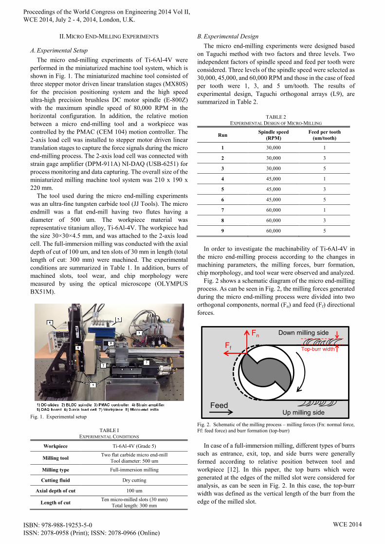
Fig. 2 shows a schematic diagram of the micro end-milling process. As can be seen in Fig. 2, the milling forces generated during the micro end-milling process were divided into two orthogonal components, normal (Fn) and feed (Ff) directional forces.
Feed
Ff
Fn
Top-burr width
Down milling side
Up milling side
Fig. 2. Schematic of the milling process – milling forces (Fn: normal force, Ff: feed force) and burr formation (top-burr)
In case of a full-immersion milling, different types of burrs
such as entrance, exit, top, and side burrs were generally formed according to relative position between tool and workpiece [12]. In this paper, the top burrs which were generated at the edges of the milled slot were considered for analysis, as can be seen in Fig. 2. In this case, the top-burr width was defined as the vertical length of the burr from the edge of the milled slot.
Proceedings of the World Congress on Engineering 2014 Vol II, WCE 2014, July 2 - 4, 2014, London, U.K.
ISBN: 978-988-19253-5-0 ISSN: 2078-0958 (Print); ISSN: 2078-0966 (Online)
WCE 2014

III. EXPERIMENTAL RESULTS AND DISCUSSIONS
A. Milling Forces The peak-to-valley (P-to-V) forces at normal and feed
directions for each tool revolution were obtained and averaged in the cases over 1,000 revolutions for each slot. Then, they were used to calculate the resultant milling force (in-plane force) by considering their vector sum. The average resultant milling forces in each experimental case are shown in Fig. 3. As can be seen in Fig. 3, the average resultant milling forces linearly increased with the increase of feed per tooth under the same spindle speed.
However, the differences were not significant according to the change in spindle speed ranging from 30,000 to 60,000 RPM. The main effect plots for the average resultant milling force in the case of spindle speed and feed per tooth are given in Fig. 4, and also indicated that the feed per tooth was the dominant factor affecting the resultant milling force.
0
2
4
6
8
10
12
Run1 Run2 Run3 Run4 Run5 Run6 Run7 Run8 Run9
Aver
age
Res
ulta
nt F
orce
(N)
60,000 RPM45,000 RPM30,000 RPM
Fig. 3. Average resultant milling forces
Mea
n of
mea
ns
60,00045,00030,000
8
7
6
5
4531
Spindle speed Feed per tooth
Main effects plot for average resultant force
Fig. 4. Main effects plot for average resultant milling force
B. Burr Formation Burrs are rough edges which are generated during
mechanical machining process and a burr formation is one of common phenomena in end-milling process. The entrance burrs, exit burrs, top burrs, and side burrs are created at different edges of machined surface. However, burrs are very difficult to remove and negatively affect part quality.
In order to remove burrs, additional deburring process is generally needed, which requires high cost and complex assembly operation. The burr formation usually depends on workpiece material as well as cutting conditions, tool wear, and tool geometry. In particular, a radius of cutting edge can
be highly related to burr formation. From this point of view, the burr formation in the case of a micro milling process can be more than that in the case of a conventional milling process since the radius of cutting edge of a tool can be similar to or smaller than feed per tooth during a micro milling process [13]. Similar researches on the interaction between the radius of cutting edge and feed per tooth have been reported by some researchers [8, 14].
The measured top-burr widths in the sides of both down and up milling of 10 milled slots were averaged, and their results are shown in Fig. 5 with the bars of standard deviation. In addition, the optical microscope images of top burrs of micro-milled slots according to the changes in the spindle speed and feed per tooth are given in Fig. 6.
0
20
40
60
80
100
120
140
Run1 Run2 Run3 Run4 Run5 Run6 Run7 Run8 Run9
Aver
age
Top-
burr
Wid
th (u
m)
Down millingUp milling
60,000 RPM45,000 RPM30,000 RPM
Fig. 5. Average measured top-burr widths
Run1 Run2 Run3
Run4 Run5 Run6
Run7 Run8 Run9
1 um/tooth 3 um/tooth 5 um/tooth
60,000 RPM 45,000 RPM 30,000 RPM
Tool feed direction
Up milling side
Down milling side
100 ㎛ 100 ㎛
100 ㎛ 100 ㎛100 ㎛
100 ㎛ 100 ㎛100 ㎛ Fig. 6. Optical microscopic images of top-burrs in micro-milled slots (scale bar = 100 um)
As can be seen in Fig. 5, the largest top-burr widths were observed at the lowest feed per tooth of 1 um/tooth for each spindle speed. In addition, the top-burr widths decreased when the feed per tooth increased in each case of spindle speed. Especially, the smallest top-burrs were observed at the high feed per tooth and low spindle speed – Run 3.
In the optical microscopic images of top-burrs given in Fig. 6, the largest and irregular top-burrs are observed at the low feed per tooth and low spindle speed – Run 1. In this case, ploughing effect could be dominant since the feed per tooth (1 um/tooth) could be comparable to the edge radius of the micro end-mill. As a result, workpiece material deformed plastically and became burrs. On the other hand, relatively small burrs were formed in the case of high feed per tooth of 5 um/tooth. When the feed per tooth increased, a dominant process
Proceedings of the World Congress on Engineering 2014 Vol II, WCE 2014, July 2 - 4, 2014, London, U.K.
ISBN: 978-988-19253-5-0 ISSN: 2078-0958 (Print); ISSN: 2078-0966 (Online)
WCE 2014

mechanism could be shearing, which resulted in less burrs. The main effect plot for the average total top-burr width as
the summation of up and down milling side burrs is given in Fig. 7. It can be found that the feed per tooth was more dominant factor than the spindle speed to influence on the burr formation in the micro end-milling process. The higher the feed per tooth, the smaller is the average top-burr width.
Mea
n of
mea
ns
60,00045,00030,000
130
120
110
100
90
80
70
60
50
40531
Spindle speed Feed per tooth
Main effects plot for average total top-burr width
Fig. 7. Main effect plots for average total top-burr widths
C. Chip Morphology In machining process, short and broken chips are usually
desirable because they improve chip evacuation and handling, whereas unexpected long chips are entangled in the cutting edge and re-cutting of chips may cause tool wear. Moreover, the length of chips indicates the contact time between tool and chips, a long contact time may give rise to tool wear caused by abrasion and diffusion [15]. Therefore, it is of significance to investigate chip morphology during the micro end-milling of difficult-to-machine materials in order to improve its machining efficiency. Fig. 8 shows the optical microscopic images of representative chips collected during the micro end-milling process in the cases of varying feed per tooth and spindle speed.
Run1 Run2 Run3
Run4 Run5 Run6
Run7 Run8 Run9
1 um/tooth 3 um/tooth 5 um/tooth
60,000 RPM 45,000 RPM 30,000 RPM
200 ㎛ 200 ㎛
200 ㎛ 200 ㎛200 ㎛
200 ㎛ 200 ㎛200 ㎛
200 ㎛
Fig. 8. Optical microscopic images of chips under various machining conditions (scale bar = 200 um)
As can be seen in the first column of Fig. 8, long and
connected chips were observed at the smallest feed per tooth of 1 um/tooth for each spindle speed. On the other hand, short
and broken chips were observed in the cases of higher feeds per tooth of 3 and 5 um/tooth, as can be seen in right two (2) columns of Fig. 8.
These long and connected chips may be due to the ploughing effect in the case of low feed per tooth of 1 um/tooth. This plough effect can cause intermittent chip generation, and the uncut volume of the workpiece could be added to the next chip formation during the micro end-milling process. As a result, long and connected chips could be generated.
D. Tool Wear The qualitative analysis on tool wear was also conducted
by taking the optical microscopic photos of the micro end-mills in each experimental case. They were taken after machining 10 slots (300 mm in length), and are given in Fig. 9. In particular, those in the cases of the feeds per tooth of 1 and 5 um/tooth with the spindle speed of 30,000 RPM. The photo of the unused micro end-mill is also given for comparison.
Unused Run1 Run3
Unused Run1 Run3
(a) (b) (c)
Fig. 9. Optical microscopic images of micro end-mills under the conditions of (a) unused, (b) 30,000 RPM, 1 um/tooth (run 1), and (c) 30,000 RPM, 5 um/tooth (run 3)
As can be seen in Fig. 9(b) representing the case of low
feed per tooth – 1 um/tooth, blunt cutting edge and large tool wear were observed. On the other hand, in the case of high feed per tooth, small wear was observed and relatively sharp cutting edge still remained, as can be seen in Fig. 9(c). Ploughing in the case of low feed per tooth could cause more wear at the cutting edge of the micro end-mill.
IV. CONCLUSION AND FUTURE WORKS This paper experimentally studied the characteristics of
micro end-milling process of titanium alloy (Ti-6Al-4V) in terms of milling forces, burr formation, chip morphology, and tool wear with varying machining parameters – spindle speed and feed per tooth, while other parameters were fixed.
In terms of milling forces, the average resultant milling forces linearly increased along with the increase of feed per tooth, and however, they did not show any clear trend according to the change of spindle speed. In the case of burr formation, it seemed that low feed per tooth (1 um/tooth) could cause irregular and large top burrs. In addition, it was observed that the effect of spindle speed on burr formation was not clear. Therefore, the feed per tooth was a critical factor to affect milling forces and burr formation in the micro end-milling of titanium alloy.
Proceedings of the World Congress on Engineering 2014 Vol II, WCE 2014, July 2 - 4, 2014, London, U.K.
ISBN: 978-988-19253-5-0 ISSN: 2078-0958 (Print); ISSN: 2078-0966 (Online)
WCE 2014

Regarding chip morphology, long and connected chips were observed at the lowest feed per tooth of 1 um/tooth. As feed per tooth increased, short and thick arc-shaped chips were generated. Regarding tool wear, blunt radius of the cutting edge and large tool wear were also observed at the lowest feed per tooth of 1 um/tooth.
These experimental results can be utilized as a basis for the further researches in order to have better understanding of micro end-milling process of difficult-to-machine material such as titanium alloy. In addition, optimal machining conditions to maximize the machinability of titanium alloy in the micro end-milling will be addressed in the future work.
ACKNOWLEDGMENT This research was supported by Basic Science Research
Program through the National Research Foundation of Korea (NRF) funded by the Ministry of Education (2013R1A1A2012313)
REFERENCES [1] D. Ulutan and T. Ozel, “Machining induced surface integrity in
titanium and nickel alloys: A review,” International Journal of Machine Tools and Manufacture, Vol. 55, 2011, pp. 250–280.
[2] M. Armendia, A. Garay, A. Villar, M.A. Davies, and P. J. Arrazola, “High bandwidth temperature measurement in interrupted cutting of difficult to machine materials,” CIRP Annals - Manufacturing Technology, Vol. 59, Issue 1, 2010, pp. 97–100.
[3] N. Ikawa, S. Shimada, and H. Tanaka, “Minimum thickness of cut in micromachining,” Nanotechnology, Vol. 3(1), 1992, pp. 6–9.
[4] C. J. Kim, M. Bono, and J. Ni, “Experimental analysis of chip formation in micro-milling,” Transactions of NAMRI/SME, Vol. 30, 2002, pp. 247–254.
[5] M. P. Vogler, R. E. DeVor, and S. G. Kapoor, “On the Modeling and Analysis of Machining Performance in Micro-Endmilling, Part I: Surface Generation,” Journal of Manufacturing Science and Engineering, Vol. 126(4), 2004, pp. 685–694.
[6] S. Filiz, C. M. Conley, M. B. Wasserman, and O. B. Ozdoganlar, "An experimental investigation of micro-machinability of copper 101 using tungsten carbide micro-endmills," International Journal of Machine Tools and Manufacture, Vol. 47, 2007, pp. 1088–1100.
[7] A. J. Mian, N. Driver, and P. T. Mativenga, “Micromachining of coarse grained multi-phase material,” Proceedings of the Institution of Mechanical Engineers, Part B: Journal of Engineering Manufacture, Vol. 223, 2009, pp. 377–385.
[8] A. Aramcharoen and P.T. Mativenga, “Size effect and tool geometry in micromilling of tool steel,” Precision Engineering, Vol. 33(4), 2009, pp. 402–407.
[9] G. M. Schueler, J. Engmann, T. Marx, R. Haberland, and J. C. Aurich, “Burr formation and surface characteristics in micro-end milling of titanium alloys,” Burrs – Analysis, Control and Removal. Springer, Berlin, 2010, pp. 129–138.
[10] B. Vivek, K. K. Ajay, and K. S. Ramesh, “Burr Formation and Surface Quality in High Speed Micromilling of Titanium Alloy (Ti6Al4V),” ASME Proceedings, Vol.2, 2013.
[11] T. Thepsonthi and T. Özel, “Multi-objective process optimization for micro-end milling of Ti-6Al-4V titanium alloy,” International Journal of Advanced Manufacturing Technology, Vol. 63, 2012, pp. 903–914.
[12] K. Lee and D. A. Dornfeld, “An experimental study on burr formation in micro milling aluminum and copper,” Transactions of NAMRI/SME, Vol. 30, 2002, pp. 255–262.
[13] K. Lee and D. A. Dornfeld, “Micro-burr formation and minimization through process control,” Precision Engineering, Vol. 29, 2005, pp. 246–252.
[14] G. Bissacco, H. N. Hansen, L. De Chiffre, “Micromilling of hardened tool steel for mould making applications,” Journal of Materials Processing Technology, Vol. 167, 2005, pp. 201–207.
[15] M. C. Shaw, Metal Cutting Principles, second ed., Oxford University Press, Oxford, 2005.
Proceedings of the World Congress on Engineering 2014 Vol II, WCE 2014, July 2 - 4, 2014, London, U.K.
ISBN: 978-988-19253-5-0 ISSN: 2078-0958 (Print); ISSN: 2078-0966 (Online)
WCE 2014