EXPERIMENTAL STUDIES OF A STEEL FRAME MODEL WITH … · EXPERIMENTAL STUDIES OF A STEEL FRAME MODEL...
20
Revista de Ingeniería Sísmica No. 95 33-52 (2016) 33 EXPERIMENTAL STUDIES OF A STEEL FRAME MODEL WITH AND WITHOUT BUCKLING-RESTRAINED BRACES Héctor Guerrero (1) ,Tianjian Ji (2) , and José A. Escobar (3) ABSTRACT This paper presents comparative experimental studies of a five-storey steel-frame model at a scale of 1/10 with, and without, buckling-restrained braces (BRBs). The building model was subjected to free vibration tests and shaking table tests. The latter were conducted using low-intensity white noise and seismic input. From the free vibration tests and shaking table tests with low-intensity white noise, it was found that the BRBs contributed a significant amount of damping. This happened to the model even at low levels of vibration. The shaking table tests with seismic input were conducted using seven earthquake records, taken in the lakebed zone of Mexico City with seismic intensities from pga=0.1g to 0.25g. At an intensity of pga=0.1g, the results show that the model fitted with BRBs had a significantly smaller response than the bare model, in terms of displacement, inter-storey drift, floor velocity and floor acceleration. The higher intensities were only applied to the model fitted with BRBs. The results indicate that the model with BRBs was able to withstand about 2.5 times the seismic intensity of the bare model, in terms of lateral displacement, inter-storey drift and Arias Intensity, as a measure of the energy contents of the movement. At the end of the tests, all BRBs were removed and the model remained in its original undamaged state. Keywords: buckling-restrained braces (BRBs); free vibration tests; shaking table tests; steel-frame model; lakebed zone of Mexico City RESUMEN Este artículo presenta estudios experimentales en un marco de acero de cinco niveles, a escala natural de 1/10, con y sin contraventeos restringidos al pandeo (CRP). El modelo fue sometido a pruebas de vibración libre y en mesa vibradora. Estas últimas se realizaron con movimientos a base de ruidos blancos de baja intensidad y con movimientos sísmicos. De las pruebas de vibración libre y de mesa vibradora con ruidos blancos se encontró que los CRP incrementaron de manera muy importante el nivel de amortiguamiento en el modelo. Esto sucedió aun cuando el modelo se sometió a niveles de vibración baja que no generaron respuesta no lineal. Para las pruebas con movimientos sísmicos se utilizaron siete acelerogramas registrados en la zona del lago de la Ciudad de México, escalados a intensidades entre pga=0.1g y 0.25g, siendo pga la aceleración máxima de piso y g la aceleración de la gravedad. A la intensidad de pga=0.1g, los resultados muestran que el modelo equipado con CRP tuvo una respuesta mucho menor al caso sin CRP; esto en términos de desplazamientos, distorsión de entrepiso, velocidad y aceleraciones de piso. Las intensidades mayores fueron sólo aplicadas en el modelo con CRP. Los resultados indican que el modelo con CRP pudo acomodar hasta 2.5 veces más Artículo recibido el 17 de diciembre de 2015 y aprobado para su publicación el 7 de diciembre de 2016. Se aceptarán comentarios y/o discusiones hasta cinco meses después de su publicación. (1) Research Assistant, Institute of Engineering, UNAM, Mexico, e-mail: [email protected] (2) Senior Lecturer, The University of Manchester, UK, e-mail: [email protected] (3) Professor, Institute of Engineering, UNAM, Mexico, e-mail: [email protected]
Transcript of EXPERIMENTAL STUDIES OF A STEEL FRAME MODEL WITH … · EXPERIMENTAL STUDIES OF A STEEL FRAME MODEL...
Revista de Ingeniería Sísmica No. 95 33-52 (2016)
33
EXPERIMENTAL STUDIES OF A STEEL FRAME MODEL WITH AND
WITHOUT BUCKLING-RESTRAINED BRACES
Héctor Guerrero (1),Tianjian Ji (2), and José A. Escobar (3)
ABSTRACT
This paper presents comparative experimental studies of a five-storey steel-frame model at a scale of
1/10 with, and without, buckling-restrained braces (BRBs). The building model was subjected to free
vibration tests and shaking table tests. The latter were conducted using low-intensity white noise and
seismic input. From the free vibration tests and shaking table tests with low-intensity white noise, it
was found that the BRBs contributed a significant amount of damping. This happened to the model
even at low levels of vibration. The shaking table tests with seismic input were conducted using seven
earthquake records, taken in the lakebed zone of Mexico City with seismic intensities from pga=0.1g
to 0.25g. At an intensity of pga=0.1g, the results show that the model fitted with BRBs had a
significantly smaller response than the bare model, in terms of displacement, inter-storey drift, floor
velocity and floor acceleration. The higher intensities were only applied to the model fitted with
BRBs. The results indicate that the model with BRBs was able to withstand about 2.5 times the
seismic intensity of the bare model, in terms of lateral displacement, inter-storey drift and Arias
Intensity, as a measure of the energy contents of the movement. At the end of the tests, all BRBs were
removed and the model remained in its original undamaged state.
Keywords: buckling-restrained braces (BRBs); free vibration tests; shaking table tests; steel-frame
model; lakebed zone of Mexico City
RESUMEN
Este artículo presenta estudios experimentales en un marco de acero de cinco niveles, a escala natural
de 1/10, con y sin contraventeos restringidos al pandeo (CRP). El modelo fue sometido a pruebas de
vibración libre y en mesa vibradora. Estas últimas se realizaron con movimientos a base de ruidos
blancos de baja intensidad y con movimientos sísmicos. De las pruebas de vibración libre y de mesa
vibradora con ruidos blancos se encontró que los CRP incrementaron de manera muy importante el
nivel de amortiguamiento en el modelo. Esto sucedió aun cuando el modelo se sometió a niveles de
vibración baja que no generaron respuesta no lineal. Para las pruebas con movimientos sísmicos se
utilizaron siete acelerogramas registrados en la zona del lago de la Ciudad de México, escalados a
intensidades entre pga=0.1g y 0.25g, siendo pga la aceleración máxima de piso y g la aceleración de
la gravedad. A la intensidad de pga=0.1g, los resultados muestran que el modelo equipado con CRP
tuvo una respuesta mucho menor al caso sin CRP; esto en términos de desplazamientos, distorsión de
entrepiso, velocidad y aceleraciones de piso. Las intensidades mayores fueron sólo aplicadas en el
modelo con CRP. Los resultados indican que el modelo con CRP pudo acomodar hasta 2.5 veces más
Artículo recibido el 17 de diciembre de 2015 y aprobado para su publicación el 7 de diciembre de 2016. Se aceptarán comentarios
y/o discusiones hasta cinco meses después de su publicación.
(1) Research Assistant, Institute of Engineering, UNAM, Mexico, e-mail: [email protected] (2) Senior Lecturer, The University of Manchester, UK, e-mail: [email protected] (3) Professor, Institute of Engineering, UNAM, Mexico, e-mail: [email protected]
Héctor Guerrero, Tianjian Ji and José A. Escobar
34
intensidad sísmica que el caso sin CRP. Al final de las pruebas, los CRP fueron removidos y el modelo
regreso a su posición original sin daño.
Palabras clave: contraventeos restringidos al pandeo (CRP); pruebas de vibración libre; pruebas en mesa
vibradora; modelo de marco de acero; zona del lago de la Ciudad de México
INTRODUCTION
Mexico City, especially in the lakebed zone, possesses higher levels of seismic risk than many other
cities around the world. This is reflected in the return periods for earthquake design which are lower than
those in other standards, i.e. the equivalent return period for design in some zones of Mexico City is as low
as 125 years (Reinoso and Jaimes, 2005; Rosenblueth et al., 1988). Structures located in these zones are
likely to be subjected to large ductility demands during earthquakes, due to the characteristics of the ground
motions of the very soft soil (Bojórquez and Ruiz, 2004, Arroyo and Ordaz, 2007, Teran-Gilmore and
Bahena, 2008). The use of passive dissipation technology (like BRBs), in such structures, will help to
effectively reduce the levels of seismic risk and their lifecycle costs, while increasing their reliability
(Montiel and Teran-Gilmore, 2011).
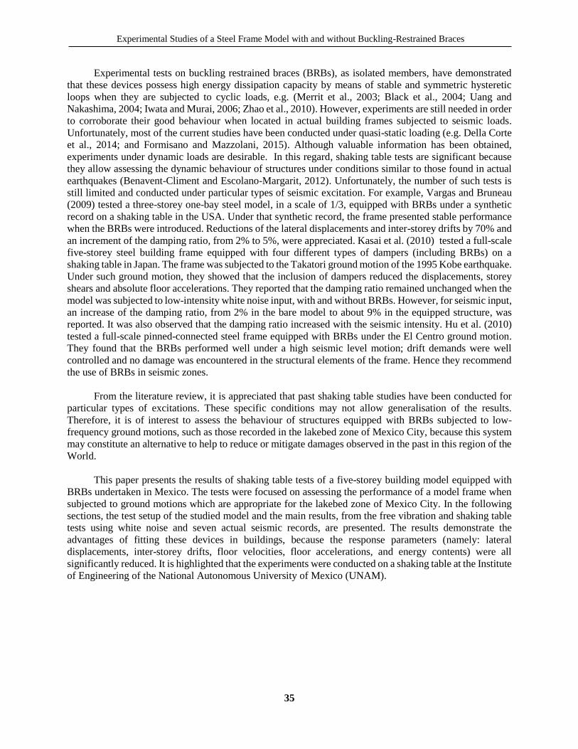
Buckling-restrained braces (BRBs) are a type of passive seismic dissipater and represents one of the
major developments in seismic design in recent years. Although there are several configurations (as
summarised by Xie, 2005), it commonly consists of a rectangular steel core and a case (Figure 1). The core
is weaker in the central zone so that the plastic deformations under cyclic loading are concentrated there.
The case is often made either of a steel tube filled with concrete (e.g. Merrit et al., 2003; and Black et al.,
2004), or all made of steel (e.g. Della Corte et al., 2014; and Formisano and Mazzolani, 2015). The function
of the case is to prevent buckling of the core so that the device has similar capacity in tension and
compression (Figure 1d). An unbounding material is located between the core and the case to avoid direct
interaction. Several enhancements to BRBs have been proposed recently in order to improve their
implementation in practical applications (e.g. Iwata and Murai, 2006; Zhao et al., 2010).
a) Parts
b) Cross-section c) A BRB in a frame d) Behavior under cyclic loads
Figure 1. Buckling-Restrained Braces (BRBs)
Core Case
Core
Steel tube
Unboundingmaterial
Concrete Displ.
Tension
Compression
Traditionalbraces
Experimental Studies of a Steel Frame Model with and without Buckling-Restrained Braces
35
Experimental tests on buckling restrained braces (BRBs), as isolated members, have demonstrated
that these devices possess high energy dissipation capacity by means of stable and symmetric hysteretic
loops when they are subjected to cyclic loads, e.g. (Merrit et al., 2003; Black et al., 2004; Uang and
Nakashima, 2004; Iwata and Murai, 2006; Zhao et al., 2010). However, experiments are still needed in order
to corroborate their good behaviour when located in actual building frames subjected to seismic loads.
Unfortunately, most of the current studies have been conducted under quasi-static loading (e.g. Della Corte
et al., 2014; and Formisano and Mazzolani, 2015). Although valuable information has been obtained,
experiments under dynamic loads are desirable. In this regard, shaking table tests are significant because
they allow assessing the dynamic behaviour of structures under conditions similar to those found in actual
earthquakes (Benavent-Climent and Escolano-Margarit, 2012). Unfortunately, the number of such tests is
still limited and conducted under particular types of seismic excitation. For example, Vargas and Bruneau
(2009) tested a three-storey one-bay steel model, in a scale of 1/3, equipped with BRBs under a synthetic
record on a shaking table in the USA. Under that synthetic record, the frame presented stable performance
when the BRBs were introduced. Reductions of the lateral displacements and inter-storey drifts by 70% and
an increment of the damping ratio, from 2% to 5%, were appreciated. Kasai et al. (2010) tested a full-scale
five-storey steel building frame equipped with four different types of dampers (including BRBs) on a
shaking table in Japan. The frame was subjected to the Takatori ground motion of the 1995 Kobe earthquake.
Under such ground motion, they showed that the inclusion of dampers reduced the displacements, storey
shears and absolute floor accelerations. They reported that the damping ratio remained unchanged when the
model was subjected to low-intensity white noise input, with and without BRBs. However, for seismic input,
an increase of the damping ratio, from 2% in the bare model to about 9% in the equipped structure, was
reported. It was also observed that the damping ratio increased with the seismic intensity. Hu et al. (2010)
tested a full-scale pinned-connected steel frame equipped with BRBs under the El Centro ground motion.
They found that the BRBs performed well under a high seismic level motion; drift demands were well
controlled and no damage was encountered in the structural elements of the frame. Hence they recommend
the use of BRBs in seismic zones.
From the literature review, it is appreciated that past shaking table studies have been conducted for
particular types of excitations. These specific conditions may not allow generalisation of the results.
Therefore, it is of interest to assess the behaviour of structures equipped with BRBs subjected to low-
frequency ground motions, such as those recorded in the lakebed zone of Mexico City, because this system
may constitute an alternative to help to reduce or mitigate damages observed in the past in this region of the
World.
This paper presents the results of shaking table tests of a five-storey building model equipped with
BRBs undertaken in Mexico. The tests were focused on assessing the performance of a model frame when
subjected to ground motions which are appropriate for the lakebed zone of Mexico City. In the following
sections, the test setup of the studied model and the main results, from the free vibration and shaking table
tests using white noise and seven actual seismic records, are presented. The results demonstrate the
advantages of fitting these devices in buildings, because the response parameters (namely: lateral
displacements, inter-storey drifts, floor velocities, floor accelerations, and energy contents) were all
significantly reduced. It is highlighted that the experiments were conducted on a shaking table at the Institute
of Engineering of the National Autonomous University of Mexico (UNAM).
Héctor Guerrero, Tianjian Ji and José A. Escobar
36
TEST SETUP FOR THE FRAME BUILDING MODEL
The model
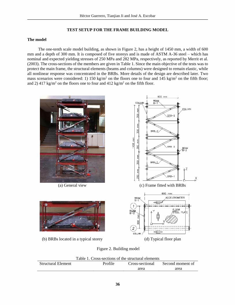
The one-tenth scale model building, as shown in Figure 2, has a height of 1450 mm, a width of 600
mm and a depth of 300 mm. It is composed of five storeys and is made of ASTM A-36 steel – which has
nominal and expected yielding stresses of 250 MPa and 282 MPa, respectively, as reported by Merrit et al.
(2003). The cross-sections of the members are given in Table 1. Since the main objective of the tests was to
protect the main frame, the structural elements (beams and columns) were designed to remain elastic, while
all nonlinear response was concentrated in the BRBs. More details of the design are described later. Two
mass scenarios were considered: 1) 150 kg/m2 on the floors one to four and 145 kg/m2 on the fifth floor;
and 2) 417 kg/m2 on the floors one to four and 412 kg/m2 on the fifth floor.
(a) General view
(c) Frame fitted with BRBs
(b) BRBs located in a typical storey (d) Typical floor plan
Figure 2. Building model
Table 1. Cross-sections of the structural elements
Structural Element Profile Cross-sectional
area
Second moment of
area
Experimental Studies of a Steel Frame Model with and without Buckling-Restrained Braces
37
Columns Rectangular 243.84 mm2 468.17 mm4
Beams B-1 (X direction) Tee 660.67 mm2 207,685 mm4
Beams B-2 (Y direction) Rectangular 303.60 mm2 64,777 mm4
BRBs used in the tests
Due to the scale of the test frame model (1/10), there are no commercially available BRBs. Therefore,
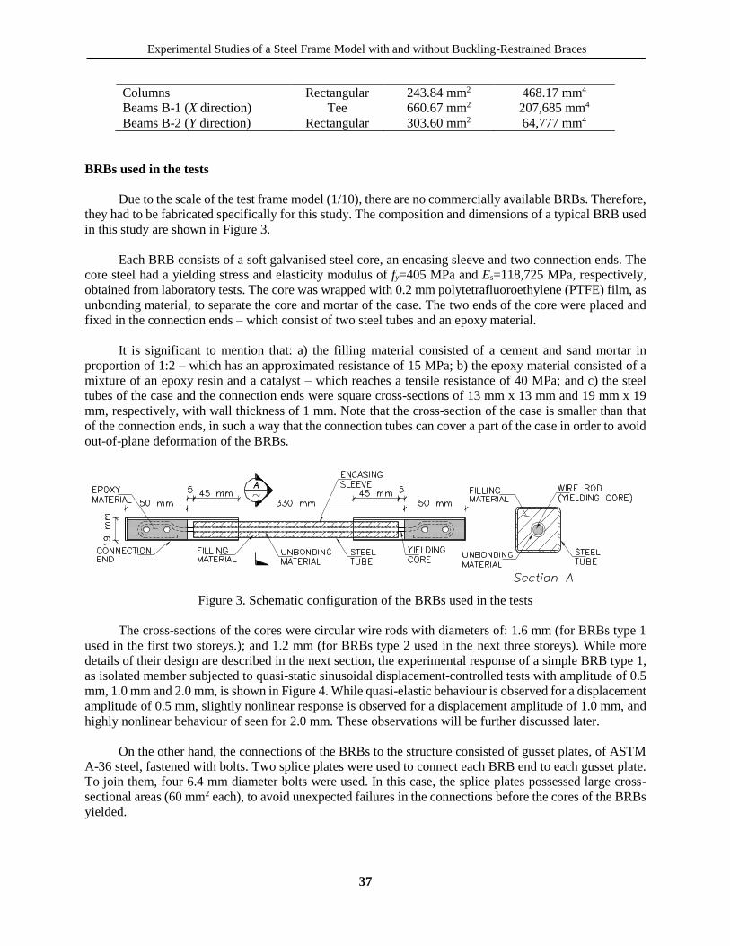
they had to be fabricated specifically for this study. The composition and dimensions of a typical BRB used
in this study are shown in Figure 3.
Each BRB consists of a soft galvanised steel core, an encasing sleeve and two connection ends. The
core steel had a yielding stress and elasticity modulus of fy=405 MPa and Es=118,725 MPa, respectively,
obtained from laboratory tests. The core was wrapped with 0.2 mm polytetrafluoroethylene (PTFE) film, as
unbonding material, to separate the core and mortar of the case. The two ends of the core were placed and
fixed in the connection ends – which consist of two steel tubes and an epoxy material.
It is significant to mention that: a) the filling material consisted of a cement and sand mortar in
proportion of 1:2 – which has an approximated resistance of 15 MPa; b) the epoxy material consisted of a
mixture of an epoxy resin and a catalyst – which reaches a tensile resistance of 40 MPa; and c) the steel
tubes of the case and the connection ends were square cross-sections of 13 mm x 13 mm and 19 mm x 19
mm, respectively, with wall thickness of 1 mm. Note that the cross-section of the case is smaller than that
of the connection ends, in such a way that the connection tubes can cover a part of the case in order to avoid
out-of-plane deformation of the BRBs.
Figure 3. Schematic configuration of the BRBs used in the tests
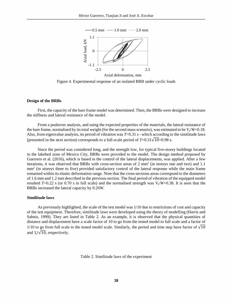
The cross-sections of the cores were circular wire rods with diameters of: 1.6 mm (for BRBs type 1
used in the first two storeys.); and 1.2 mm (for BRBs type 2 used in the next three storeys). While more
details of their design are described in the next section, the experimental response of a simple BRB type 1,
as isolated member subjected to quasi-static sinusoidal displacement-controlled tests with amplitude of 0.5
mm, 1.0 mm and 2.0 mm, is shown in Figure 4. While quasi-elastic behaviour is observed for a displacement
amplitude of 0.5 mm, slightly nonlinear response is observed for a displacement amplitude of 1.0 mm, and
highly nonlinear behaviour of seen for 2.0 mm. These observations will be further discussed later.
On the other hand, the connections of the BRBs to the structure consisted of gusset plates, of ASTM
A-36 steel, fastened with bolts. Two splice plates were used to connect each BRB end to each gusset plate.
To join them, four 6.4 mm diameter bolts were used. In this case, the splice plates possessed large cross-
sectional areas (60 mm2 each), to avoid unexpected failures in the connections before the cores of the BRBs
yielded.
Héctor Guerrero, Tianjian Ji and José A. Escobar
38
Figure 4. Experimental response of an isolated BRB under cyclic loads
Design of the BRBs
First, the capacity of the bare frame model was determined. Then, the BRBs were designed to increase
the stiffness and lateral resistance of the model.
From a pushover analysis, and using the expected properties of the materials, the lateral resistance of
the bare frame, normalised by its total weight (for the second mass scenario), was estimated to be Vy/W=0.18.
Also, from eigenvalue analysis, its period of vibration was T=0.31 s - which according to the similitude laws
(presented in the next section) corresponds to a full-scale period of T=0.31√10=0.98 s.
Since the period was considered long, and the strength low, for typical five-storey buildings located
in the lakebed zone of Mexico City, BRBs were provided to the model. The design method proposed by
Guerrero et al. (2016), which is based in the control of the lateral displacements, was applied. After a few
iterations, it was observed that BRBs with cross-section areas of 2 mm2 (in storeys one and two) and 1.1
mm2 (in storeys three to five) provided satisfactory control of the lateral response while the main frame
remained within its elastic deformation range. Note that the cross-sections areas correspond to the diameters
of 1.6 mm and 1.2 mm described in the previous section. The final period of vibration of the equipped model
resulted T=0.22 s (or 0.70 s in full scale) and the normalised strength was Vy/W=0.38. It is seen that the
BRBs increased the lateral capacity by 0.20W.
Similitude laws
As previously highlighted, the scale of the test model was 1/10 due to restrictions of cost and capacity
of the test equipment. Therefore, similitude laws were developed using the theory of modelling (Harris and
Sabnis, 1999). They are listed in Table 2. As an example, it is observed that the physical quantities of
distance and displacement have a scale factor of 10 to go from the tested model to full scale and a factor of
1/10 to go from full scale to the tested model scale. Similarly, the period and time step have factor of √10
and 1/√10, respectively.
Table 2. Similitude laws of the experiment
-1.1
0
1.1
-2.5 0 2.5
Ax
ial
load
, k
N
Axial deformation, mm
0.5 mm 1.0 mm 2.0 mm

Experimental Studies of a Steel Frame Model with and without Buckling-Restrained Braces
39
Physical property Scale factor (from model to
full-scale)
Scale factor (from full-
scale to model)
Distance 10 1/10
Area 102 1/102
Second moment of area 104 1/104
Mass per area 1 1
Elasticity modulus 1 1
Stress 1 1
Period of vibration √10 1/√10 Time step √10 1/√10 Displacements 10 1/10
Velocities √10 1/√10 Acceleration 1 1
Instrumentation and measured data
Three accelerometers were located on each floor: two in the longer direction (X) and one in the shorter
direction (Y) (Figure 2d). Thus the responses in the X and Y direction and in the torsional direction could be
monitored. Setra 141 accelerometers were used because of their high accuracy, output stability and
measurement range (from static to 3000 Hz). The lateral displacements at each storey were estimated by
double integration of the measured accelerations. To avoid unintended errors during the integration process,
recommendations by Boore and Bommer (2005) were considered. No filtering, filtering between 0.1 and 20
Hz and between 0.5 and 20 Hz were tested. Figure 5a shows the 5%-damped elastic displacement spectra
based on the accelerations recorded at the base of the model in one test. It is observed that none of the band-
pass filters affected the response in the frequency range of interest between 1 Hz and 10 Hz. On the other
hand, Figure 5b shows the transfer functions between the top floor and the base of the model, due to a white
noise input. It shows that the band-pass filter between 0.5 Hz to 20 Hz eliminated the noise at low
frequencies. Therefore, this filter was considered adequate, and errors in the estimation of the lateral
displacements due to filtering may be considered negligible (Hudson, 1979). However, it is not possible to
estimate permanent (or residual) displacements.
a) Displacement spectra b) Transfer functions
Figure 5. Determination of filter cut-offs
Seismic Input
Seven earthquake records were used to test the model (see Table 3). All seven were recorded in the
lakebed zone of Mexico City, which is characterised by very soft soils, and they have dominant periods of
0
2
4
6
8
0.1 1 10 100
Dis
pla
cem
en
t R
esp
onse
, m
m
Frequency, Hz
No filteringfilter 0.1-20 Hzfilter 0.5-20 Hz
0
5
10
15
0.01 0.1 1 10 100
Tra
nsf
er
Fu
ncti
on
s,
cm
/s2
/ cm
/s2
Frequency, Hz
No filteringfilter 0.1-20 Hzfilter 0.5-20 Hz
Héctor Guerrero, Tianjian Ji and José A. Escobar
40
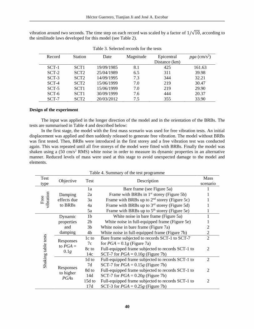
vibration around two seconds. The time step on each record was scaled by a factor of 1/√10, according to
the similitude laws developed for this model (see Table 2).
Table 3. Selected records for the tests
Record Station Date Magnitude Epicentral
Distance (km)
pga (cm/s2)
SCT-1 SCT1 19/09/1985 8.1 425 161.63
SCT-2 SCT2 25/04/1989 6.5 311 39.98
SCT-3 SCT2 14/09/1995 7.3 344 32.21
SCT-4 SCT2 15/06/1999 7.0 219 30.47
SCT-5 SCT1 15/06/1999 7.0 219 29.90
SCT-6 SCT1 30/09/1999 7.6 444 20.37
SCT-7 SCT2 20/03/2012 7.5 355 33.90
Design of the experiment
The input was applied in the longer direction of the model and in the orientation of the BRBs. The
tests are summarised in Table 4 and described below:
In the first stage, the model with the first mass scenario was used for free vibration tests. An initial
displacement was applied and then suddenly released to generate free vibration. The model without BRBs
was first tested. Then, BRBs were introduced in the first storey and a free vibration test was conducted
again. This was repeated until all five storeys of the model were fitted with BRBs. Finally the model was
shaken using a (50 cm/s2 RMS) white noise in order to measure its dynamic properties in an alternative
manner. Reduced levels of mass were used at this stage to avoid unexpected damage to the model and
elements.
Table 4. Summary of the test programme
Test
type Objective Test Description
Mass
scenario
Fre
e
vib
rati
on
Damping
effects due
to BRBs
1a Bare frame (see Figure 5a) 1
2a Frame with BRBs in 1st storey (Figure 5b) 1
3a Frame with BRBs up to 2nd storey (Figure 5c) 1
4a Frame with BRBs up to 3rd storey (Figure 5d) 1
5a Frame with BRBs up to 5th storey (Figure 5e) 1
Sh
akin
g t
able
tes
ts
Dynamic
properties
and
damping
1b White noise in bare frame (Figure 5a) 1
2b White noise in full-equipped frame (Figure 5e) 1
3b White noise in bare frame (Figure 7a) 2
4b White noise in full-equipped frame (Figure 7b) 2
Responses
to PGA =
0.1g
1c to
7c
Bare frame subjected to records SCT-1 to SCT-7
for PGA = 0.1g (Figure 7a)
2
8c to
14c
Full-equipped frame subjected to records SCT-1 to
SCT-7 for PGA = 0.10g (Figure 7b)
2
Responses
to higher
PGAs
1d to
7d
Full-equipped frame subjected to records SCT-1 to
SCT-7 for PGA = 0.15g (Figure 7b)
2
8d to
14d
Full-equipped frame subjected to records SCT-1 to
SCT-7 for PGA = 0.20g (Figure 7b)
2
15d to
17d
Full-equipped frame subjected to records SCT-1 to
SCT-3 for PGA = 0.25g (Figure 7b)
2
Experimental Studies of a Steel Frame Model with and without Buckling-Restrained Braces
41
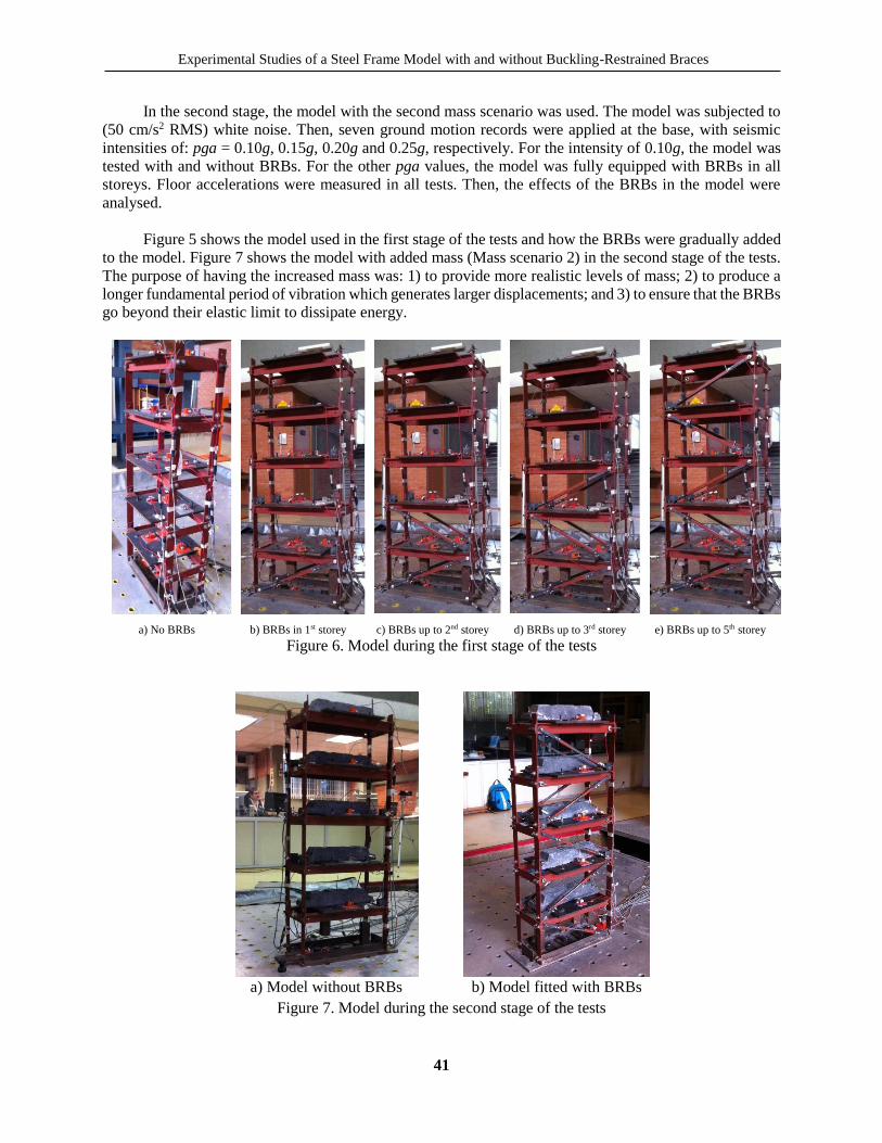
In the second stage, the model with the second mass scenario was used. The model was subjected to
(50 cm/s2 RMS) white noise. Then, seven ground motion records were applied at the base, with seismic
intensities of: pga = 0.10g, 0.15g, 0.20g and 0.25g, respectively. For the intensity of 0.10g, the model was
tested with and without BRBs. For the other pga values, the model was fully equipped with BRBs in all
storeys. Floor accelerations were measured in all tests. Then, the effects of the BRBs in the model were
analysed.
Figure 5 shows the model used in the first stage of the tests and how the BRBs were gradually added
to the model. Figure 7 shows the model with added mass (Mass scenario 2) in the second stage of the tests.
The purpose of having the increased mass was: 1) to provide more realistic levels of mass; 2) to produce a
longer fundamental period of vibration which generates larger displacements; and 3) to ensure that the BRBs
go beyond their elastic limit to dissipate energy.
a) No BRBs b) BRBs in 1st storey c) BRBs up to 2nd storey d) BRBs up to 3rd storey e) BRBs up to 5th storey
Figure 6. Model during the first stage of the tests
a) Model without BRBs b) Model fitted with BRBs
Figure 7. Model during the second stage of the tests
Héctor Guerrero, Tianjian Ji and José A. Escobar
42
EXPERIMENTAL RESULTS
Free vibration tests
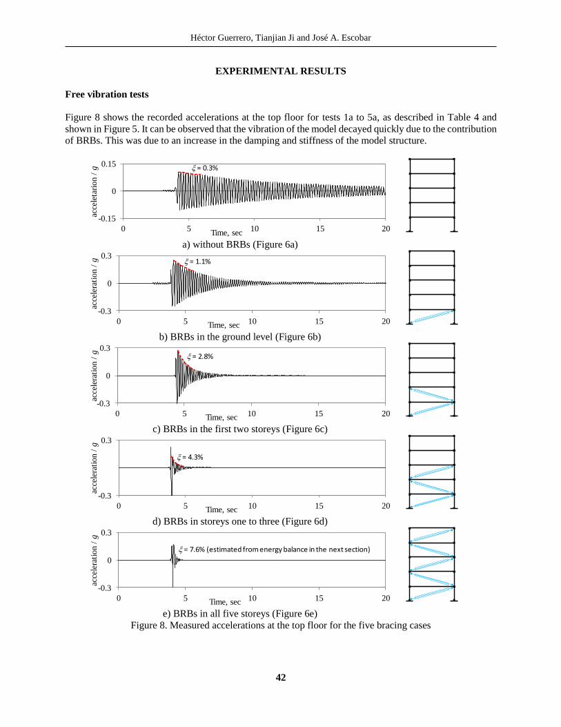
Figure 8 shows the recorded accelerations at the top floor for tests 1a to 5a, as described in Table 4 and
shown in Figure 5. It can be observed that the vibration of the model decayed quickly due to the contribution
of BRBs. This was due to an increase in the damping and stiffness of the model structure.
a) without BRBs (Figure 6a)
b) BRBs in the ground level (Figure 6b)
c) BRBs in the first two storeys (Figure 6c)
d) BRBs in storeys one to three (Figure 6d)
e) BRBs in all five storeys (Figure 6e)
Figure 8. Measured accelerations at the top floor for the five bracing cases
-0.15
0
0.15
0 5 10 15 20
acce
leta
rion
/ g
Time, sec
x = 0.3%
-0.3
0
0.3
0 5 10 15 20
acce
lera
tion
/ g
Time, sec
x = 1.1%
-0.3
0
0.3
0 5 10 15 20
acce
lera
tion
/ g
Time, sec
x = 2.8%
-0.3
0.3
0 5 10 15 20
acce
lera
tion
/ g
Time, sec
x = 4.3%
-0.3
0
0.3
0 5 10 15 20
acce
lera
tio
n /
g
Time, sec
x = 7.6% (estimated from energy balance in the next section)
Experimental Studies of a Steel Frame Model with and without Buckling-Restrained Braces
43
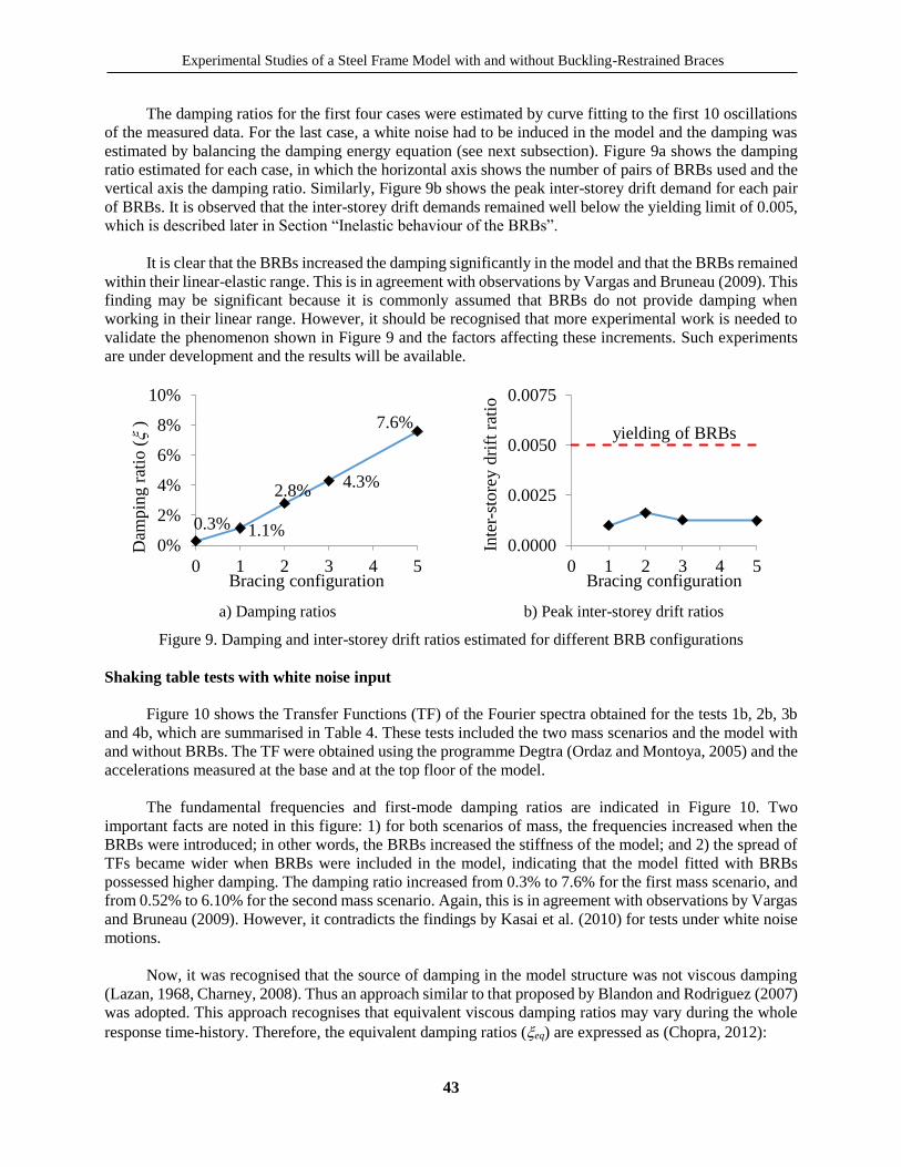
The damping ratios for the first four cases were estimated by curve fitting to the first 10 oscillations
of the measured data. For the last case, a white noise had to be induced in the model and the damping was
estimated by balancing the damping energy equation (see next subsection). Figure 9a shows the damping
ratio estimated for each case, in which the horizontal axis shows the number of pairs of BRBs used and the
vertical axis the damping ratio. Similarly, Figure 9b shows the peak inter-storey drift demand for each pair
of BRBs. It is observed that the inter-storey drift demands remained well below the yielding limit of 0.005,
which is described later in Section “Inelastic behaviour of the BRBs”.
It is clear that the BRBs increased the damping significantly in the model and that the BRBs remained
within their linear-elastic range. This is in agreement with observations by Vargas and Bruneau (2009). This
finding may be significant because it is commonly assumed that BRBs do not provide damping when
working in their linear range. However, it should be recognised that more experimental work is needed to
validate the phenomenon shown in Figure 9 and the factors affecting these increments. Such experiments
are under development and the results will be available.
a) Damping ratios b) Peak inter-storey drift ratios
Figure 9. Damping and inter-storey drift ratios estimated for different BRB configurations
Shaking table tests with white noise input
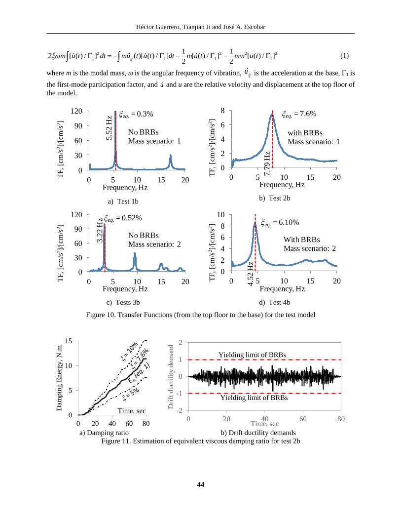
Figure 10 shows the Transfer Functions (TF) of the Fourier spectra obtained for the tests 1b, 2b, 3b
and 4b, which are summarised in Table 4. These tests included the two mass scenarios and the model with
and without BRBs. The TF were obtained using the programme Degtra (Ordaz and Montoya, 2005) and the
accelerations measured at the base and at the top floor of the model.
The fundamental frequencies and first-mode damping ratios are indicated in Figure 10. Two
important facts are noted in this figure: 1) for both scenarios of mass, the frequencies increased when the
BRBs were introduced; in other words, the BRBs increased the stiffness of the model; and 2) the spread of
TFs became wider when BRBs were included in the model, indicating that the model fitted with BRBs
possessed higher damping. The damping ratio increased from 0.3% to 7.6% for the first mass scenario, and
from 0.52% to 6.10% for the second mass scenario. Again, this is in agreement with observations by Vargas
and Bruneau (2009). However, it contradicts the findings by Kasai et al. (2010) for tests under white noise
motions.
Now, it was recognised that the source of damping in the model structure was not viscous damping
(Lazan, 1968, Charney, 2008). Thus an approach similar to that proposed by Blandon and Rodriguez (2007)
was adopted. This approach recognises that equivalent viscous damping ratios may vary during the whole
response time-history. Therefore, the equivalent damping ratios (xeq) are expressed as (Chopra, 2012):
0.3% 1.1%
2.8%4.3%
7.6%
0%
2%
4%
6%
8%
10%
0 1 2 3 4 5
Dam
pin
g r
atio
(x
)
Bracing configuration
0.0000
0.0025
0.0050
0.0075
0 1 2 3 4 5
Inte
r-st
ore
y d
rift
rat
io
Bracing configuration
yielding of BRBs
Héctor Guerrero, Tianjian Ji and José A. Escobar
44
2 2 2 2
1 1 1 1
1 12 [ ( ) / ] ( )[ ( ) / ] [ ( ) / ] [ ( ) / ]
2 2gm u t dt mu t u t dt m u t m u tx (1)
where m is the modal mass, is the angular frequency of vibration, gu is the acceleration at the base, 1 is
the first-mode participation factor, and u and u are the relative velocity and displacement at the top floor of
the model.
a) Test 1b
b) Test 2b
c) Tests 3b
d) Test 4b
Figure 10. Transfer Functions (from the top floor to the base) for the test model
a) Damping ratio b) Drift ductility demands
Figure 11. Estimation of equivalent viscous damping ratio for test 2b
0
30
60
90
120
0 5 10 15 20
TF
, [c
m/s
2]/
[cm
/s2]
Frequency, Hz
No BRBsMass scenario: 1
xeq. = 0.3%5.5
2 H
z
0
2
4
6
8
0 5 10 15 20TF
, [c
m/s
2]/
[cm
/s2]
Frequency, Hz
with BRBsMass scenario: 1
xeq. = 7.6%
7.7
9 H
z0
30
60
90
120
0 5 10 15 20TF
, [c
m/s
2]/
[cm
/s2]
Frequency, Hz
No BRBsMass scenario: 2
xeq. = 0.52%
3.2
2 H
z
0
2
4
6
8
10
0 5 10 15 20TF
, [c
m/s
2]/
[cm
/s2]
Frequency, Hz
With BRBsMass scenario: 2
xeq. = 6.10%
4.5
2 H
z
0
5
10
15
0 20 40 60 80
Dam
pin
g E
ner
gy,
N.m
Time, sec -2
-1
0
1
2
0 20 40 60 80
Dri
ft d
uct
ilit
y d
eman
d
Time, sec
Yielding limit of BRBs
Yielding limit of BRBs
Experimental Studies of a Steel Frame Model with and without Buckling-Restrained Braces
45
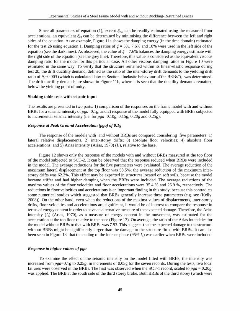
Since all parameters of equation (1), except xeq, can be readily estimated using the measured floor
accelerations, an equivalent xeq can be determined by minimising the difference between the left and right
sides of the equation. As an example, Figure 11a shows the damping energy (in the time domain) estimated
for the test 2b using equation 1. Damping ratios of x = 5%, 7.6% and 10% were used in the left side of the
equation (see the dark lines). As observed, the value of x = 7.6% balances the damping energy estimate with
the right side of the equation (see the grey line). Therefore, this value is considered as the equivalent viscous
damping ratio for the model for this particular case. All other viscous damping ratios in Figure 10 were
estimated in the same way. To verify that the structure remained within its linear-elastic response during
test 2b, the drift ductility demand, defined as the ratio of the inter-storey drift demands to the yielding drift
ratio of y=0.005 (which is calculated later in Section “Inelastic behaviour of the BRBs”), was determined.
The drift ductility demands are shown in Figure 11b, where it is seen that the ductility demands remained
below the yielding point of unity.
Shaking table tests with seismic input
The results are presented in two parts: 1) comparison of the responses on the frame model with and without
BRBs for a seismic intensity of pga=0.1g; and 2) response of the model fully-equipped with BRBs subjected
to incremental seismic intensity (i.e. for pga=0.10g, 0.15g, 0.20g and 0.25g).
Response at Peak Ground Acceleration (pga) of 0.1g
The response of the models with and without BRBs are compared considering five parameters: 1)
lateral relative displacements, 2) inter-storey drifts; 3) absolute floor velocities; 4) absolute floor
accelerations; and 5) Arias intensity (Arias, 1970) (Ia), relative to the base.
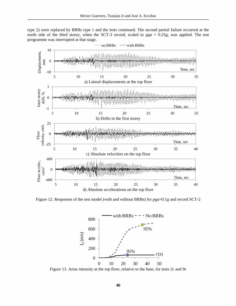
Figure 12 shows only the response of the models with and without BRBs measured at the top floor
of the model subjected to SCT-2. It can be observed that the response reduced when BRBs were included
in the model. The average reductions for the five parameters were evaluated. The average reduction of the
maximum lateral displacement at the top floor was 58.5%; the average reduction of the maximum inter-
storey drifts was 62.2%. This effect may be expected in structures located on soft soils, because the model
became stiffer and had higher damping when the BRBs were included. The average reductions of the
maxima values of the floor velocities and floor accelerations were 35.4 % and 26.9 %, respectively. The
reductions in floor velocities and accelerations is an important finding in this study, because this contradicts
some numerical studies which suggested that BRBs generally increase these parameters (e.g. see (Kelly,
2008)). On the other hand, even when the reductions of the maxima values of displacements, inter-storey
drifts, floor velocities and accelerations are significant, it would be of interest to compare the response in
terms of energy content in order to have an alternative measure of the expected damage. Therefore, the Arias
intensity (Ia) (Arias, 1970), as a measure of energy content in the movement, was estimated for the
acceleration at the top floor relative to the base (Figure 13). On average, the ratio of the Arias intensities for
the model without BRBs to that with BRBs was 7.93. This suggests that the expected damage to the structure
without BRBs might be significantly larger than the damage to the structure fitted with BRBs. It can also
been seen in Figure 13 that the ending of the intense phase (95% Ia) was earlier when BRBs were included.
Response to higher values of pga
To examine the effect of the seismic intensity on the model fitted with BRBs, the intensity was
increased from pga=0.1g to 0.25g, in increments of 0.05g for the seven records. During the tests, two local
failures were observed in the BRBs. The first was observed when the SCT-1 record, scaled to pga = 0.20g,
was applied. The BRB at the south side of the third storey broke. Both BRBs of the third storey (which were
Héctor Guerrero, Tianjian Ji and José A. Escobar
46
type 2) were replaced by BRBs type 1 and the tests continued. The second partial failure occurred at the
north side of the third storey, when the SCT-3 record, scaled to pga = 0.25g, was applied. The test
programme was interrupted at that stage.
a) Lateral displacements at the top floor
b) Drifts in the first storey
c) Absolute velocities on the top floor
d) Absolute accelerations on the top floor
Figure 12. Responses of the test model (with and without BRBs) for pga=0.1g and record SCT-2
Figure 13. Arias intensity at the top floor, relative to the base, for tests 2c and 9c
-10
0
10
5 10 15 20 25 30 35
Dis
pla
cem
ent,
m
m
Time, sec
no BRBs with BRBs
-10
0
10
5 10 15 20 25 30 35
Dis
pla
cem
ent,
m
m
Time, sec
-1
0
1
5 10 15 20 25 30 35
Inte
r-st
ore
y
dri
ft, %
Time, sec
-25
0
25
5 10 15 20 25 30 35 40
Flo
or
vel
oci
ty, c
m/s
Time, sec
-400
0
400
5 10 15 20 25 30 35 40
Flo
or
acce
ler.
, cm
/s2
Time, sec
0
200
400
600
800
0 10 20 30 40 50
I a(m
/s)
with BRBs No BRBs
t (s)
95%
95%
Experimental Studies of a Steel Frame Model with and without Buckling-Restrained Braces
47
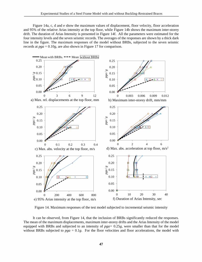
Figure 14a, c, d and e show the maximum values of displacement, floor velocity, floor acceleration
and 95% of the relative Arias intensity at the top floor, while Figure 14b shows the maximum inter-storey
drift. The duration of Arias Intensity is presented in Figure 14f. All the parameters were estimated for the
four intensity levels and the seven seismic records. The averages of the responses are shown by a thick dark
line in the figure. The maximum responses of the model without BRBs, subjected to the seven seismic
records at pga = 0.10g, are also shown in Figure 17 for comparison.
a) Max. rel. displacements at the top floor, mm
b) Maximum inter-storey drift, mm/mm
c) Max. abs. velocity at the top floor, m/s
d) Max. abs. acceleration at top floor, m/s2
e) 95% Arias intensity at the top floor, m/s
f) Duration of Arias Intensity, sec
Figure 14. Maximum responses of the test model subjected to incremental seismic intensity
It can be observed, from Figure 14, that the inclusion of BRBs significantly reduced the responses.
The mean of the maximum displacements, maximum inter-storey drifts and the Arias Intensity of the model
equipped with BRBs and subjected to an intensity of pga= 0.25g, were smaller than that for the model
without BRBs subjected to pga = 0.1g. For the floor velocities and floor accelerations, the model with
0.00
0.05
0.10
0.15
0.20
0.25
0 3 6 9 12
pg
a /
g
Mean with BRBs. Mean without BRBs
0.00
0.05
0.10
0.15
0.20
0.25
0 0.003 0.006 0.009 0.012
pga /
g
0.00
0.05
0.10
0.15
0.20
0.25
0 0.1 0.2 0.3 0.4
pg
a /
g
0.00
0.05
0.10
0.15
0.20
0.25
0 2 4 6
pga
/ g
0.00
0.05
0.10
0.15
0.20
0.25
0 200 400 600 800
pga /
g
0.00
0.05
0.10
0.15
0.20
0.25
0 10 20 30 40
pg
a /
g

Héctor Guerrero, Tianjian Ji and José A. Escobar
48
BRBs can accommodate about 1.5 times more seismic intensity than the model without BRBs. In addition,
by observing the dispersion of the data, it is appreciated that the model with BRBs is less sensitive to the
seismic input than the bare model at the intensity level of pga=0.1g.
Finally, the duration of the intense phase (from 0.05Ia to 0.95Ia), provided in Figure 14f, shows that
the model fitted with BRBs had a much shorter duration of the intense phase. When the model was equipped
with BRBs, the durations of the intense phases of the Arias intensities were almost constant for all four
values of pga and the average duration was less than that on the bare model for pga = 0.10g.
Inelastic behaviour of the BRBs
This section is developed to determine the seismic intensity at which the BRBs reached inelastic
behaviour, i.e. the seismic intensity at which the BRBs started dissipating energy by plastic deformation of
their steel core.
First, the yielding inter-storey drift (y) is estimated and then compared to the maxima demands of
Figure 14b. y is defined by:
1
cos
y y
y
u
h h
(2)
where y is the relative displacement between two consecutive storeys at which yielding of the BRBs
is expected, uy is the BRBs axial deformation at which they yield, is the inclination angle of the BRBs,
and h is the inter-storey height.
By considering the connection ends of the BRBs used in the experiment as infinitively stiff, the
yielding deformation of the BRBs can be estimated as:
y
y y y y
s
fu L L
E (3)
where Ly is the yielding length of the steel core of the BRBs, and fy and Es are the material’s yielding
stress and modulus of elasticity – which were determined experimentally.
Substituting the values of Ly=330 mm (see Figure 3) and the experimental values of fy=405 MPa and
Es=118,725 MPa. The yielding deformation of the BRBs is uy =1.12 mm. This is in agreement with the
results of Figure 4 – where slightly nonlinear behaviour was appreciated for displacement deformation
around 1 mm or below. Substituting uy =1.12 mm in equation (2) the yielding inter-storey drift in the first
storey, where the maxima demands were observed, is:
1.12 1
0.0050.923 250
y
By comparing y = 0.005 with the inter-storey drift demands of Figure 14b, it can be observed that
the BRBs presented linear-elastic behaviour for a seismic intensity of pga=0.10g, while inelastic behaviour
started at an intensity of pga=0.15g.
Experimental Studies of a Steel Frame Model with and without Buckling-Restrained Braces
49
DISCUSSION
The measured results indicate that the model equipped with BRBs reduces the responses and their
record-to-record variability (and hence, uncertainties). In addition, the Arias intensity (as a measure of the
energy contents) showed that the model with BRBs may present significantly less damage than the model
without BRBs.
Increases in damping were observed due to the inclusion of BRBs in the model. The damping
increased from 0.3% to 7.6% for the first mass scenario and from 0.52% to 6.1% for the second mass
scenario. However, it is difficult to quantify the contributions from the BRBs and from the connections
between BRBs and the model. The observed increases of damping are significant and should be considered
in the design process of structures equipped with BRBs. Depending on the design approach, namely force-
based design (FBD) or displacement-based design (DBD), the level of damping provided by BRBs can be
included straightforwardly. For example, in the FBD approach the increase of damping can be considered
by modifying the design spectrum with a correction factor, such as that defined by equation (3.6) of
Eurocode 8 (2004). In the DBD approach, the increased damping ratio can be considered directly in the
estimation of the displacement demands, e.g. in equation (10) by Guerrero et al. (2016) the damping ratio
provided by the BRBs (x2) can be added to the damping ratio provided by the primary structure (x1).
The permanent (or residual) deformations of the model equipped with BRBs were not possible to
measure during the tests. But no permanent deformations were visually identified after each test and after
all the BRBs were removed. This gives an indication of the low permanent deformation of the tested model.
The costs associated with rehabilitation of structures equipped with BRBs may be reduced to replacing the
devices without interruptions to the building functionality; which may be regarded as a cost-effective
solution.
Since the responses of the model equipped with BRBs were significantly improved, it may be thought
that these devices would benefit structures located in the lakebed zone of Mexico City. Including BRBs in
new designs could lead to better performance or lower construction costs. Also existing buildings could be
upgraded to achieve enhanced levels of performance.
CONCLUSIONS
Free vibration and shaking table tests have been carried out on a five-storey model and the results are
summarised in this paper. The following conclusions have been reached:
1. The inclusion of BRBs in the model not only increased the stiffness but also the damping. For the first
and second scenarios of mass, the increases were from x=0.3% to 7.6% and from x=0.52% to 6.10%,
respectively.
2. All the response parameters (and record-to-record variability) were reduced for the model fitted with
BRBs. Using the same pga=0.1g, the average values of the maximum displacement and maximum inter-
storey drift were reduced by 58.5% and 62.2%, respectively. The maximum floor velocities and
maximum floor accelerations were reduced by 35.4 % and 26.9 %, respectively. The Arias Intensity, as
a measure of the energy content, was almost eight times less on the structure with BRBs than on the
structure without BRBs.
3. These reductions suggest that structural and non-structural damage and losses of contents may be
significantly less when BRBs are included in structures located in the lakebed zone of Mexico City.
4. From the tests with incremental seismic intensity, it can be concluded that the model fitted with BRBs
was able to accommodate up to 2.5 times more seismic intensity in terms of lateral displacements, inter-
Héctor Guerrero, Tianjian Ji and José A. Escobar
50
storey drifts and Arias Intensity, and up to 1.5 times more seismic intensity in terms of floor velocity
and floor acceleration.
5. Residual deformations of the model were not visually identifiable before or after all the BRBs were
removed from it.
ACKNOWLEDGEMENTS
The first author recognises the sponsorship provided by CONACyT, SEP and UNAM from Mexico.
REFERENCES
Arias, A (1970), “A Measure of Earthquake Intensity” In: Hansen, R J (ed.) Seismic Design for Nuclear
Power Plants, MIT Press, Cambridge, Massachusetts, USA.
Arroyo, D and M Ordaz (2007), “Hysteretic Energy Demands for SDOF Systems Subjected to Narrow Band
Earthquake Ground Motions. Applications to the Lake Bed Zone of Mexico City”, Journal of
Earthquake Engineering, 11, 147-165. DOI:10.1080/13632460601123131
Benavent-Climent, A and D Escolano-Margarit (2012), “Shaking table tests of structures with hysteretic
dampers: experimental results versus prediction using non-linear static methods”, Bulletin of
Earthquake Engineering, 10, 1857-1883. DOI:10.1007/s10518-012-9375-6
Black, C J, N Makris and I D Aiken (2004), “Component testing, seismic evaluation and characterization
of buckling-restrained braces”, Journal of Structural Engineering, ASCE, 130, 880–894.
DOI:10.1061/(ASCE)0733-9445(2004)130:6(880)
Blandón, J J and M E Rodríguez (2007), “Estudio analítico-experimental y propuesta de diseño sísmico de
sistema de pisos rígidos en edificios”. Serie Investigación y desarrollo, Instituto de Ingeniería -
UNAM.
Bojórquez, E and S E Ruiz (2004), “Strength Reduction Factors for the Valley of Mexico, Considering Low-
Cycle Fatigue Effects”. 13th WCEE. Vancouver, B.C., Canada.
Boore, D M and J J Bommer (2005), “Processing of strong-motion accelerograms: needs, options and
consequences”. Soil Dynamics and Earthquake Engineering, 25, 93-115.
DOI:10.1016/j.soildyn.2004.10.007
Charney, F A (2008), “Unintended Consequences of Modeling Damping in Structures”. Journal of
Structural Engineering, ASCE, 134, 581-590. DOI:10.1061/(ASCE)0733-9445(2008)134:4(581)
Chopra, A K (2012), “Dynamics of Structures: Theory and Applications to Earthquake Engineering”, 4th
Edition, Prentice Hall, Englewood Cliffs, New Jersey.
Della Corte, M, D'aniello R and Landolfo (2015), “Field testing of all-steel buckling-restrained braces
applied to a damaged reinforced concrete building”, Journal of Structural Engineering ASCE, 141
(1), p D4014004. DOI:10.1061/(ASCE)ST.1943-541X.0001080
Eurocode 8 (2004), “Eurocode 8: Design of structures for earthquake resistance. Part 1: General rules,
seismic actions and rules for buildings”, Ref. No. EN 1998-1:2004: E.
Formisano, A and F M Mazzolani (2015), “On the selection by MCDM methods of the optimal system for
seismic retrofitting and vertical addition of existing buildings”, Computers and Structures, 149, pp.
1-13. DOI:10.1016/j.compstruc.2015.06.016
Experimental Studies of a Steel Frame Model with and without Buckling-Restrained Braces
51
Guerrero, H, T Ji, A Teran-Gilmore and J A Escobar (2016), “A method for preliminary seismic design and
assessment of low-rise structures protected with Buckling-Restrained Braces”. Engineering
Structures. 123, pp. 141–154. DOI:10.1016/j.engstruct.2016.05.015
Harris, H G and G M Sabnis (1999), “Structural modelling and experimental techniques”, Second Edition,
CRC Press.
Hu, D, G Li, F Sun, D Wang, M Rui, L Li and J He (2010), “Full-scale shaking table tests on a hinge-
connected steel frame with buckling restrained braces”. China Civil Engineering Journal, 43, 520-
525.
Hudson, D E (1979), “Reading and Interpreting strong motion accelerograms”, Earthquake Engineering
Research Institute, Berkeley, CA.
Iwata, M and M Murai (2006), “Buckling-restrained brace using steel mortar planks; performance
evaluation as a hysteretic damper”, Earthquake Engineering and Structural Dynamics, 35, 1807–
1826. DOI:10.1002/eqe.608
Kasai, K, H Ito, Y Ooki, T Hikino, K Kajiwara, S Motoyui, H Ozaki and M Ishii (2010), “Full-Scale Shake
Table Tests of 5-Story Steel Building with various Dampers”. Joint Conference 7CUEE & 5ICEE,
Tokyo Institute of Technology, Tokyo, Japan.
Kelly, T E (2008), “Improving Seismic Performance: Add Stiffness or Damping?”, Bulletin of the New
Zealand Society for Earthquake Engineering, 41, 24-30.
Lazan, B J (1968), “Damping of materials and members in structural mechanics”, Pergamon Press, Oxford,
UK.
Merrit, S, C M Uang, and G Benzoni (2003), “Subassemblage testing of Corebrace Buckling-Restrained
Braces”, Report No. TR-2003/04, University of California, San Diego, La Jolla, CA.
Montiel, M and A Teran-Gilmore (2011), “Comparative reliability of two 24-story braced buildings:
traditional versus innovative”, The structural design of tall and special buildings, 22 (8), 635-654.
DOI:10.1002/tal.716
Ordaz, M and C Montoya (2005), “Degtra v5.1.0”, Institute of Engineering, UNAM, Mexico City, Mexico.
Reinoso, E and M Jaimes (2005), “Accelerograms for building design for hard soil in Mexico City”,
Earthquake Resistant Engineering Structures, 81, 23-32. DOI:10.2495/ERES050031
Rosenblueth, E, F M Sanchez-Sesma, y S K Singh (1988), “Design spectra for Mexico's Federal District”,
9th WCEE, Tokyo, Japan.
Teran-Gilmore, A and N Bahena (2008), “Cumulative ductility spectra for seismic design of ductile
structures subjected to long duration motions: Concept and theoretical background”, Journal of
Earthquake Engineering, 12, 152-172. DOI:10.1080/13632460701364486
Uang, C M and M Nakashima (2004), “Steel Buckling-Restrained Braced Frames”. In: Bozorgnia, Y & V
V Bertero (editors) Earthquake Engineering from Engineering Seismology to Performance-Based
Engineering. CRC Press.
Xie (2005). “State of the art of buckling-restrained braces in Asia”, Journal of Constructional Steel
Research, 61 (6), 727–748. DOI:10.1016/j.jcsr.2004.11.005
Vargas, R and M Bruneau (2009), “Experimental Response of Buildings Designed with Metallic Structural
Fuses. II”, Journal of Structural Engineering-ASCE, 135, 394-403. DOI:10.1061/(ASCE)0733-
9445(2009)135:4(394)

Héctor Guerrero, Tianjian Ji and José A. Escobar
52
Zhao, J, B Wu and J Ou (2011), “A novel type of angle steel buckling-restrained brace: cyclic behaviour
and failure mechanism”, Earthquake Engineering and Structural Dynamics, 40, 1083–1102.
DOI:10.1002/eqe.1071