Experimental Optimization of Electron Beams for...
15
Prach Boonpornprasert DPG-Frühjahrstagung 2017 TU Dresden, Dresden 22.03.2017 Experimental Optimization of Electron Beams for Generating THz CTR and CDR with PITZ Outline ► Introduction ► Optimization of Electron Beams ► Calculations of CTR/CDR Pulse Energy ► Summary & Outlook
Transcript of Experimental Optimization of Electron Beams for...

Prach Boonpornprasert
DPG-Frühjahrstagung 2017
TU Dresden, Dresden
22.03.2017
Experimental Optimization of Electron Beams for
Generating THz CTR and CDR with PITZ
Outline
► Introduction
► Optimization of Electron Beams
► Calculations of CTR/CDR
Pulse Energy
► Summary & Outlook

Experimental Optimization of Electron Beams for Generating THz CTR and CDR with PITZ
Prach Boonpornprasert | DPG-Frühjahrstagung 2017 | 22.3.2017 | Page 2
PITZ Facility
Photocathode
RF Gun Booster (Linac)
Deflecting Cavity
0 m
PITZ Beamline Layout
~21.7 m
► The Photo-Injector Test facility at DESY
Zeuthen site (PITZ).
► Develop, study and optimize high
brightness electron sources for linac-
based FELs.
► Working closely with FLASH and the
European XFEL.
► 2 UV photocathode laser systems
■ Cylindrical pulse shape
(Gaussian, flat-top, comb-like)
■ 3D-ellipsoidal pulse shape
Important Parameters
Beamline length ~22 m
Cathode laser pulse
duration
few ps to ~22 ps
(FWHM)
Electron bunch charge sub pC to > 5 nC
Maximum electron
beam momentum ~24 MeV/c
Quadrupole magnet
Dipole magnet
Screen
~7 MeV/c ~22 MeV/c
HEDA2
Adjustable by using laser pulse shaper

Experimental Optimization of Electron Beams for Generating THz CTR and CDR with PITZ
Prach Boonpornprasert | DPG-Frühjahrstagung 2017 | 22.3.2017 | Page 3
Motivations for Studies of IR/THz Production at PITZ
IR/THz sources
• Conventional laser
• Accelerator based
Pump & Probe
experiment
X-ray
IR/THz
Requirements of the IR/THz Pulses
Same time structure and repetition rate
as those of the X-ray pulses
(XFEL 27000 pulses / sec)
Possible to have precise synchronization
with each of the X-ray pulses
High stability (intensity and phase)
High (various) pulse energy (µJ - mJ)
Wide wavelength tunability:
from 15 µm (20THz) to 3 mm (0.1 THz)
Variety of temporal and spectral patterns
Variety of polarizations
PITZ is an ideal facility for
the development of a prototype of
such accelerator based IR/THz source
Strengths
Over a decade of experience in high brightness photo
injector research and development.
PITZ has same type of electron source as EXFEL
same time structure of radiation pulse merit for precise
synchronization.
The site of a PITZ-like setup is small enough to fit in the
experimental hall for the EXFEL users. short IR/THz
transport
Born to be a test facility, the beam time and the
accelerator are adaptable to new research ideas and
proposals.
3 methods of radiation production have been studied.
Single-pass FEL SASE FEL for λrad ≤ 100 µm (f ≥ 3 THz)
Coherent Transition Radiation(CTR) for λrad ≥ 100 µm (f ≤ 3 THz)
Coherent Diffraction Radiation(CDR) for λrad ≥ 100 µm (f ≤ 3 THz)
Progresses on CTR and CDR studies
are presented in this presentation.
Experimental Optimization of Electron Beams for Generating THz CTR and CDR with PITZ
Prach Boonpornprasert | DPG-Frühjahrstagung 2017 | 22.3.2017 | Page 4
CTR and CDR
E-beam
CTR radiator
𝜃
Backward
transition
radiation
𝜃
E-beam
CDR radiator
Backward
diffraction
radiation
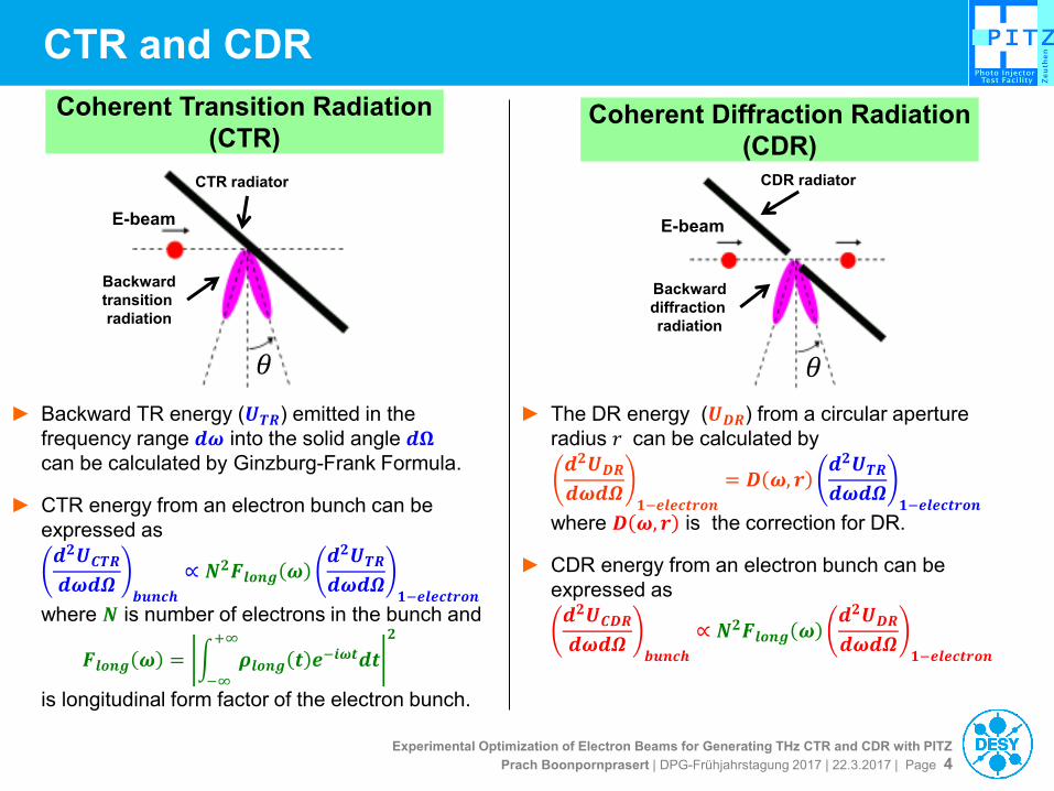
Coherent Transition Radiation
(CTR) Coherent Diffraction Radiation
(CDR)
► Backward TR energy (𝑼𝑻𝑹) emitted in the
frequency range 𝒅𝝎 into the solid angle 𝒅𝛀
can be calculated by Ginzburg-Frank Formula.
► CTR energy from an electron bunch can be
expressed as
𝒅𝟐𝑼𝑪𝑻𝑹𝒅𝝎𝒅𝜴
𝒃𝒖𝒏𝒄𝒉
∝ 𝑵𝟐𝑭𝒍𝒐𝒏𝒈 𝝎𝒅𝟐𝑼𝑻𝑹𝒅𝝎𝒅𝜴
𝟏−𝒆𝒍𝒆𝒄𝒕𝒓𝒐𝒏
where 𝑵 is number of electrons in the bunch and
𝑭𝒍𝒐𝒏𝒈 𝝎 = 𝝆𝒍𝒐𝒏𝒈 𝒕 𝒆−𝒊𝝎𝒕𝒅𝒕
+∞
−∞
𝟐
is longitudinal form factor of the electron bunch.
► The DR energy (𝑼𝑫𝑹) from a circular aperture
radius 𝑟 can be calculated by
𝒅𝟐𝑼𝑫𝑹𝒅𝝎𝒅𝜴
𝟏−𝒆𝒍𝒆𝒄𝒕𝒓𝒐𝒏
= 𝑫 𝝎, 𝒓𝒅𝟐𝑼𝑻𝑹𝒅𝝎𝒅𝜴
𝟏−𝒆𝒍𝒆𝒄𝒕𝒓𝒐𝒏
where 𝑫 𝝎,𝒓 is the correction for DR.
► CDR energy from an electron bunch can be
expressed as
𝒅𝟐𝑼𝑪𝑫𝑹𝒅𝝎𝒅𝜴
𝒃𝒖𝒏𝒄𝒉
∝ 𝑵𝟐𝑭𝒍𝒐𝒏𝒈 𝝎𝒅𝟐𝑼𝑫𝑹𝒅𝝎𝒅𝜴
𝟏−𝒆𝒍𝒆𝒄𝒕𝒓𝒐𝒏

Experimental Optimization of Electron Beams for Generating THz CTR and CDR with PITZ
Prach Boonpornprasert | DPG-Frühjahrstagung 2017 | 22.3.2017 | Page 5
Optimization of Electron Beams
Machine Parameters
Laser diameter on the cathode 2.0, 2.5 mm
Peak E-field in gun 60 MV/m
Peak E-field in booster 17.2 MV/m
Gun phase* 0 degree
Booster phase* 0 to -60 degree
*w.r.t. Maximum Mean Momentum Gain phase
Short Gaussian Beam Optimization
► Illuminated the cathode with a Gaussian
laser pulse with temporal length of ~2.4 ps
FWHM.
► Velocity bunching Went off-crest
booster phase for lower momentum at the
head and higher momentum at the tail of the
electron bunch.
► Measured the longitudinal profile by using
the deflecting cavity,
► Experiments were done with bunch charges
of 20 pC, 100 pC and 250 pC.
Comb-like Beam Optimization
► Illuminated the cathode with a comb-like
laser pulse. In this experiments, the laser
pulse shaper was adjusted for a comb-like
laser pulse with 6 teeth.
► Also went off-crest booster phase for
velocity bunching.
► Measured the longitudinal profile by using
the deflecting cavity,
► Experiments were done with bunch charges
of 100 pC, 250 pC and 500 pC.
Corresponding
<Pz> ~ 22 to 15 MeV/c
Experimental Optimization of Electron Beams for Generating THz CTR and CDR with PITZ
Prach Boonpornprasert | DPG-Frühjahrstagung 2017 | 22.3.2017 | Page 6
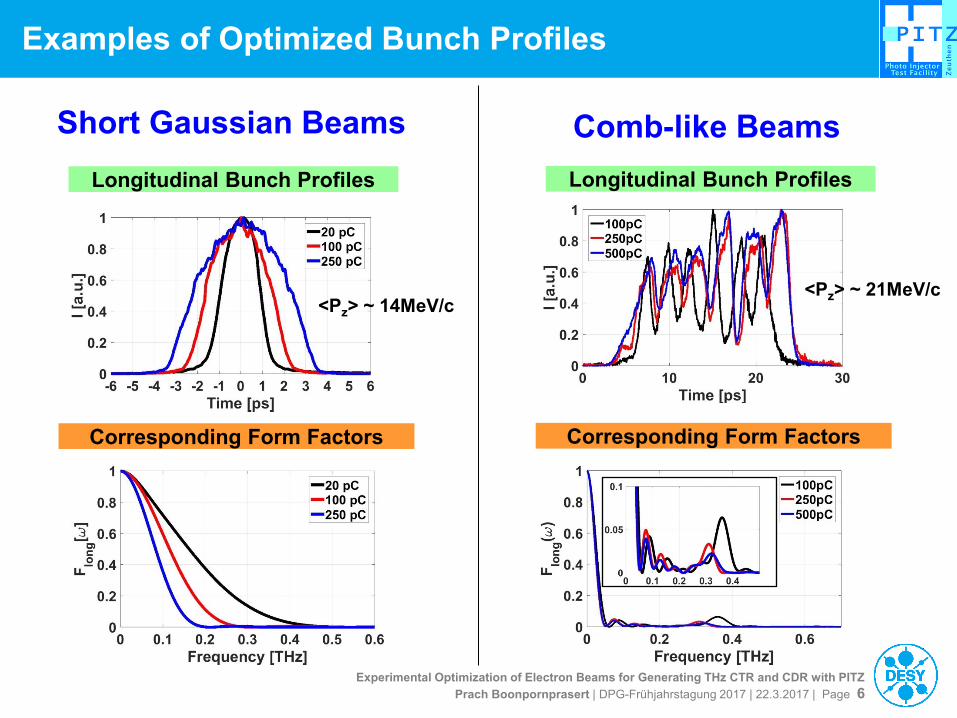
Examples of Optimized Bunch Profiles
Longitudinal Bunch Profiles
Corresponding Form Factors
Short Gaussian Beams Comb-like Beams
Longitudinal Bunch Profiles
Corresponding Form Factors
<Pz> ~ 14MeV/c <Pz> ~ 21MeV/c

Experimental Optimization of Electron Beams for Generating THz CTR and CDR with PITZ
Prach Boonpornprasert | DPG-Frühjahrstagung 2017 | 22.3.2017 | Page 7
Calculations of CTR/CDR Pulse Energy
Radiation Pulse Energy vs Ω vs f
Short Gaussian beam, 250 pC
Comb-like beam, 250 pC
CTR
CTR
CDR
CDR
CTR
CDR
Short Gaussian beam
Comb-like beam
Total Radiation Pulse Energy

Experimental Optimization of Electron Beams for Generating THz CTR and CDR with PITZ
Prach Boonpornprasert | DPG-Frühjahrstagung 2017 | 22.3.2017 | Page 8
Design of the CTR/CDR station
P = off-axis parabolic mirror
F = flat mirror
► The station is placed ~13 m downstream
from the cathode.
► Acceptance angle from the radiator to
the viewport is 0.4 rad.
► The viewport is made of z-cut crystal
quartz.
► THz radiation diagnostics system is
placed in the tunnel, normal room
environment.
► The system will be used to measure:
■ Radiation energy/power
■ Radiation spatial profile
■ Radiation polarization
■ Radiation spectrum (Michaelson
interferometer)
► The detectors is pyroelectric detector. Acknowledgement: G.Koss, S.Philipp
Experimental Optimization of Electron Beams for Generating THz CTR and CDR with PITZ
Prach Boonpornprasert | DPG-Frühjahrstagung 2017 | 22.3.2017 | Page 9
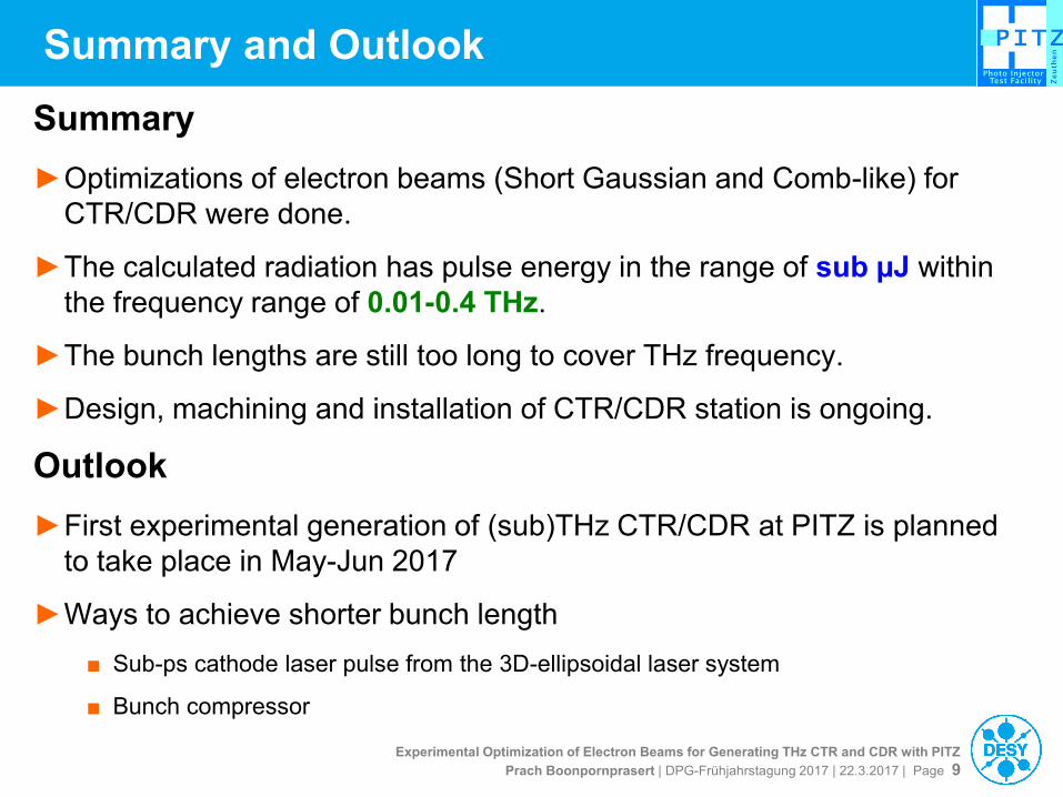
Summary and Outlook
Summary
►Optimizations of electron beams (Short Gaussian and Comb-like) for
CTR/CDR were done.
►The calculated radiation has pulse energy in the range of sub µJ within
the frequency range of 0.01-0.4 THz.
►The bunch lengths are still too long to cover THz frequency.
►Design, machining and installation of CTR/CDR station is ongoing.
Outlook
►First experimental generation of (sub)THz CTR/CDR at PITZ is planned
to take place in May-Jun 2017
►Ways to achieve shorter bunch length
■ Sub-ps cathode laser pulse from the 3D-ellipsoidal laser system
■ Bunch compressor

Experimental Optimization of Electron Beams for Generating THz CTR and CDR with PITZ
Prach Boonpornprasert | DPG-Frühjahrstagung 2017 | 22.3.2017 | Page 10
Backup Slides

Experimental Optimization of Electron Beams for Generating THz CTR and CDR with PITZ
Prach Boonpornprasert | DPG-Frühjahrstagung 2017 | 22.3.2017 | Page 11
Experiments of Velocity Bunching

Experimental Optimization of Electron Beams for Generating THz CTR and CDR with PITZ
Prach Boonpornprasert | DPG-Frühjahrstagung 2017 | 22.3.2017 | Page 12
Comb Beams: Profiles and Form Factors
Fo
rm f
acto
r F
orm
fa
cto
r F
orm
fa
cto
r
FFT
FFT
FFT

Experimental Optimization of Electron Beams for Generating THz CTR and CDR with PITZ
Prach Boonpornprasert | DPG-Frühjahrstagung 2017 | 22.3.2017 | Page 13
Photo Injector: RF-Gun
RFgun:
L-band (1.3 GHz)
nc (copper)
standing wave
1½-cell cavity
Main solenoid,
Bz_peak~0.2T
Bucking solenoid
Photo cathode
(Cs2Te)
QE~0.5-5%
Coaxial RF
coupler
Cathode laser
262nm
20ps (FWHM)
Vacuum
mirror
Electron bunch
<1 pC – 5 nC,
~5-7MeV
UHV
RF gun
• L-band 1.6-cell copper cavity
• Cs2Te photocathode (QE~5-10%)
• Dry ice cleaning low dark current (<100uA@6MW)
• LLRF control for amplitude and phase stability
• Solenoid for emittance compensation

Experimental Optimization of Electron Beams for Generating THz CTR and CDR with PITZ
Prach Boonpornprasert | DPG-Frühjahrstagung 2017 | 22.3.2017 | Page 14
Variation of the pulse shape by using a single different
Lyot filter (UV, measured with OSS)
Edges of the flat-top pulses are slightly shorter than
FWHM of the Gaussian pulse (measured without shaper)
“Smoothening” of the Modulations in the flat-top
region of the pulse
Lyot: 6 mm YLF Lyot: 4 mm YVO4 no Lyot filter
FWHM
= 2.5 ps
FWHM
= 4 ps
FWHM
= 7 ps
FWHM
~ 16 ps
edges ~ 2ps edges ~ 3ps
2 4 ps
2 5 ps 2 5 ps 2 5 ps 2 5 ps
2 5 ps 2 5 ps 2 5 ps 2 5 ps
with
shaper
(13
crystals)
without
shaper
Lyot: 16 mm YLF
~ 2 3 ps
edges ~ 6 ps
~ 19 ps
~ 14 ps
I. Will, G. Klemz „Increasing the flexibility in pulse shape of a Yb:YAG
photocathode laser” 20.06.2009
V
Laser temporal profile for high TR PWA experiment
Experimental Optimization of Electron Beams for Generating THz CTR and CDR with PITZ
Prach Boonpornprasert | DPG-Frühjahrstagung 2017 | 22.3.2017 | Page 15
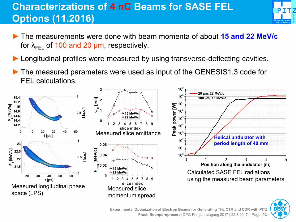
Characterizations of 4 nC Beams for SASE FEL
Options (11.2016)
Measured slice emittance
Calculated SASE FEL radiations
using the measured beam parameters
Measured longitudinal phase
space (LPS) Measured slice
momentum spread
Helical undulator with
period length of 40 mm
<Pz>~15MeV/c
<Pz>~22MeV/c
► The measurements were done with beam momenta of about 15 and 22 MeV/c
for λFEL of 100 and 20 µm, respectively.
► Longitudinal profiles were measured by using transverse-deflecting cavities.
► The measured parameters were used as input of the GENESIS1.3 code for
FEL calculations.