Experimental investigation of structural steel beams ...
15
Manuscript submitted to Engineering Structures March 22, 2020 Experimental investigation of structural steel beams subjected to localized fire Selvarajah Ramesh, Lisa Choe, Chao Zhang * National Institute of Standards and Technology, 100 Bureau Drive, Gaithersburg, MD 20899-1070, USA Abstract This paper presents an experimental behavior of unprotected W16 × 26 steel beams subjected to localized fire. Beam specimens were either simply supported or connected to steel columns via all bolted double angle connections. Two test fires, steady or transient heating, were produced using a natural gas fueled burner located below the center of the beams. Thermal and structural responses of the steel beams as well as the heat release rate and applied forces were measured. The tests showed that all specimens failed by lateral-torsional buckling regardless of fire loading and end support conditions. The results highlight that the heating conditions and end restraints influence the behavior of steel beams under localized fire. The experimental results presented can be used for validation of predictive models in order to improve deign methods for localized fire conditions. Keywords: Experimental investigation; localized fire; steel beam; thermal restraint; lateral-torsional buckling; failure temperature. 1. Introduction Fires in the open or in large enclosures are characterized as localized fires, in which the gas temperatures are spatially non-uniform [1]. The effect of localized fire on structures was studied in the past. Hasemi et al. [2] conducted a series of tests to study the heating mechanism of ceiling/beam system exposed to localized fire. Propane gas fuel was used to produce steady-state fires. The heat release rates (HRRs) were calculated from the volume of flowing gas with the assumption of complete combustion. Heat flux gauges were used to measure the incident heat flux along the ceiling/beam at different distances away from the fire centerline. Based on the test data, a model was developed to calculate the heat flux to the ceiling from flame impingement from a localized fire [3], which is adopted in the Eurocode 1 [4]. In the SFPE handbook [5], empirical correlations are provided to calculate the heat fluxes to different parts of I-shaped ceiling steel beam from localized fire. Zhao and Kruppa [6] reported fire tests performed on a real car park made of steel columns and steel beams connected to composite slabs, in which cars were burned under the structure. Thermocouples were used to measure the gas and steel temperatures. Deflections of the steel beams were also measured. Sandstrom et al. [7] reported test data on steel truss exposed to localized fires. Heptane pool fires were used and the HRRs were calculated from mean value of tabulated fuel burning properties. Gas * Corresponding author. E-mail address: [email protected] (C. Zhang)
Transcript of Experimental investigation of structural steel beams ...
Manuscript submitted to Engineering Structures March 22, 2020
Experimental investigation of structural steel beams subjected to localized fire
Selvarajah Ramesh, Lisa Choe, Chao Zhang*
National Institute of Standards and Technology, 100 Bureau Drive, Gaithersburg, MD 20899-1070, USA
Abstract
This paper presents an experimental behavior of unprotected W16 × 26 steel beams subjected to localized fire. Beam specimens were either simply supported or connected to steel columns via all bolted double angle connections. Two test fires, steady or transient heating, were produced using a natural gas fueled burner located below the center of the beams. Thermal and structural responses of the steel beams as well as the heat release rate and applied forces were measured. The tests showed that all specimens failed by lateral-torsional buckling regardless of fire loading and end support conditions. The results highlight that the heating conditions and end restraints influence the behavior of steel beams under localized fire. The experimental results presented can be used for validation of predictive models in order to improve deign methods for localized fire conditions. Keywords: Experimental investigation; localized fire; steel beam; thermal restraint; lateral-torsional buckling; failure temperature.
1. Introduction
Fires in the open or in large enclosures are characterized as localized fires, in which the gas temperatures are spatially non-uniform [1]. The effect of localized fire on structures was studied in the past. Hasemi et al. [2] conducted a series of tests to study the heating mechanism of ceiling/beam system exposed to localized fire. Propane gas fuel was used to produce steady-state fires. The heat release rates (HRRs) were calculated from the volume of flowing gas with the assumption of complete combustion. Heat flux gauges were used to measure the incident heat flux along the ceiling/beam at different distances away from the fire centerline. Based on the test data, a model was developed to calculate the heat flux to the ceiling from flame impingement from a localized fire [3], which is adopted in the Eurocode 1 [4]. In the SFPE handbook [5], empirical correlations are provided to calculate the heat fluxes to different parts of I-shaped ceiling steel beam from localized fire. Zhao and Kruppa [6] reported fire tests performed on a real car park made of steel columns and steel beams connected to composite slabs, in which cars were burned under the structure. Thermocouples were used to measure the gas and steel temperatures. Deflections of the steel beams were also measured. Sandstrom et al. [7] reported test data on steel truss exposed to localized fires. Heptane pool fires were used and the HRRs were calculated from mean value of tabulated fuel burning properties. Gas
* Corresponding author. E-mail address: [email protected] (C. Zhang)
2
and steel temperatures were measured by thermocouples, and plate thermometers were used to measure the adiabatic surface temperatures. Linear position transducers were used to measure the vertical and horizontal displacements. Ferraz et al. [8] reported experimental studies on thermal response of hollow steel columns exposed to localized fires. Diesel pool fires were used and the HRRs were calculated using an empirical equation which is based on burning rate or mass loss rate of the fuel and assuming complete combustion. Type K wire and probe thermocouples were used to measure the steel and gas temperatures. Tondini and Franssen [9] reported test data on hydrocarbon localized fires with and without engulfed vertical steel members. Heptane pool fires and diesel pool fires were used and the HRRs were calculated from the fuel flow rate using the fuel properties provided by the supplier or from literature. These studies seldom experimentally measured the HRR of a fire, while HRR is an important parameter in the fire modeling [10]. Further, numerical studies [11-14] show that structures in a localized fire might have failure models different from those exposed to enclosed fires. Therefore, localized fire tests on structures with accurate HRR measurement are essentially needed for model validation and developing rational methods for fire safety design of structures with large enclosure.
The National Institute of Standards and Technology (NIST) conducted a series of localized fire tests on 6 m long steel beams in the National Fire Research Laboratory (NFRL) [15]. This paper focuses on the experimental results as well as the effect of heating conditions and end restraints on the behavior of steel beams subjected to localized heating. The design of a test fire and numerical study are presented in the companion papers [16-17]. Details of experimental design and data sets are available in Choe et al. [18].
2. Experimental design
2.1. Test matrix Table 1 gives the test matrix. All specimens were 6.2 m long and had W16 × 26 sections. Specimen 1 was tested at ambient temperature to measure the ambient flexural capacity and to commission the structural loading setup. Specimen 2 and Specimen 3 were used to compare the effect of the loading sequence. Specimen 2 was loaded to failure under steady heating; Specimen 3 was heated to failure while the mechanical load was maintained. Specimen 4 had double angle connections at the ends and was tested under a transient fire.
Table 1. Test matrix for the laboratory experiments Specimen Test No.
in [18] End-support condition Loading protocol
Specimen 1 6 Simple support Structural load Specimen 2 7 Simple support Steady-state fire + Structural load Specimen 3 8 Simple support Transient fire + Structural load Specimen 4 9 Double-angle connection Transient fire + Structural load
3
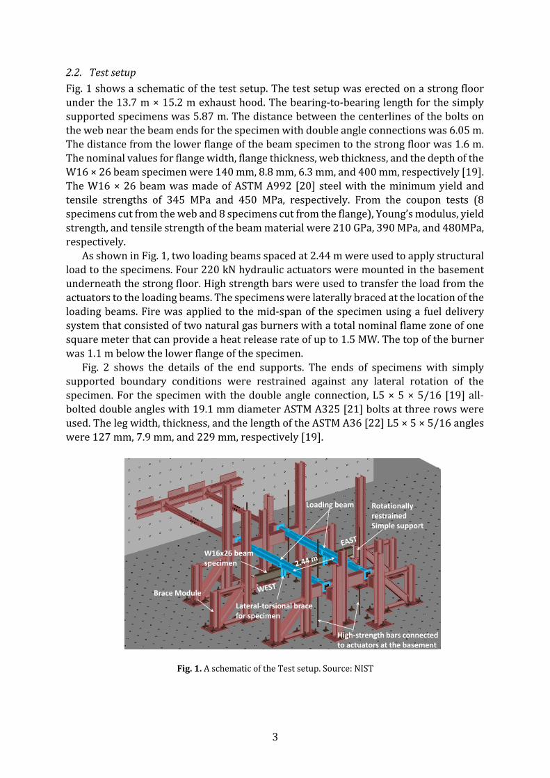
2.2. Test setup Fig. 1 shows a schematic of the test setup. The test setup was erected on a strong floor under the 13.7 m × 15.2 m exhaust hood. The bearing-to-bearing length for the simply supported specimens was 5.87 m. The distance between the centerlines of the bolts on the web near the beam ends for the specimen with double angle connections was 6.05 m. The distance from the lower flange of the beam specimen to the strong floor was 1.6 m. The nominal values for flange width, flange thickness, web thickness, and the depth of the W16 × 26 beam specimen were 140 mm, 8.8 mm, 6.3 mm, and 400 mm, respectively [19]. The W16 × 26 beam was made of ASTM A992 [20] steel with the minimum yield and tensile strengths of 345 MPa and 450 MPa, respectively. From the coupon tests (8 specimens cut from the web and 8 specimens cut from the flange), Young’s modulus, yield strength, and tensile strength of the beam material were 210 GPa, 390 MPa, and 480MPa, respectively.
As shown in Fig. 1, two loading beams spaced at 2.44 m were used to apply structural load to the specimens. Four 220 kN hydraulic actuators were mounted in the basement underneath the strong floor. High strength bars were used to transfer the load from the actuators to the loading beams. The specimens were laterally braced at the location of the loading beams. Fire was applied to the mid-span of the specimen using a fuel delivery system that consisted of two natural gas burners with a total nominal flame zone of one square meter that can provide a heat release rate of up to 1.5 MW. The top of the burner was 1.1 m below the lower flange of the specimen.
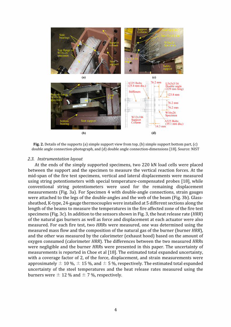
Fig. 2 shows the details of the end supports. The ends of specimens with simply supported boundary conditions were restrained against any lateral rotation of the specimen. For the specimen with the double angle connection, L5 × 5 × 5/16 [19] all-bolted double angles with 19.1 mm diameter ASTM A325 [21] bolts at three rows were used. The leg width, thickness, and the length of the ASTM A36 [22] L5 × 5 × 5/16 angles were 127 mm, 7.9 mm, and 229 mm, respectively [19].
Fig. 1. A schematic of the Test setup. Source: NIST
Loading beam
W16x26 beamspecimen
Brace Module
High-strength bars connected to actuators at the basement
Lateral-torsional brace for specimen
Rotationally restrained Simple support
4
Fig. 2. Details of the supports (a) simple support view from top, (b) simple support bottom part, (c) double angle connection-photograph, and (d) double angle connection-dimensions [18]. Source: NIST
2.3. Instrumentation layout At the ends of the simply supported specimens, two 220 kN load cells were placed
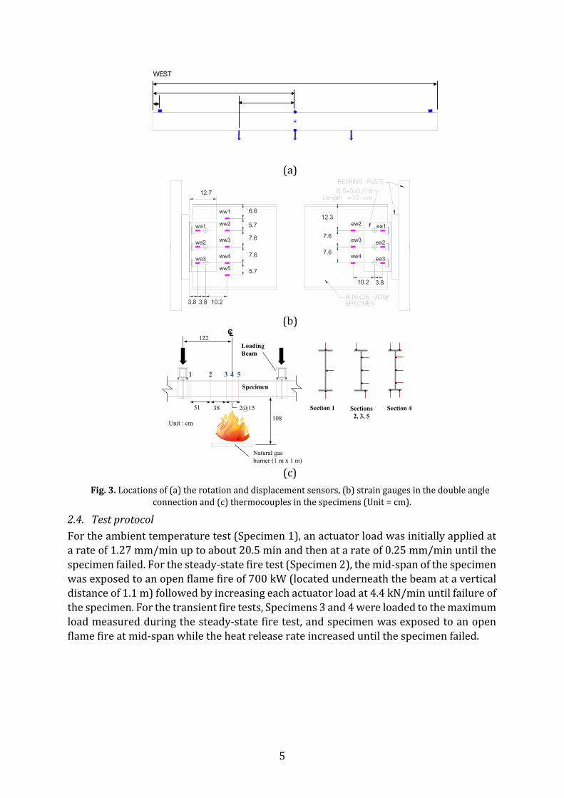
between the support and the specimen to measure the vertical reaction forces. At the mid-span of the fire test specimens, vertical and lateral displacements were measured using string potentiometers with special temperature-compensated probes [18], while conventional string potentiometers were used for the remaining displacement measurements (Fig. 3a). For Specimen 4 with double-angle connections, strain gauges were attached to the legs of the double-angles and the web of the beam (Fig. 3b). Glass-sheathed, K-type, 24-gauge thermocouples were installed at 5 different sections along the length of the beams to measure the temperatures in the fire affected zone of the fire test specimens (Fig. 3c). In addition to the sensors shown in Fig. 3, the heat release rate (HRR) of the natural gas burners as well as force and displacement at each actuator were also measured. For each fire test, two HRRs were measured, one was determined using the measured mass flow and the composition of the natural gas of the burner (burner HRR), and the other was measured by the calorimeter (exhaust hood) based on the amount of oxygen consumed (calorimeter HRR). The differences between the two measured HRRs were negligible and the burner HRRs were presented in this paper. The uncertainty of measurements is reported in Choe et al [18]. The estimated total expanded uncertainty, with a coverage factor of 2, of the force, displacement, and strain measurements were approximately ± 10 %, ± 15 %, and ± 5 %, respectively. The estimated total expanded uncertainty of the steel temperatures and the heat release rates measured using the burners were ± 12 % and ± 7 %, respectively.
(a)
(b)
Side bearings
Support column
Seat support
Top flange of W16x26 specimen
bottom bearing
LoadCell
Seat support
Bottom flange of W16x26 specimen
(c)
Support Column
W16x26 Specimen
L5x5x5/16angle
Safety support
Stiffeners
W16x26Specimen
L5x5x5/16Double angle (229 mm long)
A325 Bolts(19.1 mm dia.)
76.2 mm
W12x106 SupportColumn
(d)
A325 Bolts(25.4 mm dia.)
123.8 mm
76.2 mm76.2 mm
14.3 mm
Sacrificial plate
Bearing plate
5
(a)
(b)
(c)
Fig. 3. Locations of (a) the rotation and displacement sensors, (b) strain gauges in the double angle connection and (c) thermocouples in the specimens (Unit = cm).
2.4. Test protocol For the ambient temperature test (Specimen 1), an actuator load was initially applied at a rate of 1.27 mm/min up to about 20.5 min and then at a rate of 0.25 mm/min until the specimen failed. For the steady-state fire test (Specimen 2), the mid-span of the specimen was exposed to an open flame fire of 700 kW (located underneath the beam at a vertical distance of 1.1 m) followed by increasing each actuator load at 4.4 kN/min until failure of the specimen. For the transient fire tests, Specimens 3 and 4 were loaded to the maximum load measured during the steady-state fire test, and specimen was exposed to an open flame fire at mid-span while the heat release rate increased until the specimen failed.
WEST
10.2
ew2 ea1
ew37.6ea2
ew47.6ea3
12.7
3.8
5.7
3.8
5.7
12.3
10.2
7.6
7.6
3.8
6.6
ww5
ww4
ww3
ww2
ww1
wa3
wa2
wa1
CL
1 2 3 4 5
Specimen
Natural gas burner (1 m x 1 m)
Unit : cm
122
2@153851
Loading Beam
Section 1 Sections2, 3, 5
Section 4108
6
3. Experimental results
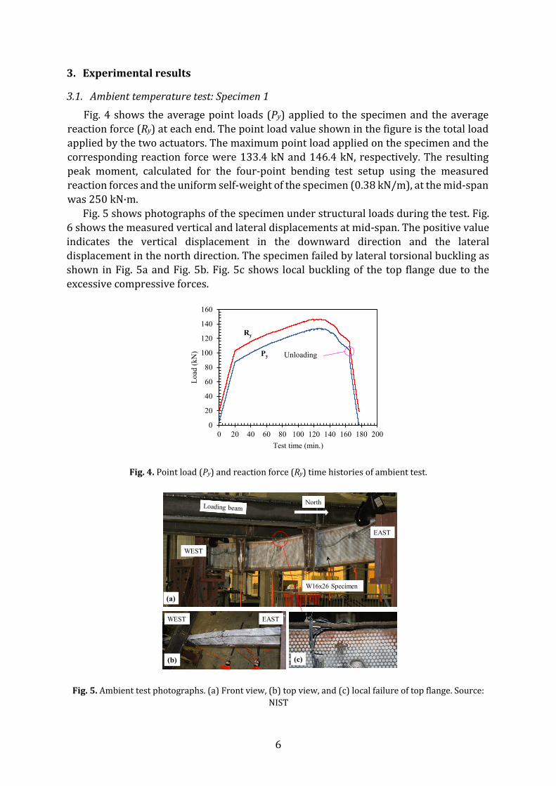
3.1. Ambient temperature test: Specimen 1 Fig. 4 shows the average point loads (Py) applied to the specimen and the average
reaction force (Ry) at each end. The point load value shown in the figure is the total load applied by the two actuators. The maximum point load applied on the specimen and the corresponding reaction force were 133.4 kN and 146.4 kN, respectively. The resulting peak moment, calculated for the four-point bending test setup using the measured reaction forces and the uniform self-weight of the specimen (0.38 kN/m), at the mid-span was 250 kN·m.
Fig. 5 shows photographs of the specimen under structural loads during the test. Fig. 6 shows the measured vertical and lateral displacements at mid-span. The positive value indicates the vertical displacement in the downward direction and the lateral displacement in the north direction. The specimen failed by lateral torsional buckling as shown in Fig. 5a and Fig. 5b. Fig. 5c shows local buckling of the top flange due to the excessive compressive forces.
Fig. 4. Point load (Py) and reaction force (Ry) time histories of ambient test.
Fig. 5. Ambient test photographs. (a) Front view, (b) top view, and (c) local failure of top flange. Source: NIST
0
20
40
60
80
100
120
140
160
0 20 40 60 80 100 120 140 160 180 200
Load
(kN
)
Test time (min.)
Unloading
Ry
Py
(a)
WEST
EAST
WEST EAST
(c)(b)
W16x26 Specimen
North
7
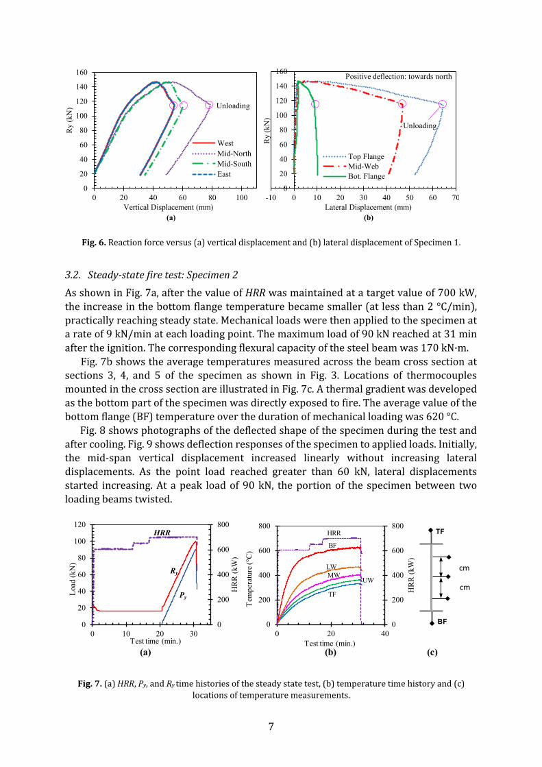
Fig. 6. Reaction force versus (a) vertical displacement and (b) lateral displacement of Specimen 1.
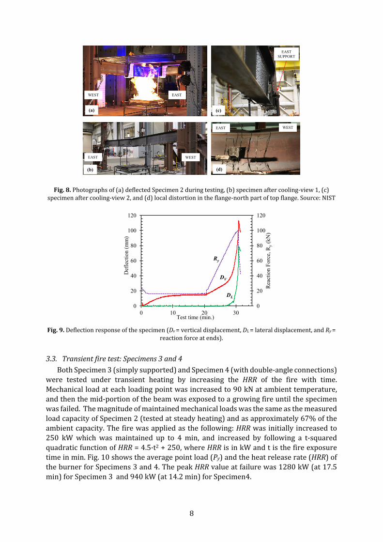
3.2. Steady-state fire test: Specimen 2 As shown in Fig. 7a, after the value of HRR was maintained at a target value of 700 kW, the increase in the bottom flange temperature became smaller (at less than 2 °C/min), practically reaching steady state. Mechanical loads were then applied to the specimen at a rate of 9 kN/min at each loading point. The maximum load of 90 kN reached at 31 min after the ignition. The corresponding flexural capacity of the steel beam was 170 kN·m.
Fig. 7b shows the average temperatures measured across the beam cross section at sections 3, 4, and 5 of the specimen as shown in Fig. 3. Locations of thermocouples mounted in the cross section are illustrated in Fig. 7c. A thermal gradient was developed as the bottom part of the specimen was directly exposed to fire. The average value of the bottom flange (BF) temperature over the duration of mechanical loading was 620 °C. Fig. 8 shows photographs of the deflected shape of the specimen during the test and after cooling. Fig. 9 shows deflection responses of the specimen to applied loads. Initially, the mid-span vertical displacement increased linearly without increasing lateral displacements. As the point load reached greater than 60 kN, lateral displacements started increasing. At a peak load of 90 kN, the portion of the specimen between two loading beams twisted.
Fig. 7. (a) HRR, Py, and Ry time histories of the steady state test, (b) temperature time history and (c) locations of temperature measurements.
0
20
40
60
80
100
120
140
160
0 20 40 60 80 100
Ry
(kN
)
Vertical Displacement (mm)
WestMid-NorthMid-SouthEast
Unloading
0
20
40
60
80
100
120
140
160
-10 0 10 20 30 40 50 60 70
Ry
(kN
)
Lateral Displacement (mm)
Top FlangeMid-WebBot. Flange
Positive deflection: towards north
Unloading
(a) (b)
0
200
400
600
800
0
20
40
60
80
100
120
0 10 20 30
HR
R (k
W)
Load
(kN
)
Test time (min.)
Ry
Py
HRR
0
200
400
600
800
0
200
400
600
800
0 20 40
HR
R (k
W)
Tem
pera
ture
(°C
)
Test time (min.)
BF
HRR
UWMWLW
TF
cm
cm
TF
BF
(a) (b) (c)
8
Fig. 8. Photographs of (a) deflected Specimen 2 during testing, (b) specimen after cooling-view 1, (c) specimen after cooling-view 2, and (d) local distortion in the flange-north part of top flange. Source: NIST
Fig. 9. Deflection response of the specimen (Dv = vertical displacement, DL = lateral displacement, and Ry =
reaction force at ends).
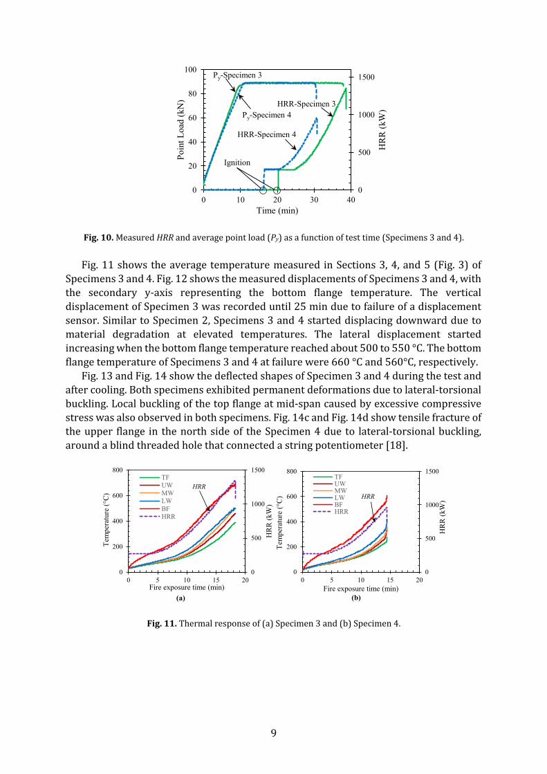
3.3. Transient fire test: Specimens 3 and 4 Both Specimen 3 (simply supported) and Specimen 4 (with double-angle connections)
were tested under transient heating by increasing the HRR of the fire with time. Mechanical load at each loading point was increased to 90 kN at ambient temperature, and then the mid-portion of the beam was exposed to a growing fire until the specimen was failed. The magnitude of maintained mechanical loads was the same as the measured load capacity of Specimen 2 (tested at steady heating) and as approximately 67% of the ambient capacity. The fire was applied as the following: HRR was initially increased to 250 kW which was maintained up to 4 min, and increased by following a t-squared quadratic function of HRR = 4.5·t2 + 250, where HRR is in kW and t is the fire exposure time in min. Fig. 10 shows the average point load (Py) and the heat release rate (HRR) of the burner for Specimens 3 and 4. The peak HRR value at failure was 1280 kW (at 17.5 min) for Specimen 3 and 940 kW (at 14.2 min) for Specimen4.
(a)
WEST
(c)
(d)(b)
EAST
WEST
EASTSUPPORT
WESTEAST
EAST
0
20
40
60
80
100
120
0
20
40
60
80
100
120
0 10 20 30
Rea
ctio
n Fo
rce,
Ry
(kN
)
Def
lect
ion
(mm
)
Test time (min.)
Ry
DV
DL
9
Fig. 10. Measured HRR and average point load (Py) as a function of test time (Specimens 3 and 4).
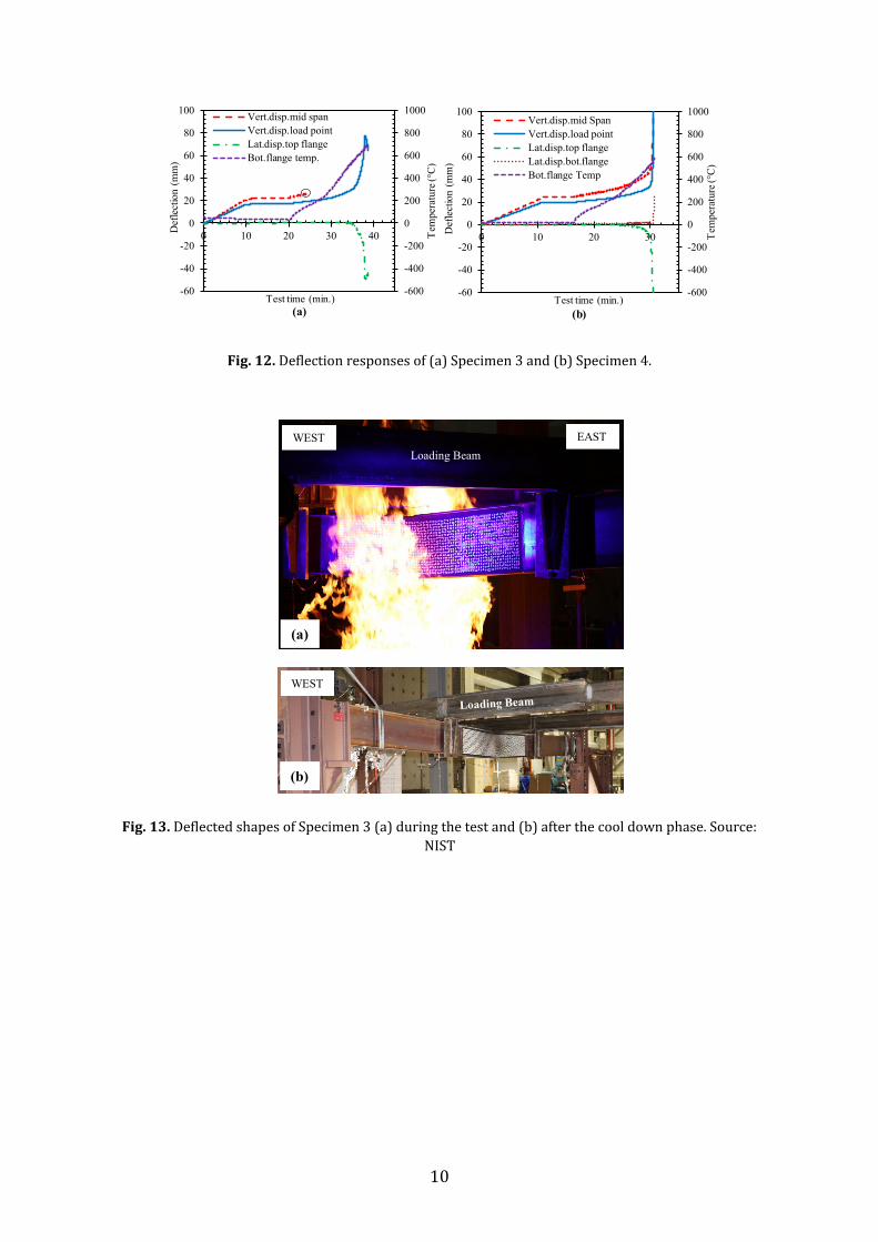
Fig. 11 shows the average temperature measured in Sections 3, 4, and 5 (Fig. 3) of Specimens 3 and 4. Fig. 12 shows the measured displacements of Specimens 3 and 4, with the secondary y-axis representing the bottom flange temperature. The vertical displacement of Specimen 3 was recorded until 25 min due to failure of a displacement sensor. Similar to Specimen 2, Specimens 3 and 4 started displacing downward due to material degradation at elevated temperatures. The lateral displacement started increasing when the bottom flange temperature reached about 500 to 550 °C. The bottom flange temperature of Specimens 3 and 4 at failure were 660 °C and 560°C, respectively.
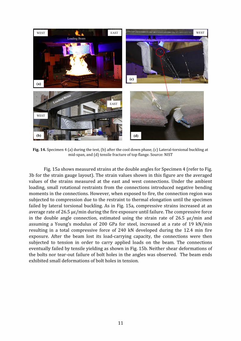
Fig. 13 and Fig. 14 show the deflected shapes of Specimen 3 and 4 during the test and after cooling. Both specimens exhibited permanent deformations due to lateral-torsional buckling. Local buckling of the top flange at mid-span caused by excessive compressive stress was also observed in both specimens. Fig. 14c and Fig. 14d show tensile fracture of the upper flange in the north side of the Specimen 4 due to lateral-torsional buckling, around a blind threaded hole that connected a string potentiometer [18].
Fig. 11. Thermal response of (a) Specimen 3 and (b) Specimen 4.
0
500
1000
1500
0
20
40
60
80
100
0 10 20 30 40
HR
R (k
W)
Poin
t Loa
d (k
N)
Time (min)
Py-Specimen 3
Py-Specimen 4HRR-Specimen 3
HRR-Specimen 4
Ignition
(a) (b)
0
500
1000
1500
0
200
400
600
800
0 5 10 15 20
HR
R (k
W)
Tem
pera
ture
(°C
)
Fire exposure time (min)
TFUWMWLWBFHRR
HRR
0
500
1000
1500
0
200
400
600
800
0 5 10 15 20
HR
R (k
W)
Tem
pera
ture
(°C
)
Fire exposure time (min)
TFUWMWLWBFHRR
HRR
10
Fig. 12. Deflection responses of (a) Specimen 3 and (b) Specimen 4.
Fig. 13. Deflected shapes of Specimen 3 (a) during the test and (b) after the cool down phase. Source: NIST
-600
-400
-200
0
200
400
600
800
1000
-60
-40
-20
0
20
40
60
80
100
0 10 20 30 40 Tem
pera
ture
(°C
)
Def
lect
ion
(mm
)
Test time (min.)
Vert.disp.mid spanVert.disp.load pointLat.disp.top flangeBot.flange temp.
(a)-600
-400
-200
0
200
400
600
800
1000
-60
-40
-20
0
20
40
60
80
100
0 10 20 30 Tem
pera
ture
(°C
)
Def
lect
ion
(mm
)
Test time (min.)
Vert.disp.mid SpanVert.disp.load pointLat.disp.top flangeLat.disp.bot.flangeBot.flange Temp
(b)
(a)
WEST EASTLoading Beam
WEST
(b)
11
Fig. 14. Specimen 4 (a) during the test, (b) after the cool down phase, (c) Lateral-torsional buckling at mid-span, and (d) tensile fracture of top flange. Source: NIST
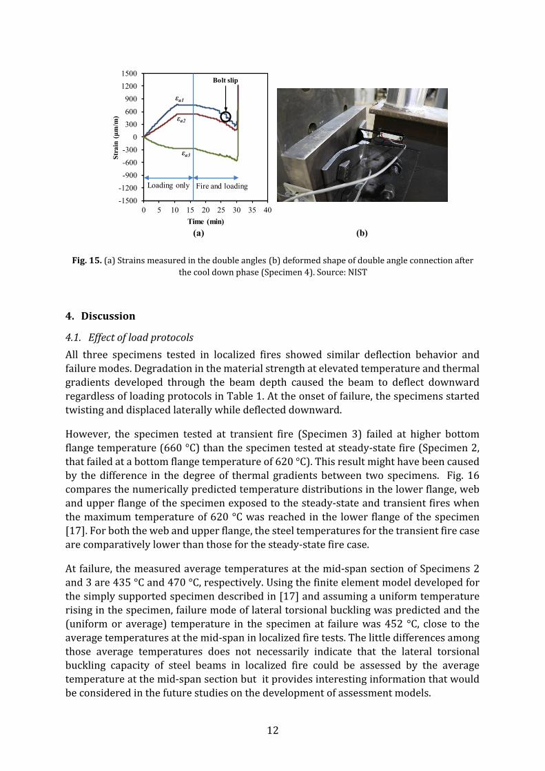
Fig. 15a shows measured strains at the double angles for Specimen 4 (refer to Fig. 3b for the strain gauge layout). The strain values shown in this figure are the averaged values of the strains measured at the east and west connections. Under the ambient loading, small rotational restraints from the connections introduced negative bending moments in the connections. However, when exposed to fire, the connection region was subjected to compression due to the restraint to thermal elongation until the specimen failed by lateral torsional buckling. As in Fig. 15a, compressive strains increased at an average rate of 26.5 µɛ/min during the fire exposure until failure. The compressive force in the double angle connection, estimated using the strain rate of 26.5 µɛ/min and assuming a Young’s modulus of 200 GPa for steel, increased at a rate of 19 kN/min resulting in a total compressive force of 240 kN developed during the 12.4 min fire exposure. After the beam lost its load-carrying capacity, the connections were then subjected to tension in order to carry applied loads on the beam. The connections eventually failed by tensile yielding as shown in Fig. 15b. Neither shear deformations of the bolts nor tear-out failure of bolt holes in the angles was observed. The beam ends exhibited small deformations of bolt holes in tension.
(a)
EAST
Loading Beam
EAST
(b) (d)
(c)
WEST WEST
WEST
12
Fig. 15. (a) Strains measured in the double angles (b) deformed shape of double angle connection after the cool down phase (Specimen 4). Source: NIST
4. Discussion
4.1. Effect of load protocols All three specimens tested in localized fires showed similar deflection behavior and failure modes. Degradation in the material strength at elevated temperature and thermal gradients developed through the beam depth caused the beam to deflect downward regardless of loading protocols in Table 1. At the onset of failure, the specimens started twisting and displaced laterally while deflected downward.
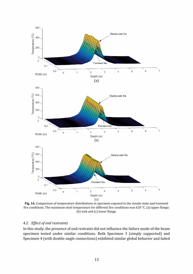
However, the specimen tested at transient fire (Specimen 3) failed at higher bottom flange temperature (660 °C) than the specimen tested at steady-state fire (Specimen 2, that failed at a bottom flange temperature of 620 °C). This result might have been caused by the difference in the degree of thermal gradients between two specimens. Fig. 16 compares the numerically predicted temperature distributions in the lower flange, web and upper flange of the specimen exposed to the steady-state and transient fires when the maximum temperature of 620 °C was reached in the lower flange of the specimen [17]. For both the web and upper flange, the steel temperatures for the transient fire case are comparatively lower than those for the steady-state fire case.
At failure, the measured average temperatures at the mid-span section of Specimens 2 and 3 are 435 °C and 470 °C, respectively. Using the finite element model developed for the simply supported specimen described in [17] and assuming a uniform temperature rising in the specimen, failure mode of lateral torsional buckling was predicted and the (uniform or average) temperature in the specimen at failure was 452 °C, close to the average temperatures at the mid-span in localized fire tests. The little differences among those average temperatures does not necessarily indicate that the lateral torsional buckling capacity of steel beams in localized fire could be assessed by the average temperature at the mid-span section but it provides interesting information that would be considered in the future studies on the development of assessment models.
-1500-1200-900-600-300
0300600900
12001500
0 5 10 15 20 25 30 35 40
Stra
in (μm
/m)
Time (min)
Bolt slip
εa1
εa2
εa3
Loading only Fire and loading
(a) (b)
13
(a)
(b)
(c)
Fig. 16. Comparison of temperature distributions in specimen exposed to the steady-state and transient fire conditions. The maximum steel temperature for different fire conditions was 620 °C. (a) upper flange;
(b) web and (c) lower flange.
4.2. Effect of end restraints In this study, the presence of end restraint did not influence the failure mode of the beam specimen tested under similar conditions. Both Specimen 3 (simply supported) and Specimen 4 (with double-angle connections) exhibited similar global behavior and failed
14
by lateral torsional buckling. However, the bottom flange temperature with the double angle connections failed sooner and at about 150 °C lower bottom flange temperature.
5. CONCLUSIONS
The traditional testing methods for evaluating the fire performance of structures are based on the standard fire environment which assumes a uniform heating condition. As a result, structural fire tests are usually conducted in furnaces (note that by proper design, the standard fire environment can be approximated in a real compartment outside a furnace [23]). This paper presents a localized fire testing method which might be used to validate predictive models of structures in large enclosure or open spaces. Three 6.2 m long W16 × 26 bare steel beams were exposed to localized fires using a natural gas burner. Although further study is needed, the experimental investigation presented in this paper indicates the following:
• Localized fire exposure would not change the lateral torsional failure mode from ambient conditions regardless of heating conditions and end support conditions.
• Failure temperature of the specimen exposed to localized fires could be affected by the fire and loading protocols (heating to failure versus loading to failure). The specimen could fail at lower bottom flange temperatures under steady heating than transient heating.
• Failure temperature of the specimen subjected to a localized fire could be lowered by the presence of end restraints.
Acknowledgements
The support of numerous NIST colleagues on this work is acknowledged and greatly appreciated: John Gross, Brian Story, Anthony Chakalis, Laurean DeLauter, Philip Deardorff, Artur Chernovsky, Doris Rinehart, Matthew Bundy, Matthew Hoehler, and Mina Seif. References
[1] C. Zhang, G.Q. Li. Fire dynamic simulation on thermal actions in localized fires in large enclosure, Advanced Steel Construction, 2012;8:124-36.
[2] Y. Hasemi, Y. Yokobayashi, T. Wakamatsu, A. Ptchelintsev. Modeling of heating mechanism and thermal response of structural components exposed to localized fires: A new application of diffusion flame modeling to fire safety engineering, NIST internal report 6030, National Institute of Standards and Technology (NIST), Gaithersburg, Maryland, 2010.
[3] J. Cadorin, D. Pintea, J. Dotreppe, J. Franssen. A tool to design steel elements submitted to compartment fires ozone v2. part 2: Methodology and application, Fire Safety Journal 2003;38:429–451.
[4] BSI. Eurocode 1: Actions on structures - Part 1-2: General rules - Actions on structures exposed to fire, British Standard, 2002.
[5] B. Lattimer. Heat fluxes from fires to surfaces, SFPE handbook of Fire Protection Engineering, 3rd edition, section 2-4, Society of Fire Protection Engineers, Maryland, 2002.
[6] B. Zhao, J. Kruppa. Structural behaviour of an open car park under real fire scenarios, Fire and Materials, 2004;28:269–280.
15
[7] J. Sandstrom, J. Sjostrom, U. Wickstrom, M. Veljkovic, N. Iqbal, J. Sundelin. Steel truss exposed to localized fires, Technical report, Lulea University of Technology, 2015.
[8] G. Ferraz, A. Santiago, J. Rodrigues, P. Barata. Thermal analysis of hollow steel columns exposed to localized fires, Fire Technology, 2016;52:663–681.
[9] N. Tondini, J. Franssen. Analysis of experimental hydrocarbon localised fires with and without engulfed steel members, Fire Safety Journal, 2017;92:9–22.
[10] V. Babrauskas, R. Peacock. Heat release rate: The single most important variable in fire hazard, Fire Safety Journal, 1992;18:255–272.
[11] C. Zhang, J. Gross, T. McAllister, G. Li. Behavior of unrestrained and restrained bare steel columns subjected to localized fire, Journal of Structural Engineering-ASCE, 2015;141(10): 04014239
[12] C. Zhang, G. Li, A. Usmani. Simulating the behavior of restrained steel beams to flame impinged localized fires, Journal of Constructional Steel Research, 2013;83:156–65.
[13] C. Zhang, J. Gross, T. McAllister. Lateral torsional buckling of steel w-beams to localized fires, Journal of Constructional Steel Research, 2013;88:330–308.
[14] A. Agarwal, L. Choe, A. Varma, Fire design of steel columns: effects of thermal gradients, Journal of Constructional Steel Research, 2014;93:107–118.
[15] M. Bundy, A. Hamins, J. Gross, W. Grosshandler, L. Choe. Structural fire experimental capabilities at the nist national fire research laboratory, Fire Technology, 2016;52:959-966.
[16] C. Zhang, L. Choe, J. Gross, S. Ramesh, M. Bundy. Engineering approach for designing a thermal test of real-scale steel beam exposed to localized fire, Fire Technology, 2017;53:1535-1554.
[17] C. Zhang, H. Yu, L. Choe, J. Gross, G. Li. Simulating the fire-thermal-structural behavior in a localized fire test on a bare steel beam, Engineering Structures, 2018;163:61-70.
[18] Choe, L., Ramesh, S., Hoehler, M., Seif, M., Bundy, M., Zhang, C., and Gross, J. (2017). “National Fire Research Laboratory Commissioning Project: Testing Steel Beams under Localized Fire Exposure”, NIST TN 1977, DOI: https://doi.org/10.6028/NIST.TN.1977
[19] AISC, Steel Construction Manual (AISC 360-16), 15th edition, American Institute of Steel Construction (AISC), 2016.
[20] ASTM International, Standard Specification for Structural Shapes, Standard A992, ASTM International, 2015.
[21] ASTM International, Standard Specification for High Strength Structural Bolts, Steel and Alloy Steel, Heat Treated, 120 ksi (830 MPa) and 150 ksi (1040 MPa) Minimum Tensile Strength, Inch and Metric Dimensions, Standard F3125/F3125M15a, ASTM International, 2015.
[22] ASTM International, Standard Specification for Carbon Structural Steel, Standard A36/A36M-14, ASTM International, 2014.
[23] C. Zhang, W. Grosshandler, A. Sauca, L. Choe. Design of an ASTM E119 Fire Environment in a Large Compartment, Fire Technology,2019, DOI: https://doi.org/10.1007/s10694-019-00924-7