Experimental Investigation of SAHs Solar Dryers with...
8
International Journal of Energy and Power Engineering 2015; 4(5): 240-247 Published online September 6, 2015 (http://www.sciencepublishinggroup.com/j/ijepe) doi: 10.11648/j.ijepe.20150405.11 ISSN: 2326-957X (Print); ISSN: 2326-960X (Online) Experimental Investigation of SAHs Solar Dryers with Zigzag Aluminum Cans Mustafa Adil, Osama Ibrahim, Zainalabdeen Hussein, Kaleid Waleed Renewable Energy Research Center, University of Anbar, Ramadi, Iraq Email address: [email protected] (M. Adil), [email protected] (O. Ibrahim), [email protected] (Z. Hussein), [email protected] (K. Waleed) To cite this article: Mustafa Adil, Osama Ibrahim, Zainalabdeen Hussein, Kaleid Waleed. Experimental Investigation of SAHs Solar Dryers with Zigzag Aluminum Cans. International Journal of Energy and Power Engineering. Vol. 4, No. 5, 2015, pp. 240-247. doi: 10.11648/j.ijepe.20150405.11 Abstract: This experimental study investigates the thermal performance of two different solar-air collector designs for Ramadi climate conditions. Two types of absorber plate are fabricated and tested. Type (I) uses an absorber plate without cans, whereas Type (II) uses one with cans, these cans are arranged in a zigzag pattern. These collectors are a single-duct double-pass type. Air first enters through the inlet and then passes over the absorber plate before returning underneath the absorber and moving toward the outlet duct. Moreover, the plate is covered with 4 mm thick glass. An axial fan is used for air circulation. As a result, the increase in temperature difference is approximately 3 °C to 10.5 °C when using aluminum cans with a zigzag array. The increase in thermal efficiency between Types I and II is approximately 20%. Additionally, at an average mass flow rate of 0.075 kg/s, the difference between the practical and theoretical thermal efficiencies for the two models is approximately 3%. Keywords: SAHs, Solar Dryer, Aluminum Cans, Zigzag, Thermal Performance 1. Introduction Solar radiation is one of the more diverse, abundant and obtainable renewable energy resources. Such energy can be captured and used both directly and indirectly. Moreover, solar power can significantly contribute to reducing carbon emissions from fossil fuels. Solar solutions offer additional opportunities to meet the requirements of planning policies and building regulations [1]. Solar radiation can be directly converted into heat, numerous types of equipment are available to achieve such conversion. A flat plate collector is a device used to achieve this aim. This collector consists of three main parts that govern the design requirements. A glass cover is fixed above the absorber plate, and the system is insulated thermally from the back and sides. Solar air heaters (SAHs) are simple in design and easy to maintain. Corrosion and leakage problems are less severe than those in liquid heater solar systems. Flat plate collectors have been in service for a long time without any significant changes in their design and operational principles [2]. The main drawback of a SAH is that the heat-transfer coefficient between the absorber plate and the air stream is low, which results in low thermal efficiency. If the suggested modifications are implemented, this could improve in the heat-transfer coefficient between the absorber plate and air [3]. Numerous numerical and experimental investigations have been conducted to enhance the thermal performance of flat plate solar collectors. Ion V. ION and Jorge G. MARTINS [4] showed that the performance of air-solar collectors can be enhanced in different ways. These methods include using good thermal insulation, a cover with high transmittance, low absorbance and thermal conductivity of the material as well as using a low-cost absorber with high absorption and thermal conductivity. Also constructing a flow duct with low-pressure losses and using a fan with an appropriate power-flow rate characteristic. Hikmet Esen [5] experimentally analyzed a novel flat plate SAH with several obstacles and another without obstacles. Four types of double-flow solar air collectors under a wide range of operating conditions were studied to evaluate energetic and exergetic efficiencies. Esen showed that the flat plate collector with obstacles had the highest efficiency. Filiz Ozgen et al. [6] experimentally investigated the effect of inserting an absorbing plate made of aluminum cans into the double-pass channel in a flat-plate SAH on thermal performance. Three different absorber plates were designed and tested for the experimental study. They
Transcript of Experimental Investigation of SAHs Solar Dryers with...

International Journal of Energy and Power Engineering 2015; 4(5): 240-247
Published online September 6, 2015 (http://www.sciencepublishinggroup.com/j/ijepe)
doi: 10.11648/j.ijepe.20150405.11
ISSN: 2326-957X (Print); ISSN: 2326-960X (Online)
Experimental Investigation of SAHs Solar Dryers with Zigzag Aluminum Cans
Mustafa Adil, Osama Ibrahim, Zainalabdeen Hussein, Kaleid Waleed
Renewable Energy Research Center, University of Anbar, Ramadi, Iraq
Email address: [email protected] (M. Adil), [email protected] (O. Ibrahim), [email protected] (Z. Hussein),
[email protected] (K. Waleed)
To cite this article: Mustafa Adil, Osama Ibrahim, Zainalabdeen Hussein, Kaleid Waleed. Experimental Investigation of SAHs Solar Dryers with Zigzag
Aluminum Cans. International Journal of Energy and Power Engineering. Vol. 4, No. 5, 2015, pp. 240-247. doi: 10.11648/j.ijepe.20150405.11
Abstract: This experimental study investigates the thermal performance of two different solar-air collector designs for Ramadi
climate conditions. Two types of absorber plate are fabricated and tested. Type (I) uses an absorber plate without cans, whereas
Type (II) uses one with cans, these cans are arranged in a zigzag pattern. These collectors are a single-duct double-pass type. Air
first enters through the inlet and then passes over the absorber plate before returning underneath the absorber and moving toward
the outlet duct. Moreover, the plate is covered with 4 mm thick glass. An axial fan is used for air circulation. As a result, the
increase in temperature difference is approximately 3 °C to 10.5 °C when using aluminum cans with a zigzag array. The increase
in thermal efficiency between Types I and II is approximately 20%. Additionally, at an average mass flow rate of 0.075 kg/s, the
difference between the practical and theoretical thermal efficiencies for the two models is approximately 3%.
Keywords: SAHs, Solar Dryer, Aluminum Cans, Zigzag, Thermal Performance
1. Introduction
Solar radiation is one of the more diverse, abundant and
obtainable renewable energy resources. Such energy can be
captured and used both directly and indirectly. Moreover, solar
power can significantly contribute to reducing carbon
emissions from fossil fuels. Solar solutions offer additional
opportunities to meet the requirements of planning policies
and building regulations [1].
Solar radiation can be directly converted into heat,
numerous types of equipment are available to achieve such
conversion. A flat plate collector is a device used to achieve
this aim. This collector consists of three main parts that govern
the design requirements. A glass cover is fixed above the
absorber plate, and the system is insulated thermally from the
back and sides. Solar air heaters (SAHs) are simple in design
and easy to maintain. Corrosion and leakage problems are less
severe than those in liquid heater solar systems. Flat plate
collectors have been in service for a long time without any
significant changes in their design and operational principles
[2].
The main drawback of a SAH is that the heat-transfer
coefficient between the absorber plate and the air stream is low,
which results in low thermal efficiency. If the suggested
modifications are implemented, this could improve in the
heat-transfer coefficient between the absorber plate and air
[3].
Numerous numerical and experimental investigations have
been conducted to enhance the thermal performance of flat
plate solar collectors. Ion V. ION and Jorge G. MARTINS [4]
showed that the performance of air-solar collectors can be
enhanced in different ways. These methods include using
good thermal insulation, a cover with high transmittance, low
absorbance and thermal conductivity of the material as well as
using a low-cost absorber with high absorption and thermal
conductivity. Also constructing a flow duct with low-pressure
losses and using a fan with an appropriate power-flow rate
characteristic. Hikmet Esen [5] experimentally analyzed a
novel flat plate SAH with several obstacles and another
without obstacles. Four types of double-flow solar air
collectors under a wide range of operating conditions were
studied to evaluate energetic and exergetic efficiencies. Esen
showed that the flat plate collector with obstacles had the
highest efficiency. Filiz Ozgen et al. [6] experimentally
investigated the effect of inserting an absorbing plate made of
aluminum cans into the double-pass channel in a flat-plate
SAH on thermal performance. Three different absorber plates
were designed and tested for the experimental study. They

241 Mustafa Adil et al.: Experimental Investigation of SAHs Solar Dryers with Zigzag Aluminum Cans
found that the optimal collector efficiency
zigzag cans at a 0.05 kg/s mass flow rate. K. Sopian et al. [7]
concluded that the addition of porous media to the second
channel of the double-pass solar air collector enhanced
collector performance. As a result, the typical thermal
efficiency of the double-pass solar collector with porou
media reached approximately 60 - 70%. They also found close
agreement between the theoretical simulation and
experimental data. Ali Zomorodian and Maryam Zamanian [8]
experimentally investigated a flat plate solar air collector
under direct solar radiation to enhance the thermal efficiency
with a slatted glass cover and two different absorber plates
with two thicknesses under different air mass flow rates.
found that a maximum thermal efficiency of 0.88
achieved for the thickest, more porous abso
highest air mass flow rate.
In this study, a solar air heater with aluminum cans in a
zigzag arrangement was constructed to determine the thermal
performance of modified SAHs experimentally. The
performance was then compared with that o
plate solar heaters.
The applications of SAHs include the drying or treatment of
agricultural goods, space heating, regeneration of
dehumidifying agents, seasoning of timber and curing
industrial products such as plastics.
2. Experimental Procedure
In this experimental work, the performance of
conventional absorber plate is compared with the newly
proposed absorber plate having aluminum cans.
2.1. Model I: SAH Collector Without Cans
Model I, is a solar air collector using an absorber pla
without aluminum cans, as shown in Fig. 1(a). Model I has
an outdoor flow loop which comprises a conventional
absorber plate a single-duct double-pass solar air collector
.: Experimental Investigation of SAHs Solar Dryers with Zigzag Aluminum Cans
found that the optimal collector efficiency was achieved for
ow rate. K. Sopian et al. [7]
concluded that the addition of porous media to the second
pass solar air collector enhanced
collector performance. As a result, the typical thermal
pass solar collector with porous
70%. They also found close
agreement between the theoretical simulation and
Ali Zomorodian and Maryam Zamanian [8]
experimentally investigated a flat plate solar air collector
on to enhance the thermal efficiency
with a slatted glass cover and two different absorber plates
with two thicknesses under different air mass flow rates. They
found that a maximum thermal efficiency of 0.88 was
for the thickest, more porous absorption plate at the
In this study, a solar air heater with aluminum cans in a
zigzag arrangement was constructed to determine the thermal
performance of modified SAHs experimentally. The
with that of conventional flat
The applications of SAHs include the drying or treatment of
agricultural goods, space heating, regeneration of
dehumidifying agents, seasoning of timber and curing
In this experimental work, the performance of
conventional absorber plate is compared with the newly
proposed absorber plate having aluminum cans.
2.1. Model I: SAH Collector Without Cans
Model I, is a solar air collector using an absorber plate
without aluminum cans, as shown in Fig. 1(a). Model I has
an outdoor flow loop which comprises a conventional
pass solar air collector
with entrance and exit sections, an air blower, a vane
anemometer, a pyrometer, and a thermocouple for
temperature measurement. A schematic illustration of the
SAH collector of Model I is shown in and Fig. 2(a).
a) Model I
Figure 1. Photographs of SAH collector Models I and II.
2.2. Model II: SAH Collector with
Model II, is a solar air collector using an absorber plate
with aluminum cans in a zigzag arrangement, as shown in
Fig. 1(b). Model II has an outdoor flow loop comprising
aluminum cans as obstacles, a single
air collector with entrance and exit sections, an air blower, a
vane-type anemometer, a pyranometer, and a thermocouple
for temperature measurement. A schematic illustration of the
SAH collector of Model II is shown
a) Model I (Flat plate collector without Al cans)
.: Experimental Investigation of SAHs Solar Dryers with Zigzag Aluminum Cans
with entrance and exit sections, an air blower, a vane-type
r, and a thermocouple for
temperature measurement. A schematic illustration of the
SAH collector of Model I is shown in and Fig. 2(a).
b) Model II
of SAH collector Models I and II.
2.2. Model II: SAH Collector with Cans
Model II, is a solar air collector using an absorber plate
with aluminum cans in a zigzag arrangement, as shown in
Model II has an outdoor flow loop comprising
aluminum cans as obstacles, a single-duct double-pass solar
ntrance and exit sections, an air blower, a
type anemometer, a pyranometer, and a thermocouple
A schematic illustration of the
is shown in Fig. 2(b).

International Journal of Energy and Power Engineering 2015; 4(5): 240-247 242
b) Model II (Flat plate collector with Al cans)
Figure 2. Schematic illustration of the SAH collectors: a) Model I and b) Model II.
2.3. Materials
The collector plates were 1 mm thick and made of
aluminum sheet with the size 2.20 m × 0.84 m having a 32°
angle of inclination. The absorber plate was then painted
with solar thermal black paint (selective coating). The
copper sheet was 0.1 mm thick and was installed on the
bottom duct. The sheet had a specific heat capacity of 0.385
J/g·°C, thermal conductivity of 386 W/m·K, the absorbance
of 0.94, and permeability of 0.03. The aluminum cans served
as obstacles and were placed on the top and bottom of
absorber plate. A single glass cover 4 mm thick was used as
glazing for the two collectors. The frame of the collectors
was constructed using wood. Therefore, the thermal losses
from the back of collectors attributed to conduction,
convection, and radiation are assumed negligible. All the
specifications of these collectors are shown in Table 1.
Table 1. Specifications of SAH collector.
Collector tilt angle (degree) 32 [9]
Collector length (cm) 240
Collector width (cm) 88
Overall height (cm) 15
Upper duct height (cm) 8
Lower duct height (cm) 7
Inlet Area (m2) 0.0869
Outlet Area (m2) 0.049
Exposed Area (m2) 1.8 * 0.81
Plate type Flat plate
Cover material Commercial clear glass Ʈ=0.86 [10]
Number of covers 1
2.4. The Measurement
An auto-controller was used to vary the speed of the air
blower. An anemometer was used to measure air velocity.
Calibrated copper–constantan thermocouples were used to
measure the temperature of the inlet and outlet air. The
heated absorber plates were placed in different positions, and
temperatures were measured by using a digital thermometer.
All components were checked, and the instruments were
calibrated. The axial fan was then switched “on” and joints
were checked for leakages. All experiments were conducted
under the climatic conditions of Al-Ramadi City (longitude:
33.25° N; latitude: 43.18° E; facing south) for two selected
clear days on 11 March and 7 April 2014. The average mass
flow rate was set at 0.075 kg/s. The following parameters
were measured: solar intensity, absorber plate temperature,
inlet air temperature, outlet air temperature and air velocity.
3. Thermal Performance Calculation
To calculate the heat gain (qu) and thermal efficiency (ƞth)
of the solar air collector, the following must be calculated:
the average of inlet and outlet temperature Ti and To,
respectively; specific heat capacity of air Cp; density ρ; air
velocity vinlet, and the inclination of the collector [9]. The
thermal gain produced by the SAH can be calculated as in Eq.
(1):
q� = m� × cp T� − T�� (1)
Where, m� ) is a mass air flow rate (kg sec−1
), which can be
calculated as in Eq. (2):
m� = ρ × v����� × A����� (2)
Where Ainlet, is the area of the inlet. The thermal efficiency
of the solar air collectors (ηth) is defined as the ratio between
the energy gain and the solar radiation incident on the
collector plane and can be evaluated as in Eq. (3):
η�� = �� ����� ×� !"#$ %
(3)
where Aexposed is the area covered by the absorber plate (m2),
and Itilt is the intensity of radiation (W·m−2
).
4. Estimation of Solar Radiation
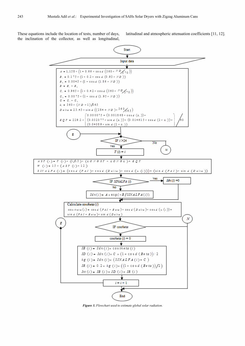
In this work, the flowchart shown in figure 3 is employed to
estimate global solar radiation data by using commonly
available meteorological equations through a mutable
function, as shown below. Many empirical equations and
coefficients have been used to estimate global solar radiation.
243 Mustafa Adil et al.: Experimental Investigation of SAHs Solar Dryers with Zigzag Aluminum Cans
These equations include the location of tests, number of days,
the inclination of the collector, as well as longitudinal,
latitudinal and atmospheric attenuation coefficients [11, 12].
Figure 3. Flowchart used to estimate global solar radiation.

International Journal of Energy and Power Engineering 2015; 4(5): 240-247 244
5. Results and Discussion
The practical results acquired in Al-Ramadi City are
presented and discussed. All experiments for both collectors
were conducted at an average air flow rate of 0.075kg/s.
5.1. Model I: SAH Collector Without Cans
The values of intensity solar radiation for practical and
theoretical conditions which is taken in Al-Ramadi City for
the two selected days (11 March and 7 April 2014) are shown
in Figs. 4 and 5, respectively. These measurements is also
carried out for slope and horizontal plan. The values of
incident solar radiation increased gradually to the peak value
at midday and then decrease steadily from sunrise to sunset.
The practical and theoretical data of the figures 4 & 5 have
been used to evaluate the hourly and daily variation of a
number of parameters such as thermal efficiency. In the other
words, these parameters were evaluated based on the
experimental data and the estimated values of intensity solar
radiation.
Figure 4. Practical and theoretical values of solar radiation on a clear day on
11 March 2014.
Figure 5. Practical and theoretical values of solar radiation on a clear day on
7 April 2014.
Figure 6 shows the temperature distribution for Model I
(without cans) on a clear day on 11 March 2014. For every half
hour during daytime; the normal behavior of inlet, outlet, and
surface temperatures might be observed for two essential
reasons; firstly, the air flow rate fluctuation which could be
caused by a number of reasons for instance, the effect of
variation of wind speed that could change the air inlet velocity.
This variation also affected on wind heat transfer coefficient
[10] as shown below:
hw = 5.7 + 3.8Vw (4)
Figure 6. Temperature variation of the inlet, outlet, and surface for Model I
on a clear day on 11 March 2014.
The increasing of this coefficient will increase the overall
heat transfer losses. In addition, the absence of sun rays for a
short time.
The average surface, inlet, and outlet air temperature
variations on a clear day on 11 March 2014 are shown in Fig.
7. The maximum difference between inlet and outlet air
temperatures was approximately 7°C at mid-daytime.
Besides, the minimum air temperature difference was about
3.2°C at 15:00. This attributed for the causes aforementioned
above.
Figure 7. Average surface, inlet, and outlet air temperature variation on a
clear day on 11 March 2014.
Fig. 8 shows the hourly practical and theoretical thermal
efficiencies for Model I (without cans) on 11 March 2014. The
averages of practical and theoretical thermal efficiencies were
49.47% and 46.5%, respectively.
8 9 10 11 12 13 14 15 16
0
100
200
300
400
500
600
700
800
900
1000
1100
So
lar
Rad
iati
on
(W
/m2
)
Time (hours)
hg-Theor.
hg-real
hg-real slope
hg-Theor.slope
8 9 10 11 12 13 14 15 16 17
400
500
600
700
800
900
1000
1100
So
lar
Rad
iati
on
(W
/m2)
Time (hours)
hg real
hg theroritical
hg real slope
hg theroritical slope
8 9 10 11 12 13 14 15 16
15
20
25
30
35
40
45
50
55
Te
mp
era
ture
(o
C)
Time (hours)
Inlet temp
Outlet temp
T1
T2
T3
T4
8 9 10 11 12 13 14 15 16
16
18
20
22
24
26
28
30
32
34
36
38
40
42
44
46
48
50
Tem
pera
ture
(o
C)
Time (hours)
Inlet temp
Outlet temp
Tav sur

245 Mustafa Adil et al.: Experimental Investigation of SAHs Solar Dryers with Zigzag Aluminum Cans
Figure 8. Practical and theoretical thermal efficiencies for Model I on a clear
day on 11 March 2014.
5.2. Model II: SAH Collector with Cans
Figure 9. Temperature variation of the inlet, outlet, and surface for Model II
on a clear day on 7 April 2014.
Figure 10. Average surface, inlet, and outlet air temperature variation for
Model II on a clear day on 7 April 2014.
Figure 9 shows the temperature distribution for Model II
(with cans) on a clear day on 7 April 2014. For every half
hour during the daytime, the fairy normal behavior of inlet,
outlet, and surface temperatures was observed during the
daytime. The average surface, inlet, and outlet air
temperature variations on a clear day on 7 April 2014 are
shown in figure 10. The maximum difference between inlet
and outlet air temperatures was approximately 10 °C at 13:30.
This value is attributed to presence of aluminum cans that act
as extended surfaces. Also, the air temperature difference
values decreased to less than 2°C at 15:30 as minimum value
owing to the value of intensity solar radiation is quite small
which in turn reducing the heat absorbed from aluminum
plate.
Fig. 11 shows the hourly practical and theoretical thermal
efficiencies for Model II (with cans) on a clear day on 7 April
2014. The averages of practical and theoretical thermal
efficiencies were 68.5% and 65.2%, respectively.
Figure 11. Practical and theoretical thermal efficiencies for Model II on a
clear day on 7 April 2014.
5.3. Comparison Between Model I and Model II
Figs. 12 and 13 show the increase in the temperature
difference between Models I and II for two selected clear days
on 11 March and 7 April 2014, respectively. The increase in
temperature differences is approximately 3.2 °C to 10.5 °C.
This increase as result of the using aluminum cans with a
zigzag array. The aluminum cans serve as fins that increase the
capability of the absorber plate to absorb energy, consequently
increasing the heat transfer coefficients, as well as
contributing to the breakage of the boundary layer and
reducing its growth.
Figure 12. Inlet and outlet temperature difference for Models I and II for the
two selected clear days on 11 March and 7 April 2014.
8 9 10 11 12 13 14 15 16 17
20
25
30
35
40
45
50
55
60
Eff
icie
nc
y
Time (hours)
Practical
Theoritical
9 10 11 12 13 14 15 1628
30
32
34
36
38
40
42
44
46
48
50
52
54
56
Te
mp
era
ture
(oC
)
Time (hours)
Tinlet
Toutlet
T1
T2
T3
T4
Tav. sur.
9 10 11 12 13 14 15 1628
30
32
34
36
38
40
42
44
46
48
50
52
Tem
pe
ratu
re (
oC
)
Time (hours)
Tin
Tout
T Ave. Sur.
9 10 11 12 13 14 15 16
54
56
58
60
62
64
66
68
70
72
74
76
78
80
Eff
icie
nc
y
Time (hours)
Practical
Theoritical
9 10 11 12 13 14 15 16 17
3
4
5
6
7
8
9
10
11
Te
mp
era
ture
(o
C)
Time (hr.)
Temp. difference (Model II) 7/4/2014
Temp. difference (Model I) 11/3/2014

International Journal of Energy and Power Engineering 2015; 4(5): 240-247 246
Figure 13. The average surface temperature for Models I and II for two
selected clear days on 11 March and 7 April 2014.
Fig. 14 and Table 2 show the experimental and theoretical
thermal efficiencies for Models I and Model II for the two
selected days. We observe that the difference in the practical
and theoretical thermal efficiencies between Models I and II is
approximately 20%. In addition, the difference between
practical and theoretical thermal efficiencies for the two
models is approximately 3% at an average mass flow rate of
0.075 kg/s. The enhanced efficiency of the solar air collector
in Model II is attributed to the following reasons: using the
cans as extended surfaces (fins) and placing the can array in a
zigzag pattern increases the heat transfer coefficient by
increasing air turbulent flow and reducing the growth of the
boundary layer.
Figure 14. Variation of hourly practical and theoretical thermal efficiencies
for Models I and II.
Table 2. Practical and theoretical thermal efficiencies of Models I and II for two selected sunny days on 11 March and 7 April 2014.
Time ηTheoretical ηPractical e ηTheoretical ηPractical e
Model I Model II
9:00 53.458 56 1.797465438 68.803 79.217 7.363810019
10:00 42.687 53.43 7.59644815 55.380 66.610 7.940809153
11:00 45.209 50.1 3.458459267 59.375 67.409 5.68089588
12:00 50.042 52.55 1.773423807 63.814 70.006 4.378405189
13:00 52.974 53 0.018384776 66.027 69.818 2.680641807
14:00 52.825 50.33 1.764231419 63.008 62.664 0.243244733
15:00 29.740 29.7 0.028284271 74.763 70.924 2.714582933
16:00 45.321 50.7 3.803527376 70.666 61.650 6.375274739
Ave. 46.5 49.476 2.081899141 65.229 68.537 2.338932455
The degree of agreement between the theoretical and
experimental results have been calculated by using a statistical
analysis [10], as shown below:
e=0∑ 2 34��56�7 (5)
89 = :�; <� :�
∗ 100 (6)
Where Xi and Yi are the theoretical and the experimental
results of SAH collector, respectively, (e) the root mean square
of percentage deviation.
This difference between experimental and theoretical
results could be caused by few reasons. One of them, the use
practical and theoretical intensity solar radiation values. As it
is mentioned before, the percentage error between these solar
radiation values around 3 %. This percentage affected directly
on the calculation of the thermal efficiencies. Another reason,
the values of practical intensity solar radiation vary based on
the weather conditions such as dust, humidity etc., some
values therefore behave convergent at 14:00 and behave
divergent at 9:00.
6. Conclusions
An experimental investigation was conducted by the
Renewable Energy Research Center in Al-Ramadi City to
evaluate the thermal performance of two different models of
single-pass double-duct SAHs (solar dryers) with and without
cans (obstacles) arranged in a zigzag pattern as fins. The
thermal performance of the single-pass double-duct type SAH,
in which air flows over and returns under the absorber plate, is
efficient because the flowing air collects and absorbs most of
the supplied energy. The results show an increase in thermal
efficiency of Model II by approximately 20%. Model II was
more efficient and had a maximum temperature difference that
was approximately 10.5 °C higher than that of Model I.
Moreover, the theoretical values of solar radiation used were
satisfactory, and the error in the results was approximately
3%.
8 9 10 11 12 13 14 15 1630
32
34
36
38
40
42
44
46
48
50
52
Tem
pera
ture
(oC
)
Time (hr.)
Average Surface Temp. (Model I) 11/3/2014
Average Surface Temp. (Model II) 7/4/2014
9 10 11 12 13 14 15 16
30
40
50
60
70
80
Eff
icie
nc
yTime (hours)
Practical-Zigzag
Theoritical-Zigzag
Practical-Flat
Theoritical-Flat

247 Mustafa Adil et al.: Experimental Investigation of SAHs Solar Dryers with Zigzag Aluminum Cans
Acknowledgements
This work is supported by the University of
Anbar-Iraq/Renewable Energy Research Center with Grant
No. RERC-PP34.
References
[1] Rawlings R and Butcher K. Capturing solar energy. Chartered Institution of Building Services Engineers 2009.
[2] Raj Thundil Karuppa R, Pavan P, and Reddy Rajeev D., “Experimental Investigation of a New Solar Flat Plate Collector”, Research Journal of Engineering Sciences, 1(4), pp. 1–8, 2012.
[3] Mohamad AA., “High efficiency solar air heater”, Solar Energy, 60(2), pp. 6–71, 1997.
[4] Ion IV and Martins JG., “Design, developing and testing of a solar air collector”, Research Journal of Engineering Sciences, 1(4), pp. 1–8, 2012.
[5] Esen H., “Experimental energy and exergy analysis of a double-flow solar air heater having different obstacles on absorber plates”, Building and Environment, 43, pp. 1046–1054., 2008.
[6] Ozgen F, Esen M, and Esen H., “Experimental Investigation of Thermal Performance of a Double-flow Solar Air Heater Having Aluminium Cans”, Renewable Energy, 34, pp. 2391–2398, 2009.
[7] Sopian K, Alghoul MA, Alfegi EM, Sulaiman MY, and Musa EA., “Evaluation of thermal efficiency of double-pass solar collector with porous–nonporous media”, Renewable Energy, 34, pp. 640–645, 2009.
[8] Zomorodian A and Zamanian MA., “Designing and Evaluating an Innovative Solar Air Collector with Transpired Absorber and Cover”, International Scholarly Research Network ISRN Renewable Energy; 2012 (Article ID 282538), 5 pages, 2012.
[9] ASHRAE Applications Handbook, American Society of Heating, Solar Energy Use (ASHRAE). Atlanta, GA, 1999, Chapter 32.
[10] Amori KE and Abd-AlRaheem MA., “Field study of various air based photovoltaic/thermal hybrid solar collectors”, Renewable Energy, 63, pp. 402–414, 2014.
[11] Duffie JA and Beckman WA., Solar Engineering of Thermal Processes, John Wiley & Sons, Inc 2006.
[12] Kalogirou S., Solar Energy Engineering: Processes and Systems, Cyprus University of Technology, Elsevier’s Science and Technology, USA 2009.