
Circular - Rectangular - Inclined Plate Clarifiers for Wastewater Treatment Process
International Research Journal of Engineering and Technology (IRJET) e-ISSN: 2395 -0056
Volume: 03 Issue: 06 | June-2016 www.irjet.net p-ISSN: 2395-0072
© 2016, IRJET | Impact Factor value: 4.45 | ISO 9001:2008 Certified Journal | Page 1079
Experimental Investigation of Reduction in SCF of Rectangular plate
with central circular hole by Providing Relief Holes
Anita Wankar1, Prof. Hredey Mishra2, Jagadishsingh Bayas3
1 Student, Mechanical Engg. JCOE Kuran, Maharashtra, India 2Asst. Professor, Mechanical Engg. JCOE Kuran, Maharashtra, India
3Student, Mechanical Engg. SAE Kondhwa (BK), Pune, Maharashtra, India ---------------------------------------------------------------------***---------------------------------------------------------------------Abstract - The rectangular plate with the circular hole at the centre used to join to simple elements in lot many structures. The central hole results in high value of stress concentration factor. By provision of relief holes of optimum shape at optimum distance from the centre of the main hole, the value of SCF reduced by considerable amount. The original value of SCF as well as the altered value of Stress concentration factor observed experimentally. Universal testing machine is used here to apply load on the rectangular plate and maximum strain value sensed by strain gauge foils indicated on the digital strain indicator in microns. Calculations for the value of stress concentration factor have done using standard relations.)
Key Words: Strain, strain gauge, relief holes
1. INTRODUCTION The rectangular plate with central circular hole has been used everywhere as a connecting member. The hole provided on the plate make the plate weak and leads to earlier failure of structure. Because of that hole the flow stresses within the plate will get disturb. The stress value near the hole depends on the shape hole, size of hole and relative location of that hole.
1.1 Problem Definition Experimental approach to reduce stress concentration factor of rectangular plate with central circular hole by providing relief holes on either side of main hole.
1.2. Literature Review Basavaraj. R. Endigeri, Vinayak Mannur in “Fem for Stress Reduction by Optimal Relief Holes in A Uniaxially Loaded Composite Plate” carried out to work to locate relief holes with a optimum values of relief hole location and with optimum radii using numerical method. [1] Shubhrata Nagpal1, Nitin Jain, and Shubhashish Sanyal in “Stress Concentration and its Mitigation Techniques in Flat Plate with Singularities: A Critical Review” discussed various stress mitigation techniques. [2]
Chavan Jyoti G., Dixit Supriya S., Pirjade Firdos I. in “Study of Experimental Stress Analysis” have given brief information about experimental stress analysis methods with the help of polariscope. [3] Mr.V.G.Aradhye & Prof.S.S.Kulkarni in “Use of Strain Gauge Rosette to Investigate Stress concentration in Isotropic and Orthotropic Plate with Circular Hole” calculated stress concentration of rectangular isotropic and orthotropic plate with circular hole are in tensile loading on computerized Universal Testing Machine (UTM) and Strain gauge indicator. [4]
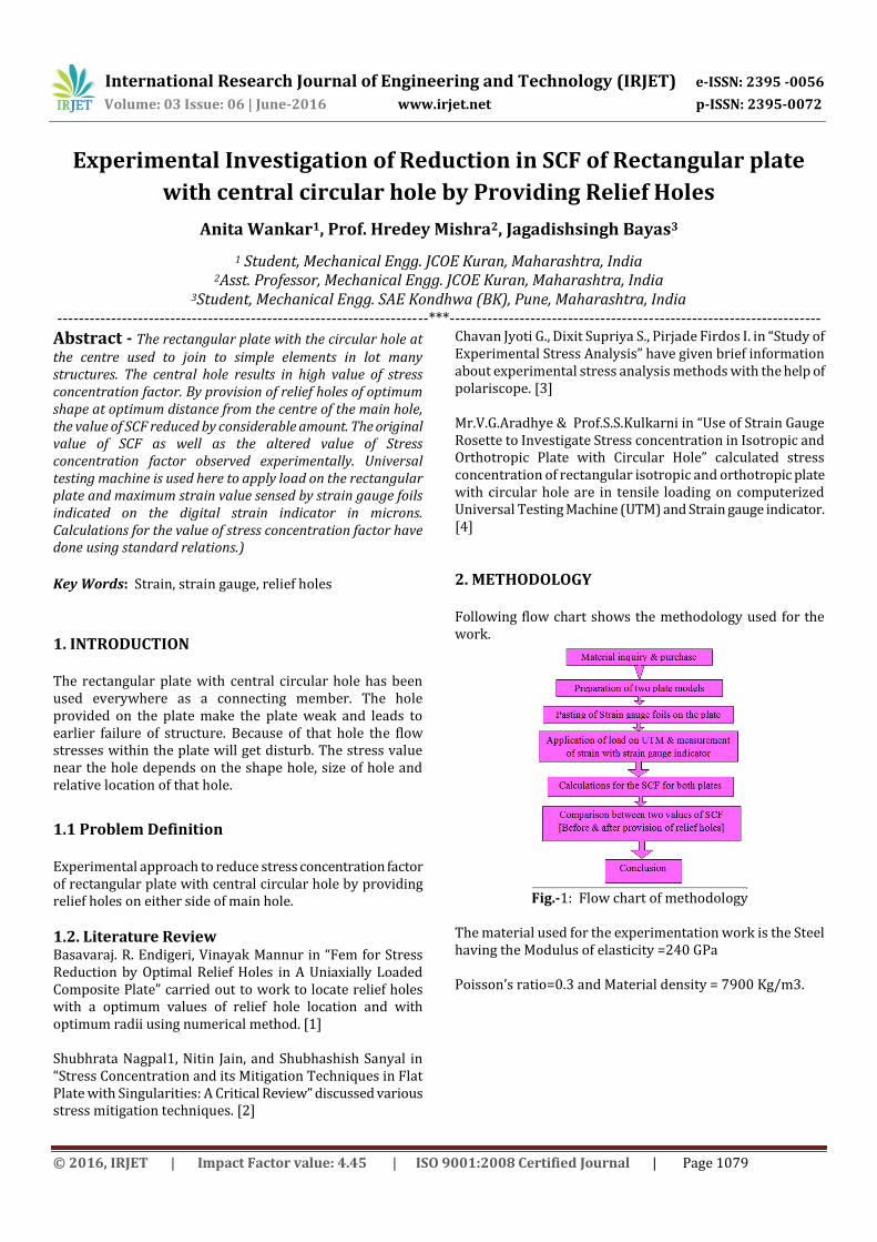
2. METHODOLOGY Following flow chart shows the methodology used for the work.
Fig.-1: Flow chart of methodology
The material used for the experimentation work is the Steel having the Modulus of elasticity =240 GPa Poisson’s ratio=0.3 and Material density = 7900 Kg/m3.
International Research Journal of Engineering and Technology (IRJET) e-ISSN: 2395 -0056
Volume: 03 Issue: 06 | June-2016 www.irjet.net p-ISSN: 2395-0072
© 2016, IRJET | Impact Factor value: 4.45 | ISO 9001:2008 Certified Journal | Page 1080
3. EXPERIMENTATION All the steps used during experimentation are described below.
3.2 Preparation of Plate Material Steel G550 is used for the work. Two rectangular plate models are prepared for testing purpose. Both the plate models are having 200 mm length, 100 mm width and 1 mm thickness. The difference between two is that one plate is having only centre hole of 10 mm dimension. And another one is having centre hole of 10 mm and relief holes of ellipsoidal shape on either side of main hole at 15 mm from the centre of the main hole. The major axis of ellipse (a) is 9.89 mm and minor axis (b) is 2.47 mm. The machining of plate models is done by wire cutting method. Images of the plate models after machining are shown below.
Fig.-2 Plate without Relief holes
Fig.-2 Plate with Relief holes
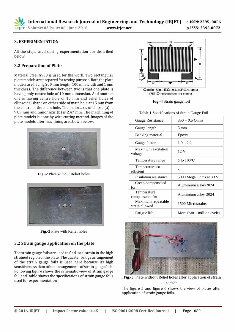
3.2 Strain gauge application on the plate The strain gauge foils are used to find local strain in the high strained region of the plate. The quarter bridge arrangement of the strain gauge foils is used here because its high sensitiveness than other arrangements of strain gauge foils. Following figure shows the schematic view of strain gauge foil and table shows the specifications of strain gauge foils used for experimentation
Fig.-4 Strain gauge foil
Table 1 Specifications of Strain Gauge Foil
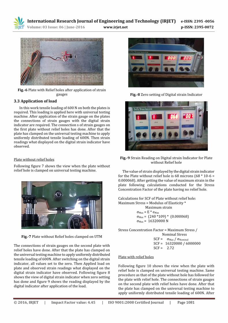
. Fig.-5 Plate without Relief holes after application of strain
gauges
The figure 5 and figure 6 shows the view of plates after application of strain gauge foils.
Gauge Resistance 350 + 0.5 Ohms
Gauge length 5 mm
Backing material Epoxy
Gauge factor 1.9 – 2.2
Maximum excitation
voltage 12 V
Temperature range 5 to 100˚C
Temperature co-
efficient -
Insulation resistance 5000 Mega Ohms at 30 V
Creep compensated
for Aluminium alloy-2024
Temperature
compensated for Aluminium alloy-2024
Maximum repeatable
strain allowed 1500 Microstrains
Fatigue life More than 1 million cycles
International Research Journal of Engineering and Technology (IRJET) e-ISSN: 2395 -0056
Volume: 03 Issue: 06 | June-2016 www.irjet.net p-ISSN: 2395-0072
© 2016, IRJET | Impact Factor value: 4.45 | ISO 9001:2008 Certified Journal | Page 1081
Fig.-6 Plate with Relief holes after application of strain gauges
3.3 Application of load
In this work tensile loading of 600 N on both the plates is required. This loading is applied here with universal testing machine. After application of the strain gauge on the plates the connections of strain gauges with the digital strain indicator are required. The connection s of strain gauges on the first plate without relief holes has done. After that the plate has clamped on the universal testing machine to apply uniformly distributed tensile loading of 600N. Then strain readings what displayed on the digital strain indicator have observed.
Plate without relief holes
Following figure 7 shows the view when the plate without relief hole is clamped on universal testing machine.
Fig.-7 Plate without Relief holes clamped on UTM
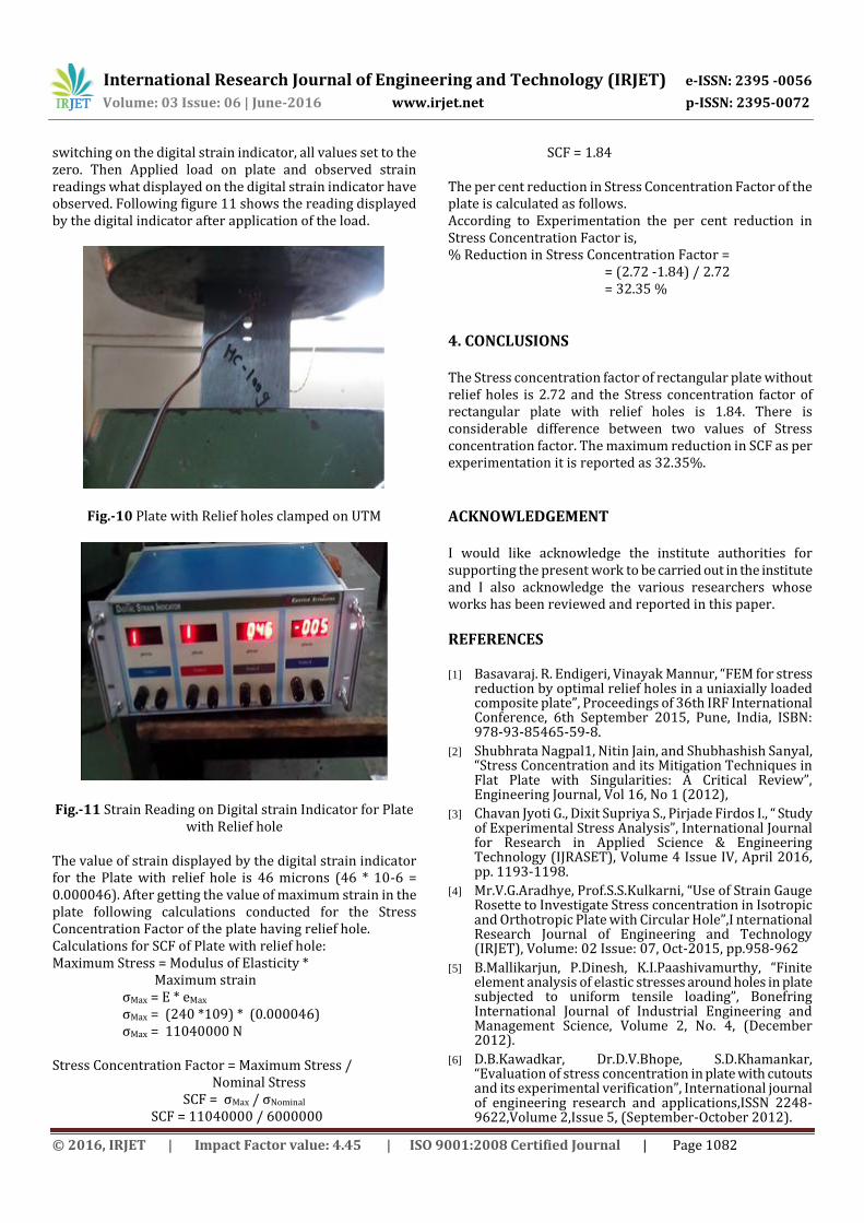
The connections of strain gauges on the second plate with relief holes have done. After that the plate has clamped on the universal testing machine to apply uniformly distributed tensile loading of 600N. After switching on the digital strain indicator, all values set to the zero. Then Applied load on plate and observed strain readings what displayed on the digital strain indicator have observed. Following figure 8 shows the view of digital strain indicator when zero setting has done and figure 9 shows the reading displayed by the digital indicator after application of the load.
Fig.-8 Zero setting of Digital strain Indicator
Fig.-9 Strain Reading on Digital strain Indicator for Plate without Relief hole
The value of strain displayed by the digital strain indicator
for the Plate without relief hole is 68 microns (68 * 10-6 = 0.000068). After getting the value of maximum strain in the plate following calculations conducted for the Stress Concentration Factor of the plate having no relief hole.
Calculations for SCF of Plate without relief hole: Maximum Stress = Modulus of Elasticity * Maximum strain
σMax = E * eMax σMax = (240 *109) * (0.000068) σMax = 16320000 N
Stress Concentration Factor = Maximum Stress / Nominal Stress
SCF = σMax / σNominal SCF = 16320000 / 6000000 SCF = 2.72
Plate with relief holes Following figure 10 shows the view when the plate with relief hole is clamped on universal testing machine. Same procedure as that of the plate without hole has followed for the plate with relief hole. The connections of strain gauges on the second plate with relief holes have done. After that the plate has clamped on the universal testing machine to apply uniformly distributed tensile loading of 600N. After
International Research Journal of Engineering and Technology (IRJET) e-ISSN: 2395 -0056
Volume: 03 Issue: 06 | June-2016 www.irjet.net p-ISSN: 2395-0072
© 2016, IRJET | Impact Factor value: 4.45 | ISO 9001:2008 Certified Journal | Page 1082
switching on the digital strain indicator, all values set to the zero. Then Applied load on plate and observed strain readings what displayed on the digital strain indicator have observed. Following figure 11 shows the reading displayed by the digital indicator after application of the load.
Fig.-10 Plate with Relief holes clamped on UTM
Fig.-11 Strain Reading on Digital strain Indicator for Plate with Relief hole
The value of strain displayed by the digital strain indicator for the Plate with relief hole is 46 microns (46 * 10-6 = 0.000046). After getting the value of maximum strain in the plate following calculations conducted for the Stress Concentration Factor of the plate having relief hole. Calculations for SCF of Plate with relief hole: Maximum Stress = Modulus of Elasticity * Maximum strain
σMax = E * eMax σMax = (240 *109) * (0.000046) σMax = 11040000 N
Stress Concentration Factor = Maximum Stress / Nominal Stress
SCF = σMax / σNominal SCF = 11040000 / 6000000
SCF = 1.84 The per cent reduction in Stress Concentration Factor of the plate is calculated as follows. According to Experimentation the per cent reduction in Stress Concentration Factor is, % Reduction in Stress Concentration Factor = = (2.72 -1.84) / 2.72 = 32.35 %
4. CONCLUSIONS The Stress concentration factor of rectangular plate without relief holes is 2.72 and the Stress concentration factor of rectangular plate with relief holes is 1.84. There is considerable difference between two values of Stress concentration factor. The maximum reduction in SCF as per experimentation it is reported as 32.35%.
ACKNOWLEDGEMENT I would like acknowledge the institute authorities for supporting the present work to be carried out in the institute and I also acknowledge the various researchers whose works has been reviewed and reported in this paper.
REFERENCES
[1] Basavaraj. R. Endigeri, Vinayak Mannur, “FEM for stress reduction by optimal relief holes in a uniaxially loaded composite plate”, Proceedings of 36th IRF International Conference, 6th September 2015, Pune, India, ISBN: 978-93-85465-59-8.
[2] Shubhrata Nagpal1, Nitin Jain, and Shubhashish Sanyal, “Stress Concentration and its Mitigation Techniques in Flat Plate with Singularities: A Critical Review”, Engineering Journal, Vol 16, No 1 (2012),
[3] Chavan Jyoti G., Dixit Supriya S., Pirjade Firdos I., “ Study of Experimental Stress Analysis”, International Journal for Research in Applied Science & Engineering Technology (IJRASET), Volume 4 Issue IV, April 2016, pp. 1193-1198.
[4] Mr.V.G.Aradhye, Prof.S.S.Kulkarni, “Use of Strain Gauge Rosette to Investigate Stress concentration in Isotropic and Orthotropic Plate with Circular Hole”,I nternational Research Journal of Engineering and Technology (IRJET), Volume: 02 Issue: 07, Oct-2015, pp.958-962
[5] B.Mallikarjun, P.Dinesh, K.I.Paashivamurthy, “Finite element analysis of elastic stresses around holes in plate subjected to uniform tensile loading”, Bonefring International Journal of Industrial Engineering and Management Science, Volume 2, No. 4, (December 2012).
[6] D.B.Kawadkar, Dr.D.V.Bhope, S.D.Khamankar, “Evaluation of stress concentration in plate with cutouts and its experimental verification”, International journal of engineering research and applications,ISSN 2248-9622,Volume 2,Issue 5, (September-October 2012).
International Research Journal of Engineering and Technology (IRJET) e-ISSN: 2395 -0056
Volume: 03 Issue: 06 | June-2016 www.irjet.net p-ISSN: 2395-0072
© 2016, IRJET | Impact Factor value: 4.45 | ISO 9001:2008 Certified Journal | Page 1083
[7] Hwai-Chung Wu, Bin Mu, “On stress concentrations for isotropic/orthotropic plates and cylinders with a circular hole”, Composites: Part B 34 (2003), pp. 127–134
[8] J Khudhayer J. Jadee1, A.R. Othman, “Analysis of Stress Mitigation through Defence Hole System in GFRP Composite Bolted Joint”, American Journal of Mechanical Engineering, 2015, Vol. 3, No. 4, 126-134
[9] Shubhrata Nagpal, S.Sanyal, Nitin Jain, “Mitigation curves for determination of relief holes to mitigate stress concentration factor in thin plates loaded axially for different discontunities”, International Journal of Engineering and Innovative Technology, Volume 2, Issue 3, ISSN 2277-3754, (September 2012).
[10] Shubhrata Nagpal, “Optimization of rectangular plate with central square hole subjected to in plane loading for mitigation of SCF”, International Journal of Engineering Researh and Technology,ISSN 2278-0181,Volume 1,Issue 6 (August 2012).
[11] Shubhrata Nagpal1, Nitin Jain, and Shubhashish Sanyal, “Stress Concentration and its Mitigation Techniques in Flat Plate with Singularities: A Critical Review”, Engineering Journal, Vol 16, No 1 (2012),
[12] “Design of machine elements” Edition 3 By V.B.Bhandari,Tata McGraw Hill Publication.
[13] “Design of machine elements” Edition 8 By J.F.Shigley,Tata McGraw Hill Publication.


