Experimental Data on Renewable Methanol/Methane Generation ... · PDF fileExperimental Data...
76
Michael Specht, Ulrich Zuberbühler, Andreas Bandi Centre for Solar Energy and Hydrogen Research (ZSW), Stuttgart Experimental Data on Renewable Methanol/Methane Generation from Atmospheric CO 2 in Pilot Plants Brainstorming Workshop Sustainable methanol: An alternative green fuel for the future 22./23.11.2011, IASS, Potsdam
Transcript of Experimental Data on Renewable Methanol/Methane Generation ... · PDF fileExperimental Data...
Michael Specht, Ulrich Zuberbühler, Andreas Bandi
Centre for Solar Energy and Hydrogen Research (ZSW), Stuttgart
Experimental Data onRenewable Methanol/Methane Generation
from Atmospheric CO2 in Pilot Plants
Brainstorming WorkshopSustainable
methanol:
An alternative green
fuel
for
the
future22./23.11.2011, IASS, Potsdam
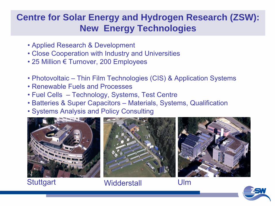
Centre for Solar Energy and Hydrogen Research (ZSW): New Energy Technologies
• Applied Research & Development• Close Cooperation with Industry and Universities•
25 Million €
Turnover, 200 Employees
• Photovoltaic –
Thin Film Technologies (CIS) & Application Systems• Renewable Fuels and Processes• Fuel Cells –
Technology, Systems, Test Centre
• Batteries & Super Capacitors –
Materials, Systems, Qualification• Systems Analysis and Policy Consulting
Stuttgart Widderstall Ulm
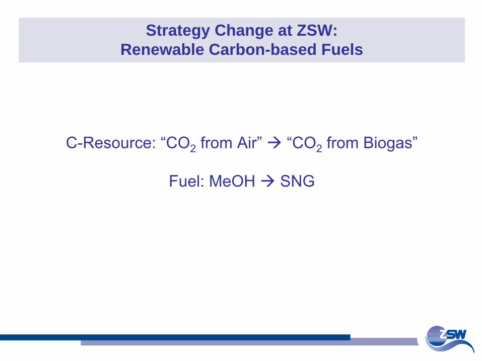
Strategy Change at ZSW: Renewable Carbon-based Fuels
C-Resource: “CO2
from Air” “CO2 from Biogas”
Fuel: MeOH SNG
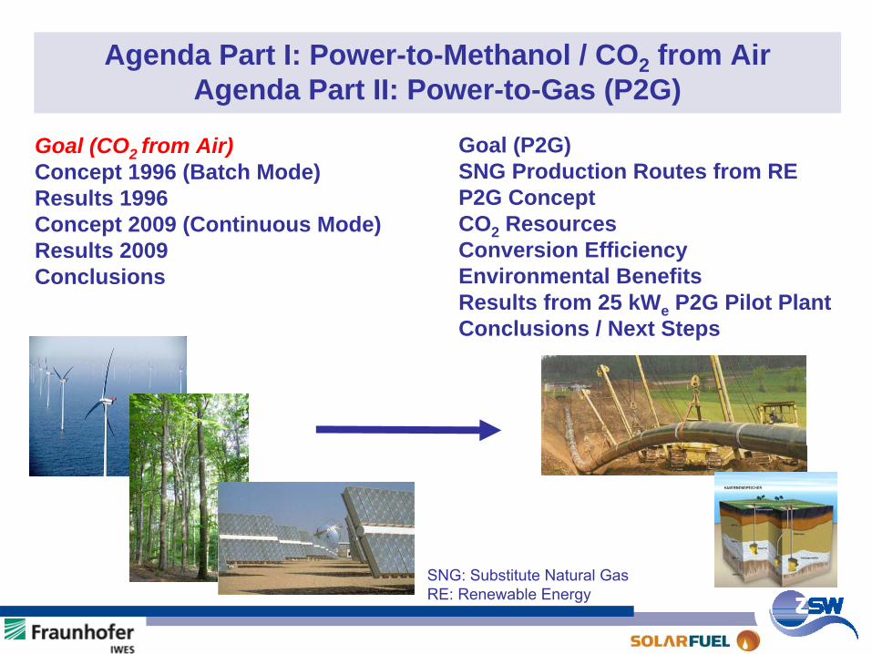
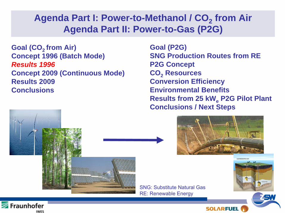
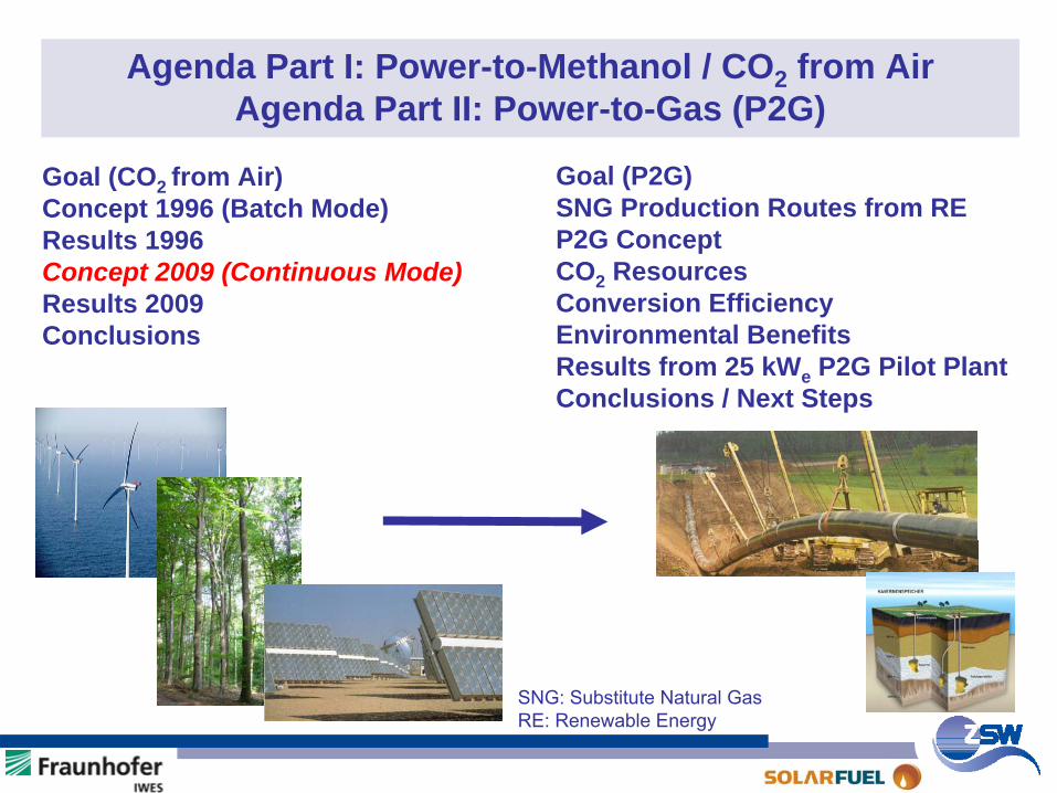
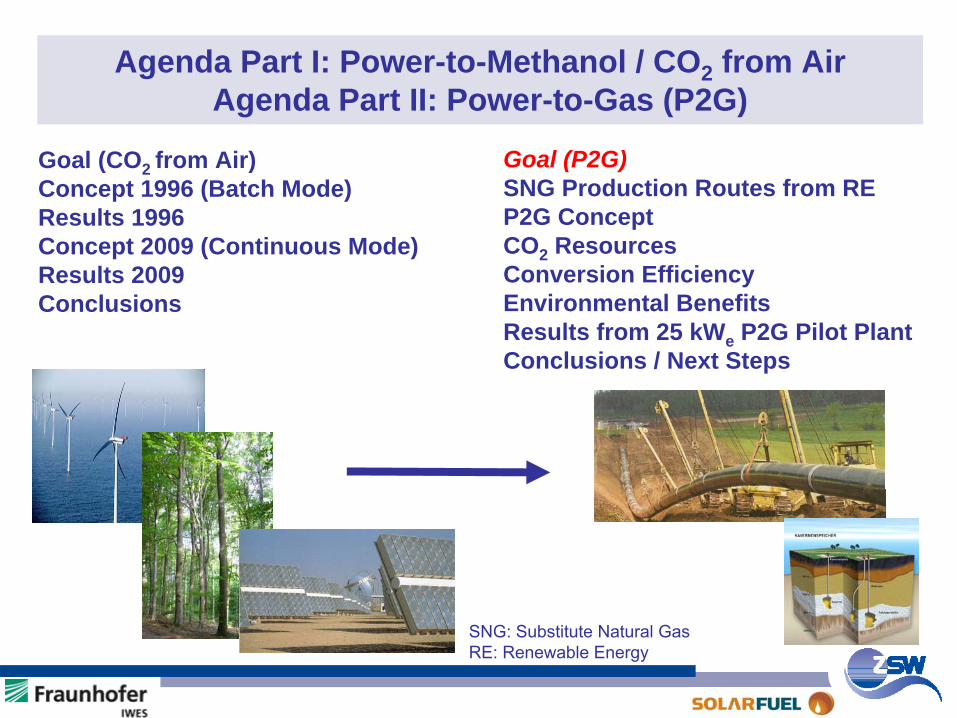
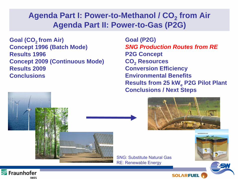
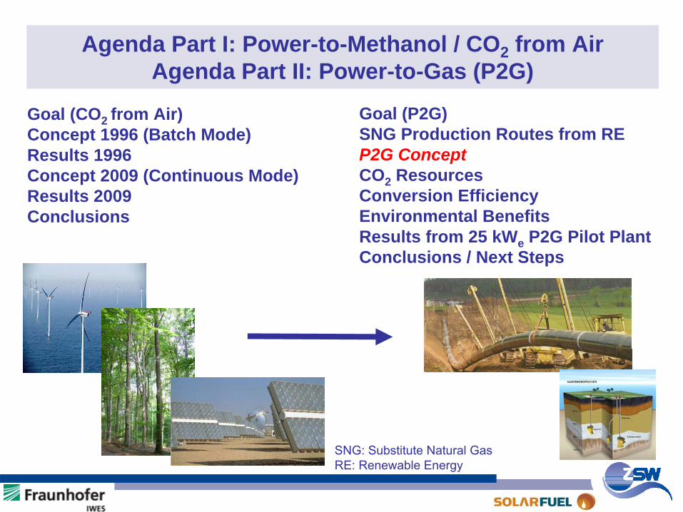
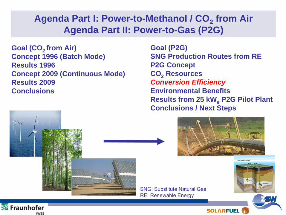
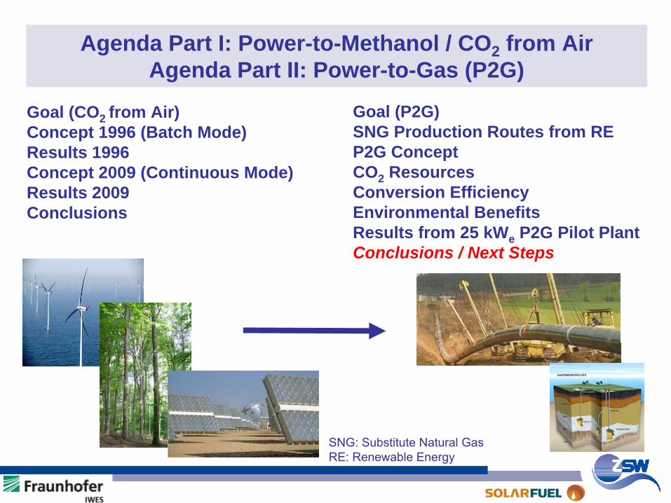
Agenda Part I: Power-to-Methanol / CO2 from Air Agenda Part II: Power-to-Gas (P2G)
Goal (P2G)SNG Production Routes from REP2G ConceptCO2 ResourcesConversion EfficiencyEnvironmental BenefitsResults from 25 kWe P2G Pilot PlantConclusions / Next Steps
SNG: Substitute
Natural
GasRE: Renewable
Energy
Goal (CO2 from Air)Concept 1996 (Batch Mode)Results 1996Concept 2009 (Continuous Mode)Results 2009Conclusions
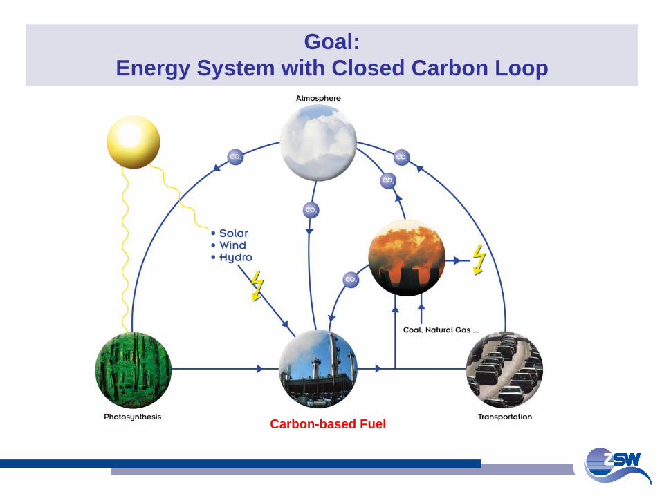
Goal: Energy System with Closed Carbon Loop
Carbon-based Fuel
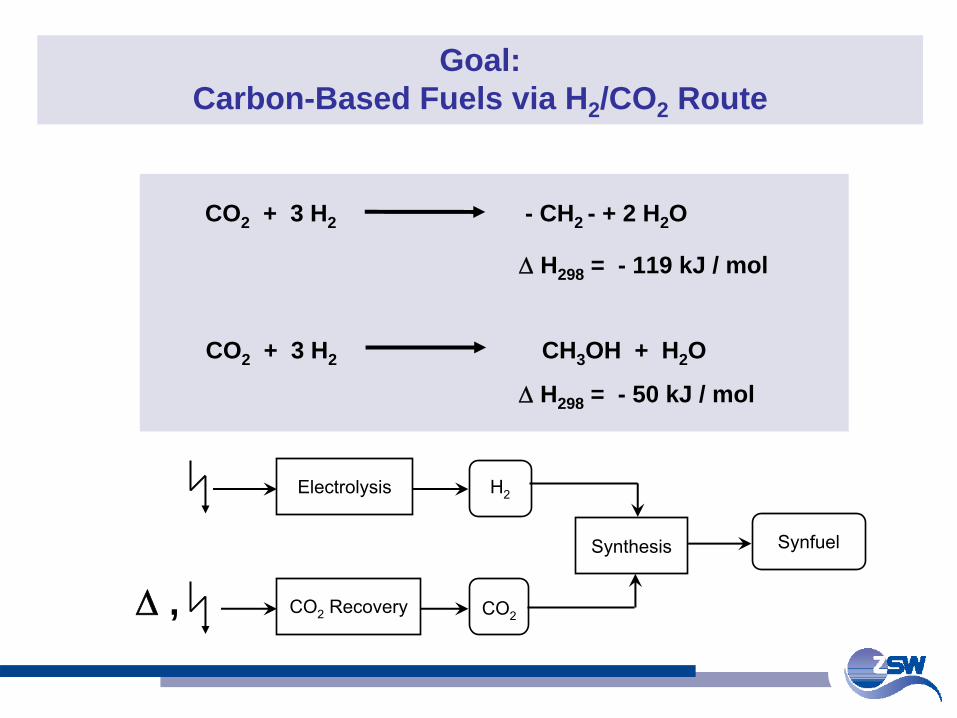
Goal: Carbon-Based Fuels via H2 /CO2 Route
CO2 + 3 H2 - CH2 - + 2 H2 O
Δ
H298 = - 119 kJ / mol
CO2 + 3 H2 CH3 OH + H2 O
Δ
H298 = - 50 kJ / mol
Electrolysis
CO2
Recovery CO2
Synthesis
H2
Synfuel
Δ
,
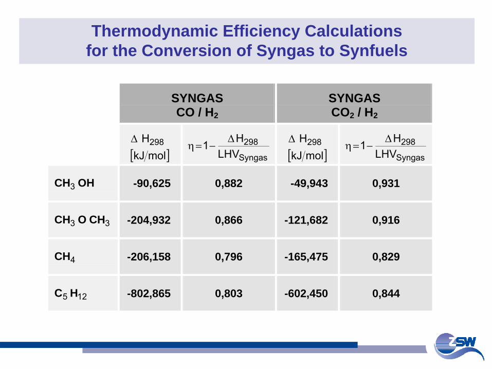
Thermodynamic Efficiency Calculations for the Conversion of Syngas to Synfuels
SYNGAS CO / H2
SYNGAS CO2 / H2
[ ]molkJ
H298Δ
Syngas
298LHV
H1 Δ−=η
[ ]molkJH298Δ
Syngas
298LHV
H1 Δ−=η
OHCH3 -90,625 0,882 -49,943 0,931
33 CHOCH -204,932 0,866 -121,682 0,916
4CH -206,158 0,796 -165,475 0,829
125 HC -802,865 0,803 -602,450 0,844

Agenda Part I: Power-to-Methanol / CO2 from Air Agenda Part II: Power-to-Gas (P2G)
Goal (P2G)SNG Production Routes from REP2G ConceptCO2 ResourcesConversion EfficiencyEnvironmental BenefitsResults from 25 kWe P2G Pilot PlantConclusions / Next Steps
SNG: Substitute
Natural
GasRE: Renewable
Energy
Goal (CO2 from Air)Concept 1996 (Batch Mode)Results 1996Concept 2009 (Continuous Mode)Results 2009Conclusions
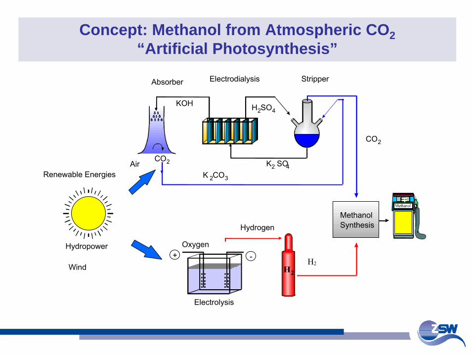
Concept: Methanol from Atmospheric CO2 “Artificial Photosynthesis”
Renewable
Energies
Oxygen
Hydrogen
CO2
CO2
H2
Electrolysis
Absorber Electrodialysis Stripper
MethanolSynthesis
-+
Air
Wind
Hydropower
KOH H2SO4
K2 SO4K 2CO3
H2
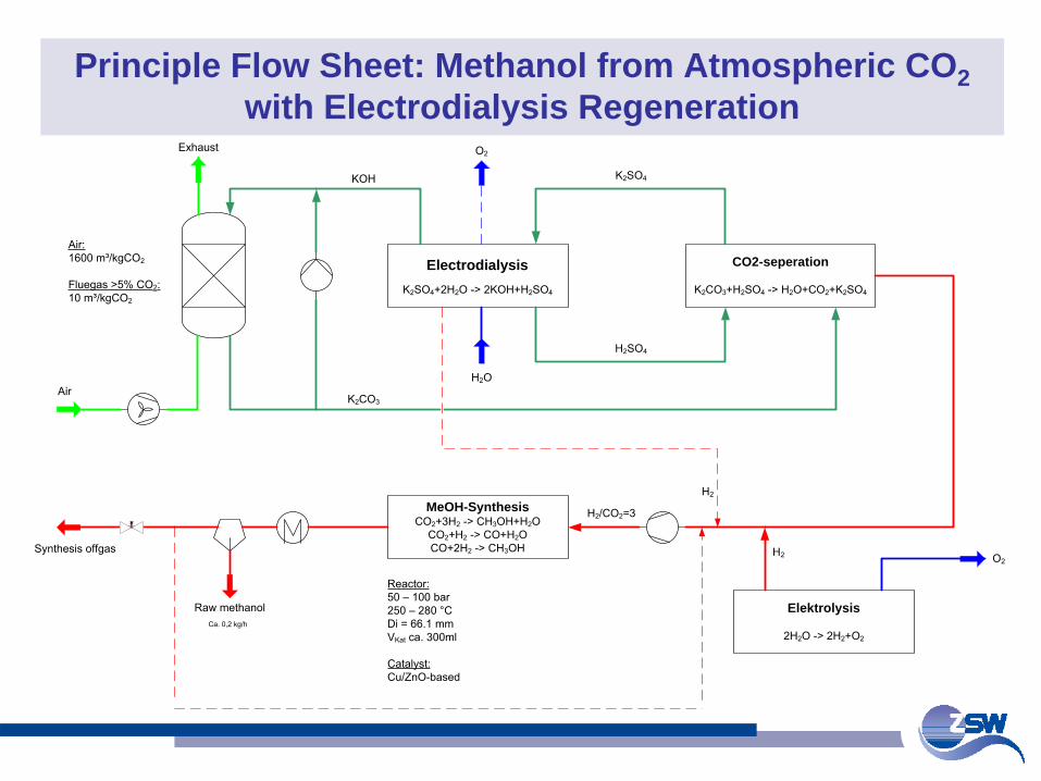
Principle Flow Sheet: Methanol from Atmospheric CO2 with Electrodialysis Regeneration
Dialysis
K2SO4+2H2O -> 2KOH+H2SO4
CO2-seperation
K2CO3+H2SO4 -> H2O+CO2+K2SO4
Exhaust
Air
KOH
K2CO3
H2SO4
K2SO4
H2O
Elektrolysis
2H2O -> 2H2+O2
MeOH-SynthesisCO2+3H2 -> CH3OH+H2O
CO2+H2 -> CO+H2OCO+2H2 -> CH3OH
O2H2
Raw methanol
Synthesis offgas
Reactor:50 – 100 bar 250 – 280 °CDi = 66.1 mmVKat ca. 300ml
Catalyst:Cu/ZnO-based
H2/CO2=3
H2
O2
Air:1600 m³/kgCO2
Fluegas >5% CO2:10 m³/kgCO2
Ca. 0,2 kg/h
Electrodialysis
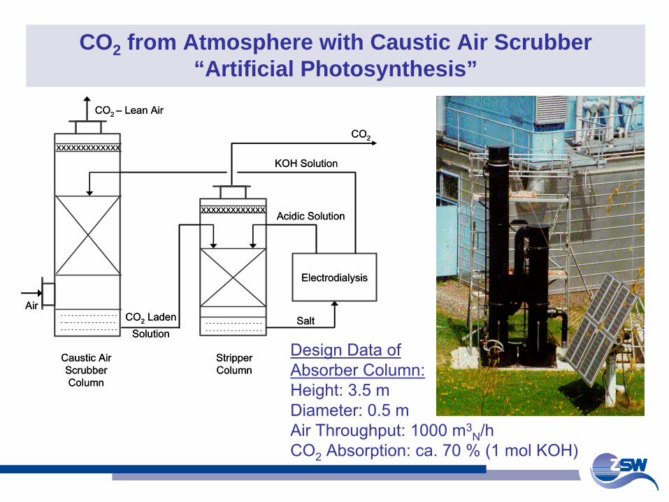
CO2 from Atmosphere with Caustic Air Scrubber “Artificial Photosynthesis”
Caustic Air ScrubberColumn
Stripper Column
XXXXXXXXXXXXX
XXXXXXXXXXXXX
Electrodialysis
Acidic Solution
KOH Solution
CO2
AirSalt
CO2 – Lean Air
- - - - - - - - - - - - - - - -- -- - - - - - - - - - - - - -- - - - - - - - - - - - - - - -
- - - - - - - - - - - - - - - -- - - - - - - - - - - - - - - -
CO2 Laden Solution
Caustic Air ScrubberColumn
Stripper Column
XXXXXXXXXXXXXXXXXXXXXXXXXX
XXXXXXXXXXXXXXXXXXXXXXXXXX
Electrodialysis
Acidic Solution
KOH Solution
CO2
AirSalt
CO2 – Lean Air
- - - - - - - - - - - - - - - -- -- - - - - - - - - - - - - -- - - - - - - - - - - - - - - -
- - - - - - - - - - - - - - - -- - - - - - - - - - - - - - - -
CO2 Laden Solution
Design Data ofAbsorber Column:Height: 3.5 mDiameter: 0.5 mAir Throughput: 1000 m3
N
/hCO2
Absorption: ca. 70 % (1 mol KOH)
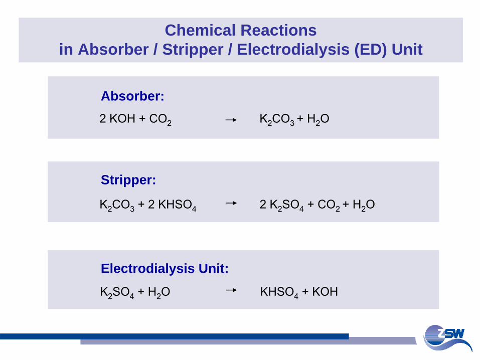
Chemical Reactions in Absorber / Stripper / Electrodialysis (ED) Unit
Absorber:2 KOH + CO2
K2
CO3 + H2
O
Electrodialysis Unit:K2
SO4
+ H2
O KHSO4
+ KOH
Stripper:
K2
CO3
+ 2 KHSO4
2 K2
SO4
+ CO2 + H2
O
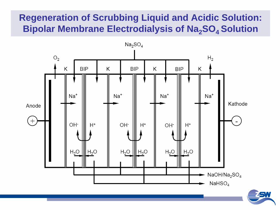
Regeneration of Scrubbing Liquid and Acidic Solution: Bipolar Membrane Electrodialysis of Na2 SO4 Solution
Agenda Part I: Power-to-Methanol / CO2 from Air Agenda Part II: Power-to-Gas (P2G)
Goal (P2G)SNG Production Routes from REP2G ConceptCO2 ResourcesConversion EfficiencyEnvironmental BenefitsResults from 25 kWe P2G Pilot PlantConclusions / Next Steps
SNG: Substitute
Natural
GasRE: Renewable
Energy
Goal (CO2 from Air)Concept 1996 (Batch Mode)Results 1996Concept 2009 (Continuous Mode)Results 2009Conclusions
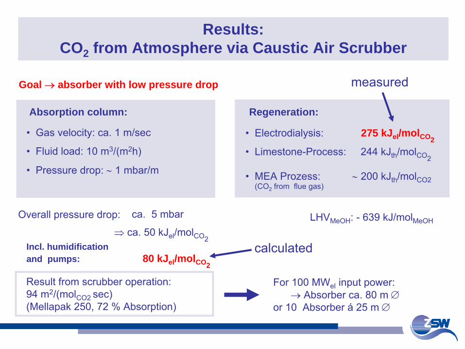
Results: CO2 from Atmosphere via Caustic Air Scrubber
Regeneration:
•
Electrodialysis: 275 kJel /molCO2
•
Limestone-Process: 244 kJth
/molCO2
•
MEA Prozess: ∼
200 kJth
/molCO2
(CO2
from flue gas)
Goal → absorber with low pressure drop
For 100 MWel
input power:→ Absorber ca. 80 m ∅
or 10 Absorber á
25 m ∅
Absorption column:
•
Gas velocity: ca. 1 m/sec
•
Fluid load: 10 m3/(m2h)
•
Pressure drop: ∼
1 mbar/m
Result from scrubber operation:94 m2/(molCO2 sec)(Mellapak
250, 72 % Absorption)
Overall pressure drop: ca. 5 mbar
⇒ ca. 50 kJel
/molCO2Incl. humidificationand pumps: 80 kJel /molCO2
LHVMeOH
: -
639 kJ/molMeOH
calculated
measured
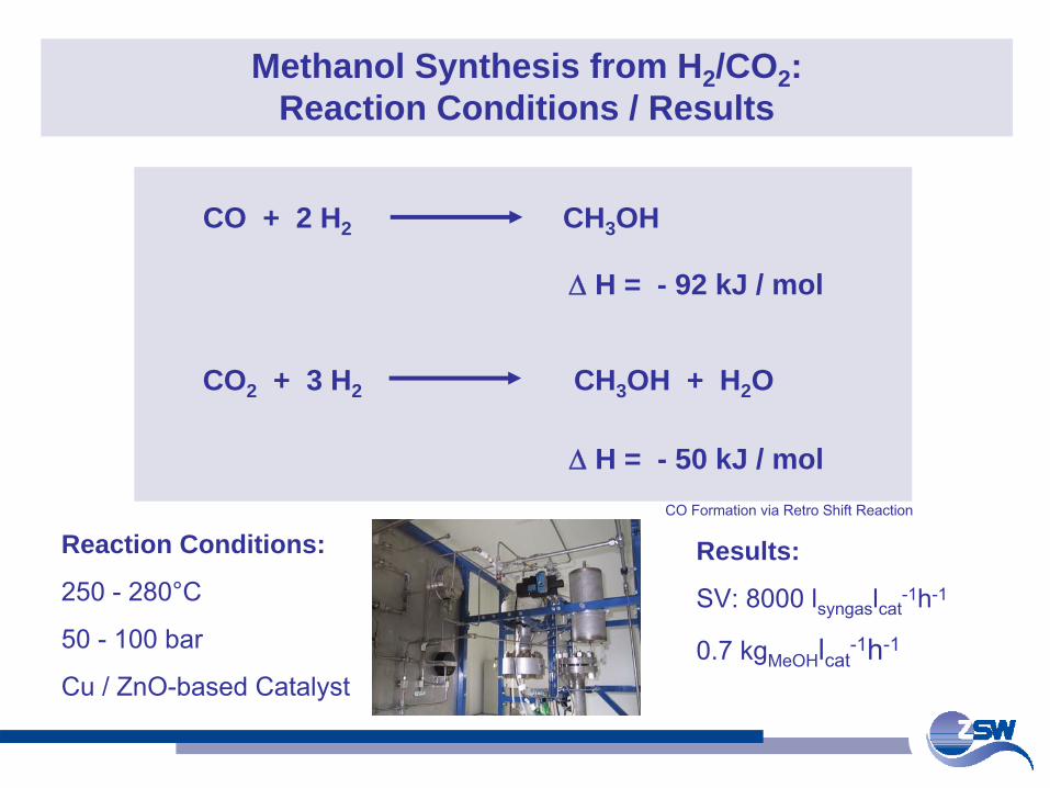
Methanol Synthesis from H2 /CO2 : Reaction Conditions / Results
CO + 2 H2 CH3 OH
Δ
H = - 92 kJ / mol
CO2 + 3 H2 CH3 OH + H2 O
Δ
H = - 50 kJ / mol
Reaction Conditions:
250 -
280°C
50 -
100 bar
Cu / ZnO-based
Catalyst
Results:
SV: 8000 lsyngas
lcat-1h-1
0.7 kgMeOH
lcat-1h-1
CO Formation via Retro Shift Reaction
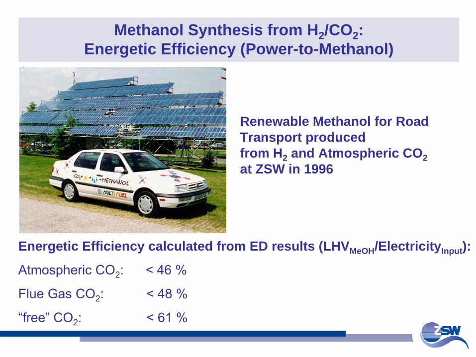
Methanol Synthesis from H2 /CO2 : Energetic Efficiency (Power-to-Methanol)
Energetic Efficiency calculated from ED results (LHVMeOH /ElectricityInput ):
Atmospheric CO2
: < 46 %
Flue Gas CO2
: < 48 %
“free”
CO2
: < 61 %
Renewable Methanol for Road Transport produced from H2 and Atmospheric CO2 at ZSW in 1996
Agenda Part I: Power-to-Methanol / CO2 from Air Agenda Part II: Power-to-Gas (P2G)
Goal (P2G)SNG Production Routes from REP2G ConceptCO2 ResourcesConversion EfficiencyEnvironmental BenefitsResults from 25 kWe P2G Pilot PlantConclusions / Next Steps
SNG: Substitute
Natural
GasRE: Renewable
Energy
Goal (CO2 from Air)Concept 1996 (Batch Mode)Results 1996Concept 2009 (Continuous Mode)Results 2009Conclusions
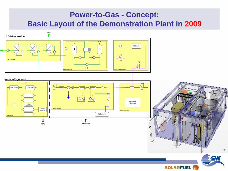
Power-to-Gas - Concept: Basic Layout of the Demonstration Plant in 2009
Abluft
Hydrogen Generator
2-BankKonsole
PKW
CO2-Puffer
Gastrocknung
2-Bank-Speicher
CH4-Puffer
CO2-Produktion
Kraftstoffsynthese
Di-Patrone
Trinkwasser
FIC
PIC
CO2-Absorber
Elektrodialyse CO2-Bereitstellung
H2-ErzeugungCH4-Synthese
FIC
Betankung
PIC
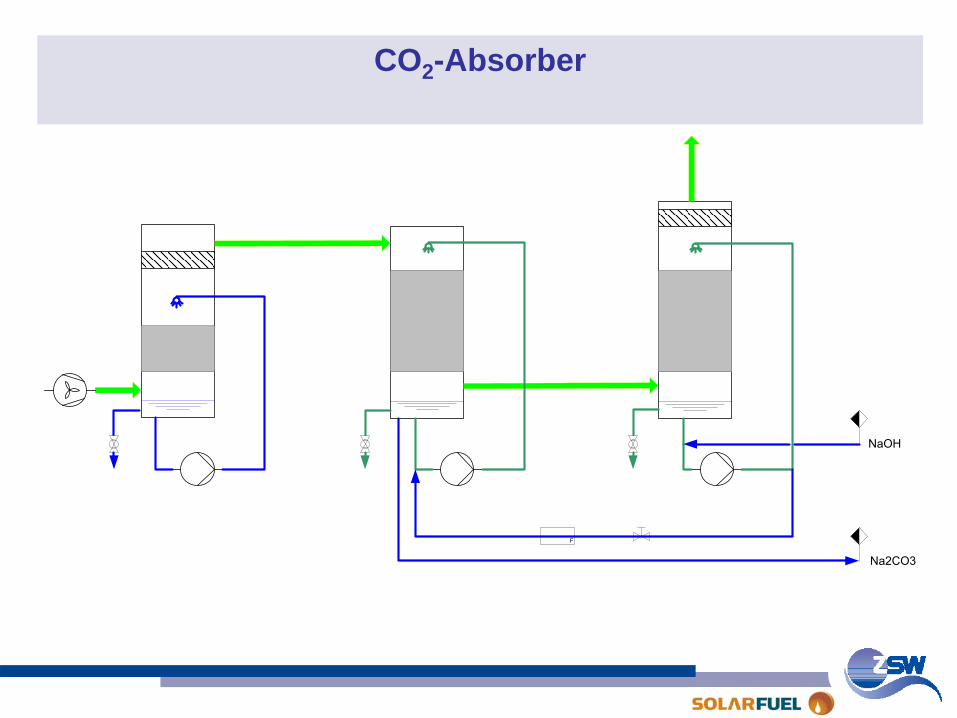
CO2 -Absorber
F
NaOH
Na2CO3
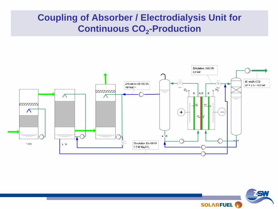
Coupling of Absorber / Electrodialysis Unit for Continuous CO2 -Production
K A K K
+ —
Na+
OH- H+
Na+
H2O2
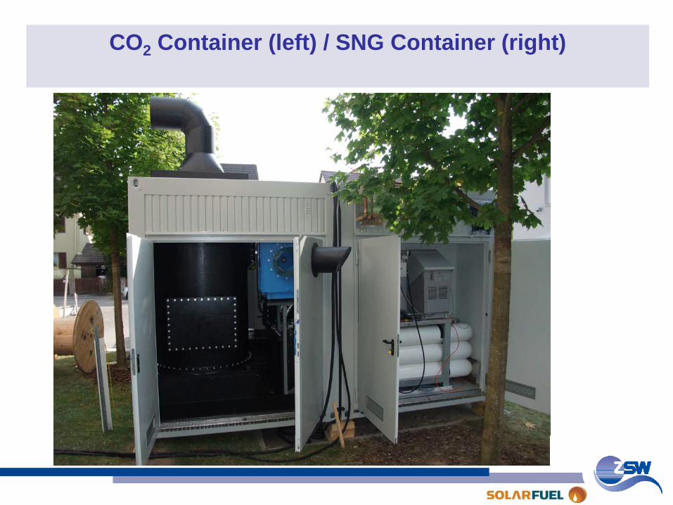
CO2 Container (left) / SNG Container (right)
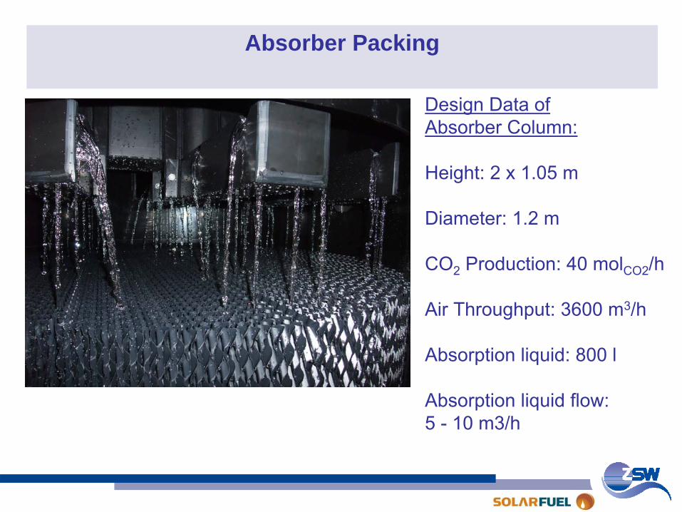
Absorber Packing
Design Data ofAbsorber Column:
Height: 2 x 1.05 m
Diameter: 1.2 m
CO2
Production: 40 molCO2
/h
Air Throughput: 3600 m3/h
Absorption liquid: 800 l
Absorption liquid flow:5 -
10 m3/h
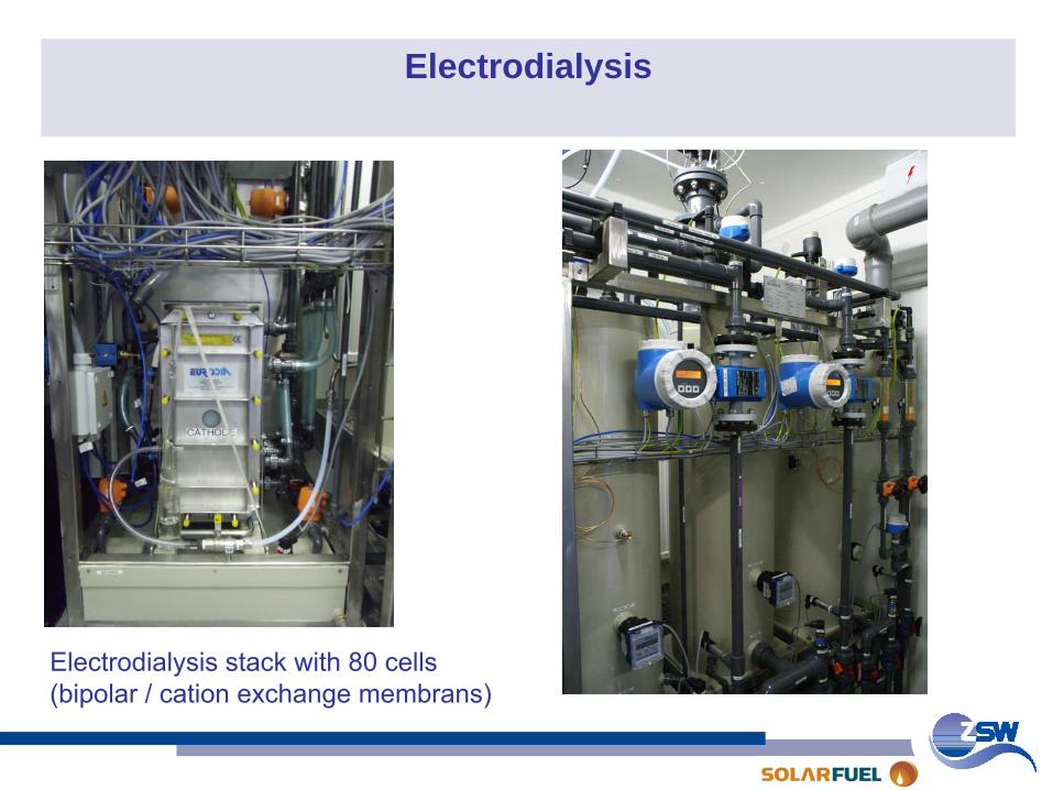
Electrodialysis
Electrodialysis
stack
with
80 cells(bipolar / cation
exchange
membrans)

Agenda Part I: Power-to-Methanol / CO2 from Air Agenda Part II: Power-to-Gas (P2G)
Goal (P2G)SNG Production Routes from REP2G ConceptCO2 ResourcesConversion EfficiencyEnvironmental BenefitsResults from 25 kWe P2G Pilot PlantConclusions / Next Steps
SNG: Substitute
Natural
GasRE: Renewable
Energy
Goal (CO2 from Air)Concept 1996 (Batch Mode)Results 1996Concept 2009 (Continuous Mode)Results 2009Conclusions
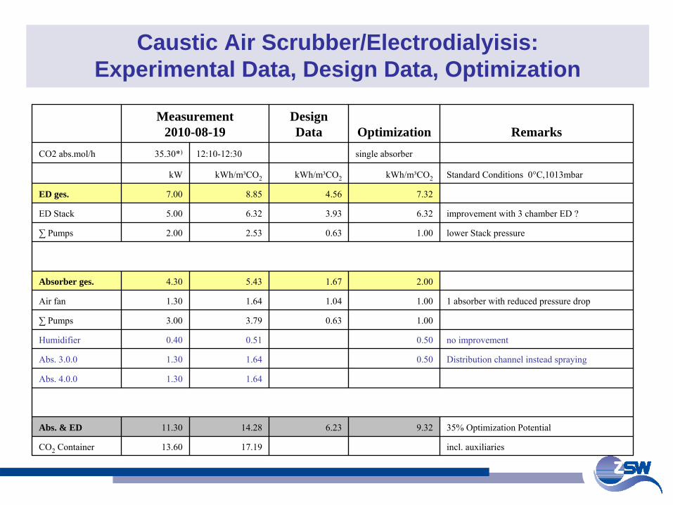
Caustic Air Scrubber/Electrodialyisis: Experimental Data, Design Data, Optimization
Measurement2010-08-19
DesignData Optimization Remarks
CO2 abs.mol/h 35.30*) 12:10-12:30 single absorber
kW kWh/m³CO2 kWh/m³CO2 kWh/m³CO2 Standard Conditions 0°C,1013mbar
ED ges. 7.00 8.85 4.56 7.32
ED Stack 5.00 6.32 3.93 6.32 improvement with 3 chamber ED ?
∑
Pumps 2.00 2.53 0.63 1.00 lower Stack pressure
Absorber ges. 4.30 5.43 1.67 2.00
Air fan 1.30 1.64 1.04 1.00 1 absorber with reduced pressure drop
∑
Pumps 3.00 3.79 0.63 1.00
Humidifier 0.40 0.51 0.50 no improvement
Abs. 3.0.0 1.30 1.64 0.50 Distribution channel instead spraying
Abs. 4.0.0 1.30 1.64
Abs. & ED 11.30 14.28 6.23 9.32 35% Optimization Potential
CO2
Container 13.60 17.19 incl. auxiliaries

Agenda Part I: Power-to-Methanol / CO2 from Air Agenda Part II: Power-to-Gas (P2G)
Goal (P2G)SNG Production Routes from REP2G ConceptCO2 ResourcesConversion EfficiencyEnvironmental BenefitsResults from 25 kWe P2G Pilot PlantConclusions / Next Steps
SNG: Substitute
Natural
GasRE: Renewable
Energy
Goal (CO2 from Air)Concept 1996 (Batch Mode)Results 1996Concept 2009 (Continuous Mode)Results 2009Conclusions
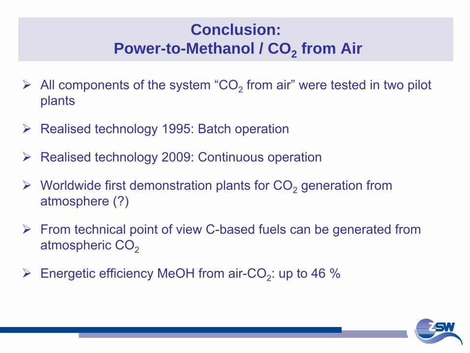
Conclusion: Power-to-Methanol / CO2 from Air
All components of the system “CO2 from air” were tested in two pilot plants
Realised technology 1995: Batch operation
Realised technology 2009: Continuous operation
Worldwide first demonstration plants for CO2 generation from atmosphere (?)
From technical point of view C-based fuels can be generated from atmospheric CO2
Energetic efficiency MeOH from air-CO2: up to 46 %
Agenda Part I: Power-to-Methanol / CO2 from Air Agenda Part II: Power-to-Gas (P2G)
Goal (P2G)SNG Production Routes from REP2G ConceptCO2 ResourcesConversion EfficiencyEnvironmental BenefitsResults from 25 kWe P2G Pilot PlantConclusions / Next Steps
SNG: Substitute
Natural
GasRE: Renewable
Energy
Goal (CO2 from Air)Concept 1996 (Batch Mode)Results 1996Concept 2009 (Continuous Mode)Results 2009Conclusions
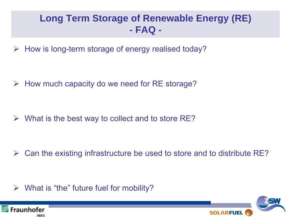
Long Term Storage of Renewable Energy (RE) - FAQ -
How is long-term storage of energy realised today?
How much capacity do we need for RE storage?
What is the best way to collect and to store RE?
Can the existing infrastructure be used to store and to distribute RE?
What is “the” future fuel for mobility?
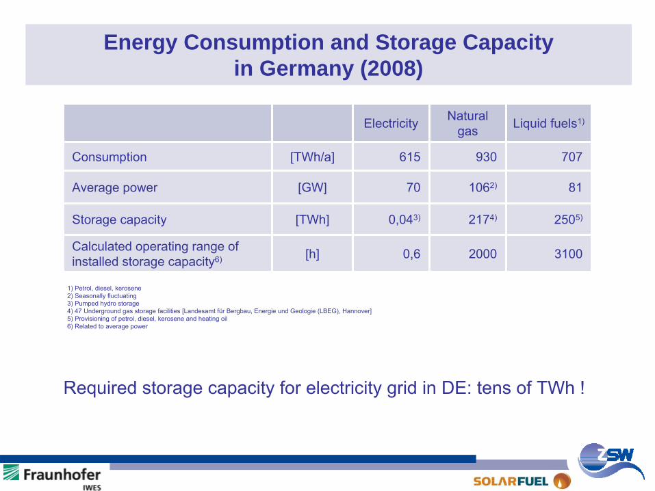
Energy Consumption and Storage Capacity in Germany (2008)
Electricity Natural gas Liquid fuels1)
Consumption [TWh/a] 615 930 707
Average power [GW] 70 1062) 81
Storage capacity [TWh] 0,043) 2174) 2505)
Calculated operating range of installed storage capacity6) [h] 0,6 2000 3100
1) Petrol, diesel, kerosene2) Seasonally fluctuating3) Pumped hydro storage4) 47 Underground gas storage facilities [Landesamt
für
Bergbau, Energie
und Geologie
(LBEG), Hannover]5) Provisioning of petrol, diesel, kerosene and heating oil6) Related to average power
Required storage capacity for electricity grid in DE: tens of TWh
!
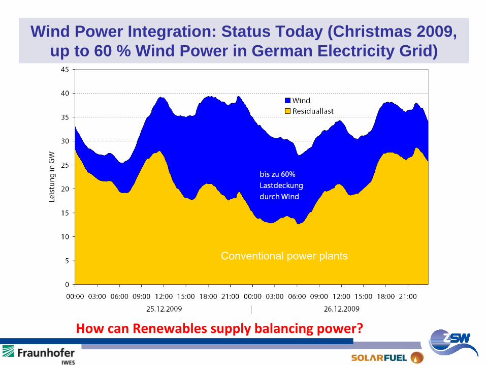
Wind Power Integration: Status Today (Christmas 2009, up to 60 % Wind Power in German Electricity Grid)
How can Renewables
supply balancing power?
Conventional power plants
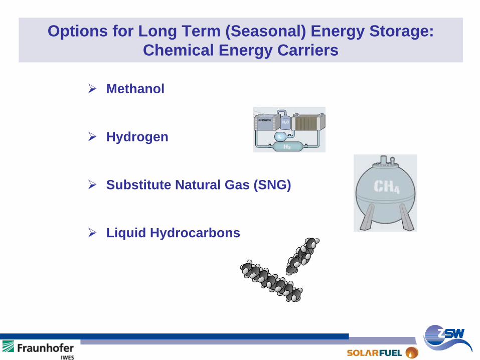
Options for Long Term (Seasonal) Energy Storage: Chemical Energy Carriers
Methanol
Hydrogen
Substitute Natural Gas (SNG)
Liquid Hydrocarbons
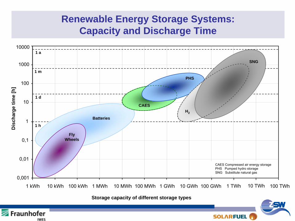
Renewable Energy Storage Systems: Capacity and Discharge Time
0,001
0,01
0,1
1
10
100
1000
10000
1 kWh 10 kWh 100 kWh 1 MWh 10 MWh 100 MWh 1 GWh 10 GWh 100 GWh
1 m
1 h
1 d
CAES
1 TWh 10 TWh 100 TWh
CAES
Fly Wheels
Storage capacity of different storage types
Dis
char
ge ti
me
[h]
CAES Compressed
air
energy
storage
PHS Pumped
hydro
storage
SNG Substitute
natural
gas
Batteries
PHS
1 a
SNG
H2
Agenda Part I: Power-to-Methanol / CO2 from Air Agenda Part II: Power-to-Gas (P2G)
Goal (P2G)SNG Production Routes from REP2G ConceptCO2 ResourcesConversion EfficiencyEnvironmental BenefitsResults from 25 kWe P2G Pilot PlantConclusions / Next Steps
SNG: Substitute
Natural
GasRE: Renewable
Energy
Goal (CO2 from Air)Concept 1996 (Batch Mode)Results 1996Concept 2009 (Continuous Mode)Results 2009Conclusions
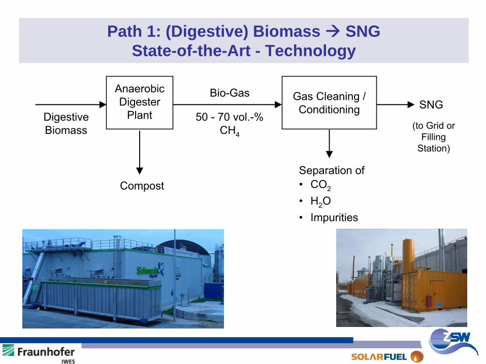
Path 1: (Digestive) Biomass SNG State-of-the-Art - Technology
AnaerobicDigester
Plant
Gas Cleaning /Conditioning
Bio-Gas
50 - 70 vol.-%CH4
DigestiveBiomass
Compost
SNG
Separation of• CO2
• H2O• Impurities
(to Grid orFilling
Station)
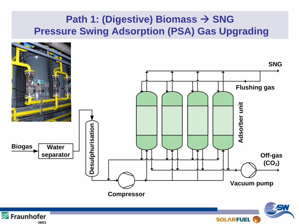
Path 1: (Digestive) Biomass SNGPressure Swing Adsorption (PSA) Gas Upgrading
Biogas
Vacuum pump
Off-gas(CO2)
Flushing gas
SNG
Water separator
Compressor
Des
ulph
uris
atio
n
Ads
orbe
r uni
t
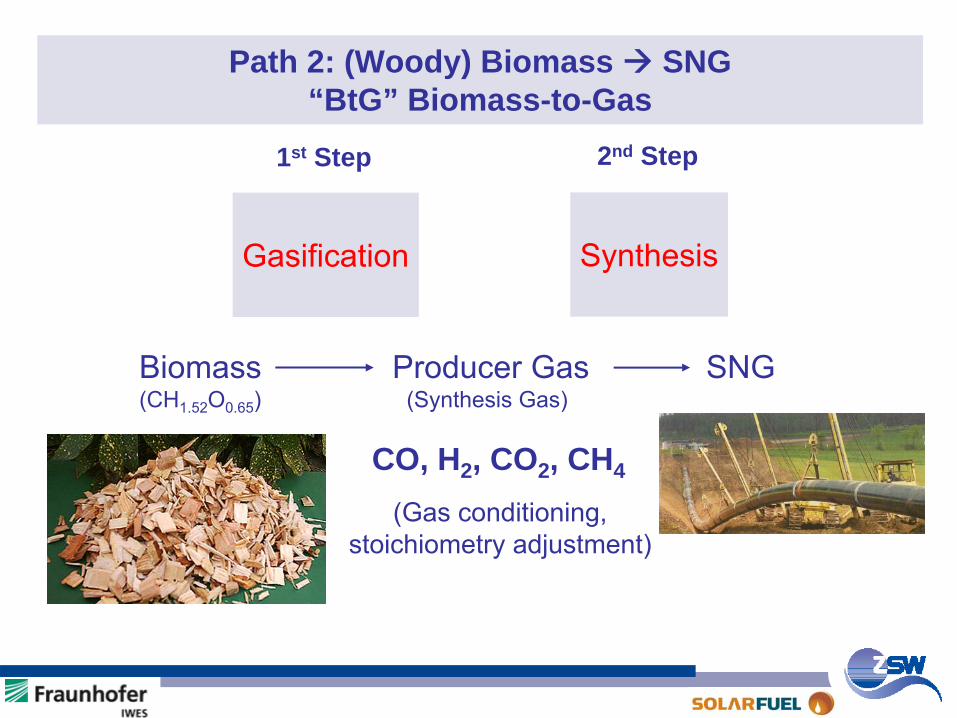
Path 2: (Woody) Biomass SNG“BtG” Biomass-to-Gas
CO, H2 , CO2 , CH4
Gasification
Biomass
Producer Gas
SNG(CH1.52
O0.65
)
(Synthesis Gas)
(Gas conditioning,stoichiometry
adjustment)
1st Step 2nd Step
Synthesis
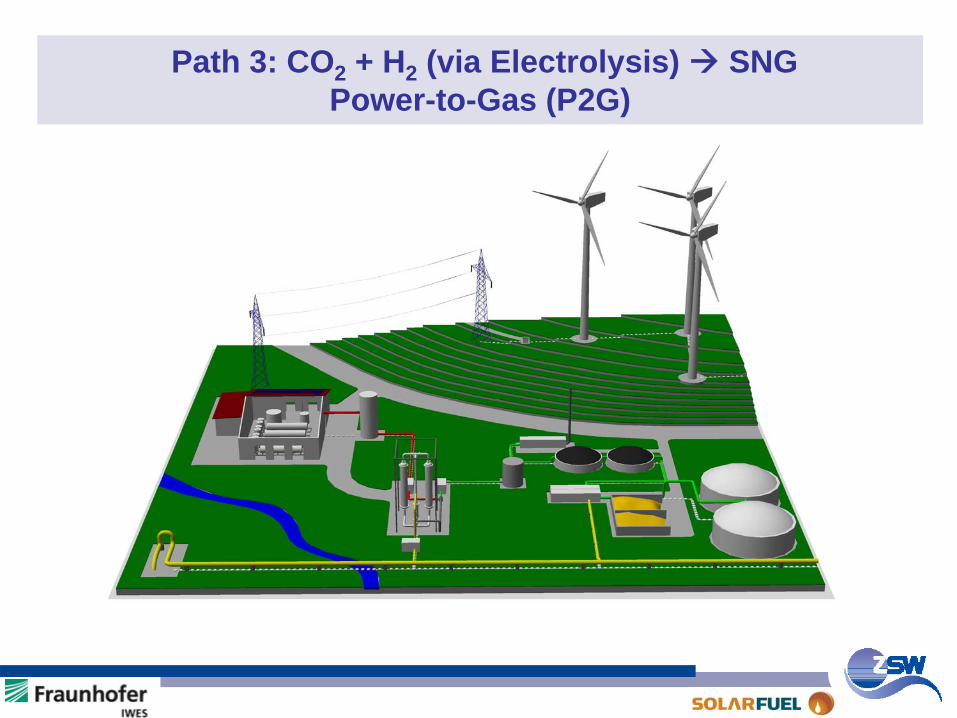
Path 3: CO2 + H2 (via Electrolysis) SNGPower-to-Gas (P2G)
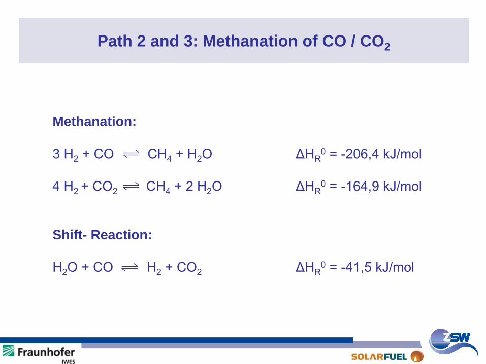
Path 2 and 3: Methanation of CO / CO2
Methanation:
3 H2
+ CO CH4
+ H2
O ΔHR0
= -206,4 kJ/mol
4 H2 + CO2 CH4
+ 2 H2
O ΔHR0
= -164,9 kJ/mol
Shift- Reaction:
H2
O + CO H2
+ CO2
ΔHR0
= -41,5 kJ/mol
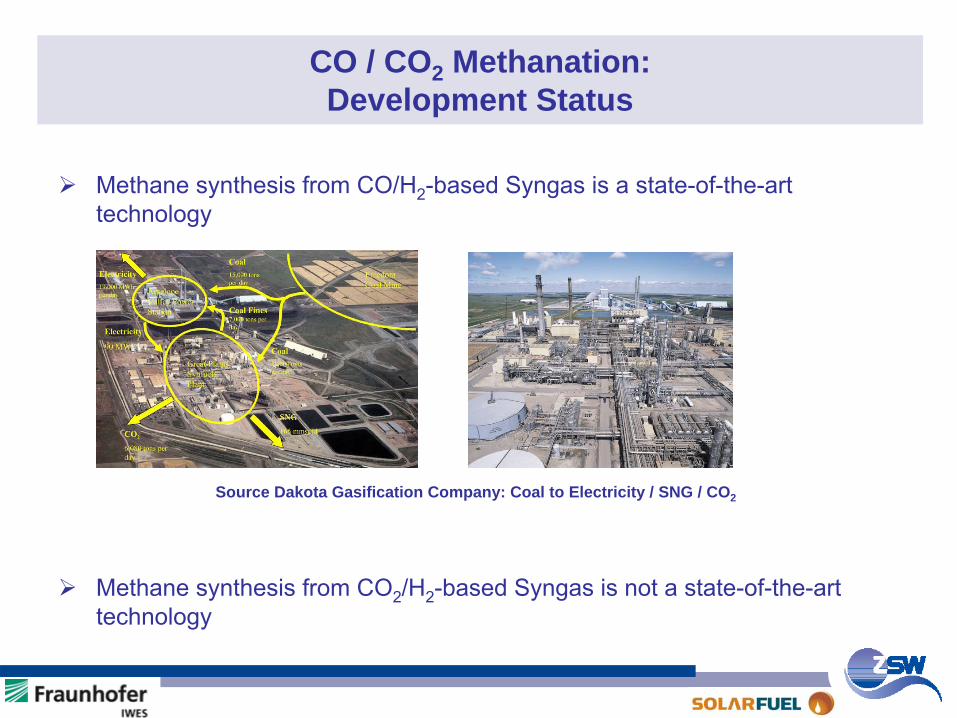
CO / CO2 Methanation: Development Status
Methane synthesis from CO/H2-based Syngas is a state-of-the-art technology
Methane synthesis from CO2/H2-based Syngas is not a state-of-the-art technology
Source Dakota Gasification Company: Coal to Electricity / SNG / CO2
Agenda Part I: Power-to-Methanol / CO2 from Air Agenda Part II: Power-to-Gas (P2G)
Goal (P2G)SNG Production Routes from REP2G ConceptCO2 ResourcesConversion EfficiencyEnvironmental BenefitsResults from 25 kWe P2G Pilot PlantConclusions / Next Steps
SNG: Substitute
Natural
GasRE: Renewable
Energy
Goal (CO2 from Air)Concept 1996 (Batch Mode)Results 1996Concept 2009 (Continuous Mode)Results 2009Conclusions
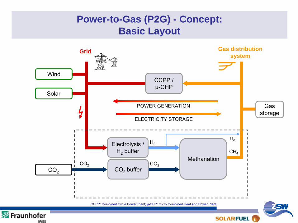
Power-to-Gas (P2G) - Concept: Basic Layout
CCPP / µ-CHP
CO2
buffer
Grid Gas distribution system
Electrolysis /
H2
bufferMethanation
H2
CO2
CH4
POWER GENERATION
ELECTRICITY STORAGE
CO2
Gas
storage
Solar
Wind
H2
CO2
CCPP: Combined Cycle Power Plant; µ-CHP: micro Combined Heat and Power Plant
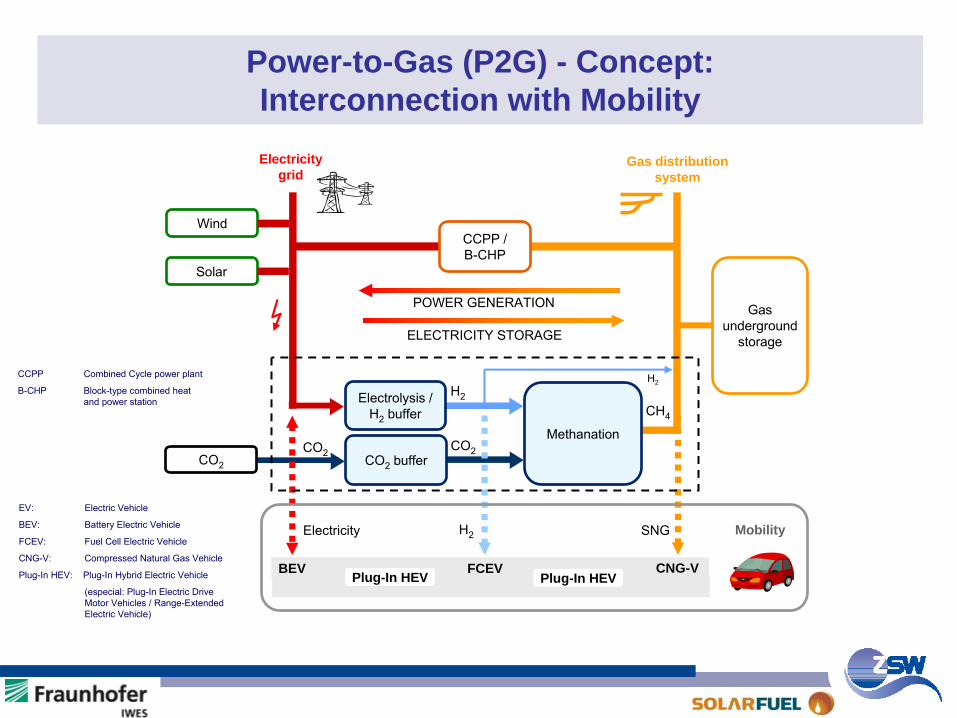
Power-to-Gas (P2G) - Concept: Interconnection with Mobility
EV:
Electric Vehicle
BEV: Battery Electric Vehicle
FCEV: Fuel Cell Electric Vehicle
CNG-V: Compressed Natural Gas Vehicle
Plug-In HEV: Plug-In Hybrid Electric Vehicle
(especial: Plug-In Electric Drive Motor Vehicles / Range-Extended Electric Vehicle)
CCPP Combined
Cycle
power plant
B-CHP Block-type combined heat and power station
Solar
WindCCPP / B-CHP
CO2
buffer
Electricitygrid
Gas distribution system
Electrolysis
/
H2
bufferMethanation
H2
CO2
CH4
POWER GENERATION
ELECTRICITY STORAGE
CO2
Gas
underground
storage
Electricity H2 SNG
BEV FCEV CNG-V
Mobility
H2
CO2
Plug-In HEV Plug-In HEV

Agenda Part I: Power-to-Methanol / CO2 from Air Agenda Part II: Power-to-Gas (P2G)
Goal (P2G)SNG Production Routes from REP2G ConceptCO2 ResourcesConversion EfficiencyEnvironmental BenefitsResults from 25 kWe P2G Pilot PlantConclusions / Next Steps
SNG: Substitute
Natural
GasRE: Renewable
Energy
Goal (CO2 from Air)Concept 1996 (Batch Mode)Results 1996Concept 2009 (Continuous Mode)Results 2009Conclusions

Utilisation of Biogenic CO2 Resources for P2G-Process
C6 H12 O6 3 CH4 + 3 CO2
Simplified overall reaction
C6 H12 O6 2 C2 H5OH + 2 CO2
Biogas production:
Ethanol production:
Biogas plant, Foto: Krautkremer
EtOH
plant in Nebraska, USA
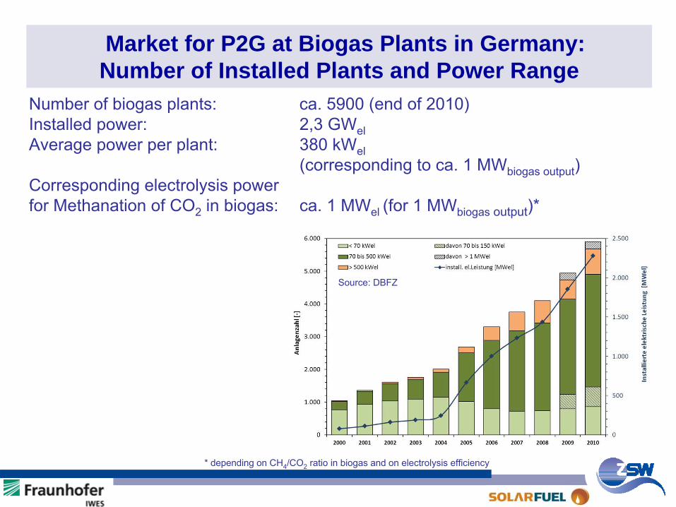
Market for P2G at Biogas Plants in Germany: Number of Installed Plants and Power Range
Source: DBFZ
Number of biogas plants:
ca. 5900 (end of 2010)Installed power: 2,3 GWelAverage power per plant: 380 kWel
(corresponding to ca. 1 MWbiogas
output
)Corresponding electrolysis power for Methanation
of CO2
in biogas: ca. 1 MWel
(for 1 MWbiogas
output
)*
* depending
on CH4
/CO2
ratio
in biogas
and on electrolysis
efficiency
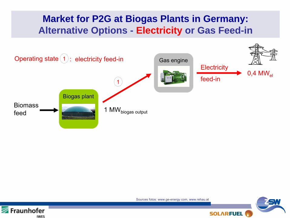
Market for P2G at Biogas Plants in Germany: Alternative Options - Electricity or Gas Feed-in
Biomass
feed
Electricity
feed-in0,4 MWel
Biogas plant
Gas engine
1
1 MWbiogas
output
Operating state 1 : electricity feed-in
Sources fotos: www.ge-energy.com, www.rehau.at
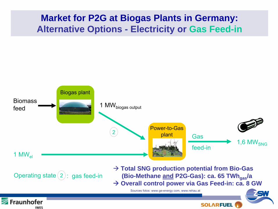
Market for P2G at Biogas Plants in Germany: Alternative Options - Electricity or Gas Feed-in
Biomass
feed
Gas
feed-in1,6 MWSNG
Biogas plant
Power-to-Gas plant
1 MWel
2
Operating state 2 : gas feed-in
1 MWbiogas
output
Sources fotos: www.ge-energy.com, www.rehau.at
Total SNG production potential from Bio-Gas (Bio-Methane and P2G-Gas): ca. 65 TWhgas /aOverall control power via Gas Feed-in: ca. 8 GW
Agenda Part I: Power-to-Methanol / CO2 from Air Agenda Part II: Power-to-Gas (P2G)
Goal (P2G)SNG Production Routes from REP2G ConceptCO2 ResourcesConversion EfficiencyEnvironmental BenefitsResults from 25 kWe P2G Pilot PlantConclusions / Next Steps
SNG: Substitute
Natural
GasRE: Renewable
Energy
Goal (CO2 from Air)Concept 1996 (Batch Mode)Results 1996Concept 2009 (Continuous Mode)Results 2009Conclusions
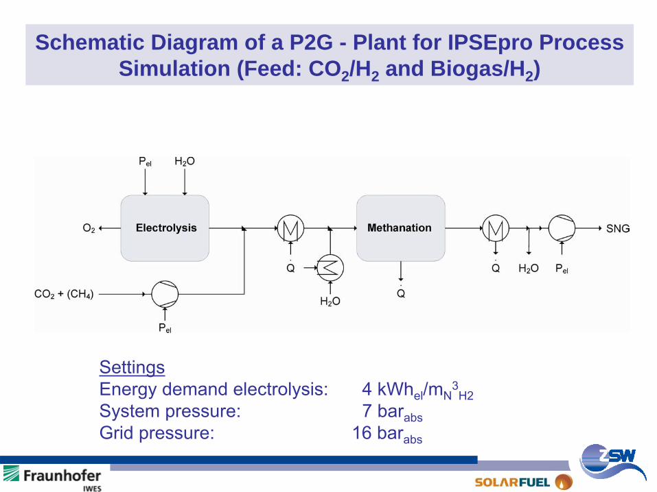
Schematic Diagram of a P2G - Plant for IPSEpro Process Simulation (Feed: CO2 /H2 and Biogas/H2 )
SettingsEnergy demand electrolysis:
4 kWhel
/mN3H2
System pressure:
7 barabsGrid pressure:
16 barabs
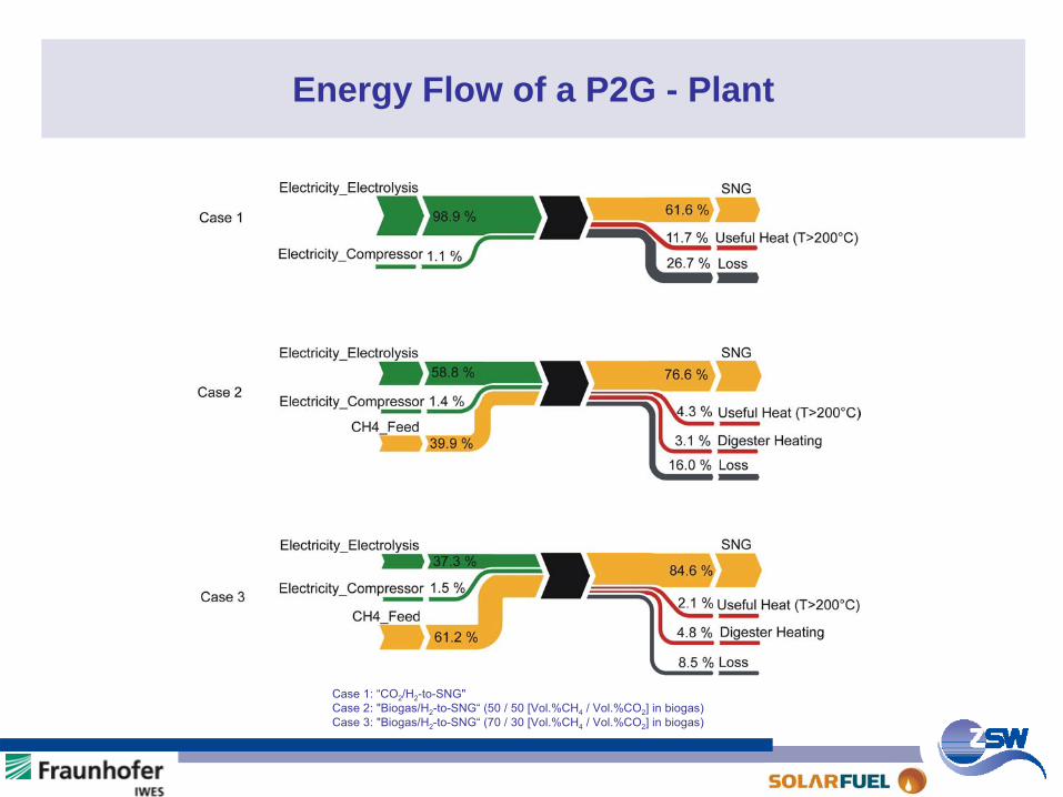
Energy Flow of a P2G - Plant
Case
1: “CO2
/H2
-to-SNG"Case
2: "Biogas/H2
-to-SNG“
(50 / 50 [Vol.%CH4
/ Vol.%CO2
] in biogas)Case
3: "Biogas/H2
-to-SNG“
(70 / 30 [Vol.%CH4
/ Vol.%CO2
] in biogas)
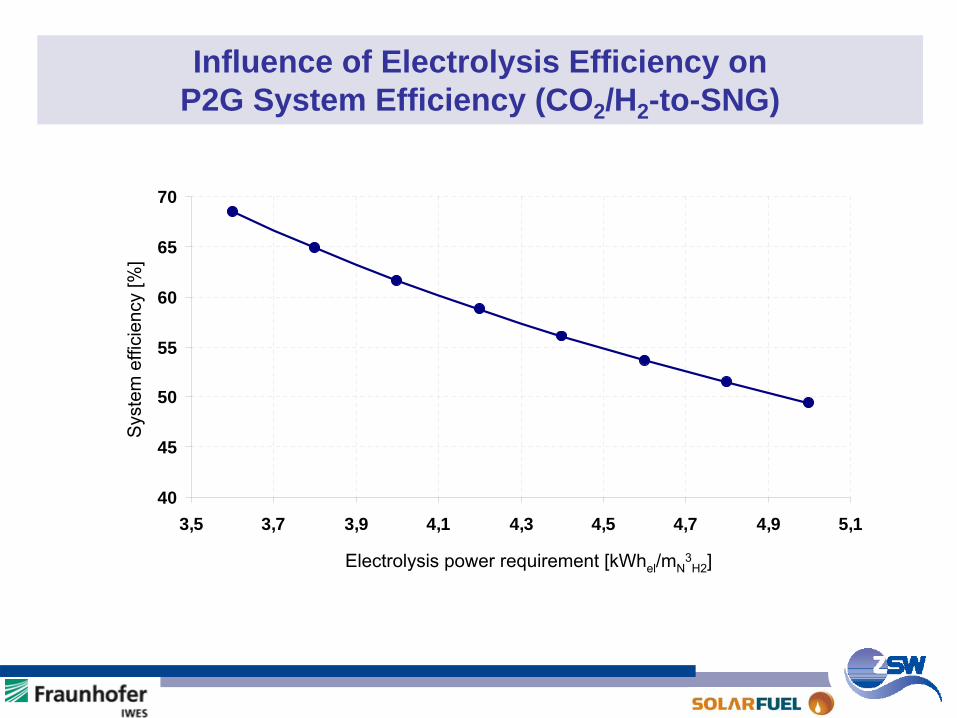
Influence of Electrolysis Efficiency on P2G System Efficiency (CO2 /H2 -to-SNG)
40
45
50
55
60
65
70
3,5 3,7 3,9 4,1 4,3 4,5 4,7 4,9 5,1
Electrolysis power requirement [kWhel
/mN3H2
]
Sys
tem
effi
cien
cy [%
]

Agenda Part I: Power-to-Methanol / CO2 from Air Agenda Part II: Power-to-Gas (P2G)
Goal (P2G)SNG Production Routes from REP2G ConceptCO2 ResourcesConversion EfficiencyEnvironmental BenefitsResults from 25 kWe P2G Pilot PlantConclusions / Next Steps
SNG: Substitute
Natural
GasRE: Renewable
Energy
Goal (CO2 from Air)Concept 1996 (Batch Mode)Results 1996Concept 2009 (Continuous Mode)Results 2009Conclusions
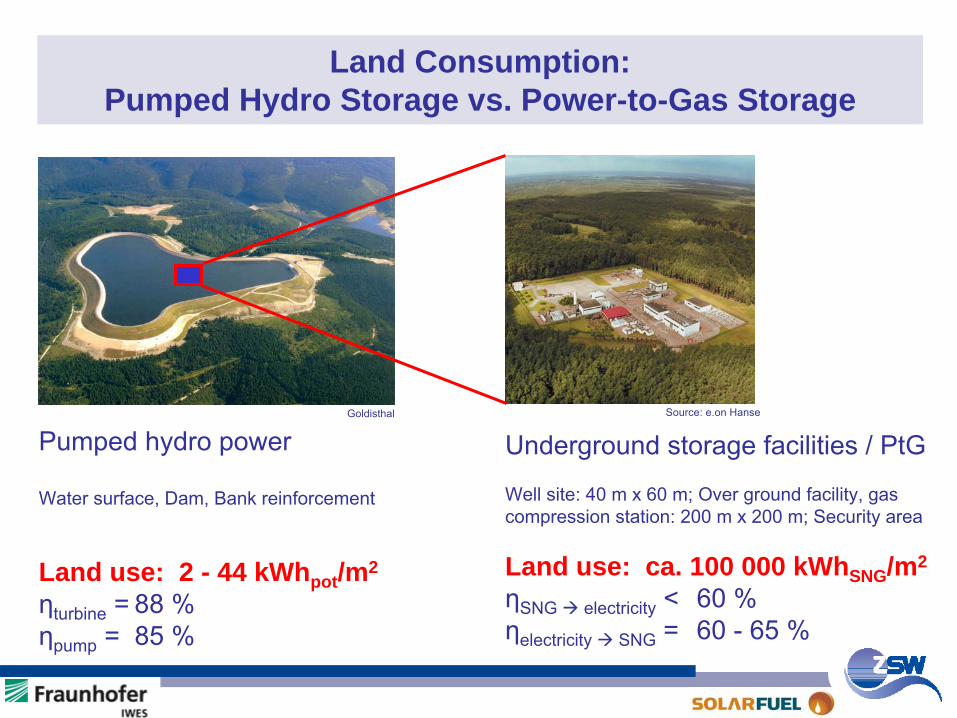
Land Consumption: Pumped Hydro Storage vs. Power-to-Gas Storage
Goldisthal Source: e.on
Hanse
Pumped hydro power
Water surface, Dam, Bank reinforcement
Land use: 2 - 44 kWhpot /m2
ηturbine
=
88 %ηpump
= 85 %
Underground storage facilities / PtG
Well site: 40 m x 60 m; Over ground facility, gas compression station: 200 m x 200 m; Security area
Land use: ca. 100 000 kWhSNG /m2
ηSNG electricity < 60 %ηelectricity SNG = 60 - 65 %
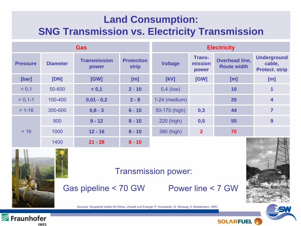
Land Consumption: SNG Transmission vs. Electricity Transmission
Sources: Wuppertal Institut
für
Klima, Umwelt
und Energie; P. Konstantin; G. Wossog; H. Brakelmann; OMV
Gas Electricity
Pressure Diameter Transmission power
Protection strip Voltage
Trans- mission power
Overhead line, Route width
Underground cable,
Protect. strip
[bar] [DN] [GW] [m] [kV] [GW] [m] [m]
< 0,1 50-600 < 0,1 2 - 10 0,4 (low) 10 1
> 0,1-1 100-400 0,01 - 0,2 2 - 8 1-24 (medium) 20 4
> 1-16 300-600 0,8 - 3 6 - 10 50-170 (high) 0,3 44 7
> 16
900 9 - 12 8 - 10 220 (high) 0,5 55 9
1000 12 - 16 8 - 10 380 (high) 2 70
1400 21 - 28 8 - 10
Transmission power:
Gas pipeline < 70 GW Power line < 7 GW
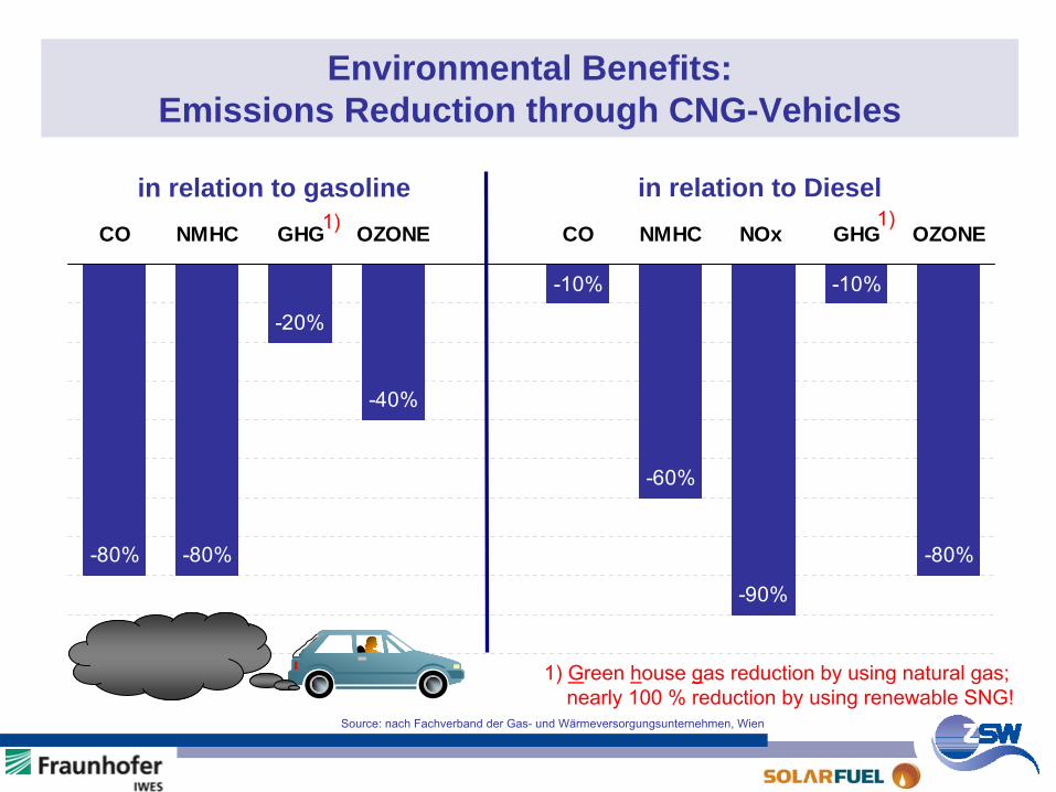
Environmental Benefits: Emissions Reduction through CNG-Vehicles
-80% -80%
-20%
-40%
-10%
-60%
-90%
-10%
-80%
CO NMHC GHG OZONE CO NMHC NOx GHG OZONE
in relation to gasoline in relation to Diesel
Source: nach
Fachverband
der
Gas-
und Wärmeversorgungsunternehmen, Wien
1) 1)
1) Green house gas reduction by using natural gas;nearly 100 % reduction by using renewable SNG!
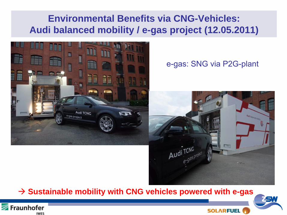
Environmental Benefits via CNG-Vehicles: Audi balanced mobility / e-gas project (12.05.2011)
Sustainable mobility with CNG vehicles powered with e-gas
e-gas: SNG via P2G-plant

Agenda Part I: Power-to-Methanol / CO2 from Air Agenda Part II: Power-to-Gas (P2G)
Goal (P2G)SNG Production Routes from REP2G ConceptCO2 ResourcesConversion EfficiencyEnvironmental BenefitsResults from 25 kWe P2G Pilot PlantConclusions / Next Steps
SNG: Substitute
Natural
GasRE: Renewable
Energy
Goal (CO2 from Air)Concept 1996 (Batch Mode)Results 1996Concept 2009 (Continuous Mode)Results 2009Conclusions
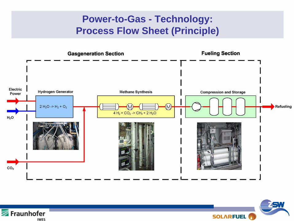
Power-to-Gas - Technology: Process Flow Sheet (Principle)
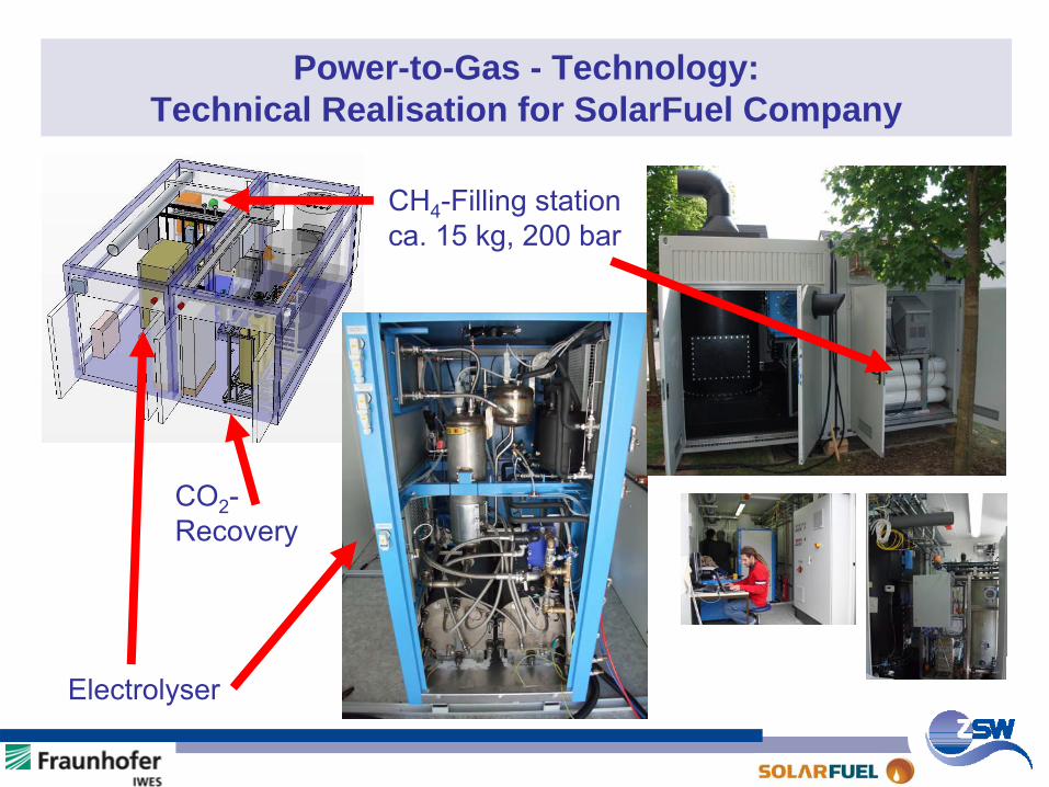
Power-to-Gas - Technology: Technical Realisation for SolarFuel Company
CH4
-Filling stationca. 15 kg, 200 bar
Electrolyser
CO2
-Recovery
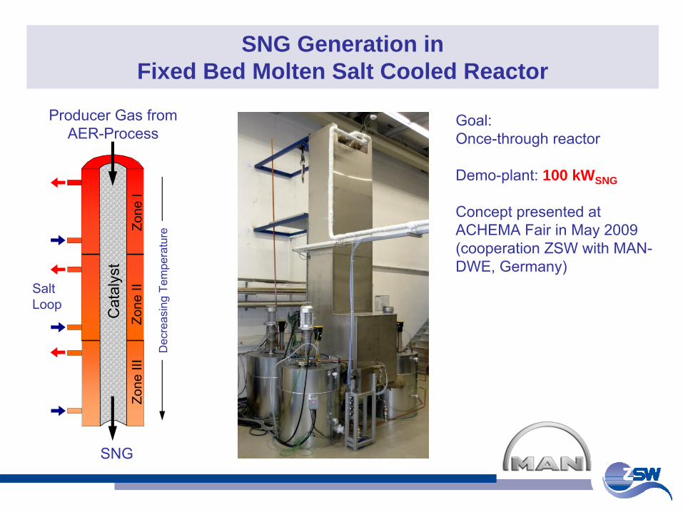
SNG Generation in Fixed Bed Molten Salt Cooled Reactor
SNG
Producer Gas from AER-Process
Salt Loop C
atal
yst
Zone
IZo
ne II
Zone
III
Dec
reas
ing
Tem
pera
ture
Goal:Once-through reactor
Demo-plant: 100 kWSNG
Concept presented at ACHEMA Fair in May 2009 (cooperation ZSW with MAN-
DWE, Germany)
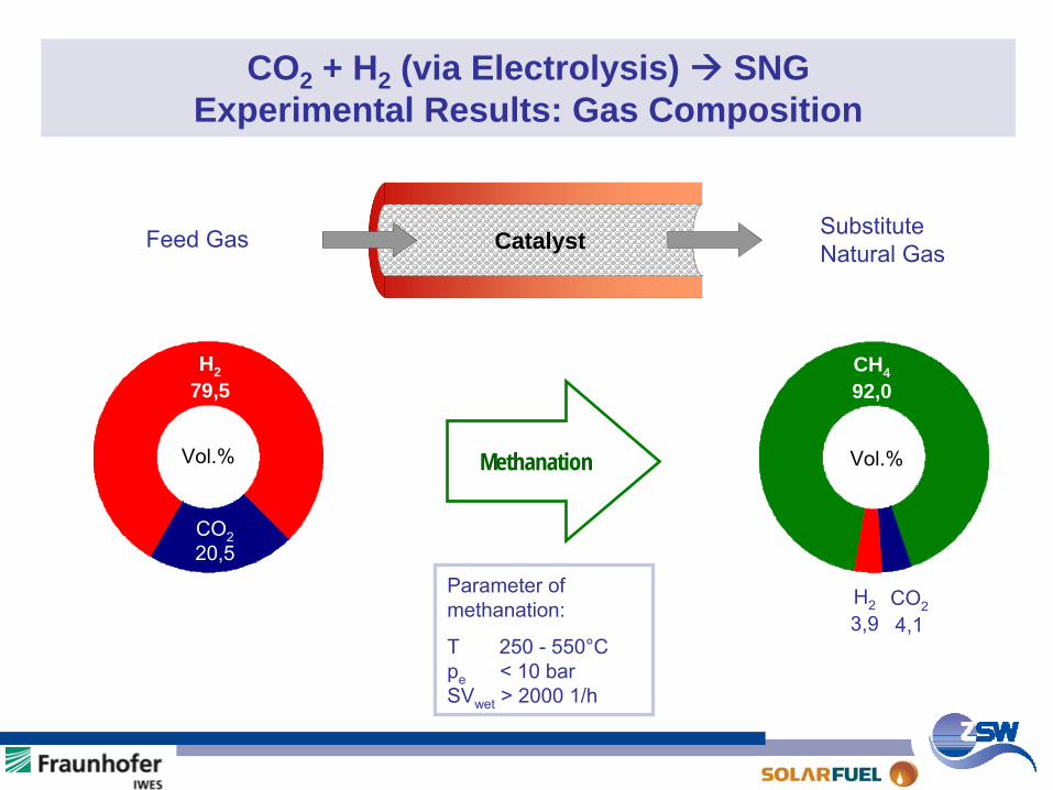
CO2 + H2 (via Electrolysis) SNGExperimental Results: Gas Composition
Parameter of methanation:
T 250 -
550°C
pe
< 10 bar
SVwet
> 2000 1/h
Catalyst Substitute
Natural Gas Feed
Gas
Vol.%
H2 79,5
CO2
20,5
Methanation
H2
3,9
CO2
4,1
CH4 92,0
Vol.%
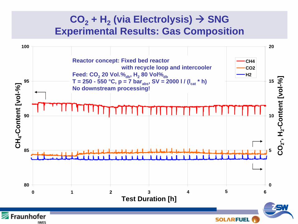
80
85
90
95
100
13400 17000 20600 24200 27800 31400 35000Test Duration [h]
CH
4-C
onte
nt [v
ol-%
]
0
5
10
15
20
CO
2-, H
2-C
onte
nt [v
ol-%
]
CH4CO2H2
0 1 2 3 4 5 6
CO2 + H2 (via Electrolysis) SNG Experimental Results: Gas Composition
Reactor concept: Fixed bed reactor with recycle loop and intercooler
Feed: CO2 20 Vol.%db , H2 80 Vol%dbT = 250 - 550 °C, p = 7 barabs , SV = 2000 l / (lcat * h)No downstream processing!
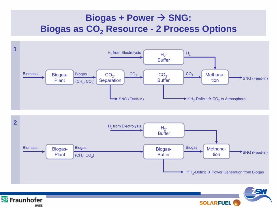
Biogas + Power SNG:Biogas as CO2 Resource - 2 Process Options
Biogas-
Plant
CO2
-
Separation
CO2
-
Buffer
Methana-
tion
H2
-
Buffer
H2
-
Buffer
Biogas-
Buffer
Methana-
tion
Biogas-
Plant
Biomass
Biomass
Biogas
Biogas
(CH4
, CO2
)
(CH4
, CO2
)
CO2 CO2
H2 from Electrolysis H2
SNG (Feed-in)
if H2
-Deficit CO2 to AtmosphereSNG (Feed-in)
H2 from Electrolysis
BiogasSNG (Feed-in)
if H2
-Deficit Power Generation from Biogas
1
2
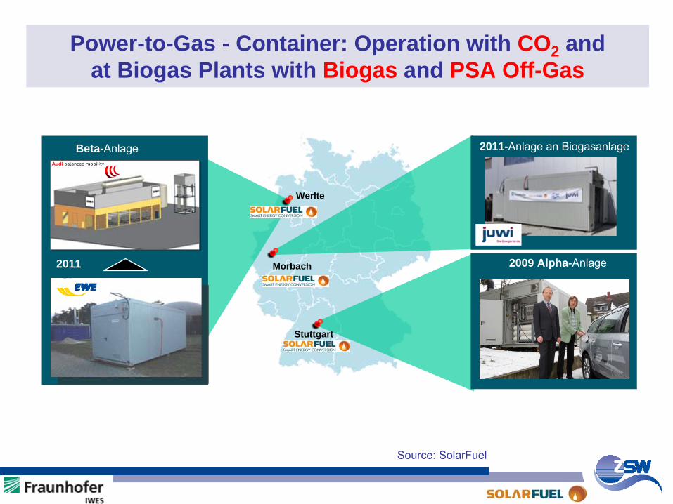
Power-to-Gas - Container: Operation with CO2 and at Biogas Plants with Biogas and PSA Off-Gas
Werlte
Stuttgart
2009 Alpha-Anlage
2011-Anlage an Biogasanlage
Morbach
Beta-Anlage
Source:
SolarFuel
2011
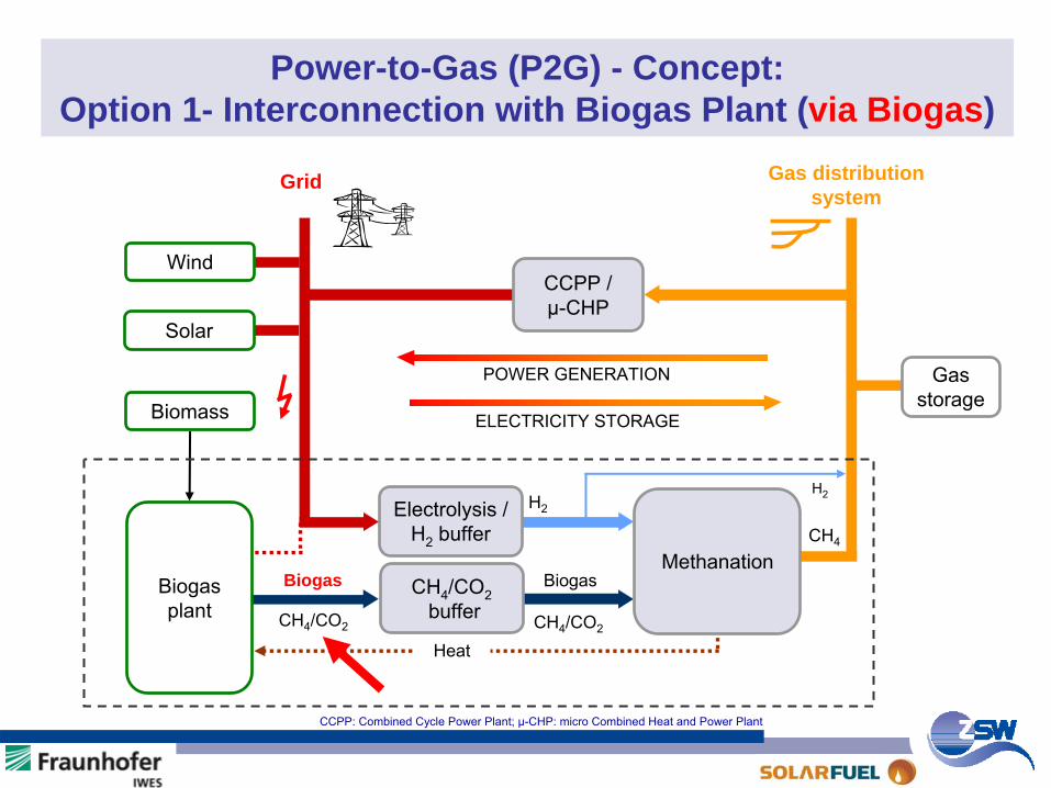
Power-to-Gas (P2G) - Concept: Option 1- Interconnection with Biogas Plant (via Biogas)
CCPP / µ-CHP
CH4
/CO2
buffer
Grid Gas distribution system
Electrolysis /
H2
bufferH2
Biogas
CH4
POWER GENERATION
ELECTRICITY STORAGE
Biogas
Gas
storageBiomass
Solar
Wind
H2
Biogas
plant
Methanation
HeatCH4
/CO2CH4
/CO2
CCPP: Combined Cycle Power Plant; µ-CHP: micro Combined Heat and Power Plant
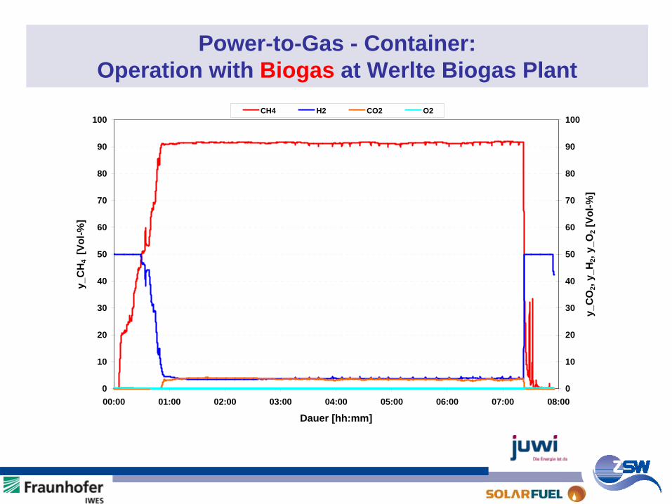
Power-to-Gas - Container: Operation with Biogas at Werlte Biogas Plant
0
10
20
30
40
50
60
70
80
90
100
00:00 01:00 02:00 03:00 04:00 05:00 06:00 07:00 08:00
Dauer [hh:mm]
y_C
H4
[Vol
-%]
0
10
20
30
40
50
60
70
80
90
100
y_C
O2,
y_H
2, y_
O2 [
Vol-%
]
CH4 H2 CO2 O2
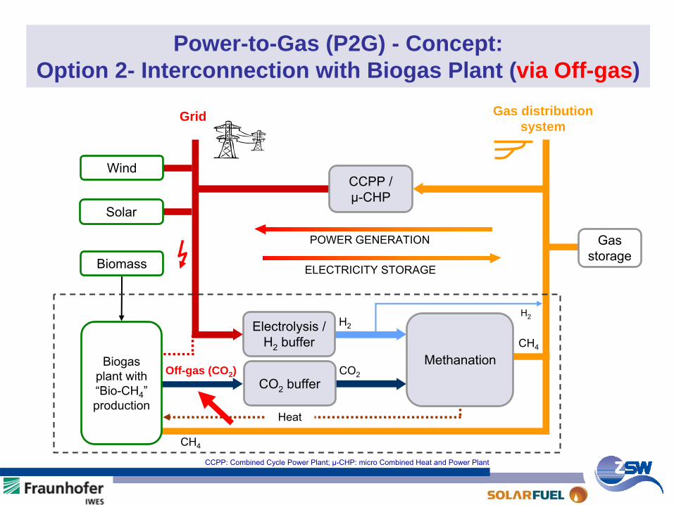
Power-to-Gas (P2G) - Concept: Option 2- Interconnection with Biogas Plant (via Off-gas)
CCPP / µ-CHP
CO2
buffer
Grid Gas distribution system
Electrolysis /
H2
bufferH2
CO2
CH4
POWER GENERATION
ELECTRICITY STORAGE
Off-gas (CO2 )
Gas
storageBiomass
Solar
Wind
H2
Biogas plant with “Bio-CH4
”
production
CH4
Methanation
Heat
CCPP: Combined Cycle Power Plant; µ-CHP: micro Combined Heat and Power Plant
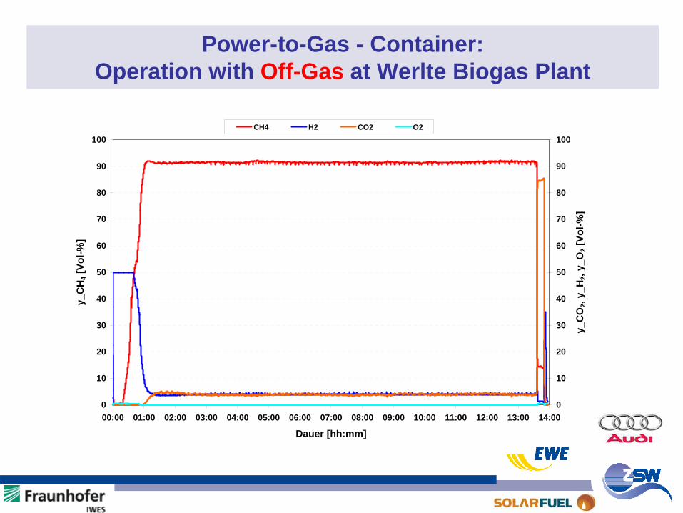
Power-to-Gas - Container: Operation with Off-Gas at Werlte Biogas Plant
0
10
20
30
40
50
60
70
80
90
100
00:00 01:00 02:00 03:00 04:00 05:00 06:00 07:00 08:00 09:00 10:00 11:00 12:00 13:00 14:00
Dauer [hh:mm]
y_C
H4 [
Vol-%
]
0
10
20
30
40
50
60
70
80
90
100
y_C
O2,
y_H
2, y_
O2 [
Vol-%
]
CH4 H2 CO2 O2
Award for Power-to-Gas - Concept: SolarFuel / ZSW / IWES
Award “ASUE” of the German Gas Industry in the field “Innovation and
Climate Protection”, 29.09.2010, Berlin
Agenda Part I: Power-to-Methanol / CO2 from Air Agenda Part II: Power-to-Gas (P2G)
Goal (P2G)SNG Production Routes from REP2G ConceptCO2 ResourcesConversion EfficiencyEnvironmental BenefitsResults from 25 kWe P2G Pilot PlantConclusions / Next Steps
SNG: Substitute
Natural
GasRE: Renewable
Energy
Goal (CO2 from Air)Concept 1996 (Batch Mode)Results 1996Concept 2009 (Continuous Mode)Results 2009Conclusions
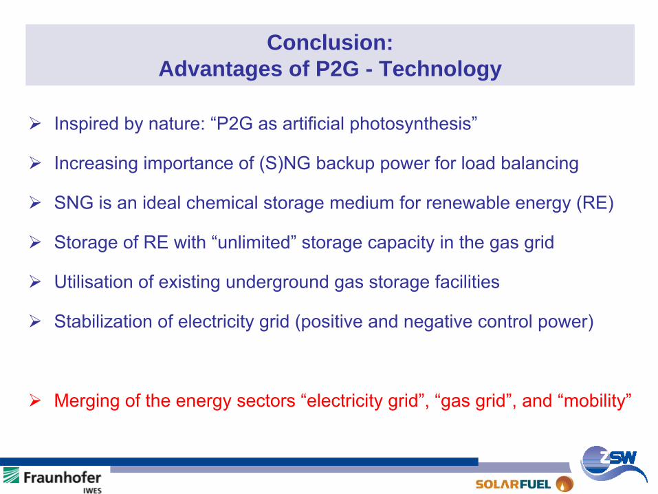
Conclusion: Advantages of P2G - Technology
Inspired by nature: “P2G as artificial photosynthesis”
Increasing importance of (S)NG backup power for load balancing
SNG is an ideal chemical storage medium for renewable energy (RE)
Storage of RE with “unlimited” storage capacity in the gas grid
Utilisation of existing underground gas storage facilities
Stabilization of electricity grid (positive and negative control power)
Merging of the energy sectors “electricity grid”, “gas grid”, and “mobility”
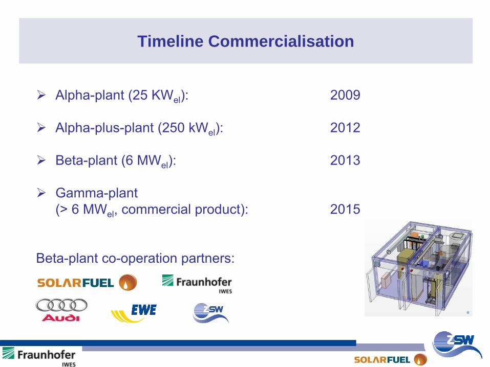
Timeline Commercialisation
Alpha-plant (25 KWel): 2009
Alpha-plus-plant (250 kWel): 2012
Beta-plant (6 MWel): 2013
Gamma-plant(> 6 MWel
, commercial product):
2015
Beta-plant co-operation partners:
Visit of the President from Turkey Abdullah Gül and Prime Minister Kretschmann at ZSW (21.09.2011)
An interesting discussion !
Thanks for your kind attention.