EXPERIMENTAL AND THEORETICAL STUDYOF THE- … Bound... · r 388 ,philips res. repts 15,7-29, 1960...
23
R 388 , Philips Res. Repts 15, 7-29, 1960 EXPERIMENTAL AND THEORETICAL STUDY OF THE- DOMAIN CONFIGURATION INTHIN LAYERS OF BaFe12019 by C. KOOY and U. ENZ 538.114: 538.245 Summary With the aid of the optical Faraday effect the domain configuration and. the magnetization process in thin transparent monocrystalline plates of BaFe12019 are studied. The plates have surfaces paraIIel to the basal plane of the hexagonal structure. The domain pattern consists of line- shaped domains. The domain width is measured as dependent on the applied magnetic field parallel to the c-axis. The width of a reversed domain decreases slowly with the applied field reaching a finite thickness near saturation, whereas the width of a domain magnetized in the direc- tion of the applied field increases rapidly near saturation. In this stage the remaining reversed line-shaped domains 'contract towards cylin- drical domains which coIIapse at slightly higher fields. Saturation is reached in a field well below 4,.[.. The demagnetizing energy of a partly magnetized thin uniaxial crystal having the easy axis normal to the surface is calculated for a domain pattern consisting of straight parallel domains. The stable domain configuration for a given value of the magnetic field is obtained by minimizing the total energy. The solu- tion is obtained in the form of two simultaneous equations containing the two different domain widths, which are evaluated by an electronic computer. Theoretical magnetization curves are deduced. The general accordance between experiment and theory is good. Résumé La distribution des domaines et le processus d'aimantation de minces plaques transparentes de BaFe12019 monocristallin sont étudiés à l'aide de l'effet optique de Faraday. Les faces des plaques sont parallèles au plan de base du réseau hexagonal, Les domaines sont linéaires, et l'on mesure leur largeur en fonction d'un champ magnétique appliqué parallèlement à I'axe c. La largeur d'un domaine inversé décroît lente- ment lorsque Ie champ appliqué augmente, et tend vers une valeur finie lorsqu'on s'approche de la saturation. Par contre, la largeur d'un do- maine aimanté dans Ie sens du champ appliqué croît rapidement au voisinage de la saturation. Dans cet état, les domaines linéaires inversés qui subsistent se contractent de manière à prendre une forme cylindrique, et ils disparaissent pour des champs légèrement plus élevés. La satu- ration est atteinte dans un champ bien inférieur à 4,.[ s- L'énergie de démagnétisation d'un mince cristal uniaxial partiellement aimanté et dont l'axe privilégié est normal à la surface est calculée dans Ie cas de domaines rectilignes parallèles. La configuration stable pour une valeur donnée du champ magnétique s'obtient en minimisant l'énergie totale. La solution est donnée par deux équations simultanes qui contierment les deux largeurs des domaines et qui furent résolues à l'aide d'une machine à calculer électronique. On en déduit les courbes d'aimantation théoriques. D'une manière générale, les résultats expérimentaux con- cordent bien avec la théorie. Zusammenfassung Mit Hilfe des optischen Faradayeffektes wird die Weissgebiet-Struktur und der Magnetisierungsproze13 in dünnen durchsichtigen mono-
Transcript of EXPERIMENTAL AND THEORETICAL STUDYOF THE- … Bound... · r 388 ,philips res. repts 15,7-29, 1960...

R 388 , Philips Res. Repts 15, 7-29, 1960
EXPERIMENTAL AND THEORETICAL STUDY OF THE-DOMAIN CONFIGURATION INTHIN LAYERS
OF BaFe12019
by C. KOOY and U. ENZ538.114: 538.245
Summary
With the aid of the optical Faraday effect the domain configuration and.the magnetization process in thin transparent monocrystalline platesof BaFe12019 are studied. The plates have surfaces paraIIel to the basalplane of the hexagonal structure. The domain pattern consists of line-shaped domains. The domain width is measured as dependent on theapplied magnetic field parallel to the c-axis. The width of a reverseddomain decreases slowlywith the applied field reaching a finite thicknessnear saturation, whereas the width of a domain magnetized in the direc-tion of the applied field increases rapidly near saturation. In this stagethe remaining reversed line-shaped domains 'contract towards cylin-drical domains which coIIapse at slightly higher fields. Saturation isreached in a field well below 4,.[.. The demagnetizing energy of apartly magnetized thin uniaxial crystal having the easy axis normal tothe surface is calculated for a domain pattern consisting of straightparallel domains. The stable domain configuration for a given value ofthe magnetic field is obtained by minimizing the total energy. The solu-tion is obtained in the form of two simultaneous equations containingthe two different domain widths, which are evaluated by an electroniccomputer. Theoretical magnetization curves are deduced. The generalaccordance between experiment and theory is good.
RésuméLa distribution des domaines et le processus d'aimantation de mincesplaques transparentes de BaFe12019 monocristallin sont étudiés àl'aide de l'effet optique de Faraday. Les faces des plaques sont parallèlesau plan de base du réseau hexagonal, Les domaines sont linéaires, etl'on mesure leur largeur en fonction d'un champ magnétique appliquéparallèlement à I'axe c. La largeur d'un domaine inversé décroît lente-ment lorsque Ie champ appliqué augmente, et tend vers une valeur finielorsqu'on s'approche de la saturation. Par contre, la largeur d'un do-maine aimanté dans Ie sens du champ appliqué croît rapidement auvoisinage de la saturation. Dans cet état, les domaines linéaires inversésqui subsistent se contractent de manière à prendre une forme cylindrique,et ils disparaissent pour des champs légèrement plus élevés. La satu-ration est atteinte dans un champ bien inférieur à 4,.[ s- L'énergie dedémagnétisation d'un mince cristal uniaxial partiellement aimanté etdont l'axe privilégié est normal à la surface est calculée dans Ie cas dedomaines rectilignes parallèles. La configuration stable pour une valeurdonnée du champ magnétique s'obtient en minimisant l'énergie totale.La solution est donnée par deux équations simultanes qui contiermentles deux largeurs des domaines et qui furent résolues à l'aide d'unemachine à calculer électronique. On en déduit les courbes d'aimantationthéoriques. D'une manière générale, les résultats expérimentaux con-cordent bien avec la théorie.
ZusammenfassungMit Hilfe des optischen Faradayeffektes wird die Weissgebiet-Strukturund der Magnetisierungsproze13 in dünnen durchsichtigen mono-

8 C. KOOY arid U. ENZ
kristallinen Plättchen aus BaFe12019 untersucht. Die planparalleienOberflächen der Plättchen sind identisch mit der Basisfläche der hexago-nalen Struktur. Die Breite der Weissgebiete wird gemessen als Funktiondes äuJ3eren Feldes, das parallel zur c-Achse liegt. Die Breite eines demFeld entgegengesetzten Weissgebietes nimmt mit zunehmendem Feldlangsam ab und erreicht einen endlichen Wert in der Nähe der Sätti-gung, während dort die Breite der Gebiete mit dem Magnetisierung-vektor in Feldrichtung sehr rasch zunimmt. Bei weiterer Erhöhung desFeldes ziehen sich die restierenden entgegengesetzten Weissgebiete zusolchen von zylindrischer Form zusammen, die ihrerseits bei einemleicht höheren Feld zusammenbrechen. Die Sättigung wird in einem Felderreicht, das wesentlich unter 4,,18 liegt. Die Demagnetisierungsenergieeines teilweise magnetisierten uniachsialen Kristalles mit der magneti-schen Vorzugsrichtung senkrecht zur Oberfläche wird berechnet füreine Domänenstruktur die aus geradlinigen paraUelen Weissgebietenbesteht. Die stabiIe Struktur der Weissgebiete in einem beliebigen Feldwird durch Differentiation der totalen Energie berechnet. Die Lösungwird erhalten in Form von zwei simultanen Gleichungen, die die stabilen~Breiten der Weissgebiete enthalten. Diese werden aufeinem elektroni-schen Rechengerät gelöst. Theoretische Magnetisierungskurven werdendaraus abgeleitet. Die allgemeine Übereinstirnmung zwischen Experi-ment und Theorie ist gut.
1. Introduetion
One of the most elegant methods of observing ferromagnetic domains is toutilize the Faraday effect, and look at the domains under the polarizingmicroscope, using transmitted light. Unfortunately the general applicabilityof this method is restricted because of the opacity of the majority of ferro-magnetic materials. However, the transparency of some oxidic ferromagneticsis sufficient to take advantage of the Faraday rotation, allowing observationof the domain structure of specimens with a thickness of the order of severalmicrons. One of these materials is the hexagonal compound BaFe12019 1),the main constituent of the permanent magnetic material Ferroxdure.
Large single crystals of BaFe12019 can be grown by slow cooling of a nearlyeutectic melt. These crystals have the shape of hexagonal plates which floaton the surface of the melt. Closer examination of the surface of these crystalsreveals that sometimes thin platelets peel off from the surface which was notin contapt with the melt during solidification. These monocrystalline plateletsare transparant to the red part of the visible range and have perfectly parallelsurfaces which by X-ray examination were found the be identical with the(0001) plane of the hexagonal structure. Typical dimensions of these plateletsare O·50 X O·50 X 0·002 mm. The reason for the occurrence of the platelets is notclear. The cleavage may be induced by thermal stresses during cooling or bystresses due to reduction and reoxidation of.the surface.. Some of the magnetic properties 2) of BaFe12019 are reproduced in fig. 1.The easy direction of magnetization is the hexagonal c-axis, the crystal aniso-tropy energy constant K; being 3.3.106 ergs/cm3 at room temperature. Theanisotropy field HA = 2K/Is is about 17000 Oe which exceeds by far the maxi-mum demagnetizing field 47T1s = 4700 Oe. Therefore, in thin platelets we ~ight

DOMAIN CONFIGURATION IN LAYERS OF BaFe12019 9
5K,
Ö -3(Ia erg cm ) 4
r '2
'"1'\ I o: I 100(gauss cm3 g-1;\K , r~
\I-I---
1\\ 60
'r..;-!7 ."t'", ~- H r-, ~ 40
A ),r-, '\~I"" \ 20
1
'\~
80 Fe12019I I
5
o100 200 300 400 500 600 700 800
____ T(OK) 99440
Fig. 1. Saturation magnetization u, crystal anisotropy Kl, and anistropy field HA ofBaFel2010
expect a domain structure like that shown in fig. 2 in which the magnetizationas well as the 1800 domain walls are perpendicular to the plane of the plate,and closure domains do not occur. Such a domain structure is very well suitedfor observation with the polarizing microscope, using transmitted light.
Incident lightlin.polarized
Transrniited Ught j j j99441
Fig. 2. Schematical domain structure in thin plates of BaFe12019.
2. Experimental
In order to observe the domain structure during magnetization a specialmicroscope arrangement was constructed in an electromagnet. This wasachieved by mounting an objective and an eye piece into a central bore in one

10 c. KOOY and U. ENZ
of the poles and illuminating the samples, by an optical condenser systemthrough the other pole as shown in fig. 3. The magnification used is about1800 X and micrographs of the observed patterns can be obtained with goodresolution and contrast. The periods of the domain structure were measured'by comparison with a calibration plate photographed in the same optical
1~~l:I=iS~:=lrllt~~Wv~~I'~!~tI==-=~;iI3
99442
Fig. 3. Magnet with optical arrangement for the observation of the domain configurationin the presence of a magnetic field. 1: compact light source, 2: lens, 3:diaphragm, 4: poles withcentral bore, 5: polaroid, 6:objective, 7: sample holder for centring and focussing, 8: eye piece.
arrangement. The magnetic field which was at maximum 5000 Oe proved to behomogeneous in the region occupied by the sample. The field was measured bymeans of a Hall probe and independently by means of a ballistic method.The results of both methods agreed within 1%. The thickness of the plateletswas measured both optically and by means of an electronic displacement meterwhich allows measurement of displacements of 0·1 micron.
3. Observations
3.1. Magnetization processIt appears that the domain pattern in the demagnetized state depends
strongly upon the way of demagnetizing. If this occurs by saturating the plateletsin a strong magnetic field and subsequently reducing this field to zero, a patternof essentially straight line domains is obtained as shown in fig. 4, in which theblack and white stripes correspond to Weiss domains of opposite polarity.
i, Due to the strong demagnetization the remanence is negligible. If, on the otherhand, the magnetic field does not produce complete saturation a labyrinthstructure is'obtained as shown in fig. 5. A similar pattern is observed when thecrystal is cooled down through the Curie point in zero applied field.

DOMAIN CONFIGURATION IN LAYERS OF BaFe12019 11
Fig. 4. Domain pattern of a thin plate of BaFe12019at zero applied field after saturation in ahigh field. Thickness of the plate D = 3.10-4 cm.
rIn fig. 6 the domain structures during the magnetization process are shown
starting from the demagnetized state with the labyrinth type structure and infig. 7 the same structures are shown but now starting from the demagnetizedstate with the essentially ~raight line domain pattern.
Fig. 5. Domain pattern of the same plate as in fig. 4' at zero applied field after cooling downfrom the Curie point.
On the application of a field the width dl of the domains with their magneti-zation vector parallel to the applied field increases, and the width d2 ofthe revers-ed domains decreases. In low fields this occurs in such a way that dl + d2,further referred to as the period of the pattern, remains approximately constant

12 c. KOOY and U. ENZ
a
f
d
b e
c
Fig. 6. Domain structures at different values of the applied field H during magnetization,starting from the pattern as shown in fig. 4. The applied field is parallel to the c-axis.
(a) H = 0 Oe(b) H = 1690 Oe(c) H = 2070 Oe
(d) H = 2620 OeCe) H = 2820 Oe(f) H = 3190 Oe
DOMAIN CONFIGURATION IN LAYERS OF BaFe12019
a
b
c
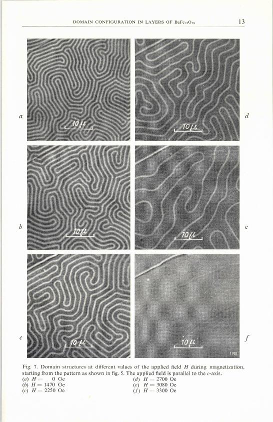
Fig. 7. Domain structures at different values of the applied field H during magnetization,starting from the pattern as shown in fig. 5. The applied field is parallel to the c-axis.(a) H = 0 Oe (d) H = 2700 Oe(b) H = 1470 Oe (e) H = 3080 Oe(c) H = 2250 Oe (1) H = 3300 Oe
13
d
e
f

14 C. KOOY and U. ENZ
and the pattern remains essentially the same. When approaching saturation,however, the width dl increases very rapidly with increasing field, whereas thewidth d2 decreases only slightly. The main changes in the total domain patterntake place in this stage of the magnetization process. Reversed domains do not:finally disappear by reducing their widths to zero,. but by diminishing theirlengths. . ,
In fig. 8 the period of the pattern averaged over 20 domains is plotted againstthe applied field for some 30 values of the field. The experimental points for thelabyrinth-type structure and the straight-line domain structure coincide. Dueto' the high magnifications used an accurate measurement of dl and d2 separa-tely turned out to be impossible. Yet the measurement of the period yieldedsufficient information for checking the theory.
[1ötm]12
6
d'~/2I
JJ
V..o-e-""
,.,...".-
.
11
la
9
8
7
5
3
2
2000 3000~H [Oe] 99443
Fig. 8. Experimentally observed period dl + de of the domain pattern in a plate of BaFel2019ofthickness D = (3'0 ± 0'1).10-4 cm, as a function ofthe applied field H.
1000
The increase in period of the labyrinth structure takes place by the domainsdiminishing in length, causing them to unwind or .straighten. In the straight-line domain pattern peculiarities in the structure can be observed bearing astrong resemblance to edge dislocations in a crystal lattice. The increase inperiod of the pattern takes place by a climb process of these edge-dislocation-like structures.

DOMAIN CONFIGURATION IN LAYERS OF BaFe12019
A remarkable thing is that saturation is reached with an applied field consi-derably smaller than 47TIs, so that the internal field in the saturated state canapparently be opposite to the magnetization.
3.2. Effects near saturation
When the crystal approaches saturation the distance between two reverseddomains becomes very large and often single reversed domains can be observedwhich apparently are stable on their own. The disappearance of such a reverseddomain takes place in an interesting way. Upon further increase of the appliedfield this domain contracts towards a cylindrical domain with a circular domainwall, the diameter of this cylindrical domain being of the same order as thewidth of the original line-shaped domain (fig. 9). This contraction of the line-shaped domains takes place within a small range of fields in which they appa-rently become unstable. Upon increasing the applied field the diameter of thesecylindrical domains decreases slightly until another critical field is reached atwhich they suddenly collapse and disappear. The platelet is then completely
Fig. 9. Stable reversed cylindrical domains, at H = 3500 Oe.
magnetized and all domain walls have been eliminated. On the basis of magneto-static consideration we will show that a single reversed line-shaped domain aswell as a single reversed cylindrical domain can be stable and that the criticalfield HKc for cylinders is higher than the critical field HKI for single line.
3.3. Wall nucleation and hysteresis
The dependence of the domain period on applied field, as shown in fig. 8,appears to be the same in increasing and decreasing fields. This reversibility,however, is lost if the field has been raised above the critical value HKc for the
15

16 C. KOOY and U. ENZ
'I i:k~
/./
/'/
//
/-:
99444
Fig. 10. Schematical representation of the hysteresis loop of a thin plate of BaFe12019. Line-shaped patterns between H = 0 and HI{l, reversed cylindrical domains for Hgl < H < H gC, nodomain walls in fields higher than Hgc. For fields decreasing from above Hu", single-domainbehaviour is maintained down to the nucleation fields HN', HN ", at which a starlike domainpattern appears suddenly. The different nucleation fields are correlated with different nuclea-tion points in the plate. The shape of the magnetization curves is inferred from fig. 14.
collapse of the cylindrical domains. After the elimination of these cylindricaldomains hysteresis occurs and the specimen remains saturated upon decreasingthe applied field, until at a certain value HN a domain pattern suddenly appears.This pattern suddenly establishes the equilibrium magnetization with a periodof the domain structure given by the corresponding value on the reversiblecurve of fig. 8. In this way cycles can be made as indicated schematically infig. 10.
a b
Fig. 11. Starlike domain pattern nucleated at HN = 2000 Oe. (a) Micrograph taken at zeroapplied field. (b) Micrograph taken at H = 2400 Oe.

DOMAIN CONFIGURATION IN LAYERS OF JlaFe12019 17
Those suddenly appearing domain structures have the remarkable featurethat the domains seem. to emerge radially from a central point as shown infig. 11.This suggests that the first reversed domain in the saturated plate nuclea-ted at this centre and spreads out through the entire specimen by a splittingprocess. This splitting of the outgrowing reversed domains gives rise to the edge-dislocation-Iike structures and enables the domain structure to have a constantperiod in a star pattern. In this way the domain structure. shown in fig. 4, takenat a long distance from the nucleation centre, came into existence.In a single experiment only one nucleation centre can be observed in the
entire platelet. Repeated nucleation experiments by performing the cycle des-cribed above show that a specimen possesses a number of these nucleationcentres, each one having its own more or less constant, characteristic value ofthe applied field at which nucleation occurs. These centres always appear to belocated at the same spots in the platelet.
The fact that more than one nucleation centre can be observed means that acertain centre is not always active so that if, for instance, nucleation centre Idoes not give nucleation at HN1 in the decreasing field, nucleation centre IIcan become operative and start nucleation at HNII. Usually the investigatedspecimens appear to have 2 to 4 of such nucleation centres with nucleation fieldsranging from 500 to 2000 Oe. Which one of the possible centres is chosen in aparticular cycle cannot be predicted; however, nucleation occurs more fre-quently at those centres which have the highest nucleation fields.Nothing is known about the nature of these nucleation centres. One might
assume that it consists of some imperfection in the crystallattice which is ableto lower the value, H = -2KIIs + 47TIs= - 12000 Oe, of the external fieldwhich is theoretically required to produce a reversal of magnetization.
4. Qualitative theoretical considerations
In order to understand the observed magnetization process in terms ofdomain behaviour we must explain(a) that saturation is reached in a field considerably smaller than 47TIs, nor-mally expected for plates under these conditions,(b) that reversed straight-line domains seem to have a stable finite width upto saturation.
Let us consider the simplified situation near saturation of an infinite plate of .thickness D with a single reversed straight-line domain of width d.The expression giving the difference in energy [cu: of this situation as a
function of dcompared to the completely magnetized state consists of'threeterms.(i) A constant term of the Bloch wall energy 2uwD.(U) A term 2HIsDd due to the magnetization reversal in the domain against
the applied field.(iii) A negative magnetostatic term giving the change in energy by the reversal

18 c. KOOY and U. ENZ
of the magnetization in the domain in the demagnetizing field originatingfrom the free poles of the rest of the plate. If d 4::.D this demagnetizing fieldwill be 47TIsand penetrate completely the reversed domain. The magneto-static energy term will then be -87TIs2Dd .
. On increasing the width of the reversed domain, however, the demagnetizingfield will become less than 47T1s and if d ~ D this magnetostatic term willbecome nearly independent of d. According to these general considerations themagnetostatic energy as a function of d can be represented graphically as shownin fig. 12.
Fig. 12. Difference in energy LlE of a plate with a single reversed straight-line domain ofwidth d, compared with the completely magnetized state, as a functionof d.
For this straight-line domain !lE shows a minimum if H < 47T1sat a certainvalue of d which will be the energetically favourable width of the reverseddomain. This domain will only be stable if for this minimum!lE < 0, and itmust vanish at an applied field for which !lE > o. Because the initial slope of theE vs d curve is given by -2(47TIs-H)D this critical field is smaller than 47T1s.Because !lE has a minimum for a finite value of d, the domain, when it hasbecome unstable, cannot-disappear simply by reducing d to zero because then
,(jE
1
\\
\ 81(IIDd f(~)\\\\\\\
99445

DOMAIN CONFIGURATION IN LAYERS OF BaFe12019--------------------~--19it has to surpass an energy barrier. This does not have to occur if, instead, thelength of the domain decreases and the line-shaped domain' can contracttowards a cylindrical domain, as in fact has been observed. Analysis shows thatthese cylindrical domains are more stable due to a more complete penetrationof the demagnetizing fields. The cylindrical domains therefore collapse at aslightly higher field.
5. Calculation of the domain widths in partly magnetized plates
We consider a monocrystalline ferroriJ.agnetic plate under the followingassumptions:(1) The material is uniaxial with the preferential direction of the magnetizationnormal. to the surface of the plate.(2) The plate has the uniform thickness D and its lateral dimensions are in-finite.(3) The anisotropy field HA = 2K/ls is large compared with 47Tls, so thatclosure domains do not exist. However, we will take into account that under theinfluence of the demagnetizing field the direction of the magnetization maydepart slightly from the c-axis (,u-effect).(4) The external magnetic fieldH is applied parallel to the preferential direction.(5) The thickness of the plate is assumed to be small enough so that the domainstructure can be considered to consist of straight domains with the demagneti-zation as well as the 1800 Bloch walls perpendicular to the surface.
The total energy of the plate is the sum of three parts: wall energy, the energyof the magnetization in the external field and the demagnetizing energy of thedomain configuration.
Ix
z
o
99446
Fig. 13. Schematical domain structure of a partly magnetized thin plate of BaFe12019.
The situation is shown in fig. 13. The wall energy Ew per cm2 of the plate is
(1)
where Uw is the specific wall energy and dl and ds. are the widths of the domainsparallel and antiparallel to the direction of the applied field H, respectively.The energy EH per c,m2 of the plate in the applied field H is given by
EH = -H lsD (dl-d2)/(dl + d2) = -H lsD I/Is, (2)

20 C. KOOY"and U. ENZ
where Is is the saturation magnetization at the material and I the resultantmagnetization of the sample.
In appendix 1 we show that the demagnetizing energy per cm2 of thedomain configuration of fig. 13, including the ,u-effect for small ,u's [,u = 1 +2711s2/Kj, is given by
ED = 271Is2D (;IJ + (3)
-00
+ 16Is; Dy fL \' ~ sin2 [n71(1 +~)] sinh n71a. ,712 a. fi n3 2 Is. sinh n71a+ i fL cosh nno.
where we use the abreviations
I/Is = (dl-d2)/(dl + d2) and a = Dip./(dl + d2). (4)
We may interpret expression (3) as follows. The first part of this expressionrepresents the demagnetizing energy of a homogenously magnetized plate withmagnetization 1. The second part is a correction for the deviation from homo-geneity due to the domain structure. For the assumed type of domain structurethis expression is valid for arbitrary thickness D. For not too small values of awe may replace (iP:-I) cosh(n71a) by (y;-I) t exp (n71a). This l is justifiedfor our observed values of a. In this way (3) reduces to .
E_D = 271Is2D (fr +,- 00 .
+ _~yfL _ ~ Is2 D \' ~ sin2 [n71(1+ ~)] [1- exp (- 271na)]. (5)1 + ifL 712 a i...J n3 2 Is
11=1
For the special case H= 0 and 1=0 [dl = d2= d] we deduce from eq. (5) that
2 16 IOO
1 [ ( DY;)]E = - d 1- ex - 71k --D 1+ Y fL 712 (2k + 1)3 P \ d'
k=1
(6)
This special case [for ,u = 1] was found independently by Malek and Kam-bersky 3). For the special case D» d we obtain from (6)
ED = 3·42 Is2dj(1 + i;). (7)
For the case of fL= 1 this reduces to the expression already given by Kittel.")
ED = 1·71 Is2 d, (8)
which is derived by neglecting the mutual interaction of the poles on bothsurfaces of the plate. .
The stable-domain widths dl and d2 in an arbitrary stage of magnetization

DOMAIN CONFIGURATION IN LAYERS OF BaFe12019 21
can be found by equating the derivatives bE/beI/Is) and bE/ba of the totalenergy E = Ew + EH + ED to zero, giving the simultaneous equations
47TI-H 2{p, 1 LOO 1 (I) .+ ',1 - - sin 7Tn 1+- [1- exp (-27Tna)] = 0, (9)4~ l+y~7T~ ~ L
n=l
00
__1 \' _!_ sin2 [n7T(1+ ~)][1- (1+ 27Tna) exp (-27Tna)]-47T2a2 Z: n3 2 Is
n=lUw 1+ yP,
---:= -~ - 0 (10)(418)2 Dy ~ 2y ~ - .
These are two equations determining a and I and thus dl and d2 for any givenvalue of the applied field. The two equations have been evaluated numericallyfor the case of ft = 1 on the Philips electronic computer by Duijvestijn andBoonstra 5) of this laboratory. In fig. lof this work the period of the domainstructure expressed in the reduced quantity /)1 + /)2 = {(418)2/uw} ( dl + d2)is given as a function of the reduced plate thickness T = P (418)2/ Uw for severalvalues of the parameter I/Is. In this figure is shown that for all stages of themagnetization process there exists an absolute minimum of the period of the -domain structure as a function of the plate thickness, the minimum occurringfor a plate thickness of the order of T = 5. For values of T < 5 the period in-
0.2
I / 1/r;}s /~=75 }1/r=/OO/
IJ 1/ V 1/ =00
11 /VJJ 1/ /V/ / /V
1/ V/ VIt /W
f=[4Isf utV
If/
I/Is
t 0.8
0.6
oo 0.2 0.4 0.6 0.8-H/4.1f1s
7.0
99447
Fig. 14. Theoretical magnetization curves of an infinite plate with the preferential direction ofthe magnetization perpendicular to the plane of the plate for some parameter values of thereduced thickness or= (41.)2 D/uw.

22 C. KOOY and U. ENZ
creases again with decreasing plate thickness. This reflects a tendency of theplate to become single domain. However, it can be shown that infinite platesget single domain only for vanishing values of the thickness.
In their fig. 2 Duijvestijn and Boonstra give the relation between the periodof the domain structure in terms of (dl + d2)/D and the applied field H/4nls,again for the same parameter values of I/Is.
From these numerical data all the required information can be found. Inparticular the magnetization curves of the plate can be determined. In fig. 14calculated magnetization curves are given for some values of T. The magneti-zation curves are not straight lines in general, as would be expected from classi-cal continuum theory but show characteristic deviations. Saturation occurs in a
300
3
i-T'=[4Isf #w~2=[4Is]2~
7'=100
1//1
VJd,+02 V V li;- ./
V i>-Ol-< !--t-- 02 -
0 -0
2804,ó2
1 250
240
220
200
180
150
140
120
100
80
50
2
o ill ~ ~ ~ ~ M ~ M M W-Hj411'Is 99448
Fig. 15, Theoretical domain width Ih and 1)2 as a function of the applied magnetic field for thespecial case T = 100.
field smaller than 41TIs, which is in agreement with the qualitative considerationsof sec. 4. The saturating field gets smaller with decreasing plate thickness. In

DOMAIN CONFIGURATION IN LAYERS OF BaFe12019
:fig.15 the calculatedreduced domain widths Oland 02 with 01,2= (41s)2dl'2/Uwis shown for T = 100 as a function of the applied :field, expressed inH/47T/s. The width 02 of the reversed domains decreases only slowly uponmagnetization whereas the width Olof the domains with magnetization parallelto the applied :fieldincreases very rapidly near saturation. The period 01+02is approximately constant in low :fieldsand changes rapidly near saturation,which is in general accordance with the observations.In :fig.16 the theoretical curve and the experimental points of dl +d2 are given
as a function of the applied :field for the measured plate thickness of D =3.0.10-4 cm. The theoretical curve is obtained with the parameter valuesuw* = 2·8 erg cm-2 and Is = 345 gausses, chosen to :fitthe experimental curve.
1 iIII
__ a. -- ITheoreticalD = 3·0.1O-4-cmIs = 345 gauss TOW~2·8 erg crr(JN=0·95.47t
!I
I if ITheeretical ~ Ht LIcrl/l al fie
V I~ V I1
I
9
8
7
6
5
3
2
2000 3000
-H[De]40001000
_ 99449
Fig. 16. Theoretical curve and experimental points of the period dl + dz as dependent onthe applied field.
The theoretical calculations are valid only for infinite plates, whereas themeasurements were carried out on a :finiteplate with a demagnetizing factorN = 0·95.47T. This is taken into account by reducing the :field scale for thetheoretical curve by 5%. The saturation magnetization Is = 345 gausses is thebulk value of BaFe120l9 for 50°C. The temperature of the specimen is raisedto about this value during the observation ofthe domain structure by the intenseillumination of the plate.
23

24 C. KOOY and U. ENZ
Although the eqs (9) and (10) have been evaluated for # = 1 the Weffect can still be taken into account by considering the chosen value of uw*as an effective value of the wall energy from which the specific wall energy Uw
can be obtained by the relation
(11)
With the value ofthe rotational permeability # = 1·2 for BaFe12019 we obtainthe specific wall energy Uw = 2·7 erg cm-2 at 50 oe. The general agreement ofthe calculations with the experiment can be considered to be good.
6. Stability near saturation of a single reversed domain of straight line andcylindrical shape
The critical field at which a single reversed straight-line domain becomesunstable and has to disappear, as discussed in sect. 4, can be calculated from(9) and (10). For values of I close to Is the summations over n may be replacedby the corresponding integrals. When the limits for a-+ 0 of the well-knownsolutions of these integrals are taken in the case of f1- = 1, the two simultane-ous equations
Uw 8-- = - = fJ2 In (1 + fJ-2) + In (1 + fJ2)2Is2D T
(12)
and[1- HKZ/47TIs] = (1/7T) [2 arctan fJ + fJ In (1 + fJ-2)] (13)
are obtained, in which fJ = d2/D. These equations determine the final stablewidth d2 of the reversed domain and the critical field H KZ above which the line-shaped domain becomes unstable. Using the value for Uw and Is determinedin the previous section we obtain numerically
d2 = 0,24.10-4 cm and HKz/47TIs = 0·819.
If we apply again the correction for the finite lateral dimensions of the platewith N = 0·95.47T we get H KZ= 3380 Oe, which is in agreement with the obser-vations as indicated in fig. 16.
As will be shown in appendix 2 the demagnetizing energy of a single reversedcylindrical domain of radius R in an infinite plate of thickness D is
(14)
The difference in energy of the single reversed cylindrical domain comparedwith the homogeneously magnetized state can thus be expressed by
~E = 27Tl!wRD - 2(47T1s-H) Is7TR2D + 1287TIs2R3/3 (1+ yp.). (15)
The cylindrical domain will become energetically unstable for /:iE > O. For
- _"--_ ..
DOMAIN CONFIGURATION IN LAYERS OF BaFe12019
f).E = 0 and small positive -values of !:iE, however, the domain can not dis-appear because it still has to surpass an energy barrier in order to reduce itsradius to zero. This barrier disappears at a value of the critical field at which()2 !:iE/()R2 = o. Thus the critical field H KC at which the cylindrical domainwill collapse can be found by the conditions ()!:iE/()R = ()2f).E/()R2 = 0,which gives the relation
47Tls - HKc = 8 -Vaw/D (1 + ift) . (16)
Using the values for aw and Is, dëtermined in sec. 5, and applying again thecorrection for the finite plate with N = 0·95.47T,we obtain H KC = 3630 Oe. Thisis in good agreement with the observed critical field HKc = 3820 Oe at which,after subsequent decreasing of the field, opening of the hysteresis loop occurs,indicating that all the cylindrical domains are collapsed.For the critical radius of a cylindrical domain we find from the same con-
dition
Rc = (l/8Is) -VawD (1 + -v ft) ,
which for our case gives Rc = 0.15.10-4 cm, which is also in agreement withthe observation.
Acknowledgement
The authors wish to thank Dr J. Smit for his stimulating interest in thiswork, the valuable discussions and for carefully reading the manuscript,Mr H. de Lang for the optical measurement of the thickness of the plate andadvice for the construction of the optical arrangement, Mr J. van der Walfor valuable assistance in making the micrographs.
Eindhoven, September 1959
REFERENCES
1) c. Ko oy, Philips tech. Rev. 19, 286-289, 1957/58.2) U. Enz, J. F. Fast and H. P. J. Wijn, Colloque international de magnétisme, Grenoble,
1958, 296-309. (Presented by H. B. G. Casimir.)3) Z. Má lek and V. Ka mb er sk y, Czech. J. Phys. 21, 416-421, 1958.4) C. Kittel, Rev. mod. Phys. 21, 541-583, 1949.5) A. J. W. Duijvestijn and B. P. Boonstra, Philips Res. Repts, 1960. (To appear.)6) J. B. Goo denough, Phys. Rev. 95, 917-932, 1954.
Appendix 1
To find the rnagnetostatic energy of the domain configuration of fig. 13weintroduce potentials (Vt, Ve) for the magnetic field, which take the followingform inside and outside of the plate:
25
(17)

26 C. KOOY and U. ENZ
I n7Tdl 27Tnx (27TnZ )Ve = ao+ an sin . cos exp .
dl+ d2 dl + de dl + d2
This approach is similar to that of Goodenough 6). The field inside of theplate is given by
Hl =- grad Vi .
The ,u-term occurs only in the potential Vi. The potential Vi fulfils the two-dimensional Laplace equation
(18)
where po is the magnetic charge density on the surface of the plate. The volumecharges are incorporated in the ,u-term on the left-hand side of the equation.This is possible as long as we have 1z R:! XZ Hz and I'l- R:! Is. Since the twopotentials are equal at the surface we obtain
ao = !boD and (7TnD) (7Tnz{;)an exp - = bn sinh d'
dl + d2 dl+ 2
From the condition that on the surface (z = tD) a discontinuity of the z-component of the field occurs we conclude
<> Ve/<>z- <> Vt./<>z= - 47TpO.
For the charge density po on the surface we introduce, according to the geo-metry of the problem,
(19)
representing a square wave.With the aid of the last two equations, we find
dl-d2bo = 47TIs ,
dl+ dz
8 1 [' 7TnD{p, - 7TnD{p,]bn = - Is (dl+ d2) - sinh + y f.L cosh t •
7T ~ ~+~ ~+~The demagnetizing energy per cm2 of the plate becomes
+!(d,+d,) +!D B
ED = - 47T(d~+d2) f I I HSBdxdz.-~(d,+d,) -l;D 0

DOMAIN CONFIGURATION IN LAYERS OF BaFe12019 27
Taking into accoun~ that Be = fl-Hx and 8Bz I":::i 8Hz this integral can be trans-formed into
which by introducing jhe potential Vi may be partially integrated to
By substituting (18) this reduces to+!<dád,)f po Vi dx. (20)
In this integrand only the surface pole density po given by (19) appears and notthe total pole density with e.g. the poles in the bulk created by the ,u-etrect.
Evaluating this integral (20) we obtain the demagnetizing energy given byeq. (3).
Appendix 2
We consider the situation of a single reversed cylindrical domain of radius Rin an infinite plate of thickness D (fig. 17). The difference in energy due to thereversal of the magnetization in this cylinder in the demagnetizing field Ho,
c:
D [sj 1 _I[s t
j + I, ,
r
, .: I :
l]i 99450
Fig. 17. Cylindrical reversed domain. R = radius of the domain; D = thickness of the plate;r, z are cylindrical coordinates.

28 C. KOOY and U. ENZ
originating from the poles of the surfaces outside the cylinder, isR +D/2
ÁED = -2 f f Hols 27T1' dl' dz·.o -D/2
For the field Ho we can write
in which Hi is the internal field in the cylinder originating from the poles on thecylinder surfaces. The integral .
R +D/2
- 2f f Hi Is 27T1' dl' dzo -D/2
can be transformed in a similar way as in appendix 1 into the surfaceintegral
R
- 2 f po (I') Vi (r,D) 27T ~.dl' .
oWe introduce potentials outside (Ve) and inside (Vi) the plate:
(21)
co
Ve = f J(k) Jo(kr) exp (-kz) dk,
oco •
Vi = fg(k) Jo (kr) sinh (i; kz) dk.
oFrom the identity of the potentials on the surface we obtain
J(k) exp (-kD 12) = gek) sinh (k{p,D 12) .
On the surface we demand further
b Velbz - bVilbz = 47TpO.
We represent the poles on the surface byco co
po (r) =f k dk ft Jo(kt) JoVa) ;oU) dz .
o 0Owing to the fact that the poles are Is inside a radius R and zero outside we get
R
Isft Jo(kt) dt = - (Is Rik) h(kR).
o

DOMAIN CONFIGURATION IN LAYERS OF BaFel2019 29
,\
From this we obtain the function gek) :
gek) [sinh (D{;;'/2) + l; cosh (D{;;'/2~] = - (Rik) h(kR) .
With the aid of this expression we are able to calculate integral (21) with theresult
co
r (R)2 sinh (kDl/-;;/2)87T2182 _ h2 (kR) r r: •
. k sinh (kDV ft12)+ Y ft cosh (kDy p.12)o
In the approximation of large thickness D, where we neglect all termse/(p (-kD) compared to 1, the integral can be evaluated, with the result
128 7T182 R33(1+Yp.) •
Thus for the difference in energy we find eq. (14).