
Practical hints for using numerical methods in rock mechanics

Experimental and Numerical Study of Rock breakage by
Pulsed Water Jets
Sevda Dehkhoda
SUMMARY of a thesis submitted for the degree of Doctor of Philosophy at
The University of Queensland in December 2011
Cooperative Research Centre for Mining (CRCMining)
Nominated for ISRM Rocha Medal 2014
Thesis Summary - S Dehkhoda
2
Abstract
Rock breakage is, arguably, the most important step in the mining process. Poor blasting practice
produces large boulders that are difficult and expensive to handle. The presence of oversized
boulders in draw-points can stop production in underground caving mines. Blasting and heavy
impact hammers are the main techniques used in mines to fracture oversized rocks, but both impose
undesirable extra costs as a secondary rock-breakage operation. Blasting is time-consuming and can
damage the infrastructure, whilst impact hammers are cumbersome and cannot be used where
boulders are not readily accessible. It is important, therefore, to develop more effective secondary
rock-breakage techniques.
Preliminary research demonstrated that pulsed water jets are routinely able to break large
(approximately 1m3) boulders of competent hard rocks in less than a minute. Therefore, they can
potentially be a more effective method for secondary rock-breakage. They can deliver high power
intensity with a low reaction force meaning that a lightweight, flexible apparatus can be employed.
The breakage mechanism of rocks under the impact of water pulses is, however, not yet clear.
A pulsed water jet consists of a series of discrete, large water drops travelling at high velocity.
These apply cyclical impact forces of short duration onto the target material. The water impacts
generate stress waves inside the rock samples and these waves can, potentially, influence the rock-
breakage process. The contribution of the stagnation water pressure on the target after impact may
also play a crucial role in fracture initiation and propagation in the rock. The geometrical properties
of the jet are controlled and influenced by the method that is used to generate the water pulses. The
original contribution of this research is the determination of the processes of water pulse formation
and the discovery of key factors that influence rock fracture initiation and propagation.
A straightforward method was employed to generate a single water pulse using a hammer that
stroke a piston, rested on top of a water-filled chamber. This impacting action pressurised the water,
causing it to be expelled at high velocity through a nozzle that was mounted on the chamber axis
opposite the piston. A theoretical investigation was undertaken to improve the understanding of this
system for generating water pulses. A computational model, on the basis of continuity and
momentum equations for a compressible viscous flow, was developed to simulate the pressure
dynamics in the chamber. This model was used to optimise the relative sizes of the hammer, the
piston, and the height of the water column in order to produce the largest and the highest-velocity
water pulses. The model was validated experimentally using a purpose-built apparatus.
Thesis Summary - S Dehkhoda
3
Research was conducted to measure the impact loading of the water pulses on a target material. The
main challenge was to measure this load for an event that lasted for less than one microsecond. This
obviously required an extremely fast-response sensing system to capture the induced stress wave
from the water hammer pressure before it reduced to the stagnation pressure. Customised sensing
and data acquisition equipment was developed for these measurements. PVDF (Polyvinylidene
fluoride) shock gauges were selected as the most appropriate sensors because of their unique rapid
response, large stress range, and large signal to noise ratio. PVDF polymer films are piezoelectric
material and generate electrical charge in response to applied stress. A current-mode measurement
method was chosen because of the high-speed nature of the phenomenon of interest. The derivative
of the stress was measured and the signal was then integrated numerically. This measurement, in
conjunction with the high-speed photography of the water pulses, was applied to a study of the
coherence of the generated water pulses.
In the final stage of the research, experiments were conducted to examine the damage caused to
confined rock specimens by sequences of water pulses of various pulse lengths and pulsation
frequencies. These experiments were undertaken for different rock types. The observed rock
damage was then used to construct an explanatory model of the mechanisms of rock fracture.
The breakage mechanism was found to be controlled by the number of water pulse impacts and by
the duration of stagnation water-pressure on the target. The successive high-energy impacts of the
water pulses were found to create localised fracture zones in the vicinity of the impact surface.
These impacts also initiated fatigue in the target, introducing micro-structural damages. The initial
impacts of water pulses created a damaged area at the point of impact. The stagnation pressure from
the water flow supplied the crack opening pressure, which controlled the crack opening process and
thus affected the development of the failure zone. However, crack growth could be interrupted by
energy dissipation and by toughening mechanisms. It was found that effective rock-breakage
depended upon the physical properties of the target rock, in particular the brittleness, and that,
ideally, the length and frequency of the water pulses should be tuned to accommodate these rock
properties to optimise the rock-fracture process.
Keywords
Pulsed water jet, rock breakage, experimental study, computational analysis, pulsation frequency,
pulse length, and impact pressure measurement.
Thesis Summary - S Dehkhoda
4
Contents Introduction ................................................................................................................................... 5 1
1.1 Problem statement and aim of the thesis ............................................................................... 5
Formation and characteristics of water pulses .............................................................................. 9 2
2.1 Formulation of pulse formation ........................................................................................... 10
2.2 Validating experiments........................................................................................................ 12
Integrity of generated water pulses ............................................................................................. 14 3
Impact-induced stress measurement ........................................................................................... 17 4
Rock breakage with multiple water pulses ................................................................................. 22 5
Conclusions................................................................................................................................. 29 6
Reference .................................................................................................................................... 30 7
Thesis Summary - S Dehkhoda
5
Introduction 1
The use of water jets for rock cutting in mining operations is a centuries-old technology. Typically
low-pressure, high-volume jets were used to erode weak rock, which was then sluiced for minerals
separation and further processing. There are few mines today where this approach is still used. The
use of high-pressure, low-volume water jets to cut rock has been seriously discussed since the 1960s
(Farmer & Attewell 1965). This work was extended in the 1970s when jets were used to assist
mechanical tools in rock cutting operations (Hood 1976).
High-pressure water jets, with their high power intensity, low reaction force on the nozzle holder,
simple machinery, and minimal tool wear are attractive for niche cutting and machining
applications in manufacturing and, today, there is a substantial industry that supplies high-pressure
cutting systems to this industry. Although, in principle, the same advantages apply to rock-breakage
in the mining and civil engineering industries, to date high pressure water jet rock-cutting systems
are used only in rare circumstances in these industries. This is despite considerable efforts by many
researchers over several decades to develop feasible and economically attractive water jet breakage
systems. Extending the use of high-pressure water jets to breaking hard rock in surface and
underground mining applications still requires significant improvements in jet cutting or jet
breakage performance.
Experimental studies and practical applications, under the same jet pressure conditions, show that
rock breaking efficiency can be significantly improved by optimising the distribution of the jet
energy in both time and space (Ni, Wang & Du 2011). Pulsed water jets have been shown to be
particularly attractive as a rock breakage tool (Foldyna et al. 2007; Nebeker 1987; Vijay, M. M.
1994). The mechanism of rock-breakage using pulsed water jets is complex and poorly understood.
This is a key factor that has limited the wider uptake of pulsed jets as a rock-breakage method.
1.1 Problem statement and aim of the thesis
Rock-breakage is, arguably, the most important step in the mining process. Poor blasting practice
produces large boulders, which are difficult and expensive to handle, particularly in underground
cave mining operations. Some of the challenges in dealing with oversized rock are illustrated in
Figure 1-1.
Thesis Summary - S Dehkhoda
6
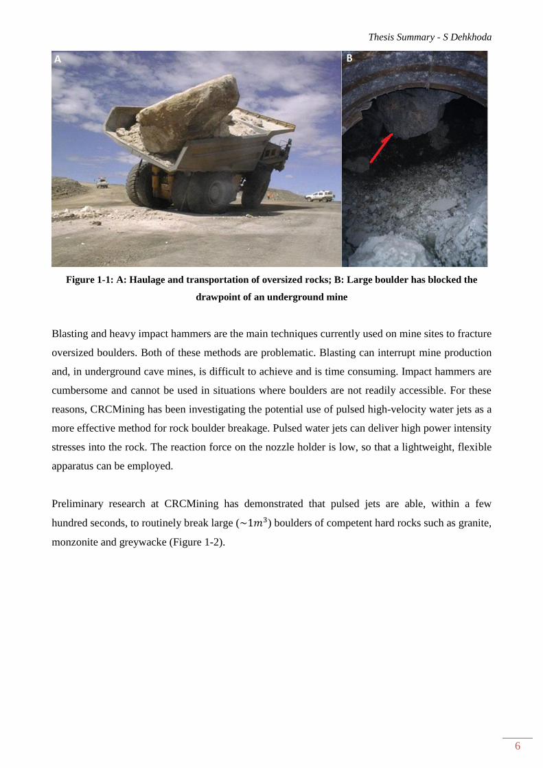
Figure 1-1: A: Haulage and transportation of oversized rocks; B: Large boulder has blocked the
drawpoint of an underground mine
Blasting and heavy impact hammers are the main techniques currently used on mine sites to fracture
oversized boulders. Both of these methods are problematic. Blasting can interrupt mine production
and, in underground cave mines, is difficult to achieve and is time consuming. Impact hammers are
cumbersome and cannot be used in situations where boulders are not readily accessible. For these
reasons, CRCMining has been investigating the potential use of pulsed high-velocity water jets as a
more effective method for rock boulder breakage. Pulsed water jets can deliver high power intensity
stresses into the rock. The reaction force on the nozzle holder is low, so that a lightweight, flexible
apparatus can be employed.
Preliminary research at CRCMining has demonstrated that pulsed jets are able, within a few
hundred seconds, to routinely break large ( ) boulders of competent hard rocks such as granite,
monzonite and greywacke (Figure 1-2).

Thesis Summary - S Dehkhoda
7
Figure 1-2: Examples of the broken samples (greywacke, granite and monzonite) with pulsed
water jet.
Further research has also been conducted worldwide using pulsed water jets to investigate the effect
of operational parameters such as: nozzle diameter, standoff distance, pulse frequency and jet
pressure on rock breakability (Agus et al. 1993; Leach et al. 1966; Vijay, M.M., Remisz & Shen
1993). There is, however, only a limited understanding of the breakage mechanism and this makes

Thesis Summary - S Dehkhoda
8
it difficult to improve the efficiency of the system. There are many fundamental questions, which
have remained unsolved, such as:
What is the type and amount of the applied energy on rock from the impact of a water jet
pulse?
How does the geometry of the pulse (length and diameter) affect the possible damage?
What is the role of pulsation frequency on the quality of fracture and is there any optimum
effective frequency for a rock type?
Where does the governing fracture initiate?
Do the induced stress waves, which are due to the dynamic nature of loading applied by
pulsed water jets, play a significant role in breaking the samples or it is just as a result of the
local hydrodynamics?
Do the sequential impacts cause a fatigue phenomenon in the target?
What is the dominant breakage mechanism? Is it erosion or tensile failure such as spalling
and hydro-fracturing?
The scope of this research was limited to the investigation of the rock breakage mechanism using
pulsed water jets. The characteristics of the water pulses are directly related to the methods
employed for their generation. Since the magnitude and duration of the stress that is applied by a
water pulse is controlled largely by its size (pulse diameter and length) and quality (coherence of
the water pulse), this research initially aimed to investigate the formation of a water pulse using a
simple water-filled chamber and an impacting technique. The quality of the produced water pulse
was analysed using a high-speed video technique, and the magnitude of the induced stress from the
impact of such pulse in a target was studied experimentally. The goal was to develop an
understanding on the quality of the generated water pulses.
Since, however, a pulsed water jet is a series of discrete water pulses, the pulse length and the
separation distance between two sequential pulses are important in the efficacy of the rock breakage
mechanism. This research thus aimed to identify the role and relative importance of these
parameters - pulse length and pulsation frequency, on the rock fracture process. The goal was to
predict the appropriate jet parameters for breaking rock.
Thesis Summary - S Dehkhoda
9
Formation and characteristics of water pulses 2
The development of practical methods for producing high-energy water pulses has always proven
difficult. At one extreme are the water cannons, which provide highly energetic but single pulse
impacts on the target (Edney 1976) and at the other extreme are the very high-frequency and low-
energy pulsed jets, introduced by Vijay (1994), which are formed using an ultrasonic transducer
upstream of the nozzle. These ultrasonically-formed jets have been developed further by Foldyna et
al. (2004). Between these extremes are the so-called self-modulated jets. These use an organ pipe
structure upstream of the nozzle to induce waves in the flow stream. The air drag causes the
continuous jets to break up into a series of pulses when these jets exit the nozzle. These were first
described by Nebeker (1976), and further developed by Chahine et al. (1983). Only the low-energy
ultrasonically formed jets have found a widespread use as a practical device.
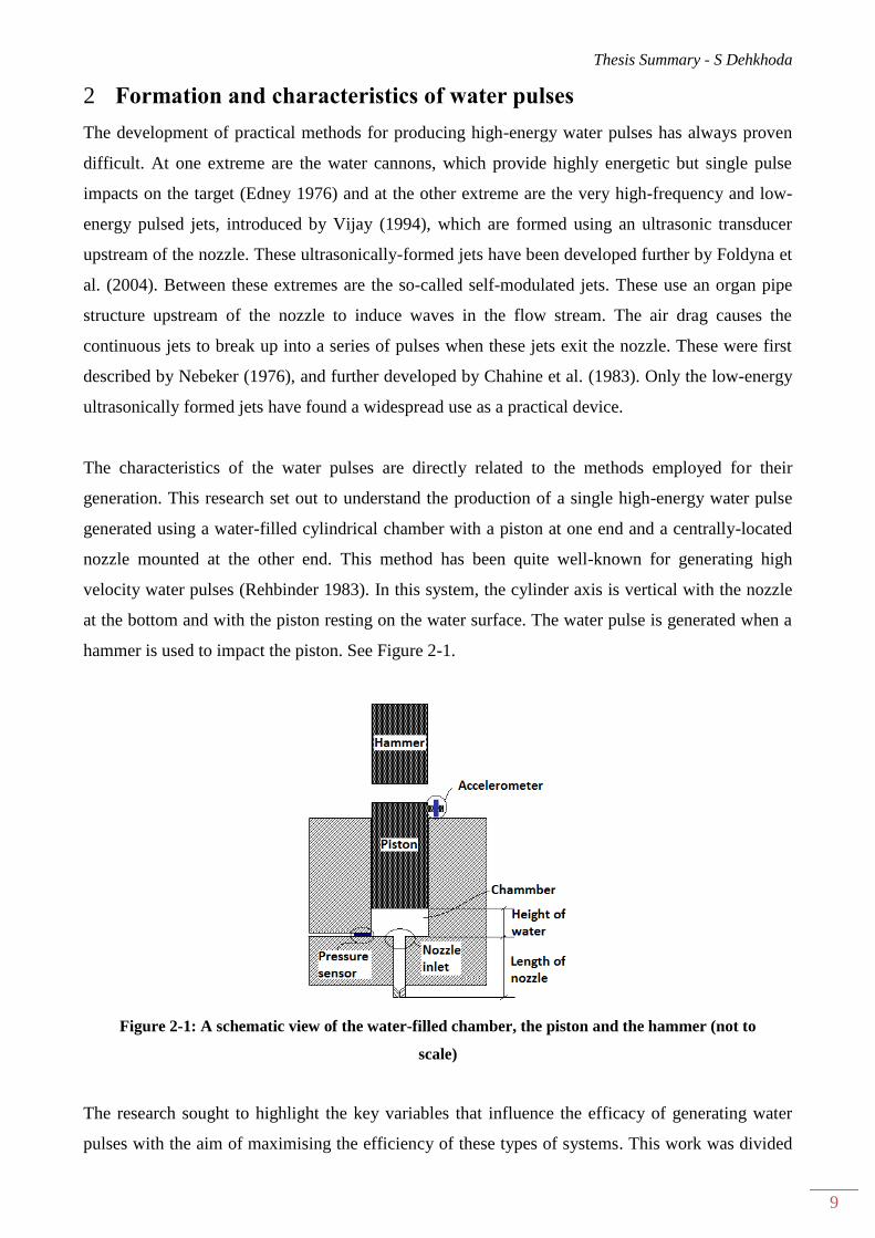
The characteristics of the water pulses are directly related to the methods employed for their
generation. This research set out to understand the production of a single high-energy water pulse
generated using a water-filled cylindrical chamber with a piston at one end and a centrally-located
nozzle mounted at the other end. This method has been quite well-known for generating high
velocity water pulses (Rehbinder 1983). In this system, the cylinder axis is vertical with the nozzle
at the bottom and with the piston resting on the water surface. The water pulse is generated when a
hammer is used to impact the piston. See Figure 2-1.
Figure 2-1: A schematic view of the water-filled chamber, the piston and the hammer (not to
scale)
The research sought to highlight the key variables that influence the efficacy of generating water
pulses with the aim of maximising the efficiency of these types of systems. This work was divided
Thesis Summary - S Dehkhoda
10
into two parts: an analytical study, which investigated the possible arrangements of the design of the
apparatus with the goal of determining the most efficient arrangement, and an experimental study,
which built and tested the selected design. Later additional theoretical studies were conducted in
order to determine whether further refinement of the model was justified or required.
2.1 Formulation of pulse formation
The pressure dynamics inside a water-filled cylindrical chamber that was impacted by a hammer-
piston arrangement was studied. A theoretical and computational model was developed to explain
both the impact mechanism and the phenomenon of pressure build-up in, and release from, the
chamber. The problem to be solved was to calculate the changing water volume in the chamber with
a moveable boundary (the piston) and with water discharging through the nozzle. The equations of
continuity and conservation of mass were applied to relate the movement of the piston to the
discharge from the nozzle. It was assumed that the flow inside the nozzle and the chamber was at
quasi-steady-state and one-dimensional, and the water was inviscid and compressible.
This model postulated that immediately after the collision of the hammer and the piston, as soon as
the piston starts moving, the water inside the chamber compresses and stores energy. The pressure
in the chamber rises, triggering water discharge from the nozzle. The piston slows and eventually
stops as the water approaches a maximum pressure, determined by water’s bulk modulus. This point
corresponds to the maximum attainable pressure at the peak compressibility value. From this
moment, the compressed water expands elastically, and releases the stored energy, lowering the
pressure and reversing the direction of the piston. At this point, depending on the system design, a
second collision will often take place between the hammer and the piston. This causes the piston to
change direction and to recompress the water inside the chamber. A second peak pressure is then
recorded, the magnitude of which is related to the compressibility of the remaining water volume in
the chamber.
The product of the model was a formulation that predicted the pressure history within the chamber.
It was solved for different combinations of the hammer and piston masses in order to find the
optimal combinations of masses, keeping the nozzle diameter and the water column height
unchanged. The model was next used to examine the effect of the height of the water column on the
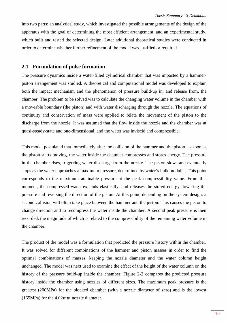
history of the pressure build-up inside the chamber. Figure 2-2 compares the predicted pressure
history inside the chamber using nozzles of different sizes. The maximum peak pressure is the
greatest (200MPa) for the blocked chamber (with a nozzle diameter of zero) and is the lowest
(165MPa) for the 4.02 nozzle diameter.
Thesis Summary - S Dehkhoda
11
Figure 2-2: Pressure history inside the chamber for different nozzle sizes- Analytical model for
quasi-steady-state flow
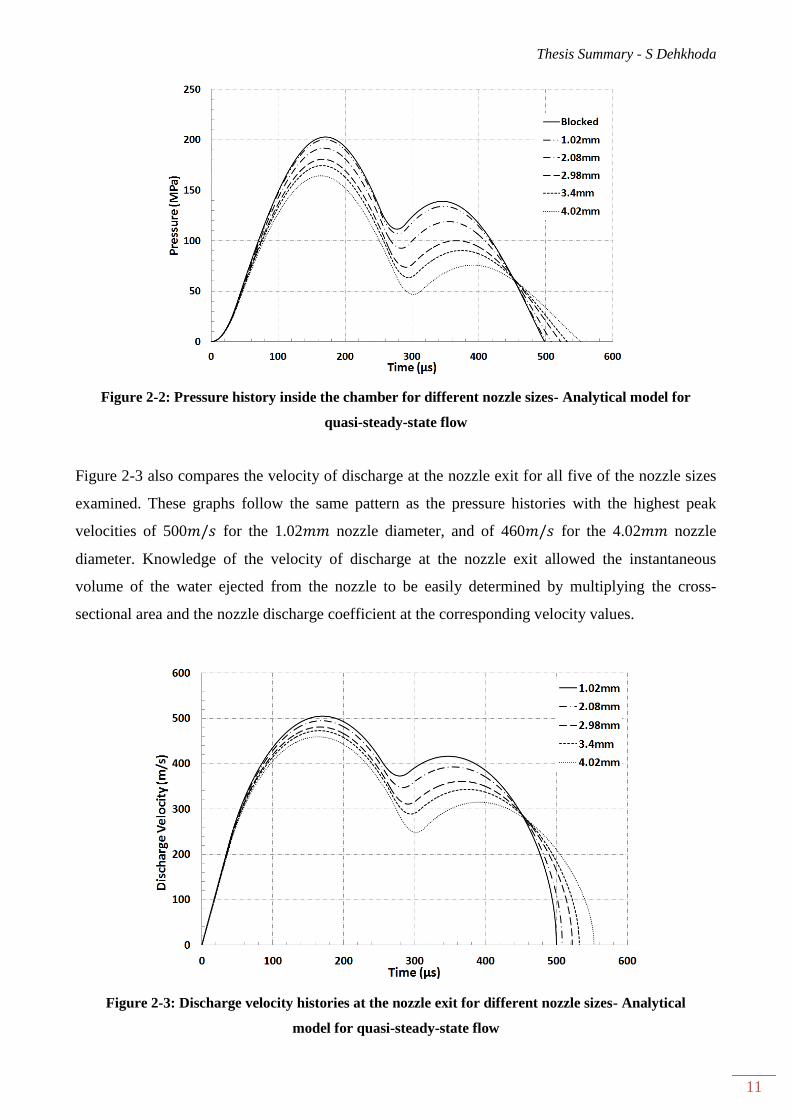
Figure 2-3 also compares the velocity of discharge at the nozzle exit for all five of the nozzle sizes
examined. These graphs follow the same pattern as the pressure histories with the highest peak
velocities of 500 for the 1.02 nozzle diameter, and of 460 for the 4.02 nozzle
diameter. Knowledge of the velocity of discharge at the nozzle exit allowed the instantaneous
volume of the water ejected from the nozzle to be easily determined by multiplying the cross-
sectional area and the nozzle discharge coefficient at the corresponding velocity values.
Figure 2-3: Discharge velocity histories at the nozzle exit for different nozzle sizes- Analytical
model for quasi-steady-state flow

Thesis Summary - S Dehkhoda
12
2.2 Validating experiments
The efficient piston, hammer and chamber system that was defined from the model was built for
experimentation. See Figure 2-4. The hammer was dropped from a height of 6m onto a piston that
was initially resting on the surface of a water-filled cylindrical chamber and the pressure history
within the chamber was recorded during the event using a dynamic pressure sensor that was
mounted flush on the inside wall of the chamber. The experiments were carried out for different
nozzle sizes (1.02 , 2.08 , 2.98 , 3.43 and 4.02 ) and repeated to obtain consistent
pressure profiles.
Figure 2-4: Photograph of the experimental device.
The experimental observations confirmed the behaviour observed from the model. Data from the
pressure sensor mounted in the cylindrical chamber also showed two peak values, the second being
lower than the first. The magnitude of these maximum pressures decreased with increasing nozzle
size. The first peak pressure for the 1.02 nozzle diameter had a magnitude of 200MPa; this
value was reduced to 170MPa for the 4.0 nozzle diameter. An excellent correlation was found
between the theoretical pressure profiles and the recorded experimental data, thus validating the
model (Figure 2-5).
Thesis Summary - S Dehkhoda
13
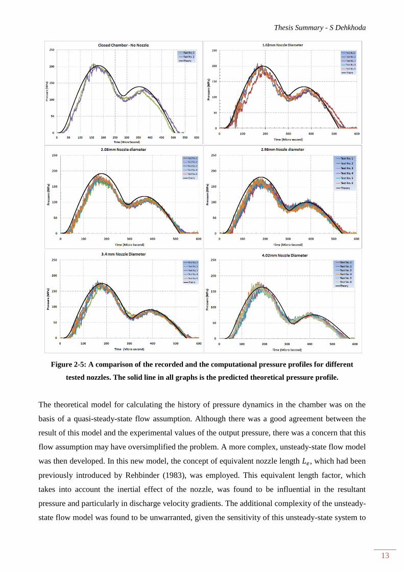
Figure 2-5: A comparison of the recorded and the computational pressure profiles for different
tested nozzles. The solid line in all graphs is the predicted theoretical pressure profile.
The theoretical model for calculating the history of pressure dynamics in the chamber was on the
basis of a quasi-steady-state flow assumption. Although there was a good agreement between the
result of this model and the experimental values of the output pressure, there was a concern that this
flow assumption may have oversimplified the problem. A more complex, unsteady-state flow model
was then developed. In this new model, the concept of equivalent nozzle length , which had been
previously introduced by Rehbinder (1983), was employed. This equivalent length factor, which
takes into account the inertial effect of the nozzle, was found to be influential in the resultant
pressure and particularly in discharge velocity gradients. The additional complexity of the unsteady-
state flow model was found to be unwarranted, given the sensitivity of this unsteady-state system to
Thesis Summary - S Dehkhoda
14
the value of and the fact that the available methods for calculating the value of were
imprecise. The quasi-steady-state flow approach was thus preferred.
Sudden pressure changes, which were manifested as sudden very sharp spikes in the experimental
data, prompted further investigation of the pressure build-up in the chamber based on the
interactions of the stress waves in the whole system - in the hammer, in the piston and in the water
column. A two-step process was used to develop a model using the assumptions of rigid and elastic
bodies. The pressure of the water at the bottom of a closed chamber was determined. Good
correlation was found between the result of the model and the experiments.
Integrity of generated water pulses 3
The magnitude and duration of the stress applied by a water pulse striking a target is controlled
largely by the pulse size (diameter and length) and the pulse quality (coherence and density). The
coherence of the water pulse that was generated by the hammer-piston impacting system was of
concern in this study. If repeated shock reflections within the chamber were transmitted or were
carried into the nozzle’s internal geometry, this could have caused the emerging jet to pulsate.
The formation and the impacting phenomenon of a pulsed water jet occur too fast to be observable
with the naked eye. The coherence of the water pulse produced with the described water-filled
chamber through a 1 diameter nozzle was thus studied using a high-speed video technique. The
aim was to investigate the influence of any induced stress waves within the chamber on pulse
coherence and gain a better understanding and insight of jet formation and pulse consistency.
Two sets of experiments were conducted: the first set was at high-resolution and low frame-rate to
investigate the change in the coherence of the pulse due to air drag; the second set was at low-
resolution and high frame-rate in order to focus on the formation and on the alteration of the shroud
of the droplet spray covering the core of the jet.
The high-speed video demonstrated noticeable sections with density differences and fairly regular
separations in the pulse stream at the early stage of the discharge (Figure 3-1). This was explained
by the presence of travelling stress waves exiting through the liquid inside the nozzle. The results
suggested that there was little if any effect of shock reflections inside the nozzle. The velocity
variance within the pulse, which was associated with the pressure dynamics in the chamber, was
suggested as the main cause of breaking the water pulse into sections of different shape and
velocity.

Thesis Summary - S Dehkhoda
15
Figure 3-1: Generated water pulse through 1.02 nozzle exit in air; Peak pressure 200MPa,
Filming at 4000 , side-light arrangement, time interval between frames 250
The high-speed photographic study also indicated the formation of a large shroud of droplets during
the first 200 of the discharge, which then eased for the last 150 of the discharge (Figure 3-1
and Figure 3-2). The model that was developed showed that, during this early time period, the
velocity of the packets of water exiting the nozzle continuously increased, meaning that the later
packets had a higher velocity than the packets ahead of them. This intense droplet shroud during
this time was then attributed to the interaction of water packets, causing jet break-up and creating a
cloud of mist in front. The part of the jet that followed was a perfect cylinder with a diameter close
to that of the nozzle diameter. This cylindrical part of the jet travelled a distance of ten nozzle
diameters.
As the water particles exited nozzle, forming the water pulse, a relatively large mass of water was
created (frames 11 to 14 in Figure 3-2). Although this mass has a rounded front and looks very
dense, its coherence was questionable. It possibly contained more atomized liquid than the core jet.
The velocity of this pulse mass was calculated at about 480 based on its displacement within
frames. These results revealed that the generated water pulse most possibly was not a single
coherent jet; it was rather broken into discrete sections.
Thesis Summary - S Dehkhoda
16
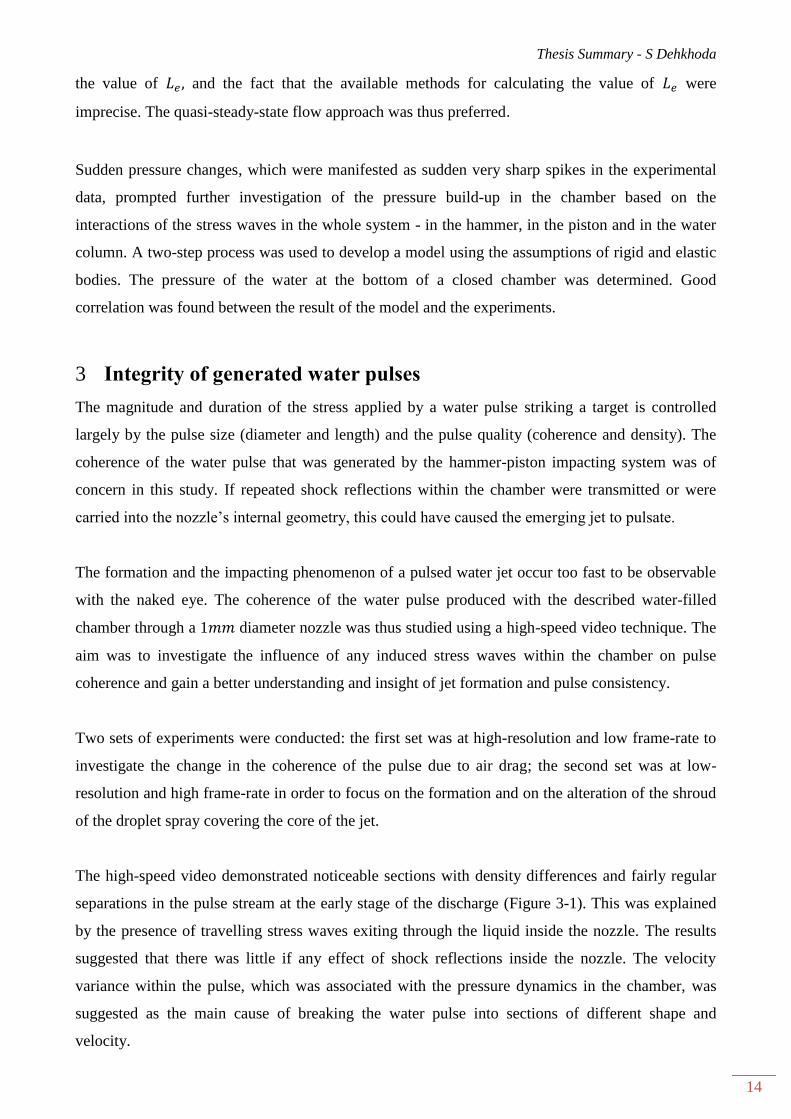
Figure 3-2: Generated water pulse through a 1.02 nozzle exit in air - Peak pressure 200MPa,
High-speed camera filming at 225000 , side and fill-light arrangement, 22.2 time interval
between frames
Theoretical models were also developed to determine the shape of the core of the jet on the basis of
the interaction of the water packets with different velocities. The effect of air drag force was
neglected in these models. The possibility of merging water packets of different velocities to form a
bigger packet was shown to be unlikely. Alternatively, the theory in which the faster water packet
smashed into and destroyed the slower one achieved very acceptable results. The core of the pulse
was found to have a cucumber shape (Figure 3-3) that was covered by a shroud of droplets, which
were formed from the dispersion of the water packets.
Thesis Summary - S Dehkhoda
17
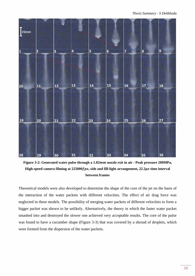
Figure 3-3: Shape of the generated pulse at certain time instants and distances from the nozzle
The model also determined that only 20% of the jet was disturbed thus forming the droplet shroud
whilst the rest stayed in the core. This supported the view that the main part of the jet stays as an
intact core at short distances from the nozzle and that only a small portion of the jet volume
transforms to the shroud of drops.
Impact-induced stress measurement 4
The effectiveness of the generated water pulses using the described water-filled chamber in striking
a target was next investigated. Upon the impact of a high velocity water pulse, a short-duration
high-intensity impulsive stress described as water hammer pressure is applied on target. This is
the result of the compressible behaviour of the water against the target at the initial stages of the
impact. Despite a largely theoretical understanding of the impact phenomenon, the magnitude of the
impact force developed from water impact and the resulting deformation of the surface are not fully
understood. This is mainly due to the transient nature of the phenomenon and to the difficulties in
measuring this force because of the very short impact time (Grinspan & Gnanamoorthy 2010).
Capturing the very short duration water impact event at a very low noise level was the main
challenge in this research. This very short event required a sensor with a sufficiently quick response
time to record enough data points before the water hammer pressure ceases. Figure 4-1 shows a
Thesis Summary - S Dehkhoda
18
possible view of the expected waveform of the generated stress wave in the target from the impact
of a single water pulse. The slope angle of the rising curve depends on the “instantaneous”
material response; whereas the maximum attainable stress is controlled with a viscous relaxation in
the sensor and in the target until equilibrium is reached (Asay et al. 1994). is larger for steel than
for polymers due to its faster response speed.
Figure 4-1: Expected stress wave waveform induced from the impact of a water pulse in a target
The duration of water hammer pressure in Figure 4-1 is largely influenced by the diameter of the
water pulse if the length of the pulse is longer than its diameter.
A PVDF shock gauge was used to capture the stress induced within a target by the water hammer
and the stagnation pressures when a high velocity water pulse was directed normally against the
target. The PVDF film provided a direct measure of stress-derivative or stress-rate signals of a few
nanoseconds duration. Comparison of the measured data with the expected values from the theory
then determined the coherence and shape of the core of the water pulse.
In these experiments, the PVDF gauge was embedded between two pieces of the target material. As
the induced stress was conveyed through the top piece of the target a stable waveform developed
that its profile was directly related the shape of the water pulse. The use of this technique further
resulted in preserving the PVDF gauge from the violent impact of the water jet.
The acoustic impedance of the target material was matched with that of the PVDF film to avoid any
dispersion of the input energy. Kel-f was selected as the suitable material for the target. Kel-f is a
Thesis Summary - S Dehkhoda
19
brand name for a fluorocarbon-based polymer called PolyChloroTriFluoroEthylene. This material
has similar acoustic impedance as the PVDF material.
The target compound (the Kel-F discs and the embedded PVDF gauge) was secured onto a steel
plate. The backing Kel-F piece was located within the plate, supported on its built-in shoulders, and
the top Kel-F piece was maintained in place by the use of a locating ring, which was fixed on the
plate using four equally-spaced screws. See Figure 4-2A. The clamping of the target with the
support of the locating ring compressed the pieces, thus assuring that intimate contact was achieved
for all materials.
The steel plate was mounted on a rigid frame of the water jet apparatus using a rigid holder. See
Figure 4-2B. This holder was designed to have no deflection from the impacting force. The overall
view of the test set-up is illustrated in Figure 4-2C. The standoff distance (the distance from the top
surface of the Kel-F to the nozzle head) was varied from 100 to 120 from one test to the
next.
Figure 4-2: The test set-up of impact pressure measurements; A: schematic view of the target
compound and the plate, B: Schematic view of the plate holder, C: Overall view of the test set-up
The schematic view of the water jet apparatus in relation to the impact pressure measurement set-up
is illustrated in Figure 4-3. The water pulse was generated by dropping a hammer from a height of
Thesis Summary - S Dehkhoda
20
6 onto the top of a piston, which rested on the water-filled chamber equipped with 1 diameter
nozzle size.
Figure 4-3: A schematic view of the pulsed jet apparatus in relation to the impact measurement
set-up (not to scale)
In addition to the PVDF gauge, measurements from an accelerometer, mounted on the piston, and a
PCB pressure sensor, located inside the water chamber, were obtained (Figure 4-3). The
accelerometer monitored the movement of the piston and recorded the instant of impact, whilst the
piezoelectric pressure sensor monitored the pressure history inside the water chamber. The
measurement of the PVDF gauge was synchronised with the accelerometer and the piezoelectric
pressure sensor.
The response of the PVDF gauge was analysed with respect to the measurements from the PCB
pressure gauge, reflecting the history of the pressure dynamics in the reservoir (Figure 4-4). The
time delay between the initiation of the pressure dynamics inside the chamber and that of the PVDF
gauge response was used to determine the velocity of the front of the water pulse. This was found to
be equal to 264 . This impact velocity could theoretically generate a water hammer pressure
with a magnitude of 275MPa and a stagnation pressure equal to 35MPa.
The PVDF shock response to the impact of the single water pulse (Figure 4-4) showed three main
peaks. The study of this signal indicated three discrete impacts that the peak magnitude of these
impacts exhibited an increasing trend with time; the first peak having the lowest stress value and the
Thesis Summary - S Dehkhoda
21
third peak having the highest value. This, indeed, supported the result of the modelling and
experimental work whereby the faster packets of water, which exited the nozzle later in the impact
sequence, disaggregated the front section of the main pulse. It also confirmed that the generated
single water pulse had broken into three discrete sections
Figure 4-4: Comparison of the signal from the PVDF gauge with the signal from the PCB
pressure sensor, which represents the pressure dynamics in the chamber.
Figure 4-5 illustrates the stress waveform induced from the initial impact of the water pulse. The
peak stress reaches a magnitude of 33MPa and then starts declining after 450 . The positive stress
lasts for 1 and is followed by a drop to -10MPa. The stress, after some fluctuations, stabilises at
about 1.37MPa. The data beyond this window was disregarded as it had been contaminated with
interference from the reflected waves.
Figure 4-5: Associated stress on Kel-f from the impact of the water pulse
Thesis Summary - S Dehkhoda
22
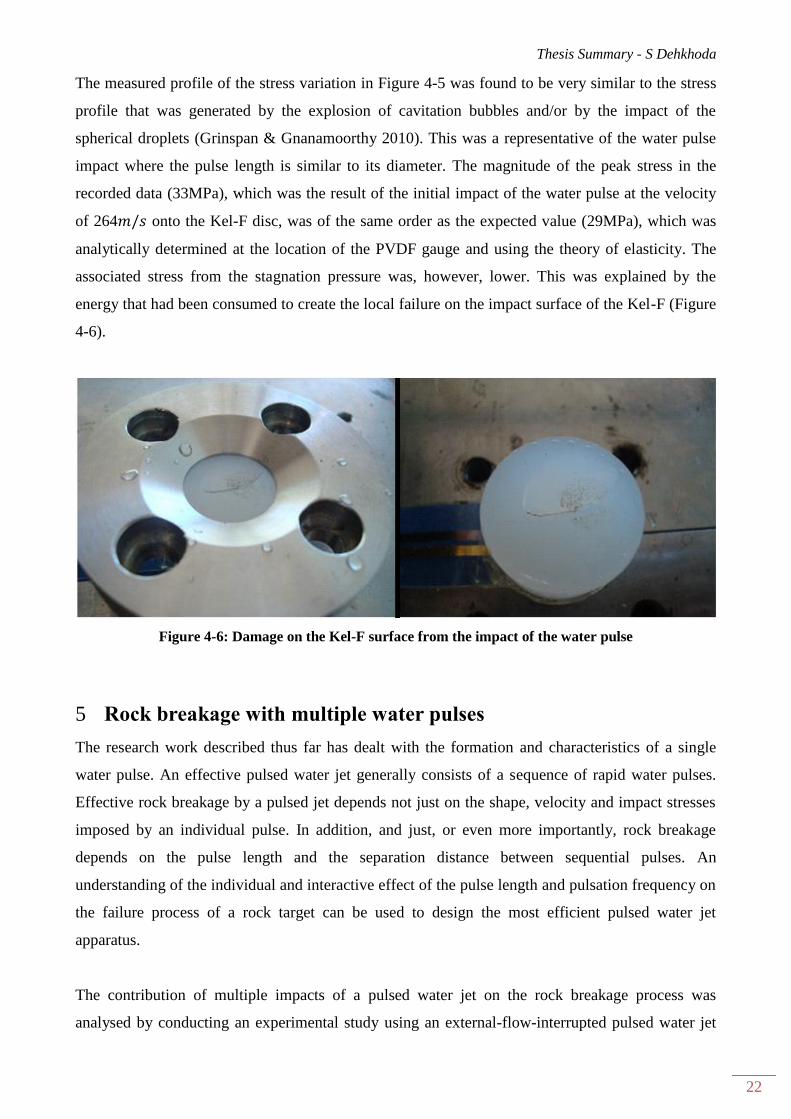
The measured profile of the stress variation in Figure 4-5 was found to be very similar to the stress
profile that was generated by the explosion of cavitation bubbles and/or by the impact of the
spherical droplets (Grinspan & Gnanamoorthy 2010). This was a representative of the water pulse
impact where the pulse length is similar to its diameter. The magnitude of the peak stress in the
recorded data (33MPa), which was the result of the initial impact of the water pulse at the velocity
of 264 onto the Kel-F disc, was of the same order as the expected value (29MPa), which was
analytically determined at the location of the PVDF gauge and using the theory of elasticity. The
associated stress from the stagnation pressure was, however, lower. This was explained by the
energy that had been consumed to create the local failure on the impact surface of the Kel-F (Figure
4-6).
Figure 4-6: Damage on the Kel-F surface from the impact of the water pulse
Rock breakage with multiple water pulses 5
The research work described thus far has dealt with the formation and characteristics of a single
water pulse. An effective pulsed water jet generally consists of a sequence of rapid water pulses.
Effective rock breakage by a pulsed jet depends not just on the shape, velocity and impact stresses
imposed by an individual pulse. In addition, and just, or even more importantly, rock breakage
depends on the pulse length and the separation distance between sequential pulses. An
understanding of the individual and interactive effect of the pulse length and pulsation frequency on
the failure process of a rock target can be used to design the most efficient pulsed water jet
apparatus.
The contribution of multiple impacts of a pulsed water jet on the rock breakage process was
analysed by conducting an experimental study using an external-flow-interrupted pulsed water jet
Thesis Summary - S Dehkhoda
23
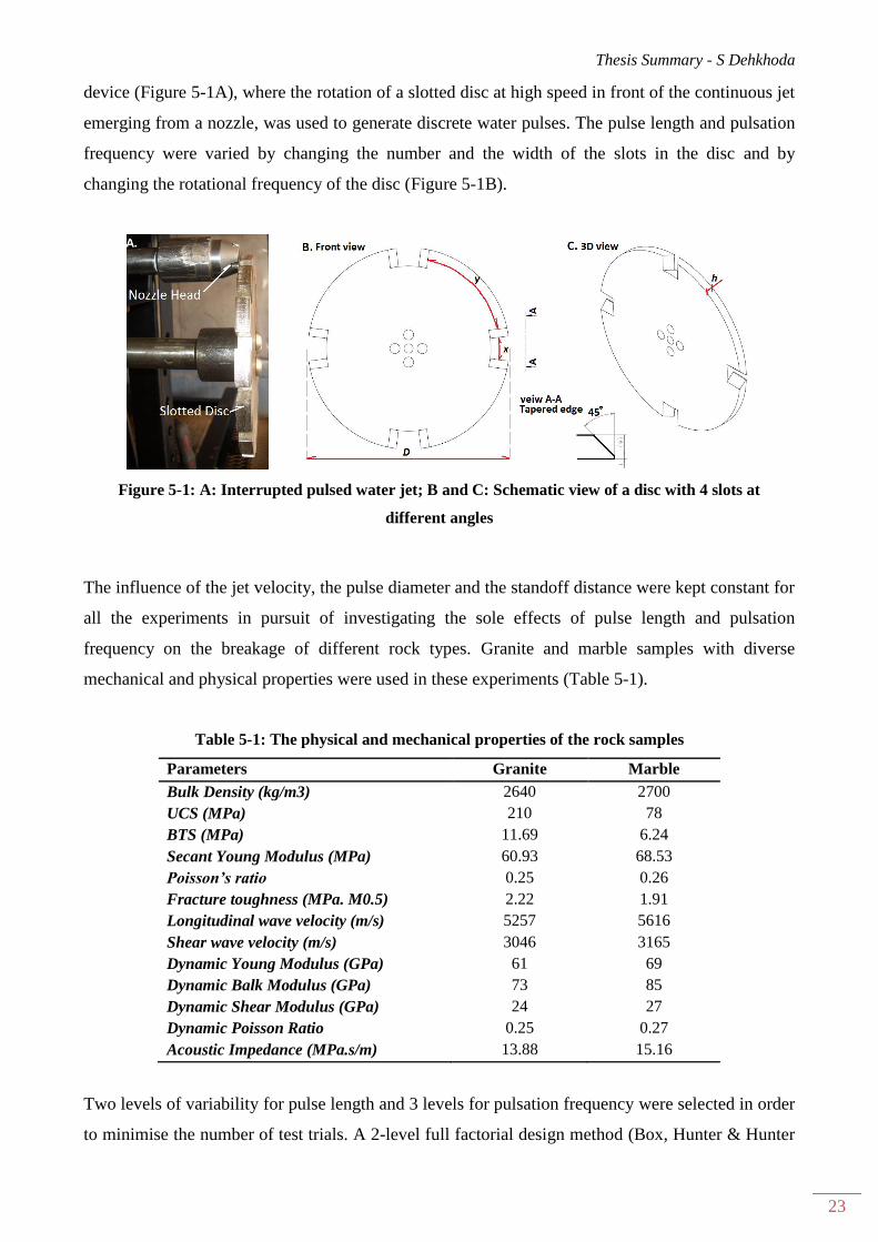
device (Figure 5-1A), where the rotation of a slotted disc at high speed in front of the continuous jet
emerging from a nozzle, was used to generate discrete water pulses. The pulse length and pulsation
frequency were varied by changing the number and the width of the slots in the disc and by
changing the rotational frequency of the disc (Figure 5-1B).
Figure 5-1: A: Interrupted pulsed water jet; B and C: Schematic view of a disc with 4 slots at
different angles
The influence of the jet velocity, the pulse diameter and the standoff distance were kept constant for
all the experiments in pursuit of investigating the sole effects of pulse length and pulsation
frequency on the breakage of different rock types. Granite and marble samples with diverse
mechanical and physical properties were used in these experiments (Table 5-1).
Table 5-1: The physical and mechanical properties of the rock samples
Parameters Granite Marble
Bulk Density (kg/m3) 2640 2700
UCS (MPa) 210 78
BTS (MPa) 11.69 6.24
Secant Young Modulus (MPa) 60.93 68.53
Poisson’s ratio 0.25 0.26
Fracture toughness (MPa. M0.5) 2.22 1.91
Longitudinal wave velocity (m/s) 5257 5616
Shear wave velocity (m/s) 3046 3165
Dynamic Young Modulus (GPa) 61 69
Dynamic Balk Modulus (GPa) 73 85
Dynamic Shear Modulus (GPa) 24 27
Dynamic Poisson Ratio 0.25 0.27
Acoustic Impedance (MPa.s/m) 13.88 15.16
Two levels of variability for pulse length and 3 levels for pulsation frequency were selected in order
to minimise the number of test trials. A 2-level full factorial design method (Box, Hunter & Hunter
Thesis Summary - S Dehkhoda
24
1976) with 3 factors or independent variables (rock type, pulse length and pulsation frequency) was
used to create the test matrix. Table 5-2 summarises all the independent variables and their level of
variations in the experiments.
Table 5-2: Test parameters
Independent Variable Dimension Levels Test Conditions
Jet velocity m/s 1 348
Confining pressure MPa 1 6
Exposure time s 1 15(granite), 5 (marble)
Pulse diameter mm 1 3.4
Standoff distance mm 1 100
Pulse length mm 2 458,888
Frequency of pulse Hz 3 53,106, 212
Rock type - 2 Granite, Marble
The dependant variable in the experiments was the amount of damage caused in the rock samples.
The main challenge in this regard was to control the fracture so that one test could be compared
with another. This was addressed by using core samples of competent (no obvious visible fractures)
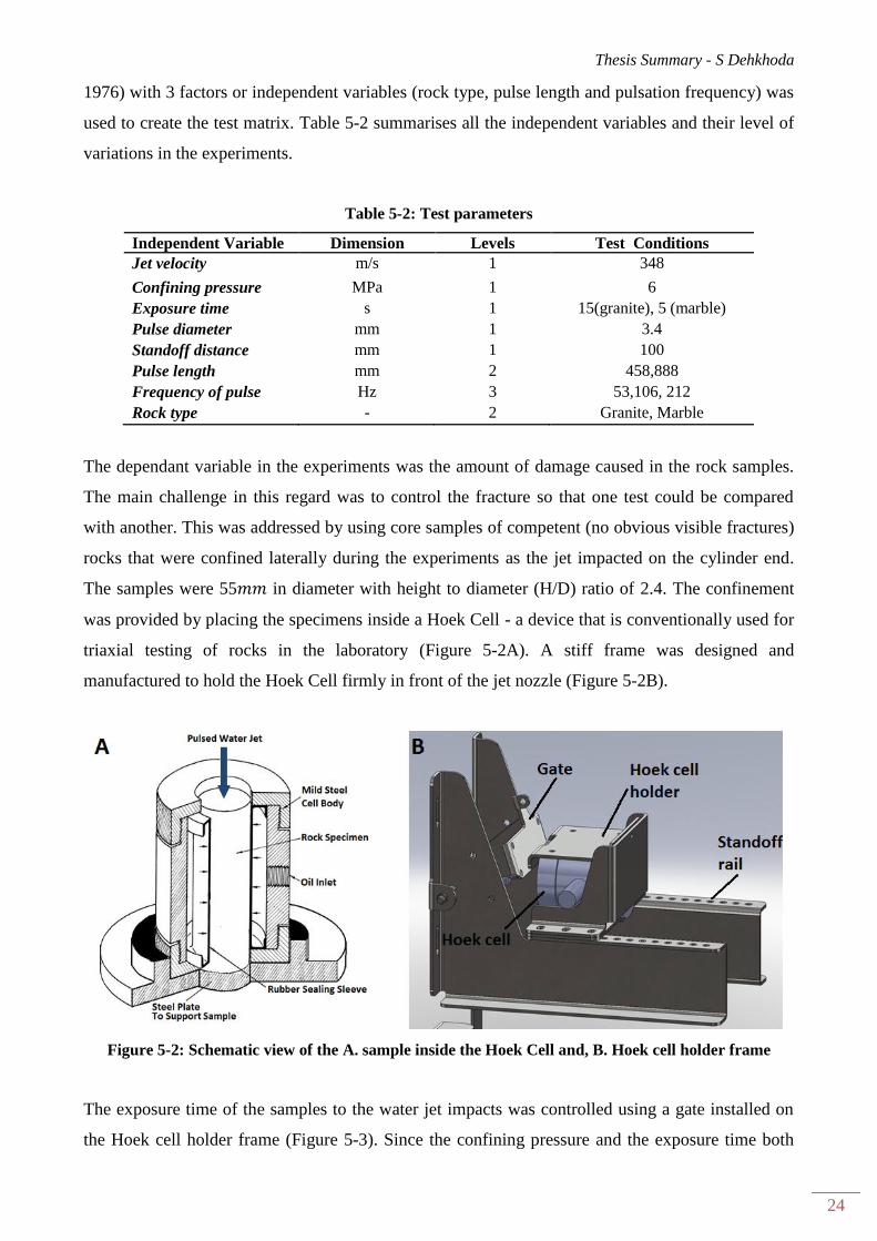
rocks that were confined laterally during the experiments as the jet impacted on the cylinder end.
The samples were 55 in diameter with height to diameter (H/D) ratio of 2.4. The confinement
was provided by placing the specimens inside a Hoek Cell - a device that is conventionally used for
triaxial testing of rocks in the laboratory (Figure 5-2A). A stiff frame was designed and
manufactured to hold the Hoek Cell firmly in front of the jet nozzle (Figure 5-2B).
Figure 5-2: Schematic view of the A. sample inside the Hoek Cell and, B. Hoek cell holder frame
The exposure time of the samples to the water jet impacts was controlled using a gate installed on
the Hoek cell holder frame (Figure 5-3). Since the confining pressure and the exposure time both

Thesis Summary - S Dehkhoda
25
affected the breaking ability of the pulsed water jet, these two variables were kept constant and
identical for all the experiments. A static pressure gauge was mounted on the Hoek cell (see Figure
5-3) to record the possible variance in the confining pressure during the experiment.
Figure 5-3: The Hoek cell test, overview of the frame and instrumentation devices
The independent variables (pulse length and pulsation frequency) were changed by using perforated
discs of various slot numbers and slot lengths (Table 5-3) and the experiments were carried out on
marble and granite to study the breakage mechanism. The local failure, as well as the internal
breakdown were of interest and thus monitored.
Table 5-3: Pulse length and pulsation frequency for different discs
Operational parameter
Jet dia. 3.4 mm Disc Rotation 795 rpm Pump Pressure 80 MPa
Disc dia. 210 mm Disc Linear Vel. 8.74 m/s Jet vel. 348 m/s
Disc No. Slot width
mm
Spoke width mm Number of
slots
Pulsation
frequency (Hz)
Pulse length
(mm)
2 14.9 150.1 4 53 458
3 25.7 139.2 4 53 888
5 14.9 67.6 8 106 458
6 25.7 56.7 8 106 888
8 14.9 26.4 16 212 458
9 25.7 15.5 16 212 888
Thesis Summary - S Dehkhoda
26
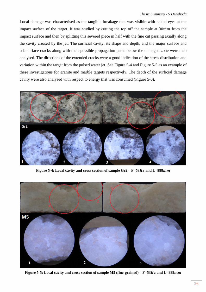
Local damage was characterised as the tangible breakage that was visible with naked eyes at the
impact surface of the target. It was studied by cutting the top off the sample at 30 from the
impact surface and then by splitting this severed piece in half with the fine cut passing axially along
the cavity created by the jet. The surficial cavity, its shape and depth, and the major surface and
sub-surface cracks along with their possible propagation paths below the damaged zone were then
analysed. The directions of the extended cracks were a good indication of the stress distribution and
variation within the target from the pulsed water jet. See Figure 5-4 and Figure 5-5 as an example of
these investigations for granite and marble targets respectively. The depth of the surficial damage
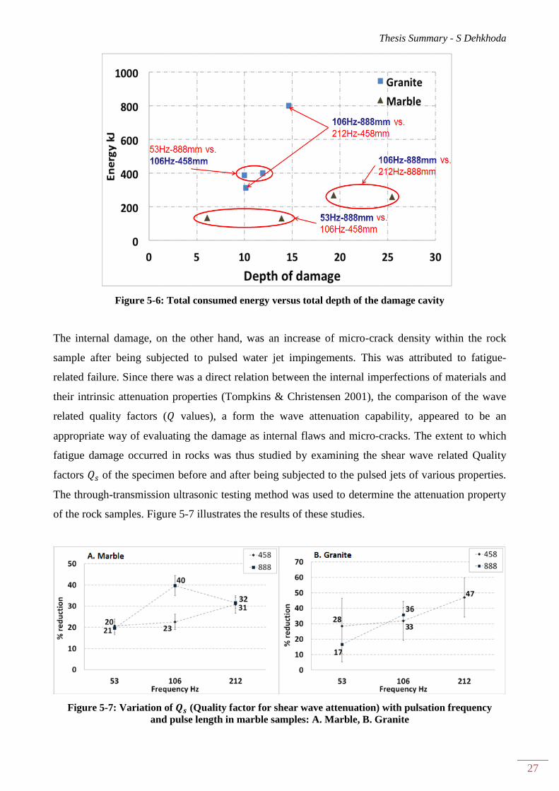
cavity were also analysed with respect to energy that was consumed (Figure 5-6).
Figure 5-4: Local cavity and cross section of sample Gr2 – F=53 and L=888
Figure 5-5: Local cavity and cross section of sample M5 (fine-grained) – F=53 and L=888
Thesis Summary - S Dehkhoda
27
Figure 5-6: Total consumed energy versus total depth of the damage cavity
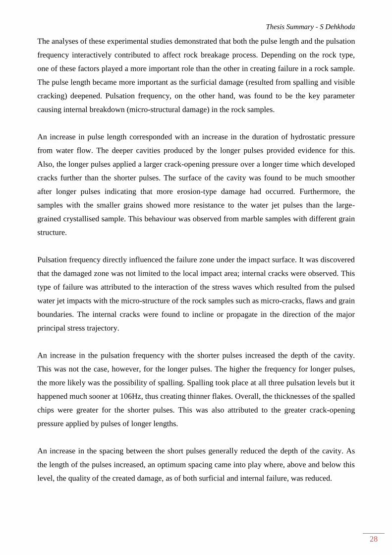
The internal damage, on the other hand, was an increase of micro-crack density within the rock
sample after being subjected to pulsed water jet impingements. This was attributed to fatigue-
related failure. Since there was a direct relation between the internal imperfections of materials and
their intrinsic attenuation properties (Tompkins & Christensen 2001), the comparison of the wave
related quality factors ( values), a form the wave attenuation capability, appeared to be an
appropriate way of evaluating the damage as internal flaws and micro-cracks. The extent to which
fatigue damage occurred in rocks was thus studied by examining the shear wave related Quality
factors of the specimen before and after being subjected to the pulsed jets of various properties.
The through-transmission ultrasonic testing method was used to determine the attenuation property
of the rock samples. Figure 5-7 illustrates the results of these studies.
Figure 5-7: Variation of (Quality factor for shear wave attenuation) with pulsation frequency
and pulse length in marble samples: A. Marble, B. Granite
Thesis Summary - S Dehkhoda
28
The analyses of these experimental studies demonstrated that both the pulse length and the pulsation
frequency interactively contributed to affect rock breakage process. Depending on the rock type,
one of these factors played a more important role than the other in creating failure in a rock sample.
The pulse length became more important as the surficial damage (resulted from spalling and visible
cracking) deepened. Pulsation frequency, on the other hand, was found to be the key parameter
causing internal breakdown (micro-structural damage) in the rock samples.
An increase in pulse length corresponded with an increase in the duration of hydrostatic pressure
from water flow. The deeper cavities produced by the longer pulses provided evidence for this.
Also, the longer pulses applied a larger crack-opening pressure over a longer time which developed
cracks further than the shorter pulses. The surface of the cavity was found to be much smoother
after longer pulses indicating that more erosion-type damage had occurred. Furthermore, the
samples with the smaller grains showed more resistance to the water jet pulses than the large-
grained crystallised sample. This behaviour was observed from marble samples with different grain
structure.
Pulsation frequency directly influenced the failure zone under the impact surface. It was discovered
that the damaged zone was not limited to the local impact area; internal cracks were observed. This
type of failure was attributed to the interaction of the stress waves which resulted from the pulsed
water jet impacts with the micro-structure of the rock samples such as micro-cracks, flaws and grain
boundaries. The internal cracks were found to incline or propagate in the direction of the major
principal stress trajectory.
An increase in the pulsation frequency with the shorter pulses increased the depth of the cavity.
This was not the case, however, for the longer pulses. The higher the frequency for longer pulses,
the more likely was the possibility of spalling. Spalling took place at all three pulsation levels but it
happened much sooner at 106Hz, thus creating thinner flakes. Overall, the thicknesses of the spalled
chips were greater for the shorter pulses. This was also attributed to the greater crack-opening
pressure applied by pulses of longer lengths.
An increase in the spacing between the short pulses generally reduced the depth of the cavity. As
the length of the pulses increased, an optimum spacing came into play where, above and below this
level, the quality of the created damage, as of both surficial and internal failure, was reduced.
Thesis Summary - S Dehkhoda
29
The individual and interactive effect of the pulse length and pulsation frequency on the failure
process of a rock target varied with the physical properties of the rock especially with its brittleness.
A promising correlation was found between the brittleness index factor of the rock samples and
their response behaviour to pulsed water jet impacts. Pulsation frequency was identified as the key
influential factor on the failure of very brittle rock samples. In less brittle material, however, as the
frequency of pulsation increased, the pulse length became an essential factor.
In summary, the pulsation frequency was found responsible for creating a failure zone directly
under the impacted surface. The pulse length, however, controlled the development of this failure
zone by influencing the crack propagation process. The latter influenced the length of time that high
pressure was applied to drive the crack propagation process. Hence longer pulses were required to
propagate cracks as the depth of damage increased.
Conclusions 6
The impacts from high-velocity water pulses apply substantial amounts of energy onto a rock target
surface which directly results in rock damage and rock breakage. These impacts also induce stress
waves within the target. High-energy impacts and the interaction of the release waves (the reflected
tensile waves from interfaces) within the body and at the surface of the target were found to be
responsible for creating localised fracture zones in the vicinity of the impact surface. The pulsation
frequency, by controlling the number of the impacts, is responsible for creating this failure zone. It
was discovered that successive impacts initiate fatigue in the target by introducing micro-structural
damage which contributes significantly to the ultimate failure.
The length of the water pulses was found to control the hydrostatic pressure that was induced in the
cracks and cavities which had been created by the impact of previous water pulses. This provided
the crack-opening pressure thus driving crack propagation, thereby affecting the development of the
failure zone. However, crack growth can be interrupted by energy dissipation and by toughening
mechanisms. The latter includes crack shielding, crack deflection, crack arresting, crack bridging
and crack progression through the rock grains. This is where the appropriate design of operational
factors such as pulse length and pulsation frequency can play a significant role in improving the
failure process of the rock.
The static and dynamic failure behaviour of the rock, as well as its brittleness index were found to
be important characteristics when selecting a pulsed water jet with a suitable pulse length and
pulsation frequency.

Thesis Summary - S Dehkhoda
30
These findings are based on the assumption that the water pulses are coherent and well-separated. It
must be recognised that the method employed for the generation of water pulses is very influential
on the shape and on the quality of the pulses. The energy delivered by a water pulse that is produced
using the impacting technique and a water-filled chamber showed that the developed water pulse
stream is broken into sections of different velocities. The stress within the target that is struck by
such a pulse clearly confirmed the occurrence of the water hammer pressure. The duration of the
water hammer pressure lasted for 1 . The stress induced by the stagnation pressure was influenced
by the interference of the release waves.
This research successfully achieved it stated goals but some aspects of the rock-breakage
mechanism subjected to a pulsed water jet needs more study. The role of the different factors such
as pulse length, pulsation frequency, induced stress waves and dynamic fatigue phenomenon in
failure of rocks has been identified, but the research still cannot specifically recommend an ideal
pulsed water jet with certain operational parameters for the most effective breakage of different
rock types. This is mostly due to the fact that the physical properties and the failure behaviour of
specific rock types affect the efficacy of the pulsed jet.
Reference 7
Agus, M, Bortolussi, A, Ciccu, R, Kim, WM & Manca, PP 1993, 'The influence of rock properties
on water jet performance', in M Hashish (ed.), Proceedings of the Seventh US Water Jet
Conference, Seattle, Washington, vol. 1, pp. 427-42.
Asay, BW, Ramsay, JB, Anderson, MU & Graham, RA 1994, 'Shock response of the commercial
high explosive Datasheet', Shock Waves, vol. 3, no. 4, pp. 267-71.
Box, GEP, Hunter, WG & Hunter, JS 1976, 'Statistics for experiments', in pp. 306-50.
Chahine, GL, Conn, AF & Johnson, VE 1983, 'Cleaning and cutting with self-resonating pulsed
water jets', in 2nd U.S. Water Jet Symposium, Rolla, pp. 238-53.
Edney, BE 1976, 'Experimental studies of pulsed water jets', in HS Stephens, NG Coles & CA
Stapleton (eds), Proceedings of the Third International Symposium on Jet Cutting Technology,
Chicago IL USA, pp. B2:11-B2:26.
Farmer, IW & Attewell, PB 1965, 'Rock penetration by high velocity water jet: A review of the
general problem and an experimental study', International Journal of Rock Mechanics and Mining
Sciences, vol. 2, no. 2, pp. 135-53.
Foldyna, J, Heiniger, K, Mettler, S, Sitek, L & Scucka, J 2007, 'Enhancing of the water jet effects
by pulsation', Manufacturing Engineering, no. 4 (year VI), pp. 30-3.
Thesis Summary - S Dehkhoda
31
Foldyna, J, Sitek, L, Svehla, B & Svehla, S 2004, 'Utilization of ultrasound to enhance high-speed
water jet effects ', Ultrasonics Sonochemistry, vol. 11, no. 3-4, pp. 131-7.
Grinspan, AS & Gnanamoorthy, R 2010, 'Impact force of low velocity liquid droplets measured
using piezoelectric PVDF film', Colloids and surfaces A: Physicochemical and Engineering
Aspects, vol. 356, no. 1-3, pp. 162-8.
Hood, M 1976, 'Cutting strong rock with a drag bit assisted by high pressure water jets', Journal of
the South African Institute of Mining and Metallurgy, vol. 77, no. 4, pp. 79-90.
Leach, SJ, Walker, GL, Smith, AV, Farmer, IW & Taylor, G 1966, 'Some aspects of rock cutting by
high speed water jets [and discussion]', Philosophical Transactions of the Royal Society of London.
Series A, Mathematical and Physical Sciences, vol. 260, no. 1110, pp. 295-310.
Nebeker, EB 1987, 'Percussive jets - State of the art', in M Hood & D Dornfeld (eds), Proceedings
of the Fourth US Water Jet Conference, The University of California Berkeley US, pp. 32-45.
Nebeker, EB & Rodriguez, SE 1976, 'Percussive water jets for rock cutting', in HS Stephens, NG
Coles & CA Stapleton (eds), Proceedings of the Third International Symposium on Jet Cutting
Technology, Chicago IL USA, pp. B1:-B:9.
Ni, H, Wang, R & Du, Y 2011, 'Numerical simulation and experimental study on rock breaking
under pulse water jet', The Electronic Journal of Geotechnical Engineering, vol. 16, no. H, pp. 797-
810.
Rehbinder, G 1983, 'Investigation of water jet pulses generated by an impact piston device', Applied
Scientific Research, vol. 40, no. 1, pp. 7-37.
Tompkins, MJ & Christensen, NI 2001, 'Ultrasonic P- and S-wave attenuation in oceanic basalt',
Geophysics Journal International, vol. 145, no. 1, pp. 172-86.
Vijay, MM 1994, 'Power of pulsed liquid jets', in Z Rakowski (ed.), Geomechanics 93: Proceedings
of the International Conference, Hradec Ostrava Czech Republic, pp. 265-74.
Vijay, MM, Foldyna, J & Remisz , J 1994, 'Ultrasonic modulation of high-speed water jets', in Z
Rakowski (ed.), Geomechanics 93: Proceedings of the International Conference, Hradec Ostrava
Czech Republic, pp. 327-32.
Vijay, MM, Remisz, J & Shen, X 1993, 'Potential of pulsed water jets for cutting and fracturing of
hard rock formations', International Journal of Surface Mining, Reclamation and Environment, vol.
7, no. 3, pp. 121-32.