Experimental and numerical investigation of the sliding ...€¦ · Experimental and numerical...
11
Experimental and numerical investigation of the sliding behaviour of a set of two rigid blocks subjected to cyclic shear-type loads G. C. Manos, V. Kourtides, M. Demosthenous & E. Tsakmakides Department of Civil Engineering, Aristotle University, Thessaloniki, Greece Abstract The aim of this paper is to study the shear transfer mechanism through the horizontal contact surface of two rigid blocks. The shear resistance offered by this contact interface is the main mechanism mobilized by the structural elements of many ancient stone dry-masonry structures in order to transfer horizontal actions from earthquakes and wind forces to the foundation. In some cases a certain connection exists between two blocks at the contact surface, which is materialized by wooden or metal parts at the central area of the blocks (poles, empolia). The role of this connection in transferring horizontal forces and its influence on the seismic behaviour is a point long debated by the research community. Cyclic experiments were performed at the laboratory of Strength of Materials and Structures of Aristotle University of Thessaloniki-Greece in order to study this sliding behaviour at the interface between two rigid blocks. The experimental sequence under investigation can be divided into two groups. The first group includes specimens without any connection between the rigid blocks, while the second group includes specimens with poles and empolia connecting the rigid blocks. During all tests the imposed cyclic horizontal sliding displacement was combined with constant level of vertical load applied at the top of the upper block. Through this experimental process, it became possible to describe the shear transfer mechanism through diagrams of horizontal sliding displacement versus horizontal load, and study the effects on the shear transfer behaviour between these rigid blocks without or with the connection with poles and empolia between them. Numerical finite element simulations of this shear transfer mechanism were also performed utilizing two commercial Finite Element Software packages. Keywords: ancient temples, ancient columns, rigid blocks, poles, empolia. Structural Studies, Repairs and Maintenance of Heritage Architecture X 633 © 2007 WIT Press WIT Transactions on The Built Environment, Vol 95, www.witpress.com, ISSN 1743-3509 (on-line) doi:10.2495/STR070591
Transcript of Experimental and numerical investigation of the sliding ...€¦ · Experimental and numerical...

Experimental and numerical investigation of the sliding behaviour of a set of two rigid blocks subjected to cyclic shear-type loads
G. C. Manos, V. Kourtides, M. Demosthenous & E. Tsakmakides Department of Civil Engineering, Aristotle University, Thessaloniki, Greece
Abstract
The aim of this paper is to study the shear transfer mechanism through the horizontal contact surface of two rigid blocks. The shear resistance offered by this contact interface is the main mechanism mobilized by the structural elements of many ancient stone dry-masonry structures in order to transfer horizontal actions from earthquakes and wind forces to the foundation. In some cases a certain connection exists between two blocks at the contact surface, which is materialized by wooden or metal parts at the central area of the blocks (poles, empolia). The role of this connection in transferring horizontal forces and its influence on the seismic behaviour is a point long debated by the research community. Cyclic experiments were performed at the laboratory of Strength of Materials and Structures of Aristotle University of Thessaloniki-Greece in order to study this sliding behaviour at the interface between two rigid blocks. The experimental sequence under investigation can be divided into two groups. The first group includes specimens without any connection between the rigid blocks, while the second group includes specimens with poles and empolia connecting the rigid blocks. During all tests the imposed cyclic horizontal sliding displacement was combined with constant level of vertical load applied at the top of the upper block. Through this experimental process, it became possible to describe the shear transfer mechanism through diagrams of horizontal sliding displacement versus horizontal load, and study the effects on the shear transfer behaviour between these rigid blocks without or with the connection with poles and empolia between them. Numerical finite element simulations of this shear transfer mechanism were also performed utilizing two commercial Finite Element Software packages. Keywords: ancient temples, ancient columns, rigid blocks, poles, empolia.
Structural Studies, Repairs and Maintenance of Heritage Architecture X 633
© 2007 WIT PressWIT Transactions on The Built Environment, Vol 95, www.witpress.com, ISSN 1743-3509 (on-line) doi:10.2495/STR070591

1 Introduction
The sliding behaviour of cubic rigid blocks, lying one on the top of the other, is examined in this paper. Manos et al [1–3], studied the dynamic response of models of ancient columns or colonnades subjected to horizontal base motions. The successful behaviour of such rigid body assemblages under earthquake loading depends on the friction mechanism which develops between their blocks. In the current investigation two groups of specimens were studied. Initially, a group of two rigid block specimens, made either of steel or marble without poles and empolia between them, have been subjected to shear cyclic loading (Figures 1 and 2). For both groups the contact surface was made in such a way that as best a fit as possible could be achieved between the two blocks at their contact surface. For the steel blocks this was achieved by proper machining; for the marble blocks, apart from cutting and fitting the two blocks together by a marble mason, the two blocks were then rotated against each other when in contact in order to treat the contact surface in this way. The second group studies the influence of poles and empolia on the total shear behaviour when they are introduced between two rigid blocks.
Figure 1: Pole and empolia positioning in an ancient monument and pole and empolio dimensions.
The experimental investigation included series of tests performed at the University of Thessaloniki, whereby the lower block was kept fixed when the upper block was displaced horizontally in its axis of symmetry, resulting in a shear type of loading (Figure 2). This cyclic displacement sequence was accompanied by applying a vertical load, which was imposed on top of the upper block. The vertical load was imposed on the block assembly utilizing a hydraulic actuator in its load-controlled mode aiming to keep the applied vertical load constant at the desired level throughout each test. Finally, the variation of the cyclic horizontal load as well as of the vertical load was monitored throughout all the test sequence. Lourenco and Ramos [4] has performed similar experiments studying the behaviour of dry masonry by subjecting sandstone blocks to cyclic shear loading at the University of Minho, Portugal.
100 mm
100 mm 8 0 mm
8 0 mm
60mm
Pole
Empolio
634 Structural Studies, Repairs and Maintenance of Heritage Architecture X
© 2007 WIT PressWIT Transactions on The Built Environment, Vol 95, www.witpress.com, ISSN 1743-3509 (on-line)
The numerical investigation that followed the experimental sequence utilizes two commercial finite element package [6, 7]. For the numerical simulation of the observed sliding response the two blocks are assumed to behave as rigid bodies remaining elastic for all levels of applied load. Sliding is simulated as a non-linear behaviour at the contact surface (Lourenco [5]). Coulomb-type failure criteria are utilized in an effort to reproduce the sliding response which was observed during the experiments. The effect induced by the variation of the frictional mechanical parameters, when combined with the adopted failure criteria in reproducing numerically the observed behaviour, is presented and discussed here. The results of the experimental investigation show that the sliding behaviour that develops between these two rigid blocks is nearly elasto-plastic. The numerical simulation is validated by comparing the numerical predictions with the corresponding measured values.
Figure 1 (continued).
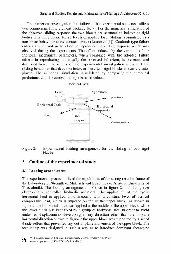
Figure 2: Experimental loading arrangement for the sliding of two rigid blocks.
2 Outline of the experimental study
2.1 Loading arrangement
The experimental process utilized the capabilities of the strong reaction frame of the Laboratory of Strength of Materials and Structures of Aristotle University of Thessaloniki. The loading arrangement is shown in figure 2, mobilizing two electronically controlled hydraulic actuators. The application of the cyclic horizontal load is applied simultaneously with a constant level of vertical compressive load, which is imposed on top of the upper block. As shown in figure 2, the horizontal force was applied at the middle of the upper block, while the lower block was kept fixed by a group of horizontal ties. In order to avoid undesired displacements developing at any direction other than the in-plane horizontal direction shown in figure 2 the upper block was supported by a set of 4 side-rollers that prevented any out of plane movement of the upper block. The test set up was designed in such a way as to introduce dominant shear-type
Horizontal supports
SpecimenLoad cells
Vertical Jack
Horizontal Jack
Steel support
Upper block
Lower
Contact surface
Structural Studies, Repairs and Maintenance of Heritage Architecture X 635
© 2007 WIT PressWIT Transactions on The Built Environment, Vol 95, www.witpress.com, ISSN 1743-3509 (on-line)

behaviour at the interface between the two blocks under a uniform normal stress distribution, which was kept constant throughout each test [2].
2.2 Rigid block specimens
Two groups of rigid block specimens are utilized. The first group is made of steel with relatively smooth contact surface achieved by special machining. The steel specimen dimensions are:
530mm x 528mm in plan and 315mm height for the upper steel block 425mm x 424mm in plan and 220mm height for the lower steel block
The second group is made of white marble (Kavala Greek Type) with the contact interface resulting after cutting and fitting the two blocks together by a marble mason. These blocks were then rotated against each other, when in contact, in order to smooth the contact surface. The overall dimensions of the marble blocks are:
500mm x 500mm in plan and 300mm height for the upper marble block, 400mm x 400mm in plan and 200mm height for the lower marble block.
The pole dimensions are the same for all the cases of rigid blocks tested. The diameter of the selected pole was varied between 10mm and 40mm. Amongst the various materials used for the pole was dogwood (krania). In figure 1, the dimensions of an empolio are also depicted. The material selected for the empolia was either lead or various types of wood. The experiments that were carried out utilizing a steel reaction frame are:
i) Specimen Σ1 steel rigid blocks without pole-empolia ii) Specimen Σ2 marble rigid blocks without pole-empolia iii) Specimen Σ3 steel rigid blocks with pole made of dogwood
(krania) and empolia made of lead.
2.3 Experimental measurements and results
The constant compressive load, normal to the interface, was applied before the imposition of the cyclic horizontal displacement. Two levels of applied compressive load were employed which resulted in equivalent 0.25 Mpa uniform normal stress level at the contact surface for the steel blocks and 0.125 Mpa for the marble blocks. The displacement pattern of the upper block was of a triangular cyclic type, with 7 consecutive cycles of progressively increasing amplitude proportional to the numbers 1, 2, 4, 8, 12, 16, 20. Each sequence of tests included 5 tests where the final maximum amplitude of the imposed horizontal cyclic displacement was 2mm, 4mm, 8mm, 16mm and 25mm. The loading frequency was 0.098 Hz. Stiff steel plates were placed between the vertical hydraulic actuator and the top of the upper block in order to ensure a uniform distribution of the normal stresses at the contact interface. The recording of the vertical and horizontal forces was made through two load cells. The horizontal in-plane displacements of the upper block relative to the lower block were measured by 7 displacement transducers, and the vertical displacements of the upper block relative to the lower block were also recorded by 4 displacement
636 Structural Studies, Repairs and Maintenance of Heritage Architecture X
© 2007 WIT PressWIT Transactions on The Built Environment, Vol 95, www.witpress.com, ISSN 1743-3509 (on-line)

Figure 3: Sliding response for steel blocks with normal stress 0.25Mpa, without pole-empolia.
Figure 4: Sliding response for marble blocks with normal stress 0.125Mpa, without pole-empolia.
Figure 5: Sliding response for steel blocks with normal stress 0.25Mpa, with
pole of dogwood (krania) and empolia of lead.
Figure 6: Sliding response for steel blocks with normal stress 0.25Mpa, with
pole of dogwood (krania) and empolia of lead. Contribution in the
transducers at the 4 corners. The fixity conditions of the lower block were checked by horizontal displacement measurement along the axis of cyclic displacement at two points. The cyclic response of the interface between the steel
Horizontal Load Ho (KN)
Hor Displacement (mm)
Normal stress 0.25 Mpa
Sliding resistance (plus thepole-empolia)
Horizontal Load
Hor.Displacement (mm)
Normal stress 0.25 Mpa
Resistance provided onlyby the pole - empolia
Structural Studies, Repairs and Maintenance of Heritage Architecture X 637
© 2007 WIT PressWIT Transactions on The Built Environment, Vol 95, www.witpress.com, ISSN 1743-3509 (on-line)
resistance by the pole-empolia.

blocks for 0.25Mpa normal stress is presented in figure 3, while the cyclic response of the interface between the marble blocks for 0.125Mpa normal stress is presented in figure 4. In figure 5 the cyclic response of two steel blocks including a pole (dogwood) and empolia (lead) at the interface is depicted. The normal stress in this case was 0.25Mpa. Figure 6 depicts the shear resistance provided by this particular connection (pole and empolia) as described before. This was obtained by a subtraction process. From the experimental results the values of the shear modulus G and the values of friction angle that are developed during these two tests without a pole-empolia connection are listed in Table 1.
Table 1: Mechanical properties of joint interface.
Specimen Shear Modulus(N/mm2)
Cohesion Angle of Friction φ (degrees)
Marble Blocks 9375 - 43.53o Steel Blocks 7540 - 7.00o
3 Preliminary numerical simulation
It was essential for the numerical investigation of the behaviour of these rigid bodies under shear to include a set of preliminary numerical investigations, presented below, in order to gain some insight into their behaviour when their connection of pole-empolia is present.
3.1 Simulation of the penetration test
A cylindrical body representing the pole is simulated to penetrate with large plastic deformations into a prismatic specimen representing the empolio (figure 7(b)). The correlation of the numerical behaviour with the behaviour observed experimentally (figure 7(a)) is utilized to determine the mechanical properties of the empolia when they are simulated during the complex sliding behaviour, which is presented in section 4.
(a) (b)
Figure 7: (a) Penetration of a steel pole inside lead empolio, (b) deformed shape of empolio after the penetration of a steel pole.
638 Structural Studies, Repairs and Maintenance of Heritage Architecture X
© 2007 WIT PressWIT Transactions on The Built Environment, Vol 95, www.witpress.com, ISSN 1743-3509 (on-line)

This simple penetration behaviour was also studied experimentally utilizing a pole made of steel and prisms made of either lead or wood. The obtained deformation pattern when the prisms were made of lead is shown in figure 7(a), whereas figure 7(b) depicts the corresponding numerical predictions. The load displacement curve obtained during the experiment is compared with the corresponding numerical curve in figure 8.
Figure 8: Load- displacement curve for the penetration experiment.
Two cases of boundary conditions have been examined here. The first assumes complete fixity of the base of the lead prism whereas for the second boundary condition the prism is supported by a rigid medium which extends under the bottom surface of the lead prism. The numerically predicted load-displacement curves for these two cases are compared with the corresponding experimental curve in figure 8. As can be seen in this figure good agreement is obtained.
3.2 Simulation of the shearing test
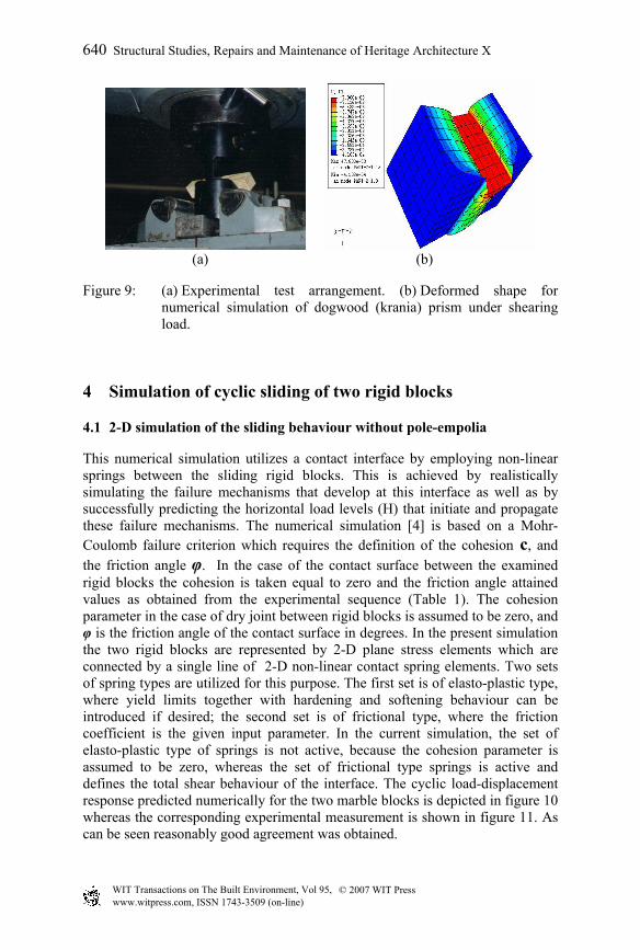
Specimens of the poles that exist as part of the connection between the examined sliding rigid bodies are loaded in shear. Simulating this shear behaviour is utilized in order to develop constitutive laws that can be included in the complex numerical simulation of sliding blocks with pole, which is presented in section 4. The distinct shear behaviour of the pole was determined by simple shearing tests of small wooden prismatic specimens (figure 9(a)) made of the same material as the actual pole used in the complex sliding tests. Figure 9(a), presents the test set-up used to determine this distinct shear behaviour of the pole. A numerical model of this shearing test is shown in figures 9(b), whereby the middle part is being sheared against the two end parts, including plastic deformations, as was done during the shear test. By comparing the numerical load-displacement curve with the corresponding experimental shearing behaviour of the pole the accuracy of this approximation was checked. Adjusting the non-linear material properties of the numerical model the agreement with the experiment could be improved up to an acceptable level. In this way the pole non-linear material properties were obtained to be utilized in the sliding simulation of rigid block with pole-empolia.
Structural Studies, Repairs and Maintenance of Heritage Architecture X 639
© 2007 WIT PressWIT Transactions on The Built Environment, Vol 95, www.witpress.com, ISSN 1743-3509 (on-line)
(a) (b)
Figure 9: (a) Experimental test arrangement. (b) Deformed shape for numerical simulation of dogwood (krania) prism under shearing load.
4 Simulation of cyclic sliding of two rigid blocks
4.1 2-D simulation of the sliding behaviour without pole-empolia
This numerical simulation utilizes a contact interface by employing non-linear springs between the sliding rigid blocks. This is achieved by realistically simulating the failure mechanisms that develop at this interface as well as by successfully predicting the horizontal load levels (H) that initiate and propagate these failure mechanisms. The numerical simulation [4] is based on a Mohr-Coulomb failure criterion which requires the definition of the cohesion c, and the friction angle φ. In the case of the contact surface between the examined rigid blocks the cohesion is taken equal to zero and the friction angle attained values as obtained from the experimental sequence (Table 1). The cohesion parameter in the case of dry joint between rigid blocks is assumed to be zero, and φ is the friction angle of the contact surface in degrees. In the present simulation the two rigid blocks are represented by 2-D plane stress elements which are connected by a single line of 2-D non-linear contact spring elements. Two sets of spring types are utilized for this purpose. The first set is of elasto-plastic type, where yield limits together with hardening and softening behaviour can be introduced if desired; the second set is of frictional type, where the friction coefficient is the given input parameter. In the current simulation, the set of elasto-plastic type of springs is not active, because the cohesion parameter is assumed to be zero, whereas the set of frictional type springs is active and defines the total shear behaviour of the interface. The cyclic load-displacement response predicted numerically for the two marble blocks is depicted in figure 10 whereas the corresponding experimental measurement is shown in figure 11. As can be seen reasonably good agreement was obtained.
640 Structural Studies, Repairs and Maintenance of Heritage Architecture X
© 2007 WIT PressWIT Transactions on The Built Environment, Vol 95, www.witpress.com, ISSN 1743-3509 (on-line)

Figure 10: Numerical sliding response for marble blocks with normal stress 0.125Mpa, without pole-empolio.
Figure 11: Experimental sliding response for marble blocks with normal stress 0.125Mpa, without pole-empolio.
4.2 3-D simulation of two rigid blocks sliding including pole-empolia
This time, the objective of the numerical investigation was to model the sliding behaviour of two rigid bodies including a connection with pole and empolia approximated by 3-D simulations depicted in figure 12(a,b). Three dimensional finite elements were utilized to simulate the rigid bodies assuming that they remain elastic throughout the loading sequence. The empolia and the pole are modeled as three dimensional elements with the capability of performing non-linearly, being assigned mechanical properties which were obtained from the numerical simulations described in paragraphs 3.1 and 3.2. The friction between the two sliding bodies was also modeled, adopting values of friction angle measured during the experiments (section 4.1). The cyclic load-displacement response predicted numerically for steel blocks with dogwood (krania) pole and lead empolio, when connecting rigid bodies with either frictional or frictionless surfaces between the blocks, is depicted in figures 13(a) and 13(b), respectively.
(a) (b)
Figure 12: (a) 3-D representation of two rigid blocks, (b) 3-D representation of the pole-empolia at the sliding surface.
Structural Studies, Repairs and Maintenance of Heritage Architecture X 641
© 2007 WIT PressWIT Transactions on The Built Environment, Vol 95, www.witpress.com, ISSN 1743-3509 (on-line)

(a) (b)
Figure 13: (a) Total load-displacement response for steel blocks with empolia and pole (both the blocks and the pole-empolia), (b) load-displacement response for steel blocks with empolia and pole (frictionless surface).
(a) (b)
Figure 14: (a) 3-D simulation of pole-empolio within the two rigid blocks, (b) plastic deformations predicted for the pole-empolia.
The cyclic load-displacement response observed experimentally was already depicted in figures 5 and 6 for the marble contact surface, without or with pole-empolia connection, respectively. As can be seen the observed influence of the pole-empolia connection is reproduced numerically. Moreover, the 3-D numerical simulation of the pole-empolia (figure 14(a)) predicts plastic deformations for the pole-empolia connection which is depicted in figure 14(b). This is a realistic representation of the observed permanent deformations at the end of each test sequence, which are not presented here due to lack of space.
5 Conclusions
The comparison of experimental and numerical results demonstrate the following: - The friction mechanism between rigid bodies was simulated reasonably well
by the proposed simulation.
642 Structural Studies, Repairs and Maintenance of Heritage Architecture X
© 2007 WIT PressWIT Transactions on The Built Environment, Vol 95, www.witpress.com, ISSN 1743-3509 (on-line)
- The separate simple numerical simulation of either the penetration of a pole into a media (empolia) with plastic deformations or of the shearing of a pole were quite successful, when compared with the corresponding observations; these preliminary simulations provided the basis for the most complex sliding behaviour of two rigid blocks with a pole-empolia connection.
- The 3-D employed numerical simulation of the sliding behaviour of two rigid bodies under shear, with and without the pole-empolia connection, can successfully predict the measured strength during the experimental sequence.
- The introduction of poles and empolia can increase the shear resistance of rigid bodies. This increase depends on the dimensions of the parts of this connection and on their mechanical properties.
- The presented numerical simulation can be further utilised to investigate the shear behaviour of prototype sections of ancient monuments.
References
[1] G.C Manos , M. Demosthenous “Study of the dynamic response of models of ancient columns or colonnades subjected to horizontal base motions”, 11 WCEE, Session 6.3.3 of Abstract Volume Analysis of Masonry Structures, Acapulco, Mexico, 1996.
[2] G.C Manos, M. Demosthenous “The dynamic response of a simple rigid formation including two rigid columns and a top rigid block”, 14th SMIRT, Volume K part, pp 399-406, Lyon, France, 1997.
[3] G.C Manos, M. Demosthenous, V. Kourtides, “The Dynamic and Earthquake Behavior of Ancient Columns and Colonnades with and without Energy Dissipation Devices”, 12th European Earthquake Engineering Conference, London, England, 2002.
[4] P.B. Lourenco, L.F. Ramos, “Characterization of Cyclic Behaviour of Dry Masonry Joint” Rep. Praxis-C-ECM-13247-1998, Univ. of Minho, Portugal.
[5] P.B.Lourenco, “Computational Strategies for Masonry Structures”, Thesis Delft University Press, Netherlands, 1997.
[6] Abacus version 6.5, Theory Manual, 2003. [7] Lusas version 13.6, Theory Manual, 2005.
Structural Studies, Repairs and Maintenance of Heritage Architecture X 643
© 2007 WIT PressWIT Transactions on The Built Environment, Vol 95, www.witpress.com, ISSN 1743-3509 (on-line)