EXPERIMENTAL AND NUMERICAL INVESTIGATION OF RESONATOR ... · EXPERIMENTAL AND NUMERICAL...
8
EXPERIMENTAL AND NUMERICAL INVESTIGATION OF RESONATOR BASED ACOUSTIC DAMPING Felix Grimm, Michael Stöhr, Berthold Noll, Manfred Aigner German Aerospace Center (DLR) - Institute of Combustion Technology, Stuttgart, Germany email: [email protected] Jürgen Dierke, Roland Ewert German Aerospace Center (DLR) - Institute of Aerodynamics and Flow Technology, Braunschweig, Germany Combustion induced noise and thermoacoustic limit cycle phenomena significantly contribute to engine noise levels in civil aviation. Therefore, the development of reliable noise reduction strate- gies is a prevailing research field. In the presented paper, resonator based damping panels are experimentally and numerically investigated. The TNF standard DLR-A jet flame is studied with encasement and damping panels. Those acoustic liners are designed as an array of Helmholtz resonator similar elements. Therefore, a design strategy derived from a mechanical spring-mass- damper analogy is used. Frequency dependent impedance functions are evaluated with geomet- rical parameters of the acoustic liner. Three different configurations are tested for the damping panels: Sound hard walls, damping of the first acoustic longitudinal mode and the first acousti- cally stable transverse mode in the flame tube. Experimental results are compared to numerical simulations with the Fast Random Particle Method for Combustion Noise Prediction (FRPM-CN). The approach relies on stochastic, particle based sound source reconstruction with turbulence statistics from CFD calculations. Sound propaga- tion is computed via linearized Euler equations. Damping panels are simulated with an Extended Helmholtz Resonator (EHR) model, implemented in the PIANO research code. Keywords: CFD, Computational Combustion Acoustics (CCA), FRPM-CN, EHR, Helmholtz- Resonator. 1. Introduction Combustion noise and thermoacoustic instabilities are an increasingly important issue in modern, lean-premixed aero-engines and gas turbines. Especially in the field of aviation, noise emissions have become a widely recognized and investigated problem, due to more and more strict emissions regu- lations. The development of reliable noise and pressure oscillation damping techniques is therefore a highly relevant, topical research field. In the presented paper, resonator based damping mechanisms of resonance phenomena are addressed numerically and experimentally. A key issue of the presented study is the theoretical assessment of damping mechanisms. In principle, there are two possibilities for the modelling of damping elements in time-domain [1]. A wide-spread method is the formulation of frequency-dependent multi-pole boundary conditions, where any cus- tomized impedance characteristics can be imposed [2], without the need for a direct depiction of physical effects. As a downside of this variant, impedance characteristics have to be known a priori from measurements. The second possibility is the direct modeling of physical effects via e.g. sim- ple mass-spring-damper analogies, where damping characteristics can be determined based on only 1
Transcript of EXPERIMENTAL AND NUMERICAL INVESTIGATION OF RESONATOR ... · EXPERIMENTAL AND NUMERICAL...
EXPERIMENTAL AND NUMERICAL INVESTIGATION OFRESONATOR BASED ACOUSTIC DAMPING
Felix Grimm, Michael Stöhr, Berthold Noll, Manfred AignerGerman Aerospace Center (DLR) - Institute of Combustion Technology, Stuttgart, Germany
email: [email protected]
Jürgen Dierke, Roland EwertGerman Aerospace Center (DLR) - Institute of Aerodynamics and Flow Technology, Braunschweig, Germany
Combustion induced noise and thermoacoustic limit cycle phenomena significantly contribute to
engine noise levels in civil aviation. Therefore, the development of reliable noise reduction strate-
gies is a prevailing research field. In the presented paper, resonator based damping panels are
experimentally and numerically investigated. The TNF standard DLR-A jet flame is studied with
encasement and damping panels. Those acoustic liners are designed as an array of Helmholtz
resonator similar elements. Therefore, a design strategy derived from a mechanical spring-mass-
damper analogy is used. Frequency dependent impedance functions are evaluated with geomet-
rical parameters of the acoustic liner. Three different configurations are tested for the damping
panels: Sound hard walls, damping of the first acoustic longitudinal mode and the first acousti-
cally stable transverse mode in the flame tube.
Experimental results are compared to numerical simulations with the Fast Random Particle Method
for Combustion Noise Prediction (FRPM-CN). The approach relies on stochastic, particle based
sound source reconstruction with turbulence statistics from CFD calculations. Sound propaga-
tion is computed via linearized Euler equations. Damping panels are simulated with an Extended
Helmholtz Resonator (EHR) model, implemented in the PIANO research code.
Keywords: CFD, Computational Combustion Acoustics (CCA), FRPM-CN, EHR, Helmholtz-
Resonator.
1. Introduction
Combustion noise and thermoacoustic instabilities are an increasingly important issue in modern,
lean-premixed aero-engines and gas turbines. Especially in the field of aviation, noise emissions have
become a widely recognized and investigated problem, due to more and more strict emissions regu-
lations. The development of reliable noise and pressure oscillation damping techniques is therefore a
highly relevant, topical research field. In the presented paper, resonator based damping mechanisms
of resonance phenomena are addressed numerically and experimentally.
A key issue of the presented study is the theoretical assessment of damping mechanisms. In principle,
there are two possibilities for the modelling of damping elements in time-domain [1]. A wide-spread
method is the formulation of frequency-dependent multi-pole boundary conditions, where any cus-
tomized impedance characteristics can be imposed [2], without the need for a direct depiction of
physical effects. As a downside of this variant, impedance characteristics have to be known a priori
from measurements. The second possibility is the direct modeling of physical effects via e.g. sim-
ple mass-spring-damper analogies, where damping characteristics can be determined based on only
1
ICSV24, London, 23-27 July 2017
few system parameters [3]. In this approach, the design of damping panels can be carried out based
on fluid medium characteristics and geometric specifications of the resonators. On the other hand,
relatively small time-steps have to be chosen for stability and modeling reasons. In fundamental
investigations it can be nonetheless advantageous to choose a simplified representation of damping
panels with all the same incorporation of physical mechanisms, in order to gain a more detailed un-
derstanding of damping processes. In the presented work therefore a physically motivated model is
chosen.
The paper is structured as follows: First it is shown that the hybrid method FRPM-CN efficiently and
reliably predicts resonance modes in the flame tube, not only in terms of frequency, but also for sound
pressure amplitudes. Then, a design procedure for the EHR approach based on geometrical parame-
ters of the liner configurations is used. Subsequently, parametric studies are carried out, identifying
the impact of different damping system components like resonator volume, viscous damping, or flow
resistance on resulting sound pressure spectra. Based on this, an optimized simulation with the EHR
model is compared to the measured damping configurations. It is shown that FRPM-CN in combina-
tion with the EHR approach accurately reproduces damping effects of the presented experiment.
2. The Extended Helmholtz Resonator (EHR) Model
Impedance as an aggregation of acoustic damping mechanisms has complex valued properties. It
can be described by the simple relation
Z(iω) = X(ω) + iY (ω). (1)
The real part of Z, X , is called resistance, while the imaginary fraction Y stands for reactance [4].
ω = 2πf is the angular frequency. Acoustic resistance describes energy transfer between acoustic
waves and the surrounding media, mainly by a turnover of heat. Reactance comprises phenomena
of momentum exchange and elasticity. For the frequency dependent description of damping device
characteristics, coefficients for absorption and reflection are employed, evaluated by
αZ(ω) = 1− |RZ(ω)|2 = 1−∣
∣
∣
∣
Z(ω)− Z0
Z(ω) + Z0
∣
∣
∣
∣
2
, (2)
with the sound impulse impedance Z0 = ρ0c0, where ρ0 and c0 are density and speed of sound of the
fluid medium.
For the numerical simulations realizing frequency dependent impedance like in Eq. (1) for damping
devices, an Extended Helmholtz Resonator (EHR) model as introduced by Rienstra [3] is employed
in this work. We make us of an implementation in the PIANO research code from Bassetti et al.
[5, 6] with the theoretical description of the model from Richter et al. [7, 8]. It is used in combination
with 2D FRPM-CN, the Fast Random Particle Method for Combustion Noise prediction [9]. The EHR
model was derived based on an analogy to a mechanical spring-mass-damper system, as schematically
shown in Fig. 1. In general, frequency dependent impedance of such a spring-mass-damper system
can be generally expressed by
Z(iω) =p
un
= iωmm + d+kmiω
, (3)
with the area related quantities mm, km and d for element mass Mm, spring constant Km and damping
devices D in Fig. 1. p and un are harmonized pressure and sound speed. The equivalent to the
mechanical system is the so called Helmholtz resonator, as sketched in Fig. 1 (right). Extensive
theoretical background and description can be found in the literature [10, 8]. In practical applications,
damping devices consist of multiple Helmholtz resonators aligned in arrays. The design strategy for
such panels [11] often makes use of the ratio of active or effective area (open area) to overall panel
2 ICSV24, London, 23-27 July 2017
ICSV24, London, 23-27 July 2017
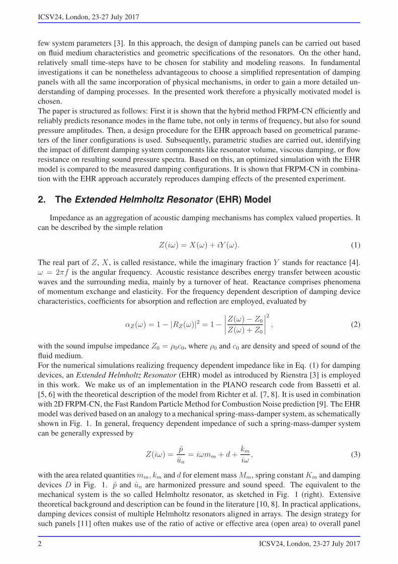
Figure 1: Mechanical spring-mass-damper analogy (left) and Helmholtz resonator (right) [8].
area, the so called porosity σ = S0/S. As a consequence, resonator frequency, mass and damping
constant amount to
mm =ρ0L
σand km =
Sρ0c2
Vand ω0 =
√
σSc2
V L. (4)
Corresponding geometrical quantities are given according to Fig. 1. S0 is the neck hole cross-section
of the resonator neck, L denotes the length of the resonator, while V are the cavity volume and ρ0 the
fluid density in the device. The frequency dependent impedance of the EHR model is [8]
ZEHR(iω) = iωmf +Rf − iβ cot
(
ωTl
2− i
ǫ
2
)
. (5)
Rf represents the real-valued resistance of the front plate with viscous and vortex-induced effects.
mf symbolizes mass inertia in resonator neck and volume. β denotes a reactance parameter in the
resonator cavity. Tl describes a time-delay induced by the panel geometry and abstracts essentially
the dynamic behavior of sound waves on their way through the resonator. ǫ stands for damping of the
fluid in the cavity. The PIANO code works in time-domain and therefore a corresponding formulation
of the model is implemented as [5, 6]
p′(t)− e−ǫ(t− Tl) = (Rf + β)u′
n(t)− (Rf − β)e−ǫ · u′
n(t− Tl)+
+mf
(
∂u′
n(t)
∂t− e−ǫ∂u
′
n(t)
∂t(t− Tl)
)
.(6)
3. Resonator array design and experimental setup
The impedance characteristics of the damping panels are designed with the relation [12, 13]
ZLiner(iω) = R + iωm+ρc2
iωd. (7)
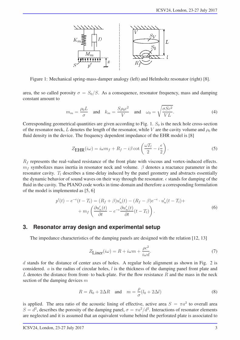
d stands for the distance of center axes of holes. A regular hole alignment as shown in Fig. 2 is
considered. a is the radius of circular holes, l is the thickness of the damping panel front plate and
L denotes the distance from front- to back-plate. For the flow resistance R and the mass in the neck
section of the damping devices m
R = R0 + 2∆R and m =ρ
σ(l0 + 2∆l) (8)
is applied. The area ratio of the acoustic lining of effective, active area S = πa2 to overall area
S = d2, describes the porosity of the damping panel, σ = πa2/d2. Interactions of resonator elements
are neglected and it is assumed that an equivalent volume behind the perforated plate is associated to
ICSV24, London, 23-27 July 2017 3
ICSV24, London, 23-27 July 2017
Figure 2: Schematic drawing of measured damping panel and area ratio of perforated and back plate
[12].
each resonator element, as indicated in Fig. 2. A correction for the oscillating mass in the resonator
necks is applied [14, 12],
∆l = 0.8a(1− 1.4√σ). (9)
Equation (9) takes into account the interaction of the single holes in the range of σ ≤ 0.2. The flow
resistance R in Eq. (8) contains a fraction for the viscous resistance in the resonator neck R0 and the
viscous resistance at hole edges via motion of the fluid medium 2∆R in the regions outside of the
neck. Whether the neck area is narrow or wide in terms of viscous damping, a so called viscous wave
length [12] λη = 0.0137/√f [m] is defined. This criterion is explicitly applied for each frequency
in the resonator design process. Above a threshold value a ≥ 0.63λη, a wide opening is defined and
below the value, a narrow opening is considered,
R0,W = 0.53 · 10−2d2l
a3
√
f
[
Ns
m3
]
or R0,N = 0.46 · 10−4d2l
a4
[
Ns
m3
]
. (10)
In both cases, the correction 2∆R is evaluated with
2∆R = 1.05 · 10−2d2
a2
√
f
[
Ns
m3
]
. (11)
The experimental setting is shown in Fig. 3. Two different damping configurations are tested, lined
walls with resonator elements and lined walls without back plate (L → ∞). Accompanying this,
pressure spectra for sound hard walls are measured, as in preceding studies [15]. In the case of lined
walls, a constant radial distance between perforate and solid wall is ensured via set screws. For manu-
facturing reasons, perforated walls are commercially available plates, therefore the design parameters
of plate thickness l, hole distance d and hole radius a are strongly limited. The parameter to be mainly
varied in relevant regions is the radial length L, determining the resonator volumes. It is however lim-
ited through the assumption of a locally plane damping panel, which is implied in the design process
as previously introduced. It can be shown with parametric studies that an increase in resonator volume
by increasing L, lower frequencies are damped. For the design point f2 = 1600Hz, as shown in Fig.
3, the parameters L = 0.0065m, l = 0.002m, a = 0.00225m, d = 0.025m and σ = 0.03 are realized
in experiments and L → ∞ for the treatment of f2 = 260Hz. The panel design procedure is carried
out for ambient air conditions.
The flame tube has an inner diameter of 37.5d/D and a length of 62.5y/D and is mounted to a hor-
izontally aligned base plate. Acoustic pressure recorders are mounted concisely with the perforated
wall with positions as shown in Fig. 3. The upstream fuel inlet tube has the diameter D = 0.008m,
which is used for referencing purposes and a length of 43.75y/D. Brül& Kjaer type 4939 micro-
phones are used with a type 2670 preamplifier. Measurements are carried out at p∞ = 957.7hPa.
Time samples are collected with a sampling rate of 200kHz, while resulting pressure spectra are eval-
uated over a time span of 60s and a narrow band spectrum with ∆f = 1Hz is evaluated.
4 ICSV24, London, 23-27 July 2017
ICSV24, London, 23-27 July 2017
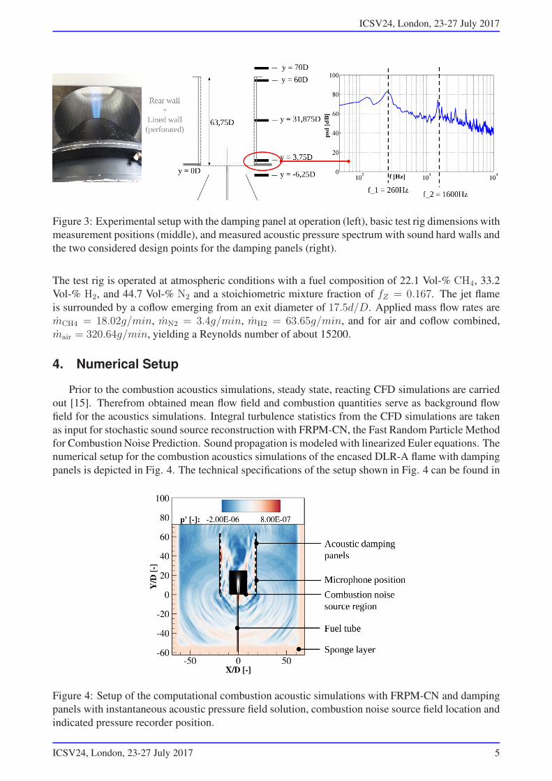
Figure 3: Experimental setup with the damping panel at operation (left), basic test rig dimensions with
measurement positions (middle), and measured acoustic pressure spectrum with sound hard walls and
the two considered design points for the damping panels (right).
The test rig is operated at atmospheric conditions with a fuel composition of 22.1 Vol-% CH4, 33.2
Vol-% H2, and 44.7 Vol-% N2 and a stoichiometric mixture fraction of fZ = 0.167. The jet flame
is surrounded by a coflow emerging from an exit diameter of 17.5d/D. Applied mass flow rates are
mCH4 = 18.02g/min, mN2 = 3.4g/min, mH2 = 63.65g/min, and for air and coflow combined,
mair = 320.64g/min, yielding a Reynolds number of about 15200.
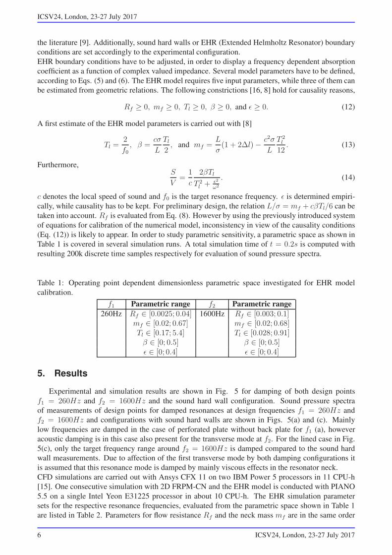
4. Numerical Setup
Prior to the combustion acoustics simulations, steady state, reacting CFD simulations are carried
out [15]. Therefrom obtained mean flow field and combustion quantities serve as background flow
field for the acoustics simulations. Integral turbulence statistics from the CFD simulations are taken
as input for stochastic sound source reconstruction with FRPM-CN, the Fast Random Particle Method
for Combustion Noise Prediction. Sound propagation is modeled with linearized Euler equations. The
numerical setup for the combustion acoustics simulations of the encased DLR-A flame with damping
panels is depicted in Fig. 4. The technical specifications of the setup shown in Fig. 4 can be found in
Figure 4: Setup of the computational combustion acoustic simulations with FRPM-CN and damping
panels with instantaneous acoustic pressure field solution, combustion noise source field location and
indicated pressure recorder position.
ICSV24, London, 23-27 July 2017 5
ICSV24, London, 23-27 July 2017
the literature [9]. Additionally, sound hard walls or EHR (Extended Helmholtz Resonator) boundary
conditions are set accordingly to the experimental configuration.
EHR boundary conditions have to be adjusted, in order to display a frequency dependent absorption
coefficient as a function of complex valued impedance. Several model parameters have to be defined,
according to Eqs. (5) and (6). The EHR model requires five input parameters, while three of them can
be estimated from geometric relations. The following constrictions [16, 8] hold for causality reasons,
Rf ≥ 0, mf ≥ 0, Tl ≥ 0, β ≥ 0, and ǫ ≥ 0. (12)
A first estimate of the EHR model parameters is carried out with [8]
Tl =2
f0, β =
cσ
L
Tl
2, and mf =
L
σ(1 + 2∆l)− c2σ
L
T 2
l
12. (13)
Furthermore,S
V=
1
c
2βTl
T 2
l + ǫ2
ω2
. (14)
c denotes the local speed of sound and f0 is the target resonance frequency. ǫ is determined empiri-
cally, while causality has to be kept. For preliminary design, the relation L/σ = mf + cβTl/6 can be
taken into account. Rf is evaluated from Eq. (8). However by using the previously introduced system
of equations for calibration of the numerical model, inconsistency in view of the causality conditions
(Eq. (12)) is likely to appear. In order to study parametric sensitivity, a parametric space as shown in
Table 1 is covered in several simulation runs. A total simulation time of t = 0.2s is computed with
resulting 200k discrete time samples respectively for evaluation of sound pressure spectra.
Table 1: Operating point dependent dimensionless parametric space investigated for EHR model
calibration.
f1 Parametric range f2 Parametric range
260Hz Rf ∈ [0.0025; 0.04] 1600Hz Rf ∈ [0.003; 0.1]mf ∈ [0.02; 0.67] mf ∈ [0.02; 0.68]Tl ∈ [0.17; 5.4] Tl ∈ [0.028; 0.91]β ∈ [0; 0.5] β ∈ [0; 0.5]ǫ ∈ [0; 0.4] ǫ ∈ [0; 0.4]
5. Results
Experimental and simulation results are shown in Fig. 5 for damping of both design points
f1 = 260Hz and f2 = 1600Hz and the sound hard wall configuration. Sound pressure spectra
of measurements of design points for damped resonances at design frequencies f1 = 260Hz and
f2 = 1600Hz and configurations with sound hard walls are shown in Figs. 5(a) and (c). Mainly
low frequencies are damped in the case of perforated plate without back plate for f1 (a), however
acoustic damping is in this case also present for the transverse mode at f2. For the lined case in Fig.
5(c), only the target frequency range around f2 = 1600Hz is damped compared to the sound hard
wall measurements. Due to affection of the first transverse mode by both damping configurations it
is assumed that this resonance mode is damped by mainly viscous effects in the resonator neck.
CFD simulations are carried out with Ansys CFX 11 on two IBM Power 5 processors in 11 CPU-h
[15]. One consecutive simulation with 2D FRPM-CN and the EHR model is conducted with PIANO
5.5 on a single Intel Yeon E31225 processor in about 10 CPU-h. The EHR simulation parameter
sets for the respective resonance frequencies, evaluated from the parametric space shown in Table 1
are listed in Table 2. Parameters for flow resistance Rf and the neck mass mf are in the same order
6 ICSV24, London, 23-27 July 2017
ICSV24, London, 23-27 July 2017
f [Hz]102
103
104
psd
[dB
]
0
20
40
60
80
100
Experiment, undamped
Experiment, damped
(a) Experiment, perforated plate, f1 = 260Hz.
f [Hz]102
103
104
psd
[dB
]
2D FRPM-CN, undamped
2D FRPM-CN, EHR20 dB
(b) Simulation, perforated plate, f1 = 260Hz.
f [Hz]102
103
104
psd
[dB
]
0
20
40
60
80
100
Experiment, undamped
Experiment, damped
(c) Experiment, lined walls, f2 = 1600Hz.
f [Hz]102
103
104
psd
[dB
]
2D FRPM-CN, undamped
2D FRPM-CN, EHR20 dB
(d) Simulation, lined walls, f2 = 1600Hz.
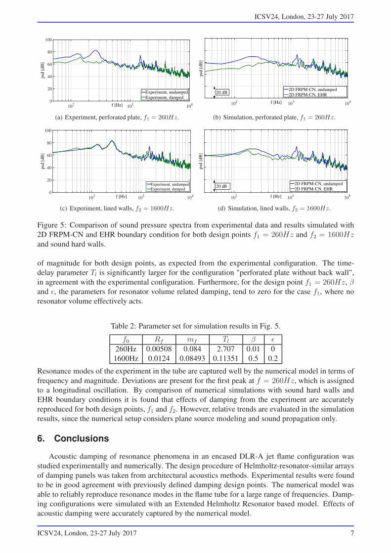
Figure 5: Comparison of sound pressure spectra from experimental data and results simulated with
2D FRPM-CN and EHR boundary condition for both design points f1 = 260Hz and f2 = 1600Hzand sound hard walls.
of magnitude for both design points, as expected from the experimental configuration. The time-
delay parameter Tl is significantly larger for the configuration "perforated plate without back wall",
in agreement with the experimental configuration. Furthermore, for the design point f1 = 260Hz, βand ǫ, the parameters for resonator volume related damping, tend to zero for the case f1, where no
resonator volume effectively acts.
Table 2: Parameter set for simulation results in Fig. 5.
f0 Rf mf Tl β ǫ260Hz 0.00508 0.084 2.707 0.01 0
1600Hz 0.0124 0.08493 0.11351 0.5 0.2
Resonance modes of the experiment in the tube are captured well by the numerical model in terms of
frequency and magnitude. Deviations are present for the first peak at f = 260Hz, which is assigned
to a longitudinal oscillation. By comparison of numerical simulations with sound hard walls and
EHR boundary conditions it is found that effects of damping from the experiment are accurately
reproduced for both design points, f1 and f2. However, relative trends are evaluated in the simulation
results, since the numerical setup considers plane source modeling and sound propagation only.
6. Conclusions
Acoustic damping of resonance phenomena in an encased DLR-A jet flame configuration was
studied experimentally and numerically. The design procedure of Helmholtz-resonator-similar arrays
of damping panels was taken from architectural acoustics methods. Experimental results were found
to be in good agreement with previously defined damping design points. The numerical model was
able to reliably reproduce resonance modes in the flame tube for a large range of frequencies. Damp-
ing configurations were simulated with an Extended Helmholtz Resonator based model. Effects of
acoustic damping were accurately captured by the numerical model.
ICSV24, London, 23-27 July 2017 7
ICSV24, London, 23-27 July 2017
Acknowledgments
This collaborative work was supported within the project DECISIVE which was funded by the
German Aerospace Center (DLR).
References
1. Richter, C. A review of time domain impedance boundary conditions. societe francaise d’acoustique.,
Proceedings of the Acoustics 2012 Nantes Conference, nantes, France. hal-00810672, (2012).
2. Lourier, J.-M., Noll, B. and Aigner, M. Large eddy simulation of a thermoacoustic instability within a
swirl-stabilized burner using impedance boundary conditions, Proceedings of ASME Turbo Expo 2014,
gT2014-26200, (2014).
3. Rienstra, S. Impedance models in time domain including the extended helmholtz resonator model, 12th
AIAA/CEAS Aeroacoustics Conference, Cambridge, MA, USA, (2006).
4. Bellucci, V., Flohr, P. and Paschereit, C. Numerical and experimental study of acoustic damping generated
by perforated screens, AIAA Journal, 42 (8), 1543–1549, (2004).
5. Bassetti, A., Guerin, S. and Kornow, O. Introducing lined-wall boundary conditions in the dlr time-domain
caa solver piano, DAGA Conference, paper no. 160, (2010).
6. Bassetti, A., Guerin, S. and Busse, S. Validation of the caa solver piano with lined-wall boundary condition,
DAGA Conference, paper no. 179, (2011).
7. Richter, C., Thiele, F., Li, X. and Zhuang, M. Comparison of time-domain impedance boundary conditions
for lined duct flows, AIAA Journal, 45 (6), 1333–1345, (2007).
8. Richter, C., Liner impedance modeling in the time domain with flow, PhD Thesis, Technische Universität
Berlin, https://opus4.kobv.de/opus4-tuberlin/frontdoor/index/index/docId/2408, (2009).
9. Grimm, F., Ewert, R., Dierke, J., Noll, B. and Aigner, M. The fast random particle method for combustion
noise prediction, 20th AIAA/CEAS Aeroacoustics Conference, aIAA Paper 2014-2451, (2014).
10. Ehrenfried, K., Strömungsakustik, Mensch und Buch Verlag AG, Berlin, ISBN 3-89820-699-8 (2004).
11. Fuchs, H., Schallabsorber und Schalldämpfer, Springer, Berlin, Heidelberg, ISBN 3-540-35493-X (2004).
12. Bräuer, J. and Weselak, W. Lochplatten-, schlitzplatten- und helmholtz-absorber, Projektarbeit, Instistut
für Breitbandkommunikation, TU Graz, (2010).
13. Maa, D.-Y. Theory and design of microperforated panel sound absorbing constructions (chinesisch), Sci-
entia Sinica, 18, 55–71, (1975).
14. Ingard, U. On the theory and design of acoustic resonators, J. Acoust. Soc. Am., 25, 1037, (1953).
15. Mühlbauer, B., Stöhr, M., Noll, B. and Aigner, M. Broadband Combustion Noise Measurements and
Numerical Simulation of Enclosed Turbulent Non-Premixed Jet Flames, 18th International Congress on
Sound and Vibration, rio de Janeiro, Brazil, (2011).
16. Chevaugeon, N., Remacle, J.-F. and Gallez, X. Discontinuous galerkin implementation of the extended
helmholtz resonator model in time domain, 12th AIAA/CEAS Aeroacoustics Conference (27th Aeroacous-
tics Conference), aIAA 2006-2569, (2006).
8 ICSV24, London, 23-27 July 2017