Experimental and Numerical Determination of ...alexeenk/papers/aiaaj-05.pdf · Experimental and...
10
P1: FHK/KXI P2: ILT/UBM/ILT AIAA [aiaaj] 15:33 22 November 2004 AI378F-03/J27142(A)/Ketsdever AIAA JOURNAL Vol. 43, No. 1, January 2005 (Tentative) Experimental and Numerical Determination of Micropropulsion Device Efficiencies at Low Reynolds Numbers Andrew D. Ketsdever ∗ U.S. Air Force Research Laboratory, Edwards Air Force Base, California 93524 and Michael T. Clabough, † Sergey F. Gimelshein, ‡ and Alina Alexeenko § University of Southern California, Los Angeles, California 90089-1191 The need for low-thrust propulsion systems for maneuvers on micro- and nanospacecraft is growing. Low-thrust characteristics generally lead to low-Reynolds-number flows from propulsive devices that utilize nozzle expansions. Low-Reynolds-number flows of helium and nitrogen through a small conical nozzle and a thin-walled orifice have been investigated both numerically, using the direct simulation Monte Carlo technique, and experimentally, using a nano-Newton thrust stand. For throat Reynolds number less than 100, the nozzle-to-orifice thrust ratio is less than unity; however, the corresponding ratio of specific impulse remains greater than one for the Reynolds number range from 0.02 to 200. Once the direct simulation Monte Carlo model results were verified using experimental thrust and mass flow data, the model was used to investigate the effects of geometrical variations on the conical nozzle’s performance. At low Reynolds numbers, improvements to the specific impulse on the order of 4 to 8% were achieved through a combination of decreasing the nozzle length and increasing the nozzle expansion angle relative to the nominal experimental geometry. Nomenclature A = area, m 2 d = diameter, m Isp = specific impulse, s k = Boltzmann’s constant, = 1.3806503 × 10 −23 J/K L = nominal length of the diverging section of the nozzle, m l w = nominal length of the diverging section wall of the nozzle, m M = Mach number m = molecular mass, kg n = unit vector normal to a surface p = pressure, Pa Re = Reynolds number T = temperature, K = thrust, N t = orifice thickness, m u = axial velocity, m/s v = radial velocity component, m/s v = velocity vector α = fraction of molecules reflected diffusely from a surface γ = ratio of specific heats θ = divergent half-angle of the nozzle µ = viscosity, kg/m 2 s ρ = density, kg/m 3 Received 20 April 2004; revision received 22 September 2004; accepted for publication 2 October 2004. This material is declared a work of the U.S. Government and is not subject to copyright protection in the United States. Copies of this paper may be made for personal or internal use, on condition that the copier pay the $10.00 per-copy fee to the Copyright Clearance Center, Inc., 222 Rosewood Drive, Danvers, MA 01923; include the code 0001-1452/05 $10.00 in correspondence with the CCC. ∗ Group Leader, Aerophysics Branch, Propulsion Directorate, 10 E. Saturn Boulevard; [email protected]. Senior Member AIAA. † Graduate Research Assistant, Department of Aerospace and Mechanical Engineering. ‡ Research Professor, Department of Aerospace and Mechanical Engineer- ing, 854 W. 36th Place; [email protected]. Member AIAA. § WISE Postdoctoral Fellow, Department of Aerospace and Mechanical Engineering; [email protected]. Member AIAA. τ = unit vector tangential to a surface ω = viscosity exponent Subscripts c = curvature cont = continuum e = exit condition fm = free molecular n = nozzle o = orifice ref = reference value t = throat condition w = wall x = axial component η = value normal to a surface τ = value tangential to a surface 0 = plenum or stagnation Superscripts - = mean value = after collision value ∗ = sonic condition Introduction F UTURE micro- and nanosatellites will require low-thrust propulsion systems for orbital maneuvers to counter the effects of trajectory perturbations and for fine attitude control. Micropropul- sion systems for these vehicles are expected to have thrust in the range from 1 µN to 1 mN. For propulsion systems that utilize noz- zle expansions, the low thrust levels will require either low-pressure operation or a decrease in the throat dimensions, both potentially leading to low-Reynolds-number flows. The further development of efficient microchemical and electrothermal thrusters is associ- ated with high stagnation chamber temperatures, which will also continue the trend toward decreasing the Reynolds number. There- fore, the numerical and experimental investigation of low-Reynolds- number flows has become increasingly important for designing ef- ficient, low-thrust nozzles. It is well known that the Reynolds number is a measure of the noz- zle efficiency in terms of the viscous losses inherent in the subsonic layer near nozzle surfaces. At sufficiently low Reynolds numbers, 1
Transcript of Experimental and Numerical Determination of ...alexeenk/papers/aiaaj-05.pdf · Experimental and...

P1: FHK/KXI P2: ILT/UBM/ILTAIAA [aiaaj] 15:33 22 November 2004 AI378F-03/J27142(A)/Ketsdever
AIAA JOURNAL
Vol. 43, No. 1, January 2005 (Tentative)
Experimental and Numerical Determination of MicropropulsionDevice Efficiencies at Low Reynolds Numbers
Andrew D. Ketsdever∗
U.S. Air Force Research Laboratory, Edwards Air Force Base, California 93524and
Michael T. Clabough,† Sergey F. Gimelshein,‡ and Alina Alexeenko§
University of Southern California, Los Angeles, California 90089-1191
The need for low-thrust propulsion systems for maneuvers on micro- and nanospacecraft is growing. Low-thrustcharacteristics generally lead to low-Reynolds-number flows from propulsive devices that utilize nozzle expansions.Low-Reynolds-number flows of helium and nitrogen through a small conical nozzle and a thin-walled orifice havebeen investigated both numerically, using the direct simulation Monte Carlo technique, and experimentally, usinga nano-Newton thrust stand. For throat Reynolds number less than 100, the nozzle-to-orifice thrust ratio is lessthan unity; however, the corresponding ratio of specific impulse remains greater than one for the Reynolds numberrange from 0.02 to 200. Once the direct simulation Monte Carlo model results were verified using experimentalthrust and mass flow data, the model was used to investigate the effects of geometrical variations on the conicalnozzle’s performance. At low Reynolds numbers, improvements to the specific impulse on the order of 4 to 8%were achieved through a combination of decreasing the nozzle length and increasing the nozzle expansion anglerelative to the nominal experimental geometry.
NomenclatureA = area, m2
d = diameter, mIsp = specific impulse, sk = Boltzmann’s constant, = 1.3806503 × 10⁻²³ J/KL = nominal length of the diverging section
of the nozzle, mlw = nominal length of the diverging section wall
of the nozzle, mM = Mach numberm = molecular mass, kgn = unit vector normal to a surfacep = pressure, PaRe = Reynolds numberT = temperature, K� = thrust, Nt = orifice thickness, mu = axial velocity, m/sv = radial velocity component, m/sv = velocity vectorα = fraction of molecules reflected diffusely
from a surfaceγ = ratio of specific heatsθ = divergent half-angle of the nozzleµ = viscosity, kg/m2sρ = density, kg/m3
Received 20 April 2004; revision received 22 September 2004; acceptedfor publication 2 October 2004. This material is declared a work of the U.S.Government and is not subject to copyright protection in the United States.Copies of this paper may be made for personal or internal use, on conditionthat the copier pay the $10.00 per-copy fee to the Copyright ClearanceCenter, Inc., 222 Rosewood Drive, Danvers, MA 01923; include the code0001-1452/05 $10.00 in correspondence with the CCC.
∗Group Leader, Aerophysics Branch, Propulsion Directorate, 10 E. SaturnBoulevard; [email protected]. Senior Member AIAA.
†Graduate Research Assistant, Department of Aerospace and MechanicalEngineering.
‡Research Professor, Department of Aerospace and Mechanical Engineer-ing, 854 W. 36th Place; [email protected]. Member AIAA.
§WISE Postdoctoral Fellow, Department of Aerospace and MechanicalEngineering; [email protected]. Member AIAA.
τ = unit vector tangential to a surfaceω = viscosity exponent
Subscripts
c = curvaturecont = continuume = exit conditionfm = free molecularn = nozzleo = orificeref = reference valuet = throat conditionw = wallx = axial componentη = value normal to a surfaceτ = value tangential to a surface0 = plenum or stagnation
Superscripts
- = mean value′ = after collision value∗ = sonic condition
Introduction
F UTURE micro- and nanosatellites will require low-thrustpropulsion systems for orbital maneuvers to counter the effects
of trajectory perturbations and for fine attitude control. Micropropul-sion systems for these vehicles are expected to have thrust in therange from 1 µN to 1 mN. For propulsion systems that utilize noz-zle expansions, the low thrust levels will require either low-pressureoperation or a decrease in the throat dimensions, both potentiallyleading to low-Reynolds-number flows. The further developmentof efficient microchemical and electrothermal thrusters is associ-ated with high stagnation chamber temperatures, which will alsocontinue the trend toward decreasing the Reynolds number. There-fore, the numerical and experimental investigation of low-Reynolds-number flows has become increasingly important for designing ef-ficient, low-thrust nozzles.
It is well known that the Reynolds number is a measure of the noz-zle efficiency in terms of the viscous losses inherent in the subsoniclayer near nozzle surfaces. At sufficiently low Reynolds numbers,
1
P1: FHK/KXI P2: ILT/UBM/ILTAIAA [aiaaj] 15:33 22 November 2004 AI378F-03/J27142(A)/Ketsdever
2 KETSDEVER ET AL.
the viscous losses within a micronozzle become large enough for thespecific impulse along the nozzle centerline to decrease from thenozzle throat to the exit plane,1 perhaps making the divergent noz-zle contour useless. In the transitional flow regime, therefore, athin-walled sonic orifice can outperform, or at least perform as wellas, a typical micronozzle.
Although there is extensive literature related to rarefied orificeflows, there have been relatively few investigations of orifice perfor-mance in terms of propulsive parameters such as thrust and specificimpulse.2,3 Investigations of low-Reynolds-number flows throughnozzles of various geometric shapes are numerous, with several no-table computational efforts1,4−8 and experimental studies9−13 havingbeen performed. The Navier–Stokes (NS) equations with velocityslip and the direct simulation Monte Carlo (DSMC) method aretypically used to model low-Reynolds-number flows. For very lowReynolds numbers corresponding to transitional flow, reliable re-sults can only be obtained using a kinetic approach. A previousstudy has verified that the numerical results obtained with a DSMCflow solver reproduced the experimental data of Rothe,10 whereasthe solution of the NS equations with no-slip boundary conditionsdid not.1
Numerical simulations just referenced have shown that a viscouslayer occupies a significant fraction of a nozzle’s diverging sectionfor throat Reynolds numbers less than about 500. As the Reynoldsnumber further decreases, the viscous interactions dominate the in-ternal nozzle flowfield, limiting nozzle efficiency. Because an orificewith a small thickness-to-diameter ratio will have a reduced viscousinteraction layer, it can provide an adequate propulsive efficiencyrelative to a nozzle expansion at low Reynolds numbers.
The main goal of this work is to study experimentally and numer-ically the performance of a thin-walled, squared-edge orifice anda DeLaval nozzle in the transitional flow regime. The primary ob-jectives are to compare the relative performance of the nozzle andorifice geometries, find the range of Reynolds numbers where the gasexpansion through a micronozzle geometry is no longer valid froman efficiency standpoint, and investigate design parameters such asexpansion angle and length, which can improve micronozzle per-formance at low Reynolds numbers. The study also extends the lowend of the Reynolds-number range, compared to previous studies,by extending operating conditions down to the free-molecule flowregime.
Orifice and Nozzle Thrust for an Inviscid FlowTo compare micronozzle and orifice performance, as just pre-
scribed, it is advantageous to use the relative thrust or Isp ratios at aspecified pressure or throat Reynolds number. The Reynolds num-ber at a nozzle throat or a thin-walled orifice exit plane is definedas
Re∗ = ρ∗u∗dt
/µ∗ (1)
The throat density ρ∗ and the throat velocity u∗ are calculated frommeasured stagnation conditions and the quasi-one-dimensional flowrelations. The viscosity at the throat or orifice exit plane is
Q1µ∗ = ((µref{T0[2/(γ + 1)]/Tref}))ω (2)
Thruster performance is determined by considering the thrustand Isp ratio between a nozzle and a thin-walled orifice case withthe same stagnation conditions. There are two limits that need tobe considered, free-molecular and continuum. The free-moleculeanalytical solution for an infinitely thin orifice case is
�o, f m = 12 p0 Ao (3)
There is no analytical solution available for the free-molecule nozzlecase because it depends inherently on the nozzle geometry and gas-surface interactions.
Assuming there is no background pressure, the isentropic contin-uum thrust from an infinite expansion ratio nozzle is
�n, cont = γ{
[2/(γ − 1)][2/(γ + 1)](γ + 1)/(γ − 1)} 1
2 p0 At (4)
Between these two limits, the computational thrust is calculatedfor zero background pressure as
� = ρeu2e Ae = ρe
(u2
e + RTx,e
)Ae (5)
This expression is usually reduced to � = (ρeu2e + pe)Ae for finite
Reynolds numbers with supersonic conditions, which cannot beused for the nearly sonic cases considered here. Therefore, Eq. (5)is utilized for thrust calculations in this work. To calculate the thrustfrom a nozzle or orifice from Eq. (5) using a NS solver, one needsto implement the formulation of the NS equations with separatetemperature components.
Experimental SetupAll thrust measurements were performed on the nano-Newton
thrust stand (nNTS), which has been described in detail by Jamisonet al.14 The nNTS was installed in Chamber IV of the CollaborativeHigh Altitude Flow Facilities (CHAFF-IV), which is a 3-m-diam× 6-m-long cylindrical, high vacuum chamber. The facility waspumped with a 1-m-diam diffusion pump with a pumping speedof 42,000 L/s for helium and 25,000 L/s for molecular nitrogen.The ultimate facility pressure was approximately 10−6 torr with alloperational pressures below 10−4 torr. A previous study15 has shownthat at these background pressures and corresponding thrust levelsthere is no evidence of background pressure effects on the thrustmeasurements in CHAFF-IV.
The thin-walled orifice used in this study is shown schematicallyin Fig. 1. The 1-mm-diam orifice was attached to a plenum witha cross-sectional area much larger than the orifice area to help en-sure uniform flow. The orifice was machined in a 0.015-mm-thicktantalum shim giving t/d = 0.015. The thin-walled geometry waschosen to minimize the viscous effects in the orifice flow.
The conical De Laval nozzle used in this study is shown schemat-ically in Fig. 2. The conical nozzle was scaled from the geometryused by Rothe.10 The scaled Rothe geometry has a 30-deg subsonicsection, a relatively sharp 1-mm-diam throat with radius of curva-ture rc = dt/4, a 20-deg diverging section, and an expansion ratio
Fig. 1 Thin-walled orifice geometry.
Fig. 2 Experimental geometry of the conical DeLaval nozzle.

P1: FHK/KXI P2: ILT/UBM/ILTAIAA [aiaaj] 15:33 22 November 2004 AI378F-03/J27142(A)/Ketsdever
KETSDEVER ET AL. 3
Fig. 3 SEM imaging showing the surface roughness of the expanding section of the conical nozzle.
of 62.4. This geometry was selected because of the extensive ex-perimental data that exists,10 which was previously used to verifythe DSMC model’s accuracy.1 The nozzle was machined from alu-minum and attached to a cylindrical aluminum plenum and mountedon the nNTS. Figure 3 shows a scanning electron microscope imageof the nozzle side wall, where the surface features caused by the ma-chining process are clearly evident. The effect of the rough divergingsection walls on the nozzle’s performance will be investigated in thefollowing sections.
The stagnation pressures for the orifice and nozzle were measured
Q2
inside their respective plenums using calibrated pressure transduc-ers. The propellant was introduced to the plenum through an ad-justable needle valve located downstream of a mass flowmeter. Inthe experimental configuration, the mass flowmeters were operatedin the continuum regime throughout the pressure range investigated.The propellants used were molecular nitrogen and helium. In thisstudy, the stagnation pressures ranged from several millitorr to ap-proximately 17 torr for both propellants, and the stagnation tem-perature was measured to be 295 K. The combination of stagnationpressure and temperature gave maximum Reynolds numbers of 350for nitrogen and about 150 for helium.
The nNTS was calibrated using the gas dynamic and electrostaticcalibration techniques described by Selden and Ketsdever,16 whichhave been validated through experimental and numerical analysis. Aunique feature of the nNTS is its ability to measure the force levelsof the 1.0-mm orifice and nozzle geometries from the free moleculethrough continuum range. The low thrust measuring capability of thenNTS allowed for the investigation of the transitional flow regimeoverlooked in previous low-Reynolds-number nozzle studies.
Numerical MethodThe flow and geometric conditions of the experimental setup just
described were simulated and used for validation of the DSMC mod-els and parameters. All walls were assumed to be at a temperature of295 K (as measured in the experiments), and the gases consideredinclude helium and nitrogen at a stagnation temperature of 295 K. Abackground pressure of zero was assumed in the calculations. Thethroat Reynolds numbers ranged from 0.02 to 270 to adequatelycover the range of the experimental data. After the numerical modelwas analyzed, it was used to study the impact of nozzle parametersof interest. First, the half-angle of the diverging section of the nozzlewas varied from the experimental case (θ = 20 deg) to 25, 30, and40 deg while keeping the wall length lw constant. Second, the nozzle
diverging section length was then shortened from the experimentallength to L/2 and L/3.
The SMILE computational tool based on the DSMC methodwas used in the numerical part of this work. Details on the toolcan be found elsewhere.17 The SMILE capabilities that were usedin the present work include two-level rectangular grids adaptiveto flow gradients, different grids for collisions and macroparame-ters, and parallel implementation with a static load balancing tech-nique. The majorant frequency scheme was employed for model-ing molecular collisions,18 and the variable-hard-sphere model wasused for modeling intermolecular interactions. The discrete Larsen–Borgnakke model19,20 with temperature-dependent rotational relax-ation number was utilized for rotation-translation energy transfer.The Maxwell model with different values of accommodation coef-ficients was used to model gas-surface interaction. The backgroundcell size was a fraction of the mean free path at the throat conditions.Over two million simulated particles were used in the nozzle cases,and over six million particles were used in the orifice cases.
The difficulty with calculations involving subsonic boundary con-ditions is attributed to the upstream influence of the downstreamflow. To deal with these effects, results must be independent of thedomain size. For the orifice, the simulated plenum (subsonic sec-tion) was varied in the axial direction from 3dt to 9dt and in theradial direction from 4dt to 8dt with an exit plane Reynolds numberof 200 to show that the macroparameters at the exit are independentof the plenum size. The simulated plenum size was then chosen tobe 9dt × 8dt for all cases. The computational domain beyond theorifice exit plane (simulated vacuum facility domain) was varied inthe axial direction from 11dt to 15dt and in the radial direction from5dt to 30dt to show the independence of the results relative to thevacuum facility domain size. The simulated vacuum facility domainwas then chosen to be 11dt × 8dt . An equilibrium distribution withvalues of stagnation pressure and temperature and zero average ve-locity was used at the top and left boundaries of the plenum in allorifice calculations.
For the nozzle, the computational domain beyond the exit plane(exhausting into the vacuum facility) was varied in the axial direc-tion from 2dt to 20dt and in the radial direction from 1dt to 11dt
above the exit. The effect of having a larger downstream region wasexamined and determined to have negligible effect. This exit regionwas then chosen to go 2dt beyond the exit and 1dt above the exit.To study the effect of the subsonic inflow condition, computationswere performed for a plenum of 5dt × 5dt and for inflow boundarieslocated at M = 0.1 and 0.3. The effect on the nozzle thrust with a

P1: FHK/KXI P2: ILT/UBM/ILTAIAA [aiaaj] 15:33 22 November 2004 AI378F-03/J27142(A)/Ketsdever
4 KETSDEVER ET AL.
throat Reynolds number of 200 was found to be negligible. Thecomputed thrust for Re∗ = 60 was found to be up to 3% differentfor the subsonic boundaries located at M = 0.1 and 0.3 comparedto thrust computed with the plenum domain included. The differ-ence was caused by the impact of the viscous interaction layer inthe converging section. Therefore, the plenum geometry was usedthroughout the remainder of this study, and the plenum dimensionsremained constant for all subsequent simulations.
Results and DiscussionOrifice and Nozzle Flow Structure
First, the flow structure for the two geometries under considera-tion with different gas densities, or Reynolds numbers, is examinednumerically. Note that the results in this section are shown for he-lium flows only because the general flow structure for nitrogen isqualitatively similar for the same Reynolds number. The predictedMach-number contours for the orifice geometry with Re∗ = 10 and200 are presented in Fig. 4. Only a fraction of the computational do-main is shown here in order to illustrate the details of the flow closeto the orifice plane. In the figure, the plenum is located to the left ofthe orifice plane, and the vacuum facility domain is to the right.
The area of the flow impact upstream of the orifice is compar-atively small, and the gas is essentially undisturbed at distanceslarger than two orifice diameters. The impact of the Reynolds num-ber on the subsonic part of the flow (in the plenum) is visible butnot large, with the difference in the Mach number amounting toabout 40% when the Reynolds number increases from 10 to 200.The flow becomes supersonic at a small distance downstream fromthe orifice. The downstream distance of the sonic line increasesslightly with Reynolds number. A much larger number of collisionsin the plume for Re∗ = 200 results in a significantly lower transla-tional temperature downstream from the orifice, which explains thehigher Mach-number values when compared to the Re∗ = 10 case.
The impact of the Reynolds number and rarefaction effects is morepronounced for the nozzle flow because of gas-surface interactionsresulting in fully viscous flow. The chamber gas mean free pathfor Re∗ = 10 is about 10−4 m, which gives a Knudsen number ofapproximately 0.1 based on the throat diameter. The gas rarefactionfor this Knudsen number is high enough for the nozzle surface toinfluence the gas in the diverging and converging sections. This isclearly seen in Fig. 5, where the Mach-number contours are shownfor Re∗ = 10 and 200. The surface effects in the diverging nozzlesection result in subsonic flow in a majority of the section, with aMach number at the nozzle exit of about 1.3.
For the largest Reynolds number considered, Re∗ = 200, the noz-zle flow is also dominated by surface interactions. In this case how-ever, an inviscid core starts to form, and the sonic line is locatedclose to the nozzle throat. Still, the viscous interaction layer is verylarge and visible even in the converging section. At the nozzle exit,the Mach number drops from about 3.2 at the nozzle exit to less thanunity at the lip.
Relatively large mean free paths and strong surface effects causea significant nonequilibrium between translational modes in both
Fig. 4 Predicted Mach-number contours for helium orifice flow atRe∗ = 10 (top) and 200 (bottom).
Fig. 5 Predicted Mach-number contours for helium flow inside thenozzle at Re∗ = 10 (top) and 200 (bottom).
Fig. 6 Predicted Tx/T contours for helium orifice flow at Re∗ = 10 (top)and 200 (bottom).
Fig. 7 Predicted Tx/T contours for helium flow inside the nozzle atRe∗ = 10 (top) and 200 (bottom).
the orifice and the nozzle flows. The extent of flow nonequilibriumis illustrated in Fig. 6, where the ratio of Tx (the temperature cal-culated using only particle velocities in the axial direction) to theoverall translational temperature T is presented for the orifice ge-ometry. It is seen that for Re∗ = 10 there is a significant degree oftranslational mode nonequilibrium inside the plenum. In the coreflow downstream from the orifice, the temperature in the axial di-rection is significantly larger than that in the radial direction as aresult of the flow expansion. (The axial component of velocity islargest closer to the axis.) The radial component is larger for theflow angles larger than about 45 deg from the axis.
For a nozzle flow expanding into a vacuum, a strong thermalnonequilibrium in the region of the nozzle lip and in the backflowregion is usually expected. For rarefied flows examined in this work,the gas is in thermal nonequilibrium even inside the converging sec-tion of the nozzle as shown in Fig. 7. For Re∗ = 10, the Tx/T ratio

P1: FHK/KXI P2: ILT/UBM/ILTAIAA [aiaaj] 15:33 22 November 2004 AI378F-03/J27142(A)/Ketsdever
KETSDEVER ET AL. 5
Table 1 Numerical data for the performance of the nominal orifice and nozzle geometries as a functionof Reynolds number
Re∗ K n P0, Pa To, N Tn , N Tn/To Ispo, s Ispn , s Ispn/Ispo
0.02 48.58 3.59E−01 1.41E−07 1.28E−07 0.907 102.48 127.09 1.240.2 4.883 3.57E+00 1.43E−06 1.26E−06 0.881 102.91 126.17 1.232 0.488 3.57E+01 1.64E−05 1.38E−05 0.805 108.23 127.57 1.185 0.195 8.92E+01 4.81E−05 3.83E−05 0.796 114.19 128.67 1.1310 0.098 1.78E+02 1.13E−04 8.89E−05 0.786 122.78 129.85 1.0623 0.042 4.10E+02 3.02E−04 2.49E−04 0.825 128.96 132.79 1.0360 0.016 1.07E+03 8.69E−04 8.01E−04 0.922 138.42 140.53 1.0290 0.011 1.61E+03 1.34E−03 1.30E−03 0.970 141.34 145.01 1.03120 0.008 2.14E+03 1.79E−03 1.81E−03 1.01 143.61 148.86 1.04200 0.005 3.57E+03 3.04E−03 3.28E−03 1.08 144.62 155.38 1.07
Fig. 8 Predicted axial-velocity profiles along the orifice plane for dif-ferent Reynolds numbers for a helium flow. Y = 0 corresponds to thesymmetry axis.
inside the nozzle reaches a maximum of 1.13 near the center of thediverging section and a minimum of 0.78 near the nozzle lip. Ther-mal nonequilibrium is less significant for Re∗ = 200. Nevertheless,the minimum value inside the nozzle of 0.7 is less than for Re∗ = 10,substantiating the use of a kinetic approach for numerical modelingof these flows.
A more quantitative illustration of the rarefaction effect of the flowat the orifice plane is given in Fig. 8, where the profiles of the axialvelocity are presented for Re∗ = 10, 60, and 200. Hereafter Y = 0corresponds to the axisymmetric centerline. For the most rarefiedflow, Re∗ = 10, the velocity reaches the maximum of 720 m/s on axisand then decreases toward the lip; however, the behavior changesqualitatively for larger Reynolds numbers. For Re∗ = 60 and 200,there is a maximum at about Y = 0.4 mm, and the velocity at theaxis is 10 to 20% lower than the maximum value. The maximumin the axial velocity is caused by the low-density expansion regionabove the plenum (large angles from the centerline). The moleculesfrom that region have a very low probability of backscattering tothe plenum compared to the molecules that leave the orifice near thecenterline. Therefore, the impact of the returned molecules is lowerat larger radial distances.
The axial-velocity profiles across the nozzle exit are shown inFig. 9. Whereas the velocity is much larger on the nozzle axis forRe∗ = 200 than for Re∗ = 10, the velocity is only weakly dependenton the Reynolds number at the nozzle lip. For all cases under con-sideration, the axial velocity tends to decrease with radial distance.
Comparison of Experimental and Numerical ResultsThe comparative performance analysis of an orifice and a noz-
zle has been conducted numerically and experimentally at differ-
Fig. 9 Predicted axial-velocity profiles across the nozzle-exit plane fordifferent Reynolds numbers for a helium flow. Y = 0 corresponds to thesymmetry axis.
ent conditions in the free molecular and transitional flow regimes.The computational results for helium flow over the entire range ofReynolds numbers considered are given in Table 1. As expected,thrust and specific impulse increase with increasing Reynolds num-ber for both the orifice and nozzle. The rate of this increase, however,is different for these geometries. As a result, the relative perfor-mance, represented by the ratio of the nozzle-to-orifice thrusts andspecific impulses, has a minimum.
Consider the mechanisms that govern the relative performancecharacteristics for different Reynolds numbers. At large Reynoldsnumbers, where the flow is near continuum and the surface effectsare less pronounced, the thrust ratio should approach some contin-uum limit value. The increase in flow rarefaction causes a largerimpact of the surface, and the surface effect is more important in thenozzle geometry, where the surface-to-volume ratio is much largerthan for the orifice.
In the opposite limit of the free molecular flow, the nozzle geome-try and the gas-surface interaction law primarily influence the thrustratio. It might generally be much larger than unity for a specularsurface and less than unity for a diffuse surface. In the presence ofmolecular collisions, when the flow becomes transitional, the thrustratio is expected to decrease as the viscous interaction layer insidethe nozzle becomes important. As a result, a minimum is observedbetween the free molecular and continuum limits. An interestingfact is that the minimum is located about a Reynolds number of 10for the thrust ratio and 60 for the specific impulse ratio.
The orifice and nozzle thrust in the free molecular and early tran-sitional regime have been examined in more detail. The obtainednumerical results have been compared with the experimental mea-surements in Figs. 10 and 11, which present a comparison for a

P1: FHK/KXI P2: ILT/UBM/ILTAIAA [aiaaj] 15:33 22 November 2004 AI378F-03/J27142(A)/Ketsdever
6 KETSDEVER ET AL.
Fig. 10 Orifice thrust comparison between experimental and numer-ical data for helium.
Fig. 11 Nozzle thrust comparison between experimental and numeri-cal data for helium.
helium flow inside the orifice and the nozzle, respectively, in therange of Reynolds numbers from 0.02 (free molecular regime) to23. Note that the orifice results, both experimental and computed,begin to deviate from free-molecule theory at Reynolds numbersgreater than one and remain lower than the corresponding sonicnozzle continuum value at Re > 20.
The experimental and numerical results show that the nozzlethrust does not yet approach its continuum value by a Reynoldsnumber of 20, with the difference of about a factor of two as shownin Fig. 11. The difference between the measurements and the calcu-lations is somewhat larger for the nozzle than for the orifice, with theexperimental slope being steeper. This difference is attributed pri-marily to the gas-surface interaction model used in the computationsas discussed in more detail in the following.
Comparison of the numerical and experimental results in a widerrange of Reynolds numbers is presented in Fig. 12, where the nozzle-to-orifice thrust ratio is given for a helium flow. Comparison of theexperimental data with the modeling results for fully diffuse wallsshows that the calculations are in good agreement with the dataat larger Reynolds numbers and overpredict it at lower pressures.The numerical error caused by statistical scatter, convergence is-
Fig. 12 Ratio of the nozzle to orifice thrust for helium as a function ofReynolds number.
sues, and boundary conditions is estimated to be on the order of 1%in a single thrust value and 2% in the thrust ratio. The reason forthe difference in the slope, apart from experimental uncertainties,lies therefore in the physical model used in the DSMC calcula-tions. The largest uncertainty in the physical model is related to thegas-surface interaction model. It also has the biggest impact on thethrust slope compared to the molecular interaction potential, cham-ber conditions, or facility background gas pressure. A number ofcomputations have therefore been performed for incomplete energyand momentum accommodation.
It is suggested by Arkilic et al.21 that a tangential momentum ac-commodation coefficient of 0.8 fits best for low-Reynolds-numberflows. The results for the Maxwell model with 80% diffuse and20% specular reflection are given in Fig. 12. Note that the energyaccommodation coefficient is not very important because the walltemperature is equal to the stagnation temperature. An addition ofsurface specularity results in larger thrust for the nozzle flow in theentire range of Reynolds numbers. The general trend of the numer-ical points is even flatter than for the fully diffuse surface accom-modation, especially for low Reynolds numbers where it stronglyoverpredicts the experimental values.
A close examination of the surface structure inside the actual noz-zle manifested a very rough, groove-like structure, as illustrated inFig. 3, with micron-size grooves set out perpendicular to the mainflow direction. The evident surface roughness prompted the authorsto introduce a simple model to simulate the roughness. In this model,a fraction of particles α is reflected diffusely on the surface, and acomplementary fraction of particles (1 − α) is reflected with veloci-ties both tangential and normal to the surface vτ and vη, respectively,taking an opposite sign as compared to the incident particle veloc-ities. This type of reflection is hereafter referred to as antispecular.The diffuse-antispecular reflection kernel can be written as
K (v → v′) = (1 − α)δ(v − v′ + 2nvη + 2τvτ )
+ α(vη/2π)(m/kTw)2 exp[−(
mv2/
2kTw
)](6)
The results of computations with α = 80 (80% diffuse and 20%antispecular) are also shown in Fig. 12. It is clearly seen that whereasthe points generally fall further from the experimental data than forthe fully diffuse model the diffuse-antispecular model predicts athrust ratio slope close to the experimental one.
The comparison of the experimental and computed nozzle-to-orifice thrust ratios for molecular nitrogen is presented in Fig. 13.The general trend observed for the helium flow, where the numericalresults were close to the measurements for the moderate Reynoldsnumbers, holds for the nitrogen flow as well.
P1: FHK/KXI P2: ILT/UBM/ILTAIAA [aiaaj] 15:33 22 November 2004 AI378F-03/J27142(A)/Ketsdever
KETSDEVER ET AL. 7
Fig. 13 Ratio of the nozzle-to-orifice thrust for nitrogen as a functionof Reynolds number.
Impact of the Nozzle GeometryPrevious numerical studies6 of low-Reynolds-number nozzle
flows analyzed the variation of the propulsive efficiency for dif-ferent nozzle contours: conical, bell, and trumpet. Zelesnik et al.6
showed that the trumpet-shaped nozzle has about 5% higher effi-ciency compared to a conical nozzle for a stagnation temperature ofapproximately 300 K. However, the easier to manufacture conicalnozzle was shown to have a higher mass discharge coefficient.
In an attempt to define an optimum conical diverging nozzle con-figuration in the low-Reynolds-number regime, a set of computa-tions has been performed for different geometrical configurations,with varied nozzle length and diverging section angle. The resultswere obtained for helium test gas and Reynolds numbers of 60and 200. The surface accommodation in these computations wasassumed to be fully diffuse.
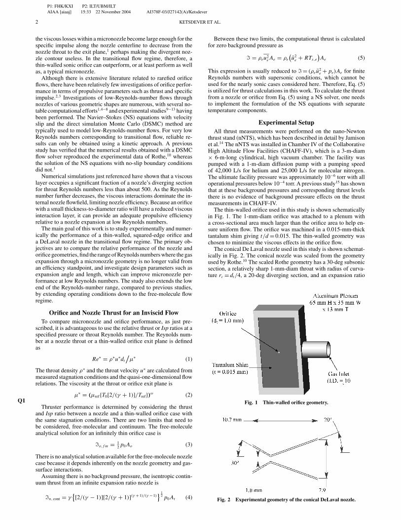
To better understand the impact of the viscous effects on thenozzle efficiency for different nozzle geometries and chamber pres-sures, the specific impulse has been calculated as a function of theaxial distance from the nozzle throat to the exit. Figure 14a showsthe specific impulse profiles for three values of the nozzle length forRe∗ = 60. Consider first the baseline length of L = 1.07 × 10⁻² m.Figure 14a shows that the specific impulse increases sharply overthe first millimeter past the throat. Further downstream the specificimpulse had a maximum and then decreased toward the nozzle-exitplane as the influence of the viscous layer increases. Note that themaximum that occurs at X ≈ 0.4L was about 5% larger than thatat the nozzle exit. The numerical results indicated that shorteningthe nozzle generally resulted in higher axial-flow velocities at thenozzle-exit plane close to the centerline caused by a smaller impactof the viscous layer. However, the total Isp increase amounts to onlyabout 4% when the nozzle was three times shorter than the baselinecase for Re∗ = 60.
As expected, an increase in the Reynolds number resulted in betternozzle efficiencies, as shown in Fig. 14b for Re∗ = 200 and threevalues of the nozzle length. Still, there was a maximum in the specificimpulse observed inside the nozzle. The location of the maximumshifted downstream as compared to Re∗ = 60 caused by the thinnerviscous layer. The value of Isp at the nozzle exit was about 2%lower than the maximum value inside the nozzle. The shortening ofthe nozzle causes about a 1% decrease with the relative position ofthe maximum being closer to the exit plane for shorter nozzles. Asmaller influence of the viscous layer for larger Reynolds numberflows was the reason for an insignificant impact of the nozzle length.The difference between the cases of L/2 and L/3 in terms of thenozzle efficiency was less than 1%.
The second nozzle geometry parameter varied was the angle of thediverging section. It is well known that conventional high-Reynolds-
a)
b)
Fig. 14 Impact of the nozzle length on performance for helium:a) Re∗ = 60 and b) Re∗ = 200.
number conical nozzles are usually designed with a half-angle ofabout 15 deg, where the nozzle efficiency is maximum. For lowReynolds numbers, the viscous effects become a significant issuethat degrades nozzle performance. Therefore, it appeared reasonableto increase the half-angle of the diverging section in order to improvethe efficiency. The numerical studies in this work were carried outfor the half-angle from 20 deg (baseline geometry) up to 40 deg. Theangle was increased while maintaining a constant diverging sectionwall length lw .
Specific impulse as a function of axial station for four differenthalf-angle values and Re∗ = 60 is given in Fig. 15a. Although thegeneral shape of the Isp distribution does not change significantlywith angle, there were several important effects associated with theangle increase. In contrast to the nozzle length change at a con-stant angle, where the flow was essentially constant over the firstmillimeter from the throat, the varying angle impacted the specificimpulse immediately after the throat. A larger angle caused highervalues of axial velocity, which generally resulted in higher thrustand Isp in the diverging section of the nozzle. Further downstream,the viscous layer decreased the nozzle efficiency, which was espe-cially pronounced for smaller angles. A noticeably better nozzleperformance was seen for larger angles. Every 5-deg increase inthe angle resulted in about a 2% increase in the specific impulse atthe nozzle-exit plane for Re∗ = 60. At larger Reynolds numbers, the

P1: FHK/KXI P2: ILT/UBM/ILTAIAA [aiaaj] 15:33 22 November 2004 AI378F-03/J27142(A)/Ketsdever
8 KETSDEVER ET AL.
a)
b)
Fig. 15 Impact of the nozzle expansion angle on performance for he-lium: a) Re∗ = 60 and b) Re∗ = 200.
increase of the nozzle angle does not have a strong impact on theflow in the region of the throat, as illustrated in Fig. 15b.
The thrust and specific impulse results for all geometric con-ditions are summarized in Table 2. The general conclusion thatcan be drawn from Table 2 is that the increase of the nozzle an-gle and/or decrease of the nozzle length increased the thrust andimproved the nozzle efficiency for Reynolds numbers less than ap-proximately 100. This geometric improvement decreased with in-creasing Reynolds number and is within 1 or 2% for all geometriesconsidered at Re∗ = 200.
Numerical and Experimental UncertaintiesThere are several uncertainties associated with the experimen-
tal effort in this study. First, corrections to the force measurementscaused by the facility background gas have not been incorporatedinto the data analysis. However, a previous study15 indicated that thethrust can be effected by less than 0.5% at the experimental condi-tions of this work. Second, the standared deviation of the stagnationpressure and mass flow measurements were found to be within ap-proximately 1% over the range used. Third, thrust stand calibrationof deflection vs applied force has been approximated to be within3%. For a given applied force to the thrust stand, the standard de-viation of the stand’s deflection was less than 1%; however, theaccuracy of the calibration system must also be taken into account.
Table 2 Numerical data for the performance of variousnozzle geometries
Angle, deg Re∗ Length Tn , N Ispn , s Ispn/IspNom
20 60 Nominal lw 8.01E−04 140.53 1.00lw/2 8.25E−04 144.14 1.03lw/3 8.33E−04 145.55 1.04
200 Nominal lw 3.28E−03 155.38 1.00lw/2 3.29E−03 157.14 1.01lw/3 3.29E−03 157.23 1.01
25 60 lw 8.33E−04 144.14 1.03lw/2 8.42E−04 146.43 1.04
200 lw 3.32E−03 157.57 1.01lw/2 3.34E−03 158.17 1.02
30 60 lw 8.58E−04 148.14 1.05200 lw 3.33E−03 159.12 1.02
40 60 lw 8.82E−04 151.76 1.08200 lw 3.34E−03 159.10 1.02
Finally, there was some error associated with the manufacturingof the orifice and nozzle. In general, the nozzle throat diameter isknown to within 0.5%. Because the orifice was machined from athin tantalum shim, the measurement of its diameter is not quite asaccurate and is estimated to be within approximately 2%.
In addition to the experimental uncertainties, there are a numberof numerical uncertainties. Grid resolution, the maximum numberof simulated molecules, effects of the subsonic boundary condi-tions, and the gas-gas collision models all account for a numericaluncertainty estimated to be on the order of 1 to 2%. The effects ofthe nozzle surface roughness present in the experimental device arenot known, although a simple diffuse-antispecular model was used.However, it is not known to what extent the nozzle surface roughnesscontributes to uncertainties in either the numerical or experimentaldata.
ConclusionsLow-Reynolds-number flows through nozzle and orifice geome-
tries have been investigated both numerically and experimentally.The direct simulation Monte Carlo (DSMC) results show that theviscous effects dominate the flow for Re∗ = 60. This result has beenseen in previous studies1 and prompted the investigation of thin-walled orifices for thrust generation because presumably an orificewould not exhibit large viscous interaction regions. Experimentalresults indicate that at Re∗ < 100 the thrust generated by an orificeis indeed larger than that of the nominal conical nozzle for heliumand nitrogen. However, the nozzle remains more efficient (based onIsp) than the orifice throughout the range of Isp investigated. Thereis a minimum in the nozzle-to-orifice specific impulse ratio aroundRe∗ = 60 for helium. Therefore at some Reynolds numbers, it mightbe advantageous to use a simple orifice geometry in this range overa nozzle geometry that is complicated to fabricate.
In general, the experimental and numerical results for the nozzle-to-orifice thrust ratio are in good agreement (within a few percent).The results obtained with an antispecular gas-surface interactonmodel for DSMC show better qualitative agreement with the slope ofthe thrust ratio data than the standard Maxwell model. The antispec-ular model was investigated based on scanning electron microscopeimages of the nozzle’s surface roughness caused by the machiningprocess. Although the exact influence of the surface roughness isunknown, it appears to have a measurable effect on the nozzle’sperformance.
Once the DSMC model results were verified using experimen-tal data, the model was used to assess geometrical variations onthe conical nozzle’s performance. Both the diverging section lengthand angle were varied to assess the effect on nozzle performance.Little effect was seen in improving the performance for Re∗ = 200where all variations were within 2%. However, an 8% improve-ment in Isp was seen for a Re∗ = 60 helium flow when the expan-sion angle was doubled from 20 to 40 deg. At Re∗ = 60, it wasalso shown that shortening the diverging section length improvedthe nozzle’s performance. Previous studies6 have shown that using

P1: FHK/KXI P2: ILT/UBM/ILTAIAA [aiaaj] 15:33 22 November 2004 AI378F-03/J27142(A)/Ketsdever
KETSDEVER ET AL. 9
trumpet geometries can further improve the performance over a con-ical geometry by as much as 5% at low Reynolds number. Therefore,reasonable improvement of nozzle performance for Re∗ < 100 canbe realized through the use of numerical simulations to optimizegeometry.
AcknowledgmentsThis work was supported in part by the U.S. Air Force Office of
Scientific Research and the Propulsion Directorate of the Air ForceResearch Laboratory at Edwards Air Force Base, California. Theauthors wish to thank Andrew Jamison and Taylor Lilly for theirinvaluable assistance with this research.
References1Ivanov, M., Markelov, G., Ketsdever, A., and Wadsworth, D., “Numerical
Study of Cold Gas Micronozzle Flows,” AIAA Paper 99-0166, Jan. 1996.2Ketsdever, A., “Thrust Measurements of an Underexpanded Orifice in the
Transitional Regime,” Proceedings of the 23rd International Symposium onRarefied Gas Dynamics, edited by A. Ketsdever and E. P. Muntz, AmericanInst. of Physics, New York, 2002, pp. 1057–1064.
3Alexeenko, A., Gimelshein, S., Levin, D., Ketsdever, A., and Ivanov, M.,“Measurements and Simulation of Orifice Flow for Micropropulsion Test-ing,” Journal of Propulsion and Power, Vol. 19, No. 4, 2003, pp. 588–594.
4Kim, S., “Calculations of Low-Reynolds-Number Resistojet Nozzles,”Journal of Spacecraft and Rockets, Vol. 31, No. 2, 1994, pp. 259–264.
5Boyd, I., Jafry, Y., and Vanden Beukel, J., “Particle Simulations of He-lium Microthruster Flows,” Journal of Spacecraft and Rockets, Vol. 31, No. 2,1994, pp. 271–277.
6Zelesnik, D., Micci, M., and Long, L., “Direct Simulation Monte CarloModel of Low Reynolds Number Nozzle Flows,” Journal of Propulsion andPower, Vol. 10, No. 4, 1994, pp. 546–553.
7Chung, C.-H., Kim, S., Stubbs, R., and De Witt, K., “Low-Density Noz-zle Flow by the Direct Simulation Monte Carlo and Continuum Mehtods,”Journal of Propulsion and Power, Vol. 11, No. 1, 1995, pp. 64–78.
8Alexeenko, A., Levin, D., Gimelshein, S., Collins, R., and Reed, B., “Nu-merical Study of Flow Structure and Thrust Performance for 3-D MEMS-Based Nozzles,” AIAA Paper 2002-3194, June 2002.
9Murch, C., Broadwell, J., Silver, A., and Marcisz, T., “Low-Thrust Noz-zle Performance,” AIAA Paper 68-091, Jan. 1968.
10Rothe, D., “Electron-Beam Studies of Viscous Flow in Supersonic Noz-zles,” AIAA Journal, Vol. 9, No. 5, 1971, pp. 804–810.
11Whalen, M., “Low Reynolds Number Nozzle Flow Study,” NASATM100130, July 1987.
12Lempert, W., Boehm, M., Jiang, N., Gimelshein, S., and Levin, D.,“Comparison of Molecular Tagging Velocimetry Data and Direct SimulationMonte Carlo Simulation in Supersonic Micro Jet Flows,” Experiments inFluids, Vol. 34, 2003, pp. 403–411. Q3
13Jamision, A., and Ketsdever, A., “Low Reynolds Number PerformanceComparison of an Underexpanded Orifice and a DeLaval Nozzle,” Proceed-ings of the 23rd International Symposium on Rarefied Gas Dynamics, editedby A. Ketsdever and E. P. Muntz, American Inst. of Physics, New York,2002, pp. 557–564.
14Jamison, A., Ketsdever, A., and Muntz, E. P., “Gas Dynamic Calibrationof a Nano-Newton Thrust Stand,” Review of Scientific Instruments, Vol. 73,No. 10, 2002, pp. 3629–3637.
15Ketsdever, A., “Facility Effects on Performance Measurements of Mi-cropropulsion Systems Which Utilize Gas Expansion,” Journal of Propul-sion and Power, Vol. 18, No. 4, 2002, pp. 797–804.
16Selden, N., and Ketsdever, A., “Comparison of Force Balance Calibra-tion Techniques for the Nano-Newton Range,” Review of Scientific Instru-ments, Vol. 74, No. 12, 2003, pp. 5249–5254.
17Ivanov, M. S., Markelov, G. N., and Gimelshein, S. F., “Statistical Sim-ulation of Reactive Rarefied Flows: Numerical Approach and Applications,”AIAA Paper 98-2669, June 1998. Q4
18Ivanov, M. S., and Rogasinsky, S. V., “Analysis of the Numerical Tech-niques of the Direct Simulation Monte Carlo Method in the Rarefied GasDynamics,” Soviet Journal Numer. Anal. Math. Modeling, Vol. 3, No. 6,1988, pp. 453–465. Q5
19Borgnakke, C., and Larsen, P. S., “Statistical Collision Model for MonteCarlo Simulation of Polyatomic Gas Mixture,” Journal of ComputationalPhysics, Vol. 18, 1975, pp. 405–420. Q6
20Gimelshein, S. F., Boyd, I. D., and Ivanov, M. S., “Modeling of InternalEnergy Transfer in Plume Flows of Polyatomic Molecules by the DSMCMethod,” AIAA Paper 99-0738, Jan. 1999.
21Arkilic, E. B., Breuer, K. S., and Schmidt, M. A., “Mass Flow and Tan-gential Momentum Accommodation in Silicon Micromachined Channels,”Journal of Fluid Mechanics, Vol. 437, 2001, pp. 29–43.
C. KaplanAssociate Editor

P1: FHK/KXI P2: ILT/UBM/ILTAIAA [aiaaj] 15:33 22 November 2004 AI378F-03/J27142(A)/Ketsdever
Queries
Q1. Unless there’s a reason to use a specific type of enclosure, enclosures should go in the order {[({[(....)]})]}. OK as set?Q2. Spell out acronym.Q3. Give issue number (month is acceptable if there is no issue number).Q4. If this was subsequently published in an archival source, give full publication information.Q5. Spell out journal name in full.Q6. Give issue number (month is acceptable if there is no issue number).


![Numerical Determination of Two-Phase Material Parameters ... · Numerical Determination of Two-Phase Material Parameters of a ... virtually using methods of stochastic geometry [14],](https://static.fdocuments.net/doc/165x107/5f0f4f6b7e708231d4438708/numerical-determination-of-two-phase-material-parameters-numerical-determination.jpg)