![experiment no. 3.4 scintillation - Universität zu Köln€¦ · Atthispoint,pleaserefertothetextbooks„Kernphysik“,byTheoMayer-Kuckuk[9]and„Modern Nuclear Chemistry“ by Loveland,](https://static.fdocuments.net/doc/165x107/5f085aca7e708231d42198ca/experiment-no-34-scintillation-universitt-zu-kln-atthispointpleaserefertothetextbooksakernphysikaoebytheomayer-kuckuk9andamodern.jpg)
Experiment no. 3 - IKP: Institut für Kernphysik · 2017-03-08 · Experiment no. 3.7 Coulomb...
16
Institute for Nuclear Physics, University of Cologne Practical Course Master Experiment no. 3.7 Coulomb scaering of identical particles, spin and statistics at the tandem accelerator as of April 15, 2016 Abstract The angular distributions of elastically scattered identical bosons ( 12 C on 12 C) and fermions ( 13 C on 13 C) are investigated at the Cologne tandem accelerator, using particle energies well below the Coulomb barrier. Due to the exchange symmetry the distribution of the scattered particles is symmetric around Θ c.m. = 90 ◦ . Moreover, the exchange sym- metry causes an interference pattern, similar to the one of a double slit, which depends in a distinctive manner on the spin and statistics of the scattering particles. Additionally, the ex- periment gives insight into the operation of a particle accelerator, the electronic measuring equipment and the typical data analysis. 1 Introduction 1 2 Preparation 2 3 Theoretical Considerations 3 3.1 Proposed beam energy ..................................... 6 3.2 Count rates, target thicknesses and solid angle ........................ 6 3.3 Miscellaneous .......................................... 6
Transcript of Experiment no. 3 - IKP: Institut für Kernphysik · 2017-03-08 · Experiment no. 3.7 Coulomb...

Institute for Nuclear Physics, University of Cologne
Practical Course Master
Experiment no. 3.7Coulomb scaering of identical particles,
spin and statisticsat the tandem accelerator
as of April 15, 2016
Abstract
The angular distributions of elastically scattered identical bosons (12
C on12
C) and
fermions (13
C on13
C) are investigated at the Cologne tandem accelerator, using particle
energies well below the Coulomb barrier. Due to the exchange symmetry the distribution
of the scattered particles is symmetric around Θc.m. = 90. Moreover, the exchange sym-
metry causes an interference pattern, similar to the one of a double slit, which depends in a
distinctive manner on the spin and statistics of the scattering particles. Additionally, the ex-
periment gives insight into the operation of a particle accelerator, the electronic measuring
equipment and the typical data analysis.
1 Introduction 1
2 Preparation 2
3 Theoretical Considerations 33.1 Proposed beam energy . . . . . . . . . . . . . . . . . . . . . . . . . . . . . . . . . . . . . 6
3.2 Count rates, target thicknesses and solid angle . . . . . . . . . . . . . . . . . . . . . . . . 6
3.3 Miscellaneous . . . . . . . . . . . . . . . . . . . . . . . . . . . . . . . . . . . . . . . . . . 6

2 2 PREPARATION
4 Setup 74.1 Vacuum . . . . . . . . . . . . . . . . . . . . . . . . . . . . . . . . . . . . . . . . . . . . . . 7
4.2 Apertures . . . . . . . . . . . . . . . . . . . . . . . . . . . . . . . . . . . . . . . . . . . . . 7
4.3 Adjustment of the target position . . . . . . . . . . . . . . . . . . . . . . . . . . . . . . . 8
4.4 Scattering chamber . . . . . . . . . . . . . . . . . . . . . . . . . . . . . . . . . . . . . . . 8
4.5 Electronics . . . . . . . . . . . . . . . . . . . . . . . . . . . . . . . . . . . . . . . . . . . . 9
5 Experimental Procedure 9
6 Data Acquisition 9
7 Analysis 10
A Quantum mechanical solution of the Coulomb problem 11
B Sicherheitshinweise 12
Literaturverzeichnis 16
1 IntroductionIn this experiment scattering of
12C and
13C particles at a
12C and
13C target is investigated.
The aim is to determine scattering cross sections for the reactions of identical particles and
non-identical particles as a function of the scattering angle. The experiment takes place at the
FN tandem-Van-de-Graa accelerator of the Institute for Nuclear Physics. The12
C and13
C ions
are accelerated to 10 MeV and hit the target in the target chamber. Inside the chamber seven Si
detectors are mounted on a rotatable bulging disk. They detect the scattered particles at angles
between 10
and 80.
This experiment is based on experiment M3.3 – Rutherford scattering – which investigates
scattering of α particles at a gold foil. Now, using identical bosons and fermions as target
and projectile, quantum-mechanical eects are observed. With the tandem accelerator high
statistics are yielded. Working with this setup (as shown in Fig. 1), this kind of electronics and
digital data acquisition gives insights in state-of-the-art experiments.
2 PreparationPlease read the manual for experiment no. M3.3 – Rutherford scattering – including the liter-
ature listed in the manual. Experiment M3.3 deals with the historical experiments of Geiger,
Marsden, Rutherford and Cadwick. The used formula for the Rutherford scattering angle and
the relation between the detected counting rate anddσ (Θ)
dΩ are valid in general.

3
(a) Scattering chamber. (b) Si detector with aperture.
Figure 1: View into the scattering chamber downstream the beam. In the center of the chamber the targetladder is placed, on the left the seven Si detectors, mounted on a rotatable bulging disk. On the right picturea detector and its aperture is shown in detail.
Please prepare the following topics:
• Theoretical basics:
Rutherford cross section, quantum-mechanical scattering amplitudes, spin and statistics
of bosons and fermions, interference by scattering of identical particles.
• Working principle of a tandem-Van-de-Graa accelerator:
beam production, beam transport, focussing, vacuum pumping stations.
• Experimental setup:
Setup of the scattering chamber, working principle of Si detectors, dierence between
Si detectors and HPGe detectors, electronic components, especially working principle of
digital-gamma-nder modules (DGF) and the dierence between analog and digital data
acquisition in nuclear physics.
3 Theoretical ConsiderationsExperiment M3.3 investigates Coulomb scattering of α– particles, which hit a gold target at
energies below the Coulomb barrier (what is the Coulomb barrier?). This experiment could
also be performed at the tandem accelerator and would show the same scattering pattern with
a higher intensity.
However, using identical particles as projectile and target, the scattering pattern shows that
this reaction can – for any energy – only be treated quantum mechanically.
• A measured particle in the detector at an angle Θ can either be a scattered projectile in
forward direction or be a backscattered recoil particle (scattered with the angle π–Θ).

4 3 THEORETICAL CONSIDERATIONS
The angular distribution in the center-of-mass system is symmetric around π /2 (as a con-
sequence of the exchange symmetry of identical particles).
• Due to their indistinguishability both contributions interfere. Thus, an interference pat-
tern (oscillations) can be observed for the dierential cross section as a function of the
scattering angle for energies below the Coulomb barrier. This is not related to diraction
patterns due to nuclear interactions at higher energies. The interference patterns derive
from the fact that the cross section has to be calculated quantum mechanically:
[dσdΩ
=f 2 = f (Θ) ± f (π – Θ)2
]
• It can be shown, that the interference pattern depends on whether the identical particles
are bosons or fermions; here the relation between spin and statistics is important (sym-
metrical or anti-symmetrical wave function).
Scattering of identical particles: Exchange symmetry for two dierent statistics (rst for
spin-less particles):
P12Ψ = ±Ψ
+ for bosons
– for fermions
dσdΩ
= |f (Θ)|2 + |f (π – Θ)|2 + 2<f (Θ)f ∗(π – Θ) for bosons
dσdΩ
= |f (Θ)|2 + |f (π – Θ)|2 – 2<f (Θ)f ∗(π – Θ) for fermions
• For particles with spin , 0 the contributions (S = sProjektil
+sTarget
) have to be consid-
ered. For fermions the Pauli principle requires antisymmetry in space and time. For two
identical spin-1/2-particles there are two possibilities: Total spin as a singulett, S = 0
(antisymmetry for spin exchange, weighted with 1/4) or as a triplett S = 1 (symmetry
for spin exchange, weighted with 3/4). The dierent parts of cross sections with their
symmetries (+ or –) have to be summed up incoherently with their weighting factors.
The interference term has the factor +2 as singulett and –2 as triplett. Considering the
weighting factors the total factor is –1. Thus, the interference term has the opposite sign
as for bosons. The spin multiplicity weakens this eect. The Mott formula describes this
phenomenon. For I → ∞ the contribution of the interference disappears and the classi-
cal case of Bohrs correspondence principle is observed. Here the general Mott formula
is given for Coulomb scattering of identical particles with spin s in the center-of-mass
system (for the derivation see Ref. [4]:
dσdΩ
=
(1
4πϵ0·
Z2e2
4E
)2
1
sin4 Θ2
+
1
cos4 Θ2
+
2(–1)2s
(2s + 1)
cos[ηS ln tan2 Θ2]
sin2 Θ2cos
2 Θ2

5
It consists of the forward scattering term, the backscattering contribution and the spin- in-
dependent interference term, whereηS is the Sommerfeld parameterηS = (Z2e2/h)√
µred2Elab
with the reduced mass µred , or numerically:
ηS = 0.1574 · Z2
√AProjektil
Elab(MeV )
(What is the meaning of the Sommerfeld parameter?) It is interesting that the interference
pattern for bosons diers from the pattern for fermions (due to the sign of the interference
term) and that lower spins lead to stronger interference.
• It is important to use beam energies below the Coulomb barrier. Otherwise, Rutherford
scattering in combination with nuclear forces would occur, i.e. diraction patterns in the
dierential cross section. When the projectile gets in contact with the target at an energy
above the Coulomb barrier, it is aected by strong interaction. By this, for example,
nuclear radii can be determined.
• Choice of particles12
C and13
C are ideal cases:
– Spin I = 0 for bosons, smallest possible spin I = 1
2for fermions.
– Both are available as beam and/or target.
– The classical case of distinguishable particals is also achievable.
• Choice of energyFollowing aspects have to be considered:
– Energy must be below the Coulomb barrier:
EC =
Z1Z2e2
r0(A1/3
1+ A1/3
2)
≈1, 44Z1Z2
1, 2 · (A1/3
1+ A1/3
2)
(MeV),
to avoid diraction/interference eects from nuclear interaction. For12
C on12
C
(13
C on13
C) the Coulomb barrier is at Ec.m.= 9.43 (9.19) MeV, which means in the
lab frame 18.86 (18.38) MeV.
– The width of the interference should allow for a measurement of several oscillations
within the available detection angles. This is related to the Sommerfeld parameter:
ηS = 0.1574 · Z2
√AProj
Elab(MeV )
It should be signicantly >1, because for small values the interference width is big-
ger than the detection angle and a classical distribution is detected (quantum me-
chanics include a dierent factor ±2 (without spins) at 90
compared to the classical
Rutherford cross section). Moreover, it should not be 1. This would lead to very
fast oscillations, which cannot be resolved: a “classical” cross section is observed.
6 3 THEORETICAL CONSIDERATIONS
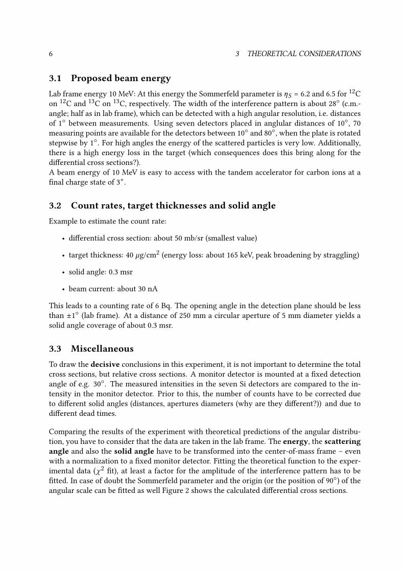
3.1 Proposed beam energyLab frame energy 10 MeV: At this energy the Sommerfeld parameter is ηS = 6.2 and 6.5 for
12C
on12
C and13
C on13
C, respectively. The width of the interference pattern is about 28
(c.m.-
angle; half as in lab frame), which can be detected with a high angular resolution, i.e. distances
of 1
between measurements. Using seven detectors placed in anglular distances of 10, 70
measuring points are available for the detectors between 10
and 80, when the plate is rotated
stepwise by 1. For high angles the energy of the scattered particles is very low. Additionally,
there is a high energy loss in the target (which consequences does this bring along for the
dierential cross sections?).
A beam energy of 10 MeV is easy to access with the tandem accelerator for carbon ions at a
nal charge state of 3+.
3.2 Count rates, target thicknesses and solid angleExample to estimate the count rate:
• dierential cross section: about 50 mb/sr (smallest value)
• target thickness: 40 µg/cm2
(energy loss: about 165 keV, peak broadening by straggling)
• solid angle: 0.3 msr
• beam current: about 30 nA
This leads to a counting rate of 6 Bq. The opening angle in the detection plane should be less
than ±1
(lab frame). At a distance of 250 mm a circular aperture of 5 mm diameter yields a
solid angle coverage of about 0.3 msr.
3.3 MiscellaneousTo draw the decisive conclusions in this experiment, it is not important to determine the total
cross sections, but relative cross sections. A monitor detector is mounted at a xed detection
angle of e.g. 30. The measured intensities in the seven Si detectors are compared to the in-
tensity in the monitor detector. Prior to this, the number of counts have to be corrected due
to dierent solid angles (distances, apertures diameters (why are they dierent?)) and due to
dierent dead times.
Comparing the results of the experiment with theoretical predictions of the angular distribu-
tion, you have to consider that the data are taken in the lab frame. The energy, the scatteringangle and also the solid angle have to be transformed into the center-of-mass frame – even
with a normalization to a xed monitor detector. Fitting the theoretical function to the exper-
imental data (χ2 t), at least a factor for the amplitude of the interference pattern has to be
tted. In case of doubt the Sommerfeld parameter and the origin (or the position of 90) of the
angular scale can be tted as well Figure 2 shows the calculated dierential cross sections.

7
Figure 2: Dierential cross sections in the center-of-mass frame, calculated for the scattering of 12C on 12Cand of 13C on 13C at Elab = 10 MeV, as a fuction of the c.m.-scattering angle.
4 SetupDue to the complex setup (cf. Fig. 3), several parts are explained in the following sections.
4.1 Vacuum
The experiment takes place at the experimental setup at the end of a beam line. It is important,
that the beam line (and the chamber) keeps a vacuum of 10–6
mbar. The beam line has two
pumping stations, which consist of a booster pump and a turbopump. (What are their func-
tions?) The vacuum has to be controlled during the entire experiment. In the worst case a
leakage of the beam line can lead to the venting of the whole accelerator.
4.2 Apertures
The beam in the beam line is controlled by apertures. These are electrically conducting ele-
ments, which are placed inside the beam line in regular distances. They are connected to am-
Figure 3: Schematical drawing of the setup of the beam line used in the experiment.
8 4 SETUP
peremeters at the control console of the tandem accelerator. When the beam hits an aperture,
an increased current is measured at the amperemeters. To focus the beam via magnet lenses,
the beam current at the apertures has to be minimized, while the current at the end of the beam
line, in the so-called Faraday cup, has to be maximized.
4.3 Adjustment of the target position
When the beam is focussed, the experiment can start. Therefore the target (i.e.12
C or13
C) is
moved into the beam. The target is placed on a target ladder, which can be moved by a motor
from outside the chamber. Before the experiment starts (and even before beam focussing) the
position of all targets on the target ladder have to be adjusted by using a laser. On the target
ladder there are also some apertures mounted, which have dierent sizes and which are used
for focussing.
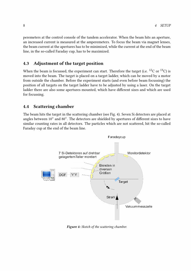
4.4 Scattering chamber
The beam hits the target in the scattering chamber (see Fig. 4). Seven Si detectors are placed at
angles between 10
and 80. The detectors are shielded by apertures of dierent sizes to have
similar counting rates in all detectors. The particles which are not scattered, hit the so-called
Faraday cup at the end of the beam line.
Figure 4: Sketch of the scattering chamber.
4.5 Electronics 9
4.5 Electronics
The signals of the Si detectors are amplied and shaped by preampliers, before they are fed
into digital-gamma-nder modules (DGF). The DGFs digitize the analog signals. Finally, the
digital information is read out by a computer and sorted into spectra.
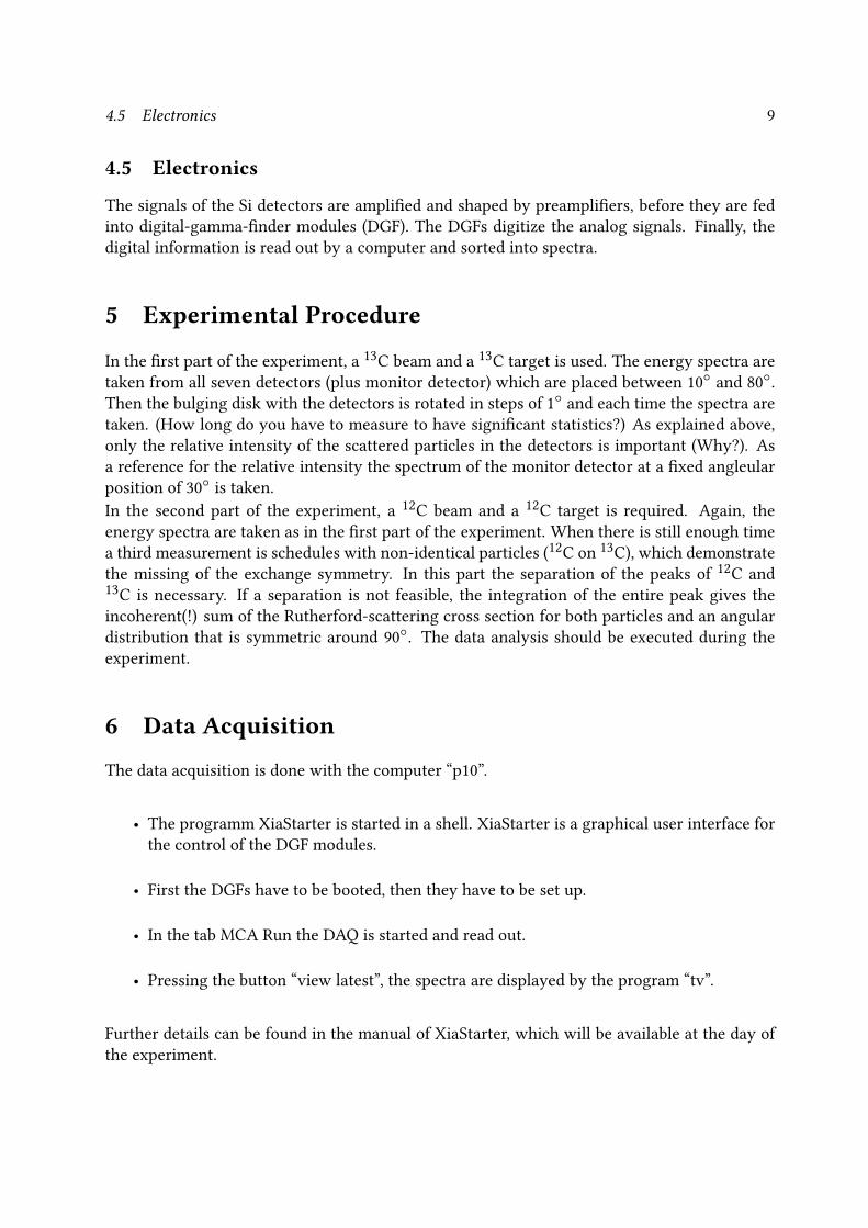
5 Experimental Procedure
In the rst part of the experiment, a13
C beam and a13
C target is used. The energy spectra are
taken from all seven detectors (plus monitor detector) which are placed between 10
and 80.
Then the bulging disk with the detectors is rotated in steps of 1
and each time the spectra are
taken. (How long do you have to measure to have signicant statistics?) As explained above,
only the relative intensity of the scattered particles in the detectors is important (Why?). As
a reference for the relative intensity the spectrum of the monitor detector at a xed angleular
position of 30
is taken.
In the second part of the experiment, a12
C beam and a12
C target is required. Again, the
energy spectra are taken as in the rst part of the experiment. When there is still enough time
a third measurement is schedules with non-identical particles (12
C on13
C), which demonstrate
the missing of the exchange symmetry. In this part the separation of the peaks of12
C and
13C is necessary. If a separation is not feasible, the integration of the entire peak gives the
incoherent(!) sum of the Rutherford-scattering cross section for both particles and an angular
distribution that is symmetric around 90. The data analysis should be executed during the
experiment.
6 Data Acquisition
The data acquisition is done with the computer “p10”.
• The programm XiaStarter is started in a shell. XiaStarter is a graphical user interface for
the control of the DGF modules.
• First the DGFs have to be booted, then they have to be set up.
• In the tab MCA Run the DAQ is started and read out.
• Pressing the button “view latest”, the spectra are displayed by the program “tv”.
Further details can be found in the manual of XiaStarter, which will be available at the day of
the experiment.

10 7 ANALYSIS
7 Analysis1. Analysis of the spectra with the program “tv”:
The peak intensity I0 is determined, integrating the peak and subtracting the background.
2. Dead-time correction:
During the measurement for each detector two times are written to disk: Runtime and
Livetime. The Runtime is the time span when the system is running, while the Livetime
is the time when the system actually took data. The quotient of both gives the dead time
tdead of the data acquisition system. This has to be taken into account for the calculation
of the intensity:
I1 = I0 · (1 + 0.01 · tdead ),
where tdead is given percentagewise.
3. Solid angle correction:
For the transformation of the solid angle into the center-of-mass frame is:
I2 =I1
cos(θlabor )
4. Aperture correction:
The dierent sizes of the apertures in front of the detectors have to be considered (Why?).
All apertures are circular, thus:
I3 =I2r2B
5. Normalization to the count rate of the monitor detector:
The determined intensities have to be normalized to the count rate of the monitor detec-
tor. Therefore the dead-time correction of the measured intensity of the monitor detector
must be considered as well: IMon,kor = IMon · (1 + 0.01 · ttot)
I4 =I3
IMon,kor
6. Angular correction:
To change to the center-of-mass system for particles of the same weight, the the angles
have to be multiplied by a factor of 2:
θ∗c.m.= 2 · θlabor
7. Determine the Sommerfeld parameter η.

11
A Quantummechanical solution of the Coulomb problemThe Schrödinger equation is:
[–
h2
2µu′′
+
(Cr+
h2
2µ
`(` + 1)
r2–
h2k2
2µ
)u` = 0
]
This leads to the canonic form with the Sommerfeld parameter ηS and ρ = kr :
[d2u`(ρ)
dρ2+
(1 –
`(` + 1)
ρ2– 2
ηSρ
)u`(ρ) = 0
]
Asymptotic solutions are the regular and irregular Coulomb functions with Coulomb phases:
σ` = argΓ(` + 1 + iηS):[F` −→ sin(kr – `π /2 – ηS ln 2kr + σ`)]
[G` −→ cos(kr – `π /2 – ηS ln 2kr + σ`)]
With this we get in the well-known partial wave expansion for the incoming plane wave the
Coulomb scattering amplitude of the outgoing wave:
[ΨS −→
1
rei(kr–ηS ln 2kr)fc(Θ)
]
fc(Θ) = –ηS
e2iσ0 · eiηS ln sin2 Θ/2
2k2 sin2Θ/2
The square fC · f ∗C gives the classical Rutherford formula. It aects (with the logarithmic phase
(long range of the Coulomb force(!)) and the s-wave Coulomb phaseσ0) the term of interference.
In such a case the partial wave expansion cannot be aborted at low ` values.

12 B SICHERHEITSHINWEISE
B Sicherheitshinweise
Operating instructions for electric powered equipment in the rooms for the practical course
Danger for people Burns or death by high electric currents
Safety measures: Pay attention that cables and plugs are not damaged and use them only in the way they are
designed for.
In case of damage, or if you have the suspicion that they are damaged inform immediately
your supervisor, do not try to repair anything yourself.
Use at maximum one extension cord and only for low powered equipment.
For equipment with large power consumption only wall outlets should be used.
In case of emergency: Pull the mains plug.
In case of fire: Switch of all electrical equipment as far as possible.
First aid:People who can give first aid are Görgen, Rolke, Rudolph, Thiel
In case of shock call immediately an emergency physician Tel. 01-112 (from any telephone in
the institute, or mobile 112)
Hospital for accidents: evangelisches Krankenhaus Weyertal.
In case of all accidents also the managing director of the institute has to be informed.
In case of a working inability of 3 or more days an accident report form available from the
secretary has to be filled.
The first aid box can be found in the inner stairwell.
13/11/2014
Blazhev

13
Operating instructions for high voltage equipment in the rooms for the practical course
Danger for people Instantaneous death by ventricular fibrillation
Safety measures: Pay attention that cables and plugs are not damaged and use them only in the way they are
designed for.
In case of damage, or if you have the suspicion that they are damaged inform immediately
your supervisor, do not try to repair anything yourself.
Switch on the high tension only after the cables have been connected and switch it of before
disconnecting.
In case of emergency:Switch of the high tension
In case of fire: Switch of all electrical equipment as far as possible
First aid:People who can give first aid are Görgen, Rolke, Rudolph, Thiel
In case of shock call immediately an emergency physician Tel. 01-112 (from any telephone in
the institute, or mobile 112)
Hospital for accidents: evangelisches Krankenhaus Weyertal.
In case of all accidents also the managing director of the institute has to be informed.
In case of a working inability of 3 or more days an accident report form available from the
secretary has to be filled.
The first aid box can be found in the inner stairwell.
13/11/2014
Blazhev

14 B SICHERHEITSHINWEISE
Radiation protection directive for the handling of radioactive sources in the practical courses of the Institute of Nuclear Physics of the University of Cologne.
Issued 13/11/2014
1. Admission restrictions
Persons under the age of 18 years are not allowed to work in the practical course.
Pregnant women must not work with radioactive sources or in rooms in which radioactive sources are located.
Only students who have filled the registrations sheet and participated in the radiation protection instructions are allowed to carry out experiments with radioactive sources in the rooms of the practical course under the instruction of a supervisor. Visitors must not enter the rooms of the practical course when radioactive sources are located there.
2. Handling of radioactive sources
The radioactive sources are put in the experimental setup or in the lead shielding nearby by a radiation protection officer or an instructed person before the beginning of the practical course. These people document the issue in the list which is placed in the storage room (see appendix B). If radioactive sources have to be transported to other Physics institutes of the University of Cologne a list according to appendix A has to be attached to the transporting container.
When the practical course is finished the same people bring the radioactive sources back to the storage room.
A sign „Überwachungsbereich, Zutritt für Unbefugte verboten“ which means „monitored in-plant area, admission only for authorized personnel” has to be attached to the door of a room of the practical course when radioactive sources are inside.
It is not allowed to remove radioactive sources from the rooms of the practical course without contacting the radiation protection officer before.
During the practical course the radioactive sources must only be located at the place necessary for the measurements or behind the lead shielding nearby the experimental setup.
If you leave the rooms of the practical course make certain that doors are locked and windows are closed, even if you only leave for a short time.
Alpha-Sources are built in the experimental setup and students are not allowed to take them out.
Beta-Sources must only be handled by protective gloves or tweezers.

15
3. What to do in case of emergency
Any damages or suspected damages of radioactive sources must immediately be reported to
the supervisor or the radiation protection officer. It is not allowed to continue work with such
a source. Contaminated areas should be cordoned off immediately.
In case of fire, explosion or other catastrophic events besides the managing director and the
janitor a radiation protection officer must be called in.
4. Radiation protection officers
Radiation protection officers for radioactive sources in the Institute for Nuclear Physics of the
University of Cologne are:
Name Heinze Fransen Dewald
Responsibity Practical
course
Experimental
halls,
work with
radioactive
sources,
except of the
practical
course
Work in other
institutes,
Transport of
radioactive
sources,
accelerator

16 REFERENCES
References[1] Bethge, K.; Walter, G; Wiedemann, H.:
Kernphysik, eine EinführungSpringer (2008).
[2] Cohen-Tannoudji, C.; Diu, B.; Laloë, F.:
Quantenmechanik, Part 2De Gruyter (2010).
[3] Knoll, G.F.:
Radiation Detection and MeasurementJohn Wiley & Sons (2010).
[4] Joachain, C.:
Quantum Collision TheoryElsevier Science Ltd. (1979).
[5] Mayer-Kuckuk, T.:
KernphysikVieweg+Teubner Verlag (2002).