Experiment FO Falling Object - MIT OpenCourseWare
15
Experiment FO Falling Object Introduction We spend most of our time in the earth's gravitational field, so feeling the weight of objects and falling with constant acceleration are among our basic experiences. The International Committee on Weights and Measures has adopted as a standard value for the acceleration of a body freely falling in a vacuum g = 9.80665 m s -2 . The actual value of g varies as a function of elevation and latitude. If is the latitude and h the elevation in meters then the acceleration of gravity in SI units is -2 g = 9.80616 0.025928 cos(2 ) + 0.000069 cos 2 ( ) 3.086 10 4 h m s (4.1.1) This is known as Helmert’s equation. The strength of the gravitational force on the standard kilogram at 42 o latitude is 9.80 N kg -1 , and the acceleration due to gravity at sea level is therefore g = 9.80349 m s -2 for all objects. At the equator, g = 9.78 m s -2 , and at the poles g = 9.83 m s -2 . (This is because the radius of the Earth is larger at the equator than it is at the poles by about 26.5 km , and because the Earth rotates at 2 radians per day introducing an apparent repulsive force that flattens the spherical shape). Both the magnitude and the direction of the gravitational force also show variations that depend on local features to an extent that's useful in prospecting for oil and navigating submerged nuclear submarines. Such variations in g can be measured with a sensitive spring balance. Local variations have been much studied over the past two decades in attempts to discover a proposed "fifth force" which would fall off faster than the gravitational force that falls off as the inverse square of the distance between the masses. One can measure g by timing either a freely falling object or an object suspended from a support, oscillating as a pendulum. Principle of the Method In this experiment you'll time the free fall of a plastic wire nut by measuring the voltage across a capacitor in an RC charging circuit .The goal is to measure the time of fall of a wire nut as a function of the distance of fall. The distance is measured directly with a ruler. To measure the rather short time of fall, you will measure the voltage developed across a capacitor charged by an essentially constant current that flows only during the time the wire nut is falling. 1
Transcript of Experiment FO Falling Object - MIT OpenCourseWare

Experiment FO Falling Object
Introduction
We spend most of our time in the earth's gravitational field, so feeling the weight
of objects and falling with constant acceleration are among our basic experiences.
The International Committee on Weights and Measures has adopted as a
standard value for the acceleration of a body freely falling in a vacuum
g = 9.80665 m � s-2 . The actual value of g varies as a function of elevation and latitude.
If � is the latitude and h the elevation in meters then the acceleration of gravity in SI
units is
-2g = 9.80616 � 0.025928 cos(2�) + 0.000069 cos2 (�) � 3.086 � 10�4 h m � s (4.1.1)
This is known as Helmert’s equation. The strength of the gravitational force on the
standard kilogram at 42o latitude is 9.80 N � kg-1 , and the acceleration due to gravity at
sea level is therefore g = 9.80349 m � s-2 for all objects. At the equator, g = 9.78 m � s-2 ,
and at the poles g = 9.83 m � s-2 . (This is because the radius of the Earth is larger at the
equator than it is at the poles by about 26.5 km , and because the Earth rotates at 2� radians per day introducing an apparent repulsive force that flattens the spherical shape).
Both the magnitude and the direction of the gravitational force also show variations that
depend on local features to an extent that's useful in prospecting for oil and navigating
submerged nuclear submarines. Such variations in g can be measured with a sensitive
spring balance. Local variations have been much studied over the past two decades in
attempts to discover a proposed "fifth force" which would fall off faster than the
gravitational force that falls off as the inverse square of the distance between the masses.
One can measure g by timing either a freely falling object or an object suspended
from a support, oscillating as a pendulum.
Principle of the Method
In this experiment you'll time the free fall of a plastic wire nut by measuring the
voltage across a capacitor in an RC charging circuit .The goal is to measure the time of fall
of a wire nut as a function of the distance of fall. The distance is measured directly with a
ruler. To measure the rather short time of fall, you will measure the voltage developed
across a capacitor charged by an essentially constant current that flows only during the
time the wire nut is falling.
1
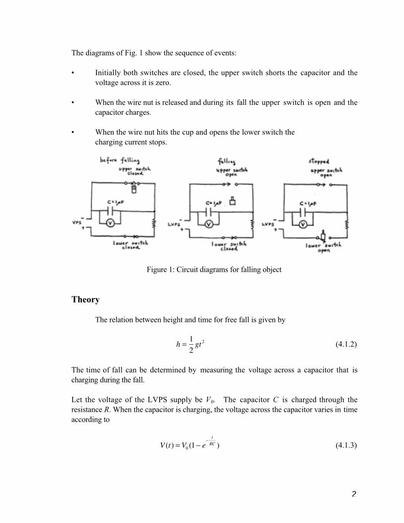
The diagrams of Fig. 1 show the sequence of events:
• Initially both switches are closed, the upper switch shorts the capacitor and the
voltage across it is zero.
• When the wire nut is released and during its fall the upper switch is open and the
capacitor charges.
• When the wire nut hits the cup and opens the lower switch the
charging current stops.
Figure 1: Circuit diagrams for falling object
Theory
The relation between height and time for free fall is given by
1h = gt 2 (4.1.2)
2
The time of fall can be determined by measuring the voltage across a capacitor that is
charging during the fall.
Let the voltage of the LVPS supply be V0. The capacitor C is charged through the
resistance R. When the capacitor is charging, the voltage across the capacitor varies in time
according to
t � RC )V (t ) = V0 (1 � e (4.1.3)
2

The voltage as a function of time is graphed in Figure 2.
Figure 2: Graph of voltage as a function of time for charging capacitor
You will study capacitors in detail in 8.02X so for the moment we will use this
charging voltage as a device to time how long the wire nut takes to fall a height h. wire nut
hits the cup and opens the lower switch the charging current stops. You will then make a
voltage measurement. So you will measure the quantities V, V0, R and C.
The time of flight is experimentally much less than the product RC. This means that the
exponential term in the expression for voltage, eq. (2), is approximately
t
e � RC � 1 �
t .
RC
Therefore the voltage is approximately
V (t ) = V0 (1 � e �
t
RC ) � V0 (1 � (1 � t
RC )) = V0
t
RC .
We can solve this equation for the time,
t � RC V (t )
V0
(4.1.4)
This equation tells us that our charging capacitor acts like a clock: the time elapsed is
proportional to the voltage across the capacitor.
Now that we have measured the time of falling in terms of V, we can solve eq. (1) for the
acceleration of gravity,
3

2h 2hV02
g = = t 2 (RCV )2
(4.1.5)
The time constant, � = RC , of the 1.0 mF capacitor and the 10 MW resistor is given b y
the nominal value,
� = RC = (1.0 � 107 �)(1.0 � 10�6 F) = 10s ,
that could be off by 10 % or more.
4

5
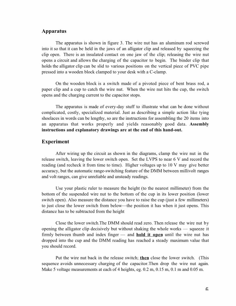
Apparatus
The apparatus is shown in figure 3. The wire nut has an aluminum rod screwed
into it so that it can be held in the jaws of an alligator clip and released by squeezing the
clip open. There is an insulated contact on one jaw of the clip; releasing the wire nut
opens a circuit and allows the charging of the capacitor to begin. The binder clip that
holds the alligator clip can be slid to various positions on the vertical piece of PVC pipe
pressed into a wooden block clamped to your desk with a C-clamp.
On the wooden block is a switch made of a pivoted piece of bent brass rod, a
paper clip and a cup to catch the wire nut. When the wire nut hits the cup, the switch
opens and the charging current to the capacitor stops.
The apparatus is made of every-day stuff to illustrate what can be done without
complicated, costly, specialized material. Just as describing a simple action like tying
shoelaces in words can be lengthy, so are the instructions for assembling the 20 items into
an apparatus that works properly and yields reasonably good data. Assembly
instructions and explanatory drawings are at the end of this hand-out.
Experiment
After wiring up the circuit as shown in the diagrams, clamp the wire nut in the
release switch, leaving the lower switch open. Set the LVPS to near 6 V and record the
reading (and recheck it from time to time). Higher voltages up to 10 V may give better
accuracy, but the automatic range-switching feature of the DMM between millivolt ranges
and volt ranges, can give unreliable and unsteady readings.
Use your plastic ruler to measure the height (to the nearest millimeter) from the
bottom of the suspended wire nut to the bottom of the cup in its lower position (lower
switch open). Also measure the distance you have to raise the cup (just a few millimeters)
to just close the lower switch from below—the position it has when it just opens. This
distance has to be subtracted from the height
Close the lower switch.The DMM should read zero. Then release the wire nut b y
opening the alligator clip decisively but without shaking the whole works — squeeze it
firmly between thumb and index finger — and hold it open until the wire nut has
dropped into the cup and the DMM reading has reached a steady maximum value that
you should record.
Put the wire nut back in the release switch; then close the lower switch. (This
sequence avoids unnecessary charging of the capacitor.Then drop the wire nut again.
Make 5 voltage measurements at each of 4 heights, eg. 0.2 m, 0.15 m, 0.1 m and 0.05 m.
6

Unsteady readings while holding the upper switch open arise from electrical
leakage. Be sure that you are not touching anything besides the alligator clip. Leakage may
be caused by high humidity, and a warm electric lamp nearby may help dry the apparatus
out.
Analysis
For each height h, average the voltage measurements and using the formula in
equation (3) for the time of a charging capacitor, calculate the time of fall.
Plot the square of the time (vertically) against h in m. There’s also a point at the
origin since it takes 0 time to fall 0 distance.
Fit the best straight line (by eye), and determine the slope. Since the relation
between height and time for free fall is given by
1h = gt 2 ,
2
the slope of your graph can be used to calculate your average value for g,
2 g = .
slope
7

Step-by-Step Assembly of Experiment FO Apparatus
Parts List
The parts are numbered as they appear in figures 4 and 5.
01 1” 1/8” Al rod
02 1 Wire Nut
03 8” 1/16” brass rod *
04 1’ #22 stranded wire
05 2 plastic stirrers
06 2 paper clips
07 2” 5kV test lead
08 1 paper cup *
09 2 cable clamps
10 2 #6 sheet metal screws
11 3 #6 steel washers
12 1 pre-drilled wood block * (ALSO USED IN EXPT. FM)
13 1 5/8” binder clip
14 1 alligator clip
15 1 solder lug
16 1 6-32 x 1/2" steel screw
17 1 6-32 steel nut
18 12” 1/2” PVC pipe *
19 1 10 MW resistor, 5%
20 1 1.0 mF 100-V capacitor, 10%,
The four items marked with an asterisk * are in the Redbox. The remainder are in a plastic
bag.
Preliminary
1) Fig. 5a Hold the 1 inch long piece of 1/8 inch aluminum rod (01) with your slip-joint
pliers and screw the wire nut (02) onto it so that they are firmly joined and the wire lies
along the central axis of the nut. This is the “falling object”, and is shown in Fig. 5a.
2) Fig. 4a. Hold the 8 inch long piece of 1/16 inch brass rod (03) with your slip-joint
pliers so that 4-3/4 inches sticks out sideways from the jaws of the pliers. Bend the rod
to a right angle as in Fig. 4a.
8

3) Strip 1-1/2 inches of insulation off one end of the piece of #22 stranded wire (04).
Don’t twist up the strands. Cut the wire to 8 inches length and strip 1/4 inch off the other
end and twist up the strands. Use the wire stripper, properly set for stripping the #22
wire. If in doubt, practice on the extra 4 inch piece.
4) Cut, with scissors, one of the plastic stirrers (05) into 3 pieces, one piece 1 inch long
and two pieces 2 inches long.
5) Fig. 4i: Use long-nose pliers to straighten the smaller radius end of one of the paper
clips (06) so that it becomes a hook. Hold the clip so that 1-1/2 inches sticks out
sideways from the jaws of the pliers and bend it 90° into a V-shape as in Fig. 4i.
6) Cut a 1 inch long piece of 5 kV (kilovolt) test lead (07) with wire cutters. Use your
long nose pliers to pull out the wire strands and wrapping thread from the rubber
insulation, leaving in effect a piece of small-inside- diameter, thick-wall tubing.
7) Use scissors to cut around the paper cup (08) parallel to its rim 1-1/2 inches from the
bottom so that the cup becomes smaller and less deep.
Assembly of the Lower Switch
8) Figs. 4a and 4b: Grasp the shorter bent part of the brass rod (03) and wrap the 1-1/2
inch stripped part of the stranded wire (04) about the rod, starting at the bend as shown
in Fig. 4a. Slide the 1 inch length of plastic stirrer (05) over the rod and the wrapped wire,
turning it as if to screw it on (Fig. 4b).
9) Fig. 4c: Hold the longer part of the brass rod (03) with your slip-joint pliers so that 3-
1/4 inches sticks out sideways from the jaws of the pliers. Bend the rod to a right angle as
in Fig. 4c so as to form a “U”. Adjust the bends so that the arms of the U are parallel and
in the same plane.
10) Fig. 4d: Bend the wire (04) back 180° so it’s next to the stirrer and slip the plastic
cable clamp (09) with its flat side down over the piece of stirrer and the wire as in Fig.
4d.
11) Fig. 4e: Use one of the sheet metal screws (10) and washers (11) to fasten the
assembly of Fig. 4d to the wood block (12). Be sure that you use the pilot hole closer to
the top of the block. The top side of the block is the one with the largest hole, 5/8 inch. A
side view is shown, about 3 times full size, in Fig. 4e. Note: There should be enough
friction so that the U-shaped piece barely falls under its own weight—this is to prevent it
bouncing back when the falling object hits.
9

12) Fig. 4f: Slide onto the two arms of the U the two 2 inch pieces of stirrer, making sure
that they don’t extend beyond the edge of the block. Lift up the two arms and place a 6
inch length of black electrical tape, adhesive side up, on the wooden block with one end
of the tape at the end nearest the 5/8 inch hole. See Fig. 4f. Press the arms of the U down
so that the stirrer pieces stick to the tape.
13) Fig. 4g: Hold the cut-off cup (08) centered over the space between the two 2 inch
pieces of stirrer (Fig. 4f) and pull up the tape on each side and down into the cup, as in
Fig. 4g. Press the tape up so that it stretches and sticks to the bottom of the cup.
14) Fig. 4h: Screw a sheet metal screw (10) with a washer (11) part way into the wooden
block (12) using the pilot hole closer to the bottom of the block.
15) Figs. 4h and 4i: Slip the piece of rubber insulation (07) over the right angle bend in
the straightened paper clip (06) and attach it to the wooden block by tightening the screw
and thus clamping the rubber insulated paper clip between the washer and the wooden
block. See Figs. 4h and 4i. Note that the loop of the paper clip should be so positioned
that the brass rod sits on it and can slip off easily. The straightened left end of the paper
clip should be bent down as indicated by the dotted lines in Fig. 4h. To avoid electrical
leakage, no part of the paper clip should touch the wood block.
Assembly of the Upper Switch
16) Fig. 5a: Clip the 5/8” binder clip (14) to the 12 inch long piece of 1/2 inch PVC pipe
(18). Notice that by squeezing the clip levers slightly while keeping it pressed against the
pipe you can slide it back and forth.
17) Figs. 5a: Take the alligator clip (14), remove the screw and put a #6 washer (11) on it.
Replace the washer and screw with a few turns. Hook the screw and washer so the lever
of the binder clip (13) is betwen the washer and the alligator clip as in Fig. 5a, and tighten
the screw firmly.
18) Fig. 5b: Put the solder lug (15) on the 1/2 inch 6-32 machine screw (16), put the
screw through the hole in a cable clamp from the flat side and screw on the 6-32 nut (17).
With the small hole end of the lug lying on the flat side of the clamp tighten the nut
moderately. See Fig. 5b. Use pliers to bend the small hole end of the lug so that it
conforms to the curve of the clamp.
19) Fig. 5c: Loosen the nut (17) so that you can slip the clamp (09) over the stationary
jaw of the alligator clip (14). Tighten the nut firmly. The lug is now sandwiched between
the two jaws as shown in Fig. 5c.
10

Final Assembly
20) Fig. 6: Fit the PVC pipe into the 5/8 inch hole in the wood block with a careful
rocking and/or twisting motion. A few taps with your slip-joint pliers may help seat the
pipe firmly.
21) Fig. 6: With a well tinned soldering iron, tin the left end of the paper clip and solder
one end of the 10 megohm resistor—no need to twist wires; simply hold them parallel
and let the solder join them. Likewise, solder the 1 microfarad capacitor to the resistor, as
shown in Fig. 6.
22) Clamp the apparatus to a desk or table. Use a C-clamp on the corner of the wood
block furthest from the paper clip of the lower switch.
23) Connect the two switches, an LVPS, and a DMM to the resistor and capacitor with
clip leads, as shown in Fig. 6.
Adjustment and Operation
24) Figs. 4h and Fig. 6: Slide the brass U sideways in its cable clamp hinge so that the
right arm of the U rests on the U-shaped part of the paper clip as shown in Figs. 4h and
Fig. 6. Hold the wire nut in your fingers and drop it into the cup from a height of ~2
inches—this should operate the switch and open the circuit.
25) Fig. 6: Slide the binder clip to the top of the PVC pipe with the jaws of the alligator
clip approximately centered over the cup. Grab the aluminum rod of the falling object in
the alligator clip, with the rod pointing straight down and with its end flush with the
upper edges of the jaws. Again, see Fig. 6.
26) Try dropping the wiring nut and observe the action of the lower switch. It shouldn’t
bounce back up when the wire nut hits. Reclosing the circuit on bouncing will cause
incorrect high readings. This was the reason for having some friction in the hinge. That
friction can be increased by tightening the clamp screw or even by adding a straightened
paper clip between the clamp and the piece of stirrer. If the switch doesn’t open there’s
too much friction which can be reduced by loosening the clamp screw. Another way of
preventing bouncing is to put a piece of electrical tape, adhesive side up, under the U of
the lower switch so that the pieces of stirrer stick to it. Use three more pieces of tape to
hold the first one to the wooden block.
11

12

13

14

15