Title: Mazama Composer: Composer: Jay Chattaway Publisher ...
Upload
hoangnguyetCategory
view
236download
3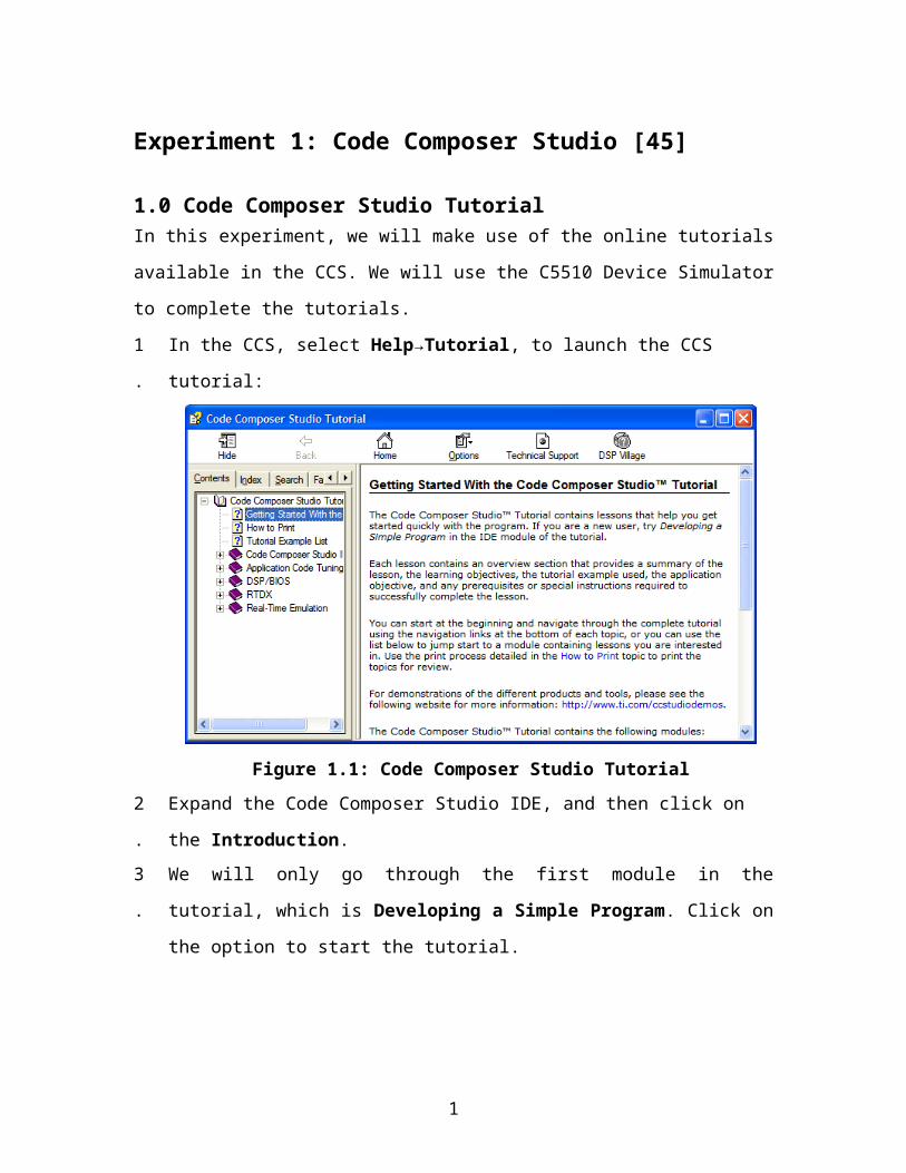
Experiment 1: Code Composer Studio [45]
1.0 Code Composer Studio TutorialIn this experiment, we will make use of the online tutorials available in the CCS. We will
use the C5510 Device Simulator to complete the tutorials.
1. In the CCS, select Help→Tutorial, to launch the CCS tutorial:
Figure 1.1: Code Composer Studio Tutorial
2. Expand the Code Composer Studio IDE, and then click on the Introduction.
3. We will only go through the first module in the tutorial, which is Developing a
Simple Program. Click on the option to start the tutorial.
1
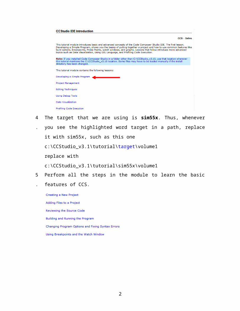
4. The target that we are using is sim55x. Thus, whenever you see the highlighted word
target in a path, replace it with sim55x, such as this one
c:\CCStudio_v3.1\tutorial\target\volume1
replace with
c:\CCStudio_v3.1\tutorial\sim55x\volume1
5. Perform all the steps in the module to learn the basic features of CCS.
6. For the purpose of the experiments, this module should provide sufficient
background information. However, if you are interested in learning more, then you
can complete the Code Composer Studio IDE module on your own. You do not need
the C5510 DSK to perform the experiments in this module.
2
1.1 Exercises [optional]1. From the Option menu, set the CCS for automatically loading the
program after the project has been built.2. After loading the program into the simulator and enabling
Source/ASM mixed display mode from View→Mixed Source/ASM, what is shown in the CCS source display window besides the C source code?
3. What does File→Workspace do? Try the save and reload workspace commands
4. Use the CCS context-sensitive online help menu to find the TMS320C55x CPU diagram, and name all the buses and processing units.
1.3 SummaryIn this experiment, you have learned how to use the Code Composer Studio. In the
following experiments, we will use Code Composer Studio to create real-time DSP
programs and use the C5510 Digital Signal Processing Kit (DSK) to test the performance.
3

Experiment 2: Introduction to C5510 DSK [45]
2.1 The C5510 DSK ReferenceThe TMS320VC5510 DSK Technical Reference contains board components, physical
specifications, and schematics. Software documents are available from CCS help files.
Unfortunately, Texas Instruments has somehow forgotten to integrate the online help on
C5510 DSK into the CCS. The online help file is now put into the \doc folder in the
installation folder. We have extracted the relevant files and put them into the given
RTDSP folder.
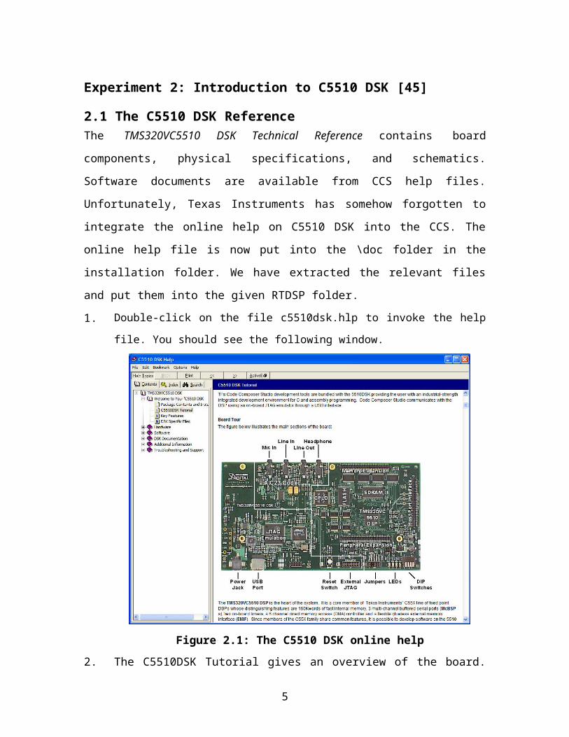
1. Double-click on the file c5510dsk.hlp to invoke the help file. You should see the
following window.
Figure 2.1: The C5510 DSK online help
2. The C5510DSK Tutorial gives an overview of the board. It has a tutorial session
that introduces to you the control of the on board LEDs, DSP/BIOS, a real-time
multitasking kernel designed by Texas Instruments. There is no need of doing the
tutorial. But if you are ahead of the rest in the class, then you go ahead and try it.
You will need the DSK. If it is not available, ask the instructor for it.
4
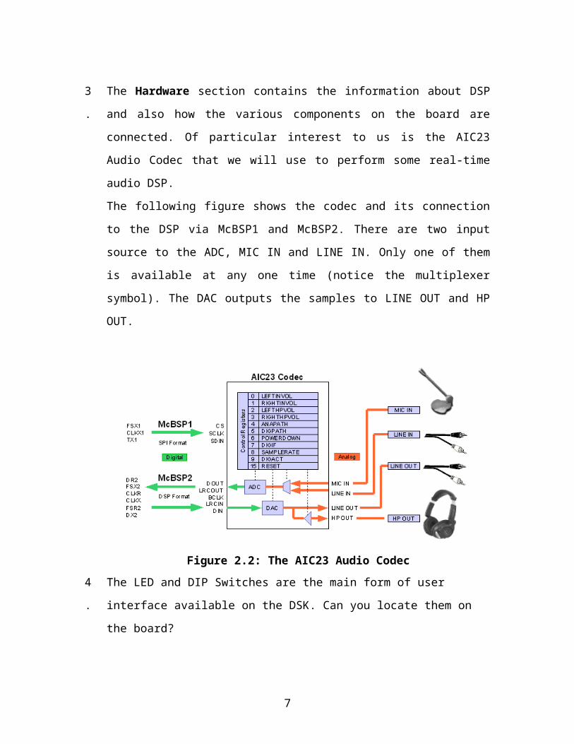
3. The Hardware section contains the information about DSP and also how the various
components on the board are connected. Of particular interest to us is the AIC23
Audio Codec that we will use to perform some real-time audio DSP.
The following figure shows the codec and its connection to the DSP via McBSP1
and McBSP2. There are two input source to the ADC, MIC IN and LINE IN. Only
one of them is available at any one time (notice the multiplexer symbol). The DAC
outputs the samples to LINE OUT and HP OUT.
Figure 2.2: The AIC23 Audio Codec
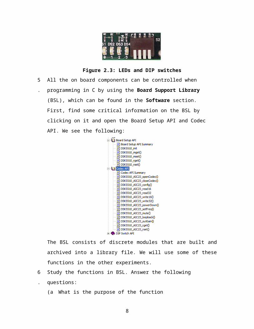
4. The LED and DIP Switches are the main form of user interface available on the
DSK. Can you locate them on the board?
Figure 2.3: LEDs and DIP switches
5. All the on board components can be controlled when programming in C by using the
Board Support Library (BSL), which can be found in the Software section. First,
find some critical information on the BSL by clicking on it and open the Board
Setup API and Codec API. We see the following:
5
The BSL consists of discrete modules that are built and archived into a library file.
We will use some of these functions in the other experiments.
6. Study the functions in BSL. Answer the following questions:
(a) What is the purpose of the function DSK5510_AIC23_config()?
(b) What are the functions that we can use to read audio samples from the ADC?
(c) What are the functions that we can use to write audio samples to the DAC?
(d) Why is there no function that writes to the DIP switches?
(e) Suppose you would like to turn on LED #2. Provide the C statement to
perform the task.
2.2 DSK Examples
The DSK highlights five examples that are designed specifically to work with
components on the DSK board:
The LED example demonstrates the simplest use of the BSL, a function that
blinks a LED and sets another LED based on the value of a DIP switch.
The LEDPRD example shows how to do the same thing using a DSP/BIOS
periodic thread and add a second thread to blink a different LED at a different
rate.
6
The TONE example uses the BSL’s codec functions to generate a sine wave on the
DSK’s audio outputs using polled I/O.
The DSK_APP example is a much more advanced example that uses the DMA to
transfer audio data and several choices of how the DSP processes the data. It is
good example of how codecs and DMA controllers are used in real products and
gets into details of the DSP architecture and peripherals. This example is
recommended for when you are familiar with the DSK and are ready to advance
to the next level.
The POST example is the Power-On Self Test program that the DSK board runs
when the board is reset or powered on. It is a very comprehensive program that
access most of the components on the board.
In addition, you will find in the \examples\5510dsk\bios\audio folder that
there is an AUDIO example, which uses the DSP/BIOS kernel to perform data transfers
and scheduling of processing tasks. It can be used as the template for real-time audio
signal processing. However, we will not discuss DSP/BIOS. Please refer to the online
help for more details.
Let’s try the example tone. This example uses the AIC23 codec module of the 5510
DSK Board Support Library to generate a 1 kHz sinewave on the audio outputs for 5
seconds. The sinewave data is pre-calculated in an array called sinetable. The codec
operates at 48 kHz by default. Since the sinewave table has 48 entries per period, each
pass through the inner loop takes 1 millisecond. 5000 passes through the inner loop takes
5 seconds. Hook up the stereo path cables from the SPEAKERPHONE output on the
DSK to a headphone (or PC loudspeaker). Go through the following steps for running the
tone application that is already installed with the DSK:
1. Open the project (already installed with the C5510 DSK) by selecting Project→ Open. Browse to the already built project tone.pjt located at
c:\CCStudio_v3.1\examples\dsk5510\bsl\tone
2. Select Option→Customize, click on the Program Load Options tab,
and check the Load Program After Build checkbox. This will automatically
7
load the executable code onto DSK after the project is built successfully.
3. Build the project by selecting Project→Rebuild All.4. Run the program by selecting Debug→Run. You should hear a tone playing
through the headphone (or the loudspeaker). Select Debug→Restart can rerun
the program again.
5. Study the C source code tone.c. You may find it useful to step through the code.
Pay special attention to those functions with prefix DSK5510. They are documented
in the online help file. Try to understand how to use them rather than how they are
implemented.
6. Using Edit→Memory command we can manipulate (edit, copy, and fill) system memory of the tone.pjt with the following tasks:(a) Load the program and then place a breakpoint at the
following statement in the tone.c:
for (msec = 0; msec < 5000; msec++)
(b) Run the program. It will stop at the breakpoint.(c) Open the memory window to view sinetable (c) Fill sinetable with 0x0000. The length is 48.(d) Run the program (do not reload, just continue from the
breakpoint).Do you still hear the tone?
2.3 SummaryIn this experiment, you have been introduced to the C5510 DSK and the relevant
reference information. You have also run a sample application that can be used as
template for future experiments. In the next experiment, we will use a more advanced
example to perform real-time FIR filtering.
8
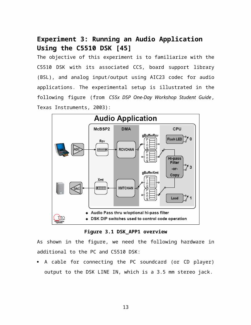
Experiment 3: Running an Audio Application Using the C5510 DSK [45]The objective of this experiment is to familiarize with the C5510 DSK with its associated
CCS, board support library (BSL), and analog input/output using AIC23 codec for audio
applications. The experimental setup is illustrated in the following figure (from C55x
DSP One-Day Workshop Student Guide, Texas Instruments, 2003):
Figure 3.1 DSK_APP1 overview
As shown in the figure, we need the following hardware in additional to the PC and
C5510 DSK:
A cable for connecting the PC soundcard (or CD player) output to the DSK LINE IN,
which is a 3.5 mm stereo jack.
A headphone (or a loudspeaker with power amplifier) that connects to the DSK
HEADPHONE for listen the audio output.
9
3.1 Using DSK_APP1 from C5510 DSK Examples Hook up the stereo path cables from the PC soundcard (or other sound source) output to
the LINE IN input and the headphone (or loudspeaker) to the HEADPHONE output on
the DSK, and make sure that all DSK’s DIP switches are UP. Go through the following
steps for running the audio application that is already installed with the DSK.
1. Open the project (already installed with the C5510 DSK) by selecting
Project→Open. Browse to the already built project dsk_app1.pjt located at
c:\CCStudio_3.1\examples\dsk5510\bsl\dsk_app.
2. Select Option→Customize, click on the Program Load Options tab, and check the
Load Program After Build checkbox. This will automatically load the executable
code onto DSK after the project is built successfully.
3. Build the project by selecting Project → Rebuild All
4. Play some music on the PC (or CD player). Run the program by selecting
Debug→Run. You should hear audio playing through the headphone (or the
loudspeaker).
5. Enable the highpass filter by pressing down DIP switch #3 and notice the change in
the music. The program reads the state of the DIP switch #3 and then runs the FIR
highpass filter when that switch is DOWN, or bypass the filter when the switch is
UP. By turning the switch #3 up and down, we can evaluate the effect of highpass
filter on the music.
3.2 Exercises1. Read the C source code, dsk_app.c to have a higher level understanding. This C
program clearly documents how to use the McBSP and DMA to efficiently handle
the data transfer between the C5510 processor and the AIC23 codec. AIC23
exchanges data serially with the McBSP2 in stereo format (L, R, L, R, …) and
McBSP2 receives/transmits 16-bit data from the codec via DRR/DXR. The software
flow in dsk_app.c starts from initialize DSK board, initialize McBSP/AIC23,
initialize DMA, initialize interrupts, and start DMA. After that the processing tasks
are called by the DSP/BIOS.
How can we change the size of the buffers? Reduce the buffer size to 128 by making
10

the necessary changes and perform a real-time test to verify that the program still
working correctly. What can you observe from the states of the LEDs? Explain the
reason for such observation.
2. The default setting of the codec sampling rate is 48kHz. You can set the desired
sampling frequency using the function DSK5510_AIC23_setFreq() available
in the BSL. For example, we can use the following function to set the sampling rate
to 8kHz:
DSK5510_AIC23_setFreq(hCodec, DSK5510_AIC23_FREQ_8KHZ);
What are the other valid values?
3. Now, modify the C program dsk_app.c by inserting the function that set the
sampling rate to 8kHz. Rebuild the project and perform a real-time testing. The right
place to insert the function call is after the line that starts the codec.
After the program is running, compare the sound effects of sampling rates 8kHz and
48kHz, and explain why such difference is made.
4. Continue from the previous exercise, activate the highpass filter, and explain the
filtering effects of 8kHz and 48kHz. Why the highpass filtering effects is clearer for
the 48kHz sampling rate?
3.3 SummaryIn this experiment, you have run an advanced example that uses the DMA, McBSP and
AIC23 codec to perform data transfer. The example also demonstrates the use of highpass
FIR filter. You have also learned to create new projects based on the given source codes.
You have also experimented with changing the sampling rate of the codec and observed
its effect to the highpass filtering.
11
Experiment 4: Developing Signal Generators in Real Time using the C5510 DSK [60]The objective of this experiment is to use the C5510 DSK with its associated CCS, BSL,
and AIC23 codec for generating sinusoidal and random signals. We will develop our
programs based on the tone project in Experiment 2.
c:\CCSTudio_v3.1\examples\dsk5510\bsl\tone.
4.1 Creating Sinusoidal Signals GeneratorWe have run this sinewave generator on the C5510 DSK in Experiment 2 using the
project tone.pjt located in the folder. In this experiment, we will modify that C
program and build the project using CCS for execution on the C5510 DSK for real-time
experiments. Follow the steps listed below:
1. Follow the instructions in Experiment 2 to load the tone.pjt files.
2. Select Option→Customize, click on the Program Load Options tab, and check
the Load Program After Build checkbox.
3. Build the project by selecting Project→Rebuild All.
4. Connect a headphone (or a loudspeaker) to the HEADPHONE output of C5510
DSK.
5. Run the program by selecting Debug→Run. You should hear a tone playing
through the headphone (or the loudspeaker).
6. Select Debug→Restart to rerun the program again.
12
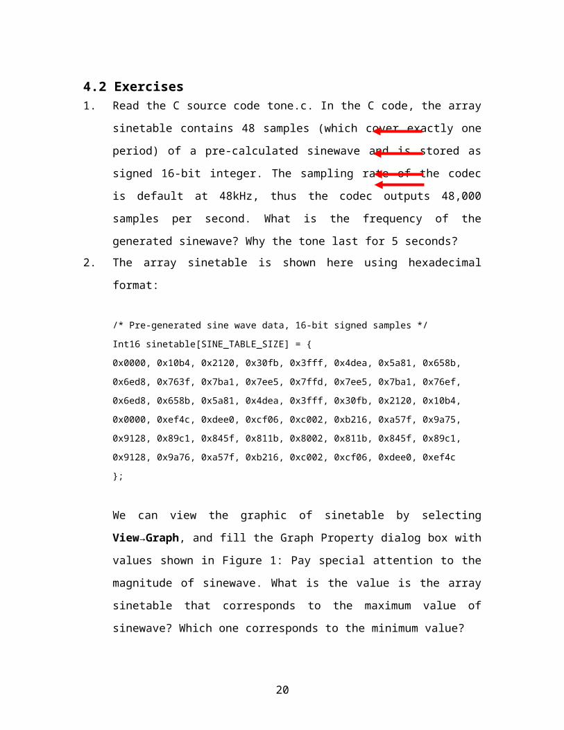
4.2 Exercises1. Read the C source code tone.c. In the C code, the array sinetable contains
48 samples (which cover exactly one period) of a pre-calculated sinewave and is
stored as signed 16-bit integer. The sampling rate of the codec is default at 48kHz,
thus the codec outputs 48,000 samples per second. What is the frequency of the
generated sinewave? Why the tone last for 5 seconds?
2. The array sinetable is shown here using hexadecimal format:
/* Pre-generated sine wave data, 16-bit signed samples */
Int16 sinetable[SINE_TABLE_SIZE] = {
0x0000, 0x10b4, 0x2120, 0x30fb, 0x3fff, 0x4dea, 0x5a81, 0x658b,
0x6ed8, 0x763f, 0x7ba1, 0x7ee5, 0x7ffd, 0x7ee5, 0x7ba1, 0x76ef,
0x6ed8, 0x658b, 0x5a81, 0x4dea, 0x3fff, 0x30fb, 0x2120, 0x10b4,
0x0000, 0xef4c, 0xdee0, 0xcf06, 0xc002, 0xb216, 0xa57f, 0x9a75,
0x9128, 0x89c1, 0x845f, 0x811b, 0x8002, 0x811b, 0x845f, 0x89c1,
0x9128, 0x9a76, 0xa57f, 0xb216, 0xc002, 0xcf06, 0xdee0, 0xef4c
};
We can view the graphic of sinetable by selecting View→Graph, and fill the
Graph Property dialog box with values shown in Figure 1: Pay special attention to
the magnitude of sinewave. What is the value is the array sinetable that
corresponds to the maximum value of sinewave? Which one corresponds to the
minimum value?
13
Figure 4.1: Graph settings for sinewave display
3. The default setting of the codec sampling rate is 48kHz. We can set the desired
sampling frequency using the function DSK5510_AIC23_setFreq(). Modify
the C program tone.c by inserting this line of code to set the sampling rate to
8kHz. Rebuild the program and perform a real-time testing. After the program is
running, compare the sound effects for the sampling rates at 8kHz and 48kHz.
What is the frequency of sinewave that you generated with 8kHz sampling rate?
Why? Also, how many seconds the tone last? Why?
4. Modify the program to generate 1kHz sinewave with 8kHz sampling rate. There
are many ways and two of them are:
(a) You can use the same sinetable with 48 samples, but step through the table
every 6 samples by modifying the outer loops as follows:
for (sample=0; sample<SINE_TABLE_SIZE; sample+=6)
(b) You can recalculate one period of sinewave with 8 samples (using
MATLAB or hand calculation) to replace the original 48 samples sinetable.
In this case, be sure to change the SINE_TABLE_SIZE to 8.
Try both methods. How to make sure that the generated tone is 1kHz with 8kHz
sampling rate?
14
4.3 SummaryIn this experiment, you have used the C5510 DSK with its associated CCS, BSL and
AIC23 codec to generate sinusoidal and random signals. In addition, you have been
shown how to use the DSPLIB functions in your projects.
Experiment 5: FIR Filtering Using the C5510 DSK The objective of this experiment is to further familiarize with the C5510 DSK with its
associated DMA, McBSP, and AIC23 codec. We will also learn an efficient C function
using the C55xx intrinsics for FIR filtering, and use the C compiler optimizer to achieve
highly optimized code by using dual-MAC operation. Experimental setup is illustrated as
follows (from C55x DSP One-Day Workshop Student Guide, Texas Instruments, 2003):
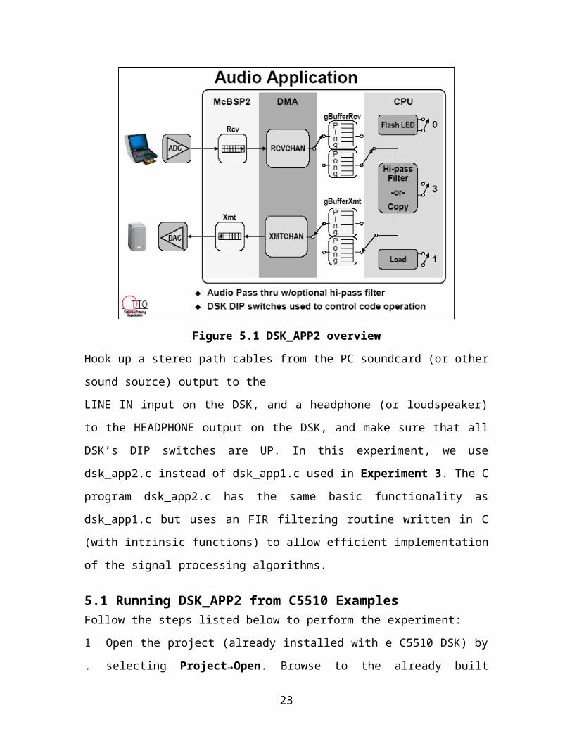
Figure 5.1 DSK_APP2 overview
Hook up a stereo path cables from the PC soundcard (or other sound source) output to the
LINE IN input on the DSK, and a headphone (or loudspeaker) to the HEADPHONE
output on the DSK, and make sure that all DSK’s DIP switches are UP. In this
experiment, we use dsk_app2.c instead of dsk_app1.c used in Experiment 3.
The C program dsk_app2.c has the same basic functionality as dsk_app1.c but
15

uses an FIR filtering routine written in C (with intrinsic functions) to allow efficient
implementation of the signal processing algorithms.
5.1 Running DSK_APP2 from C5510 ExamplesFollow the steps listed below to perform the experiment:
1. Open the project (already installed with e C5510 DSK) by selecting Project→Open.
Browse to the already built project dsk_app2.pjt located at
c:\CCStudio_v3.1\examples\dsk5510\bsl\dsk_app
and then open it.
2. Enable RTDX by selecting Tools→RTDX→Configuration Control and checking
the Enable RTDX checkbox at the bottom right of CCS window. RDTX is a
communication protocol that allows your program to communicate with CCS
through the embedded USB emulator. The settings are set for non-continuous mode
with a buffer size of 1024. You can close this window by right clicking on the grey
window (shown below) area and selecting close.
Figure 5.2: RTDC Control Window
3. Enable the CPU load plug-in by selecting DSP/BIOS→CPU Load Graph. The load
graph will appear at the bottom of CCS window as below:
Figure 5.3: CPU load graph
4. Load the executable file dsk_app2.out by selecting File→Load Program. It will
open a file browser dialog. Select the file dsk_app2.out in the dsk_app\Debug
directory and hit Open to load the executable.
16
5. Play some music on the PC (or MP3 player) and connect the output to the DSK
LINE IN input. Run the program by selecting Debug→Run. You should hear audio
playing through the headphone (or the loudspeaker). You will see LED #2 and LED
#3 blinking. They toggle every time a ping or pong buffer is received. You will also
see a display on the CPU load graph indicating what percentage of the total cycles is
spent doing real work. It should be well under 10% as shown below (the left portion
of the green curve).
Figure 5.4: CPU load graph when running aplication
6. Enable the highpass filter by pressing down DIP switch #3 and notice the change in
the music, why? The program reads the state of the DIP switch #3 and then runs the
FIR highpass filter when that switch is DOWN, or bypass the filter when that switch
is UP. By turning the switch #3 up and down, you can evaluate the effect of highpass
filter on the music.
You also will see the CPU load go up accordingly (see the middle portion of green
curve). What percentage of CPU load is used to run two 208-tap FIR highpass filters
(for the left and right channels) at 48 kHz? For most communication applications,
sampling rate is 8 kHz, what percentage of CPU load is needed for a single 208-tap
FIR filtering?
7. Finally, press down DIP switch #1. This will enable a 20-25% dummy CPU load
that represents other computation the DSP processor may be doing. You will see the
CPU load go up by a substantial amount (see the right portion of green curve).
8. We can plot the impulse response (filter coefficients) of the 208-tap FIR filter by
selecting View→Graph→Time/Frequency, and entering the following
parameters in Graph Property Dialog box:
17

Figure 5.5: Graph settings to plot filter’s impulse response
Note that the FIR filter coefficient array is defined as COEFFS in the included file
highpass.h. The impulse response (length 208) of this symmetric FIR filter is
displayed as follows:
Figure 5.6: Filter impulse response
18

9. You also can evaluate the magnitude response of this highpass filter by filling the
Graph Property Dialog box as follows:
Figure 5.7: Graph settings to plot filter’s frequency response
Figure 5.8: Frequency response of the highpass FIR filter
10. Right click on the graph and then select Log scale. What is the cutoff frequency of
the highpass filter? We will design FIR filters for experiments in Experiment 6
using the FDATool in MATLAB.
19
5.2 Appendix: Block Processing with dual-MAC Block processing assumes we have a block of input samples, and FIR filtering is
performed to generate output samples. In this case, we have at least two signal
samples; thus we can compute two sequential filtering operations in parallel. For
example, we can compute the following two equations in parallel using the dual_MAC
units.
One MAC unit computes while the other MAC unit computes . Since
the filter coefficient is common to both MAC units, these two computations require
only three different values form memory: , , and . Thus the multiplication
process can be implemented effectively using the dual MAC units on the C55x as shown
in the following figure.
Simplified dual-MAC architecture on the C55x
20

Experiment 6: Design and Implementation of FIR Filters Using the FDATool and the C5510 DSK [60]The objectives of this experiment are to design FIR filters using the FDATool in
MATLAB (version 7.0 and above) Signal Processing Toolbox, and to implement the
designed filters using the C5510 DSK for real-time experiments. Experimental setup is
same as the Experiment 3 and Experiment 5 as illustrated below (from C55x DSP One-
Day Workshop Student Guide, Texas Instruments, 2003):
Figure 6.1 DSK_APP2 overview
Connect a stereo cable from the PC soundcard (or other sound source) output to the LINE
IN input on the DSK, and a headphone (or loudspeaker) to the HEADPHONE output on
the DSK, and make sure that four DIP switches are UP. In this experiment, we will
modify the C program dsk_app2.c, which was used in previous experiment and we
will design an FIR lowpass filter using MATLAB FDATool.
21
6.1 Filter Design Using FDAToolIn this experiment, we will use the FDATool for designing FIR lowpass and highpass
filters. Go through the following steps for designing a lowpass FIR filter:
1. Launch MATLAB. Once you are in the MATLAB command window, type
fdatool and press Enter.
2. In the Filter Design & Analysis Tool window, design an FIR filter with sampling
rate 48kHz, the passband frequency is 2kHz, stopband frequency is 2.5kHz, and the
stopband attenuation is 60dB. These specifications can be entered as shown in the
figure below. Click the Apply button to design the filter. You should get the same
frequency response as shown here. The filter length is 191 (order is length plus one).
Figure 1 : FIR Lowpass filter designed using FDATool
22
Set Quantization Parameters
3. Click on the Set Quantization Parameters icon (refer to the figure in Step 2). From
the Filter Arithmetic box, select Fixed-point and click on the Coefficients tab.
Check on Scale the numerator coefficients to fully utilize the entire dynamic
range, and then click on Apply. Notice that in the Current Filter Information
panel, the Source field shows that the filter coefficients have been quantized.
Figure 2: Quantizing the filter coefficients to fixed-point
4. Select Target→Generate C header in the menu to export the filter coefficients to a
C header file. For consistent with the C source code in dsk_app2.c, enter COEFFS in
the Numerator box, and ORDER in the Numerator length box. Click Apply and save
the C header file as lowpass.h into your working folder for this experiment.
23
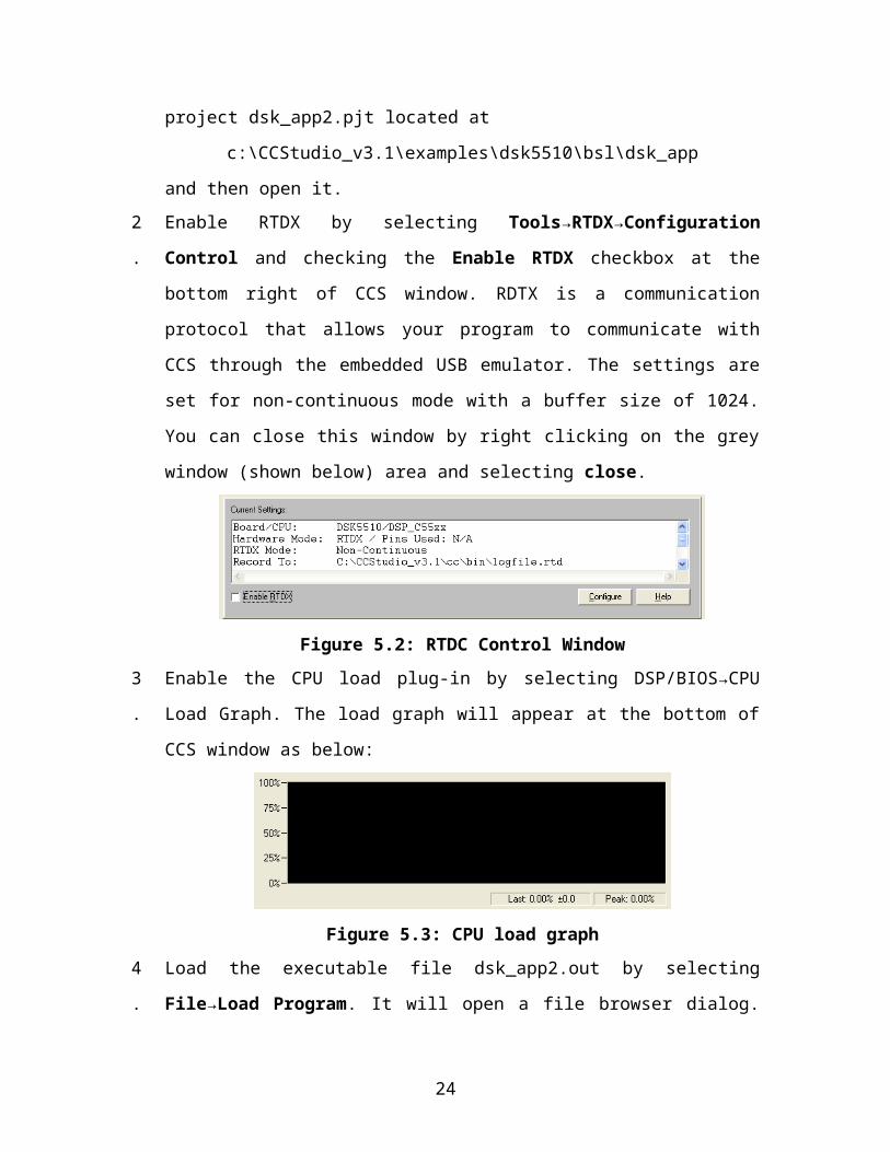
Figure 3: Export coefficients as C header file
5. Open the saved coefficient header file lowpass.h and make three minor changes:
(a) comment out #include “tmwtypes.h”
(b) comment out const int ORDER=191;
(c) define the COEFFS array as Int16 instead of const int16_T
Figure 4: Changing the generated C header file lowpass.h
24
a
b
c

6.2 Real-Time Implementation of FIR Lowpass FilterWe have designed the lowpass FIR filter using the FDATool, saved the coefficients in the C
header file lowpass.h, and modified it to fit the C main program. The next step is to
modify dsk_app2.c that implements this new filter for real-time experiments on the
C5510 DSK.
1. Add the required files into the project .
2. We have to modify dsk_app2.c for the experiment. From the Project View
window, expand the project dsk_firLPF.pjt and then double-click on
dsk_app2.c to open it.
First we modify the C statement
#include “highpass.h”
to the following statement:
#include “lowpass.h”
This is because we want to use the new lowpass filter coefficients to perform the
filtering. We then replace the filter order 208 with 191 as follows:
#define ORDER 191
Save the changes by selecting File→Save All.
3. After you have successfully rebuilt the project, run the executable by selecting
Debug→Run. Play some music on the PC (or MP3 player) and connect the output
to the DSK LINE IN input.
5. Enable the lowpass filter by pressing down DIP switch #3 and notice the change in
the music, why? The program reads the state of the DIP switch #3 and then runs the
FIR lowpass filter when that switch is DOWN, or bypass the filter when the switch
is UP. By turning the switch #3 up and down, you can evaluate the effects of
lowpass filter on the music. Can you tell the difference with the sound effects that
you heard in Experiment 5?
6.3 Exercises1. Plot the impulse response of the lowpass filter we have designed using the CCS
Graph. Create another graph to show the frequency response of the filter.
25

Compare the result with the filter frequency response shown in MATLAB
FDATool window.
6.4 SummaryIn this experiment, you have learned to design filters using the MATLAB’s FDATool.
You have also modified the template program to implement the designed filters in real-
time on the C5510 DSK. You should have the basic knowledge required to implement
various filtering-based applications real-time application on the DSK.
26