
EXPANSION JOINTS: RUBBER, TEFLON 1 - … design. This consideration is to ensure the correct balance...
52
EXPANSION JOINTS: RUBBER, TEFLON ® STAINLESS Product Guide 03
Transcript of EXPANSION JOINTS: RUBBER, TEFLON 1 - … design. This consideration is to ensure the correct balance...

1EXPANSION JOINTS:
RUBBER, TEFLON ®
STAINLESSP r o d u c t G u i d e
0 3

EXP
AN
SIO
N J
OIN
TS1
23
45
2
Pacific Hoseflex COMPANY PROFILE
3.02
2
Pacific Hoseflex (PHF) has been operating out of South East Queensland for over 15 years. This Australian owned and family business was started by Tony and Tina Gray in the early 1990’s. Utilizing diverse backgrounds in engineering and 30 years experience, PHF embarked on a venture that has evolved into an extremely successful and still growing business.
Pacific Hoseflex ‘s management and staff have diversified their engineering skills to hose products, hose fittings and expansion joints which are distributed both nationally and internationally. Our products can be found in the most diverse industries and applications; renewable energy, desalination, hydrocarbon, water, underground mines, automotive, power stations, marinas, food and chemical industries, steel works, instrumentation equipment, armed forces and an almost endless number of fluid and air conveyance applications.
We have progressively incorporated quality and seamless procedures and manufacturing practices in concert with our valuable staff to achieve an all encompassing Quality Management System.
We have been assessed for quality assurance and are certified to ISO 9001:2000. As well a number of major national and international clients have independently audited and endorsed our quality system. We are AGA approved and all welding is completed to Standard AS 4041 (Class 1).
Pacific Hoseflex has always focused on training and we are absolutely committed to safety. We have successfully nurtured many apprentices, up skilled tradesmen and developed a broad range of staff over the years.
For further information contact our sales team on:http://www.hoseflex.com.au
Machining Team
Hose Assembling Team
Accounts
From left: Chris, Glen, Craig and Tom
From left: Peter, Tim, Brett, Corey, Rich, Bob, Sam, Josh and Luke
From left: Karley, Tina and Emily
Sales
From left: Jason, Ben, Andrew, Tony, Andrew, Sean and Sue

EXP
AN
SIO
N J
OIN
TS1
23
45
3
PRODUCT RANGE3.03
3
Teflon Hose
Expansion Joints:RubberTeflonStainless
01
03
Stainless Steel Interlock HoseStainless Steel Hose 02
04Composite HoseDucting HoseRubber Hose
05 Fittings
®
®
Complete Range of Pacific Hoseflex

EXP
AN
SIO
N J
OIN
TS1
23
45
EXPANSION JOINTS
4
The Range
(SEJ) Single Expansion Joint Page 3.09
(UEJ) Universal Expansion Joint Page 3.11
(DEJ) Diesel Expansion Joint Page 3.12
(DDEJ) Double Diesel Expansion Joint Page 3.13
(DMEJ) Diesel Multiply Expansion Joint Page 3.14
(DAEJ) Double Axial Expansion Joint Page 3.15
(HEJ) Single Hinged Expansion Joint Page 3.16
(DHEJ) Double Hinged Expansion Joint Page 3.17
(GEJ) Single Gimbal Expansion Joint Page 3.18
(DGEJ) Double Gimbal Expansion Joint Page 3.19
(XT) Externally Pressurised Expansion Joint Page 3.21
(DXT) Double Externally Pressurised Expansion Joint Page 3.23
(TEJ) Single Tied Expansion Joint Page 3.25
(DTEJ) Double Tied Expansion Joint Page 3.26
Seismic Joint Page 3.28
Expansion Loops Page 3.29
(PEJ2) PTFE Expansion Joints 2 Convolutions Page 3.31
(PEJ3) PTFE Expansion Joints 3 Convolutions Page 3.32
(PEJ5) PTFE Expansion Joints 5 Convolutions Page 3.33
(REJ) Rubber Expansion Joint Single Sphere Page 3.34
(TREJ) Rubber Expansion Joint Twin Sphere Page 3.36
(FEJ) Fabric Expansion Joints Page 3.37
3.04
4
EXP
AN
SIO
N J
OIN
TS1
23
45
EXPANSION JOINTS
5
3.05 Metallic Expansion Joints
Introduction
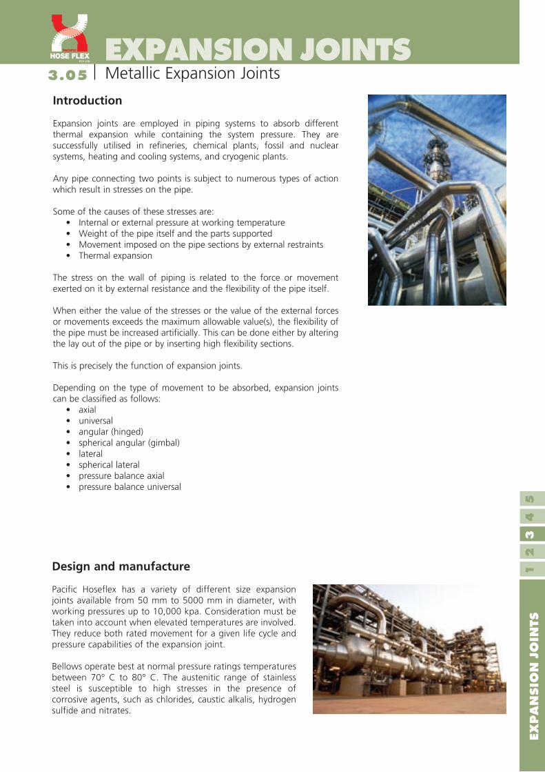
Expansion joints are employed in piping systems to absorb different thermal expansion while containing the system pressure. They are successfully utilised in refineries, chemical plants, fossil and nuclear systems, heating and cooling systems, and cryogenic plants.
Any pipe connecting two points is subject to numerous types of action which result in stresses on the pipe.
Some of the causes of these stresses are:• Internal or external pressure at working temperature• Weight of the pipe itself and the parts supported• Movement imposed on the pipe sections by external restraints• Thermal expansion
The stress on the wall of piping is related to the force or movement exerted on it by external resistance and the flexibility of the pipe itself.
When either the value of the stresses or the value of the external forces or movements exceeds the maximum allowable value(s), the flexibility of the pipe must be increased artificially. This can be done either by altering the lay out of the pipe or by inserting high flexibility sections.
This is precisely the function of expansion joints.
Depending on the type of movement to be absorbed, expansion joints can be classified as follows:
• axial• universal• angular (hinged)• spherical angular (gimbal)• lateral• spherical lateral• pressure balance axial• pressure balance universal
Design and manufacture
Pacific Hoseflex has a variety of different size expansion joints available from 50 mm to 5000 mm in diameter, with working pressures up to 10,000 kpa. Consideration must be taken into account when elevated temperatures are involved. They reduce both rated movement for a given life cycle and pressure capabilities of the expansion joint.
Bellows operate best at normal pressure ratings temperatures between 70° C to 80° C. The austenitic range of stainless steel is susceptible to high stresses in the presence of corrosive agents, such as chlorides, caustic alkalis, hydrogen sulfide and nitrates.

EXP
AN
SIO
N J
OIN
TS1
23
45
EXPANSION JOINTS
6
Definition of Movement3.06
Axial Movement Lateral Movement Angular Movement
Axial Compression is the dimensional shortening of an Expansion Joint along its longitudinal axis while axial extension is the dimensional lengthening of the expansion joint.
Lateral Deflection is the relative displacement of the two ends of an Expansion Joint perpendicular to its longitudinal axis.
Angular Rotation is the displacement of the longitudinal axis of the Expansion Joint from its initial straight line position into a circular arc.
Cycle Life
This the anticipated number of complete expansions and contractions that a bellow can accommodate in its working life, this is an important consideration with bellow design. This consideration is to ensure the correct balance between the pressure containing characteristics and the movement.
The cycle life expectancy of an expansion joint is affected by the flowing various factors;
• operating pressure• operating temperature• the material from which the bellows is made• the movement per convolution• the thickness of the bellow• the convolution pitch • depth and shape of convolution
After installation any change to any of these factors will impact upon the cycle life.
Quality Management
We have progressively incorporated quality and seamless procedures and manufacturing practices in concert with our valuable staff to achieve an all encompassing Quality Management System - with accredited Quality Assurance, ISO 9001:2000.
Pacific Hoseflex quality control measures - inspection and testing procedures include; inwards goods inspection, in process inspection, final product release inspection and leak detection inspection. There are several different methods for leak detection; dye penetrate examination, x-ray examinations, magnetic particle inspection, hydrostatic test and pneumatic test.

EXP
AN
SIO
N J
OIN
TS1
23
45
EXPANSION JOINTS
7
Bellow Forming & Material3.07
Bellow forming
The basic method(s) of bellows manufacture is not complicated. There are two ways that a bellows can be manufactured:
1. Mechanical forming can be done by either rolling the convolutions between external and internal wheels.
2. Hydraulic forming, using internal pressure has a much greater life than bellows formed by the other method(s). Bellows shall be hydraulically formed from a tube having only longitudinal seams. When the ratio of corrugation diameter to shell diameter is large, as in small diameter bellows, the units shall be annealed to remove stresses created by the forming operation.
The number of convolutions depends upon the amount of movement the bellow must accommodate or the force that must be used to accomplish the deflection. Since bellows are unique, there are many design considerations which must be evaluated. The convoluted element must be strong enough circumferentially to withstand the line pressure of the system, yet responsive enough longitudinally to flex. The longitudinal load (pressure thrust) must then be absorbed by some other type of device. These are usually anchors, tie rods, hinges or gimbal structures.
Under pressure a bellow will crave to squirm. This can occur when a bellow is subjected to a pressure greater than 1.5 times the design pressure. Squirm can be considered the same as column buckling in a beam under compressive loading. The convolutions deform and even though there is no leaking, both cycle life and pressure capacity is greatly reduced.
Bellow material
Stainless Steel 304Is a lower grade material than 321 SS with less resistance to corrosion. Applications include diesel engine exhaust manifolds and steam.
Stainless Steel 321The most common material used for bellow manufacture. It combines excellent mechanical properties with adequate corrosion resistance. Applications include diesel engine exhaust manifolds and steam.
Stainless Steel 316Has a better corrosion resistance than 321 SS and can be used as an alternative to Incoloy 825. Applications include engine exhaust manifolds, steam and marine services.
Incoloy 825, 800A high nickel alloy specifically designed for use in aggressive environment. It is very resistant to pitting and crevice corrosion and virtually immune to stress corrosion cracking. It can be used up to a maximum temperature of 425° C. Applications include diesel engine exhaust manifolds, steam, crude oil lines and flue gases.
Inconel 625, 600 and 800Is a high nickel ally with good corrosion resistant and temperature capability higher than 425° C.
Nickel 200, 253 MAThis alloy has good mechanical properties and excellent corrosion resistance to alkalis, i.e. sodium hydroxide. It also has good electrical, thermal and magneto-strictive properties. Applications include food and synthetic fibre processing, heat exchangers, chemical and electrical industries.

EXP
AN
SIO
N J
OIN
TS1
23
45
EXPANSION JOINTS
8
Hastelloy It has a high-strength, nickel based, corrosion resistant alloy. Other components include molybdenum and chromium. It is well suited for most chemical applications. It has excellent resistance to pitting, stress-corrosion and cracking
254 SMOThis is a very high end austenitic stainless steel that combines impact toughness resistance to chloride stress corrosion cracking, pitting and crevice corrosion with strength nearly twice that of 300 series stainless steels. In some applications it has been found to be a more cost effective substitute for high nickel and titanium alloys.
Bellow Material3.08
Accessories
Limiting RodsLimiting Rods are used to limit movement to the design capability. In the event of an anchor failure, the rods will absorb the full pressure thrust loading of the expansion joint.
Liners Liners are used to prevent flow induced vibration or erosion caused by abrasive materials. When lateral movement is required in the expansion joint, the flow liner diameter must be reduced to provide clearance.
Tie Rods Tie Rods are used to restrain the thrust forces created by the internal pressure of the expansion joint. Normally the system anchors are used to withstand the pressure thrust forces.
Telescopic LinersTelescoping liners are used on short expansion joints with large axial movements. When fit close together, they can also be used in systems where the flow can be in either direction.
Control Rods Control Rods are devises that limit the individual travel of each bellows in a universal or dual expansion joint. These rods can also be designed to support external loads. Control rods are not normally designed to absorb the pressure thrust loads.

EXP
AN
SIO
N J
OIN
TS1
23
45
EXPANSION JOINTS
9
Metallic Expansion Joint3.09
9
• Used for absorbing axial, angular and small amounts of lateral movement.
• Standard assemblies with flanges, weld ends or a combination of both.
• Pressure thrust will be transmitted onto the pipeline.• Correct anchoring and guiding must be used.• Standard working pressures are 240, 700 and 1400 kPa.• Pressures up to 10,000 kPa available on request.• Standard diameters up to 5000 mm available on request.
Single Expansion Joint (SEJ)
*Non–concurrent
50 SEJ-240 50 145 218 32 12 18 21 1
50 SEJ-700 50 145 218 21 8 18 21 3
50 SEJ-1400 50 145 218 18 7 18 70 6
65 SEJ-240 65 180 234 36 12 18 19 2
65 SEJ-700 65 180 234 28 11 18 57 4
65 SEJ-1400 65 180 234 22 7 18 102 9
80 SEJ-240 80 180 278 34 13 18 12 2
80 SEJ-700 80 180 278 34 13 18 36 6
80 SEJ-1400 80 180 278 25 8 17 130 12
100 SEJ-240 100 190 278 36 13 18 47 3
100 SEJ-700 100 190 278 32 10 18 84 9
100 SEJ-1400 100 190 278 27 7 14 169 19
125 SEJ-240 125 215 313 50 13 18 50 4
125 SEJ-700 125 215 313 37 10 18 87 14
125 SEJ-1400 125 215 313 27 7 14 169 27
150 SEJ-240 150 215 338 50 15 18 50 6
150 SEJ-700 150 215 338 39 9 18 72 19
150 SEJ-1400 150 215 338 26 6 14 330 39
200 SEJ-240 200 225 330 57 16 18 28 11
200 SEJ-700 200 225 330 47 9 17 105 33
200 SEJ-1400 200 225 330 30 6 13 541 66
250 SEJ-240 250 245 341 64 17 18 27 17
250 SEJ-700 250 245 341 62 10 18 120 51
250 SEJ-1400 250 245 341 44 8 13 289 102
300 SEJ-240 300 280 400 76 18 18 28 24
300 SEJ-700 300 280 400 68 12 17 119 70
300 SEJ-1400 300 280 400 43 8 13 290 141
350 SEJ-240 350 270 418 88 15 18 59 29
350 SEJ-700 350 270 418 69 10 15 126 85
350 SEJ-1400 350 270 418 43 6 12 711 170
400 SEJ-240 400 270 418 84 10 17 86 37
400 SEJ-700 400 270 418 49 5 12 433 108
400 SEJ-1400 400 270 418 35 4 10 1013 217
450 SEJ-240 450 270 436 83 8 15 97 46
450 SEJ-700 450 270 436 48 5 11 490 135
450 SEJ-1400 450 270 436 36 4 8 1136 170
500 SEJ-240 500 270 436 92 9 14 74 57
PART NO NOM LENGTH MOVEMENTS* SPRING PRESS
BORE FF WW AXIAL LATERAL ANGULAR RATE THRUST
MM MM MM MM MM DEG N/MM KN

EXP
AN
SIO
N J
OIN
TS1
23
45
EXPANSION JOINTS
10
Metallic Expansion Joint3.10
10
*Non–concurrent
500 SEJ-700 500 270 436 58 6 12 375 167
500 SEJ-1400 500 270 436 39 4 8 1268 335
600 SEJ-240 600 290 450 88 8 12 90 80
600 SEJ-700 600 290 450 58 5 10 459 235
600 SEJ-1400 600 290 450 39 3 7 1541 470
650 SEJ-240 650 395 490 105 15 17 92 93
650 SEJ-700 650 395 490 62 10 13 441 271
650 SEJ-1400 650 395 490 58 9 10 1126 542
700 SEJ-240 700 395 490 103 15 17 131 107
700 SEJ-700 700 395 490 61 10 13 463 312
700 SEJ-1400 700 395 490 58 9 10 1322 624
750 SEJ-240 750 395 490 114 13 16 89 124
750 SEJ-700 750 395 490 69 9 12 498 362
750 SEJ-1400 750 395 490 65 8 11 1438 724
800 SEJ-240 800 395 490 116 13 14 98 140
800 SEJ-700 800 395 490 70 8 10 672 408
850 SEJ-240 850 395 490 110 11 13 107 156
850 SEJ-700 850 395 490 70 7 9 1291 455
900 SEJ-240 900 430 500 108 10 12 115 174
900 SEJ-700 900 430 500 67 6 8 1332 508
950 SEJ-240 950 430 500 110 11 13 122 196
950 SEJ-700 950 430 500 68 7 9 1406 572
1000 SEJ-240 1000 395 490 102 8 11 101 214
1000 SEJ-700 1000 395 490 57 4 6 1510 624
1050 SEJ-240 1050 300 480 94 6 8 106 231
1050 SEJ-700 1050 300 480 44 3 5 2376 673
1100 SEJ-240 1100 300 480 96 6 8 142 260
1150 SEJ-240 1150 300 480 94 6 7 159 279
1200 SEJ-240 1200 300 480 92 5 8 264 304
1250 SEJ-240 1250 300 480 90 5 7 317 333
1300 SEJ-240 1300 470 550 122 11 8 342 359
1350 SEJ-240 1350 470 550 118 11 8 369 386
1400 SEJ-240 1400 470 550 118 10 8 392 414
1450 SEJ-240 1450 470 550 110 10 8 421 443
1500 SEJ-240 1500 470 550 110 8 7 448 473
PART NO NOM LENGTH MOVEMENTS* SPRING PRESS
BORE FF WW AXIAL LATERAL ANGULAR RATE THRUST
MM MM MM MM MM DEG N/MM KN

EXP
AN
SIO
N J
OIN
TS1
23
45
EXPANSION JOINTS
11
Metallic Expansion Joint3.11
11
• Used for absorbing large amounts of axial, angular and lateral movement in low pressure pipelines.
• Standard assemblies with flanges, weld ends or a combination of both.
• Pressure thrust will be transmitted onto the pipeline.• Correct anchoring and guiding must be used.• Standard working pressures are 100 and 200 kPa
depending on diameter. • Standard diameters up to 5000 mm available on request.
Universal Expansion Joint (UEJ)
*Non–concurrent
50 UEJ-200 50 380 460 64 76 18 11 0.8
65 UEJ-200 65 380 460 64 76 18 10 1.4
80 UEJ-200 80 380 460 70 76 18 6 1.8
100 UEJ-200 100 430 526 72 76 18 24 2.8
125 UEJ-200 125 430 526 106 130 18 25 4.0
150 UEJ-200 150 430 576 106 120 18 21 5.6
200 UEJ-200 200 450 560 114 98 18 14 9.4
250 UEJ-200 250 485 582 112 98 18 14 14.8
300 UEJ-200 300 555 700 152 114 18 14 20
350 UEJ-200 350 540 736 178 114 18 30 24
400 UEJ-200 400 540 736 178 114 18 43 30
450 UEJ-200 450 540 772 182 102 18 49 38
500 UEJ-200 500 540 772 182 102 16 37 46
600 UEJ-200 600 540 772 148 86 16 45 66
650 UEJ-200 650 690 790 108 72 15 72 76
700 UEJ-100 700 690 790 111 72 15 82 43
750 UEJ-100 750 690 790 119 70 15 71 50
800 UEJ-100 800 690 790 122 64 15 74 58
850 UEJ-100 850 690 790 112 60 15 79 64
900 UEJ-100 900 690 790 112 59 15 87 71
950 UEJ-100 950 690 790 120 57 15 93 79
1000 UEJ-100 1000 1190 1290 120 54 14 121 85
1050 UEJ-100 1050 1190 1290 78 68 14 127 96
1100 UEJ-100 1100 1190 1290 78 61 14 137 116
1150 UEJ-100 1150 1190 1290 74 63 12 262 125
1200 UEJ-100 1200 1190 1290 84 64 10 209 131
1250 UEJ-100 1250 1290 1380 122 82 12 332 143
1300 UEJ-100 1300 1290 1380 122 82 12 348 155
1350 UEJ-100 1350 1290 1380 120 81 12 362 167
1400 UEJ-100 1400 1290 1380 120 75 12 376 179
1450 UEJ-100 1450 1290 1380 120 73 15 389 183
1500 UEJ-100 1500 1290 1380 118 70 15 398 202
PART NO NOM LENGTH MOVEMENTS* SPRING PRESS
BORE FF WW AXIAL LATERAL ANGULAR RATE THRUST
MM MM MM MM MM DEG N/MM KN

3.12
EXP
AN
SIO
N J
OIN
TS1
23
45
EXPANSION JOINTS
12
Metallic Expansion Joint
• Used for absorbing thermal expansion in exhaust, gas ducting and low pressure systems.
• Standard assemblies with flanges, weld ends or a combination of both.
• Pressure thrust will be transmitted onto pipeline.• Correct anchoring and guiding must be used.• Internal flow liners for eliminating velocity and flow problems
fitted as standard.• Standard working pressure is 100 kPa standard diameters up
to 5000 mm available on request.
Diesel Expansion Joint (DEJ)
12
50 DEJ–100 50 145 218 36 12 18 21 0.4
65 DEJ–100 65 180 234 39 12 18 19 0.7
80 DEJ–100 80 180 240 44 13 18 12 0.9
100 DEJ–100 100 190 278 44 13 18 47 1.4
125 DEJ–100 125 215 313 50 13 18 50 2.0
150 DEJ–100 150 215 338 54 15 18 42 2.8
200 DEJ–100 200 225 330 59 16 18 28 4.7
250 DEJ–100 250 245 341 70 17 18 27 7.4
300 DEJ–100 300 280 400 82 18 18 28 10
350 DEJ–100 350 270 418 89 15 18 59 12
400 DEJ–100 400 270 418 96 10 17 86 15
450 DEJ–100 450 270 436 96 8 15 97 19
500 DEJ–100 500 270 436 98 9 14 74 23
600 DEJ–100 600 270 436 96 7 12 90 33
650 DEJ–100 650 385 460 107 12 15 76 38
700 DEJ–100 700 385 460 107 12 15 81 43
750 DEJ–100 750 385 460 107 12 15 65 50
800 DEJ–100 800 385 460 104 11 15 71 58
850 DEJ–100 850 385 460 104 11 14 73 64
900 DEJ–100 900 385 460 100 10 14 81 71
950 DEJ–100 950 385 460 100 9 12 84 79
1000 DEJ–100 1000 330 415 96 6 10 108 85
1050 DEJ–100 1050 330 415 96 6 10 109 96
1100 DEJ–100 1100 330 415 96 5 9 113 116
1150 DEJ–100 1150 305 415 94 5 9 138 125
1200 DEJ–100 1200 330 415 94 8 9 171 131
1250 DEJ–100 1250 480 590 127 11 10 343 143
1300 DEJ–100 1300 480 590 127 11 10 351 155
1350 DEJ–100 1350 480 590 124 10 9 362 167
1400 DEJ–100 1400 480 590 124 10 9 377 179
1450 DEJ–100 1450 480 590 120 9 8 385 183
1500 DEJ–100 1500 480 590 120 9 8 396 202
PART NO NOM LENGTH MOVEMENTS* SPRING PRESS
BORE FF WW AXIAL LATERAL ANGULAR RATE THRUST
MM MM MM MM MM DEG N/MM KN
*Non–concurrent

3.13
EXP
AN
SIO
N J
OIN
TS1
23
45
EXPANSION JOINTS
13
Metallic Expansion Joint
13
• Used for absorbing large amounts of axial angular and lateral movements in low pressure pipelines.
• Standard assemblies with flanges, weld ends or a combination of both.
• Pressure thrust will be transmitted onto pipeline.• Correct anchoring and guiding must be used.• Internal flow liners for eliminating velocity & flow problems fitted as
standard.• Standard working pressure is 100 kPa.• Standard diameters up to 5000 mm are available on request.
Double Diesel Expansion Joint (DDEJ)
50 DDEJ–100 50 380 460 64 76 18 11 0.4
65 DDEJ–100 65 380 460 64 76 18 16 0.7
80 DDEJ–100 80 380 460 70 76 18 6 0.9
100 DDEJ–100 100 430 526 72 76 18 24 1.4
125 DDEJ–100 125 430 526 106 130 18 25 2.0
150 DDEJ–100 150 430 576 106 120 18 21 2.8
200 DDEJ–100 200 450 560 114 98 18 14 4.7
250 DDEJ–100 250 485 582 112 98 18 14 7.4
300 DDEJ–100 300 555 700 152 114 18 14 10
350 DDEJ–100 350 540 736 178 114 18 30 12
400 DDEJ–100 400 540 736 178 114 18 43 15
450 DDEJ–100 450 540 772 182 102 18 49 19
500 DDEJ–100 500 540 772 182 102 16 37 23
600 DDEJ–100 600 540 854 148 86 16 45 33
650 DDEJ–100 650 690 790 108 72 15 72 38
700 DDEJ–100 700 690 790 111 72 15 82 43
750 DDEJ–100 750 690 790 119 70 15 71 50
800 DDEJ–100 800 690 790 122 64 15 74 58
850 DDEJ–100 850 690 790 112 60 15 79 64
900 DDEJ–100 900 690 790 112 59 15 87 71
950 DDEJ–100 950 690 790 120 57 15 93 79
1000 DDEJ–100 1000 1190 1290 120 54 14 121 85
1050 DDEJ–100 1050 1190 1290 78 68 14 127 96
1100 DDEJ–100 1100 1190 1290 78 61 14 137 116
1150 DDEJ–100 1150 1190 1290 74 63 12 262 125
1200 DDEJ–100 1200 1190 1290 84 64 10 209 131
1250 DDEJ–100 1250 1290 1380 122 82 12 332 143
1300 DDEJ–100 1300 1290 1380 122 82 12 348 155
1350 DDEJ–100 1350 1290 1380 120 81 12 362 167
1400 DDEJ–100 1400 1290 1380 120 75 12 376 179
1450 DDEJ–100 1450 1290 1380 120 73 15 389 183
1500 DDEJ–100 1500 1290 1380 118 70 15 398 202
PART NO NOM LENGTH MOVEMENTS* SPRING PRESS
BORE FF WW AXIAL LATERAL ANGULAR RATE THRUST
MM MM MM MM MM DEG N/MM KN
*Non–concurrent
3.14
EXP
AN
SIO
N J
OIN
TS1
23
45
EXPANSION JOINTS
14
Metallic Expansion Joint
14
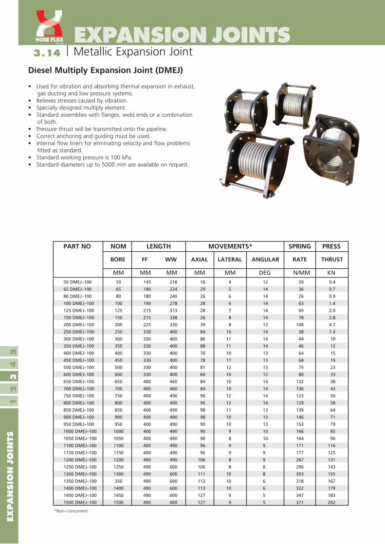
• Used for vibration and absorbing thermal expansion in exhaust, gas ducting and low pressure systems.
• Relieves stresses caused by vibration. • Specially designed multiply element.• Standard assemblies with flanges, weld ends or a combination
of both. • Pressure thrust will be transmitted onto the pipeline.• Correct anchoring and guiding must be used.• Internal flow liners for eliminating velocity and flow problems
fitted as standard.• Standard working pressure is 100 kPa.• Standard diameters up to 5000 mm are available on request.
Diesel Multiply Expansion Joint (DMEJ)
*Non–concurrent
50 DMEJ–100 50 145 218 16 4 12 59 0.4
65 DMEJ–100 65 180 234 29 5 14 36 0.7
80 DMEJ–100 80 180 240 26 6 14 26 0.9
100 DMEJ–100 100 190 278 28 6 14 63 1.4
125 DMEJ–100 125 215 313 28 7 14 69 2.0
150 DMEJ–100 150 215 338 26 8 14 78 2.8
200 DMEJ–100 200 225 330 39 8 13 106 4.7
250 DMEJ–100 250 330 400 84 10 14 38 7.4
300 DMEJ–100 300 330 400 86 11 14 44 10
350 DMEJ–100 350 330 400 88 11 14 46 12
400 DMEJ–100 400 330 400 76 10 13 64 15
450 DMEJ–100 450 330 400 78 11 13 68 19
500 DMEJ–100 500 330 400 81 12 13 75 23
600 DMEJ–100 600 330 400 84 10 12 88 33
650 DMEJ–100 650 400 460 84 10 14 132 38
700 DMEJ–100 700 400 460 84 10 14 136 43
750 DMEJ–100 750 400 490 96 12 14 123 50
800 DMEJ–100 800 400 490 96 12 14 129 58
850 DMEJ–100 850 400 490 98 11 13 139 64
900 DMEJ–100 900 400 490 98 10 13 146 71
950 DMEJ–100 950 400 490 90 10 13 153 79
1000 DMEJ–100 1000 400 490 90 9 10 166 85
1050 DMEJ–100 1050 400 490 90 8 10 164 96
1100 DMEJ–100 1100 400 490 96 9 9 171 116
1150 DMEJ–100 1150 400 490 96 9 9 177 125
1200 DMEJ–100 1200 490 490 106 8 9 267 131
1250 DMEJ–100 1250 490 600 106 8 8 290 143
1300 DMEJ–100 1300 490 600 111 10 8 303 155
1350 DMEJ–100 350 490 600 113 10 6 318 167
1400 DMEJ–100 1400 490 600 113 10 6 322 179
1450 DMEJ–100 1450 490 600 127 9 5 347 183
1500 DMEJ–100 1500 490 600 127 9 5 371 202
PART NO NOM LENGTH MOVEMENTS* SPRING PRESS
BORE FF WW AXIAL LATERAL ANGULAR RATE THRUST
MM MM MM MM MM DEG N/MM KN

3.15
EXP
AN
SIO
N J
OIN
TS1
23
45
EXPANSION JOINTS
15
Metallic Expansion Joint
15
• Used for absorbing large amounts of axial movement.• Standard assemblies with flanges, weld ends or a combination of both.• Pressure thrust will be transmitted onto the pipeline.• Correct anchoring and guiding must be used.• Standard working pressures are 240, 700 and 1400 kPa.• Pressures up to 10,000 kPa available on request.• Internal flow liner for eliminating velocity and flow problems is fitted
as standard.• Standard diameters up to 5000 mm available on request.
Double Axial Expansion Joint (DAEJ)
PART NO NOM LENGTH MOVEMENTS* SPRING PRESS
BORE FF WW AXIAL RATE THRUST
*Non–concurrent
50 DAEJ–240 50 380 440 64 11 1
50 DAEJ–700 50 380 440 42 35 3
50 DAEJ–1400 50 380 440 36 35 6
65 DAEJ–240 65 450 440 72 10 2
65 DAEJ–700 65 450 440 56 29 4
65 DAEJ–1400 65 450 440 44 51 9
80 DAEJ–240 80 450 440 68 6 2
80 DAEJ–700 80 450 440 68 18 6
80 DAEJ–1400 80 450 440 50 65 12
100 DAEJ–240 100 450 580 72 24 3
100 DAEJ–700 100 450 580 64 42 9
100 DAEJ–1400 100 450 580 46 85 19
125 DAEJ–240 125 450 580 100 25 4
125DAEJ–700 125 450 580 72 44 14
125 DAEJ–1400 125 450 580 52 85 27
150 DAEJ–240 150 450 580 102 21 6
150 DAEJ–700 150 450 580 78 36 19
150 DAEJ–1400 150 450 580 52 165 39
200 DAEJ–240 200 450 580 114 14 11
200 DAEJ–700 200 450 580 94 53 33
200 DAEJ–1400 200 450 580 60 271 66
250 DAEJ–240 250 470 582 128 14 17
250 DAEJ–700 250 470 582 124 60 51
250 DAEJ–1400 250 470 582 88 145 102
300 DAEJ–240 300 555 700 152 14 24
300 DAEJ–700 300 555 700 136 60 70
300 DAEJ–1400 300 555 700 94 145 141
350 DAEJ–240 350 520 736 176 30 29
350 DAEJ–700 350 520 736 138 63 85
350 DAEJ–1400 350 520 736 86 355 170
400 DAEJ–240 400 540 736 168 43 37
400 DAEJ–700 400 540 736 98 217 108
400 DAEJ–1400 400 540 736 70 507 217
450 DAEJ–240 450 540 772 166 49 46
450 DAEJ–700 450 540 772 96 245 135
450 DAEJ–1400 450 540 772 72 568 170
500 DAEJ–240 500 540 772 184 37 57
500 DAEJ–700 500 540 772 116 188 167
500 DAEJ–1400 500 540 772 78 634 335
600 DAEJ–240 600 580 854 148 45 80
600 DAEJ–700 600 580 854 116 230 235
600 DAEJ–1400 600 580 845 78 771 470
MM MM MM MM N/MM KN

3.16
EXP
AN
SIO
N J
OIN
TS1
23
45
EXPANSION JOINTS
16
Metallic Expansion Joint
16
• Used for absorbing angular movement in one plane only.• Movement of bellows is more controlled.• Standard assemblies with flanges, weld ends or a combination of both.• Internal flow liners for eliminating velocity problems may be fitted.• Anchors only required to absorb spring forces.• Must be used in pairs with another hinge. • Pressure thrust is restrained by the hinges.• Standard working pressures are 240, 700 & 1400 kPa. • Pressure up to 4000 kPa available on request.• Standard diameters up to 5000 mm available on request.
Single Hinge Expansion Joint (HEJ)
50 HEJ–240 50 145 218 18 36 0.2
50 HEJ–700 50 145 218 18 36 0.6
50 HEJ–1400 50 145 218 18 36 0.6
65 HEJ–240 65 180 234 18 36 0.2
65 HEJ–700 65 180 234 18 36 0.7
65 HEJ–1400 65 180 234 18 36 1.3
80 HEJ–240 80 180 240 18 36 0.2
80 HEJ–700 80 180 240 18 36 0.6
80 HEJ–1400 80 180 240 17 34 2.2
100 HEJ–240 100 190 278 18 36 1.3
100 HEJ–700 100 190 278 18 36 2.2
100 HEJ–1400 100 190 278 17 34 4.6
125 HEJ–240 125 215 313 18 36 1.9
125 HEJ–700 125 215 313 18 36 3.4
125 HEJ–1400 125 215 313 14 28 6.6
150 HEJ–240 150 215 338 18 36 2.3
150 HEJ–700 150 215 338 18 36 3.9
150 HEJ–1400 150 215 338 14 28 18.2
200 HEJ–240 200 225 330 18 36 2.6
200 HEJ–700 200 225 330 17 34 9.8
200 HEJ–1400 200 225 330 13 26 50
250 HEJ–240 250 245 341 18 36 4
250 HEJ–700 250 245 341 18 36 17
250 HEJ–1400 250 245 341 13 26 42
300 HEJ–240 300 280 400 18 36 6
300 HEJ–700 300 280 400 17 34 23
300 HEJ–1400 300 280 400 13 26 58
350 HEJ–240 350 400 540 18 36 14
350 HEJ–700 350 400 540 15 30 30
350 HEJ–1400 350 400 540 12 24 170
400 HEJ–240 400 400 540 17 34 26
400 HEJ–700 400 400 540 12 24 132
400 HEJ–1400 400 400 540 10 20 308
450 HEJ–240 450 450 590 15 30 36
450 HEJ–700 450 450 590 11 22 186
450 HEJ–1400 450 450 590 8 16 436
500 HEJ–240 500 450 590 14 28 35
500 HEJ–700 500 450 590 12 24 176
500 HEJ–1400 500 450 590 8 16 595
600 HEJ–240 600 450 590 12 24 59
600 HEJ–700 600 450 590 10 20 303
600 HEJ–1400 600 450 590 7 14 1015
PART NO NOM LENGTH MOVEMENTS* ANG SPRING
BORE FF WW ± DEGREES TOTAL RATE DEGREES
*Non–concurrent
MM MM MM MM MM NM/DEG

3.17
EXP
AN
SIO
N J
OIN
TS1
23
45
EXPANSION JOINTS
17
Metallic Expansion Joint
• Used for absorbing large amounts of lateral movement in one plane.• Movement of bellows is more controlled.• Standard assemblies with flanges, weld ends or a combination of both.• Internal flow liners for eliminating velocity problems may be fitted.• Anchors only required to absorb spring forces.• Pressure thrust is restrained by the hinges.• Standard working pressures are 240, 700 and 1400 kPa. • Pressures up to 4000 kPa available on request.• Standard diameters up to 5000 mm are available on request.
Double Hinge Expansion Joint (DHEJ)
50 DHEJ–240 50 600 632 94 188 0.1
50 DHEJ–700 50 600 632 94 188 0.4
50 DHEJ–1400 50 600 632 94 188 0.4
65 DHEJ–240 65 600 632 81 162 0.3
65 DHEJ–700 65 600 632 81 162 0.8
65 DHEJ–1400 65 600 632 81 162 1.3
80 DHEJ–240 80 600 632 76 152 0.3
80 DHEJ–700 80 600 632 76 152 1.2
80 DHEJ–1400 80 600 632 76 152 4.2
100 DHEJ–240 100 600 632 64 128 1.4
100 DHEJ–700 100 600 632 64 128 2.5
100 DHEJ–1400 100 600 632 64 128 5.1
125 DHEJ–240 125 600 761 88 176 1.6
125 DHEJ–700 125 600 761 88 176 2.7
125 DHEJ–1400 125 600 761 88 176 5.2
150 DHEJ–240 150 619 813 88 176 2.2
150 DHEJ–700 150 619 813 88 176 3.7
150 DHEJ–1400 150 619 813 88 176 16.9
200 DHEJ–240 200 698 892 106 212 1.8
200 DHEJ–700 200 698 892 106 212 6.8
200 DHEJ–1400 200 698 892 106 212 35
250 DHEJ–240 250 800 994 112 224 3
250 DHEJ–700 250 800 994 112 224 17
250 DHEJ–1400 250 800 994 112 224 41
300 DHEJ–240 300 800 994 115 230 7
300 DHEJ–700 300 800 994 115 230 22
300 DHEJ–1400 300 800 994 108 216 42
350 DHEJ–240 350 880 1080 127 254 8
350 DHEJ–700 350 880 1080 123 246 23
350 DHEJ–1400 350 880 1080 87 174 101
400 DHEJ–240 400 1105 1320 149 298 7
400 DHEJ–700 400 1105 1320 144 288 19
400 DHEJ–1400 400 1105 1320 100 200 73
450 DHEJ–240 450 1105 1320 163 326 7
450 DHEJ–700 450 1105 1320 146 292 24
450 DHEJ–1400 450 1105 1320 89 178 96
500 DHEJ–240 500 1225 1440 164 328 11
500 DHEJ–700 500 1225 1440 126 252 33
500 DHEJ–1400 500 1225 1440 118 236 119
600 DHEJ–240 600 1435 1650 172 344 14
600 DHEJ–700 600 1435 1650 107 214 92
600 DHEJ–1400 600 1435 1650 101 202 184
MM MM MM MM MM N/MM
PART NO NOM LENGTH MOVEMENTS* SPRING RATE
BORE FF WW ± LATERAL TOTAL LATERAL LATERAL
*Non–concurrent

3.18
EXP
AN
SIO
N J
OIN
TS1
23
45
EXPANSION JOINTS
18
Metallic Expansion Joint
50 GEJ–240 50 145 218 18 36 0.2
50 GEJ–700 50 145 218 18 36 0.6
50 GEJ–1400 50 145 218 18 36 0.6
65 GEJ–240 65 180 234 18 36 0.2
65 GEJ–700 65 180 234 18 36 0.7
65 GEJ–1400 65 180 234 18 36 1.3
80 GEJ–240 80 180 240 18 36 0.2
80 GEJ–700 80 180 240 18 36 0.6
80 GEJ–1400 80 180 240 17 34 2.2
100 GEJ–240 100 190 278 18 36 1.3
100 GEJ–700 100 190 278 18 36 2.2
100 GEJ–1400 100 190 278 17 34 4.6
125 GEJ–240 125 215 313 18 36 1.9
125 GEJ–700 125 215 313 18 36 3.4
125 GEJ–1400 125 215 313 14 28 6.6
150 GEJ–240 150 215 338 18 36 2.3
150 GEJ–700 150 215 338 18 36 3.9
150 GEJ–1400 150 215 338 14 28 18.2
200 GEJ–240 200 225 330 18 36 2.6
200 GEJ–700 200 225 330 17 34 9.8
200 GEJ–1400 200 225 330 13 26 50
250 GEJ–240 250 245 341 18 36 4
250 GEJ–700 250 245 341 18 36 17
250 GEJ–1400 250 245 341 13 26 42
300 GEJ–240 300 280 400 18 36 6
300 GEJ–700 300 280 400 17 34 23
300 GEJ–1400 300 280 400 13 26 58
350 GEJ–240 350 400 540 18 36 14
350 GEJ–700 350 400 540 15 30 30
350 GEJ–1400 350 400 540 12 24 170
400 GEJ–240 400 400 540 17 34 26
400 GEJ–700 400 400 540 12 24 132
400 GEJ–1400 400 400 540 10 20 308
450 GEJ–240 450 450 590 15 30 36
450 GEJ–700 450 450 590 11 22 186
450 GEJ–1400 450 450 590 8 16 436
500 GEJ–240 500 450 590 14 28 35
500 GEJ–700 500 450 590 12 24 176
500 GEJ–1400 500 450 590 8 16 595
600 GEJ–240 600 540 680 12 24 59
600 GEJ–700 600 540 680 10 20 303
600 GEJ–1400 600 540 680 7 14 1015
PART NO NOM LENGTH MOVEMENTS* ANG SPRING
BORE FF WW ± DEGREES TOTAL RATE DEGREES
*Non–concurrent
MM MM MM MM MM NM/DEG
• Used for absorbing angular movement in any plane.• Movement of bellows is more controlled.• Standard assemblies with flanges, weld ends or a combination of both.• Internal flow liners for eliminating velocity problems may be fitted.• Anchors only required to absorb spring forces.• Must be in pairs with another gimbal • Pressure thrust is restrained by the hardware.• Standard working pressures are 240, 700 and 1400 kPa.• Pressures up to 4000 kPa available on request.• Standard diameters up to 5000 mm available on request.
Single Gimbal Expansion Joint (GEJ)

3.19
EXP
AN
SIO
N J
OIN
TS1
23
45
EXPANSION JOINTS
19
Metallic Expansion Joint
50 DGEJ–240 50 600 632 94 188 0.1
50 DGEJ–700 50 600 632 94 188 0.4
50 DGEJ–1400 50 600 632 94 188 0.4
65 DGEJ–240 65 600 632 81 162 0.3
65 DGEJ–700 65 600 632 81 162 0.8
65 DGEJ–1400 65 600 632 81 162 1.3
80 DGEJ–240 80 600 632 76 152 0.3
80 DGEJ–700 80 600 632 76 152 1.2
80 DGEJ–1400 80 600 632 76 152 4.2
100 DGEJ–240 100 600 632 64 128 1.4
100 DGEJ–700 100 600 632 64 128 2.5
100 DGEJ–1400 100 600 632 64 128 5.1
125 DGEJ–240 125 600 761 88 176 1.6
125 DGEJ–700 125 600 761 88 176 2.7
125 DGEJ–1400 125 600 761 88 176 5.2
150 DGEJ–240 150 619 813 88 176 2.2
150 DGEJ–700 150 619 813 88 176 3.7
150 DGEJ–1400 150 619 813 88 176 16.9
200 DGEJ–240 200 760 970 109 218 1.8
200 DGEJ–700 200 760 970 109 218 6.8
200 DGEJ–1400 200 760 970 109 218 35
250 DGEJ–240 250 850 1060 114 228 3
250 DGEJ–700 250 850 1060 114 228 17
250 DGEJ–1400 250 850 1060 114 228 41
300 DGEJ–240 300 890 1120 115 230 7
300 DGEJ–700 300 890 1120 115 230 22
300 DGEJ–1400 300 890 1120 108 216 42
350 DGEJ–240 350 1230 1450 127 254 8
350 DGEJ–700 350 1230 1450 123 246 23
350 DGEJ–1400 350 1230 1450 87 174 101
400 DGEJ–240 400 1230 1450 149 298 7
400 DGEJ–700 400 1230 1450 144 288 19
400 DGEJ–1400 400 1230 1450 100 200 73
450 DGEJ–240 450 1570 1780 163 326 7
450 DGEJ–700 450 1570 1780 146 292 24
450 DGEJ–1400 450 1570 1780 89 178 96
500 DGEJ–240 500 1630 1840 164 328 11
500 DGEJ–700 500 1630 1840 126 252 33
500 DGEJ–1400 500 1630 1840 118 236 119
600 DGEJ–240 600 1670 1880 172 344 14
600 DGEJ–700 600 1670 1880 107 214 92
600 DGEJ–1400 600 1670 1880 101 202 184
MM MM MM MM MM N/MM
PART NO NOM LENGTH MOVEMENTS* SPRING RATE
BORE FF WW ± LATERAL TOTAL LATERAL LATERAL
*Non–concurrent
• Used for absorbing large amounts of lateral movement in all planes.• Movement of bellows is more controlled.• Standard assemblies with flanges, weld ends or a combination of both.• Internal flow liners for eliminating velocity problems may be fitted.• Anchors only require to absorb spring forces.• Pressure thrust is restrained by the hardware.• Standard working pressures are 240, 700 and 1400 kPa. • Pressures up to 4000 kPa available on request.• Standard diameters up to 5000 mm available on request.
Double Gimbal Expansion Joint (DGEJ)

3.20
EXP
AN
SIO
N J
OIN
TS1
23
45
20
EXPANSION JOINTSMetallic Expansion Joint
External Pressurised Expansion Joints
The XT Externally Pressurized Expansion Joint is designed so that the pressure is external to the bellows whilst the inside is at atmospheric pressure. With this design, when a pipeline expands, the expansion joint compresses, but in doing so it stretches the bellows. The result of this is that many convolutions act together to allow a large amount of axial movement because under external pressure the bellows is completely stable.
The XT style of the joint is relatively inexpensive and is designed primarily to fit the following applications:
a) In tunnels or locations where articulated joints can not be used but where large amounts of axial expansion have to be absorbed. It would normally be less expensive to install one XT joint than to divide the pipeline up into several sets of expansion joint(s), anchors and guides. It is impractical to use more than two normal bellows together because of the tendency of the bellows to squirm once a certain length–diameter ratio is exceeded.
b) At extremely high pressure even short bellows can become unstable under internal pressure. This can be overcome but the use of an XT type joint, which has the bellows under tension and therefore stabilised.
c) Where it is undesirable to have solids accumulate in the convolutions of an expansion joint, the XT can be fitted with drains or manholes to facilitate the regular cleaning out of these areas.

3.21
EXP
AN
SIO
N J
OIN
TS1
23
45
EXPANSION JOINTS
21
Metallic Expansion Joint
• Used for absorbing large amounts of axial movement.• Standard assemblies with flanges, weld ends or a
combination of both.• Pressure thrust will be transmitted onto the pipeline.• Bellows element is externally pressurised.• Totally enclosed for maximum safety.• Smooth flow eliminates the need for liners.• Available with optional drain port.• Drains naturally due to gravity.• Correct anchoring and guiding must be used.• Standard working pressures are 1000 and 2000 kPa.• Pressures up to 4000 kPa available on request.
Externally Pressurised Expansion Joint (XT)
25 XT-1000-100 25 1000 100 660 5.4
25 XT-1000-150 25 1000 150 914 5.4
25 XT-1000-200 25 1000 200 1168 5.4
25 XT-2000-100 25 2000 100 660 11.5
25 XT-2000-150 25 2000 150 914 11.5
25 XT-2000-200 25 2000 200 1168 11.5
40 XT-1000-100 40 1000 100 660 7.9
40 XT-1000-150 40 1000 150 914 7.9
40 XT-1000-200 40 1000 200 1168 7.9
40 XT-2000-100 40 2000 100 660 16.6
40 XT-2000-150 40 2000 150 914 16.6
40 XT-2000-200 40 2000 200 1168 16.6
50 XT-1000-100 50 1000 100 660 9.5
50 XT-1000-150 50 1000 150 914 9.5
50 XT-1000-200 50 1000 200 1168 9.5
50 XT-2000-100 50 2000 100 660 19.9
50 XT-2000-150 50 2000 150 914 19.9
50 XT-2000-200 50 2000 200 1168 19.9
65 XT-1000-100 65 1000 100 660 12.2
65 XT-1000-150 65 1000 150 914 12.2
65 XT-1000-200 65 1000 200 1168 12.2
65 XT-2000-100 65 2000 100 660 24.6
65 XT-2000-150 65 2000 150 914 24.6
65 XT-2000-200 65 2000 200 1168 24.6
80 XT-1000-100 80 1000 100 660 16.7
80 XT-1000-150 80 1000 150 914 16.7
80 XT-1000-200 80 1000 200 1168 16.7
80 XT-2000-100 80 2000 100 660 34.1
80 XT-2000-150 80 2000 150 914 34.1
80 XT-2000-200 80 2000 200 1168 34.1
PART NO NOM PRESSURE MOVEMENT LENGTH PRESS
BORE THRUST MM KPA MM FF WW KN

3.22
EXP
AN
SIO
N J
OIN
TS1
23
45
22
EXPANSION JOINTSMetallic Expansion Joint
External Pressurised Expansion Joints
100 XT–1000–100 100 1000 100 660 23.4
100 XT–1000–150 100 1000 150 914 23.4
100 XT–1000–200 100 1000 200 1220 23.4
100 XT–2000–100 100 2000 100 660 47.4
100 XT–2000–150 100 2000 150 914 47.4
100 XT–2000–200 100 2000 200 1168 47.4
150 XT–1000–100 150 1000 100 660 41.4
150 XT–1000–150 150 1000 150 940 41.4
150 XT–1000–200 150 1000 200 1220 41.4
150 XT–2000–100 150 2000 100 660 84.7
150 XT–2000–150 150 2000 150 910 84.7
150 XT–2000–200 150 2000 200 1220 84.7
200 XT–1000–100 200 1000 100 660 76.1
200 XT–1000–150 200 1000 150 940 76.1
200 XT–1000–200 200 1000 200 1220 76.1
200 XT–2000–100 200 2000 100 660 154.1
200 XT–2000–150 200 2000 150 940 154.1
200 XT–2000–200 200 2000 200 1220 154.1
250 XT–1000–100 250 1000 100 660 93.2
250 XT–1000–150 250 1000 150 940 93.2
250 XT–1000–200 250 1000 200 1220 93.2
250 XT–2000–100 250 2000 100 660 189.1
250 XT–2000–150 250 2000 150 940 189.1
250 XT–2000–200 250 2000 200 1270 189.1
300 XT–1000–100 300 1000 100 760 141.7
300 XT–1000–150 300 1000 150 1010 141.7
300 XT–1000–200 300 1000 200 1270 141.7
300 XT–2000–100 300 2000 100 760 273
300 XT–2000–150 300 2000 150 1010 273
300 XT–2000–200 300 2000 200 1270 273
350 XT–1000–100 350 1000 100 760 158
350 XT–1000–150 350 1000 150 1010 158
350 XT–1000–200 350 1000 200 1270 158
350 XT–2000–100 350 2000 100 760 312
350 XT–2000–150 350 2000 150 1010 312
350 XT–2000–200 350 2000 200 1270 312
400 XT–1000–100 400 1000 100 760 198
400 XT–1000–150 400 1000 150 1010 198
400 XT–1000–200 400 1000 200 1270 198
400 XT–2000–100 400 2000 100 760 403
400 XT–2000–150 400 2000 150 1010 403
400 XT–2000–200 400 2000 200 1270 403
PART NO NOM PRESSURE MOVEMENT LENGTH PRESS
BORE THRUST MM KPA MM FF WW KN

3.23
EXP
AN
SIO
N J
OIN
TS1
23
45
23
EXPANSION JOINTSMetallic Expansion Joint
• Used for absorbing large amounts of axial movement.• Standard assemblies with flanges, weld ends or a
combination of both.• Pressure thrust will be transmitted onto the pipeline.• Bellows element is externally pressurised.• Totally enclosed for maximum safety.• Smooth flow eliminates the need for liners.• Available with optional drain port.• Drains naturally due to gravity.• Correct anchoring and guiding must be used.• Standard working pressures are 1000 and 2000 kPa.• Pressures up to 4000 kPa available on request.
Double Externally Pressurised Expansion Joint (DXT)
PART NO NOM PRESSURE MOVEMENT LENGTH PRESS
BORE THRUST
25 DXT-1000-200 25 1000 200 1220 5.4
25 DXT-1000-300 25 1000 300 1727 5.4
25 DXT-2000-200 25 2000 200 1220 11.5
25 DXT-2000-300 25 2000 300 1727 11.5
40 DXT-1000-200 40 1000 200 1220 7.9
40 DXT-1000-300 40 1000 300 1727 7.9
40 DXT-2000-200 40 2000 200 1220 16.6
40 DXT-2000-300 40 2000 300 1727 16.6
50 DXT-1000-200 50 1000 200 1220 9.5
50 DXT-1000-300 50 1000 300 1727 9.5
50 DXT-1000-400 50 1000 400 2235 9.5
50 DXT-2000-200 50 2000 200 1220 19.9
50 DXT-2000-300 50 2000 300 1727 19.9
50 DXT-2000-400 50 2000 400 2235 19.9
65 DXT-1000-200 65 1000 200 1220 12.2
65 DXT-1000-300 65 1000 300 1727 12.2
65 DXT-1000-400 65 1000 400 2235 12.2
65 DXT-2000-200 65 2000 200 1220 24.6
65 DXT-2000-300 65 2000 300 1727 24.6
65 DXT-2000-400 65 2000 400 2235 24.6
80 DXT-1000-200 80 1000 200 1220 16.7
80 DXT-1000-300 80 1000 300 1727 16.7
80 DXT-1000-400 80 1000 400 2235 16.7
80 DXT-2000-200 80 2000 200 1220 34.1
80 DXT-2000-300 80 2000 300 1727 34.1
80 DXT-2000-400 80 2000 400 2235 34.1
100 DXT-1000-200 100 1000 200 1220 23.4
100 DXT-1000-300 100 1000 300 1727 23.4
100 DXT-1000-400 100 1000 400 2235 23.4
100 DXT-2000-200 100 2000 200 1220 47.7
100 DXT-2000-300 100 2000 300 1727 47.7
100 DXT-2000-400 100 2000 400 2235 47.7
MM KPA MM FF WW KN

3.24
EXP
AN
SIO
N J
OIN
TS1
23
45
24
EXPANSION JOINTSMetallic Expansion Joint
PART NO NOM PRESSURE MOVEMENT LENGTH PRESS
BORE THRUST MM KPA MM FF WW KN
150 DXT–1000–200 150 1000 200 1220 41.4
150 DXT–1000–300 150 1000 300 1778 41.4
150 DXT–1000–400 150 1000 400 2337 41.4
150 DXT–2000–200 150 2000 200 1220 84.7
150 DXT–2000–300 150 2000 300 1778 84.7
150 DXT–2000–400 150 2000 400 2337 84.7
200 DXT–1000–200 200 1000 200 1220 76.1
200 DXT–1000–300 200 1000 300 1778 76.1
200 DXT–1000–400 200 1000 400 2337 76.1
200 DXT–2000–200 200 2000 200 1220 154.1
200 DXT–2000–300 200 2000 300 1778 154.1
200 DXT–2000–400 200 2000 400 2337 154.1
250 DXT–1000–200 250 1000 200 1220 93.2
250 DXT–1000–300 250 1000 300 1778 93.2
250 DXT–1000–400 250 1000 400 2337 93.2
250 DXT–2000–200 250 2000 200 1220 189.1
250 DXT–2000–300 250 2000 300 1778 189.1
250 DXT–2000–400 250 2000 400 2337 189.1
300 DXT–1000–200 300 1000 200 1420 141.7
300 DXT–1000–300 300 1000 300 1920 141.7
300 DXT–1000–400 300 1000 400 2440 141.7
300 DXT–2000–200 300 2000 200 1420 273
300 DXT–2000–300 300 2000 300 1920 273
300 DXT–2000–400 300 2000 400 2440 273
350 DXT–1000–200 350 1000 200 1420 158
350 DXT–1000–300 350 1000 300 1920 158
350 DXT–1000–400 350 1000 400 2440 158
350 DXT–2000–200 350 2000 200 1420 312
350 DXT–2000–300 350 2000 300 1920 312
350 DXT–2000–400 350 2000 400 2440 312
400 DXT–1000–200 400 1000 200 1420 198
400 DXT–1000–300 400 1000 300 1920 198
400 DXT–1000–400 400 1000 400 2440 198
400 DXT–2000–200 400 2000 200 1420 403
400 DXT–2000–300 400 2000 300 1920 403
400 DXT–2000–400 400 2000 400 2440 403
Double Externally Pressurised Expansion Joint

3.25
EXP
AN
SIO
N J
OIN
TS1
23
45
25
EXPANSION JOINTSMetallic Expansion Joint
Single Tied Expansion Joint (TEJ)
• Used for absorbing pump vibration, lateral movement and minor pipeline misalignment.
• Standard assemblies with flanges, weld ends or a combination of both.
• Anchors required to absorb spring rate forces only.• Pressure thrust is restrained by the tie rods.• Standard working pressures are 240, 700, 1400 kPa.• Pressures up to 4000 kPa are avaliable.• Standard diameters up to 5000 mm are available on request.
50 TEJ–240 50 145 218 12 24 12
50 TEJ–700 50 145 218 8 15 88
50 TEJ–1400 50 145 218 7 13 88
65 TEJ–240 65 180 234 12 24 23
65 TEJ–700 65 180 234 11 21 70
65 TEJ–1400 65 180 234 7 14 126
80 TEJ–240 80 180 240 13 25 18
80 TEJ–700 80 180 240 13 25 54
80 TEJ–1400 80 180 240 8 16 198
100 TEJ–240 100 190 278 12 25 86
100 TEJ–700 100 190 278 10 20 152
100 TEJ–1400 100 190 278 7 14 309
125 TEJ–240 125 215 313 13 26 111
125 TEJ–700 125 215 313 10 20 195
125 TEJ–1400 125 215 313 7 14 381
150 TEJ–240 150 215 338 15 30 131
150 TEJ–700 150 215 338 9 18 228
150 TEJ–1400 150 215 338 6 11 1048
200 TEJ–240 200 225 330 16 32 150
200 TEJ–700 200 225 330 9 18 562
200 TEJ–1400 200 225 330 6 12 2897
250 TEJ–240 250 245 341 17 34 196
250 TEJ–700 250 245 341 10 19 855
250 TEJ–1400 250 245 341 8 14 2071
300 TEJ–240 300 280 400 18 36 184
300 TEJ–700 300 280 400 12 22 797
300 TEJ–1400 300 280 400 8 15 1945
350 TEJ–240 350 400 540 15 30 537
350 TEJ–700 350 400 540 10 19 1142
350 TEJ–1400 350 400 540 6 12 3467
400 TEJ–240 400 400 540 10 20 544
400 TEJ–700 400 400 540 5 10 1841
400 TEJ–1400 400 400 540 4 7 4314
450 TEJ–240 450 450 590 8 16 477
450 TEJ–700 450 450 590 5 9 1574
450 TEJ–1400 450 450 590 4 7 5270
500 TEJ–240 500 450 590 9 18 843
500 TEJ–700 500 450 590 6 11 2288
500 TEJ–1400 500 450 590 4 8 5350
600 TEJ–240 600 450 590 7 14 1122
600 TEJ–700 600 450 590 4 9 4954
600 TEJ–1400 600 450 590 3 6 9468
MM MM MM MM MM N/MM
PART NO NOM LENGTH MOVEMENTS* SPRING RATE
BORE FF WW ± LATERAL TOTAL LATERAL LATERAL
*Non–concurrent

3.26
EXP
AN
SIO
N J
OIN
TS1
23
45
EXPANSION JOINTS
26
Metallic Expansion Joint
• Used for absorbing large amounts of lateral movement.• Standard assemblies with flanges, weld ends or a combination
of both.• Internal flow liners for eliminating velocity and flow problems
may be fitted.• Anchors required to absorb spring rate forces only.• Pressure thrust is restrained by the tie rods.• Standard working pressures are 240, 700 and 1400 kPa.• Pressures up to 4000 kPa available on request.• Standard diameters up to 5000 mm are available on request.
Double Tied Expansion Joint (DTEJ)
50 DTEJ–240 50 600 632 94 188 0.1
50 DTEJ–700 50 600 632 94 188 0.4
50 DTEJ–1400 50 600 632 94 188 0.4
65 DTEJ–240 65 600 632 81 162 0.3
65 DTEJ–700 65 600 632 81 162 0.8
65 DTEJ–1400 65 600 632 81 162 1.3
80 DTEJ–240 80 600 632 76 152 0.4
80 DTEJ–700 80 600 632 76 152 1.2
80 DTEJ–1400 80 600 632 76 152 4.2
100 DTEJ–240 100 600 632 64 128 1.4
100 DTEJ–700 100 600 632 64 128 2.5
100 DTEJ–1400 100 600 632 64 128 5.1
125 DTEJ–240 125 600 761 88 176 1.6
125 DTEJ–700 125 600 761 88 176 2.7
125 DTEJ–1400 125 600 761 88 176 5.2
150 DTEJ–240 150 619 813 88 176 2.2
150 DTEJ–700 150 619 813 88 176 3.7
150 DTEJ–1400 150 619 813 88 176 16.9
200 DTEJ–240 200 698 892 106 212 1.8
200 DTEJ–700 200 698 892 106 212 6.8
200 DTEJ–1400 200 698 892 106 212 35
250 DTEJ–240 250 800 994 112 224 3
250 DTEJ–700 250 800 994 112 224 17
250 DTEJ–1400 250 800 994 112 224 40
300 DTEJ–240 300 800 994 115 230 7
300 DTEJ–700 300 800 994 115 230 22
300 DTEJ–1400 300 800 994 108 216 42
350 DTEJ–240 350 880 1080 127 254 8
350 DTEJ–700 350 880 1080 123 246 23
350 DTEJ–1400 350 880 1080 87 174 101
400 DTEJ–240 400 1105 1320 149 298 7
400 DTEJ–700 400 1105 1320 144 288 19
400 DTEJ–1400 400 1105 1320 100 200 73
450 DTEJ–240 450 1105 1320 163 326 7
450 DTEJ–700 450 1105 1320 146 292 24
450 DTEJ–1400 450 1105 1320 89 178 96
500 DTEJ–240 500 1225 1440 164 328 11
500 DTEJ–700 500 1225 1440 126 252 33
500DTEJ–1400 500 1225 1440 118 236 119
600 DTEJ–240 600 1435 1650 172 344 14
600 DTEJ–700 600 1435 1650 107 214 92
600 DTEJ–1400 600 1435 1650 101 202 184
MM MM MM MM MM N/MM
PART NO NOM LENGTH MOVEMENTS* SPRING RATE
BORE FF WW ± LATERAL TOTAL LATERAL LATERAL
*Non–concurrent

3.27
EXP
AN
SIO
N J
OIN
TS1
23
45
EXPANSION JOINTS
27
Fig 1 shows a double tied expansion joint used to absorb lateral deflection in a single plane. Wherever feasible the expansion joint should be designed to fill the entire leg so that the expansion of this leg is absorbed within the tie rods as axial movement.
Metallic Expansion Joint
The double tied expansion joint is well suited to allow lateral deflection in the low to medium pressure range. Used in this manner the tie rods will absorb the pressure thrust. The design may also be used to absorb axial movement but this would result in the pressure thrust being taken from the tie rods and transmitted to the anchors or adjacent equipment.
Double Tied Expansion Joint (DTEJ)
Fig 1
Fig 2
Fig 2 shows a double tied expansion joint used to absorb lateral deflection in a three–plane configuration. As the expansion joint will absorb lateral deflection in any direction, the two horizontal piping legs may lay at any angle in the horizontal plane.
To ensure that this style of joint is correctly installed without any thrust being transmitted to adjacent equipment, it may be necessary to utilize either double hinged or double gimbal expansion joints.

3.28
EXP
AN
SIO
N J
OIN
TS1
23
45
EXPANSION JOINTS
28
Metallic Expansion Joint
V’ Shape Seismic Joints
Piping used in applications and locations subject to seismic conditions have their own set of unexpected random movements. The random motion common to earthquakes requires that seismic expansion joints to be capable of movement in any direction.
Significant cost and safety benefits found in PHF seismic expansion joints
• It is an inexpensive alternative to dual-tied bellows expansion joints and especially ball joints.
• During an earthquake, it protects equipment by allowing boilers, chillers, fan-coil units and other systems to move independently of the building.
• Installed at the connection, also prevents nozzles from cracking or shearing off.
• A break in the gas pipework could start a fire, which can of course be devastating. This Australian Gas Approval (AGA) - certified seismic expansion joint will compensate for the movement that occurs during any seismic activity such as an earthquake.
• It can also be designed with lined hose for high velocity, double-braid for high pressure applications. There are a wide range of end fittings and flanges available for assemblies.
Seismic Joints
Table 2
Temp. (°C) Corr. Factor
-200 1.0
-150 1.0
-100 1.0
-50 1.0
-0 1.0
20 1.0
50 0.95
100 0.83
150 0.75
200 0.69
250 0.65
300 0.61
350 0.58
400 0.56
450 0.54
500 0.53
550 0.52
600 0.34
650 0.19
700 0.10
Note - Dimension ‘A’ and ‘B’ are approx dimensions only and are subject to change without notice.
32mm (1 1/4”) PHFVL-SS1O32-50- 510 270 3500 50
38mm (1 1/2”) PHFVL-SS1O38-50- 580 310 3000 50
50mm (2”) PHFVL-SS1O50-50- 660 360 2500 50
65mm (2 1/2”) PHFVL-SS1O65-50- 735 410 2000 50
75mm (3”) PHFVL-SS1O75-50- 820 470 2000 50
100mm (4’) PHFVL-SS1O100-50- 955 565 1600 50
125mm (5”) PHFVL-SS1O125-50- 1085 655 1506 50
150mm (6”) PHFVL-SS1O150-50- 1235 755 1506 50
32mm (1 1/4”) PHFVL-SS1O32-75- 590 310 3500 75
38mm (1 1/2”) PHFVL-SS1O38-75- 665 350 3000 75
50mm (2”) PHFVL-SS1O50-75- 750 405 2500 75
65mm (2 1/2”) PHFVL-SS1O65-75- 840 465 2000 75
75mm (3”) PHFVL-SS1O75-75- 940 530 2000 75
100mm (4’) PHFVL-SS1O100-75- 1085 625 1600 75
125mm (5”) PHFVL-SS1O125-75- 1230 725 1506 75
150mm (6”) PHFVL-SS1O150-75- 1395 840 1506 75
32mm (1 1/4”) PHFVL-SS1O32-100- 655 340 3500 100
38mm (1 1/2”) PHFVL-SS1O38-100- 745 390 3000 100
50mm (2”) PHFVL-SS1O50-100- 835 450 2500 100
65mm (2 1/2”) PHFVL-SS1O65-100- 925 505 2000 100
75mm (3”) PHFVL-SS1O75-100- 1040 580 2000 100
100mm (4’) PHFVL-SS1O100-100- 1195 685 1600 100
125mm (5”) PHFVL-SS1O125-100- 1350 785 1506 100
150mm (6”) PHFVL-SS1O150-100- 1530 905 1506 100
32mm (1 1/4”) PHFVL-SS1O32-150- 760 395 3500 150
38mm (1 1/2”) PHFVL-SS1O38-150- 865 450 3000 150
50mm (2”) PHFVL-SS1O50-150- 970 515 2500 150
65mm (2 1/2”) PHFVL-SS1O65-150- 1075 580 2000 150
75mm (3”) PHFVL-SS1O75-150- 1200 660 2000 150
100mm (4’) PHFVL-SS1O100-150- 1380 775 1600 150
125mm (5”) PHFVL-SS1O125-150- 1555 890 1506 150
150mm (6”) PHFVL-SS1O150-150- 1755 1020 1506 150
SIZE Part No.# DIM ‘A’ (mm) DIM ‘B’ (mm) MWP (kPa) MOVEMENT X, Y & Z (mm)
3.29
EXP
AN
SIO
N J
OIN
TS1
23
45
EXPANSION JOINTS
29
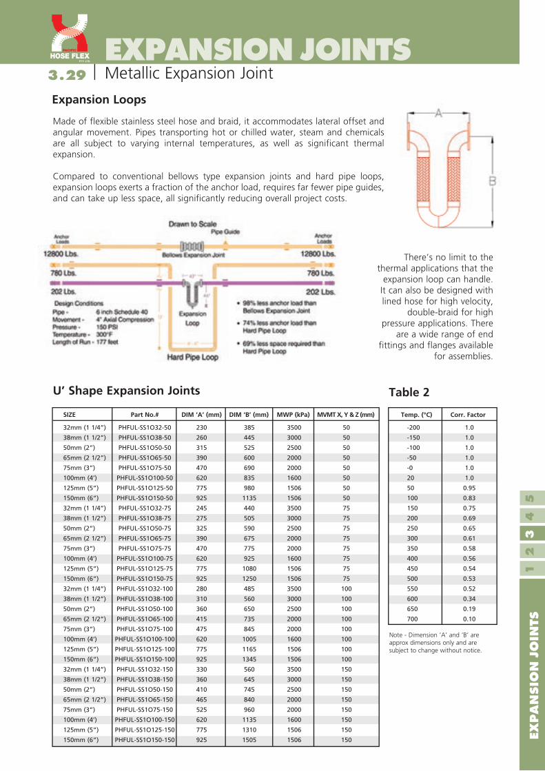
Made of flexible stainless steel hose and braid, it accommodates lateral offset and angular movement. Pipes transporting hot or chilled water, steam and chemicals are all subject to varying internal temperatures, as well as significant thermal expansion.
Compared to conventional bellows type expansion joints and hard pipe loops, expansion loops exerts a fraction of the anchor load, requires far fewer pipe guides, and can take up less space, all significantly reducing overall project costs.
Metallic Expansion Joint
Expansion Loops
U’ Shape Expansion Joints Table 2
Temp. (°C) Corr. Factor
-200 1.0
-150 1.0
-100 1.0
-50 1.0
-0 1.0
20 1.0
50 0.95
100 0.83
150 0.75
200 0.69
250 0.65
300 0.61
350 0.58
400 0.56
450 0.54
500 0.53
550 0.52
600 0.34
650 0.19
700 0.10
32mm (1 1/4”) PHFUL-SS1O32-50 230 385 3500 50
38mm (1 1/2”) PHFUL-SS1O38-50 260 445 3000 50
50mm (2”) PHFUL-SS1O50-50 315 525 2500 50
65mm (2 1/2”) PHFUL-SS1O65-50 390 600 2000 50
75mm (3”) PHFUL-SS1O75-50 470 690 2000 50
100mm (4’) PHFUL-SS1O100-50 620 835 1600 50
125mm (5”) PHFUL-SS1O125-50 775 980 1506 50
150mm (6”) PHFUL-SS1O150-50 925 1135 1506 50
32mm (1 1/4”) PHFUL-SS1O32-75 245 440 3500 75
38mm (1 1/2”) PHFUL-SS1O38-75 275 505 3000 75
50mm (2”) PHFUL-SS1O50-75 325 590 2500 75
65mm (2 1/2”) PHFUL-SS1O65-75 390 675 2000 75
75mm (3”) PHFUL-SS1O75-75 470 775 2000 75
100mm (4’) PHFUL-SS1O100-75 620 925 1600 75
125mm (5”) PHFUL-SS1O125-75 775 1080 1506 75
150mm (6”) PHFUL-SS1O150-75 925 1250 1506 75
32mm (1 1/4”) PHFUL-SS1O32-100 280 485 3500 100
38mm (1 1/2”) PHFUL-SS1O38-100 310 560 3000 100
50mm (2”) PHFUL-SS1O50-100 360 650 2500 100
65mm (2 1/2”) PHFUL-SS1O65-100 415 735 2000 100
75mm (3”) PHFUL-SS1O75-100 475 845 2000 100
100mm (4’) PHFUL-SS1O100-100 620 1005 1600 100
125mm (5”) PHFUL-SS1O125-100 775 1165 1506 100
150mm (6”) PHFUL-SS1O150-100 925 1345 1506 100
32mm (1 1/4”) PHFUL-SS1O32-150 330 560 3500 150
38mm (1 1/2”) PHFUL-SS1O38-150 360 645 3000 150
50mm (2”) PHFUL-SS1O50-150 410 745 2500 150
65mm (2 1/2”) PHFUL-SS1O65-150 465 840 2000 150
75mm (3”) PHFUL-SS1O75-150 525 960 2000 150
100mm (4’) PHFUL-SS1O100-150 620 1135 1600 150
125mm (5”) PHFUL-SS1O125-150 775 1310 1506 150
150mm (6”) PHFUL-SS1O150-150 925 1505 1506 150
SIZE Part No.# DIM ‘A’ (mm) DIM ‘B’ (mm) MWP (kPa) MVMT X, Y & Z (mm)
There’s no limit to the thermal applications that the
expansion loop can handle. It can also be designed with lined hose for high velocity,
double-braid for high pressure applications. There
are a wide range of end fittings and flanges available
for assemblies.
Note - Dimension ‘A’ and ‘B’ are approx dimensions only and are subject to change without notice.

3.30
EXP
AN
SIO
N J
OIN
TS1
23
45
EXPANSION JOINTS
30
Teflon® Expansion Joint
Introduction
Pacific Hoseflex expansion joints are made of contour moulded PTFE (white or black), providing exceptional corrosion resistance and flex-life. The flexible liner is moulded over the metallic sealing face which eliminates troublesome separate gaskets and reduces the chances of bacteria build up. Different numbers of convolutions accommodate varying degrees of misalignment, axial travel and angular deflection between components.They are corrosion proof and non-aging.
These expansion joints have found widespread acceptance in the chemical processing industry and commercial heating and air-conditioning systems as pump connectors and at strategic points throughout systems. Because of their established record of long service life, they are the most economical vibration and sound absorbers available.
They are manufactured with integral steel limit bolts and reinforcing rings enabling the bellow to absorb vibration and allow for thermal movement and misalignment in piping. They also provide resistance to rotational forces which can lead to joint failure, offering long life in coastal, marine, and chlorine rich environments.
They are available in 2, 3 and 5 Convolution models, with varying amounts of allowed movement.
Teflon expansion joints are capable of handling all of the following movements:• Angular misalignment - called angular deflection and angular
rotation, is the displacement of one flange in relation to the other causing them to lie in non-parallel planes.
• Vibration - Absorbing movement caused by generators or pumps that may result in pipe work cracking.
• Longitudinal - also called travel or axial compression and extension.• Parallel misalignment - called offset or lateral deflection, is the
displacement of one flange in relation to the other while they lie in parallel planes.
• Maximum travel is based on installation with no misalignment or angular deflection.
• Maximum Misalignment is based on installation with no Travel or Angular Deflection.
• Combined travel and misalignment are proportionately lower for each type of deflection according to the percentage of the “maximum” that is required for the other.
“Maximum Angular Deflection” may be called angular rotation. It is based on installation with no axial travel or lateral offset.
ANGULAR DEFLECTIONIn addition to noise, vibration transmitted through piping can cause leeks, premature equipment wear and cracked welds. Expansion joints drastically reduce vibration transmission, thereby solving many of these issues.
“Maximum Misalignment” may also be referred to as lateral offset or deflection. It is based on installation with no axial travel or angular deflection.
MISALIGN MENT
“Maximum Axial Travel” may be called longitudinal movement or axial compression and extension. It is based on installation with no misalignment or angular deflection.
AXIAL TRAVEL

3.31
EXP
AN
SIO
N J
OIN
TS1
23
45
EXPANSION JOINTS
31
Teflon® Expansion Joint
2-convolute expansion joints are contour moulded of TEFLON® PTFE by a patented process. They are corrosion resistant, non-ageing, with extraordinary flex life and reliability. The flexible element is formed over the full sealing face of the end flanges eliminating troublesome separate gaskets.
(PEJ2) 2-Convolute TEFLON® PTFE Expansion Joint
Size
(I.D.)
(in.)
A †
Neutral
Length
Max. m
Travel ±
B C Compression
Force
Spring Rate
(lbf / in.)
Extension
Force
Spring Rate
(lbf / in.)
Misalignment
Force
Spring Rate
(lbf / in.)
Weight
(lbs)
Vacuum
Rating
(in. Hg/°F)
1 1 3/8 1/4 2 1 7/8
1/8 104 80 104 2
1 1/2 1 3/8 1/4 2 7/8 2 27/64
1/8 320 180 224 3
2 1 9/16 1/4 3 5/8 3 1/8 512 300 240 7
2 1/2 2 1/4 5/16 4 1/8 3 1/2
1/8 457 278 328 10
3 2 1/4 3/8 5 4 1/2
3/16 648 320 319 10
4 2 5/8 1/2 6 3/16 5 1/2
1/4 480 280 400 18
5 3 1/4 1/2 7 5/16 6 1/2
1/4 440 440 320 24
6 2 3/4 1/2 8 1/2 8 1/4 440 386 440 29
8 4 1/2 10 5/8 10 5/64 1/4 450 390 480 47
10 5 1/4 1/2 12 3/4 11 3/4
1/4 760 600 580 64
12 6 1/2 15 15 1/4 3300 420 700 115
FV/450
FV/400
FV/250
FV/75
Maximum
Misalignment
*
All Dimensions in inches.* At neutral length with limit bolts in place. Maximum (axial) travel is based on installation with no misalignment or angular defection. 12” size supplied only with crest rings in stainless steel.† This is an installation dimension not a limit bolt setting.
NOTE: Angular Deflection approx. 7°. Consult Factory for spring rates for angular deflection.
Flanges available in Carbon steel Zinc Chromate Plated, Ductile Iron and Stainless Steel
Diameters up to 24” are available on request.
NeopreneGrommet
Reinforcing Ring
MoldedBellowsof PTFE
SteelWasher
ElasticStop NutDuctile Iron Flange
Limit Bolt
B C Approx.
A
200
150
100
50
50 100 150 200 250 300 350 400 450˚F
1/2" - 6"
8" - 10"
12" - 24"

3.32
EXP
AN
SIO
N J
OIN
TS1
23
45
EXPANSION JOINTS
32
(PEJ3) Convolute TEFLON® PTFE Expansion Joints
3-Convolute expansion joints are contour moulded of TEFLON® PTFE by a patented process. They are corrosion resistant, nonageing, with extraordinary flex life and reliability. The flexible element is formed over the full sealing face of the end flanges eliminating troublesome separate gaskets.
All Dimensions in inches.* At neutral length with limit bolts in place. Maximum (axial) travel is based on installation with no misalignment or angular defection.† This is an installation dimension not a limit bolt setting.NOTE: Angular Deflection approx. 14°. Consult Factory for spring rates for angular deflection.
Size
(I.D.)
(in.)
A †
Neutral
Length
B C Compression
Force
Spring Rate
(lbf / in.)
Extension
Force
Spring Rate
(lbf / in.)
Misalignment
Force
Spring Rate
(lbf / in.)
Weight
(lbs)
1 1 3/4 1/2 2 1 57/64
1/4 190 82 96 2
1 1/2 2 1/2 2 7/8 2 35/64 1/4 84 66 108 4
2 2 3/4 3/4 3 5/8 3 13/32
3/8 69 76 109 8
2 1/2 3 3/16 3/4 4 1/8 3 13/16
3/8 91 97 160 11
3 3 5/8 1 5 4 41/64 1/2 124 125 194 13
4 3 5/8 1 6 3/16 5 11/16 1/2 220 155 264 19
5 4 1 7 5/16 6 5/8 1/2 320 210 324 25
6 4 1 1/8 8 1/2 8 9/16 289 187 266 30
8 6 1 1/8 10 5/8 10 5/16 9/16 178 218 423 48
FV/400
FV/300
FV/125
Maximum
Misalignment
*Max.
Travel + Or -
Vacuum
Rating
(in. Hg/°F)
Teflon® Expansion Joint
Flanges available in Carbon steel Zinc Chromate Plated, Ductile Iron and Stainless Steel
Diameters up to 24” are available on request.
NeopreneGrommet
Reinforcing Ring
MoldedBellowsof PTFE
SteelWasher
ElasticStop Nut
Ductile Iron Flange
Limit Bolt
B C Approx.
A
200
150
100
50
50 100 150 200 250 300 350 400 450 10 38 66 83 121 149 177 204 232
˚F˚C
1/2" - 6"
8"
10" - 16"
18" - 24"

3.33
EXP
AN
SIO
N J
OIN
TS1
23
45
EXPANSION JOINTS
33All Dimensions in inches.* At neutral length with limit bolts in place. Maximum (axial) travel is based on installation with no misalignment or angular defection.† This is an installation dimension not a limit bolt setting.
NOTE: Angular Deflection approx. 14°. Consult Factory for spring rates for angular deflection.
Size
(I.D.)
(in.)
A †
Neutral
Length
B C Compression
Force
Spring Rate
(lbf / in.)
Extension
Force
Spring Rate
(lbf / in.)
Misalignment
Force
Spring Rate
(lbf / in.)
Weight
(lbs)
1 3 1/2 2 1 57/64 1/2 30 44 22 2
1 1/2 3 1/2 3/4 2 7/8 2 35/64 1/2 75 83 46 5
2 4 1 3 5/8 3 13/32 1/2 60 47 50 9
3 5 1 5 4 41/64 1/2 55 60 170 14
4 5 1/4 1 1/4 6 3/16 5 11/16 5/8 72 60 80 20
6 6 1 1/4 8 1/2 8 5/8 190 130 195 31
Maximum
Misalignment
*Max.
Travel + Or -
Teflon® Expansion Joint
5-convolute expansion joints are contour moulded of TEFLON® PTFE by a patented process. They are corrosion resistant, non-ageing, with extraordinary flex life and reliability. The flexible element is formed over the full sealing face of the end flanges eliminating troublesome separate gaskets.
(PEJ5) Convolute TEFLON® PTFE Expansion Joints
Flanges available in Carbon steel Zinc Chromate Plated, Ductile Iron and Stainless Steel
NeopreneGrommet
Reinforcing Ring
Molded Bellows
SteelWasher
ElasticStop Nut
Ductile Iron Flange
Limit Bolt(factory set)
B C Approx.
A
200
150
100
50
50 100 150 200 250 300 350 400 450 10 38 66 83 121 149 177 204 232
˚F˚C
All Sizes

3.34
EXP
AN
SIO
N J
OIN
TS1
23
45
EXPANSION JOINTS
34
Rubber Expansion Joints
Rubber Expansion Joints (REJ)
Rubber expansion bellows can be used for both suction and delivery (discharge) due to its excellent stability and pressure capacity. Rubber Expansion Joints are generally used as connectors between vessels operating at widely different temperatures ranging up to 115°C. Bursting pressure is above 550 psi and can be comfortably used within a normal internal pressure of approx 225 psi. The sizes range from 32 mm to 500 mm including a wide variety of different flanges and materials. Most common available materials are; EPDM ,Neoprene, Buna/Nitrile, Hypalon, Butyl and natural rubber.
Rubber expansion joints are generally used in heating and air conditioning systems, marine environments, sewage plants, industrial systems and for mild chemicals and oils. Rubber expansion joints permit the necessary motion and flexibility in a ‘working’ ship’s piping system. The compactness, resilience and low stress features make them ideally suited for shipboard piping systems. Sewage treatment plants, water treatment plants and air scrubber systems all employ the use of general rubber expansion joints. Sludge pumps, raw and secondary sewage lines, centrifugal air blowers, scrub stacks use expansion joints due to their resistance to abrasion and corrosion as well as their flexibility make them well suited for these applications.
Rubber expansion joints are designed to alleviate piping stress, absorb pipe misalignment, compression and extension, noise and vibration, in a relatively short space. Standard stock items are the single arch and the twin-sphere joints. The spherical shape arch of the connector and excellent original structural design contribute to the great success of the joint. Combined with it’s internally laid tough flexible fibres and it’s moulding technique, rubber expansion joints have great ability to withstand the force of a creating vacuum. Internal reinforced rings can be inserted to increase the suction capabilities of the bellow.
Nuclear and fossil fuel plants use rubber expansion joints to compensate for thermal expansion and contraction on condense lines, steam turbine exhaust lines, condensate lines, cooling water lines and aeration systems. They have been also successfully installed in demanding industrial ducting systems where flutter, heavy vibration, wet or dry corrosive materials are encountered. Rubber expansion joints reduce noise and vibration caused by forces in pumps or centrifuges by acting as a shock absorber in systems. Thermal movement is also an important consideration in a piping system, depending on the temperature change, length of pipe, thermal movement can easily be great enough to exceed the allowable pipe stress.
MOVEMENT

3.35
EXP
AN
SIO
N J
OIN
TS1
23
45
35
EXPANSION JOINTSRubber Expansion Joints
Single Sphere Rubber Expansion Joint
1. Application fluids: water, warm water, seawater, weak acids, alkalies, etc.
2. Available flanges drilling: JIS, DIN, ANSI, TAB / BS and specialised drilling.
3. Available material: EPDM, Neoprene, Buna/Nitrile, Viton, Hyperlon, Natural
Rubber and Butyle.
Remarks
Maximum Working Pressure(x factor)
Press/Temp
Correction Factor
Operating Temperatures
80°C 85°C 90°C 95°C 100°C 105°C
x1.0 x.92 x.83 x.75 x.67 x.60
Movement and Operating Condition
Diam. Do
mm (in.)
L
(mm)
Allowable Movement (mm) Operating Condition
Angular
Deflection
MaximumPressurekg/cm2 (PSIG)
Max. Temp
°C °(F)
VacuumRating mm
Hg (in.)
32 (1 ¼) 95 8 4 8 15º 16 (225) 115 (240) 400 (16)
40 (1 ½) 95 8 4 8 15º 16 (225) 115 (240) 400 (16)
50 (2) 105 8 5 8 15º 16 (225) 115 (240) 400 (16)
65 (2 ½) 115 12 6 10 15º 16 (225) 115 (240) 400 (16)
80 (3) 130 12 6 10 15º 16 (225) 115 (240) 400 (16)
100 (4) 135 18 10 12 15º 16 (225) 115 (240) 400 (16)
125 (5) 170 18 10 12 15º 16 (225) 115 (240) 400 (16)
150 (6) 180 18 10 12 15º 16 (225) 115 (240) 400 (16)
200 (8) 205 25 14 22 15º 16 (225) 115 (240) 400 (16)
250 (10) 240 25 14 22 15º 16 (225) 115 (240) 400 (16)
300 (12) 260 25 14 22 15º 16 (225) 115 (240) 400 (16)
350 (14) 265 25 16 22 15º 9 (125) 115 (240) 400 (16)
400 (16) 265 25 16 22 15º 9 (125) 115 (240) 400 (16)
450 (18) 265 25 16 22 15º 9 (125) 115 (240) 400 (16)
500 (20) 265 25 16 22 15º 9 (125) 115 (240) 400 (16)
600 (24) 265 25 14 22 15º 9 (125) 115 (240) 400 (16)
STYLE 100
Item Part Material
1 Body Heat Resisting Rubber
2 Body Nylon Tyre Cord
3 Wire Hard Steel Wire
4 Flange Mild Steel
Axial
Compression
Axial
Elongation
Transverse
Deflection

3.36
EXP
AN
SIO
N J
OIN
TS1
23
45
EXPANSION JOINTS
36
1. Application fluids: water, warm water, seawater, weak acids, alkalis, etc.
2. Available flanges drilling: JIS, DIN, ANSI, TAB / BS and specialised drilling.
3. Available material: PDM, Neoprene, Buna/Nitrile, Viton, Hyperlon, Natural
Rubber and Butyle.
Remarks
Twin Sphere Rubber Expansion Joints (TREJ)
Axial
Compression
Nominal
Diameter
Inch mm
Face
to
Face
Inch
Temp
(°C)
Min-Max
Travel
mm Total
Compressed
Extended
Allowable Movement (mm)
Axial
Extension
Lateral
Deflection
Angular
Deflection
Pressure
Positive
P.S.I.G. (Bar)
at 80°C
Vacuum
mm Hg
1-1/4" 32 7 -30 -110 125-205 53 27 45 40° 225(16) 660
1-1/2” 40 7 -30 -110 125-205 53 27 45 40° 225(16) 660
2” 50 7 -30 -110 125-205 53 27 45 40° 225(16) 660
2-1/2” 65 7 -30 -110 125-205 53 27 45 40° 225(16) 660
3” 80 7 -30 -110 125-205 53 27 45 40° 225(16) 660
4” 100 9 -30 -110 175-260 53 31 40 35° 225(16) 660
5” 125 9 -30 -110 175-260 53 31 40 35° 225(16) 660
6” 150 9 -30 -110 175-260 53 31 40 35° 225(16) 660
8” 200 13 -30 -110 265-360 65 30 35 30° 225(16) 660
10” 250 13 -30 -110 265-360 65 30 35 30° 225(16) 660
12” 300 13 -30 -110 265-360 38 30 35 30° 225(16) 660
14” 350 13.78 -30 -110 265-360 38 28 28 20° 150(10) 660
16” 400 13.78 -30 -110 265-360 38 28 28 20° 150(10) 660
18” 450 13.78 -30 -110 265-360 38 28 28 20° 150(10) 660
20” 500 13.78 -30 -110 265-360 38 28 28 20 ° 150(10) 660
Rubber Expansion Joints
Maximum Working Pressure(x factor)
Press/Temp
Correction Factor
Operating Temperatures
80°C 85°C 90°C 95°C 100°C 105°C
x1.0 x.92 x.83 x.75 x.67 x.60

3.37
EXP
AN
SIO
N J
OIN
TS1
23
45
37
EXPANSION JOINTS
Remarks
Fabric Expansion Joints
To complete the entire expansion joint range Pacific Hoseflex provides a fabric expansion joint. Fabric expansion joints are widely used for a large number of industrial applications including:• Power Plants • Boiler Systems • Flue Gas • Nitrogen Oxide Reduction • Gas Turbines • Nuclear Power Plants • Incinerator Plants • Cement Industry
The temperature capabilities range from -50º C to +1000º C and the pressure range from -50 kPa to +50 kPa.
Functions
Fabric expansion joints are used for absorbing movements between joining connections in gas conveying ducts and pipe-lines. The movements can be caused by thermal expansion of the ducting system, wind conditions or vibrations from other system components or machines. In addition, fabric expansion joints can serve as seals and compensate for installation misalignments.
Advantages
The implementation of fabric expansion joints provides a number of advantages, which are technically and economically important:• Extremely flexible absorbing large movements • Absorbing different movements simultaneously • Only requiring a limited building length • Lightweight • Easy to handle, store, install, repair and replace • Does not transmit noise or vibrations.• Reducing the necessary strength of fix-points and supports • Non corroding • Dimensionally stable• Cost effective
• Filter Systems • Ventilators • Ventilation Systems • Dust Extraction Systems • Offshore Installations • Shipbuilding • Chemical Industry
Fabric Expansion Joints (FEJ)

3.38
EXP
AN
SIO
N J
OIN
TS1
23
45
EXPANSION JOINTS
38
Enquiry data sheet
Customer: _______________________________ Contact: ___________________________ Date:________________
Phone:_________________________ Fax: ___________________ Email: ___________________________________
I. Specification Information
Request Quote Yes / No circle one
Place Order P.O.# ____________ Quote ref #________________ Quantity: _________ Date ____________ Required: ___________________ Hose type: ___________ Diameter (mm): ____________ Length (mm):_________
(Live Length / Overall Length) Circle One
End Fittings (type and size for both ends)
End #1: Size: ____________ Type: ____________________ Material: ____________________
End #2: Size: ____________ Type: ____________________ Material: ____________________
Liner Required: Yes / No Circle One If “Yes”, Liner Material: _________________________
Special Fabrication: ____________________________________________________________
Accessories:___________________________________________________________________
II. Application Information
Application Drawing: (sketch the installation and include all dimensions and motions of hose
during application and any other considerations)
Instructions: To place an order or request a quotation, please complete section I. If you need assistance in specifying an assembly, complete Section II as well as the “End Fittings” portion of Section I. When completed, Fax: (617) 55 934 298 or Email: [email protected] this form to Pacific Hoseflex.
Technical Information (Hose Specification Sheet)
Size (mm): __________ (in the event the fittings or hose have different sizes, include all sizes and show on the application drawing).
Temperature: Media: Min. ____ºc Max. _____ºc Environment: Min. ____ºc Max. _____ºc (assumption is 21ºc for all)
Media:__________________ (assumption is the media is compatible with all available materials)
Max. Pressure (psi):_______ Fluctuations (None / Pulsating / Shock) Circle One (assumption is nominal pressure, no fluctuations)
Max. Velocity (feet/second): __________________________ (assumption is velocity is too slow to affect performance)
Type of Motion (from drawing above): (Static / Constant / Vibration) Circle One (assumption is static)
Type of Expansion: ____________________________________________________________
Amount of Expansion of Motion: _______________________________________________

3.39
EXP
AN
SIO
N J
OIN
TS1
23
45
EXPANSION JOINTS
39
Notes

3.40
40
MATERIAL COMPATIBILITYGuide Only
CP
VC
Ep
oxy
Po
lyp
rop
ylen
e
Po
lyet
hyl
ene
PV
C
Cyo
lac
® (
AB
S)
Ph
eno
lic
Nyl
on
No
ryl ®
Del
rin
® (
Ace
tal)
Ryt
on
® t
o 2
00°F
Kyn
ar ®
(P
VD
DF
)
Tef
lon
®
Sta
inle
ss s
teel
(31
6)
Sta
inle
ss s
teel
(30
4)
Sta
inle
ss s
teel
(44
0)
Tit
aniu
m
Car
pen
ter
20
Cas
t b
ron
ze
Cas
t ir
on
Alu
min
um
Has
tello
y C
Car
bro
n.c
eram
ic
Car
amag
net
A
Vit
on
®
Bu
na
N
Neo
pre
ne
®
Nit
rile
Nat
ura
l ru
bb
er
Hyp
alo
n ®
EP
DM
Kel
-F®
Tyg
on
Sili
con
e
Cer
amic
Car
bo
n/g
rap
hit
e
D A A C D D A A A¹ A D A A A - A - A C B A A - D D C D C C A A D A A A- A A¹ A D - D A B¹ A C A A B - - - D D - - - - B A B A D B A A D B A AC A D A D - D A D A A A A A A A A C D A A A - D C D C C C A A D C A AC B¹ A¹ A² D D D D A C A A¹ A A C D A A C D A A A - D C D C B C B A² D B A AA A A A D C C B A B A A A A B D A A C D A A A - B B A B B A A A D B A AC C A A² D D D D A C A C A A C D A A C D A A A - B C³ C C B C A A D B A AC C B A² D D D D A C A C A A C D A A C D A A A - B C³ C C B C A A D C A AD A B¹ D D D A A¹ D D A B¹ A A A D A B C - A¹ A A - D D A D B A B A D C A AD D A B¹ D D A A D C A D A A A B A A A A A A A A D D C D C B A A D B A AC A - D C D - D D D A A² A A A - - B - - A A - - A D D D D D D A D C - -C A A¹ A A¹ - A A - - A A A A A A - A C A A - A A A B B B B B A A - B A AA A A A - D D A - - - A¹ A A¹ A¹ - - A¹ - A¹ B¹ B A A D D C D D C D - - D A BA² D B¹ B² A² - A A¹ C A A A A A A - B A A - B A A - B B A B B A A A B D A AA A¹ A D D D A D D A A A A A¹ A¹ - A A A A B² A A - A D C D D B B A B - A -A² A A A A² - C A A A A - A A A - A A A D B A A - A A A B A A B - B B A -- A B² B¹ B¹ - A A A A - A¹ A A A - A A A A A¹ A A - D D D D D D A - - D A A
A¹ A² A B C B A A A B - - A A A A A A A A B A A A A C A C A A A - C B A -- A - A A² - A A A A - - A A A - A A A A A A A - C A A A A B C - - B A -- A A¹ A² A¹ B C A¹ A A - - A² A A - B A A C B A A - A B A B A A A - - A A A
A² A A² A² A¹ - A B¹ A¹ A - - A² A A - A A A C B B A - A B B B A A A - - A A AA¹ B¹ A² A¹ B¹ - A A A¹ C A A A A A B¹ B A A A A¹ A A A¹ B² A A A A A A A¹ - A A A- A - A C B A A A A - - - A A - A A A A A C A - B B B B B B A - - B A -
A² A¹ A A² A² - C B A² A A A² A A A A A A A C A A A - A A A B² A A A - - A A AA¹ A¹ A B² A¹ B D D A C A A A C¹ D D B C¹ D D D A A - A A A A A B A A B B A AA² A¹ A B² A¹ - - D A - A A A C¹ A¹ A¹ B B¹ D D A¹ A A - A A A A A B A A B B A AA² B¹ A A² A² - - A¹ A¹ C A A A C¹ B¹ D A C¹ - - B¹ B A - A A A A B A A - - B - AA B¹ A A² A² - D A¹ A B - A A D¹ A¹ A¹ B¹ A¹ C A B¹ B A A A A A A² D A² A A¹ - - A AA² A¹ A A² A² - - D A² C - B¹ A B² C B¹ A A - D C C A - A A A A A A A A B A A AA² A¹ A A² A² - - D A² C - - A B² C D A B - D C C A - A A A A A A A A B A A AA² A¹ A A² A² - A A² A C A A A B¹ B D A B C D B¹ B A - A A A A A A A A B A A AD A¹ - C¹ D - D D D D B - A² A A A B B D D B C A - D D B D B D B A - B A AA A¹ A² C¹ B¹ - A A A¹ D A¹ A A A¹ A¹ A¹ C A¹ D A A¹ A A - D A A A D D A A B - A AA A A B² A² - A A¹ B¹ D A¹ A A A¹ A A C A D A A¹ B C - D B C B D D A A A D A AA A¹ A² C¹ A² - A B¹ - D A¹ A A A B² B² C B² D A C A A - D C A C D D A A B - A AB A A - B¹ - A D A C A A A A A A - A D A C - A - D C C C - D A - B - A -A A¹ A A² A² - A - A D - A A - C - - B D D B B - - A A A A² - - A² - - - A AA A¹ A B² A² - D A A² D A A A B B B A B D A B B A - - D A B A - A - B - A A- A - - - - D - A D - - - A - - - - - - - - - - - - A - - - - - - - - -
A² A¹ A² A² A² - A C A B A A A D¹ C C B B D D C A A - A B A B A A A A B - A AA A¹ A A¹ A B A A A C¹ A A A A¹ A¹ B A A A A B² B A - B D A D D A A A B A A AA² A¹ A A A² - D B A C A A A A A¹ A¹ A A D A B¹ B A - A A B A C A A A B - A A- A - - A - D - - B - - - A A A - A D D - A A - - A A - - - - - - - - -A A¹ A A² A² - C C¹ A¹ D - A¹ A¹ B A A A B D D D B A - A D A D A A A A - - A AA A¹ A A² A² - A C¹ A B - A A² B B B A A¹ C C B¹ B A - A A A A A A A A - A A AA A A A A - A B A B - - A C¹ B B A C¹ D D B B A - A A A A A A A - - A A -A A A C A - A B A B - - A B B B A - C A B B A - A A A A A A A - - A A -A A¹ A A¹ A² - A A¹ A - A A A B B B A B D C A¹ B A - A A A A A A A A - A A A- A - A - - A - - B - - - A - - A - D D - - A - - A A A - - - - - - A -
C¹ A¹ B¹ C¹ C¹ - D C² D A A A² A A A¹ B A A C C A A A - D D D D D D A A¹ D D A AA² D B¹ B² A² - A A¹ C A A A A A A - B A A - B A A - B B A B B A A A B D A AC A¹ D D D - - C¹ D A - A A A² A² C¹ C A² A - A¹ A¹ A - B¹ - D B¹ D D D A C D A AC¹ C¹ C¹ B² C¹ D D C¹ D A¹ A A¹ A B A B C A C C C B A - C D D D D D B A² D D A AA A D - A B A D A D - - - A - - - A A A A - A - A A C C A - - - B - A -A² - A B² A² - - D A² - - A A C¹ D D B B - - D - - - A² - - - - - B¹ A - - - -C¹ D B¹ B¹ C¹ - D D D D D A¹ A D¹ D - A D D - D C - - B D C D D C C A D D D D- A¹ D C¹ - - - A¹ - - - - A B B - A¹ - - - A A - - A C D C D D B A¹ - B - -D A D C D - A - D A - - - C¹ - - - - C A A - A - A C D C D D D - - D - -A¹ A¹ A B² A¹ - A C¹ A¹ D A A A A² A² B B A¹ D D D B A - A² A² A A² B A A² - B A A AA² A B¹ A¹ A² - D A - A A - A¹ A B B - A A A A - - A A B C B D D D A - D A AA² A¹ A B² A² - - A¹ A² A - A A B B¹ B¹ A B B - D B A A A A² - A² - - A A - - A A
Derlin,Hypolon,Neoprene,Teflon,Biton- Ryton-Reg TM Phillips Petrolum Co Kynar-Reg TM Penwalt CorpReg TM E.I. du Pont de Nemours & Co Tygon-Reg TM Norton Co Cycolac-Reg TM Mar-Bon CorpKelF-Reg TM Minnesota Mining & Mfg. Co Noryl-Reg TM General Electric Co
A -B -
-CD - Sever effect - Not recommended
Moderate effect - FairMinor effect - GoodNo effect - Excellent
Ratings-chemical effect
gnir-O rof yrotcafsitaS .3 s
Explanation of footnotes1. Satisfactory to 72°F2. Satisfactory to 120°F
ActadehydeAcetamideAcetate SolventAcetic Acid, GlacialAcetic acid 20%Acetic Acid 80%Acetic AcidAcetic AnhydrideAcetoneAcetyl Chloride (dry)AcetyleneAcrylonitrileAlcohol: AmylAlcohol: BenzylAlcohol: ButylAlcohol: DiacetoneAlcohol: EthylAlcohol: HexylAlcohol: IsobutylAlcohol: IsopropylAlcohol: MethylAlcohol: OctylAlcohol: PropylAluminum Choride 20%Aluminum ChorideAluminum FluorideAluminum HydroxideAluminum Potassium Sulfate 10%Aluminum Potassium Sulfate 100%Aluminum SulfateAminesAmmonia 10%Ammonia, anhydrousAmmonia, liquidAmmonia, NitrateAmmonium BilfuorideAmmonium CarbonateAmmonium CaseniteAmmonium ChlorideAmmonium HydroxideAmmonium NitrateAmmonium OxalateAmmonium PersulfateAmmonium Phosphate, DibasicAmmonium Phosphate, MonobasicAmmonium Phosphate, TribasicAmmonium SulfateAmmonium ThiosulfateAmyl AcetateAmyl AloholAmyl ChlorideAnilineAnti-FreezeAntimony TrichlorideAqua Regia (80%HCI,20%HNO3)Arochlor 1248Aromatic hydrocabronsArsenic AcidAsphaltBarium Carbonate

3.41 Guide OnlyMATERIAL COMPATIBILITY
A¹ A¹ A A¹ A¹ - A A² A A A A A A¹ A¹ B A B C C D B A - A A A A² A A A A B A A AD A¹ D B D - - - - B - - A¹ A¹ A¹ - - A¹ C - C¹ - A - A C A C - - A - - - - -A¹ A¹ B B² A² - A A¹ A² D A A A B B¹ B¹ B B¹ A A D B A A A A A A² A A A A - A A AA A¹ A B² A - D A¹ A A - - A¹ B B¹ B A B D A B - A - A A² A A² - - A A - - A AB¹ C¹ B¹ B² B¹ - - A¹ A¹ A A A A B¹ B¹ B B B C - B A A - A A A A A A A A - A B AA² B¹ B B² A² - - A¹ A² A - A A B² B¹ B¹ A A¹ C - D - A - A A A A A A A - - A A AA¹ A¹ A¹ A² A¹ - A A¹ A¹ B - A A A A¹ A¹ B A A D A A¹ A - A A A A A A A A C A A AA² A¹ B¹ A¹ A² B A A A B - - A¹ A A¹ B A A C A A - A - A A A A A A A A - A A AD A¹ A¹ A¹ D B D C¹ D A A A² A¹ B B - A A A A B A A - D D D D D D A A D D A AC¹ C¹ C¹ C¹ C¹ D A A D A¹ A A² A B B B A A A A B B A A A D D D D D D B C D A -A A¹ C¹ B² A - C C¹ A¹ B A A A² B B B B B D D B B¹ A - A D D D D D D A B B B D- A¹ A C¹ - - A D D A A A A A¹ A¹ - - B A A B¹ B A A A D B D D B B A - - A AA A¹ B A² B¹ - D A A¹ A A A A A A A B A A A B¹ B A A A D D D D A A A - B A AA A¹ A A² A² - A B A¹ A A A A A¹ B² B A B² B D D A A A A A A A A A A A B A B A- A - - - - A - - A - - - A - - - A A A - - A - A A A A - - - - - - A -D D D D C¹ D D D A¹ D D A A D D D D D D - D A D D A D D D D D D A B D A DA A¹ D D C¹ - A¹ - A A¹ A A² A A A - A C - A A - B D B D D B C A - D A AC¹ A¹ C¹ C¹ C¹ B A² D A A A A A² A² A A A C A A A - A A A A D B D A C D A AA D A¹ A² B¹ - A B¹ A A A A A² A¹ A A B A A - B A A - A A A A A A B A¹ B B A A- A - - - B D - B A - - A A C - - - D D A A - A A B A D B A - B B A -
A¹ A¹ A¹ A¹ A¹ B D B¹ A A - - A A A A - - D D A A A - A A A A D - - A B - A AA¹ A¹ - B¹ C¹ - A B¹ - A A A A A A A - A D - A - A - A B C B D D D B¹ D A AC¹ B¹ B¹ C¹ D - D A D A A B² A A B B A B¹ A A B A A - D D D D D D B A¹ D D A AA C¹ C¹ D B¹ D D B¹ A¹ C A B A² B² B² C² A B A D B A¹ A - B¹ D D D - D B A C - - -- A¹ - - - - D - - - - - - A - - - - C D - - - - - - A - - - - - - - A A
A¹ A A - A² - - A A D - - A B B - A B C - C - A - A A¹ A A¹ - - C A - - A AB¹ A B A¹ B¹ - - A² A¹ D A A A A B D A B¹ - - D B - - A A¹ A A D A D A - A A AA A¹ A B² A² - - A A² A - A A B A¹ A B B¹ A - D B A - A A¹ A A A A A - - A A AA - - - A² - A - - - - - A - - - - - - - - - - - A C - C - - A - - - - -A² A¹ A² B² A² B A A¹ A D A A A B² C² C¹ A B A C D A A B A A A A A A A A - A A AA² A¹ A² B² A² - D A² A² D A A B C C A B D A C¹ A A A A A A A A A A A - A A AB¹ A¹ A² B² B¹ - A C¹ A D A A A B C¹ D A¹ B D D D B A - A C¹ C C¹ D A B¹ B¹ A B A AA² A¹ A² B² A² C D D A D A A A B B B A B A A C B A - A A² C A² - - A A - - A A- A A - - - D A A B - - - A A - - - C D - - A - A A A A - - A - - - A -
A² A C¹ - A² - A A - A - - A A A - - A A A B - A - A A A A A A A - A A A -A C¹ B² B¹ C - D D D D A A² A B B B A B A D B A A A A D C D D C B A¹ C D D AA A C¹ - D - - A - A - - - B A A - B B - B - A A A C D C - D D - D - A -A A¹ A² C¹ A B A A¹ A¹ A A A A A¹ A A A A A D B A A - B A B A B B B A - B A AA A¹ A² C¹ A B A A² A¹ A A A A A¹ A A A A A D B A A - B A B A B B B A - B A AA A¹ A² C¹ A B A A² A¹ A A A A A¹ A A A A A D B A A - B A B A B B B A - B A AC¹ C¹ D C¹ D - A B¹ A¹ A¹ A B² A B A¹ B B B D A A B A - A¹ D D D D D D A - - B AA² A¹ A B² A² - A A A² A - B A A A A - A C D A A A - A A A A B A A - - A A AC¹ A¹ B¹ B¹ B¹ D A D D B¹ A A A B B B A B A C D A¹ A A A C D C D D D A¹ C D A AA A B A A - - A A A - - - A A A - A C D A - A - A A A A - - - - - - A -A B¹ B B² A² - A A¹ A¹ B¹ A A¹ A A A¹ B B¹ A A D B¹ A¹ A - A B A B A A A A - A A AA A¹ A - A B D A A B - - - A A A - A D D D - A - A A C A - - C - - - A -B¹ C¹ C¹ C¹ B¹ - - D - D A A¹ A A¹ B¹ D A¹ C² - - D B A - D B D B D B A² D - - AA - - - A² - - D D D - - A C D D - A - - D A - - - - - - - - - A - - - D- A - - - - D - - - - - - A - - - - A D - - - - A C D C - - B - - - - -
B² C¹ B B² C¹ - D D B¹ A¹ D B A C C¹ D B C D C D B A - A D D D D C C B² C - D AA² - C¹ B A² - - D B¹ D D A A B C¹ C D A - - C¹ B - - A D C D D B A D - D - AA² A¹ C¹ B¹ A² - - C¹ C¹ D D B A C C D A B - - D A - - A D D D D C C A - - - AD C¹ C¹ C¹ D D D B D A¹ A A B B A B B B A D A B A - A D D D D D D A¹ A D A AD C¹ C¹ C¹ D D A D D B¹ A A A¹ A B¹ A A² A D D B¹ A¹ A A A D D D D D D B¹ A D A AC¹ C¹ D D C - D D D D D C¹ A B² D D A C D D C² A¹ - - C D D D D D D A² C D C A- A A - - - D A A A - - A A A - - - D D A - - - A A A A D - - - - - A -A B¹ A B A B C D A¹ B¹ A A A A B B¹ A B¹ D D C B D - A D D D B B A A B C C AA² C¹ A A² A² B D D A¹ B¹ A A A B B B¹ B B¹ D D D B D - B D D D D B C A C C C AB² C¹ A² A² B² C C D D C B A² A B² B¹ C A B² D D D B D - A D D D D B B A B C D AC² D B¹ A² C² C C D D D A¹ A² A B² C² D A² C¹ D D D B¹ D - A D D D D B B A² B C D A¹
CP
VC
Ep
oxy
Po
lyp
rop
ylen
e
Po
lyet
hyl
ene
PV
C
Cyo
lac
® (
AB
S)
Ph
eno
lic
Nyl
on
No
ryl ®
Del
rin
® (
Ace
tal)
Ryt
on
® t
o 2
00°F
Kyn
ar ®
(P
VD
DF
)
Tef
lon
®
Sta
inle
ss s
teel
(31
6)
Sta
inle
ss s
teel
(30
4)
Sta
inle
ss s
teel
(44
0)
Tit
aniu
m
Car
pen
ter
20
Cas
t b
ron
ze
Cas
t ir
on
Alu
min
um
Has
tello
y C
Car
bro
n.c
eram
ic
Car
amag
net
A
Vit
on
®
Bu
na
N
Neo
pre
ne
®
Nit
rile
Nat
ura
l ru
bb
er
Hyp
alo
n ®
EP
DM
Kel
-F®
Tyg
on
Sili
con
e
Cer
amic
Car
bo
n/g
rap
hit
e
Derlin,Hypolon,Neoprene,Teflon,Biton- Ryton-Reg TM Phillips Petrolum Co Kynar-Reg TM Penwalt CorpReg TM E.I. du Pont de Nemours & Co Tygon-Reg TM Norton Co Cycolac-Reg TM Mar-Bon CorpKelF-Reg TM Minnesota Mining & Mfg. Co Noryl-Reg TM General Electric Co
A -B -
-CD - Sever effect - Not recommended
Moderate effect - FairMinor effect - GoodNo effect - Excellent
Ratings-chemical effect
gnir-O rof yrotcafsitaS .3 s
Explanation of footnotes1. Satisfactory to 72°F2. Satisfactory to 120°F
Barium ChlorideBarium CyanideBarium HydroxideBarium NitrateBarium SulfateBarium SufideBeerBeer Sugar LiquidsBenzaldehydeBenzeneBenzoic AcidBenzolBorax (Sodium Borate)Boric AcidBrewery SlopBromineButadieneButaneButanol (Butyl Alcohol)ButterButtermilkButyleneButylacetateButyric AcidCalcium BisufateCalcium BislfideCalcium BisulfiteCalcium CarbonateCalcium ChlorateCalcium ChlorideCalcium HydroxideCalcium HypochloriteCalcium SulfateCalgonCane JuiceCarbolic Acid (See Phenol)Carbon BisufideCarbon DioxideCarbon Dioxide (Dry)Carbon Dioxide (Wet)Carbon DisufideCarbon MonoxideCarbon TetrahlorideCarbonated WaterCarbonic AcidCatsupChloroacetic AcidChloric AcidChlorinated GlueChlorine, anthydrous liquidChlorine, dryChlorine WaterChlorobenzene (Mono)ChloroformChlorosulfonic AcidChocolate SyrupChromic Acid 5%Chromic Acid 10%Chromic Acid 30%Chromic Acid 50%

3.42MATERIAL COMPATIBILITYGuide Only
- A A B A - D - A B - - - A A A - A A D B - A - A A A A - - - - - - A -B² A¹ A A¹ B² C A A¹ A¹ B¹ A A A A² B² C² A² A² C D C A A B A A A A A A A A² A A A- A A - - - D - A B - - - A A - - A D D C - A - A A D A - - - - - - A -A A D - A B D A A D C - A A A - - - D D A A A - A B B B D B B D B - A -A A A - - - - A A A - - - A A A A A D - A A A - A A A A A A A - - A A -A A A B A - D A A B A - A D D B A B D D D - - - A A A A A A A - B A A -A B¹ A B² A² - A A¹ A¹ B A A A B B B B B C D D B A - A A A A A A A - - A A A- A - - A - A - - B - - - D D - - - D D - B A - A B A B - - - - - - - -A A¹ A B² B² - - D A¹ D A A A B A B B B D - D A¹ A - A A A A - - - A - - A AA A¹ A B² A² - A C² A¹ D A A A B B B A B C D D A A - A A A A B A A A - A A AA A¹ A B² A² - A C² A¹ D A A A B B B A B C D D A A - A A A A B A A A - A A AA A A - - - A A A A - - A A A - - A D D A - A - A A C A - - - - - - AD A¹ D C¹ D D D D D D A A² A A² - B A C C A B² A - A D D D D D D A¹ D D A AA A¹ D B¹ C¹ - D D - D - B¹ A A A¹ A¹ A¹ A¹ C C B B¹ A - A D D D D D D - - D A A- A¹ - - - - D - - D - - A A A - - - D D - - - - A C C C - - - - - - - A
B¹ A¹ C¹ B¹ D - D A D A¹ A A A A A - A A D A A B A - A A D A D D D A D D A AA A¹ B¹ A¹ A B - A¹ A¹ A¹ A - A A¹ A¹ - A² A - B B A - A A B A B B A A A A AD B² A¹ C¹ D - - C¹ A¹ A¹ - A¹ A¹ B B - B¹ A - - - A - - C - D - D - - A² D - - AA² A¹ A¹ C¹ A² - - A D A A A A A A - B - A A A B A - A A B A D B D A¹ - D A AD A B² D D - - A - B - A¹ A B¹ - A D - A - B¹ - A A D C C C B C B A A B A A- C¹ B² B² A B - A¹ A¹ A - - A² A² A A A - A A B¹ B A A A A A A A A A - A B A A- A D - D - - - - D A B² A¹ B¹ B¹ A A¹ A A B¹ B¹ A A A A D A D D D - D C A -- A - - B² - - A A C - - - A A A - - C - B - - - A - C - - - - - C - - -
A² A A A² A² - A A¹ A¹ B A A A B B¹ B A¹ A C A B¹ B A A A A A A B A A A B A A A- A¹ C¹ - D - - D - - - A A A¹ - A - - A - - - A A A A B A D B D - A D A A- A¹ B - D - A A A D A C A A A A B A A - B¹ B A A D B B B B C C D - B A AD A¹ D C¹ D - D A D A¹ A B¹ A B¹ B¹ B¹ A¹ A A C B¹ B¹ A A C D D D D D C B¹ D D A AD C¹ B C¹ C¹ C A A² D A A A¹ A B B B¹ A¹ A A A B² A A A D D D D C D B A¹ B A A AD A¹ C¹ C¹ D D D A¹ D A¹ A A A A A A C A A C B B A A A A B A B D A B¹ - D A A- A¹ - - - - - - - - - - A D - A - D A - - - A A A A - A - - - A B C A AD B¹ C¹ C¹ D - - B¹ D A¹ A A A A A¹ D B¹ A - - B¹ - A - B D D D D D D A¹ B B A AD C¹ C¹ C¹ D D D B¹ D B¹ A A A A¹ A¹ A B A¹ C A B² B C - A D D D D D C A¹ D D A AA C¹ A² A¹ A¹ B A B¹ A¹ B A A A A¹ A¹ B A¹ A A A B¹ B¹ A A A A A A A A A A B A A AC¹ A¹ C² C¹ C¹ - D A¹ A¹ - D A A C¹ C¹ - - A¹ A D D - A - D D D D D D C A - D A AB¹ A¹ B² A B¹ - D A¹ A¹ A¹ - A A A B B B A C C A A A - A B B B C D D A B C A AA A¹ B¹ A¹ A² - A A A D A A A C¹ D D A D D D D B² A - A A B A A B A A¹ B B A AA A¹ B B² A² - - A¹ A¹ D A A A A¹ B¹ B¹ A A D - C¹ B¹ A - A A A A A A A A - C A AA A¹ B A² A² C D A¹ A¹ D A A A A¹ B B A¹ A D D C¹ A¹ C - A A A A A A A A B B A AA A¹ A A¹ A² - A C¹ A¹ D A A A C¹ D D A C¹ C D D B¹ A - A A A A A A - B¹ B - A AA A¹ A A¹ A² - - C¹ A¹ D A A A B B¹ B A¹ B D D A¹ B A - - A² - A² - - A A B - A AA² A A B² A² - A D B - A A¹ A C B¹ - D B¹ D D D A¹ A - - A A A A A A² - B - D AA¹ D D C¹ D - - D - - D A¹ A C C C D C D D D B¹ D - B - - - - - A¹ A - D - CA² C A B¹ A¹ - - D B² - A A¹ A B¹ C C D B² D D C B A - - A A A A A A² C B - D AA¹ A¹ A¹ A² A¹ - - C¹ A A¹ A A² A A¹ A¹ B B A A B B B - A A B B B - - A A - - A AA A C B A B B D - A B A A A C B A - A C A A A A D C C C B C A A B B A -A¹ C¹ A¹ B² A¹ B C C A D A A² A C B B¹ C¹ A¹ C D B¹ A A B C B A B A A A A¹ B B A AA² A D C A² C - D - D A C C A C A B - A C - A A A A B D B D A D - D D A -A² A D C A² C - D - B A A A - D A B - A A A A A A B A A A B A B C D D A -B A A - B - - B - A A D A - - A A - A C - A A A D D A D A A A - D D A -B A D - B - - - - A A B A - - A C - A - - A A A B A C A D A D - D D A -B A D - B - - D - A D B D - - A B - A - D A A A B A A A D A D - D D A -A A A - A B D A A A - A A A - A A - C D A A A A A A A A D - - A B - A -- A¹ C C¹ A² D - A¹ A¹ B A B A A A A A A A A C¹ A¹ A A A B C B D D D A B C A A- A¹ D D A - A - - D A D A A A¹ A - - A - A - - A - D D D D D C A¹ A D - -D A¹ D C¹ D D D B D D A B² A B B B A¹ B A A A¹ B A - D D D D D D B B¹ A D A AC - A B² A² - - B¹ - - A A¹ A B B B A B A - C¹ B¹ - - A B B B A B B - A - - BC¹ A C¹ C¹ C¹ D A A D B A A A A A A B A A A A² A A A A A B A D B D A A D A AA² B A A² A² - D A¹ A² A - A A A² A² A² A A A D B² A A A A A A A A A A - A A A AA² B A A² A² B A B¹ A² A B A A A A¹ A A - A A A A A A A A A A A A A - A A A AA A - A¹ C - - A¹ - A - - A A² A¹ A A A A A C A A A A A A A A A A - C A A B
CP
VC
Ep
oxy
Po
lyp
rop
ylen
e
Po
lyet
hyl
ene
PV
C
Cyo
lac
® (
AB
S)
Ph
eno
lic
Nyl
on
No
ryl ®
Del
rin
® (
Ace
tal)
Ryt
on
® t
o 2
00°F
Kyn
ar ®
(P
VD
DF
)
Tef
lon
®
Sta
inle
ss s
teel
(31
6)
Sta
inle
ss s
teel
(30
4)
Sta
inle
ss s
teel
(44
0)
Tit
aniu
m
Car
pen
ter
20
Cas
t b
ron
ze
Cas
t ir
on
Alu
min
um
Has
tello
y C
Car
bro
n.c
eram
ic
Car
amag
net
A
Vit
on
®
Bu
na
N
Neo
pre
ne
®
Nit
rile
Nat
ura
l ru
bb
er
Hyp
alo
n ®
EP
DM
Kel
-F®
Tyg
on
Sili
con
e
Cer
amic
Car
bo
n/g
rap
hit
e
CiderCitric AcidCitric OilsClorox (Bleach)CoffeeCopper ChlorideCopper CyanideCopper FluoborateCopper NitrateCopper Sulfate 5%Copper Sulfate >5%CreamCresolsCresylic AcidCyanic AcidCyclohexaneDetergentsDichloroethaneDiesel FuelDiethylamineDiethylene GlycolDiphenyl OxideDyesEpsom Salts (Magnesium Sulfate)EthaneEthanolamineEtherEthyl AcetateEthyl ChlorideEthyl SulfateEthylene ChlorideEthylene DichlorideEthylene GlycolEthylene OxideFatty AcidsFerric ChlorideFerric NitrateFerric SulfateFerrous ChlorideFerrous SulfateFluoboric AcidFluorineFluosilicic AcidFormaldehyde 40%Formaldehyde 100%Formic AcidFreon 11Freon 12Freon 22Freon 113Freon TFFruit JuiceFuel OilsFuran ResinFurfuralGallic AcidGasolineGelatinGlucoseGlue: P.V.A.
Derlin,Hypolon,Neoprene,Teflon,Biton- Ryton-Reg TM Phillips Petrolum Co Kynar-Reg TM Penwalt CorpReg TM E.I. du Pont de Nemours & Co Tygon-Reg TM Norton Co Cycolac-Reg TM Mar-Bon CorpKelF-Reg TM Minnesota Mining & Mfg. Co Noryl-Reg TM General Electric Co
A -B -
-CD - Sever effect - Not recommended
Moderate effect - FairMinor effect - GoodNo effect - Excellent
Ratings-chemical effect
gnir-O rof yrotcafsitaS .3 s
Explanation of footnotes1. Satisfactory to 72°F2. Satisfactory to 120°F

3.43 Guide OnlyMATERIAL COMPATIBILITY
A A A A¹ A¹ C A A¹ A A A A A A A² A A A A A A A A A A A A A A A A A A A A AA A A A² A² B - - - A A A¹ A A A A B¹ - - - - - A - A A A A A A A A¹ - A A A- A - - - - A - - A - A D A A A - - A D - - - A A A A A - - - - A - A -A A - B B B A A - A - A D A A A A A C D - - - A A A A A - - - - B - A -- A - - A - D - - D - A A A - A - A A A - A - A A D D D - - - - B - A -A A C² B¹ C¹ D D A A¹ A A A A A A A A A A A A A A A A A A A D A D A - D A BB¹ B B¹ C¹ B¹ - D A¹ - A A A A A A A A A A A A A A A A A B A D B D A - D A A- A A B A - D A - A - A A A - A - A A A A A A A A - - - - - - - A - A -- A D C A - D A¹ - B D A A A A A - A A A A A A A A A B A D B D - A C A B- A D A A - - A¹ - - - A A A A A - A A - A A A A A - - - - - - - A - A BD A C - - - A - - B - A C A A - - - D C - - - - A B B B - B A - - C A -A B¹ A² B² B² - D D B C - A - D D D A - D D D A¹ A A A D B D A A A A B D - AA² D C¹ B¹ A¹ B D D B D A¹ A A D D D A - D D D C A B A D D D A A A A B D A AA A B A² A² - - A¹ A - A A A D D D C A D A D A A - - - - - - - - A - - A AA² A¹ B² A² A² A A D A C A A A D D D C D D D D A¹ A A A - - - - - - A B - A AA² A C B² B A C D A C A A A D D D C D D D D - A C A B B B B¹ A A A C B A AA - B¹ - B² A - D A C A¹ A A D D D D D D D D B² A C A D D D D D C A - D A AA A A A² A¹ B D C¹ A¹ B B A A B¹ B¹ B¹ B A D D B¹ A¹ A A A B A B - - A - B - A AA - A - A - - - C C - - A - - A A - D - - - - - A B A B - - A - - - A -C¹ A A² A² B C D C¹ C¹ D A A A D D D D B² D D D A B C A¹ B¹ B¹ B¹ B¹ A¹ A¹ A¹ D D C AC¹ C² A² A¹ B¹ C D D D D A A A D D D D B² D D D B² D D A¹ B¹ B¹ B¹ B¹ A¹ A¹ A¹ D D D AC¹ B¹ C¹ C¹ C C D D D D B A A D D D D B¹ D D D B² D D A¹ D D D D A C A¹ D D D A²C¹ - C¹ - C D D D D D D A A B¹ B¹ D D B¹ D D D B D D A¹ D D D D A C - D D D -A C¹ A B¹ A² - D D B² B A A A B¹ C² D D B² D D D B A D A A C A - - A A A - A A- C¹ A B¹ B¹ - - D B² A A¹ A¹ A C² D D D B² D D D B A - A B B B A A A A D D A A
A² - A A² A² - - A² A¹ - A A A A A A A A A - A A - - A A A A B A A A A C - AA C¹ B¹ A² A¹ A D C¹ A² D A A A B B² B B¹ B¹ C C A A A A A - - - - - - A D B A CA B B¹ C² A¹ - D D A² D A¹ A A B B² B B¹ B¹ B B A A - - A - - - - - - A - B - CA - B¹ C² A¹ - D D - D - A¹ A A² B² B¹ B¹ B¹ B - A A - - A - - - - - - A - B - CA A B¹ C² C² B D D A D C A¹ A A² B² B¹ B¹ B¹ D B A D - A A B A B B B A A D B - CA A A¹ A B¹ B D C¹ A¹ C A A A C¹ C C A A D D B A¹ A A D D A D D B A A¹ D C A AA A A¹ A A² - D C¹ - - A A A B C¹ C¹ A B D D B A¹ - A D A A A A A A A¹ D C - AA A - - D - - - - A - A - - - - A - D B - - A A A A A A - - A - - - A -- A - - C B - C - A - A D C C - - - D D - - A A A A A A D - - - C - A -D C C A¹ D D - D C¹ D D A² A C C C C A D D A B D A A B D B - B B A D - D A- - - B - - - C - D - A - - - - D B - - B D - A - - - - - - - - - - - -- - - - A - - - - - - C C B - - - - A - - A - - - - A - B - A - C - - -- A D - A - - D - - - A - - - A - - - - D - - A A A D A - - - - - - - -- A B¹ B¹ D - - B¹ - D - D A A C A - A¹ B - B B - A D D D C D D B - - D A A- D B A B - - A¹ - D - D A¹ A A - - A A - A A A A D B C B D C D A A D A A- A A¹ B A¹ - D A¹ D A¹ A A A A A A A A A A A A A A A A D A D D D A A D A A- A A¹ C¹ A² D A A D A² A A A A A A A A A A A A A A A A C A D D D A D D A A- C C C¹ B D - A² D D A C¹ A A A C A A A - A A C A D D D D A - D B¹ D - C A- A C B¹ C - A A¹ D D - D A A A¹ A - A A C A A A A D D D D D D D - A D A A- A C B¹ C - A A¹ D D - - A A A¹ A C A A C A A - A D D D D D D D - - D - A
A¹ B¹ A¹ A¹ B¹ B D C¹ A B A B¹ A B¹ B¹ B¹ B B² C D B B¹ A A A A A A A A A A¹ B A A A- B B¹ B¹ A¹ - D A¹ A B - A A A A A A A A A A A A A A A C A D D D - A B A A- A A² - - B D A¹ - C - A A A² A² - - - A - A A - A A A - A - - A - A - - -
A² A A¹ A² A² B - B¹ A¹ D A A A B¹ B B¹ A¹ B¹ A A D B¹ A A D B B B A D A A B D A A- A A² A¹ A² - - B¹ - A - A A¹ C C A - - - - C - - - A B A B B A A - - B - -- A A² C² - - - D - B - A - A - A - - A - D - - A A A B A D C D - A D - -- A - B¹ A¹ - D A¹ - B - A A¹ A A A A - A A D - A A A A A A - - D - A - A A- A A¹ D B² - A A¹ C¹ A A A A A² A² A² A A² A A A² A A A A A B A D D D - B D A A
A² A A A² A² B - - A² A - A A¹ A¹ A¹ A¹ A A A - B - - A A A² - A² - - A - - - - -A A A A² A² B A A¹ A A A A A A¹ B¹ B A B C D D A² - A A A A A A A A A B A - AA A A A² A² B D B¹ A² A A A A A¹ B B A B A A C¹ B¹ A A A B B B B A A A C A A AA A A A² A² B A A¹ A¹ A A A A A¹ A A A A D D C A - A A A A A - - A - - - - -- A - - - - D - - A - - - A - A - - A A - - - A C A A A - - - - - - - -A A A A² A² B A A¹ A¹ A A A A B B B A A C A B¹ A² A A A A A A B A A A B A A AA A A B² A² - - B¹ A¹ A B A A B A A A B A A B¹ B A A A D D D D D D - C - A A
CP
VC
Ep
oxy
Po
lyp
rop
ylen
e
Po
lyet
hyl
ene
PV
C
Cyo
lac
® (
AB
S)
Ph
eno
lic
Nyl
on
No
ryl ®
Del
rin
® (
Ace
tal)
Ryt
on
® t
o 2
00°F
Kyn
ar ®
(P
VD
DF
)
Tef
lon
®
Sta
inle
ss s
teel
(31
6)
Sta
inle
ss s
teel
(30
4)
Sta
inle
ss s
teel
(44
0)
Tit
aniu
m
Car
pen
ter
20
Cas
t b
ron
ze
Cas
t ir
on
Alu
min
um
Has
tello
y C
Car
bro
n.c
eram
ic
Car
amag
net
A
Vit
on
®
Bu
na
N
Neo
pre
ne
®
Nit
rile
Nat
ura
l ru
bb
er
Hyp
alo
n ®
EP
DM
Kel
-F®
Tyg
on
Sili
con
e
Cer
amic
Car
bo
n/g
rap
hit
e
Derlin,Hypolon,Neoprene,Teflon,Biton- Ryton-Reg TM Phillips Petrolum Co Kynar-Reg TM Penwalt CorpReg TM E.I. du Pont de Nemours & Co Tygon-Reg TM Norton Co Cycolac-Reg TM Mar-Bon CorpKelF-Reg TM Minnesota Mining & Mfg. Co Noryl-Reg TM General Electric Co
A -B -
-CD - Sever effect - Not recommended
Moderate effect - FairMinor effect - GoodNo effect - Excellent
Ratings-chemical effect
gnir-O rof yrotcafsitaS .3 s
Explanation of footnotes1. Satisfactory to 72°F2. Satisfactory to 120°F
GlycerinGlycolic AcidGold MonocyanideGrape JuiceGreaseHeptaneHexaneHoneyHydraulic Oil - PetroleumHydraulic Oil - SyntheticHydrazineHydrobromic Acid 20%Hydrobromic Acid 100%Hydrochloric Acid - Dry GasHydrochloric Acid 20%Hydrochloric Acid 37%Hydrochloric Acid 100%Hydrocyanic AcidHydrocyanic Acid (Gas 10%)Hydrofluoric Acid 20%Hydrofluoric Acid 50%Hydrofluoric Acid 75%Hydrofluoric Acid 100%Hydrofluosilicic Acid 20%Hydrofluosilicic Acid 100%Hydrogen GasHydrogen Peroxide 10%Hydrogen Peroxide 30%Hydrogen Peroxide 50%Hydrogen Peroxide 100%Hydrogen Sulfide (aqua)Hydrogen Sulfide (dry)Hydroxyacetic Acid 70%InkIodineIodine (in alcohol)IodoformIsobutaneIsopropyl AcetateIsopropyl EtherJet Fuel (JP3: JP4: JP5)KeroseneKetonesLacquersLacquer ThinnersLactic AcidLardLatexLead AcetateLead SulfamateLigroinLimeLubricantsMagnesium CarbonateMagnesium ChlorideMagnesium HydroxideMagnesium NitrateMagnesium OxideMagnesium SulfateMaleic Acid

3.44MATERIAL COMPATIBILITYGuide Only
- A D - - - - - - D - A - - - A - - - - A - A A A D D D D D D - - - A -- - A¹ B² A² - - C¹ - A - A A A² A B¹ A B² A - B¹ B - A A A B A A B D - D B - A- A - - - - - A - A - - - A - A - - A - A - A A A A A A - - A - A - A -- A - B D - - A - - - A D A C A - - D D A A A A A C A C D - - - D - A -
A² A A - A² - D A - - - - A D - - - - D D - - A A A C D C - - A - D - A DA A A A² A² - A D A² B A A A C D D A¹ D D D D C A A A A A A A A A A D - A CA A A A² B² - - A A² - - A A B B D A A D - D - A A A A A A D - - A D - A AA A B A² B B D A² A¹ A - A A A A A A A D A - A² A A A A A A A A A A D - A CA B¹ A A¹ A¹ B A C¹ A¹ A A A A A A B² B A A A A¹ A A A A A A A A A A A² A A A A- D D B¹ D - - A² - B - D A A A - - A A - A A A A D D B D D D B A A D A A- A D - - - - - - B - D - - - - - - - - - - A A D D B D D D B - - D A -- C - - - - - A - D - D A A A - - A B - A - - A A D D D A - - - A - - A
A¹ B¹ A² A¹ A¹ - A C¹ A¹ A A A A A A B¹ B A A A A¹ A - - D A A A A A A A² A - - AD B¹ C - D D - C - D - A A A A B - - - - - - A A A B D B D D D - - A A A- C D - A - - D - D - D - A - B - - A - - - A A D D D D D D A - D A A -- C B¹ - B² - - C - D - A A A A C - A - - A - A A D C B C D D B - D A A A- A D1 C¹ D - - C D D A¹ A A A A C A B² C A D B A A A D D D D D C A¹ D A A A- A D - A - - C - D - A - - - A - - - - - - A A A D - D - - D - - - A -D C¹ A¹ B² D D A A¹ D B A C² A A A B A A A A A² A A A D D D D D D A A¹ D D A A- C C¹ B¹ D - A A¹ D D A A¹ A A² A B A A C¹ A A² A A A D D D D D D C A - D A A- C D - - - A - - D - D - A - B - A A - - A A A D D D D D D B - - D A -- A D - - - - - - D - D - - - A - - - - - - A A D D D D D D D - - C A -- A - - A - - - - - - - A A - A - - D - - - A A D C¹ - C¹ B - A¹ - D - A -D A B¹ C¹ D D A C¹ D A¹ A¹ B² A B B B B B A A A¹ B A A B D - D B - D A D - A AA A B A² A² B A A² A² A - A A A² A² B A A C D A A A A A A A A A A A A B A A AA A A A A² B A A¹ A² A - B² A A A B A A D A A A A A A A A A A - - A B - A AA A A A B - D A¹ A C - A A A A C A A D D B A A A D C A C B - - - B - A AA A C A C D A A¹ D D A A A A A A B A B A A B A A A C D C D D D A C D A AD A B² A D D A A¹ D D A A A A A A A A C A B¹ A A A A D D D D D D A C D A AA A A B² A² B A C¹ A¹ A A A A C D D A B¹ D D D B A A A A B A A A A A B A A AA A A B² A² B C A¹ A¹ A A A A B¹ B B B B C D D B A A A A A A B A A A A A A A- - C - D - - - - - C - A C C - A - D A D A D A - - A - C - - - D - A -- D C - D - - - - - D - A C C D C - D C D A D A - - A - C - - - D - A -- - C - D - - - - - C - A A C - - - D - D A D A - - A - C - - - D - A -- - C - D - - - - - C - A D C - C - D C D A D A - - A - C - - - D - A -A A¹ A² B² A¹ B D C¹ A D A¹ A A A A B A¹ A¹ D D D A¹ D B A D B D D B B A¹ D C C AA² B¹ A² C¹ A¹ B D D B² D A¹ A A A A B A¹ A¹ D D D A¹ D C A D D D D D B A¹ D D D AA¹ D D C¹ B¹ C D D B² D B A A A¹ A B A¹ A¹ D D C A¹ D A A D D D D D D A D D D DD D D C¹ D D D D B¹ D B¹ A A A¹ A C A¹ A² D D A² B¹ D A A D D D D D D A¹ D D D DA - A - A - - - - D - - A A A - - - A - - - - A A - D - C - A - A - A -D C¹ B¹ C¹ D D D B¹ D B A A¹ A A B B A A C C A¹ D A - B D D D D D D A¹ D D A B- A A - D D D A D D - A A A A A D A A A D B A A C D D D D D B - D D A -- A - - - - A - - D - - - A - A - A A A - - A A - - D - - - - - - - A -- A - - - - A - - D - A - A - A - A A A - - A A A - D - - - - - - - A -- A A - - - - - - D - A - A - A - A A A - - A A A A D A - - - - A - A -A A A - A - A A - A - A A A A A A - A A - - A A A A A A A A B - A A A -- A - - - - A - - D - - - A A A - - A - - - A A A - C - - - - - - - A -- A - - - - A - - D - A D A - A - - D D A A A A A - D - - - - - D - A -- A - - - - A - - - - - - A A A - - A - B A A A A A C A - - - - - - A -
A¹ A A¹ - A¹ - A - - A - A A A A A - - A A A A A A A A C A D C C - A A A -A¹ A A¹ - A¹ - A - - B - A A A A A - - A - A A A A A A B A D B A - - B A -- A A¹ C B - - - A D - A A A - A - - C A A A A A A A C A D B C - B A A -A A¹ A B² B² - A A A B¹ A A A A A A A - A A A A A A A A C A D B C A² B A A A- A¹ C¹ C² C - - D D D - A A B² A² B A A² A A B B A A A B C B D C D A - D A A- A¹ A¹ C¹ A² - A A D D A A A A A A B A A A A B A A A A B A D B D A¹ A D A A- A¹ C¹ C¹ A² - A A¹ A¹ D A B A A A A A A A A C¹ A¹ A A A B D B D D D A A C A A- A - - - - A - - A - A - A A A - D D - - - A A A A A A - - A - - - A -
- A - - - - A - - D - A A A A A - A A - D - A A A - D - - - D - - - A -A A A C¹ A² - A A¹ A¹ A B A A A¹ A¹ A A A A - B A A A A - C A D C C - A A A A
CP
VC
Ep
oxy
Po
lyp
rop
ylen
e
Po
lyet
hyl
ene
PV
C
Cyo
lac
® (
AB
S)
Ph
eno
lic
Nyl
on
No
ryl ®
Del
rin
® (
Ace
tal)
Ryt
on
® t
o 2
00°F
Kyn
ar ®
(P
VD
DF
)
Tef
lon
®
Sta
inle
ss s
teel
(31
6)
Sta
inle
ss s
teel
(30
4)
Sta
inle
ss s
teel
(44
0)
Tit
aniu
m
Car
pen
ter
20
Cas
t b
ron
ze
Cas
t ir
on
Alu
min
um
Has
tello
y C
Car
bro
n.c
eram
ic
Car
amag
net
A
Vit
on
®
Bu
na
N
Neo
pre
ne
®
Nit
rile
Nat
ura
l ru
bb
er
Hyp
alo
n ®
EP
DM
Kel
-F®
Tyg
on
Sili
con
e
Cer
amic
Car
bo
n/g
rap
hit
e
Derlin,Hypolon,Neoprene,Teflon,Biton- Ryton-Reg TM Phillips Petrolum Co Kynar-Reg TM Penwalt CorpReg TM E.I. du Pont de Nemours & Co Tygon-Reg TM Norton Co Cycolac-Reg TM Mar-Bon CorpKelF-Reg TM Minnesota Mining & Mfg. Co Noryl-Reg TM General Electric Co
A -B -
-CD - Sever effect - Not recommended
Moderate effect - FairMinor effect - GoodNo effect - Excellent
Ratings-chemical effect
gnir-O rof yrotcafsitaS .3 s
Explanation of footnotes1. Satisfactory to 72°F2. Satisfactory to 120°F
Maleic AnhydrideMalic AcidMashMayonnaiseMelamineMercuric Chloride (dilute)Mercuric CyanideMercuryMethanol (Methyl Alcohol)Methyl AcetateMethyl AcetoneMethyl AcrylateMethyl Alcohol 10%Methyl BromideMethyl Butyl KetoneMethyl CellosolveMethyl ChlorideMethyl DichlorideMethyl Ethyl KetoneMethyl Isobutyl KetoneMethyl Isopropyl KetoneMethyl MethacrylateMethylamineMethylene ChlorideMilkMolassesMustardNaphthaNaphthaleneNickel ChlorideNickel SulfateNitrating Acid (<15% H2SO4)Nitrating Acid (>15% H2SO4)Nitrating Acid (<1% Acid)Nitrating Acid (>Š15% HNO3)Nitric Acid (5-10%)Nitric Acid (20%)Nitric Acid (50%)Nitric Acid (Concentrated)Nitrous AcidNitrobenzeneOils: AnlineOils: ArinseOils: BayOils: BoneOils: CastorOils: CinnamonOils: CitricOils: CloveOils: Cocoa NutOils: Cod LiverOils: CornOils: Cotton SeedOils: CaresoteOils: Diesel Fuel (20: 30: 40: 50)Oils: Fuel (1: 2: 3: 5A: 5B: 6)Oils: GingerOils: Hydraulic (see Hydraulic)Oils: LemonOils: Linseed

3.45
3
Guide OnlyMATERIAL COMPATIBILITY
A A B¹ B¹ A¹ - A A A¹ A A A A A A A A A A - A A A A A - B A D B D A A C A AA A A A¹ C - A A¹ A² - - - A¹ A A - A A A - A A A A A - B A D B B - B D A A- A - - - - A - - D - A - A A A A A A - A A A A A A C A - - - - - D A -A A - - A - A - - D - A - A A A A A A A - - A A A A D A - - - - - - A -A¹ A D - A¹ - A - - D - A A A A A A A A A D - A A A A B A D B C - A A A -- A - - - - A - - D - A - A A A - A A - D - A A A D D B - - - - - - A -A A D - C - C A - D - A A A A A A A D C - - A A A B D D D D D - C D A -A A D - - - A - - D - A - A A A A A A A - - A A A B B B D D A - - D A -- A A² B² C¹ - A A¹ - - - A A A¹ A¹ B² - B¹ A - B¹ A A A A A - A - - - - - - A AA A - - A - A - - D - A A A A A A A A A - - A A A A D A - - - - A - A -A A A A A - A A¹ A¹ A A¹ A A A B A - A A A A A A A A A A A A A A - A C A AA² A A¹ A¹ A¹ - D B¹ - D - A A A A A A A A A B A A A A D C D D C C - B A A AA A - - - - A - - D - A - A A A A A A A - - A A A A D A - - - - A - A -- A - - - - A - - D - A - A A A - A A - - - A A A A D A - - - - - - A -A A B¹ A¹ A¹ - A - - D - A A A A A A A A A - - A A A B D B D D D - A D A -C¹ A B¹ B¹ C² D C B² A¹ C¹ A A A B B¹ B¹ B B¹ C - B A² A A B C C C C C B A B D A AD D D D D - - D - D A¹ C¹ A B B² A² D B D - B B - A A D D D D D D A - D - DD D D D D - C D A¹ D A¹ C¹ A B B² A² D B D - B B - A A D D D D D D A C D - DA¹ A A² A² A¹ A C B² A¹ C¹ A A² A¹ B¹ B B D B² A C B¹ B A A A B B B B B A A B B A AA¹ A A¹ A¹ A - - A¹ A A - A A A A A A A A - A A A A B A A A B - D - A - A A- A D D A - - A¹ - B - A A C C A - C C - A B A A A A B A D B D - A D A A
C¹ D D D C¹ - - C¹ D A A A A A¹ B² A A B D A B B A A A C D C D D D A C D A A- A D B B - - D - B - A C A - A - A A - - A A A A A A A C - A - B - A -
A¹ C B A² C¹ - D D D D A A A B B B A B C D B A - - A D D D D D B B C D - AA¹ C B B¹ C¹ D D C D D A A A B B B A B C D B A A D A D D D D D B B B D A AA A A¹ A¹ B² B D D A C¹ A A A B A A² B B D D C A² B C A D B D D B B A D D B AA B¹ B² B¹ B² C D B¹ A D A A¹ A B A² B² C B D D B A² B D A D D D D C B A D C B A- B¹ B² B¹ B² C D B¹ A D A A A B D D C B D D B A² C D A D D D D C B A D C C A- - A - - - D - - D D D - - - - D - A - - - A - - - A - - - - - - - A -- - D - D D D - - D - D - - - A D - A - - A - - - - A - - - - - D - - -A A A A A B A - A A - - A A C C A A D D - - A A A A A A A A B - - A A AD - D - D - - - - - - A A A A A - A B - A A - - A B A B C - A - B - - AD A B¹ - D A D C¹ - A A A¹ A B B B A B D A A¹ B - - A B B B B B B A D D - A
A B A - A - A D A A - A A A A B A A A A A A - A A A A A - - - - - - A -A B A - A - A A - A - A A A A B A A A A A A - C A A A A - - - - - - C -
A B A B A - A A A A - B A A A A B A A A A A - C A A A A - - - - - - C AA B A B A - A A A A - B A A - B A - A A A A - D A A A A - - - - - - D A
A B A - A - A A A A - A A A A B A - A A A A - C A A A A - - A - - - C -D C A - D - A A A B - A A A A C D - A A A A - D A A A A - - A - - - D -A B A - A - A A A A - A A A A B A - A A A A - C A A A A - - - - - - C -
A B A - A - - A A A - A A A - B A - A A A A - C A A A A - - - - - - C -A B A - A - A D A C¹ - A A A A B D - A D A D - D A B C B - - - - - - D -
A C A - A - - D D D - C A C - D A - C A A D - A C D D D - - - - - - A -A C D - A - - D D D - C A C - D C - C C A D - B C D D D - - - - - - B -A C A - A - - D D D - C A D - D C - D C A D - B C D D D - - - - - - B -A C A - A - - D D D - C A C - D A - C A A D - A C C D C - - - - - - A -A C A - A - - D D D - C A D - D C - D C A D - A C D D D - - - - - - A -
A B A - A - A A A A - B A A - - - - - A - A - C A A A A - - - - - - C -D C A - D - - A A B - A A A - C D - - A A A - D A A B A - - - - - - D -D C A - D - - A A B - A A A - C D - - A A A - D A A B A - - - - - - D -
A D A - A - - D A A - A A D - D A - D A A D - A A A A A - - - - - - A -A D A - A - A D A C¹ - A A D A D D - D D A D - D A B C B - - - - - - D -
Oils: MineralOils: OliveOlis: OrangeOils: PalmOils: PeanutOils: PeppermintOils: PineOils: RapeseedOils: RosinOils: Seasame SeedOils: SiliconeOils: SoybeanOils: SpermOils: TanningOils: TurbineOleic AcidOleum 25%Oleum 100%Oxalic Acid (cold)ParaffinPentanePerchloroethylenePetrolatumPhenol (10%)Phenol (Carbolic Acid)Phosphoric Acid (<40%)Phosphoric Acid (>40%)Phosphoric Acid (crude)Phosphoric Acid AnhydridePhosphoric Acid (molten)Photographic DeveloperPhthalic AnhydridePicric AcidPlating Solutions Antimony Plating 130°F Arsenic Plating 110°F Brass Plating Regular Brass Bath 100°F High Speed Brass Bath 110°F Bronze Plating Cu-Cd Bronze Bath R.T. Cu-Sn Bronze Bath 160°F Cu-Zn Bronze Bath 100°F Cadmium Plating Cyanide Bath 90°F Fluroborate Bath 100°F Chromium Plating Chromic-Sulfuric Bath 130°F Fluosilicate Bath 95°F Fluoride Bath 130°F Black Chrome Bath 115°F Barrel Chrome Bath 95°F Copper Plating (Cyanide) Cu Strike Bath 120°F Rochell Salt Bath 150°F High-Speed Bath 180°F Copper Plating (Acid) Copper Sulfate Bath R.T. Copper Fluoborate Bath 120°F
CP
VC
Ep
oxy
Po
lyp
rop
ylen
e
Po
lyet
hyl
ene
PV
C
Cyo
lac
® (
AB
S)
Ph
eno
lic
Nyl
on
No
ryl ®
Del
rin
® (
Ace
tal)
Ryt
on
® t
o 2
00°F
Kyn
ar ®
(P
VD
DF
)
Tef
lon
®
Sta
inle
ss s
teel
(31
6)
Sta
inle
ss s
teel
(30
4)
Sta
inle
ss s
teel
(44
0)
Tit
aniu
m
Car
pen
ter
20
Cas
t b
ron
ze
Cas
t ir
on
Alu
min
um
Has
tello
y C
Car
bro
n.c
eram
ic
Car
amag
net
A
Vit
on
®
Bu
na
N
Neo
pre
ne
®
Nit
rile
Nat
ura
l ru
bb
er
Hyp
alo
n ®
EP
DM
Kel
-F®
Tyg
on
Sili
con
e
Cer
amic
Car
bo
n/g
rap
hit
e
Derlin,Hypolon,Neoprene,Teflon,Biton- Ryton-Reg TM Phillips Petrolum Co Kynar-Reg TM Penwalt CorpReg TM E.I. du Pont de Nemours & Co Tygon-Reg TM Norton Co Cycolac-Reg TM Mar-Bon CorpKelF-Reg TM Minnesota Mining & Mfg. Co Noryl-Reg TM General Electric Co
A -B -
-CD - Sever effect - Not recommended
Moderate effect - FairMinor effect - GoodNo effect - Excellent
Ratings-chemical effect
gnir-O rof yrotcafsitaS .3 s
Explanation of footnotes1. Satisfactory to 72°F2. Satisfactory to 120°F

3.46MATERIAL COMPATIBILITYGuide Only
A B A - A - - A A A - A A A - B A - A A A A - B A A A A - - - - - - B -A B A - A - - A A D - A A - - B A - - - A - - A A D D D - - - - D - A -
D D A - D - - A A - - - A A - - A - - - - A - - A A A A - - - - - - B -A A A - A - - A A - - - A C - - A - - - - A - - A A A A - - - - - - A -A A A - A - - A A - - - A C - - A - - - - A - - A A A A - - - - - - A -A A A - A - - D A - - - A C - - A - - - - A - - A A A A - - - - - - A -
D D C - D - A D A - - - A D - - A - - - - D - - A B D B - - - - - - A -D D A - D - A D A - - - A C - - A - - - - A - - A A B A - - - - - - A -D D A - D - A D A - - - A C - - A - - - - A - - A A B A - - - - - - A -D D A - D - A D A - - - A D - - A - - - - D - - A B C B - - - - - - A -D D A - D - - D A - - - A D - - D - - - - B - - A B C B - - - - - - D -A A A - A - - D A - - - A D - - A - - - - B - - A A A A - - - - - - A -A A A - A - A D A - - - A C - - D - - - - A - - A B A B - - - - - - D -
D D A - D - - A A - - - A C - - A - - - - A - - A A A A - - - - - - A -D D A - D - - D A - - - A C - - A - - - - A - - A A B A - - - - - - A -A A A - A - A D A - - - A C - - D - - - - A - - A B A B - - - - - - D -A A A - A - - A A - - - A C - - A - - - - A - - A A A A - - - - - - A -D B D - D - - D D - - - A - - - - - - - - - - - A D D D - - - - - - A -A A A - A - - D A - - - A D - - D - - - - D - - A A B A - - A - - - A -A A A - A - A A A - - - A A - - A - - - - A - - A A A A - - A - - - B -A A A - A - A D A - - - A C - - D - - - - A - - A B C B - - - - - - D -A A A - A - - D A - - - A C - - D - - - - A - - A B C B - - - - - - D -
A A A - A - - D A - - - A D - - A - - - - D - - A A A A - - - - - - A -D D A - D - A D A - - - A C - - A - - - - A - - A A B A - - - - - - A -A A A - A - A D A - - - A C - - D - - - - A - - A B C B - - - - - - D -A A A - A - A A A - - - A A - - A - - - - A - - A A A A - - - - - - D -C A A B C - C A A B - - - A A - - A D C C B A A A A A A B - - - B - A -A A A A A C A A¹ A¹ C A B A B B B A B D A D B A - A A A A B - - A - - A AA A A A A - - A¹ A¹ A A A A B C B A B C - B B A - A A A A B - A A - A A AA A A A A - A A¹ A¹ B A A A B¹ B B A¹ B D A D B A A A A A A B - A A - A A AA A A A A - - C¹ A¹ B A A A B¹ B B A B¹ B - B C A - A C A C B - A A² - - - AA A A A A C A B¹ A¹ A A A A B¹ A¹ B¹ A A¹ D A D B A - A A A A A A A A B C D CA C A A A - D A A² C - B A¹ B¹ B¹ B¹ - B¹ A A B¹ A A - A A A A B - A - C A A AA A A A A - D A¹ A¹ C A A A B¹ B¹ B¹ A B D A B¹ A¹ A - A A A A A A A A - A A AA C A A A - D D A¹ C A A A B B¹ B A B¹ A A D B¹ B - A A A A B A A A - A A AB A A A¹ B - - B¹ A - - A A B B C A B¹ A - - - A - A A - A A - A A - - - AA¹ A A A A¹ C C C¹ A¹ D A A A B B¹ B¹ D B¹ D - A A B A B B B B B A A B B C D CA A A B A - - B¹ A¹ B A A A B B B A B¹ B A B B B - A A A A A A A - C A A AA¹ A A¹ A A¹ C A D A C A A A B¹ B B¹ A B C A B¹ A¹ A - A C A C B - A - - - A AA A A A² A² - A A¹ A B A A A B¹ B B¹ A A¹ C A D B¹ A - A A A A B B A A¹ A A A AA² - A A² A² - - - A - - - A A¹ B B A A - - - - - - A A A A B B A A - A - AA¹ A B¹ C¹ A¹ - - A¹ A¹ A - A A A A A - A² A - A A A - A A B A D B D A - D A AC C A² B² C¹ B A - - B - - A B B - A A A A B B A - A A C A - - - - - - A -D A A² B¹ D - D C¹ B A A C² A A A B B A D A B B A - D D D D D D B A¹ D D A AA A A - A - - - - D - B A B² B B A B¹ B - B B A - A - - - - - - A - - A AC¹ A A² B¹ C¹ - - A¹ - B - - - A¹ A¹ B - B B - B¹ - A - - A - A - - - A - - A AA A A - A - A A A A - - - A A - - A - - - - A - A A A A - - - - - - A -- A A - - - B - - A - - - A A - - A B C - - A - A A C A - - - - - - A -- A A - - - - A A A - - - A A - - - B D B - A - A A - A - - - - - - A -A A A A² A² - A A² A¹ A A A A A C C A A A - B A A C A A A A A A A A - A A A- A A A¹ - - - A¹ - A - - A A A A - A A A A - - - - A D A - - - - - - A A- A A A¹ - - - A¹ - A - - A A A A - A A A A - - - - A D A - - - - - - A AA A A - A - D A¹ A¹ A A¹ - A A B - - - A A A - - - A A A A A A A - - C A A- A - - - - - - A C - - A A D D - A - - D A A - - - - - - - - A - - - -
A¹ A A¹ B² A¹ - A A¹ A A A A A B A B A B D D D A A - A B A B A A A A B A A A
Copper Plating (Misc) Copper Pyrophosphate Copper (Electroless) Gold Plating Cyanide 150°F Neutral 75°F Acid 75°F Indium Sulfamate Plating R.T. Iron Plating Ferrous Chloride Bath 190°F Ferrous Sulfate Bath 150°F Ferrous Am Sulfate Bath 150°F Sulfate-Chloride Bath 160°F Fluoborate Bath 145°F Sulfamate 140°F Lead Fluobrorate Plating Nickel Plating Watts Type 115-160°F High-Chloride 130-160°F Fluoborate 100-170°F Sulfamate 100-140°F Electroless 200°F Rhodium Plating 120°F Silver Plating 80-120°F Tin-Fluoborate Plating 100°F Tin-Lead Plating 100°F Zinc Plating Acid Chloride 140°F Acid Sulfate Bath 150°F Acid Fluoborate Bath R.T. Alkaline Cyanide Bath R.T.PotashPotassium BicarbonatePotassium BromidePotassium CarbonatePotassium ChloratePotassium ChloridePotassium ChromatePotassium Cyanide SolutionsPotassium DichromatePotassium FerrocyanidePotassium Hydroxide (Caustic Potash)
Potassium NitratePotassium PermanganatePotassium SulfatePotassium SulfidePropane (liquefied)Propylene GlycolPyridinePyrogallic AcidRosinsRumRust InhibitorsSalad DressingsSea WaterShellac (Bleached)Shellac (Orange)SiliconeSilver BromideSilver Nitrate
CP
VC
Ep
oxy
Po
lyp
rop
ylen
e
Po
lyet
hyl
ene
PV
C
Cyo
lac
® (
AB
S)
Ph
eno
lic
Nyl
on
No
ryl ®
Del
rin
® (
Ace
tal)
Ryt
on
® t
o 2
00°F
Kyn
ar ®
(P
VD
DF
)
Tef
lon
®
Sta
inle
ss s
teel
(31
6)
Sta
inle
ss s
teel
(30
4)
Sta
inle
ss s
teel
(44
0)
Tit
aniu
m
Car
pen
ter
20
Cas
t b
ron
ze
Cas
t ir
on
Alu
min
um
Has
tello
y C
Car
bro
n.c
eram
ic
Car
amag
net
A
Vit
on
®
Bu
na
N
Neo
pre
ne
®
Nit
rile
Nat
ura
l ru
bb
er
Hyp
alo
n ®
EP
DM
Kel
-F®
Tyg
on
Sili
con
e
Cer
amic
Car
bo
n/g
rap
hit
e
Derlin,Hypolon,Neoprene,Teflon,Biton- Ryton-Reg TM Phillips Petrolum Co Kynar-Reg TM Penwalt CorpReg TM E.I. du Pont de Nemours & Co Tygon-Reg TM Norton Co Cycolac-Reg TM Mar-Bon CorpKelF-Reg TM Minnesota Mining & Mfg. Co Noryl-Reg TM General Electric Co
A -B -
-CD - Sever effect - Not recommended
Moderate effect - FairMinor effect - GoodNo effect - Excellent
Ratings-chemical effect
gnir-O rof yrotcafsitaS .3 s
Explanation of footnotes1. Satisfactory to 72°F2. Satisfactory to 120°F

3.47 Guide OnlyMATERIAL COMPATIBILITY
Soap SolutionsSoda Ash (see Sodium Carbonate)Sodium AcetateSodium AluminateSodium BicarbonateSodium BisulfateSodium BisulfiteSodium Borate (Borax)Sodium CarbonateSodium ChlorateSodium ChlorideSodium ChromateSodium CyanideSodium FluorideSodium HydrosulfiteSodium Hydroxide (20%)Sodium Hydroxide (50%)Sodium Hydroxide (80%)Sodium Hypochlorite (<20%)Sodium Hypochlorite (100%)Sodium HyposulfateSodium MetaphosphateSodium MetasilicateSodium NitrateSodium PerborateSodium PeroxideSodium PolyphosphateSodium SilicateSodium SulfateSodium SulfideSodium SulfiteSodium TetraborateSodium Thiosulfate (hypo)SorghumSoy SauceStannic ChlorideStannic FluoborateStannous ChlorideStarchStearic AcidStoddard SolventStyreneSugar (Liquids)Sulfate (Liquors)Sulfur ChlorideSulfur DioxideSulfur Dioxide (dry)Sulfur Trioxide (dry)Sulfuric Acid (<10%)Sulfuric Acid (10-75%)Sulfuric Acid (75-100%)Sulfuric Acid (cold concentrated)Sulfuric Acid (hot concentrated)Sulfurous AcidSulfuryl ChlorideTallowTannic AcidTanning LiquorsTartaric AcidTetrachloroethane
CP
VC
Ep
oxy
Po
lyp
rop
ylen
e
Po
lyet
hyl
ene
PV
C
Cyo
lac
® (
AB
S)
Ph
eno
lic
Nyl
on
No
ryl ®
Del
rin
® (
Ace
tal)
Ryt
on
® t
o 2
00°F
Kyn
ar ®
(P
VD
DF
)
Tef
lon
®
Sta
inle
ss s
teel
(31
6)
Sta
inle
ss s
teel
(30
4)
Sta
inle
ss s
teel
(44
0)
Tit
aniu
m
Car
pen
ter
20
Cas
t b
ron
ze
Cas
t ir
on
Alu
min
um
Has
tello
y C
Car
bro
n.c
eram
ic
Car
amag
net
A
Vit
on
®
Bu
na
N
Neo
pre
ne
®
Nit
rile
Nat
ura
l ru
bb
er
Hyp
alo
n ®
EP
DM
Kel
-F®
Tyg
on
Sili
con
e
Cer
amic
Car
bo
n/g
rap
hit
e
Derlin,Hypolon,Neoprene,Teflon,Biton- Ryton-Reg TM Phillips Petrolum Co Kynar-Reg TM Penwalt CorpReg TM E.I. du Pont de Nemours & Co Tygon-Reg TM Norton Co Cycolac-Reg TM Mar-Bon CorpKelF-Reg TM Minnesota Mining & Mfg. Co Noryl-Reg TM General Electric Co
A -B -
-CD - Sever effect - Not recommended
Moderate effect - FairMinor effect - GoodNo effect - Excellent
Ratings-chemical effect
gnir-O rof yrotcafsitaS .3 s
Explanation of footnotes1. Satisfactory to 72°F2. Satisfactory to 120°F
A A A C² A - A A¹ A¹ A A A A A A¹ A A A C A C A A A A A A A B A A - B A A A
A A A B² B¹ - - B¹ A¹ B A A A B B¹ B¹ A B A - B A A - D B B B A D A A - D A A- A - - - - - A¹ A B A - A A A - A A B - - B A - A A A A B - A - - - A A
A² A A A² A² B A A A A A A A B A¹ B A² A A C D B¹ A A A B B B A D A A B D A AA² A A A² A² C A A¹ A¹ B A A A B¹ D D A A² C D D B² A - A B C B A - A A² B - A AA² A A A² A² B D C¹ A¹ B A A A B¹ B¹ C A B¹ C D D B A - A A A A A A A - B A A AA² A A² A² A² - - A¹ A¹ - A A A B² C A A A A - C A - - A A A A A A A - - A - AA² C¹ A B² A² C A B¹ A A¹ A A A A B B¹ A¹ A² B A D A B - A A A A A A A A B A A AA¹ A A B² A² - - D A¹ A A A A B¹ B¹ B A B¹ B - C¹ B¹ A - A C A C A A A - B - A CA² A A A² A² B A A¹ A A¹ A A A C B C A B C A C A A A A A A A A A A A B A A A- C - - - - D D A D A - A B¹ B B - B A A B A A - A A A A - - - A - - B A
A² A A A² A² - A A¹ A¹ A A A A A¹ B¹ A¹ A A D A D A A - A A A A A A A A - A A AA² A A A² A² - - B A² - - A A¹ D D C¹ A C C - B A - - A A¹ D A¹ D - A - D - - AC - - - C - - A - - - - A - - - - - C - A A - - A - A - A - - - A - A -A A² A A² A C C A A A A - A A B² A² A¹ A D A D B C A B B B B A A A A B B D A²A B² A A² A C D A A C A A A B B¹ B B¹ B D C D B C C B B B B A A A A B B D A²A A¹ A B² A C D C A D A - A¹ C B¹ B D B D C D A¹ C C B B B B A A A A C C D A²C² C B A A - D D A D A A A C C D C C D D D A D B A B B B C B B A C B A BC² D B B² C² - D D A D A A A D D D C C D D D B B - A B B B C B B A - B D C- C - - - - - - - - - - A A A - - - D - D - - - - - C - C - - - - - - -
A¹ A A¹ A¹ B² - A A¹ - B - - A A A B - A C D C - A - A A B A A B A - - - A AA A A - A - - - - D - - A A A A - A B - D A A - A A A A - - A - - - - -A A A A² A² - A A¹ A¹ A A A A B¹ B¹ B¹ A B C A B B A A A B B B B A A A B D A CA¹ B A A¹ A² - A B¹ A B - - A B B B - B D C C B A - A B B B B B A A - B A CA² C B A B² - D A¹ - D - A A A A B - A D C C B A - A B B B B B A A - D A AA¹ A A A A¹ - A A¹ A¹ B - A A B B B A B C D D A A - A A B A A A A A - D A AA² A A A² A² - A A¹ A¹ C A A A A B B A B A A D B A - A A A A A A A A B - A AA² A A A² A² - A A A B A A A B B¹ D A B C A A B A - A A A A B A A A - A A AA² A A A² A² - D A¹ A B A A A B D D A B¹ D A D B¹ A - A A A A B A A A¹ B A A AA² A A² B¹ A² - A D A - - A A B A C¹ A B C A C¹ B A - A A A A B A A A A A A AA A - A² A² - - A A B - - A A² A C - A - - C - A - A A - A - - - - - - A AA² A A² A A² - A B A C¹ A A A A² B C A A² D C A A² A - A B A B B A A A - A A A- A - - - - D A - A - - - A A - - A D A - - A - A A A A - - - - - - A -- A - - - - D A A A - - - A A - - A A D A - A - A A A A D - - - - - A -
A² A A A² A² - - B¹ A¹ C A A A D D D A A D D D B - - A A D A A D B A - B A A- A - - - - A - A C - - - A - - - - D D - - - - A A A A - - - - - - A -
A² A A B² A¹ - - C¹ A² - A¹ A A A² C² C¹ A A¹ D - D B - - A A A A A A A A A B - -A A A² B A - A A¹ A² A - - A A A - - - A C A - A - A C A C - - A A - - A AB² B A² B¹ B² - D A² A A - A A A B B A B C C B B A A A B B B B B B - B B A AC¹ A C C² C¹ B D A D A A A A A A - A A A A A A A - A A C A D D D A C D A AD A - - D - D A¹ A A - - A A A - - A A - A D A - B D D D D D D - - D A A- A A - - B - A¹ A² A - - A A A A - A A - A A A A A A B A A B A - B A A A
B² A A A² B - D B¹ - D - A A B B A - B D D D B A - A A A A - - A - - - A AC¹ C C¹ C¹ C¹ - - A¹ A D - A¹ A D D D D B D D D A C - A D D D D D D A C C C DA² A¹ A¹ B¹ A¹ D - C A B A A A A¹ D D A B B - B C A - A D B D B C A A C B A AA² A¹ A¹ A¹ A² - A B¹ A B A A A A D D A B A A B B A - A D D D B D A A C B A AA A D C¹ A¹ - - A¹ D D - C¹ A A D D D B B - A B B - A D D D B D B - B B A DA A¹ A² A¹ A¹ B D C¹ A D A A A B D C D B D D D B¹ A - A D B D C C B A B D A A¹A A¹ A¹ A¹ A¹ B D D A D A A A D D D D B D D D B¹ A C A D C D C C B A - D D A¹C C¹ C¹ B¹ D - D D A - A¹ A A D D D D B D D D B¹ - - A D D D D B B A D D A C¹D D D D D - D D D - D C A C D B D B D D D D - - A D D D D D D A D D - DD D A² C D - D D A - A¹ A A B C C D B D D B A¹ D - A D D D D B B A D D - DA² A A B² A² - - D A C A A A B B¹ B¹ A B D D B¹ B B - A B B B B A B A B D A A- A - - - - - - - A - - A - - - - - - - - - - - - - - - - - - - - - A -- A A² C - - - A¹ A A - - A A A - - - - - A - A - A A - A - - - - - - A A
A¹ A A B² A¹ - - C¹ A² B A B A A B¹ B¹ A B A C C B¹ A A A A B A A B A A B B A AA¹ A A¹ A¹ A¹ - C A¹ A² B - - A A² A² - A A² A - A B A - A A A A - - B - B - A AA¹ A A A¹ A¹ - A B² A¹ B A B A C² C² C¹ A¹ B¹ A C B¹ B A - A A B A A A B A² B A A AC A C - C - - C¹ D A - A A A B - A - - - C A A - A D - D D - - A - - A A

3.48MATERIAL COMPATIBILITYGuide Only
CP
VC
Ep
oxy
Po
lyp
rop
ylen
e
Po
lyet
hyl
ene
PV
C
Cyo
lac
® (
AB
S)
Ph
eno
lic
Nyl
on
No
ryl ®
Del
rin
® (
Ace
tal)
Ryt
on
® t
o 2
00°F
Kyn
ar ®
(P
VD
DF
)
Tef
lon
®
Sta
inle
ss s
teel
(31
6)
Sta
inle
ss s
teel
(30
4)
Sta
inle
ss s
teel
(44
0)
Tit
aniu
m
Car
pen
ter
20
Cas
t b
ron
ze
Cas
t ir
on
Alu
min
um
Has
tello
y C
Car
bro
n.c
eram
ic
Car
amag
net
A
Vit
on
®
Bu
na
N
Neo
pre
ne
®
Nit
rile
Nat
ura
l ru
bb
er
Hyp
alo
n ®
EP
DM
Kel
-F®
Tyg
on
Sili
con
e
Cer
amic
Car
bo
n/g
rap
hit
e
Derlin,Hypolon,Neoprene,Teflon,Biton- Ryton-Reg TM Phillips Petrolum Co Kynar-Reg TM Penwalt CorpReg TM E.I. du Pont de Nemours & Co Tygon-Reg TM Norton Co Cycolac-Reg TM Mar-Bon CorpKelF-Reg TM Minnesota Mining & Mfg. Co Noryl-Reg TM General Electric Co
A -B -
-CD - Sever effect - Not recommended
Moderate effect - FairMinor effect - GoodNo effect - Excellent
Ratings-chemical effect
gnir-O rof yrotcafsitaS .3 s
Explanation of footnotes1. Satisfactory to 72°F2. Satisfactory to 120°F
TetrachloroethyleneTetrahydrofuranToluene (Toluol)Tomato JuiceTrichloroethaneTrichloroethyleneTrichloropropaneTricresylphosphateTriethylamineTurpentine
VarnishVegetable JuiceVinegarWater - Acid: MineWater - DistilledWater - FreshWater - SaltWeed Killers
Wiskey & WinesWhite Liquor (Pulp Mill)White Water (Paper Mill)XyleneZinc ChlorideZinc HydrosulfiteZinc Sulfate
D - D B D - - A¹ D A - - A A - - - - - - - - - - A D D D D D D A - - - AD A C² C¹ D - - A D A A B¹ A A A - B A D - - A A A D D D D D D B A¹ - - A AD B¹ C¹ C¹ D D A A¹ D C¹ A A¹ A A A A A A A A A A A - A D D D D D D B² D D A A- A A A¹ A B - A¹ A B A A A A A C - A C - A - A A - A A A - - - A - - A A- A C - C - D C¹ D A - A A A B - A A A A C A A A A D D D D D D A - D A AD C¹ C¹ C¹ D D A C¹ D B A A¹ A B B² B A B A C A¹ B A C A C D C D D D A - D A A- A - - - D D - D A - - A¹ A A A - A A A - A A - A A A A - - - A - - A -D A A¹ B¹ D - - A² A C - D A A² B - B A² A - D A A - B D D D D D A - - C A AA A D - A - - A¹ B D - A² A A - - - - A A - - A - A A B A - - - A - - A AA B B¹ C¹ B¹ - - A¹ A¹ A² A A A A A B B A C - A B A - A A D A D D D A B D A AA A A A² A - A A¹ A² A - A A¹ A A - - A C A B - A - A¹ A¹ D A¹ - - A¹ - - - A A- A A C¹ D - A C¹ D A - - A A A A - - A C A - A A A B D B D D D A - D A A- A - - - - A A A A - - - C A - - A C D A - A - A C C C D - - - - - A -A A A B² A² B - C A¹ B A B A A A A A A C C B A A A A B B B B A A A B A A AA A A A² A² B - B¹ - A¹ A B A A A C A A C C C A A - A A C A B - A A B B A AA A A A² A² A A A¹ A C A A A A A A A A D D A A A A A A A A A - A A B - A AA A A A² A² A A A¹ A A² A A A A A A A A¹ A A B A A A A A A A A - A A B B A AA A A A² A² - A A² A A A A A B B C A A D A B A A A A A A A A - A A B - A A- A - - - - - A - A - - - A A - - - C - C - A - A A C A - - - - - - A -- A - - - - - - - A - - - A A - - - - - B¹ - A - A A - A - - - - - - A -
A² B A C A² - A A¹ A² A - A A A A C A A C D C¹ - A - A A A A A A A A C A A A- A A¹ A² A² - A A¹ A¹ D - A¹ A A B - - A D C - A A - A A A A - - - - - - A A- A A - A - A A D B - - - A A - - - A A - - A - A - A - - - - - - - A -- A C¹ C¹ D D A A² D A A A A A A A A A A A A¹ A A A A D D D D D D A D D A AA A A A¹ A² - A C¹ A¹ C A A A D D D A¹ B¹ D D D B A - A A A A A A A A B - A A- A - - - - A A A C A - - A A - - - D D D - A - - A A A - - A - - - A -A A A A² A² - A C¹ A¹ C A A A B B¹ C¹ A B C C D B A - A A A A B A A A B A A A

3.49EXPANSION JOINTSPipe Expansion Table
Coefficient
Material
Temp ˚C
13
Steel
mm/m
17.3
Stainless Steel 304
mm/m
16
Stainless Steel 316
mm/m
90
ABS Thermoplastic
mm/m
52
PVC Thermoplastic
mm/m
16.5
Copper
mm/m
-140 -2.12 -2.82 -2.61 -14.67 -8.48 -2.69-120 -1.86 -2.47 -2.29 -12.87 -7.44 -2.36-100 -1.60 -2.13 -1.97 -11.07 -6.40 -2.03-80 -1.34 -1.78 -1.65 -9.27 -5.36 -1.70-60 -1.08 -1.44 -1.33 -7.47 -4.32 -1.37-50 -0.95 -1.26 -1.17 -6.57 -3.80 -1.20-40 -0.82 -1.09 -1.01 -5.67 -3.28 -1.04-30 -0.69 -0.92 -0.85 -4.77 -2.76 -0.87-20 -0.56 -0.74 -0.69 -3.87 -2.24 -0.71-15 -0.49 -0.66 -0.61 -3.42 -1.98 -0.63-10 -0.43 -0.57 -0.53 -2.97 -1.72 -0.54-5 -0.36 -0.48 -0.45 -2.52 -1.46 -0.460 -0.30 -0.40 -0.37 -2.07 -1.20 -0.385 -0.23 -0.31 -0.29 -1.62 -0.29 -0.3010 -0.17 -0.22 -0.21 -1.17 -0.21 -0.2120 -0.04 -0.05 -0.05 -0.27 -0.05 -0.0523 0.00 0.00 0.00 0.00 0.00 0.0030 0.09 0.12 0.11 0.63 0.36 0.1240 0.22 0.29 0.27 1.53 0.88 0.2850 0.35 0.47 0.43 2.43 1.40 0.4560 0.48 0.64 0.59 3.33 1.92 0.6170 0.61 0.81 0.75 4.23 2.44 0.7875 0.68 0.90 0.83 2.70 0.8680 0.74 0.99 0.91 2.96 0.9490 0.87 1.16 1.07 3.48 1.11100 1.00 1.33 1.23 4.00 1.27110 1.13 1.51 1.39 4.52 1.44120 1.26 1.68 1.55 5.04 1.60130 1.39 1.85 1.71 5.56 1.77140 1.52 2.02 1.87 1.93150 1.65 2.20 2.03 2.10160 1.78 2.37 2.19 2.26170 1.91 2.54 2.35 2.43180 2.04 2.72 2.51 2.59190 2.17 2.89 2.67 2.76200 2.30 3.06 2.83 2.92220 2.56 3.41 3.15 3.25240 2.82 3.75 3.47250 2.95 3.93 3.63260 3.08 4.10 3.79280 3.34 4.45 4.11290 3.47 4.62 4.27300 3.60 4.79 4.43320 3.86 5.14 4.75340 4.12 5.48 5.07360 4.38 5.83 5.39380 4.64 6.18 5.71400 4.90 6.52 6.03420 5.16 6.87 6.35440 5.42 7.21 6.67460 5.68 7.56 6.99480 5.94 7.91 7.31500 6.20 8.25 7.63520 6.46 8.60 7.95540 6.72 8.94 8.27560 6.98 9.29 8.59580 7.24 9.64 8.91600 7.50 9.98 9.23620 7.76 10.33 9.55640 8.02 10.67 9.87660 8.28 11.02 10.19680 8.54 11.37 10.51700 8.80 11.71 10.83720 9.06 12.06 11.15740 9.32 12.40 11.47760 9.58 12.75 11.79 EX
PA
NS
ION
JO
INTS
12
34
5

3.50
EXP
AN
SIO
N J
OIN
TS1
23
45
GUIDE ONLYFlanges
AS 2129 FLANGES
TABLE DNominal Bore Size 15 20 25 32 40 50 65# 80 100 125 150# 200# 250 300 350 400 450 500 600
OD OF FLANGE 95 100 115 120 135 150 165 185 215 255 280 335 405 455 525 580 640 705 825PCD 67 73 83 87 98 114 127 146 178 210 235 292 356 406 470 521 584 641 756
THICKNESS* 5 5 5 6 6 8 8 10 10 13 13 13 16 19 22 22 25 29 32No BOLTS 4 4 4 4 4 4 4 4 4 8 8 8 8 12 12 12 12 16 16BOLT SIZE M12 M12 M12 M12 M12 M16 M16 M16 M16 M16 M16 M16 M20 M20 M24 M24 M24 M24 M27
BOLT LENGTH*** 45 45 45 50 50 60 60 60 65 65 65 70 75 85 100 95 100 110 120WEIGHT Kg SOW 0.3 0.3 0.4 0.5 0.6 0.9 1.1 1.6 2.1 3.7 4.1 5.1 8.8 11.9 20.2 23.1 30.7 42.4 60.2
TABLE ENominal Bore Size 15 20 25 32 40 50 65# 80 100 125 150# 200# 250 300 350 400 450 500 600
OD OF FLANGE 95 100 115 120 135 150 165 185 215 255 280 335 405 455 525 580 640 705 825PCD 67 73 83 87 98 114 127 146 178 210 235 292 356 406 470 521 584 641 756
THICKNESS* 6 6 7 8 9 10 10 11 13 14 17 19 22 25 29 32 35 38 48No BOLTS 4 4 4 4 4 4 4 4 8 8 8 8 12 12 12 12 16 16 16BOLT SIZE M12 M12 M12 M12 M12 M16 M16 M16 M16 M16 M20 M20 M20 M24 M24 M24 M24 M24 M30
BOLT LENGTH*** 45 45 45 50 50 60 60 60 65 65 70 75 75 90 100 95 100 110 140WEIGHT Kg SOW 0.3 0.4 0.5 0.6 0.9 1.2 1.3 1.8 2.7 3.9 5.3 7.5 12.1 15.6 26.6 33.6 42.9 55.5 90.3
TABLE HNominal Bore Size 15 20 25 32 40 50 65# 80 100 125 150# 200# 250 300 350 400 450 500 600
OD OF FLANGE 115 115 120 135 140 165 185 205 230 280 305 370 430 490 550 610 675 735 850PCD 83 83 87 98 105 127 146 165 191 235 260 342 381 438 495 552 610 673 781
THICKNESS* 13 13 14 17 17 19 19 22 25 29 29 32 35 41 48 54 60 67 76No BOLTS 4 4 4 4 4 4 8 8 8 8 12 12 12 16 16 20 20 24 24BOLT SIZE M16 M16 M16 M16 M16 M16 M16 M16 M16 M20 M20 M20 M24 M24 M27 M27 M30 M30 M33
BOLT LENGTH*** 60 60 60 65 65 75 75 75 85 100 100 100 120 120 130 140 160 150 180WEIGHT Kg SOW 1 1 1.2 1.7 1.8 2.8 3.4 4.7 6.2 10.6 11.8 17.6 23.7 34.1 52.1 68.7 90.8 116 163
* THICKNESS OF PLATE FLANGE - NOTE IT IS NOT PRACTICAL TO PROVIDE PLATE FLANGES LESS THAN 12mm THICK# NOTE, THE EXACT OD OF PIPE MUST BE NOMINATED*** LENGTHS OF BOLTS FOR PLATE STEEL FLANGES
OTHER NOTES: DIMENSIONS ARE IN MM LARGER SIZES AVAILABLE ON REQUEST
BS 4504 PN16 FLANGES
DIN - PN16Nominal Bore Size 15 20 25 32 40 50 65 80 100 125 150# 200# 250 300 350 400 450 500 600
OD OF FLANGE 95 105 115 140 150 165 185 200 220 250 285 340 405 460 520 580 640 715 840PCD 65 75 85 100 110 125 145 160 180 210 240 295 355 410 470 525 585 650 770
THICKNESS - A* 14 16 16 16 16 18 18 20 20 22 22 24 28 28 30 32 36 36 44No BOLTS 4 4 4 4 4 4 4 8 8 8 8 12 12 12 16 16 20 20 20BOLT SIZE M12 M12 M12 M16 M16 M16 M16 M16 M16 M16 M20 M20 M24 M24 M24 M27 M27 M30 M33
BOLT LENGTH*** 50 55 55 60 60 65 65 70 75 80 90 90 100 100 120 120 120 130 140WEIGHT Kg SOW 0.7 1 1.2 1.7 1.9 2.4 3.2 4.1 4.4 5 7.3 9.3 10.1 14.5 24.5 28.8 31 42.8 53.5
* THICKNESS OF FLANGE INCLUDES BOSS FOR SLIP-ONS, BLANKS WILL BE WITHOUT BOSS # NOTE, THE EXACT OD OF PIPE MUST BE NOMINATED*** LENGTHS OF BOLTS FOR PLATE STEEL FLANGES
OTHER NOTES: DIMENSIONS ARE IN MM LARGER SIZES AVAILABLE ON REQUEST

3.51
EXP
AN
SIO
N J
OIN
TS1
23
45
EXPANSION JOINTS
51
Flanges
FLANGE ASME B16.5 FORGED FLANGES
CLASS 150Nominal Bore Size 15 20 25 32 40 50 65 80 100 125 150# 200# 250 300 350 400 450 500 600
OD OF FLANGE 90 100 110 120 130 150 180 190 230 255 280 345 405 485 535 600 635 700 815PCD 60.5 70 79.5 89 98.5 121 140 153 191 216 242 299 362 432 476 540 578 635 750
MIN THICK - A* 11.5 13 14.5 16 17.5 19.5 22.5 24 24 24 25.5 29 30.5 32 35 37 40 43 48HUB LENGTH SOW 16 16 17 21 22 25 29 30 33 36 40 44 49 56 57 64 68 73 83HUB LENGTH W/N 48 52 56 57 62 64 70 70 76 89 89 102 102 114 127 127 140 145 152
BOLT HOLE DIA 16 16 16 16 16 20 20 20 20 22 22 22 26 26 30 30 33 33 36No BOLTS 4 4 4 4 4 4 4 4 8 8 8 8 12 12 12 16 16 20 20
WEIGHT Kg SOW 0.5 0.7 1 1.1 1.4 2.2 3.8 4.1 5.9 6.1 8.2 12.7 17.2 27.2 35.4 42.2 52.6 65.3 91.6WEIGHT Kg W/N 0.8 0.9 1.1 1.4 1.8 2.8 4.4 5.2 7.5 9.5 11.3 19.1 25.4 38.1 51.3 63.5 74.9 89.4 122
CLASS 300Nominal Bore Size 15 20 25 32 40 50 65 80 100 125 150# 200# 250 300 350 400 450 500 600
OD OF FLANGE 95 120 125 135 155 165 190 210 255 280 320 380 445 520 585 650 710 775 915PCD 66.5 82.5 89 98.5 115 127 149 169 200 235 270 330 388 451 515 572 629 686 813
MIN THICK - A* 14.5 16 17.5 19.5 21 22.5 25.5 29 32 35 37 41.5 48 51 54 57.5 60.5 63.5 70HUB LENGTH SOW 22 25 27 27 30 33 38 43 48 51 52 62 67 73 76 83 89 95 106HUB LENGTH W/N 52 57 62 65 68 70 76 79 86 98 98 111 117 130 143 146 159 162 168
BOLT HOLE DIA 16 20 20 20 22 20 22 22 22 22 22 26 30 33 33 36 36 36 42No BOLTS 4 4 4 4 4 8 8 8 8 8 12 12 16 16 20 20 24 24 24
WEIGHT Kg SOW 0.7 1.3 1.4 2 2.8 3.1 4.5 6.1 9.5 12.7 16.3 25.4 35.4 50.8 72.2 95.3 115 139 222WEIGHT Kg W/N 0.9 1.4 1.8 2.3 3.1 3.7 5.6 8.2 11.8 16.3 20 32.2 45.4 64.4 93.5 113 138 168 236

5233 Alex Fisher Drive, Burleigh Heads Qld 4220P.O. Box 2245 Burleigh Heads M.D.C Qld 4220 Australia
Ph: (617) 55934292 Fax: (617) 55934298 Email: [email protected] Web: www.hoseflex.com.au