Expanding Impedance Measurement to Nanoscale - … · Expanding Impedance Measurement to Nanoscale:...
25
Agilent E Seminar August 2008 Page 1 Expanding Impedance Measurement to Nanoscale: Coupling the Power of Scanning Probe Microscopy with Performance Network Analyzer (PNA) Hassan Tanbakuchi Senior Research Scientist Agilent Technologies
-
Upload
truongdang -
Category
Documents
-
view
230 -
download
0
Transcript of Expanding Impedance Measurement to Nanoscale - … · Expanding Impedance Measurement to Nanoscale:...

Agilent E Seminar
August 2008Page 1
Expanding Impedance Measurement to Nanoscale:
Coupling the Power of Scanning Probe Microscopy with Performance Network Analyzer (PNA)
Hassan Tanbakuchi Senior Research Scientist Agilent Technologies

Agilent E-Seminar
August 2008Page 2
Outline
•SCM Basics.
•Microwave Network Analyzer Basics (VNA).
•Challenges of VNA as a SMM measurement engine.
•Addressing the measurement challenge.
•Electromechanical coupling challenge and solution
•Mechanical design.
•DPMM (Dopant Profile Measurement Module)
•System overview.
•Some interesting images.

Agilent E-Seminar
August 2008Page 3
Traditional SCM
dV
dC
VCO Detector
• Scanning only• qualitative• poor sensitivity• limited 1015-1020 Atoms/cm3• No Conductors/Insulators

Agilent E-Seminar
August 2008Page 4
Network Analyzer Basics

Agilent E-Seminar
August 2008Page 5
What is a Vector Network Analyzer?Vector network analyzers (VNAs)…• Are stimulus-response test systems• Characterize forward and reverse reflection and transmission responses
(S-parameters) of RF and microwave components• Quantify linear magnitude and phase• Are very fast for swept measurements• Provide the highest level
of measurement accuracy
S21
S12
S11 S22
R1 R2
RF Source
LO
Test port 2
BA
Test port 1
Phase
Magnitude
DUT
Reflection
Transmission

Agilent E-Seminar
August 2008Page 6
Lightwave Analogy to RF Energy
RF
Incident
Reflected
Transmitted
Lightwave
DUT

Agilent E-Seminar
August 2008Page 7
Transmission Line Terminated with Zo
For reflection, a transmission line terminated in Zo behaves like an infinitely long transmission line
Zs = Zo
Zo
Vrefl = 0! (all the incident poweris absorbed in the load)
V inc
Zo = characteristic impedance of transmission line

Agilent E-Seminar
August 2008Page 8
Transmission Line Terminated with Short, Open
Zs = Zo
Vrefl
Vinc
For reflection, a transmission line terminated in a short or open reflects all power back to source
In-phase (0o) for open, out-of-phase (180o) for short

Agilent E-Seminar
August 2008Page 9
Transmission Line Terminated with 25 Ω
Vrefl
Standing wave pattern does not go to zero as with short or open
Zs = Zo
ZL = 25 Ω
V inc

Agilent E-Seminar
August 2008Page 10
High-Frequency Device Characterization
Transmitted
Incident
TRANSMISSION
Gain / Loss
S-ParametersS21, S12
GroupDelay
TransmissionCoefficient
Insertion Phase
Reflected
Incident
REFLECTION
SWR
S-ParametersS11, S22 Reflection
Coefficient
Impedance, Admittance
R+jX, G+jB
ReturnLoss
Γ, ρΤ,τ
Incident
Reflected
TransmittedRB
A
A
R=
B
R=

Agilent E-Seminar
August 2008Page 11
Standard Vector Network Analyzeras a reflectometer
Highly resistive load High SNRLow Resolution
Low resistive loadHigh SNRLow Resolution
Load close to 50 OhmsLow SNRHigh Resolution Figure 1: reflection
coefficient vs.. impedance
0
011 ZZ
ZZSL
L
+−
=
Ωk
A BLO LO
A/D A/D
Source
Probe
Very small capacitor High SNRLow Resolution

Agilent E-Seminar
August 2008Page 12
Proposed solutions
Cancellation (Nulling) of the reflected wave can be done either in the RF front end or the IF stage:
RF techniques: 1) Balun and amp 2) Differential Amp
A-in
Extreme Load Impedance
Balun
Source
Variable Attenuator
Ref-In Diff Amp
Amp
a1 b1
Delay line

Agilent E-Seminar
August 2008Page 13
Fully Automated Proposal
System drift correction via ECAL
Phase shifting and Attenuation are done through DSP
Low IF frequency, and High speed ADC are chosen to minimize the computational round off error in DSP.
A BLO1 LO1
DUTSource
LO2 LO2
ECAL
10 KHzIF
10 KHzIF
DAC
A/D1
DSP1 DSP2
+
-
DIF1
A/D
A/D
+
-
U93
DAC
High resolutionamplitudetweaker

Agilent E-Seminar
August 2008Page 14
Simplified Single Frequency Solution
A BLO LO
A/D A/D
Source
Half wave lengthCoaxial resonator
50 Ohm
Probe
freq (500.0MHz to 3.000GHz)
S(1
,1) m1
m1freq=S(1,1)=0.001 / -90.076impedance = Z0 * (1.000 - j0.003)
1.910GHz
1.0 1.5 2.0 2.50.5 3.0
-40
-20
-60
0
freq, GHz
dB(S
(1,1
))
m2
m2freq=dB(S(1,1))=-57.550
1.910GHz
Agilent E-Seminar
August 2008Page 15
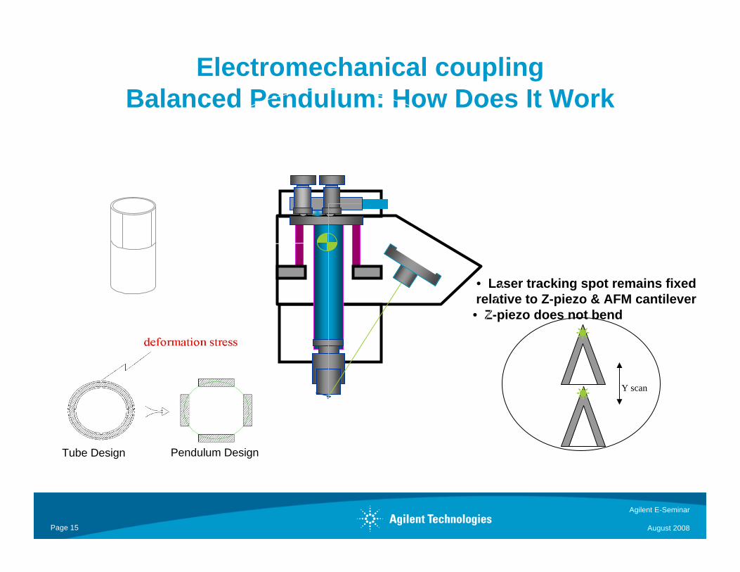
Electromechanical couplingBalanced Pendulum: How Does It Work
Y scan
• Laser tracking spot remains fixed relative to Z-piezo & AFM cantilever• Z-piezo does not bend
Tube Design Pendulum Design

Agilent E-Seminar
August 2008Page 16
RF to PNA
Load Diplexer
Scanner head With Conductive Tip
Early Design Suffers from Abrupt Localized Bend of Coax Connecting TIP to Diplexer
Coax from the Tip to diplexer

Agilent E-Seminar
August 2008Page 17
Distribution of Electromechanical Coupling Through Coaxial Loop
Diffusion of electrical/mechanical coupling with integration of enhanced VNA and Precision Machining
Half Wavelength Cable
Diplexer 50 Ohm CKT
Looped cable
Looped cable
Extraction tool
Conductive TipConductive Tip

Agilent E-Seminar
August 2008Page 18
Speedy Conductive Tip Replacement
Magnetic Jaw
RF Connection
Conductive Tip
Pt/Rb Cantilever
Alumina Carrier

Agilent E-Seminar
August 2008Page 19
DPMM Dopant Profile Measurement Module
DPMM approach:Use the Flatband transfer function
that is function of dopant density ( variable capacitor) that can be used as an AM mixer to modulate the reflected MW signal at the rate of Flatband drive frequency (<100 KHz). The said AM modulation index is function of the dopant density.

Agilent E-Seminar
August 2008Page 20
DPMM Block Diagram/Physical Realization
A
LO
A/D
Source
B
LO
A/D
Half wave lengthCoaxial resonator
50 Ohm
ProbeAMP
AMPAMP AMP
AMP
Signal outTo Lock in
RCVR IN
CPLR OUT
CPLR Thru
DPMM
dopant
Signal IN
Source Out

Agilent E-Seminar
August 2008Page 21
DPMM Internal Structure and as an add on Module to PNA
DPMM Internal MIC detail DPMM as an add measurement module to PNA
DPMM PNA PORT1
Agilent E-Seminar
August 2008Page 22
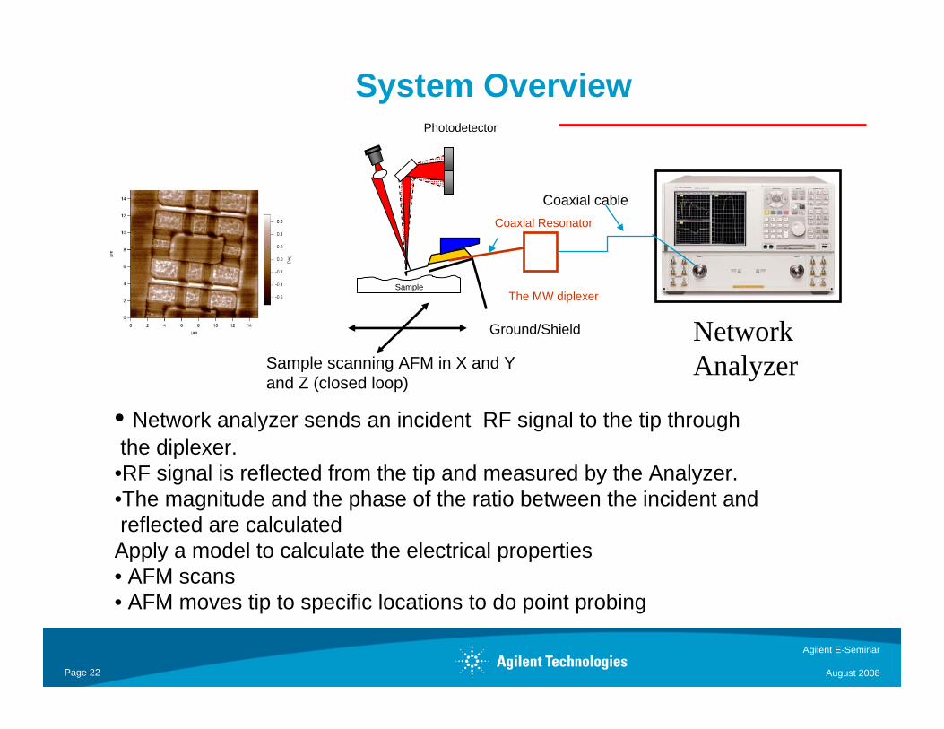
System Overview
Coaxial cable
Network Analyzer
• Network analyzer sends an incident RF signal to the tip throughthe diplexer.•RF signal is reflected from the tip and measured by the Analyzer.•The magnitude and the phase of the ratio between the incident andreflected are calculatedApply a model to calculate the electrical properties• AFM scans• AFM moves tip to specific locations to do point probing
Photodetector
Sample
Coaxial Resonator
The MW diplexer
Ground/Shield
Sample scanning AFM in X and Y and Z (closed loop)

Agilent E-Seminar
August 2008Page 23
SRAM Image

Agilent E-Seminar
August 2008Page 24

Agilent E-Seminar
August 2008Page 25
• Scanning only• qualitative• poor sensitivity• limited 1015-1020 Atoms/cm3• No Conductors/Insulators