Exno 5 Online Course Reservation System
14
ONLINE COURSE RESERVATION SYSTEM AIM To design an object oriented model for course reservation system. PROBLEM ANALYSIS AND PROJECT PLANNING: The requirement form the customer is got and the requirements about the course registration are defined. The requirements are analyzed and defined so that is enables the student to efficiency select a course through registration system. The project scope is identified and the problem statement is prepared. PROBLEM STATEMENT a. Whenever the student comes to join the course he/she should be provided with the list of course available in the college. b. The system should maintain a list of professor who is teaching the course. At the end of the course the student must be provided with the certificate for the completion of the course. SYSTEM REQUIEMENT SPECIFICATION GLOSSARY Generally a glossary is performed to define the entire domain used in the problem.It defines about the storage items that are familiar to the uses it provided these definitions and information about the attribute we are using in the particular project to the use, DEFINITIONS The glossary contain the working definition for the key concept in the course registration system COURSE The course which are offered by the institution
description
Online
Transcript of Exno 5 Online Course Reservation System

ONLINE COURSE RESERVATION SYSTEM
AIM
To design an object oriented model for course reservation system.
PROBLEM ANALYSIS AND PROJECT PLANNING:
The requirement form the customer is got and the requirements about the course registration are defined. The requirements are analyzed and defined so that is enables the student to efficiency select a course through registration system. The project scope is identified and the problem statement is prepared.
PROBLEM STATEMENT
a. Whenever the student comes to join the course he/she should be provided with the list of course available in the college.
b. The system should maintain a list of professor who is teaching the course. At the end of the course the student must be provided with the certificate for the completion of the course.
SYSTEM REQUIEMENT SPECIFICATION
GLOSSARY
Generally a glossary is performed to define the entire domain used in the problem.It defines about the storage items that are familiar to the uses it provided these definitions and information about the attribute we are using in the particular project to the use,
DEFINITIONS
The glossary contain the working definition for the key concept in the course registration system
COURSE
The course which are offered by the institution
COURSE CATALOG
These are all the course offered by the institution.
GRADE
The ranking of a particular student for a particular course offered

PROFESSOR
A person who reaches the course
CERTIFICATE
It is the proof for the completion the course
REGISTER
One who register the course for the student
OBJECTIVES
a. The main purpose of creating the document about the software is to know about the list of the requirement in the software project part of the project to be developed.
b. It specifies the requirement to develop a processing software part that completes the set of requirement.
SCOPE
a. In this specification, we define about the system requirements that are about from the functionality of the system.
b. It tells the users about the reliability defined in usecase specification
FUNCTIONALITY
Many members of the process line to check for its occurrences and transaction, we are have to carry over at sometimes
USABILITY
The user interface to make the transaction should be effectively
PERFORMANCE
It is the capability about which it can performed function for many user at sometimes efficiently (ie) without any ever occurrences
RELIABILITY
The system should be able to the user through the day to day transaction
USERCASE DIAGRAM
a. Use case is a sequence of transaction in a system whose task is to yield result of measurable value to individual author of the system
b. Use case is a set of scenarios together by a common user goal
c. A scenario is a sequence of step describing as interaction between a user and a system
DOCUMENTATION FOR USE CASE DIAGRAM
The use case diagram in the course registration system illustrates the sequence of steps followed in the system related to the actions of the system
LOGIN
This use case gives a entry to the student, professor and the register
SELECT COLLEGE AND COURSE
This use case list out the various courses offered by the institution
SUBMIT GRADES
This use case given the marks scored by the system
MAINTAIN PROFESSOR INFORMATION

This use case maintain the information about professor in the system
MAINTAIN STUDENT INFORMATION
This use case maintain the information about the professor in the system
CLOSE REGISTRATION
This use case describes the certification of the student when he/she finishes the course
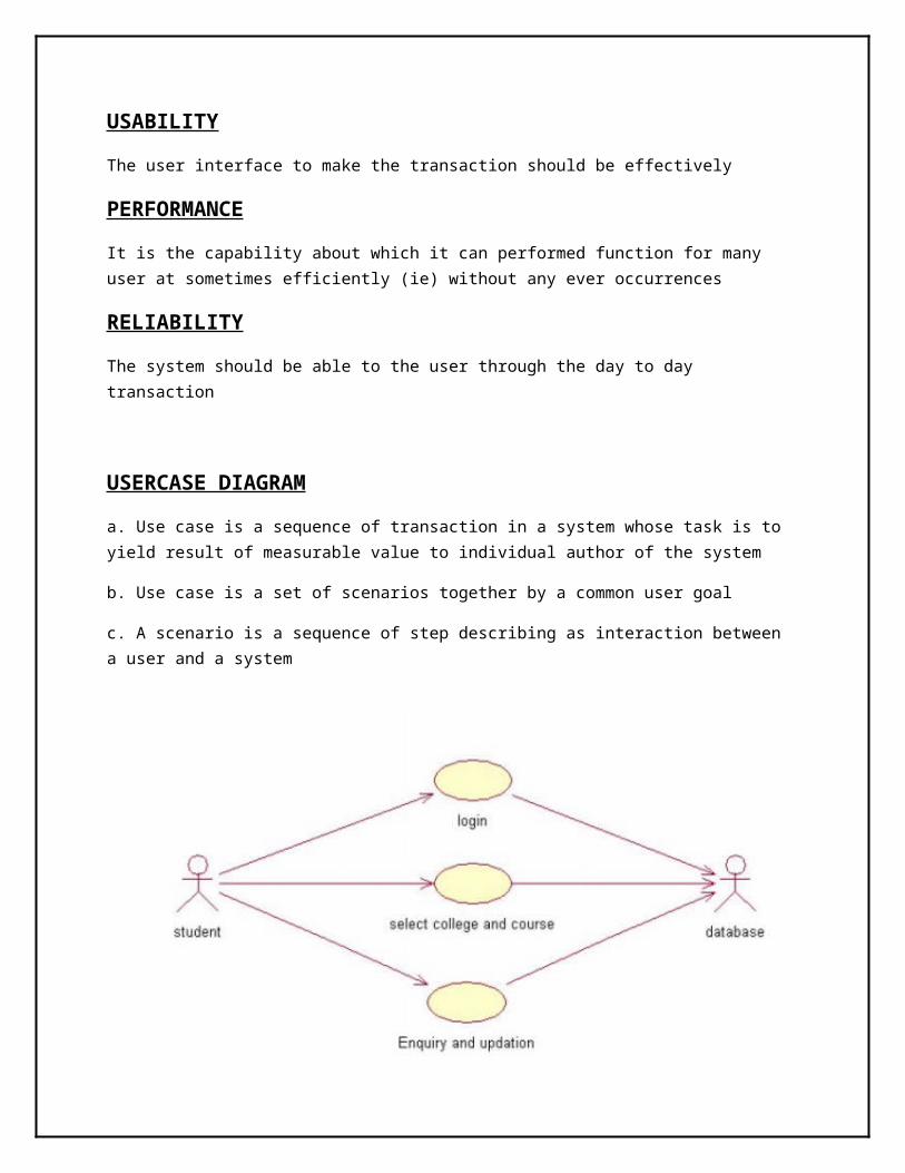
CLASS DIAGRAM:
A class diagram describes the type of objectors in the system the various kinds of static relationship that exist among them.
DOCUMENTATION OF CLASS DIAGRAM
a. The various classes involved in the system are registered student record, professor record all administration grade and close registration.
b. The student registers for the course.
c. After the course gets over each student will be asked to write a test.
d. Test mark is analyzed for the issue grade sheet after certification the registration of the student in closes.
SEQUENCE DIAGRAM
A sequence diagram is one that includes the object of the projects and tells the lifetimes and also various action performed between objects.

DOCUMENTATION OF SEQUECE DIAGRAM
a. The single use case in the course registration is taken and sequence of operation followed in the use case.
b. In the registration for the course use case diagram illustration on the process of registering and select a course.
c. The student enters the institution and gets a catalog about the list of course offered by the system.
d. The student can select a particular use case and registration for the course.
e. In the record use case submit grade at the end of each course each student will be asked to write a test. The result will evaluate for the issue of grade sheet and the grade are submitted.

COLLOBORATIION DIAGRAM
It is same as the sequence diagram that involved the project with the only difference that we give the project with the only difference that we give sequence number to each process.

DOCUMENTATION OF COLLOBORATION DIAGRAM
a. The diagram is also similar to sequence diagram but the difference is the various operations involves in the particular use case will be numbered. In this diagram the sequence of steps.
b. Getting the catalog to now about the course.
c. Selecting the course to study.
d. The final step is to register for the selected course.
e. In this submit grade use case the sequence of step is:
f. At the end of the course the student will write a test.
g. The test marks is validated to issue grade sheet
h. The certification is done to the student for the particular courses.
STATE DIAGRAM
It is a technique to describe the behavior of the system. It describes all the possible states that a particular object gets into the object oriented technique. State diagram are drawn for a single class to show to the lifetime behavior of a single objects
DOCUMENTATION OF THE STATE DIAGRAM
1. The various states are login student, register for course, maintain student and professor record, submit grade and close registration

2. The state diagram describes the behavior of the system
3. The main purpose of the system is to register the student for a course
4. After the student enrolls the course maintain the record for the student and professor
5. After the test being conducted each student mark will be analyzed for the grade sheet purpose
6. After the certification the registration is closed
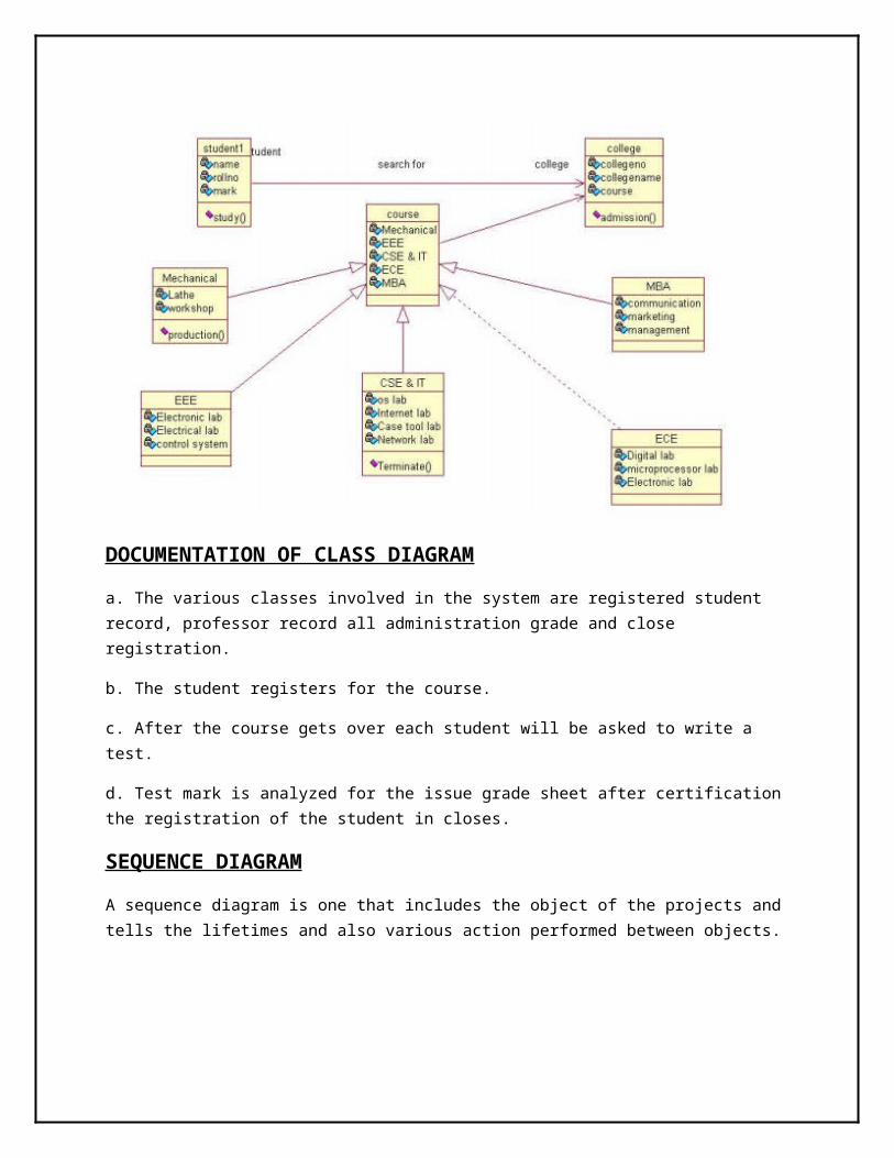
ACTIVIY DIAGRAM
It includes all the activities of particular project and various steps using join and Forks
DOCUMENTATION OF ACTIVITY DIAGRAM
a. The user login in to the course registration system
b. He/she selects a particular course form the list of available course
c. After the student register into the course the institution start the bill

Operation and record is maintain
d. The professor also start maintains the student record
e. At the end of the course based on the result grade the grade sheet or
Certificate is issued to the student
f. The registration is closed for the particular student
SOFTWARE DEVELOPMENT AND DEBUGING
a. Using rational rose software the software development and debugging is done.
b. This gives the over view of the project by the generation of definition and implementation of packages classes with all the relationship method and constructor.
c. We debug the diagram using log file and rectify the immoral relationship that exist among them and finally produce the project perfect diagram which gives exact print of the project.
SOFTWARE TESTING
a. In this step we prepare their plan for testing the diagram.
b. We perform the validation for the various data involved into the projects.
COMPONENT DIAGRAM
The component diagram is represented by figure dependency and it is a graph of design of figure dependency. The component diagram's main purpose is to show the structural relationships between the components of a system. It is represented by boxed figure. Dependencies are represented by communication association
DOCUMENTATION OF COMPONENT DIAGRAM
a. The components of the online course reservation are course details, login, and college details b. The course details, login and college details are dependent on the online course reservation are show by the dotted arrows
DEPLOYMENT DIAGRAM
It is a graph of nodes connected by communication association. It is represented by a three dimensional box. A deployment diagram in the unified modeling language serves to model the physical deployment of artifacts on deployment targets. Deployment diagrams show "the allocation of artifacts to nodes according to the Deployments defined between them. It is represented by 3-dimentional box. Dependencies are represented by communication association. The basic element of a deployment diagram is a node of two types
DEVICE NODE – A physical computing resource with processing and memory service to execute software, such as a typical computer or a mobile phone.
EXECUTION ENVIRONMENT NODE-- This is a software computing resource that runs within an outer node and which itself provides a service to host an execute other executable software element.
DOCUMENTATION OF DEPLOYMENT DIAGRAM
The device node is online course reservation and execution nodes are course details, login and college details
PACKAGE DIAGRAM
A package diagram is represented as a folder shown as a large rectangle with a top attached to its upper left corner. A package may contain both sub ordinate package and ordinary model elements. All uml models and diagrams are organized into package. A package diagram in unified modeling language that depicts the dependencies between the packages that make up a model. A Package Diagram (PD) shows a grouping of elements in the OO model, and is a Cradle extension to UML. PDs can be used to show groups of classes in Class Diagrams (CDs), groups of components or processes in Component Diagrams (CPDs), or groups of processors in Deployment Diagrams (DPDs).
There are three types of layer. They are
a. User interface layer
b. Domain layer
c. Technical services layer

DOCUMENTATION OF PACKAGE DIAGRAM
a. The three layer of online course reservation are user interface layer, domain layer and technical service layer a. The user interface layer- represent the user interface component such as web where the student login
b. The domain layer- has the major action such as select college, select course, request for seat and request for hostel.
c. Technical service layer-only authenticated user can access the technical service