
EXNER PROCESS EQUIPMENT - Insatech - forsiden of content III Table of content 1 Safety and...
55
EXNER PROCESS EQUIPMENT EXMATIC 460 Control unit Operating instructions
Transcript of EXNER PROCESS EQUIPMENT - Insatech - forsiden of content III Table of content 1 Safety and...
EXNER PROCESS EQUIPMENT
EXMATIC 460
Control unit Operating instructions
All brand and product names are trademarks of the company EXNER PROCESS EQUIPMENT Imprint Editor: EXNER PROCESS EQUIPMENT OHG Werner-von-Siemens-Straße 1 76694 Forst Germany Date of issue: 26/01/2009 © 2007, Dipl. -Ing. Detlef Exner As of 10/11/2008 File: EXmatic 460 BA eng 081110.doc All rights, including the rights in the translation, are reserved. The content of these operating instructions may only be reproduced with the written consent of EXNER PROCESS EQUIPMENT OHG, Forst, Germany. All technical information, drawings etc. are subject to the copyright law. Subject to technical modifications. This document was printed on chlorine and acid-free paper.

Table of content
III
Table of content
1 Safety and protection measures........................................................ 1
1.1 General notes on safety .........................................................................1
1.2 Intended use........................................................................................1
1.3 Danger areas and residual dangers ..........................................................2
1.4 Resources............................................................................................2
1.5 Personnel............................................................................................3
1.6 Disposal..............................................................................................3
1.7 Symbols and icons ................................................................................3
2 Product description .......................................................................... 5
2.1 Control unit EXMATIC 460 ........................................................................5
2.2 Process integration................................................................................6
3 Program functions ............................................................................ 9
3.1 Automatic start of cleaning .....................................................................9
3.2 Seal water ......................................................................................... 10
3.3 Cleaning program ............................................................................... 10
3.4 Pre- and After-Cleaning........................................................................ 12
3.5 Output signals .................................................................................... 13
4 Delivery.......................................................................................... 15
4.1 Delivery scope.................................................................................... 15
4.2 Delivery inspection.............................................................................. 15
5 Assembly........................................................................................ 17
5.1 Wall mounting.................................................................................... 17
5.2 Electric connections ............................................................................. 18
5.3 Pneumatic connections......................................................................... 19
5.4 Rinse valve connections ....................................................................... 20
6 Quick Setup.................................................................................... 21
6.1 Initial Operation.................................................................................. 21
7 Parameterization............................................................................ 29
7.1 Main Menu......................................................................................... 29
7.2 Automatic Mode.................................................................................. 30
7.3 Manual Mode ..................................................................................... 31
7.4 Parameters ........................................................................................ 32

Table of content
IV
7.5 System ............................................................................................. 38
8 Maintenance................................................................................... 45
8.1 Important notes on maintenance ........................................................... 45
8.2 Maintenance work............................................................................... 45
8.3 Disposal............................................................................................ 45
8.4 Resetting to Factory Settings................................................................. 46
9 Technical data ................................................................................ 47
9.1 Standards .......................................................................................... 47
9.2 Material............................................................................................. 47
9.3 Connected loads ................................................................................. 47
9.4 Ambient conditions.............................................................................. 48
9.5 Pneumatics ........................................................................................ 48
9.6 Rinse valves (option) ........................................................................... 48
9.7 Dimensions ........................................................................................ 49
9.8 Order structure EXmatic 460 ................................................................. 49
10 Spare parts and accessories............................................................ 51

1
1 Safety and protection measures
1.1 General notes on safety
The control unit EXMATIC 460 is designed in such a way that the
product does not present any risk if the operating instructions are
adhered to.
4 Read the operating instructions first.
4 Only assemble and operate the control unit if you have read
and understood all notes on safe and proper use.
4 Keep the operating instructions in order to consult it any
time.
4 Only operate the control unit and its accessories if they are
in an impeccable condition.
4 In addition, also observe the la ws, ordinances, regulations
and standards applicable in the country of use and at the
place of use.
1.2 Intended use
The control unit EXMATIC 460 is used for controlling pneumatic
retractable holders. The EXmatic 460 controls the movement of
the holder from the measurement position to the service position
and the process of automatic rinsing of the sensor in the rising
chamber of the holder.
The design of the control unit must be adjusted to the used
retractable holder.
The control unit must be maintained on a regular basis.
4 Establish a maintenance plan which is adjusted to your
process.
4 Only carry out maintenance work which is described in the
operating instructions!
1 Safety and protection measures
2
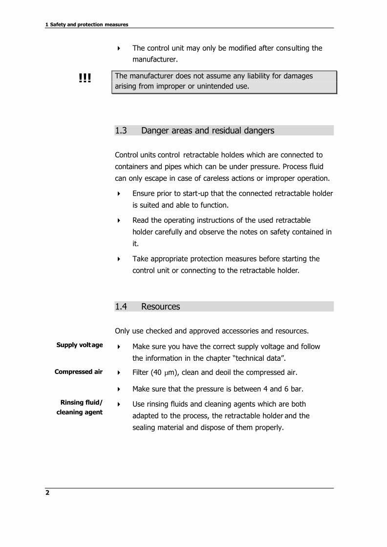
4 The control unit may only be modified after consulting the
manufacturer.
The manufacturer does not assume any liability for damages arising from improper or unintended use.
1.3 Danger areas and residual dangers
Control units control retractable holders which are connected to
containers and pipes which can be under pressure. Process fluid
can only escape in case of careless actions or improper operation.
4 Ensure prior to start-up that the connected retractable holder
is suited and able to function.
4 Read the operating instructions of the used retractable
holder carefully and observe the notes on safety contained in
it.
4 Take appropriate protection measures before starting the
control unit or connecting to the retractable holder.
1.4 Resources
Only use checked and approved accessories and resources.
4 Make sure you have the correct supply voltage and follow
the information in the chapter “technical data”.
4 Filter (40 µm), clean and deoil the compressed air.
4 Make sure that the pressure is between 4 and 6 bar.
4 Use rinsing fluids and cleaning agents which are both
adapted to the process, the retractable holder and the
sealing material and dispose of them properly.
!!!
Supply voltage
Compressed air
Rinsing fluid/
cleaning agent

1 Safety and protection measures
3
1.5 Personnel
Trained skilled workers may operate and maintain the control unit
only!
The operating personnel must wear suitable protective clothing
during start-up and maintenance work.
Observe the rules and regulations concerning safety at work
applicable in the country of use and at the place of use!
1.6 Disposal
Observe the rules and regulations concerning waste disposal
applicable in the country of use and at the place of use.
1.7 Symbols and icons
Icons and symbols in these operating instructions ensure a better
orientation.
Safety signs using the signal word DANGER! point out to danger
for life and limb as well as to the risk of considerable material
damages if the instructions are not observed.
Safety signs using the signal word CAUTION! point out to the
fact that materia l damages must be expected if the instructions
are not observed.
This is an important note!
This sign indicates that the working steps must be carried out in
the given order.
Qualification
Protective clothing
Accident
prevention rules
DANGER!
CAUTION!
!!!
R


5
2 Product description
2.1 Control unit EXMATIC 460
1 Operating panel
2 Function keys
3 Return button
4 ESC button
5 Main switch
Figure 1: Control unit outside
6 Terminal board
7 Indicator/pressure switch
8 Pilot valve
9 Input multi hose
Figure 2: Control unit inside
The control unit EXMATIC 460 can fully automatically control and
monitor the measuring and cleaning cycles of a pneumatic
retractable holder. For doing this, the cleaning times, measuring
intervals and the starting times can be parameterized and
adjusted to the respective specification.
The control unit monitors the respective position indication of the
retractable holder via integrated inputs.
View from outside
View from inside
Function
Input

2 Product description
6
Automatic cleaning can be started via an enlarged input.
The respective condition of the retractable holder and of the
control unit can be transmitted to a higher process control system
via three contact outputs.
The retractable holder and the cleaning valves for controlling the
cleaning solutions are connected to the control unit by means of
pneumatic hoses. This should be done with the adjusted
EXconnect multi hose.
2.2 Process integration
The control unit EXMATIC 460 is supplied with 24V DC and with
compressed air 4-6 bar. The connection of the retractable holder
and the cleaning and drain valves is realized by pneumatic hoses
which are gathered in a multi hose.
Figure 3: Process sequence
The respective status of the measuring unit (alarm status,
measuring status, cleaning status) can be transmitted to a higher
process control system by means of contacts.
A cleaning cycle can be started via an external trigger, e.g. from
the pH transmitter.
Output
Retractable holder
2 Product description
7
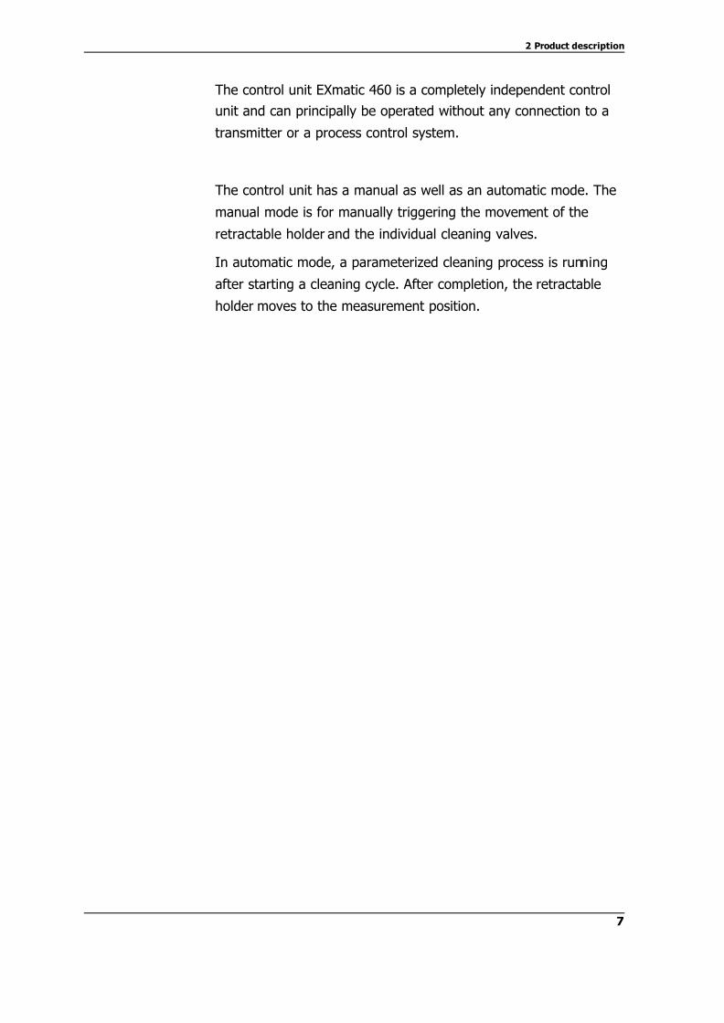
The control unit EXmatic 460 is a completely independent control
unit and can principally be operated without any connection to a
transmitter or a process control system.
The control unit has a manual as well as an automatic mode. The
manual mode is for manually triggering the movement of the
retractable holder and the individual cleaning valves.
In automatic mode, a parameterized cleaning process is running
after starting a cleaning cycle. After completion, the retractable
holder moves to the measurement position.


9
3 Program functions
3.1 Automatic start of cleaning
In principal, there are 3 different ways of starting an automatic cleaning cycle. They can also be combined in a useful manner. A recurring cycle is run via the internal clock (loop). In doing so,
after a parameterized measuring time, cleaning is started
automatically, e.g. every four hours. After completion of the
cleaning process, the retractable holder moves to the
measurement position and the cycle runs again.
Automatic cleaning is started at a specif ic point in time which can
be parametrized (Real Time Event), e.g. every day at 8.15 a.m.,
12 noon and 4.30 p.m.. After completion of the cleaning process,
the retractable holder moves to the measurement position and
stays there until the next Real Time Event starts.
Cleaning is started via an external trigger. After completion of the
cleaning and after opening the external trigger, the retractable
holder moves to the measurement position and stays there until
the external trigger is closed again.
As described, cleaning is carried out in a defined cycle (loop).
Further cleaning processes can additionally be started via an
external trigger and the retractable holder can be kept in the
cleaning position. This function is used if the sensor is to be
watered during operating lives and if the defined cycle is to be
interrupted, or if the sensor is to be pulled back into the rinsing
chamber for being protected while a strong agitator is running in
the container.
As described, cleaning is carried out at defined points in time
(Real Time Event). In addition, further cleaning processes can be
started via an external trigger and the retractable holder can be
kept in the cleaning position. This function is used if the sensor is
to be watered during operating lives and if the cycle is to be
interrupted. Or if the sensor is to be pulled back into the rinsing
Loop
Real Time Event
External Trigger
Loop + Trigger
Event + Trigger

3 Program functions
10
chamber for being protected while a strong agitator is running in
the container.
3.2 Seal water
For the short time during which the measuring window moves
over the sealing elements, when the retractable holder moves
from the measurement position to the cleaning position or back,
there is a connection between the process fluid and the rinsing
chamber. To ensure that as little process fluid as possible can
access the rinsing chamber and that the sealing elements are
additionally rinsed during this time, a seal water function can be
parameterized.
If the seal water function is active, the “Cleaning I” valve always
opens before the retractable holder is moved. This means that if
the water pressure connected to the “Cleaning I” valve is higher
than the process pressure, the water (seal water) runs through
the rinsing chamber to the process during the movement of the
retractable holder and thus prevents process fluid from accessing
the rinsing chamber. The sealing elements of the rinsing chamber
are rinsed at the same time.
The seal water function ensures a better cleaning of the sensor,
maintenance of the sealing elements and increases the operating
life of the sensor and of the sealings. The function should always
be active, if possible.
If you do not want seal water running to the process fluid or if this
is not admitted, the seal water function can also be deactivated.
The general function of the retractable holder and the control unit
is not impaired by that.
3.3 Cleaning program
As soon as a cleaning program is started (see 3.1), the following
functions are running one after the other:
Function
3 Program functions
11
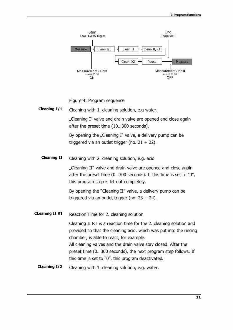
Figure 4: Program sequence
Cleaning with 1. cleaning solution, e.g water.
„Cleaning I“ valve and drain valve are opened and close again
after the preset time (10…300 seconds).
By opening the „Cleaning I“ valve, a delivery pump can be
triggered via an outlet trigger (no. 21 + 22).
Cleaning with 2. cleaning solution, e.g. acid.
„Cleaning II“ valve and drain valve are opened and close again
after the preset time (0…300 seconds). If this time is set to "0",
this program step is let out completely.
By opening the “Cleaning II” valve, a delivery pump can be
triggered via an outlet trigger (no. 23 + 24).
Reaction Time for 2. cleaning solution
Cleaning II RT is a reaction time for the 2. cleaning solution and
provided so that the cleaning acid, which was put into the rinsing
chamber, is able to react, for example.
All cleaning valves and the drain valve stay closed. After the
preset time (0…300 seconds), the next program step follows. If
this time is set to “0”, this program deactivated.
Cleaning with 1. cleaning solution, e.g. water.
Cleaning I/1
Cleaning II
CLeaning II RT
CLeaning I/2
3 Program functions
12
“Cleaning I” valve and drain valve are opened and close again
after the preset time (0…300 seconds). If this time is set to “0”,
this program deactivated.
By opening the “Cleaning I” valve, a delivery pump can be
triggered via an outlet trigger (no. 21 + 22).
If the sensor is not to be moved again into the process directly
after cleaning, the pause time is activated.
This is particularly recommended if the measuring medium is
especially aggressive and therefore the lifetime of the sensor is
especially short. In this case, short measuring intervals and long
pause times can minimize the dipping time of the sensor and thus
increase the lifetime.
The sensor remains in the rinsing chamber, all cleaning valves and
the drain valve remain closed. After the preset time (0…999
minutes), the sensor moves to the measurement position.
If the time is set to “0”, this program deactivated.
Measuring interval at parameterization “loop” or “loop + trigger”.
The sensor is moved to the measurement position and stays there
for the preset time (1…999 minutes). This time can be interrupted
in case of parameterization “loop + trigger” by an external trigger.
After this time has lapsed, the next cleaning cycle begins.
3.4 Pre- and After-Cleaning
The functions “Pre- and After – Cleaning“ serve to pre- and after-
clean the holder rinsing chamber respectively, in addition to the
normal cleaning cycle.
The function Pre-Cleaning is a rinsing function, which (pre-) cleans
the rinsing chamber, while the sensor is still in the measurement
position. Thus, it can be ensured during a hot water rinsing
procedure that the rinsing chamber is already heated before the
actual cleaning takes place and that hot rinsing medium is
Pause
Measure
Pre - Cleaning

3 Program functions
13
availa ble immediately. Cleaning the area of the rinsing chamber
before the process medium makes direct contact with the housing
parts is another application, at which the contact results from the
movement of the holder. This makes particular sense when the
function “Sealing water” cannot be used, e.g. with certain food
and pharmaceutical applications.
The function After-Cleaning is a rinsing function, which (after-)
cleans the rinsing chamber, while the sensor is already back at the
measurement position upon a normal cleaning procedure.
3.5 Output signals
The control unit has 3 output signals that can be used to signal
status messages to a superior process control system. The
following functions can be assigned to the corresponding output
signals.
Measurement / Hold
Measurement : This contact is used to signal that the current
measurement value can be used. The signal is set (+24VDC, max
100mA at contact terminal 31/32) when the holder is in
measurement position.
The signal is set when the holder has reached the measurement
position and the sealing water function has been terminated.
The signal is reset, 2 seconds before the beginning of a
cleaning cycle, including the sealing water function, or when the
holder is removed from the measurement position manually.
Hold : This contact serves for freezing the measurement value,
while the holder is not in the measurement position and, thus, the
measurement value displayed is not up-to-date. The signal is set
(+24VDC, max 100mA at contact terminal 31/32) when the holder
is not in the measurement position.
After- Cleaning
Output signal I
3 Program functions
14
The signal is set, 2 seconds before the beginning of a cleaning
cycle, including the sealing water function, or when the holder is
removed from the measurement position manually.
The signal is reset when the holder has reached the
measurement position and the sealing water function has been
terminated.
It is not possible to use both functions simultaneously!
Cleaning in operation
The signal shows that the unit is implementing a cleaning
function.
normal : The signal is set (+24VDC, max 100mA at contact
terminal 33/34) when the cleaning function is being implemented,
even during the pre- and after-cleaning functions.
inverse : Selecting this functions results in the signal being
inverted, i.e. the signal is not set when a cleaning function is
being implemented, even during the pre- and after-cleaning
functions. In all other cases the signal is set, active.
Alarm / Malfunction
The signal shows that a malfunction is present.
normal : The signal is set (+24VDC, max 100mA at contact
terminal 35/36) when the holder has not reached the
corresponding final position at this point in time or in case the
compressed air fails completely.
inverse : Selecting this functions results in the signal being
inverted, i.e. the signal is not set when a malfunction is present.
In all other cases the signal is set, active.
Output signal II
Output signal III

4 Delivery
15
4 Delivery
4.1 Delivery scope
The control unit is inspected in the factory and delivered ready for
installation in a packaging which optimally protects the control
unit.
The delivery consists of:
§ control unit EXMATIC 460
§ key for control cabinet
§ operating instructions
Depending on the version you have ordered, you also receive:
§ EXconnect multi hose (installed)
§ mounting angle for multi hose (installed)
Keep the control unit in the packaging. There, it is protected best until being assembled.
4.2 Delivery inspection
Before releasing the control unit for assembly, you must ensure
that:
Ø packaging and control unit are in an impeccable condition.
Ø the identification plate of the control unit corresponds to the
data in the order form.
!!!
R

4 Delivery
16
Figure 5: Identification plate
The identification plate is affixed to the inside of the cabinet door!
In case of questions, please contact your dealer.
17
5 Assembly
5.1 Wall mounting
Ensure that
Ø there is enough working space for operating the control unit.
Ø possible voltage-supplying units are disconnected from the
mains.
Ø you only use approved tools.
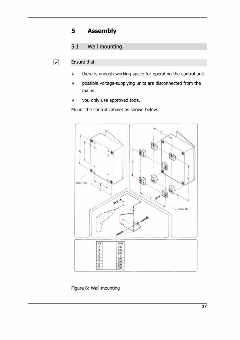
Mount the control cabinet as shown below:
Figure 6: Wall mounting
R

5 Assembly
18
5.2 Electric connections
The control unit must be disconnected from the mains and the
compressed air must be pressureless!
There is the risk for life and limb if the voltage supply is not
disconnected!
Connect the control unit according to the circuit diagram:
Ø6mm red
Ø6mm yellow
Ø6mm green
D1
D2
D3
D4
A1
A2
A3
A4
A5 A6Ø
4mm
blue
Ø4m
mbl
ack 60 61 62 63 64 65 66 67 68 69 70 71 72 73 74 75 76 77 78 79 80 81 82 83
AS
EXmatic460
Cle
an.p
ump
II
conn
ectin
g ho
seE
Xco
nnec
t 150
digital control unit
Ø6mm black
Ø6mm blue
Co 2 Co2
MS
1 2 11 12 21 22 23 24 31 32 33 34 35 36
+- +- +- +- +- +- +-
power distribution
Out
puts
igna
l IM
easu
rem
ent /
Hol
d
Out
puts
igna
l II
Cle
anin
g in
ope
ratio
n
Out
puts
igna
l III
Ala
rm /
mal
func
tion
exte
rnal
ST
AR
T
Pow
er s
uppl
y24
VD
C 3
0VA
Cle
an.p
ump
I
electrical wiring
pneumatical tubing
cleaning fluid tubing
Figure 7: Connection diagram
R
DANGER!

5 Assembly
19
Pin allocation:
Contact Description
1 Main Power supply 24VDC 30VA -
2 Main Power supply 24VDC 30VA +
11 Input Start signal (24VDC - selfpowered)
12 Input Start signal (24VDC + selfpowered)
21 Output 24VDC - max.80mA Clean Pump I
22 Output 24VDC + max.80mA Clean Pump I
23 Output 24VDC - max.80mA Clean Pump II
24 Output 24VDC + max.80mA Clean Pump II
31 Output 24VDC - max.100mA Measurement / Hold
32 Output 24VDC + max.100mA Measurement / Hold
33 Output 24VDC - max.100mA Service in operation
34 Output 24VDC + max.100mA Service in operation
35 Output 24VDC - max.100mA Alarm / Malfunction
36 Output 24VDC + max.100mA Alarm / Malfunction
5.3 Pneumatic connections
Multi hose
Control
connection
Hose
dim./colour
EXtract
connection Note
A1 black 6mm black 1 maintenance
A1 blue 6mm blue 2 measurement
A2 6mm red D4 drain valve
A3 6mm yellow D2 Cleaning I
A4 6mm green D3 Cleaning II
A5 4mm black 3 indicator
measurement
A6 4mm blue 4 indicator
maintenance
5 Assembly
20
Supply
Control
connection
Hose
Dimension Note
AS 4/6mm Filtered air 40µm, water and oil-free 4-6 bar
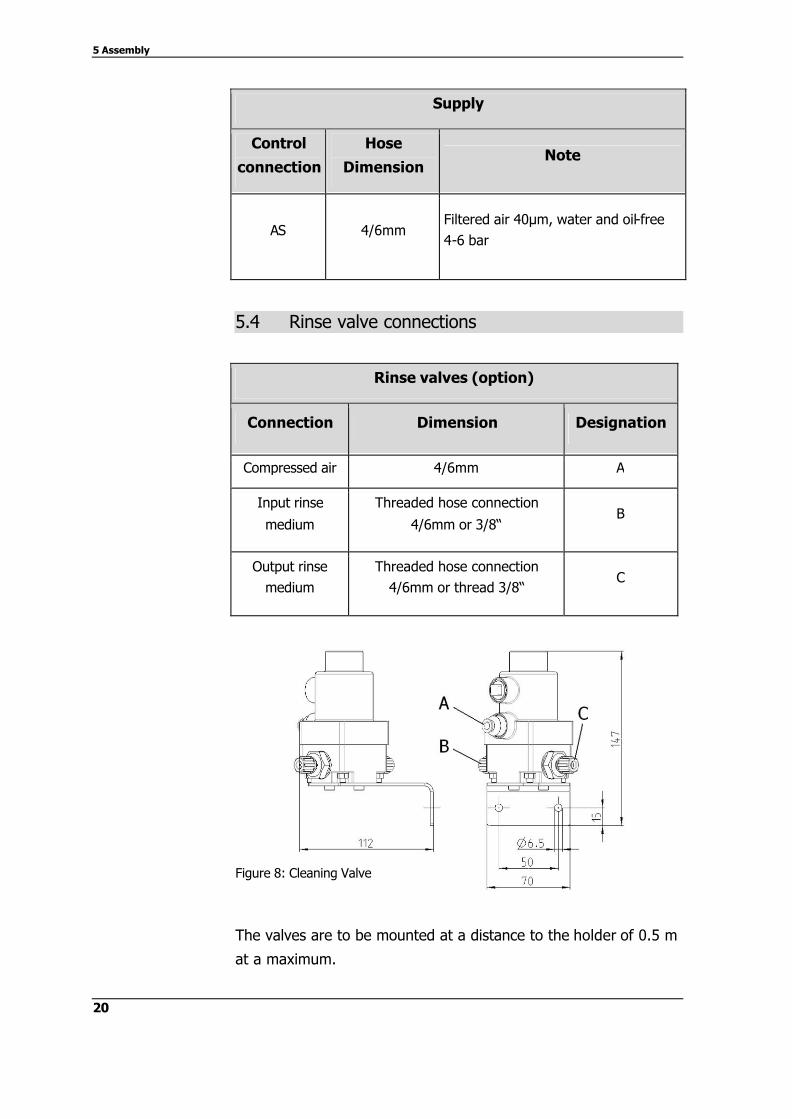
5.4 Rinse valve connections
Rinse valves (option)
Connection Dimension Designation
Compressed air 4/6mm A
Input rinse
medium
Threaded hose connection
4/6mm or 3/8“ B
Output rinse medium
Threaded hose connection 4/6mm or thread 3/8“
C
Figure 8: Cleaning Valve
The valves are to be mounted at a distance to the holder of 0.5 m
at a maximum.
6 Quick Setup
21
6 Quick Setup
$$
There is the risk of damaging the system or of the process
fluid or the cleaning solution leaking in an uncontrolled
manner!
Ø Wear suitable protective clothing
Ø Read the operating instructions
Ø Only have trained specialist personnel implement the
commissioning procedure of the system!
Ø Check all seals and all connections of the holder before moving
the same into the process
Please wear protective glasses and protective clothing when
commissioning the system!
The quick setup serves for quick parameterization of the control
unit during the commissioning procedure. The menu may be
completed once only. All settings can be retrieved and modified at
a later point in time in the Main Menu at Parameter and System.
(See chapter 7.)
6.1 Initial Operation
When activating the control unit for the first time, you will have
access to the Quick Setup menu.
Ø Using the Quick Setup you can implement all required
parameterization actions of the unit
Ø You will have access to the Quick Setup menu when
activating the control unit for the first time or when resetting
the unit back to factory settings. (Chapter 8.4)
Ø Instructions regarding the operation can be found in chapter
7
DANGER!
R

6 Quick Setup
22
The following display will be shown:
Set Clock
12 : 15 : 45 HH : MM : SS
UP DOWN NEXT (Further explanations in chapter 7.5)
Set the current time and exit the menu item using the ESC key.
The following display will be shown:
Set Date
31 . 03 . 08 DD : MM : YY
UP DOWN NEXT (Further explanations in chapter 7.5)
Set the current date and exit the menu item using the ESC key.
The following display will be shown:
Time Setup Clean I/1
10…300 Sec
010 Sec
UP DOWN (Further explanations in chapter 7.4)
Set the rinsing time for Clean I/1 and exit the menu item using
the ESC key.

6 Quick Setup
23
The following display will be shown:
Time Setup Clean II
0…300 Sec
000 Sec
UP DOWN (Further explanations in chapter 7.4)
Set the rinsing time for Clean II and exit the menu item using the
ESC key.
The following display will be shown:
Time Setup Clean II RT
0…300 Sec
000 Sec
UP DOWN (Further explanations in chapter 7.4)
Set the reaction time for Clean II RT and exit the menu item using
the ESC key.
The following display will be shown:
Time Setup Clean I/2
0…300 Sec
000 Sec
UP DOWN (Further explanations in chapter 7.4)
Set the rinsing time for Clean I/2 and exit the menu item using
the ESC key.

6 Quick Setup
24
The following display will be shown:
Time Setup Pause
0…300 Min
000 Min
UP DOWN (Further explanations in chapter 7.4)
Set the pause time and exit the menu item using the ESC key.
The following display will be shown:
Time Setup Measure
10…999 Min
060 Min
UP DOWN (Further explanations in chapter 7.4)
Set the measurement time and exit the menu item by using the
ESC key.
The following display will be shown:
Sealwater
Sealwater : YES
YES NO (Further explanations in chapter 7.4)
Parameterize the sealing water function and exit the menu item by
using the ESC key.
The following display will be shown:
Pre - Cleaning
Pre - Cleaning : NO
CL I CL I+II NO (Further explanations in chapter 3.4 /7.4)

6 Quick Setup
25
Parameterize the pre-cleaning function and exit the menu item
using the ESC key.
The following display will be shown:
After - Cleaning
After - Cleaning : NO
CL I CL I+II NO (Further explanations in chapter 3.4 / 7.4)
Parameterize the after-cleaning function and exit the menu item
using the ESC key.
The following display will be shown:
Operation Mode Real Time Event External Trigger ? Loop Event + Trigger Loop + Trigger
UP DOWN (Further explanations in chapter 7.4)
Parameterize the mode of operation and exit the menu item using
the ESC key.
The following display will be shown:
Real TiIme Event Event No.1 00:00 Event No.2 00:00 Event No.3 00:00 Event No.4 00:00 Event No.5 00:00
UP DOWN ? (Further explanations in chapter 7.4)
Enter the start time for the corresponding real time event and exit
the menu item using the ESC key.
6 Quick Setup
26
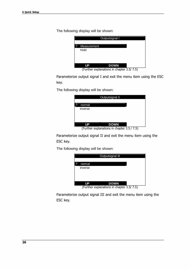
The following display will be shown:
Outputsignal I ? Measurement Hold
UP DOWN (Further explanations in chapter 3.5/ 7.5)
Parameterize output signal I and exit the menu item using the ESC
key.
The following display will be shown:
Outputsignal II ? normal inverse
UP DOWN (Further explanations in chapter 3.5 / 7.5)
Parameterize output signal II and exit the menu item using the
ESC key.
The following display will be shown:
Outputsignal III ? normal inverse
UP DOWN (Further explanations in chapter 3.5/ 7.5)
Parameterize output signal III and exit the menu item using the
ESC key.
6 Quick Setup
27
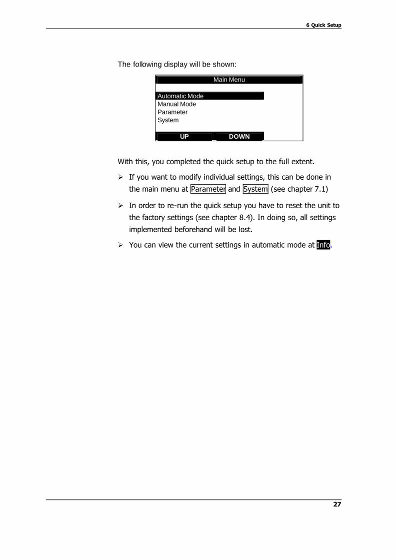
The following display will be shown:
Main Menu Automatic Mode Manual Mode Parameter System
UP DOWN
With this, you completed the quick setup to the full extent.
Ø If you want to modify individual settings, this can be done in
the main menu at Parameter and System (see chapter 7.1)
Ø In order to re-run the quick setup you have to reset the unit to
the factory settings (see chapter 8.4). In doing so, all settings
implemented beforehand will be lost.
Ø You can view the current settings in automatic mode at Info.


29
7 Parameterization
$$
There is the risk of damaging the system or that process
fluid or cleaning solution issues in an uncontrolled
manner!
Ø Wear suitable protective clothing
Ø Have the system only parameterized by instructed skilled
personnel!
Ø Inspect all sealings and all connections of the holder prior to
running the process
Wear protective glasses and protective clothing when you start
the system!
The control unit is generally operated as follows:
Main Menu Automatic Mode Manual Mode Parameter System
UP DOWN
Ø The upper line shows the current menu.
Ø The lower line shows the functions of the soft keys.
Ø The function which can be selected is shown invertedly in
the respective case and selected by means of the Enter
button.
Ø The ESC button brings you back one menu each time.
7.1 Main Menu
In the Main Menu, you can choose between the individual
processes.
DANGER!
R

7 Parameterization
30
Main Menu Automatic Mode Manual Mode Parameter System
UP DOWN
Ø When you select the Automatic Mode, the parameterized
automatic process in the control unit starts (chapter 7.2).
Ø When you select the Manual Mode, you reach the level for
manual operation (chapter 7.3).
Ø When you select Parameters , you reach the
parameterization (chapter 7.4).
Ø When you select System, you reach the system control
(chapter 7.5).
7.2 Automatic Mode
The parameterized process runs in automatic mode and the
display shows the following:
Automatic 12:22:17
* Measuring *
In 45 Min. Service
Info Para Stop
Ø The first line shows Automatic and the current time in
HH:MM:SS.
Ø The middle shows the current function in big letters.
Ø Below, the time remaining until the next function or action
starts is shown.
Ø The soft keys are assigned to the following parameters:
Info Para Stop

7 Parameterization
31
Shows information relating to the control unit via preset times, the
total time of a cleaning cycle and the state of the software.
Leads you to the parameterization of the cleaning and interval
times (chapter 6.4).
Automatic can be interrupted here.
By pressing the stop button, you can select between an
Emergency Stop and a “gentle” Stop.
In case of an Emergency Stop, the holder immediately moves to
the maintenance position, stays there and is not rinsed.
In case of stop, the holder moves to the maintenance position and
finishes with a parameterized rinsing process.
7.3 Manual Mode
In Manual Mode, the individual functions can be chosen manually.
If you have chosen the Manual Mode, you must now enter a pass
code:
Input Manual Code
0 0 0 0
UP DOWN NEXT
Enter the pass code by setting the digits by means of the UP or
DOWN button and by skipping to the right by means of the NEXT
button.
As soon as the pass code has been entered completely and
correctly, you confirm with Enter and reach the menu of the
manual mode. The following display is shown:
Info
Para
Stop

7 Parameterization
32
Manual Mode Measure Clean I Clean II
UP DOWN
Select the desired function by means of the soft keys and confirm
with Enter.
Manual Mode
Measure OFF
ON Stop
With the soft key ON, you switch the function on, with the soft
key OFF, you switch it off again.
With the soft key Stop, you stop the function in its original state.
ESC brings you back to the menu.
Process correspondingly for the functions Clean I and Clean II! For
the detailed description of the function, please refer to chapter 3.3
7.4 Parameters
You can parameterize the times and the functions of the control
unit in the parameters menu.
If you have chosen Parameter in the main menu or during the
automatic mode, you must now enter the pass code:
Input Parameter Code
0 0 0 0
UP DOWN NEXT
R

7 Parameterization
33
Enter the pass code by setting the digits by means of the UP and
DOWN buttons and by skipping to the right by means of the NEXT
button.
As soon as the pass code has been entered completely and
correctly, you confirm with Enter and reach the menu of the
parameters menu. The following display is shown:
Parameter Menu Service Time Setup Real Time Event Seal water Operation Mode
UP DOWN
Select the desired function via the soft keys and confirm with
Enter.
In the Service Time Setup the respective times of the functions
are set. The following display is shown:
Service Time Setup Clean I/1 010 Sec Clean II 000 Sec Clean II RT 000 Sec Clean I/2 000 Sec
UP DOWN ? The individual times are shown with the respective time which is
currently set. By means of the button ? you can access additional
times.
If you want to change times, select the desired time by means of
the soft keys and confirm with Enter. The following display is
shown:
Service Time
Setup
7 Parameterization
34
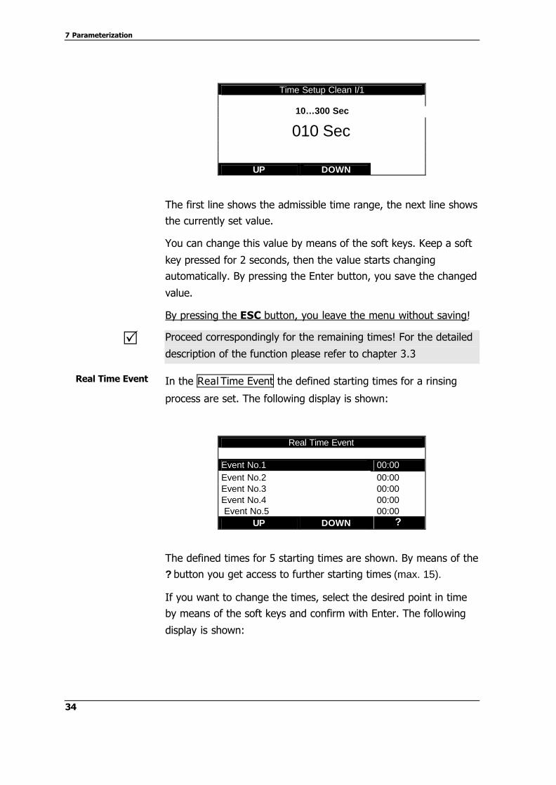
Time Setup Clean I/1
10…300 Sec
010 Sec
UP DOWN
The first line shows the admissible time range, the next line shows
the currently set value.
You can change this value by means of the soft keys. Keep a soft
key pressed for 2 seconds, then the value starts changing
automatically. By pressing the Enter button, you save the changed
value.
By pressing the ESC button, you leave the menu without saving!
Proceed correspondingly for the remaining times! For the detailed
description of the function please refer to chapter 3.3
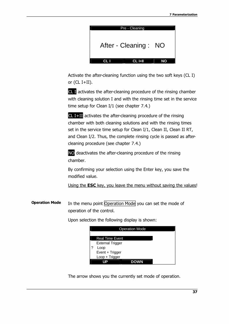
In the Real Time Event the defined starting times for a rinsing
process are set. The following display is shown:
Real Time Event Event No.1 00:00 Event No.2 00:00 Event No.3 00:00 Event No.4 00:00 Event No.5 00:00
UP DOWN ?
The defined times for 5 starting times are shown. By means of the
? button you get access to further starting times (max. 15).
If you want to change the times, select the desired point in time
by means of the soft keys and confirm with Enter. The following
display is shown:
R
Real Time Event

7 Parameterization
35
Real Time Event
00 : 00
UP DOWN NEXT
The first line shows the currently set starting time.
You can change this value by pressing the soft keys. Keep one
soft key pressed for 2 seconds and then, the value starts changing
automatically. By pressing the NEXT button, you switch between
hours and minutes and vice versa.
By pressing the Enter button, you save the changed value.
By pressing the ESC button, you leave the menu without saving!
Please proceed correspondingly for the remaining points in time!
For a detailed description of the function, please refer to chapter
3.1
In the menu point Seal water you can switch the seal water
function on and off.
Upon selection the following display is shown:
Seal water
Sealwater : YES
YES NO Switch the seal water function on (YES) or off (NO) by means of
the two soft keys.
By confirming with the Enter button, you save the changed value.
By pressing the ESC button, you leave the menu without saving!
You will find the exact functional description in chapter 3.2.
R
Seal water
R

7 Parameterization
36
Using the menu item Pre – Cleaning, you can activate or
deactivate the pre-cleaning function (pre-cleaning of the rinsing
chamber, see chapter 3.4).
If selected, the following display will be shown:
Pre - Cleaning
Pre - Cleaning : NO
CL I CL I+II NO
Activate the pre-cleaning function using the two soft keys (CL I) or
(CL I+II).
CL I activates the pre-cleaning procedure of the rinsing chamber
with cleaning solution I and with the rinsing time set in the service
time setup for Clean I/1 (see chapter 7.4.)
CL I+II activates the pre-cleaning procedure of the rinsing
chamber with both cleaning solutions and with the rinsing times
set in the service time setup for Clean I/1, Clean II, Clean II RT,
and Clean I/2. Thus, the complete rinsing cycle is passed as pre-
cleaning procedure (see chapter 7.4.).
NO deactivates the pre-cleaning procedure of the rinsing
chamber.
By confirming your selection using the Enter key, you save the
modified value.
Using the ESC key, you leave the menu without saving the values!
Using the menu item After - Cleaning, you can activate or
deactivate the after-cleaning function (after-cleaning of the rinsing
chamber, see chapter 3.4).
If selected, the following display will be shown:
Pre - Cleaning
After- Cleaning
7 Parameterization
37
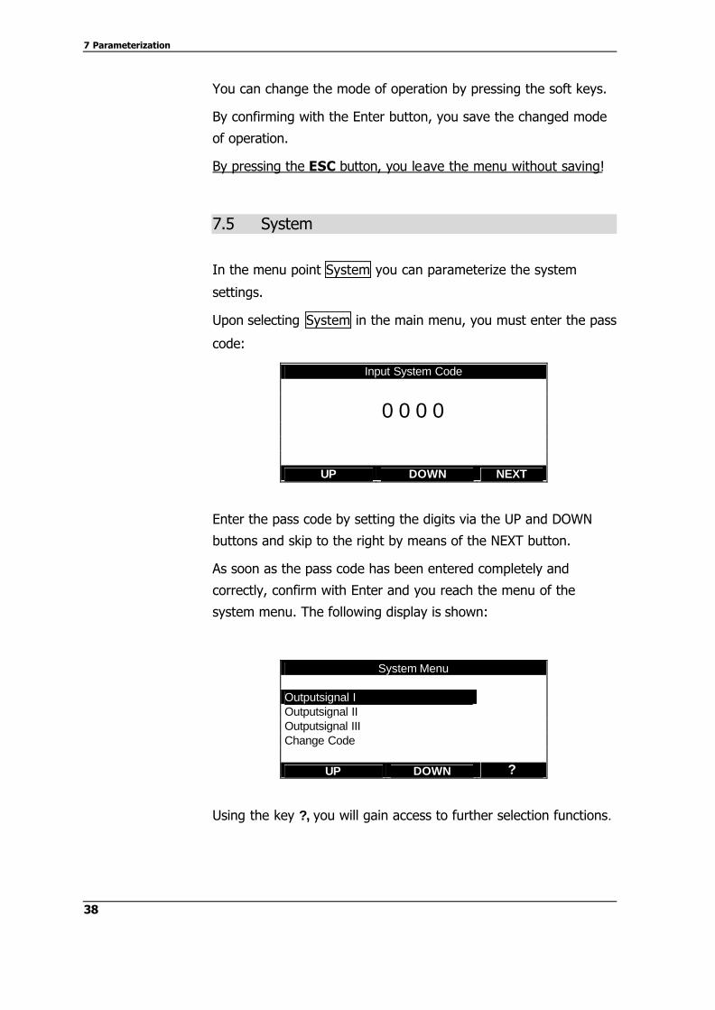
Pre - Cleaning
After - Cleaning : NO
CL I CL I+II NO
Activate the after-cleaning function using the two soft keys (CL I)
or (CL I+II).
CL I activates the after-cleaning procedure of the rinsing chamber
with cleaning solution I and with the rinsing time set in the service
time setup for Clean I/1 (see chapter 7.4.)
CL I+II activates the after-cleaning procedure of the rinsing
chamber with both cleaning solutions and with the rinsing times
set in the service time setup for Clean I/1, Clean II, Clean II RT,
and Clean I/2. Thus, the complete rinsing cycle is passed as after-
cleaning procedure (see chapter 7.4.)
NO deactivates the after-cleaning procedure of the rinsing
chamber.
By confirming your selection using the Enter key, you save the
modified value.
Using the ESC key, you leave the menu without saving the values!
In the menu point Operation Mode you can set the mode of
operation of the control.
Upon selection the following display is shown:
Operation Mode Real Time Event External Trigger ? Loop Event + Trigger Loop + Trigger
UP DOWN
The arrow shows you the currently set mode of operation.
Operation Mode
7 Parameterization
38
You can change the mode of operation by pressing the soft keys.
By confirming with the Enter button, you save the changed mode
of operation.
By pressing the ESC button, you leave the menu without saving!
7.5 System
In the menu point System you can parameterize the system
settings.
Upon selecting System in the main menu, you must enter the pass
code:
Input System Code
0 0 0 0
UP DOWN NEXT
Enter the pass code by setting the digits via the UP and DOWN
buttons and skip to the right by means of the NEXT button.
As soon as the pass code has been entered completely and
correctly, confirm with Enter and you reach the menu of the
system menu. The following display is shown:
System Menu Outputsignal I Outputsignal II Outputsignal III Change Code
UP DOWN ?
Using the key ?, you will gain access to further selection functions.

7 Parameterization
39
System Menue Set Clock Set Date Test OUT / IN
UP DOWN ?
Select the desired function by means of the soft keys and confirm
with Enter.
In the system mode Outputsignal I, the mode of operation of
output signal I can be set (see chapter 3.5)
The following display will be shown:
Outputsignal I ? Measurement Hold
UP DOWN
The arrow is to indicate the currently set mode of operation.
You can change the mode of operation by using the soft keys.
By confirming your selection using the Enter key, you save the
modified mode of operation.
Using the ESC key, you leave the menu without saving the values!
Measurement The signal is set when the holder has reached the
measurement position and when the sealing water function has
been terminated.
Hold The signal is set, 2 seconds before the start of a cleaning
cycle, including the sealing water function, or when the holder is
removed from the measurement position manually.
Output signal I
7 Parameterization
40
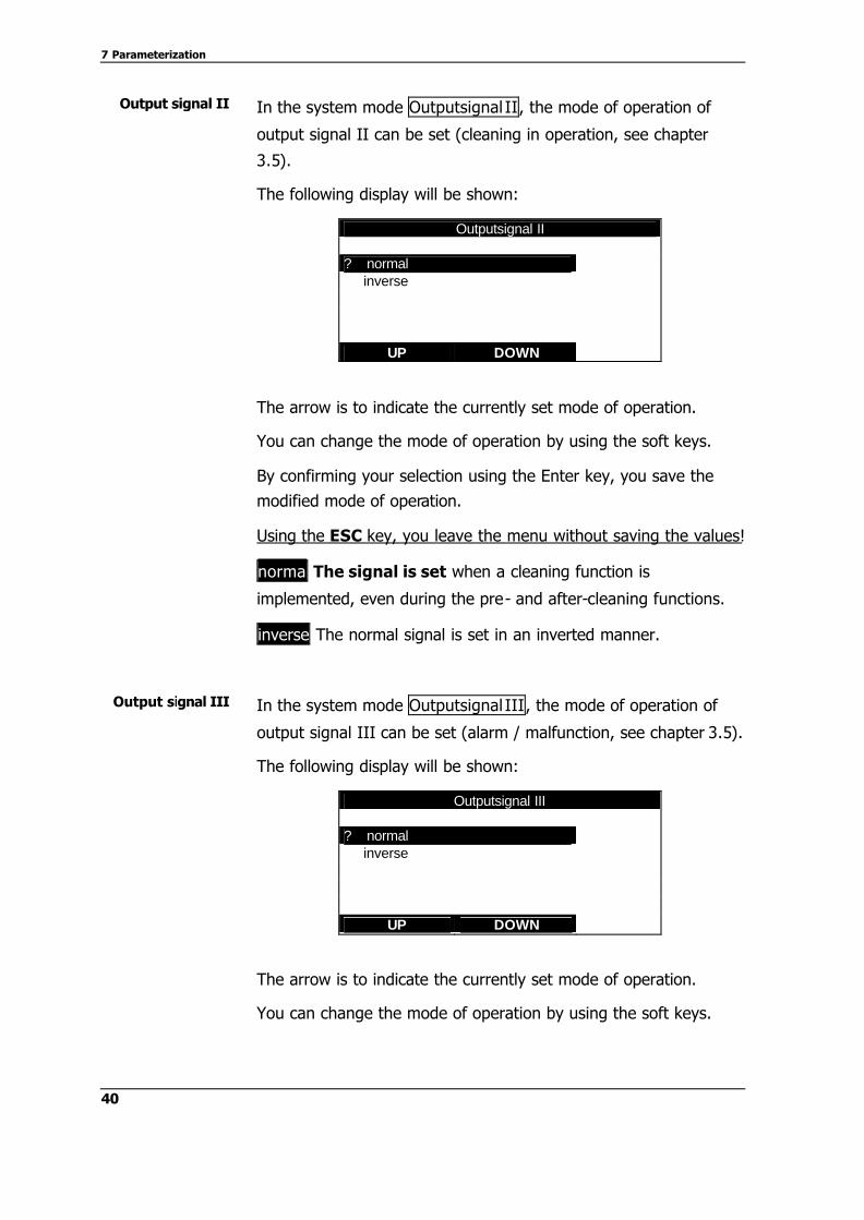
In the system mode Outputsignal II, the mode of operation of
output signal II can be set (cleaning in operation, see chapter
3.5).
The following display will be shown:
Outputsignal II ? normal inverse
UP DOWN
The arrow is to indicate the currently set mode of operation.
You can change the mode of operation by using the soft keys.
By confirming your selection using the Enter key, you save the
modified mode of operation.
Using the ESC key, you leave the menu without saving the values!
normal The signal is set when a cleaning function is
implemented, even during the pre- and after-cleaning functions.
inverse The normal signal is set in an inverted manner.
In the system mode Outputsignal III, the mode of operation of
output signal III can be set (alarm / malfunction, see chapter 3.5).
The following display will be shown:
Outputsignal III ? normal inverse
UP DOWN
The arrow is to indicate the currently set mode of operation.
You can change the mode of operation by using the soft keys.
Output signal II
Output signal III
7 Parameterization
41
By confirming your selection using the Enter key, you save the
modified mode of operation.
Using the ESC key, you leave the menu without saving the values!
normal : The signal is set when the holder does not reach its
corresponding extreme stop position or when the compressed air
fails completely.
inverse The normal signal is set in an inverted manner.
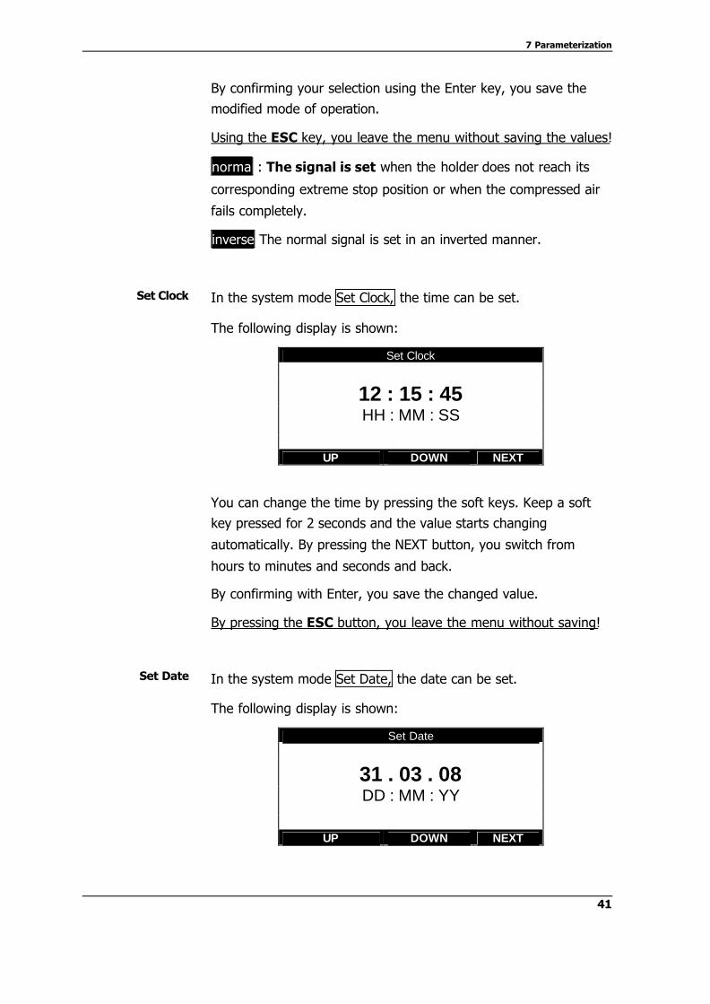
In the system mode Set Clock, the time can be set.
The following display is shown:
Set Clock
12 : 15 : 45 HH : MM : SS
UP DOWN NEXT
You can change the time by pressing the soft keys. Keep a soft
key pressed for 2 seconds and the value starts changing
automatically. By pressing the NEXT button, you switch from
hours to minutes and seconds and back.
By confirming with Enter, you save the changed value.
By pressing the ESC button, you leave the menu without saving!
In the system mode Set Date, the date can be set.
The following display is shown:
Set Date
31 . 03 . 08 DD : MM : YY
UP DOWN NEXT
Set Clock
Set Date

7 Parameterization
42
You can change the date by means of the soft keys. Keep a soft
key pressed for 2 seconds and the value starts changing
automatically. By pressing the NEXT button you can switch from
day to month and to year and back.
By confirming with Enter, you save the changed value.
By pressing the ESC button, you leave the menu without saving!
In the system mode Test OUT / IN, you can test the inputs and
the outputs of the control.
The following display is shown:
Test OUT / IN
Kanal : 1 2 3 4 5 6 7 OUT : 0 0 0 0 0 0 0
I
IN : 0 1 0 0 ON OFF ?
Select the channel via the ? button. The marking shows you the
channel you have selected. By pressing the soft keys ON and OFF,
you switch the outputs on (1) or off (0). The IN line shows you
the current status of the inputs.
By pressing ESC you leave the menu and the outputs are reset
again.
The outputs and the inputs are assigned as follows:
No. Output Connection
1 Holder drive 0=Service 1= Measurement 70/71
2 Drain valve 72/73
3 Cleaning valve I and Cleaning Pump I 74/75 21/22
4 Cleaning valve II and Cleaning Pump II 76/77 23/24
5 Output Measurement / Hold 78/79 31/32
6 Output Service 80/81 33/34
7 Output Alarm / malfunction 82/83 35/36
Test OUT / IN
7 Parameterization
43
No. Input Connection
1 Indication measurement 62/63
2 Indication service 64/65
3 Input Start signal 11/12 66/67
21/22 4 not assigned
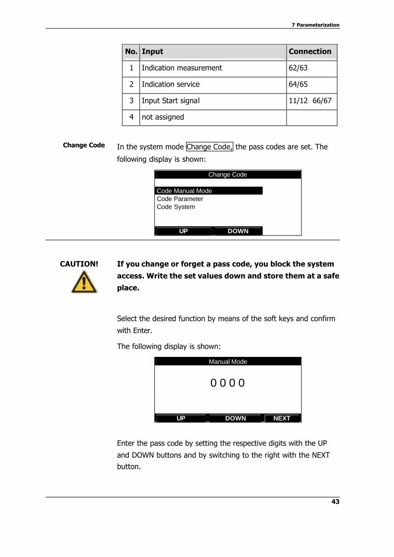
In the system mode Change Code, the pass codes are set. The
following display is shown:
Change Code Code Manual Mode Code Parameter Code System
UP DOWN
If you change or forget a pass code, you block the system
access. Write the set values down and store them at a safe
place.
Select the desired function by means of the soft keys and confirm
with Enter.
The following display is shown:
Manual Mode
0 0 0 0
UP DOWN NEXT
Enter the pass code by setting the respective digits with the UP
and DOWN buttons and by switching to the right with the NEXT
button.
Change Code
CAUTION!

7 Parameterization
44
As soon as the pass code has been entered completely and
correctly, save the new code by confirming with Enter.
By pressing the ESC button, you leave the menu without saving!
Proceed correspondingly for the remaining pass codes!
R
45
8 Maintenance
8.1 Important notes on maintenance
Ø Prepare a maintenance plan which is adjusted to your
process!
Ø Maintenance work may only be carried out by skilled
personnel.
Ø Always wear protective clothing during maintenance work.
Ø Only carry out maintenance work or repair which is described
in the operating instructions!
Ø Constructional modifications may only be carried out after
consulting the manufacturer.
8.2 Maintenance work
Yearly inspections.
Ø Check the compressed-air connections for tightness
Ø Check the multi hose connections for tightness and for a
stable fit at the holder and the control valves
Ø Retighten the clamps in the control cabinet
8.3 Disposal
Make sure that the control unit is free of hazardous and toxic
substances. The individual components must be disposed of
separately corresponding to their material.
Observe the rules and regulations relating to waste disposal which
are applicable in the country of use and at the place of use.
The packaging material is cardboard and can be disposed of as
waste paper.
R
Control unit
Packaging
8 Maintenance
46
8.4 Resetting to Factory Settings
By resetting the unit the factory settings, all settings and
parameterizations implemented beforehand will be lost!
Ø Switch off the control unit using the main switch.
Ø Hold the Enter key pressed for approx. 2 seconds while re-
activating the unit.
Ø You will automatically gain access the quick setup menu.
ATTENTION!

47
9 Technical data
9.1 Standards
Noise immune according to the standard EN 61000-6-2 Noise-suppressed according to the standard EN 61000-6-4 9.2 Material
Materials
Control cabinet
Casing glass-reinforced plastic
stainless steel option
Control unit glass-reinforced plastic
casing
plexiglass protection cover
9.3 Connected loads
Connected loads
Voltage supply 24V DC 30 VA
Input for external trigger 24V DC internal power supply for potential-free contact
Current consumption 0,65 A
Output for external relais, Cleaning Pump I and Cleaning Pump II
24V DC 80mA max.
Output for status and alarm contacts 24V DC 100mA max.
Triggering pneumatic valves 24V DC 80mA max.

9 Technical data
48
9.4 Ambient conditions
Temperature
Ambient temperature 0…+55°C
Transport and storage temperature -10…+60°C
Ambient
Relative humidity 10…95 % not condensing
Type of protection
Casing IP 54
Control unit with safety guard IP 54 with the safety guard closed
9.5 Pneumatics
Pneumatic hoses
outer ∅ inner ∅
for control air 6 mm 4 mm
for position indication 4 mm 2 mm
Compressed air
- filtered 40µm, water and oil-free
- 4 - 6 bar
- no permanent air consumption!
9.6 Rinse valves (option)
Connections
outer ∅ inner ∅
Compressed air 6 mm 4 mm
Rinse medium 6 mm 4 mm
9 Technical data
49
9.7 Dimensions
Dimensions
Plastic Stainless steel
Width 300 mm 300 mm
Height 400 mm 400 mm
Depth 250 mm 250 mm
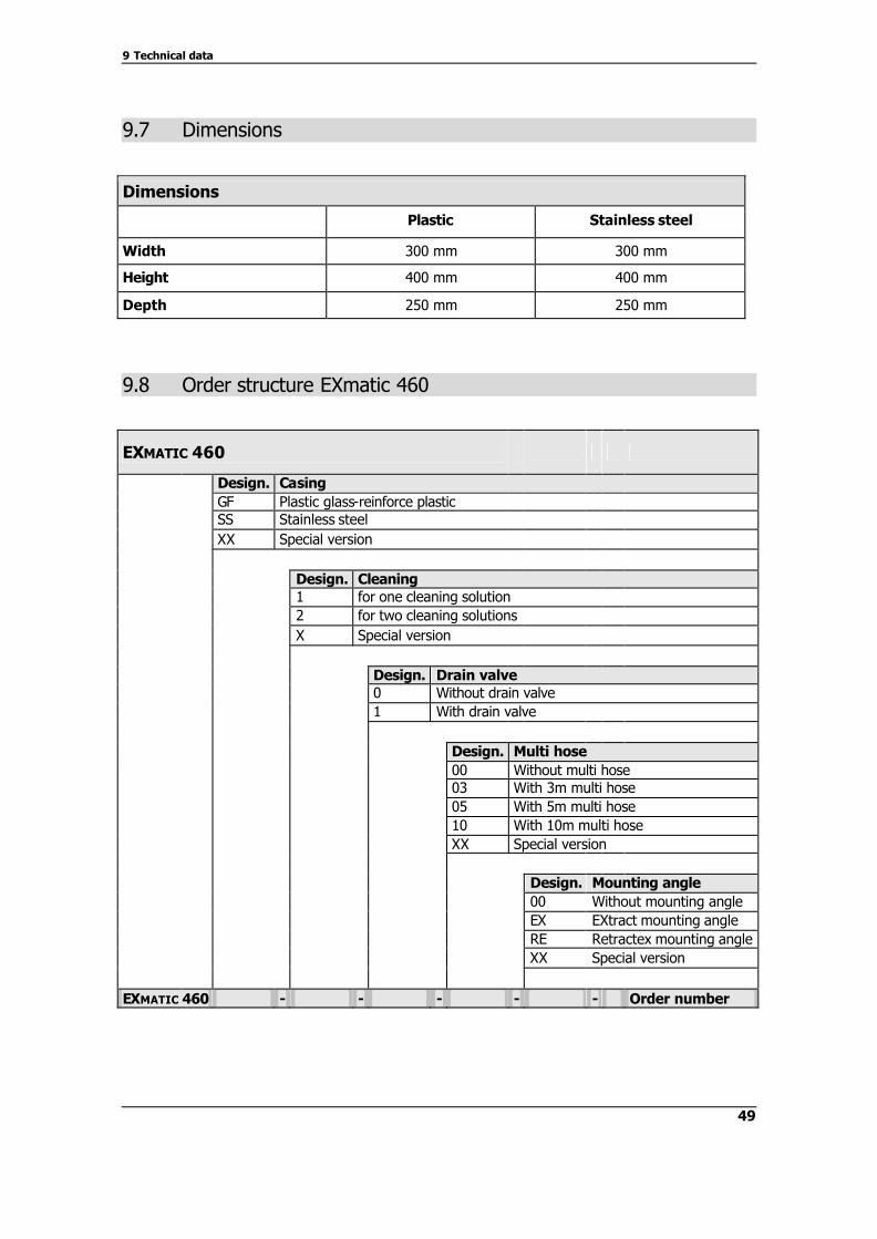
9.8 Order structure EXmatic 460
EXMATIC 460
Design. Casing GF Plastic glass-reinforce plastic SS Stainless steel XX Special version
Design. Cleaning 1 for one cleaning solution 2 for two cleaning solutions X Special version
Design. Drain valve 0 Without drain valve 1 With drain valve
Design. Multi hose 00 Without multi hose 03 With 3m multi hose 05 With 5m multi hose 10 With 10m multi hose XX Special version Design. Mounting angle 00 Without mounting angle EX EXtract mounting angle RE Retractex mounting angle XX Special version
EXMATIC 460 - - - - - Order number


51
10 Spare parts and accessories
Spare parts
CONTROL Spare part Order number
EXmatic 460 Electronic control unit 9-110-00-002
Solenoid valve 5/2-way G ¼“ 24VDC 3,8W (without plug and cable)
9-091-10-001
Solenoid valve 3/2-way G ¼“ 24VDC 3,8W (without plug and cable)
9-091-10-002
Plug with cable for solenoid valve 7-098-20-001
Pressure switch (indication) 9-096-00-001
Accessories
CONTROL CABINET Accessory Order number
wall mounting set for plastic cabinet 2-083-70-001
wall mounting set for stainless steel cabinet 2-083-70-002
pipe mounting set for cabinet (plastic/stainless steel) 2-083-70-003
CLEANING VALVES Accessory Order number
1 valve for cleaning solution or drainage 2-095-70-001
2 valves for cleaning solution and drainage, mounted to mounting angles with all connections and PTFE hose
2-095-70-002
Membrane valve PVDF/FPM G 3/8“, DN12 PN6, pneumatic, pressureless closed (NC) 3 valves for two cleaning solutions and drainage,
mounted to mounting angles with all connections and PTFE hose
2-095-70-003
Figure 9: Membrane valves as accessories for the retractable holder
Please indicate the serial number of your unit if you order spare
parts or accessories. !!!


