EXHIBIT 2 TECHNICAL REQUIREMENTS - P3 Virginia
620
Technical Requirements Exhibit 2 Execution Version Hampton Roads Bridge-Tunnel Expansion Commonwealth of Virginia Project No. 0064-M06-032 Virginia Department of Transportation EXHIBIT 2 TECHNICAL REQUIREMENTS [See attached]
Transcript of EXHIBIT 2 TECHNICAL REQUIREMENTS - P3 Virginia

Technical Requirements Exhibit 2 Execution Version
Hampton Roads Bridge-Tunnel Expansion Commonwealth of Virginia Project No. 0064-M06-032 Virginia Department of Transportation
EXHIBIT 2
TECHNICAL REQUIREMENTS
[See attached]

Technical Requirements Exhibit 2 Execution Version Technical Requirements
Hampton Roads Bridge-Tunnel Expansion Commonwealth of Virginia Project No. 0064-M06-032 Virginia Department of Transportation
EXHIBIT 2 Technical Requirements
List of Acronyms and Abbreviations Section 1. General Section 2. Project Management Section 3. Quality Management Section 4. Standards Section 5. Environmental Section 6. Document Control Section 7. Communications – Public Affairs Section 8. Surveying and GIS Section 9. Right of Way Section 10. Utilities Section 11. Security Section 12. Maintenance During Construction Section 13. Transportation Management Plan Section 14. Maintenance of Navigation Channel Section 15. Geotechnical – Roadways, Bridges, and Landside Structures Section 16. Marine Engineering Section 17. Roadway Design Section 18. Traffic Engineering Section 19. ITS and Toll Systems Section 20. Island Site Design Section 21. Bridges and Structures Section 22. Tunnel Approach Structures Section 23. Bored Tunnel Section 24. Geotechnical – Islands and Tunnels Section 25. Tunnel Wall Finishes Section 26. Mechanical Systems Section 27. Electric Power and Distribution Section 28. Fire Alarm, Detection, and Control Section 29. SCADA System Section 30. Communication Systems Section 31. Lighting Section 32. Aesthetics Section 33. Demolition Section 34. Commissioning, Operations, and Maintenance Section 35. Tunnel Support and Facility Buildings

Technical Requirements Exhibit 2 Execution Version List of Acronyms and Abbreviations
Hampton Roads Bridge-Tunnel Expansion Page 1 Commonwealth of Virginia Project No. 0064-M06-032 Virginia Department of Transportation
LIST OF ACRONYMS AND ABBREVIATIONS
Acronym/ Abbreviation Definition
% percent 2D two dimensional 3D three dimensional AACE American Association of Cost Engineers AAP AASHTO Accreditation Program AARB Virginia Art and Architectural Review Board AASHTO American Association of State Highway and Transportation Officials ABS Acrylonitrile butadiene styrene ABA Architectural Barriers Act ACI American Concrete Institute ACM asbestos containing material ADA Americans with Disabilities Act AFBMA Anti-Friction Bearing Manufacturers’ Associations AID automatic incident detection AISI American Iron and Steel Institute AMAG AMAG Technology AMCA Air Movement and Control Association International AMRL AASHTO Materials Reference Laboratory ANSI American National Standards Institute APE area of potential effects API American Petroleum Institute AR Plan Auditing and Non-Conformance Recovery Plan ASCE American Society of Civil Engineers ASCII American Standard Code for Information Interchange ASHRAE American Society of Heating, Refrigerating and Air-Conditioning Engr. AST above ground storage tanks ASTM American Society for Testing Materials ATC alternative technical concept ATMS Advanced Traffic Management System AWG American wire gauge AWS American Welding Society BCOM Bureau of Capital Outlay Management BMP best management practice BO burn out factor Br|R bridge rating CBR California bearing ratio CEM Coastal Engineering Manual CCPR cold central plant recycled CCT correlated color temperature

Technical Requirements Exhibit 2 Execution Version List of Acronyms and Abbreviations
Hampton Roads Bridge-Tunnel Expansion Page 2 Commonwealth of Virginia Project No. 0064-M06-032 Virginia Department of Transportation
Acronym/ Abbreviation Definition
CCTV closed-circuit television CD compact disc CFD computational fluid dynamics CFR Code of Federal Regulations CFRP carbon fiber reinforced polymer CHCC crushed hydraulic cement concrete CHRC criminal history records check CI critical infrastructure CII critical infrastructure information CII/SSI critical infrastructure information/sensitive security information CIMC Contractor Incident Management Coordinator CIP cast-in-place CIRIA Construction Industry Research and Information Association CLRP Constrained Long-Range Transportation Plan CO carbon monoxide CMAA Crane Manufacturer’s Association of America COMM fiber optic communications CMMS Computerized Maintenance Management Systems CNG compressed natural gas CPI consumer price index CPM critical path method CPSM Construction and Professional Services Manual CPT cone penetration test CPTED crime prevention through environmental design CPU central processing unit CQMP Construction Quality Management Plan CRR corrosion-resistant reinforcement CSU channel service unit CTB Commonwealth Transportation Board CV vessel collision forces D diameter DAS distributed antenna systems dBa weighted measure of sound; A-weighted decibels DBE Disadvantaged Business Enterprise DBPM Design-Builder’s Project Manager DCOA designated critical operations area DCS document control system DGN electronic drawing files DGS Department of General Services DHR Department of Historic Resources DIC distributed i/o cabinet

Technical Requirements Exhibit 2 Execution Version List of Acronyms and Abbreviations
Hampton Roads Bridge-Tunnel Expansion Page 3 Commonwealth of Virginia Project No. 0064-M06-032 Virginia Department of Transportation
Acronym/ Abbreviation Definition
DMS dynamic message sign DMV Department of Motor Vehicles DQMP Design Quality Management Plan DSRC dedicated short range communications DSU data service unit DTM digital terrain model DWL design total water level EA environmental assessment reevaluation EB eastbound EDMS electronic document management system EEO equal employment opportunity EFH essential fish habitat EIA Electrical Industries Association EM engineering manual
ENTRADA environmental; traffic data EPA Environmental Protection Agency EPB earth pressure balance EPSS emergency power supply system EPDM ethylene propylene diene terpolymer membrane EPR ethylene propylene rubber ERP Emergency Response Plan ESA1 Endangered Species Act ESA2 environmental site assessment ESC erosion and sediment control ESWP electrical system warranty period ETCS electronic tolling collection system EWL extreme water level EVA extreme value analysis EVP emergency vehicle preemption F Fahrenheit FAA Federal Aviation Administration FACP fire alarm control panes FAT factory acceptance test FCC Federal Communications Commission FDC field design change FEIS final environmental impact statement FEMA Federal Emergency Management Agency FFFS fixed fire-fighting system FHWA Federal Highway Administration FM frequency modulation FONSI Finding of No Significant Impact

Technical Requirements Exhibit 2 Execution Version List of Acronyms and Abbreviations
Hampton Roads Bridge-Tunnel Expansion Page 4 Commonwealth of Virginia Project No. 0064-M06-032 Virginia Department of Transportation
Acronym/ Abbreviation Definition
FOS factor of safety FRP fiber reinforced polymer FTP field trial program Gal. gallon GB gigabytes GBR geotechnical baseline report GDR geotechnical data report GEM grounding enhancement material GEP geotechnical exploration plan GER geotechnical engineering report GFCI ground fault circuit interrupter GIP Ground Improvement Plan GIS1 geographic information system GIS2 gas-insulated switchgear GOOSE generic object-oriented substation event GP general purpose GPM gallons per minute GPS global positioning system GRIT Guardrail Installation Training Manual GUI graphical user-interface HASS hydraulic analyzer of sprinkler systems H &HA hydrologic and hydraulic analysis HC high hydrocarbons HAZMAT hazardous materials HEC Hydraulic Engineering Circular HD high definition HDPE high density polyethylene HHC high-high hydrocarbons HMI human machine interface HOT/HOV high occupancy toll/high occupancy vehicle HPS high performance steel Hr hour HRBT Hampton Roads Bridge-Tunnel HRCS Hampton Roads Crossing Study HRHT Hampton Roads Harbor Tunnels HRSD Hampton Roads Sanitation District HRTOC Hampton Roads regional transportation operations center HW/D headwater/diameter HVAC heating, ventilation, and air conditioning Hz hertz ICS industrial control system

Technical Requirements Exhibit 2 Execution Version List of Acronyms and Abbreviations
Hampton Roads Bridge-Tunnel Expansion Page 5 Commonwealth of Virginia Project No. 0064-M06-032 Virginia Department of Transportation
Acronym/ Abbreviation Definition
IDSP Integrated Directional Signing Program IEC International Electrotechnical Commission IED intelligent electronic device IEEE Institute of Electrical and Electronics Engineer IESNA Illuminating Engineering Society of North America IHA incidental harassment authorization IIM or I&IM instructional and informational memorandum IM interim milestone IMP incident management plan IMR interchange modification report I/O input/output IPaC information, planning, and conservation system ISTMT in-situ temperature measurement test IT information technology ITD Information Technology Division ITT immersed tube tunnel IVST independent verification sampling and testing JPA Joint Permit Application KCMIL thousand circular mils KSI kilo pound per square inch kVA kilo-volt-ampere KW kilowatt LAN local-area network LAT luminaire ambient temperature factor Lbs pounds LCAM lane closure advisory management LCS lane control sign LDCF low density cementitious fill LED light emitting diode LEL lower flammable limit LFMC liquid tight flexible metal conduit LNTP limited notice to proceed LNTP1 first limited notice to proceed LLD lamp lumen depreciation LLF light loss factor LOD limits of disturbance LPPS low point pump station LRFD load and resistance factor design LTPP long term pavement performance LUS lane use signals MAPI messaging application programming interface

Technical Requirements Exhibit 2 Execution Version List of Acronyms and Abbreviations
Hampton Roads Bridge-Tunnel Expansion Page 6 Commonwealth of Virginia Project No. 0064-M06-032 Virginia Department of Transportation
Acronym/ Abbreviation Definition
MASH Manual for Assessing Safety Hardware MB megabyte Mbps megabits per second MCC motor control center MEPDG Mechanistic-Empirical Pavement Design Guide MFACC main fire alarm command center MFACP master fire alarm control panel MHHW mean higher high water MHR materials handling report MIMO/SISO multiple-input, multiple-output/single-input single-output MLLW mean lower- low water MM millimeter MMMBT Monitor-Merrimac Memorial Bridge-Tunnel MMP maintenance management plan MOI Manual of Instructions
MOVES motor vehicle emission simulator MOT maintenance of traffic MPH miles per hour MSDS material safety data sheet MSE mechanically stabilized earth MSL mean sea level MSWP mechanical system warranty period MUA master utility agreement MUTCD Manual on Uniform Traffic Control Devices MV medium volt MVD microwave vehicle detector MVDS microwave vehicle detection sensor MW megawatt NAD North American datum NAVD 88 North American vertical datum of 1988 NAVFAC Naval Facilities Engineering Command NBIS National Bridge Inspection Standards NCHRP National Cooperative Highway Research Program NCR non-conformance report NDC notice of design changes NEC National Electrical Code NECA National Electrical Contractors Association NEMA National Electric Manufacturers Association NEPA National Environmental Policy Act NERC North American Electric Reliability Corporation NESC National Electric Safety Code

Technical Requirements Exhibit 2 Execution Version List of Acronyms and Abbreviations
Hampton Roads Bridge-Tunnel Expansion Page 7 Commonwealth of Virginia Project No. 0064-M06-032 Virginia Department of Transportation
Acronym/ Abbreviation Definition
NESHAP National Emission Standards for Hazardous Air Pollutants NETA International Electrical Testing Association NFPA National Fire Protection Association NGS National Geodetic Survey NIMS National Incident Management System NIST National Institute of Standards and Technology NLEB northern long-eared bat NMFS National Marine Fisheries Service
NMS network management server NPS National Park Service NOAA National Oceanic and Atmospheric Administration NOx nitrogen oxide NRCS Natural Resources Conservation Service NRHP National Register of Historic Places NSBA National Steel Bridge Alliance NTC notice to commence NTCIP National Transportation Communications for Intelligent Transportation NTIS National Tunnel Inspection Standards NTP notice to proceed NWA navigable water activity OCR optical character recognition OIA owner’s independent assurance OIV occupant impact velocity OGDL open graded drainage layer OPC open platform communications OSHA Occupational Health and Safety Administration OTS over-the-shoulder OVST owner’s independent verification sampling and testing P2 pollution prevention PA Programmatic Agreement PABX private automatic branch exchange PACS physical access control systems PBX private automatic branch exchange PCF pounds per cubic foot PCR primary control room PCMS portable changeable message sign PCP public communications plan PDM precedence diagram method P.E. Professional Engineer PF power factor PGR production grouting report

Technical Requirements Exhibit 2 Execution Version List of Acronyms and Abbreviations
Hampton Roads Bridge-Tunnel Expansion Page 8 Commonwealth of Virginia Project No. 0064-M06-032 Virginia Department of Transportation
Acronym/ Abbreviation Definition
PIANC Permanent International Association of Navigation Congresses PJD preliminary jurisdictional determination PLC programmable logic controller PM particulate matter PMBOK Project Management Body of Knowledge PPE personal protection equipment PPM parts per million PPS portal pump station PPTA Public Private Transportation Act PS&E plans, specifications, and estimates PSF pounds per square foot PSI pounds per square inch PSN public safety network PTZ pan tilt zoom PVC polyvinyl chloride QA quality assurance QAM Quality Assurance Manager QC quality control QM quality management QMP quality management plan RACM regulated asbestos-containing material RDM Road Design Manual RFC released for construction RF radio frequency RFI request for information RFP request for proposal RLD Responsible Land Disturber RIO remote i/o RMP risk management plan ROD Record of Decision RPU remote processing unit RSDD room surface dirt depreciation factor RSL received signal level RTD resistance temperature detector RTRC reinforced thermosetting resin conduit RUMS Right of Way and Utilities Management System RWIS roadway weather information system SAS substation automation system SAV submerged aquatic vegetation SCADA supervisory control and data acquisition SCAT sewage collections and treatment

Technical Requirements Exhibit 2 Execution Version List of Acronyms and Abbreviations
Hampton Roads Bridge-Tunnel Expansion Page 9 Commonwealth of Virginia Project No. 0064-M06-032 Virginia Department of Transportation
Acronym/ Abbreviation Definition
SCR secondary control room Sec second (time) SEIS Supplemental Environmental Impact Statement SEPSS stored emergency power supply system SF square feet SFACC secondary fire alarm command center SFPC Statewide Fire Prevention Code SHPO State Historic Preservation Office SIA schedule impact analysis SICAM Synergetic Innovation Center for Advanced Materials SMACNA Sheet Metal and Air Conditioning Contractors National Association SMC stone materials control SMS security management system SO2 sulfur dioxide SOE support of excavation SOR schedule of record SP Special ProvisionSPCC spill prevention, control and countermeasures SPCN Special Provision Copied Note SPT standard penetration test SRPMS snow plowable raised pavement marker SSHS Saffir–Simpson hurricane scale SSPC Society for Protective Coatings STARS statewide agency radio system STEPS simulation of transient evacuation and pedestrian movements STRAHNET Strategic Highway Network SU single unit SUE subsurface utility engineering SWaM Small Woman-Owned and Minority Business SWM stormwater management SWPPP storm water pollution prevention plan T&E threatened and endangered TBM tunnel boring machine TBSC traffic barrier service concrete TCD traffic control devices TEU twenty-foot equivalent unit TIA Telecommunications Industry Association TIE ticket information exchange TMP transportation management plan TMC traffic management center TMS traffic management system

Technical Requirements Exhibit 2 Execution Version List of Acronyms and Abbreviations
Hampton Roads Bridge-Tunnel Expansion Page 10 Commonwealth of Virginia Project No. 0064-M06-032 Virginia Department of Transportation
Acronym/ Abbreviation Definition
TOC traffic operations center TOD tourist oriented directional signs TOMIE tunnel operations, maintenance, inspection and evaluation TOSAM Traffic Operations and Safety Analysis Manual TOP transportation operations plan TOYR time of year restrictions TTC temporary traffic control TTST tractor and semi-trailer TUST tunneling and underground space technology UPS uninterruptible power supply USBC Uniform Statewide Building Code UHF/VHF ultra-high frequency/ very high frequency UL Underwriters Laboratories URA Uniform Relocation Assistance and Real Property Acquisition Act U.S. United States USACE United States Army Corps of Engineers USBC Uniform Statewide Building Code USCG United States Coast Guard USDOT United States Department of Transportation USFWS United States Fish and Wildlife Service UST underground storage tank UV ultraviolet V volt VA Virginia VDEQ Virginia Department of Environmental Quality VDEM Virginia Department of Emergency Management VDGIF Virginia Department of Game and Inland Fisheries VDOT Virginia Department of Transportation VDS vehicle detection sensor VECP value engineering contractor proposal VEP value engineering proposal VF voltage factor VOC volatile organic compound VOSH Virginia Occupational Safety and Health VPN virtual private networkVPDES Virginia Pollutant Discharge Elimination System VSLS variable speed limit sign VSP Virginia State Police VTRC Virginia Transportation Research Council VWAPM Virginia Work Area Protection Manual WB westbound

Technical Requirements Exhibit 2 Execution Version List of Acronyms and Abbreviations
Hampton Roads Bridge-Tunnel Expansion Page 11 Commonwealth of Virginia Project No. 0064-M06-032 Virginia Department of Transportation
Acronym/ Abbreviation Definition
WBS word breakdown structure WIS wave information study WSP wireless service provider WOUS waters of the United States Yr. year

Technical Requirements Exhibit 2, Section 1 Execution Version General
Hampton Roads Bridge-Tunnel Expansion Page 1-1 Commonwealth of Virginia Project No. 0064-M06-032 Virginia Department of Transportation
GENERAL
1.1. Scope A. The Design-Builder shall be responsible for complying with all terms of the Agreement; the
HRCS Final SEIS, dated April 25, 2017; the ROD dated June 12, 2017; the HRCS EA , dated June 7, 2018; the FONSI, dated October 23, 2018; and shall thoroughly examine, review, and understand all terms prior to starting Work on the Project. The Design-Builder shall be responsible for determining and executing the full scope of the Project by undertaking a thorough examination of the Agreement, the Final SEIS, the ROD, the HRCS EA, the FONSI, and all other applicable documents, along with an understanding of the site conditions. All elements of Work revealed in this examination and determined to be necessary for the proper implementation of the Project shall be deemed to be included in the scope of the Design-Builder’s Work, whether or not specifically cited in the Agreement.
B. The Design-Builder shall not rely solely on the description contained in the Contract Documents to identify all project components to be designed, furnished, constructed, or installed by the Design-Builder. It is the Design-Builder’s responsibility to obtain clarification of any error, omission, conflict, or ambiguity relating to the scope of the Project or any Agreement requirement.
C. The preferred alternative from the ROD and FONSI were the basis for the Project development.
D. The Project is located on I-64 in the Cities of Hampton and Norfolk, beginning approximately 0.177 miles west of Settlers Landing Road (Western Terminus) and ending 0.289 miles east of Little Creek Road (Eastern Terminus).
E. The existing interstate configuration is as follows. In the eastbound direction, between the Western Terminus and the Eastern Terminus, the mainline roadway is a two-lane section in each direction and includes seven interchanges. The existing interstate is divided by a median barrier, from the Western Terminus to the northern trestles of the HRBT; then divided on trestles and tunnels across the Hampton Roads waterway; and then divided by a variable-width grass median, beginning on the Norfolk side after the southern trestles, to the Eastern Terminus.
F. The Project includes widening and reconfiguration of the existing interstate to accommodate two general purpose lanes, one HOT/HOV lane with a 3-foot buffer, and one part-time hard running shoulder in the eastbound and westbound directions; and new tunnel(s) that can accommodate four lanes of traffic. The proposed improvements include, but are not limited to:
1. New four-lane HRBT tunnel, tunnel system, and associated facilities.
2. New four-lane trestle(s).
3. Removal and replacement of all existing tunnel approach trestles.
4. Expansion of the existing North and South Islands of the HRBT.
5. Pavement widening to accommodate new lane configurations.
6. Full-depth hard running shoulders (inside) for part-time use.
7. Outside shoulders.
8. Retaining walls.
9. Sound barrier walls.

Technical Requirements Exhibit 2, Section 1 Execution Version General
Hampton Roads Bridge-Tunnel Expansion Page 1-2 Commonwealth of Virginia Project No. 0064-M06-032 Virginia Department of Transportation
10. Full-depth construction on mainline roadway pavement .
11. Milling and asphalt overlay.
12. Removal and replacement of the overpass bridge at South Mallory Street, including any necessary improvements or realignment of Mallory Street.
13. Bridge widening, repair, and replacement.
14. Entrance/exit ramp modifications.
15. Installation of storm drain pipes and SWM facilities.
16. Roadway signing, both ground-mounted and overhead.
17. Pavement marking, pavement markers, and delineators.
18. Roadway lighting.
19. Relocation of existing and installation of new ITS infrastructure and equipment.
20. Traffic signals.
G. It is noted that the description and length are approximate and are based on the RFP Concept Plans shown in the Disclosed Information. The final project length may vary depending on the Design-Builder’s final design; however, any change in the project limits requires acceptance by the Department.
H. The conceptual design contained in the Disclosed Information reflects a basic line, grade, typical sections, minimum pavement structures, major drainage structures, potential locations of SWM ponds, conceptual bridge and retaining wall locations, and general length and location of sound barrier walls. These elements are the basic project configuration and not all elements and requirements of the Project are illustrated within the RFP Concept Plans. The Design-Builder is responsible for final design in accordance with the Contract Documents. The PDF copy of the RFP Concept Plans shall supersede the electronic DGN contained in the RFP information package.
1.1.1. Anticipated Scope
A. The anticipated scope of work to be undertaken by the Design-Builder under the Agreement for the Project shall include, but is not limited to:
1. Survey.
2. Developing and completing the design through the Department authorization process.
3. Acquiring the necessary environmental permits, including USCG permit and Government Approvals.
4. Acquiring Right of Way, permanent and temporary easements.
5. Coordinating and performing, or causing to be performed, required utility relocations, additions, and adjustments.
6. Coordinating and cooperating with the Department’s existing tunnel operations.
7. Reporting procedures.
8. Roadway construction and widening.
9. Tunnel and tunnel systems design and construction.

Technical Requirements Exhibit 2, Section 1 Execution Version General
Hampton Roads Bridge-Tunnel Expansion Page 1-3 Commonwealth of Virginia Project No. 0064-M06-032 Virginia Department of Transportation
10. Reconstructing portions of existing mainline travel lanes, shoulders, and ramp acceleration/deceleration lanes.
11. Milling and overlaying or building up of existing pavement.
12. Clearing and grubbing.
13. Demolition or relocation of existing roadway assets.
14. Bridge demolition and bridge construction.
15. Bridge repair and rehabilitation.
16. Bridge fender construction and waterway navigation coordination.
17. Scour protection.
18. Bridge pier protection systems - new installation, repair, and/or replacement.
19. Guardrail/barrier planning, design, and installation.
20. Retaining wall - new installation, repair, and/or replacement.
21. Sound barrier wall - new installation, repair, and/or replacement.
22. Geotechnical work.
23. Planning, design, and construction of signs, sign structures, and foundations.
24. Traffic signal installations and modifications.
25. Roadway lighting.
26. ITS components including CCTV cameras, DMS, and COMM infrastructure for monitoring traffic conditions and safety.
27. System integration, testing, maintenance until Final Completion, and documentation.
28. Overhead signs, sign structures and other traffic control measures - new installations, repair, or replacement.
29. Coordination of work efforts with the toll operations concessionaire work efforts.
30. Planning, design, and construction of roadway and marine navigation lighting.
31. Traffic maintenance and management during all phases of construction.
32. Pavement markers and markings.
33. Completion of H&HA.
34. Planning, design, and construction of storm drainage.
35. Planning, design, and construction of SWM facilities.
36. Culvert inspection, repair, and rehabilitation.
37. Underdrain installation.
38. Planning and implementation of erosion and sediment control.
39. QA and QC for design and construction.
40. Stakeholder coordination and public outreach support.

Technical Requirements Exhibit 2, Section 1 Execution Version General
Hampton Roads Bridge-Tunnel Expansion Page 1-4 Commonwealth of Virginia Project No. 0064-M06-032 Virginia Department of Transportation
41. Overall project management and coordination with other active construction projects in the vicinity.
42. Planning, design, and construction of landscape architecture.
43. Potential hazardous materials remediation.
44. Mobilization, including providing and maintaining field or project offices.
45. Planning, design, and construction of tunnel support buildings.
46. Maintenance during construction.
47. Removal and disposal of all debris and materials from construction-related activities in accordance with VDOT Road and Bridge Specifications.
Descriptions and Technical Requirements of the anticipated Work are set forth in Technical Requirements 2 through 35.
1.1.2. Scope Option
A. Scope options shall be in accordance with Part 1, Section 1.1.2.
1.1.3. Anticipated Design Services
A. Design services shall address all items necessary for construction and operation of the completed facility. Design services are anticipated to include, but are not limited to, those services necessary to produce roadway, bridge, and tunnel construction plans and to the technical disciplines listed in this Technical Requirement, Section 1.1.1.
B. Other data collection and technical studies/reports anticipated include, but are not limited to:
1. Design criteria.
2. Geotechnical investigation.
3. Design quality management.
4. Public outreach support.
5. Design exceptions and design waivers.
6. Right of Way support.
7. Borings and analysis.
8. Materials analysis.
9. Pavement design.
10. Foundation design.
11. Traffic counts and analyses.
12. Utilities design and relocation.
13. Additional environmental studies and noise analyses (if warranted, as described in Technical Requirement 5).
14. H&HA.
15. Fire and life/safety analysis.
16. Tunnel space proofing.

Technical Requirements Exhibit 2, Section 1 Execution Version General
Hampton Roads Bridge-Tunnel Expansion Page 1-5 Commonwealth of Virginia Project No. 0064-M06-032 Virginia Department of Transportation
17. Systems integration.
18. Materials Handling Report.
19. Concept of Operations Report.
C. The Design-Builder should note that all work performed on the Project shall be completed using the English language and U.S. customary units of measure. The Design-Builder shall develop and adhere to a design submittal schedule. The Design-Builder shall adhere to the standards, references, and design criteria.
1.1.4. Anticipated Environmental Services
A. The Design-Builder shall meet all environmental commitments during design and construction, as applicable, as identified in the HRCS Final SEIS, the ROD, the HRCS EA, and the FONSI; the final Right of Way Authorization (EQ-201); the final PS&E Re-evaluation Authorization (EQ-200); and the final Environmental Certification/Commitments Checklist (EQ-103). All commitment compliance shall be supported by the appropriate documentation, to be provided by the Design-Builder to the Department. Further details are provided in Technical Requirement 5.
B. The Design-Builder shall acquire all water quality permits for the Project in the Design-Builder’s name (i.e., the Design-Builder shall be the Permittee) and shall provide for any necessary stream or wetland compensation required by permits to accomplish the Work.
C. Section 4(f) and 6(f) resources have been identified within the Project corridor which FHWA has made de minimis impact findings. These are reflected in the environmental documents and described in Technical Requirement 5, Sections 5.3.3 and 5.3.4. The Design-Builder shall continue to coordinate with all environmental agencies as the Project develops to ensure that all avoidance and minimization measures and other commitments regarding these resources are incorporated in the Project’s final design and implemented during construction.
D. The Design-Builder shall avoid all impacts to the environmentally sensitive areas identified in the environmental documents. All design and construction operations shall completely avoid these properties.
E. The following federally-listed species have been identified as potentially occurring in the project area and therefore potentially impacted by the Project:
1. Atlantic sturgeon, critical habitat, and other anadromous species.
2. EFH.
3. Listed sea turtles.
4. Wilson’s plover.
5. Gull-billed tern.
6. Piping plover.
7. Red knot..
8. NLEB
F. The following State-listed resources were also identified as potentially occurring in the project area and potentially impacted by the Project:
1. Mabee’s salamander.
2. Canebrake rattlesnake.

Technical Requirements Exhibit 2, Section 1 Execution Version General
Hampton Roads Bridge-Tunnel Expansion Page 1-6 Commonwealth of Virginia Project No. 0064-M06-032 Virginia Department of Transportation
3. Tricolored bat and little brown bat.
4. Benthic species.
5. SAV.
G. The Design-Builder shall conduct a Final Design Noise Analysis. For more information, see Technical Requirement 5.
H. The Design-Builder shall be responsible for compliance with pre-construction and construction-related environmental commitments, permit conditions, and for post-construction monitoring if required by regulatory agencies. The Design-Builder shall assume all obligations and costs incurred by complying with the terms and conditions of the permits and environmental certifications. Any fines assessed to the Project associated with environmental permits or regulatory violations are the financial responsibility of the Design-Builder.
I. Any changes in scope or project footprint from that contained in the Agreement proposed by the Design-Builder, and which are acceptable to the Department, may require additional environmental technical studies and analysis to be performed by the Design-Builder. All costs associated with those changes will be sustained by the Design-Builder. These technical studies and analysis shall be conducted in accordance with the professional standards and guidelines of each NEPA-related discipline, as well as the criteria described in Technical Requirement 5. The Department will be responsible for the coordination of any NEPA document re-evaluations with FHWA. The Design-Builder shall then carry out any additional environmental commitments that result from such coordination at its sole expense and at no additional cost or time delays to the Project.
1.1.5. Anticipated Right of Way and Utilities
A. The Design-Builder’s conceptual and final designs included in its Proposal shall be wholly contained within the proposed Right of Way limits shown on the RFP Concept Plans, except for temporary construction, permanent drainage and utility easements (other than permanent drainage easements for SWM facilities and where minor adjustments are required during the final design process, and only after approval by the Department),. Utility easements have not yet been identified or determined. Deviations from the proposed Right of Way limits shown on the RFP Concept Plans will be subject to Department acceptance in accordance with Part 4, Article 2.1.6. If the Design-Builder proposes a change to the Right of Way limits shown on the RFP Concept Plans, then this shall be considered a deviation from the Agreement documents.
B. The Design-Builder’s services shall include all Work necessary for Right of Way acquisitions and to perform utility coordination, relocations, or adjustments as required by the Project. All Right of Way costs (compensation paid to landowners for Right of Way or permanent easement) will be paid by the Department and shall not be included in the Design-Builder’s price. All costs for utility relocations, excluding betterments, shall be included in the Design-Builder’s price. Utility betterments shall not be included in the Design-Builder’s price, but shall be reimbursed to the Design-Builder through agreement with the requesting utility owner. Betterments shall be requested by, or approved by, the affected utility owner and shall meet Buy America requirements as described in Attachment 10 to Exhibit 26 of the Agreement.
C. Permanent aerial easements may be needed for the widening and new construction of structures over any municipal property. Acquisition of aerial easements shall be the responsibility of the Design-Builder.

Technical Requirements Exhibit 2, Section 1 Execution Version General
Hampton Roads Bridge-Tunnel Expansion Page 1-7 Commonwealth of Virginia Project No. 0064-M06-032 Virginia Department of Transportation
1.1.6. Anticipated Construction Services
A. The construction services to be undertaken by the Design-Builder for the Project are anticipated to include, but are not limited to:
1. Earthwork, roadway, tunnel, bridge, buildings, and structures (including all necessary dredging, excavation, foundation work, substructure work, and superstructure work).
2. Bridge fender construction, bridge pier protection systems, retaining walls, sound barrier walls, and waterway navigation signage/lighting.
3. Demolition and removal of portions of the existing pavements, milling and overlaying or building up of existing pavement, and full depth construction of new pavement.
4. Demolition and removal of existing structures, drainage, and SWM facilities.
5. Utility relocations/adjustments and coordination, MOT, overhead sign structures and other traffic control devices, ITS components, civil infrastructure, traffic signal modifications, lighting, erosion and sediment control; and compliance with all environmental requirements, commitments, and permit conditions as described in the environmental documents.
6. Tunnel support facilities (new and existing), including all architectural, mechanical, electrical, and structural meeting OSHA, NFPA, and NEC standards.
B. The Design-Builder shall provide construction engineering inspection and management, QA and QC, including plant QA inspection and testing, but excluding items listed in Technical Requirement 3, Section 3.1.2.
1.1.7. Scope Validation
A. The purpose of the scope validation clause is to provide the Design-Builder an opportunity to notify the Department of issues that are discovered during the post-Award review period that materially differ from what the Department provided in the RFP documents.
B. The clause is not intended to serve as a vehicle for the Design-Builder to raise issues that would ordinarily arise during the final design iteration process. The RFP documents are not represented to be complete. The Design-Builder is expected to make assumptions as to what they view as necessary to finalize the design and provide the Department with a firm price and schedule. The RFP documents contain numerous general depictions of existing conditions, which the Design-Builder is obliged to verify through field investigations and surveys before completing its final design of the Project and then integrating such design into its construction means and methods. It is the Design-Builder’s responsibility to consider all of this during the proposal process in developing its price and schedule. It is not envisioned that the final design development and related construction services (e.g., surveying and MOT transitions) would, on their own, create scope validation issues.
1.2. Standards and References A. The Standards identified in each Technical Requirement represent requirements that the Design-
Builder shall comply with in performing the Work.
B. The Design-Builder may utilize the engineering data provided in these Technical Requirements. However, the Design-Builder has the responsibility to validate any information it uses and has the ultimate responsibility for the performance of the Project.

Technical Requirements Exhibit 2, Section 1 Execution Version General
Hampton Roads Bridge-Tunnel Expansion Page 1-8 Commonwealth of Virginia Project No. 0064-M06-032 Virginia Department of Transportation
1.3. Technical Definitions A. North Trestle Minimum Low Chord Elevation – Elevation 15.6 ft (MSL); 15.35 ft (NAVD 88).
B. South Trestle Minimum Low Chord Elevation – Elevation 15.6 ft (MSL); 15.35 ft (NAVD 88).
C. Willoughby Bay Bridges Minimum Low Chord Elevation – Low Chord Elevation of the existing trestles.
1.4. Requirements A. The requirements subsections of the individual Technical Requirements establish the
Department’s expectations for the respective project elements. These include administrative, management, and technical considerations as deemed appropriate to the subject; and encompass performance specifications, design criteria, and directive instructions the Department deems best-suited to the subject. The Design-Builder shall develop its design and work packages, along with any special specifications and provisions necessary to complete the Work, in conformance with these Technical Requirements.
B. The Design-Builder shall be responsible for meeting all requirements and terms contained in these Technical Requirements, unless explicitly stated otherwise.
C. The specific requirements in these Technical Requirements may be more stringent and shall govern over the criteria given in the Standards; however, where a specific requirement in the Technical Requirements is more stringent than the criteria specified in a Standard, said specific requirement shall become the basis for determining compliance. Non-standard features that require justification and FHWA approval are defined as those not meeting the criteria cited in the Standards listed in these Technical Requirements.
1.5. Deliverables A. The deliverables subsections of the individual Technical Requirements establish the Department’s
expectations. These shall supplement the plan review cycles cited in this Technical Requirement, Section 1.7, and in Technical Requirement 3. The Design-Builder may provide deliverables for the Department’s consideration or consultation in addition to those requested in support of over-the-shoulder reviews. The Design-Builder shall include all formal and complete submittals in its review plan and submittal schedule and revise the review plan as necessary to incorporate sufficient advance notice to the Department. The schedule shall include pre-submittal meetings in advance of the submittals.
B. Unless otherwise indicated in a Technical Requirement, all deliverables shall be submitted in both electronic and hard copy format. Acceptable electronic formats include, but are not limited to, Microsoft Word, Microsoft Excel, ArcGIS, MicroStation, or searchable PDF files with no copy or password protection on the file content unless otherwise indicated in a Technical Requirement or a Standard cited in a Technical Requirement.
1.6. Plan Preparation
1.6.1. MicroStation and OpenRoads/GEOPAK
A. Upon request, the Design-Builder will be furnished with the following software and files which run in Windows7 or Windows10 only: OpenRoads (also known as GEOPAK SELECTseries 4), the current version used by the Department; MicroStation V8i (SELECTseries 4), the current version used by the Department; and the Department configuration and resource files, cell

Technical Requirements Exhibit 2, Section 1 Execution Version General
Hampton Roads Bridge-Tunnel Expansion Page 1-9 Commonwealth of Virginia Project No. 0064-M06-032 Virginia Department of Transportation
libraries, and plan and profile design files used to develop the RFP Concept Plans, including aerial images, if available, and survey files.
1.6.2. Software License Requirements
A. The Department has an enterprise license subscription agreement with Bentley Systems which provides maintenance and licenses for MicroStation and OpenRoads/GEOPAK. The VDOT CADD Support group provides technical support for these licensed software packages. The software is issued for the duration of each individual active project contract. This project is eligible for the software license(s).
B. The Department will furnish a license or other access means for all the software products the Department makes available to the Design-Builder. The license or access means will be supplied upon request by the Design-Builder, based on the data provided on a completed VDOT Software and License Request Form, LD-893, and subsequently reviewed and accepted by the Department.
C. The license or access means are provided for use on the Project detailed on the request only for the duration specified for the Project. Any adjustment made to the Project schedule will be taken into consideration in adjusting the time the license or access means is available. Justification for the number of license(s) requested shall include the estimated number of total computer hours for the task of design, detailing, related project management, and other computer-based engineering functions requiring the software requested.
D. The appropriate use of the license or access means provided to the Design-Builder shall become the responsibility of the Design-Builder, regardless of who on the team uses it. The Design-Builder shall be responsible for keeping track of the license or access means provided to them or a team member and, upon completion of the Project, for the prompt notification to the VDOT CADD Support section of project completion and removal of the software from any system used solely for the Project for which it was obtained.
E. The Design-Builder shall provide a minimum 3 days of training to the Department for any software for which VDOT does not have a license and which is proposed for use to complete the design or modeling of structures, bridges, tunnel approach sections, or tunnel sections. The Design-Builder shall submit a licensed English version of the software, including all manuals, to the Department.
1.6.3. Drafting Standards
A. All plans shall be prepared in U.S. customary units and in accordance with the VDOT Road Design Manual, VDOT CADD Manual, VDOT IIMs, and VDOT Manual of the Structure and Bridge Division, Part 2.
1.6.4. Electronic Files
A. The Design-Builder shall submit all plans in accordance with the Department’s policies and procedures (Right of Way or design, released for construction submittals, and As-Built Drawings) in electronic format using the provided CADD software. Files shall be submitted in both MicroStation DGN and Adobe PDF formats, by way of the VDOT ProjectWise Web Client.
B. The Design-Builder shall complete forms ITD-36E (VDOT Information Security Agreement) and LD-899 (VDOT Request for Access to the Location and Design ProjectWise Site) for access to the ProjectWise Web Client. The Department will furnish electronic files of all applicable standard detail sheets upon request by the Design-Builder. The files will use standard VDOT cell libraries, level structures, line types, text fonts, and naming conventions as described in the most

Technical Requirements Exhibit 2, Section 1 Execution Version General
Hampton Roads Bridge-Tunnel Expansion Page 1-10 Commonwealth of Virginia Project No. 0064-M06-032 Virginia Department of Transportation
recent version of the VDOT CADD Manual and the VDOT Manual of the Structure and Bridge Division, Part 2. Files furnished to the Design-Builder in electronic format shall be returned to the Department and removed from the Design-Builder’s and its designer’s computer equipment upon completion of the Project.
C. The Design-Builder shall create a 3D Model for each work package, developing a single cohesive 3D Model for proposed conditions once all work packages have been approved. A 4D Model and 4D Animations shall supplement the 3D Model to visualize planned work correlating to the approved Baseline Schedule and Schedule Updates. The models will supplement plan reviews and will be used to coordinate, monitor and validate progress for schedule updates. The Design-Builder shall develop, maintain and provide the models and other deliverables with the Special Provision for 3D and 4D Model Requirements.
1.7. Plan Submittals
1.7.1. General
A. Plans may be submitted for review and consideration in logical subsections (such as from bridge to bridge) or consisting of work packages such as: 1) clearing and grubbing along with erosion and siltation control, 2) grading and drainage, 3) final roadway, and 4) traffic control. Individual bridge or tunnel plans may be submitted in logical components such as: 1) substructure, 2) superstructure, 3) tunnel liner, 4) tunnel interior structure. A submittal schedule and planned breakdown of work packages shall be submitted to the Department for review and approval as part of the Baseline Schedule. The Department has the right to reject planned subsections that divide systems (e.g., drainage, tunnel systems) in a manner that makes compliance difficult to confirm. The Department will coordinate with the Design-Builder to determine priorities and expedite reviews where the Department and Design-Builder determine it is mutually feasible and beneficial. In order to expedite reviews to assist the Design-Builder other reviews may be impacted as agreed to. Implementation of expedited reviews and their consequences shall be agreed to and coordinated proactively along with design schedules, priorities and changes on a weekly basis. Submittals shall be planned to minimize the number of overlapping concurrent reviews. Where three or more overlapping concurrent submittals proposed in a week that affect a specific discipline such as geotechnical, drainage, structures, and/or systems, then they shall be planned and agreed to in advance as part of the weekly coordination and monthly progress meeting’s schedule review as noted in Technical Requirement 2, Section 2.4.
B. Supporting documentation for planned submittals shall be determined prior to the submittal through coordination between the Design-Builder and the Department. This will be part of the monthly progress meeting documentation as noted in Section 1.7.1.C below. Each submittal shall be accompanied at a minimum by 1) a VDOT LD-436 QC Checklist or otherwise agreed upon checklist, filled out as appropriate for the specific submittal, and 2) a written notice signed by the Design-Builder’s Design Manager that includes the following:
1. The logical subsections or work packages for which review, and consideration is being requested.
2. Certification that the submittal has been checked and reviewed in accordance with the Design-Builder’s accepted QA/QC plan along with supporting documentation of the certification as defined in Technical Requirement 3, Section 3.1.1.
3. Certification that the submittal either meets all requirements of the Agreement and reference documents or that any deviations from the Agreement and reference documents have been identified and previously approved by the Department.

Technical Requirements Exhibit 2, Section 1 Execution Version General
Hampton Roads Bridge-Tunnel Expansion Page 1-11 Commonwealth of Virginia Project No. 0064-M06-032 Virginia Department of Transportation
4. All engineering documentation that supports the submittal, including calculations.
C. The Design-Builder shall submit each submission to the Department and FHWA simultaneously for review and consideration. Unless requested otherwise by the Department, the Design-Builder shall submit one full-size set and five half-size sets of each submission, with the exception of the RFC Plans as identified in this Technical Requirement, Section 1.7.7. FHWA shall receive two half-size sets of each submission. The plan submissions shall be delivered to the addresses and recipients specified by the Department.
D. The Department and FHWA shall have the right to review all submissions and accept or request resubmittal based on the results of the review. The Department shall provide comments regarding deficiencies and compliance with the requirements of the Agreement. The Design-Builder shall be responsible for resolving deficiencies and satisfying all such comments. Formal responses to the Department and FHWA comments shall be provided by the Design-Builder coincident with or in advance of subsequent submittals. Where an authorization for construction has conditions, the conditions shall be shown on the mylar title sheet for signature.
E. The Department and FHWA have the right to reject any design approach that is not in compliance with the Agreement. The Department’s written approval of any deviations from requirements of the Agreement and reference documents shall be attached to the plans submitted for review. Complex design procedures and approaches (such as global stability analysis, differential settlement, and durability modeling) should be reviewed as part of over-the-shoulder meetings prior to any formal submittals in order to support and streamline reviews.
F. The Design-Builder shall facilitate a face-to-face pre-submittal meeting with the Department 7 days in advance of each work package submittal to:
1. Review the submittal materials.
2. Document areas of change from the previous submittal (including Concept Plans).
3. Document responses to prior comments.
4. Document areas that deviate from the Technical Requirements, requiring Department approval.
5. Document the status of the integration of any ATC.
6. Brief summaries of any reports, studies, or calculations accompanying the submittal.
Minutes of this meeting shall be developed and provided by the Design-Builder to specifically document the items above coincident with or in advance of work package submittals. Requests for deviations from the Technical Requirements or change from previous submittals must be submitted per Part 4, Article 9.
1.7.2. Roadway Plan Submittals
A. Roadway Plans shall be submitted as follows:
1. Preliminary Design and Concept Plans (plans submitted as part of the Technical Proposal do not satisfy this submittal).
2. Advanced construction plans (if needed to support early Stage I construction activities like MOT and clearing and rough grading within Department Right of Way).
3. Right of Way Plans.
4. RFC Plans.

Technical Requirements Exhibit 2, Section 1 Execution Version General
Hampton Roads Bridge-Tunnel Expansion Page 1-12 Commonwealth of Virginia Project No. 0064-M06-032 Virginia Department of Transportation
5. Right of Way and/or construction revisions.
6. Record plans (As-Built Drawings).
7. Accepted shop drawings.
8. Design calculations.
1.7.3. Right of Way Plans
A. The time frame for Right of Way Plan review and authorization shall be in accordance with the requirements of the Agreement. All Department and FHWA comments must be adequately addressed before the Right of Way Plans will be authorized. Notice to Commence Right of Way acquisition will be granted in accordance with the Agreement. The Design-Builder shall be responsible for the design details and ensuring that the design and Right of Way acquisition work are properly coordinated.
1.7.4. Construction Plans
A. The time frame for Construction Plan review and consideration shall be in accordance with the requirements of the Agreement. All Department and FHWA comments must be addressed to the satisfaction of the Department before Construction Plans are recommended to the Department/FHWA for authorization. This plan milestone includes plans that may be submitted as soon as sufficient information is available to develop Construction Plans for certain portions or elements of the Project (or work packages). The plans shall meet all Agreement and Third-Party commitments. The Design-Builder shall be responsible for the design details and ensuring that the design and construction work are properly coordinated.
1.7.5. Bridge and Retaining Wall Design Submittals
A. The Design-Builder will make, at a minimum, two bridge plan submissions for review and consideration:
1. Preliminary Plan (Stage I) submission.
2. Final Plan (Stage II) submission.
1.7.5.1 Preliminary Plan (Stage I) Submission
A. The Design-Builder will submit a preliminary plan for each permanent structure (new bridge, bridge replacement, and bridge widening/rehabilitation) documenting how the structure geometrics were determined.
B. The preliminary plan submittal will include:
1. A plan view, developed section along bridge centerline/construction baseline, and a transverse section. Refer to the Department’s office practices for more complete information.
2. Completed Stage I Bridge Report Summary Form. The preliminary geotechnical recommendation report and sequence of construction are required with the Stage I submission.
3. Copies of design exceptions and design waivers that influence the design of the structure or roadway approaches both over and under, including a write-up on how the design exceptions and design waivers affect the bridge.

Technical Requirements Exhibit 2, Section 1 Execution Version General
Hampton Roads Bridge-Tunnel Expansion Page 1-13 Commonwealth of Virginia Project No. 0064-M06-032 Virginia Department of Transportation
C. Preliminary plans and associated design calculations shall be submitted to and accepted by the Department prior to any final bridge design submittal. The Department will not review any final design submittals until the preliminary plan has been submitted to the Department. The commencement of the final design prior to the review of the preliminary plan submittal by the Department will be done solely at the risk of the Design-Builder.
D. The Stage I bridge submittal will be subject to modifications based upon requirements identified in the detailed H&HA and scour analysis of the waterway crossing.
1.7.5.2 Final Plan (Stage II) Submission
A. The Design-Builder will submit final plans for each permanent structure. The final plans will be assembled according to the procedures and guidelines presented in the Department’s office practices.
B. Final bridge plans may be submitted as completed bridge plan set(s) or in plan submission packages (i.e., substructure plan package, superstructure plan package). Separate foundation plan submittals shall not be accepted. The GBR and associated design calculations are required with the Stage II submission. The final plans shall be submitted for review and authorization by the Department/FHWA prior to construction of that element and should be submitted according to the submission schedule provided by the Design-Builder.
C. For each bridge, the Design-Builder shall submit estimated quantities as outlined in the VDOT Manual of the Structure and Bridge Division, Part 2, Chapter 3.
D. The bridge plans must use the standard sheets in the VDOT Manual of the Structure and Bridge Division. Structural elements that have a corresponding standard sheet in Volume V must be detailed using the appropriate standard sheet. The sequence of concrete deck placement operations for beams or girder construction shall be given for continuous structures, and all erection stresses shall be computed where necessary for design. A summary table of moments, shears, reactions, and stresses for primary load-carrying members shall be included in the plans.
1.7.5.3 Retaining Wall Submission
A. A plan and elevation view of the wall showing all existing and proposed design features associated with the Project, including existing and future utilities, sound barrier walls, sign structures, landscaping, irrigation systems, barriers, existing and proposed drainage structures, and adjacent bridges.
B. A preliminary geotechnical design memorandum which shall include, at a minimum, the following technical information:
1. Description of geology and geomorphology expected to be encountered along the alignment.
2. Description of the geotechnical information that was collected and/or used in analyzing the geotechnical conditions and in developing the memorandum, including locations of borings, rock coring, geophysical testing, and other in-situ testing.
3. Description of subsurface conditions, including groundwater, and subsurface profiles.
4. Summary of laboratory tests results.
5. Assessment of the engineering properties of all soil and rock types.
6. Narrative describing the basis for selection, design, and installation of the proposed foundation elements.
7. Descriptions of geotechnical analyses and designs.

Technical Requirements Exhibit 2, Section 1 Execution Version General
Hampton Roads Bridge-Tunnel Expansion Page 1-14 Commonwealth of Virginia Project No. 0064-M06-032 Virginia Department of Transportation
8. Description of the planned final subsurface investigation to be submitted prior to construction along with the GER.
9. Where applicable, acceptance of the preliminary wall submittal shall be subject to the acceptance of an H&HA study and scour analysis.
C. If a retaining wall is located within 1.5 times the height of a bridge abutment, or when integral to the performance of the abutment itself (including, but not limited to, a long wingwall), all retaining wall plans, including preliminary plans, shall be included in the bridge plan submittals for concurrent review and acceptance.
1.7.6. Tunnel Design Submittals
A. The Design-Builder shall, at a minimum, make tunnel design submissions including studies, reports, calculations, and plans for review and consideration in accordance with Technical Requirements 20 to 35. Work packages may be submitted separately for elements of the tunnel approach structures, tunnel, tunnel support systems, island expansion plans, island tunnel support, and facility buildings as approved by the Department and included in the Baseline Schedule.
1.7.7. Released for Construction Plans
A. RFC Plans are those that are issued for construction after authorization by the Department/FHWA based on the final submittals of roadway and bridge improvements and tunnel improvements. Notice to Commence construction will be issued by the Department only upon authorization of the final plans (or work packages) by the Department/FHWA.
B. The RFC Plans shall be distributed simultaneously to the Department and FHWA. The Department shall receive one mylar title sheet, two full-size sets, and ten half-size sets of RFC Plans along with all electronic files. FHWA shall receive two half-size hard copy sets along with all electronic files. The plans shall be delivered to the addresses and recipients specified by the Department/
C. Changes to the RFC Plans shall follow the requirements for FDC and NDC as defined in the VDOT Minimum Requirements for QA and Quality Control on Design-Build and P3 Projects and the following requirements:
1. All changes to the RFC Plans shall be reviewed by the Entrusted Engineer In Charge to determine if the change alters the design intent, is major in scope, and/or affects multiple disciplines requiring an NDC. The final documentation of this coordination, including details of the proposed changes, shall be provided to the Department for its concurrence prior to initiating any field changes. This includes all deviations from the erosion and sediment control plans and MOT plans.
2. All FDC modifications to the RFC Plans shall be documented in the field record plan set (redline plans). The record plan set shall be updated electronically for Department access at least monthly.
3. Changes to the RFC Plans that require an NDC shall follow the Department’s plan revision requirements. The revision data sheet shall provide sufficient detail to understand the changes that were made to each sheet. Changes shall be highlighted using clouding or other agreed method to identify where changes were made, and the NDC shall be submitted to the Department for its concurrence prior to initiating the changes to the RFC Plans. The submittal shall include updated supporting documentation such as computations, engineering reports, and modeling that are affected by the changes.

Technical Requirements Exhibit 2, Section 1 Execution Version General
Hampton Roads Bridge-Tunnel Expansion Page 1-15 Commonwealth of Virginia Project No. 0064-M06-032 Virginia Department of Transportation
4. When conditions for construction shown on the title sheet are no longer applicable or have been satisfied, the Design-Builder shall obtain documentation of the Department’s concurrence and the satisfied condition shall be struck through on the title sheet in the field record set or removed from the title sheet as part of an NDC revision.
1.7.8. Record (As-Built Drawings) Plans
A. The final plan milestone is record plans (As-Built Drawings). As-Built Drawings shall be prepared, signed, and sealed by a P.E. licensed to practice in the Commonwealth of Virginia, and submitted to the Department prior to the final application for payment. These plans will show all adjustments and revisions to the RFC Plans made during construction and serve as a permanent record of the actual locations of all constructed elements.
1.8. RFP Concept Plans A. The RFP Concept Plans provided to the Design-Builder together with the HRCS Final SEIS, the
ROD, the HRCS EA, and the FONSI environmental documents convey a potential solution to the Project’s needs that the Design-Builder may wish to consider in developing its design. All elements of the scope are not illustrated with the RFP Concept Plans.
1.9. Environmental Re-Evaluation A. Decisions to deviate from the RFP Concept Plans may require review in relation to the HRCS
Final SEIS, the ROD, the HRCS EA, FONSI, and other environmental approvals.
B. If it is determined that the Final SEIS and HRCS EA will be re-evaluated or supplemented, the Design-Builder, in coordination with the Department and the FHWA, shall be responsible for undertaking the supplemental process and addressing its implications to the Baseline Schedule and the prosecution of Work. Further details are provided in Technical Requirement 5.
1.10. Alternative Technical Concepts A. Where the provisions and conditions of an approved ATC differ from the requirements of these
Technical Requirements, the provisions and conditions of the approved ATC shall govern.

Technical Requirements Exhibit 2, Section 2 Execution Version Project Management
Hampton Roads Bridge-Tunnel Expansion Page 2-1 Commonwealth of Virginia Project No. 0064-M06-032 Virginia Department of Transportation
SECTION 2. PROJECT MANAGEMENT
2.1. Design-Builder’s Role A. The Design-Builder shall have responsibility for controlling and managing the Work. This
includes the Design-Builder’s responsibility for quality management as defined in Technical Requirement 3. This Technical Requirement summarizes the management plan and schedule to be produced by the Design-Builder in accordance with the Agreement. It also sets out the requirements for the Design-Builder’s attendance at meetings as well as the office and facilities to be provided by the Design-Builder.
2.2. Management Plan A. The Design-Builder shall provide the items listed in Table 2.7-1, which together shall comprise
the management plan. Table 2.3.9-1 lists the schedule that the Design-Builder shall provide.
2.2.1. DBE/SWaM Plan
A. The Design-Builder shall develop and submit DBE/SWaM Plan in accordance with the requirements of Part 3, Exhibit 23.
2.2.2. Workforce Participation Plan
A. The Design-Builder shall develop and submit a Workforce Participation Plan to meet the requirements of Part 3, Exhibit 26, Section 8, Attachment 4.
2.2.3. Health, Safety, and Wellness Plan
A. The Design-Builder shall develop and submit a Health, Safety, and Wellness Plan and meet the requirements of Part 4, Article 2.8.2.
2.2.4. Site Security Plan
A. The Design-Builder shall develop and submit a Site Security Plan and meet the requirements of Technical Requirement 11.
2.2.5. Quality Assurance and Quality Control Plan
A. The Design-Builder shall develop and submit a QA/QC Plan including incorporation of content required by Technical Requirement 3.
2.2.6. Project Management Plan
A. The Design-Builder shall develop a Project Management Plan and submit it to the Department for review and acceptance..
B. Consistent with the guidance in the Project Management Institute’s PMBOK Guide, the Project Management Plan shall include, but not be limited to, the following component plans, as a minimum:
1. Scope Management Plan.
2. Change Management Plan.
3. Schedule Management Plan.
4. Cost Management Plan.

Technical Requirements Exhibit 2, Section 2 Execution Version Project Management
Hampton Roads Bridge-Tunnel Expansion Page 2-2 Commonwealth of Virginia Project No. 0064-M06-032 Virginia Department of Transportation
5. Process Improvement Plan.
6. Human Resources Plan.
7. Communication Management Plan.
8. Procurement Management Plan.
9. Project Document Management Plan.
2.2.6.1. Organization Charts
A. The Project Management Plan shall include two organization charts (each on 11-inch by 17-inch sheets of paper) illustrating: the structure around the Design-Builder’s Key Personnel; staff in roles named in the Technical Requirements; other individual staff or roles that the Design-Builder deems appropriate to detail in its organization chart; and any subcontractors having a material role in the Project’s design work and construction work. The organization charts shall identify individuals assigned to provide peer reviews of the design and construction activities. The organization charts shall be titled “Design Organization” and “Construction Organization,” respectively.
B. The Design Organization chart shall illustrate the proposed design organization, indicating the roles and reporting relationships of the design staff, down to and including discipline leads and the staff positions proposed in each discipline. The Design Organization chart shall identify individuals assigned to undertake independent checks of the design. It shall clearly designate the person with the Design-Builder that is responsible for overall design from its design subcontractor.
C. The Construction Organization chart shall illustrate the construction organization, indicating the roles and reporting relationships of the construction staff, down to and including field superintendents and the staff positions proposed under each field superintendent for all shifts.
D. The Design Organization and Construction Organization charts shall show clearly how the design and the construction arrangements are integrated with the quality and safety management organizational arrangements as required in Technical Requirement 3.
2.2.6.2. Design Management Concept
A. The Project Management Plan shall describe the Design-Builder’s design management concept. The description shall, at a minimum, include:
1. The structure of the Design-Builder’s design organization.
2. The names of the individuals the Design-Builder is committing to use for independent design checks and peer reviews of the design.
3. The proposed design sequencing.
4. The resources and personnel needed to produce the required design in a timely manner.
5. The Project Management Plan shall also include the Design-Builder’s design disciplines and design review plan as well as a description of designer involvement during construction.
6. The members of the design management team to be located full time at project site or office.
2.2.6.3. Construction Management Concept
A. The Project Management Plan shall describe the Design-Builder’s construction management concept. The description shall, at a minimum, include:
1. The structure of the Design-Builder’s construction organization.

Technical Requirements Exhibit 2, Section 2 Execution Version Project Management
Hampton Roads Bridge-Tunnel Expansion Page 2-3 Commonwealth of Virginia Project No. 0064-M06-032 Virginia Department of Transportation
2. The resources and personnel needed to manage the Project effectively and efficiently during the construction phase, including those individuals undertaking QA/QC of construction activities.
3. The management and integration of subcontractors and suppliers.
4. The Design-Builder’s safety organization.
2.2.6.4. Internal Coordination
A. The Project Management Plan shall describe interrelationships and interfaces between each discipline within the Design-Builder’s organization, including design, construction, safety, and quality management.
2.2.6.5. External Coordination
A. The Project Management Plan shall describe interrelationship and interfaces between the Design-Builder’s organization and the Department, other governmental agencies, utility owners, stakeholders, regulatory agencies, emergency services and first responders, businesses, the public, and other contractors working in the vicinity and impacted by the construction of the Project. This description shall, at a minimum, address the following activities:
1. Plans and permits reviews.
2. Progress, workshop, partnering, and utility coordination meetings.
3. Construction, engineering, and inspection activities.
4. Community relations.
5. Approval authority and issue resolution for contractual, design, and construction processes.
2.2.7. Risk Management Plan
A. The Design-Builder shall prepare an RMP and perform risk management for the Project consistent with the guidance in the PMBOK Guide and the VDOT Risk Management Guide for Project Development.
B. The Design-Builder’s RMP shall cover all phases of the Project, including design, construction, commissioning, system integration, and demolition; and shall include, but not be limited to, the following elements as a minimum:
1. The Design-Builder’s risk management policy for the Project.
2. Project team roles and responsibilities concerning risk management.
3. Approach to risk identification and assessment for all phases including design, construction, commissioning, system integration, and demolition; and including regular reviews and updates at appropriate milestones and whenever risk levels change, or when new risks are identified that may impact risks already identified. The Department may elect to observe risk-identification workshops.
4. Risk monitoring and control approach, including performance measurement strategy and reporting.
5. Methodologies for risk identification, quantification, analysis, response planning, mitigations, monitoring, and management, within each project phase and as a continuum throughout the Project.

Technical Requirements Exhibit 2, Section 2 Execution Version Project Management
Hampton Roads Bridge-Tunnel Expansion Page 2-4 Commonwealth of Virginia Project No. 0064-M06-032 Virginia Department of Transportation
6. Risk registers that identify, at a minimum, risks to cost, schedule, operational performance, and the quality of the Work. The Design-Builder shall provide a copy of the project risk register to the Department at least quarterly, and at any substantive material change to the register. The Department may review and provide written comment on any item in the risk register that, in the opinion of the Department, is of relevance or concern to the Department.
C. The Design-Builder shall update the RMP at any material change to the project’s risk profile or at least every quarter and shall provide the updated RMPs to the Department.
2.2.8. Information Technology Plan
A. The Design-Builder shall submit its IT Plan identifying:
1. All software, including names and versions to be used on the Project.
2. Internet network providers to be used on the Project, including call-out information for providers.
3. Third party vendors and call-out information (including third party cloud providers).
4. All IT hardware to be used on the Project.
5. IT security protocol.
6. Information backup protocols.
7. Call-out arrangements, including day, night, and weekend coverage, of the Design-Builder’s IT support staff.
2.2.9. Maintenance Management Plan
A. The Design-Builder shall prepare an MMP that is consistent with general maintenance and work zone obligations; defines the process and procedures for the maintenance of the Project for different events; establishes work zone cleanliness and orderliness obligations; and establishes routine maintenance and repairs to any portion of the Project in a manner that provides a safe and reliable transportation system.
B. The MMP shall include performance requirements, measurement procedures, threshold values at which maintenance is required, inspection procedures and frequencies, and subsequent maintenance to address noted deficiencies for each physical element of the Project. The MMP shall identify response times to mitigate hazards and permanently repair defects, document and address all routine maintenance and repair during the Work, and identify hazard mitigation classification events and construction violation classification events with the associated time frames for response and repair. The Design-Builder shall update this plan as required, or at least annually.
C. The MMP shall include procedures for managing an MMP Report for documenting inspection and maintenance activities, incident logs, and time frames for which maintenance or repair were conducted. An MMP Report shall be submitted monthly in a format agreed upon by the Department. Inspection and maintenance records shall be kept for the project duration and shall be provided to the Department upon Final Completion. The Department may at any time request an audit of the site inspection reports.
D. The Design-Builder shall submit the MMP to the Department for review and acceptance at least 60 days prior to commencing any construction or destructive field activities.
E. The MMP shall specifically define, confirm acceptance, and address each of the following maintenance or repair scenarios.

Technical Requirements Exhibit 2, Section 2 Execution Version Project Management
Hampton Roads Bridge-Tunnel Expansion Page 2-5 Commonwealth of Virginia Project No. 0064-M06-032 Virginia Department of Transportation
2.2.9.1. Maintenance and Repair of the Project during Work
A. The Design-Builder shall be responsible for maintenance and repairs to any portion of the Work until Final Completion. The Work shall include maintenance (such as litter pickup, mowing, and repair of third party-damaged traffic control and safety devices), response to emergencies and operational problems, and inspections and repairs required on an as-needed basis or as directed by the Department. If the Design-Builder fails to perform routine maintenance on the agreed upon schedule, or maintenance or repair within 10 business days of discovery of the need, the Department reserves the right to perform such work as it deems necessary with its own forces, and/or to enter into special contracts for the maintenance of specific items and withhold the costs associated with the maintenance or repair. Additional information is provided in Technical Requirement 12, Tables 12.3-1 and 12.3-2.
2.2.9.2. Hazard Mitigation Classification Events
A. Hazard mitigation classification events are required when a hazard, as determined by the Department, has been introduced at or near the Project. The Design-Builder shall respond with necessary resources and equipment to provide a temporary mitigation of the hazard, along with a permanent solution, to the Department’s satisfaction within the agreed-upon time frames.
2.2.10. Environmental Management Plan
The Design-Builder shall develop and submit an Environmental Management Plan that addresses the staffing, lines and levels of communication, and level of detail involved in, but not limited to, the following:
A. Clean Water Act Permits
1. Describe how analysis of design options and an alternatives analysis for SWM facilities will be included in the initial USACE permit application, if any such facilities are proposed for location within streams or wetlands.
2. Describe how analysis of wetland and subaquatic vegetation mitigation options will be included in the initial USACE permit application.
3. Describe how analysis of erosion and sediment controls, dredging best management practices, and invasive species control will be included in the initial USACE permit application.
4. Describe how construction means, methods, and materials will be included in the initial permit applications.
B. Navy Coordination
1. Describe how the Design-Builder will coordinate with the Department and the Navy, including but not limited to the Navy’s concerns outlined its letter dated September 19, 2016 (see Final SEIS, Page H-102 and Disclosed Information).
C. Historic Properties
1. Describe how the Design-Builder will coordinate the commitments made in the Section 106 Programmatic Agreement and the Memorandum of Understanding and Right of Entry Agreement guiding temporary access to Hampton University.
2. Describe how the Design-Builder will address the commitments made in the Section 106 Programmatic Agreement regarding assessment, protection, and monitoring the Emancipation Oak.

Technical Requirements Exhibit 2, Section 2 Execution Version Project Management
Hampton Roads Bridge-Tunnel Expansion Page 2-6 Commonwealth of Virginia Project No. 0064-M06-032 Virginia Department of Transportation
3. Describe how the Design-Builder will address the commitments made in the Section 106 Programmatic Agreement regarding sound barrier walls and landscaping at Hampton National Cemetery, Phoebus Section.
4. Describe how the Design-Builder will address the commitments made in the Section 106 Programmatic Agreement regarding the effect on historic properties from the Design-Builder’s design for adding capacity to the HRBT.
D. Federally Protected Species
1. Describe in detail how the Design-Builder will implement the passive hazing measures in Addendum 2 of the ‘Assessment of Conservation Measures for Colonial Nesting Birds’ (Virginia Tech 2018) by providing the following: trained animals and dog trainers on interior portion of South Island, visual devices, and habitat exclusion devices (e.g., angled metal flashing or stone, spike-strips, or networks of wire or mesh netting) in areas that have not been paved, like riprap areas.
E. NOAA Trust Resources
1. Describe in detail how the Design-Builder plans to meet NOAA Fisheries jurisdictional requirements for NOAA trust resources, including EFH, Atlantic sturgeon and critical habitat, marine mammals, and sea turtles that may be impacted by the project design.
F. Colonial Nesting Birds
1. Describe in detail how the Design-Builder plans to maintain the South Island paved condition throughout construction and implement other measures to minimize the potential for colonial nesting birds nesting on the South Island, such as agency-approved hazing measures, other bird impact avoidance and minimization measures, and corrective actions.
G. Monitoring of Construction Activities
1. Describe in detail how compliance will be monitored with respect to construction activities that are covered under the DEQ VPDES Permit (the Construction General Permit), including compliance with the project's SWPPP.
2. Describe how items observed that required corrective action will be documented, and corrective actions verified and documented.
3. Describe procedures and a contingency plan (emergency response plan) for reporting, immediate actions, and remedial actions to be taken in the event of a potential environmental permit violation, dump, discharge, or spill of hazardous substances or other environmentally deleterious substances, including, as required by regulation, the development and implementation of an SPCC plan(s).
4. Discuss investigation, handling, monitoring, discharge, release, storage, removal, remediation, transportation, tracking, reporting, and other disposition of any hazardous materials encountered or used on the Project.
5. Describe a protocol for development and submission of incident reports for releases of hazardous materials or other environmentally deleterious substances.
6. Provide a SPCC plan as required by regulation, which shall be accepted prior to the initiation of oil storage activities.

Technical Requirements Exhibit 2, Section 2 Execution Version Project Management
Hampton Roads Bridge-Tunnel Expansion Page 2-7 Commonwealth of Virginia Project No. 0064-M06-032 Virginia Department of Transportation
2.3. Schedule Management Plan The Design-Builder shall develop and maintain a project schedule, which shall be used by all involved parties to plan and execute all work required to complete the Project. The project schedule will be used by the Design-Builder and the Department to monitor the Project, assess progress, and evaluate the effects of time-related issues on the Project. The project schedule shall be prepared, maintained, and submitted in accordance with the Technical Requirements unless otherwise directed in writing by the Department.
A. Scheduling Conference: Within 30 calendar days after LNTP1, the Design-Builder shall attend a Scheduling Conference with the Department to discuss the Design-Builder’s overall plan to accomplish the Work; the detailed work plan for the initial 180 calendar days; and scheduling information, project-specific requirements, and other key issues necessary for the preparation, maintenance, and submittal of the project schedule.
B. Project Scheduler: The Design-Builder shall designate a Project Scheduler for the Project and shall submit their qualifications to the Department for written acceptance prior to the Scheduling Conference. The Project Scheduler must have at least 10 years of verifiable experience in successfully preparing and maintaining cost-loaded schedules on large-scale projects of similar type and complexity. The Design-Builder shall provide current contacts for verification of the Project Scheduler’s qualifications and experience. The Project Scheduler shall be primarily responsible for the development and maintenance of the project schedule and shall be present in all scheduling meetings and discussions on major issues concerning the project schedule. Prior to replacing the Project Scheduler, the Design-Builder shall submit, for the Department’s acceptance, a written notification and qualifications of a replacement Project Scheduler.
C. Terms in this Section 2.3 not defined herein or in the Agreement shall have the same meanings ascribed to them in the AACE International Recommended Practice No. 10S-90, ‘Cost Engineering Terminology.’
D. The Department will have 14 calendar days to review schedule submittals to ensure compliance with the Contract Documents.
2.3.1. Preliminary Schedule
A. Unless otherwise stated, within 30 days of the Design-Builder’s receipt of the Department’s LNTP1, the Design-Builder shall submit to the Department, for its review and approval, a Preliminary Schedule. At its discretion, the Design-Builder may submit in lieu of the Preliminary Schedule a Baseline Schedule according to this Technical Requirement, Section 2.3.2, and Part 3, Article 11.1.2. Until such time as a Baseline Schedule is approved by the Department, the Design-Builder shall provide an update of the Preliminary Schedule every month. The Preliminary Schedule will be used to monitor and assess progress of the Work until a Baseline Schedule is approved by the Department. The Preliminary Schedule submission shall consist of:
1. Preliminary Schedule: A Preliminary Schedule prepared and submitted in the form of a Baseline Schedule as defined herein, showing at a minimum:
a. The detailed activities depicting the sequence and dates for any work planned during the first 180 calendar days, including, as applicable, project milestones; review by the Department, FHWA, and other entities; as well as environmental, permits, scope validation period, design, Right of Way, utility, and construction activities.
b. Summary level activities depicting the sequence and general timing for work planned after the first 180 calendar days. At the Design-Builder’s discretion, detailed activities may be shown in lieu of summary level activities.

Technical Requirements Exhibit 2, Section 2 Execution Version Project Management
Hampton Roads Bridge-Tunnel Expansion Page 2-8 Commonwealth of Virginia Project No. 0064-M06-032 Virginia Department of Transportation
c. The project critical path (based on the longest path).
2. Preliminary Schedule Narrative: A Preliminary Schedule Narrative describing the Design-Builder’s overall plan to accomplish the entire scope of Work and the detailed plan for work planned during the initial 180 calendar days. The narrative shall describe the sequence of work, means and methods, productivity, and other significant scheduling assumptions on which the Preliminary Schedule is based. The narrative shall also describe the project critical path (longest path), work planned during each construction season, and any known or foreseeable issues that may impact the schedule.
3. Preliminary Earned Value Schedule: A Preliminary Earned Value Schedule showing the Design-Builder’s anticipated monthly earnings for the entire Project. The Preliminary Earned Value Schedule shall be prepared using the Department’s Form C-13C, which shall be based on monthly cost data generated from the Preliminary Schedule.
2.3.2. Baseline Schedule
A. Unless otherwise stated, within 90 days of the Design-Builder’s receipt of LNTP1, the Design-Builder shall submit to the Department, for its review and approval, a Baseline Schedule showing the Design-Builder’s initial detailed plan to accomplish the entire scope of the Project according to the Agreement. If the Department does not approve the submission, the Design-Builder shall revise and resubmit a Baseline Schedule to the Department within 7 calendar days of its receipt of the Department’s comments on the submission. This process shall continue until such time as the Department approves a Baseline Schedule. Upon approval of the Baseline Schedule, it will be the established as the Project SOR. The SOR is the official and only schedule with which all parties will plan and execute all work required to complete the Project and against which progress of the Project and the Design-Builder’s performance will be assessed. The Baseline Schedule submission shall consist of:
1. Baseline Schedule: A Baseline Schedule depicting the detailed activities required to complete the entire scope of the Project, including, as applicable, work to be performed by subcontractors, the Department, and other involved parties. The Baseline Schedule shall be prepared according to the following:
a. The Design-Builder shall prepare and maintain the Baseline Schedule using scheduling software that is capable of meeting all requirements of this provision. The Design-Builder’s scheduling software shall be wholly compatible with the Department’s scheduling software system and shall have the capability of creating a backup copy of the working schedule in XER format. The Department’s scheduling software system is Primavera’s P6 Professional Project Management software. Submission of data from another software system, where data conversion techniques or software are used to import into Primavera's scheduling software, is not acceptable and will be cause for rejection of the submitted schedule.
b. For each schedule submission, the Project ID shall be unique and shall be defined using the Contract ID as a prefix followed by the submission number (e.g., C00012345DB12_B01, C00012345DB12_U01).
c. The Project “Must Finish By” date shall be defined with a specified date equal to the Final Completion date of the Contract.
d. The Baseline Schedule shall be developed using a hierarchical WBS, broken down by major phases of the Project, as applicable (e.g., project milestones, project management, design, environmental, Right of Way, utility, construction). Each major phase of the Project shall be broken down by phase, stage, or feature, as applicable. Each phase,

Technical Requirements Exhibit 2, Section 2 Execution Version Project Management
Hampton Roads Bridge-Tunnel Expansion Page 2-9 Commonwealth of Virginia Project No. 0064-M06-032 Virginia Department of Transportation
stage, or feature shall then be further broken down into rational work packages, as applicable.
e. Each work package shall be broken down into discrete and definable activities, with activity durations generally 20 working days or less. Longer durations may be allowed as approved by the Department for certain administrative or level of effort activities that are typically performed over longer periods of time. The Work shall be broken down in sufficient detail to identify the phase, stage, feature, type of work, deliverable, and specific location in which the work occurs, including the following, as applicable:
i. Project milestones.
ii. Administrative activities such as all submittals, notifications, and review by the Department, FHWA, and other entities. Activity durations for submissions and reviews, approvals, authorizations, and acceptances required by the Department shall be no less than the Department’s minimum review duration identified in Part 4, Article 3.1.
iii. Design activities showing all work required to complete each stage of design and deliverable.
iv. Scope Validation Period.
v. Environmental and permitting activities.
vi. Right of Way acquisition activities showing all lots/parcels.
vii. Utility relocations and adjustments activities broken down by type and specific location.
viii. Procurement, fabrication, and delivery of materials.
ix. Construction start-up activities such as mobilization, staging area, surveying, clearing and grubbing, and construction access.
x. MOT activities.
xi. Construction activities broken down by phase, stage, feature, type of work, and specific location, as applicable.
xii. Other necessary miscellaneous activities that consume time, such as installation and removal of temporary systems or structures such as causeways and shoring; as well as settlement period, load test, curing, demolition, testing and acceptance period, punch list, clean-up, and demobilization.
f. Each activity shall be named to identify the phase, stage, feature, type of work, and specific location in which the work occurs, as applicable.
g. Activity calendars shall be assigned using project-level calendars. Use of global calendars is not allowed and shall be cause for rejecting the schedule.
h. Activity codes shall be defined and assigned to the individual activities to allow for filtering, grouping, and sorting of activities by project phase, responsibility, area, phase, stage, feature, work type, Work Orders, DBE, and other major work category, as applicable. Activity codes shall be assigned using project-level activity codes. Use of global activity codes is not allowed and shall be cause for rejecting the schedule.
i. Constraints shall be used sparingly and, on a case-by-case basis, as necessary. Constraints such as “Mandatory Start” or “Mandatory Finish” that violate network logic

Technical Requirements Exhibit 2, Section 2 Execution Version Project Management
Hampton Roads Bridge-Tunnel Expansion Page 2-10 Commonwealth of Virginia Project No. 0064-M06-032 Virginia Department of Transportation
are not allowed and shall be cause for rejecting the schedule. If the Contract includes a specified start-no-earlier-than milestone, then the Contract milestone activity shall be constrained with a “Start On or After” constraint, with a date equal to the date specified in the Contract. If the Contract includes a specified Interim Milestone or Substantial Completion Milestone, then the Contract interim completion milestone activity or substantial completion milestone activity shall be constrained with a “Finish On or Before” constraint, with a date equal to the date specified in the Agreement.
j. The project schedule software settings shall be defined according to the following Primavera P6 settings:
i. Duration type for all activities shall be specified as “Fixed Duration & Units.”
ii. The “Drive activity dates by default” checkbox in the Project Details Resources tab shall be marked.
iii. The “Reset Remaining Cost and Units to Original” in the Project Details Calculation tab shall be specified.
iv. The “Subtract Actual from At Completion” under “When updating actual units or costs” in the Project Details Calculation tab shall be specified.
v. The “Recalculate Actual Units and Cost when duration % complete changes” checkbox in the Project Details Calculation tab shall be marked.
vi. The “Link Actual and Actual This Period Units and Cost” checkbox in the Project Details Calculation tab shall be marked.
vii. Specify “Retained Logic” in the Scheduling Options dialog box for scheduling progressed activities.
viii. Specify “Longest Path” in the Scheduling Options dialog box for defining critical activities.
ix. Specify “Finish Float = Late Finish – Early Finish” in the Scheduling Options dialog box as the schedule calculation option to compute total float.
k. The project schedule shall be calculated using PDM network logic and CPM. The use of resource-leveling to determine sequence, order, or timing of the activities is not allowed and shall be cause for rejecting the schedule.
2. Baseline Schedule Narrative: A Baseline Schedule narrative describing the Design-Builder’s overall plan to accomplish the Work, as reflected on the Baseline Schedule, including, as applicable:
a. Project milestones including, as applicable, Contract milestones and other key events such as start/finish dates for each major phase or stage of the Project and major traffic switches.
b. Work to be performed by the Department and other involved parties, including when the work must be performed.
c. The proposed overall sequence of Work, including where the work will begin and how the work will progress.
d. A description of the project critical path (based on the longest path).

Technical Requirements Exhibit 2, Section 2 Execution Version Project Management
Hampton Roads Bridge-Tunnel Expansion Page 2-11 Commonwealth of Virginia Project No. 0064-M06-032 Virginia Department of Transportation
e. Scheduling assumptions, including the proposed means and methods, anticipated daily production rates, and general procedures for accomplishing major operations that are expected to drive the schedule.
f. A log identifying the schedule constraints used in the Baseline Schedule and reason for using each constraint.
g. A description of the project calendar(s) used in the Baseline Schedule, identifying the Calendar ID, standard number of work days per week, number of shifts per day, and number of hours per day; and the anticipated number of non-working days per month for each calendar with considerations for holidays, normal weather conditions, and seasonal or other known or specified restrictions (e.g., traffic, local events, environmental, permits, utility).
h. A log of the applicable DBE participation activities in the schedule for which the Design-Builder intends to claim credit for attaining the DBE goal required in the Contract. The list shall indicate the proposed start/finish dates and durations of the DBE participation activities.
i. Any known or foreseeable issues that may impact the schedule. Also, describe how the issues will impact the schedule and any actions taken or needed to avoid or mitigate the impact.
3. Baseline Earned Value Schedule: A Baseline Earned Value Schedule (VDOT Form C-13C) showing the Design-Builder’s anticipated monthly earnings for the entire Project.
2.3.3. Schedule Updates
A. On or before the 10th day of each month, and as part of the monthly reports required by Part 3, Article 11.1.9, the Design-Builder shall submit to the Department, for its review and approval, an update of the Baseline Schedule (Schedule Update). The Schedule Update shall reflect the current status of the Project and the plan to complete the remaining work as of the 1st day of the month (data date). If the Department does not approve the submission, the Design-Builder shall revise and resubmit a Schedule Update to the Department within 7 calendar days of its receipt of the Department’s comments on the submission. The Schedule Update submission shall consist of:
1. Schedule Update: A Schedule Update showing the as-built status of completed and ongoing activities as well as the sequence and dates during which the remaining activities are scheduled to be completed as of the data date. The Schedule Update shall be based on the most recent approved Schedule and shall be prepared according to the following:
a. All activities that are completed prior to the current data date shall show actual start and finish dates. All ongoing activities shall show actual start dates and remaining duration to indicate the amount of time required to complete the remaining work as of the current data date.
b. Activity percent complete for ongoing activities shall be based on amount of work completed as of the current data date relative to the total amount of work planned.
c. Activity logic shall be modified as necessary to correct out-of-sequence progress for ongoing and remaining activities to reflect the Design-Builder’s current plan for completing the remaining work.
d. The project schedule shall be calculated using the current data date.
2. Schedule Update Narrative: A Schedule Update Narrative describing the current status of the Project, any deviations from scheduled performance, any changes in the Design-Builder’s

Technical Requirements Exhibit 2, Section 2 Execution Version Project Management
Hampton Roads Bridge-Tunnel Expansion Page 2-12 Commonwealth of Virginia Project No. 0064-M06-032 Virginia Department of Transportation
work plan, and the current work plan for accomplishing the remaining work as of the data date. The Schedule Update Narrative shall include a description of:
a. The current status of project milestones, including a description of any deviations from the date(s) specified in the Contract. If a milestone activity is scheduled to occur later than the date specified in the Contract, provide an explanation stating why the milestone date is forecasted to occur late and any actions taken or proposed to correct the delay.
b. The current status of the Project in terms of progress relative to the current approved Contract value, and any progress deficiencies relative to planned progress as indicated on the SOR. If progress is falling behind, describe reasons for the deficiency and any actions taken or proposed to correct the progress deficiency.
c. The project critical path and any deviations from the SOR.
d. The work performed since the previous Schedule Update, any deviations from the work scheduled, and the cause or explanation for the deviation.
e. Any major changes in the Design-Builder’s work plan in terms of sequence of construction, shifts, means and methods, manpower, equipment, or materials.
f. Any changes made to the project schedule since the previous submission. A Claim Digger report (or equivalent) may be used to identify the changes.
g. Number of days lost during the current update period. Provide a list of the lost days, including a description and start/finish times of the weather event or factor, activities affected and how the activities were affected, and any impacts to the critical path or project milestones. Also, describe any actions taken or proposed to mitigate any resulting delays.
h. The status of pending issues such as access, permits, conflicts with other related or adjacent work, Work Orders, and time extension requests.
i. Any problems encountered or anticipated since the previous submission, including an explanation of any corrective actions taken or required to mitigate or avoid the effects.
j. Work planned for the next update period and any actions needed to be taken by the Department or other involved parties.
3. Schedule Update Earned Value: A Schedule Update Earned Value showing the actual progress earnings to date and the projected earnings for each remaining month, as of the data date. The Schedule Update Earned Value submission shall include:
a. An updated Form C-13C showing the actual earnings to date and projected monthly earnings for the remaining periods as of the data date.
2.3.4. Revised Baseline Schedule
A. If the Department believes that the Work is being performed significantly different from the SOR, or major modifications in logic, activity duration, manpower, or cost are necessary or are required to incorporate approved changes in the Work, it will submit a written request to the Design-Builder. The Design-Builder shall respond in writing within 7 days, either agreeing with the Department’s proposed revisions and providing a Revised Baseline Schedule as required by the Department or providing justification why the requested revisions should not be accomplished.

Technical Requirements Exhibit 2, Section 2 Execution Version Project Management
Hampton Roads Bridge-Tunnel Expansion Page 2-13 Commonwealth of Virginia Project No. 0064-M06-032 Virginia Department of Transportation
If revisions cannot be agreed upon either through written correspondence or subsequent meetings, the Department and Design-Builder shall agree to attempt to resolve the issues through the dispute resolution process of Part 4, Article 10. If the Department and Design-Builder cannot agree on the proposed revisions, the Design-Builder shall proceed under the previously approved Baseline Schedule. At no time shall the Design-Builder continue to reflect items of non-concurrence from the Department in the Schedule Updates.
The Revised Baseline Schedule shall be prepared and submitted in the form of a Baseline Schedule, according to this Technical Requirement, Section 2.3.2, except it shall reflect the current status of the completed and ongoing activities and actual earnings to date as of the current data date. Upon approval by the Department, the Revised Baseline Schedule shall replace any previously approved Baseline Schedule as the SOR for the remainder of the Project.
2.3.5. Final As-built Progress Schedule
A. As part of its submission of Final Application for Payment, the Design-Builder shall submit the final Schedule Update (Final As-built Schedule). The Final As-built Schedule shall show the actual start and finish dates for all activities in the schedule. The Design-Builder shall certify in writing that the Final As-built Schedule accurately reflects the dates on which all activities contained in the schedule were actually performed. The Final As-built Schedule shall be submitted in the form of a Schedule Update according to this Technical Requirement, Section 2.3.3.
2.3.6. Detailed Requirements for Schedule Submissions
A. Unless otherwise approved in writing by the Department, the Design-Builder shall submit for each Preliminary Schedule, Baseline Schedule, Schedule Update, or Baseline Revision Schedule submission the following submittal items and reports, in the formats specified below. Each electronic file submittal shall have a unique file name prefixed by the Contract ID to identify the Contract and type, number, item, and data date of the submission (e.g., C00012345DB01_B01_01-01-13.xer, C00012345DB01_B01_Narrative_01-01-13.pdf, C00012345DB01_B01_FormC-13CPM_01-01-13.xlsx). The submittals shall include:
1. A transmittal letter to the Department, identifying the date of submittal and which Progress Schedule is being submitted for review.
2. Electronic file copies by email of the following:
a. A working export file of the Progress Schedule in an XER file format.
b. PDF copy of the tabular Predecessor/Successor report sorted in ascending order by Activity ID to show the following:
i. Activity ID.
ii. Activity Name.
iii. Original Duration.
iv. Remaining Duration.
v. Early Start.
vi. Early Finish.
vii. Late Start.
viii. Late Finish.

Technical Requirements Exhibit 2, Section 2 Execution Version Project Management
Hampton Roads Bridge-Tunnel Expansion Page 2-14 Commonwealth of Virginia Project No. 0064-M06-032 Virginia Department of Transportation
ix. Total Float.
x. Critical (Yes or No).
xi. Predecessors: Activity ID, Activity Name, Early Start, Early Finish, Relationship Type, Lag, Driving (Yes or No), Constraint, and Constraint Date.
xii. Successors: Activity ID, Activity Name, Early Start, Early Finish, Relationship Type, Lag, Driving (Yes or No), Constraint, and Constraint Date.
c. PDF copy of the Progress Schedule Narrative.
d. PDF copy of the Progress Earnings Schedule S-Curve.
e. A working file of the Progress Earnings Schedule (VDOT Form C-13C).
2.3.7. Monitoring the Work and Assessing Progress
The Department will monitor the Work regularly and assess progress of the Work monthly relative to the SOR to identify deviations from the Design-Builder’s scheduled performance and to determine if progress is satisfactory according to the following:
A. Monthly Progress Meetings: At the monthly progress meeting held in accordance with Part 4, Article 2.1.8, the Design-Builder shall furnish a detailed 4-week look-ahead schedule based on the current schedule update and shall discuss the current status of the project, ongoing work, and work planned for the following 4 weeks.
B. Progress Evaluation: Progress will be evaluated by the Department at the time of the monthly progress pay application on the basis of the Design-Builder’s latest approved Schedule Update. The Design-Builder’s actual progress will be considered unsatisfactory if any of the following conditions occur:
1. The current projected completion date of a contract milestone is more than 14 days after the milestone completion date specified in the Agreement, as applicable.
2. The current calculated completion date of the project is more than 30 days after the lattermost of the Final Completion date or its extension.
C. Progress Deficiency and Schedule Slippage: When a monthly progress evaluation shows that the actual progress of the Work is unsatisfactory, the Department will issue a written notice of unsatisfactory performance to the Design- Builder. Within 14 days from the date of receipt of the Department’s notice, the Design-Builder shall respond by submitting a written statement describing any actions taken or proposed by the Design-Builder to correct the progress deficiency. If the Design-Builder’s response includes a proposed recovery plan, the current progress schedule update shall be modified accordingly to show the Design-Builder’s proposed recovery plan. The Design-Builder may submit to the Department a written explanation and supporting documentation to establish that such delinquency is attributable to conditions beyond its control. If the Department accepts the Design-Builder’s recovery plan, the modified progress schedule update showing the recovery plan will be treated as the current update and will not replace the SOR.
If the Design-Builder fails to respond within the time required, or the response is unacceptable, its prequalification status may be changed, as provided in Part 5, Section 102.01, and the Design-Builder may be temporarily disqualified from bidding on contracts with the Department, as provided in Part 5, Section 102.08, if progress remains unsatisfactory at the time of preparation of the next monthly progress estimate. The Department may postpone taking these actions when a time extension is under consideration.

Technical Requirements Exhibit 2, Section 2 Execution Version Project Management
Hampton Roads Bridge-Tunnel Expansion Page 2-15 Commonwealth of Virginia Project No. 0064-M06-032 Virginia Department of Transportation
D. If the Design-Builder fails to submit any required schedule deliverable, or any schedule deliverable is deemed unacceptable by the Department and the Design-Builder fails to submit an acceptable revision within 14 calendar days, the Department will withhold partial payment from the Design-Builder's next monthly Application for Payment in accordance with Part 4, Article 6.4 until such time as the Design-Builder has satisfied the submittal requirements.
2.3.8. Schedule Impact Analysis
In the event of an excusable delay that extends the completion date of the Project beyond the Final Completion date, for which the Design-Builder is seeking an extension of the Contract Time limit, it shall submit a request for an adjustment to the Agreement within the time period specified in Part 4, Article 8, unless directed otherwise in writing by the Department. For requests for prospective changes or delays, the Design-Builder shall prepare and submit an SIA based on the TIA method. For requests for other delays, the Design-Builder shall prepare and submit an SIA based on the Contemporaneous Period Analysis method. The Design-Builder shall submit along with its request for an adjustment to the Contract an SIA statement and applicable SIA schedules in accordance with the following:
A. SIA Statement: The SIA statement shall include the following:
1. A description of the delay event, including time, date, and location of the event, if appropriate.
2. An explanation of why the delay constitutes a change to the Agreement, including references to applicable portions of the Contract.
3. A description of the activities or work items affected and any impact on the project critical path, milestones, or completion date of the project, as applicable.
4. A description and reasons for any shifts in the project critical path relative to the preceding schedule update for each schedule update contemporaneous with the delay event, as applicable.
5. A description and reasons for any revisions made to the SIA schedules since the previous submission, including added or deleted activities, and changes in logic, activity durations, calendars, and constraints.
6. An SIA summary showing, for each SIA schedule as described herein, the data date and calculated completion dates for all applicable milestones and the project completion date. The SIA summary shall also show any differences in the calculated finish dates for each successive SIA schedule relative to the previous SIA schedule. Any schedule slippages shall be categorized appropriately as excusable compensable, excusable non-compensable, or non-excusable.
7. Any actions taken or needed to avoid or mitigate the delay impacts.
8. Any additional information needed to justify the request or facilitate timely resolution of the issue.
B. SIA Schedules: The SIA submission shall include the following as applicable:
1. The SOR in place prior to the date the delay event started, showing the project critical path, affected activities, and any applicable milestones.
2. The most recently accepted project schedule update in place prior to the date the delay event started, showing the affected activities, project critical path, and any applicable milestones, including any variances in the durations and completion dates relative to the SOR.

Technical Requirements Exhibit 2, Section 2 Execution Version Project Management
Hampton Roads Bridge-Tunnel Expansion Page 2-16 Commonwealth of Virginia Project No. 0064-M06-032 Virginia Department of Transportation
3. A pre-delay schedule update showing the current status of the affected activities, project critical path, and any applicable milestones, including any variances in the durations and completion dates relative to the most recently accepted project schedule update in place prior to the date the delay event started.
4. Any contemporaneous project schedule updates submitted during the delay event showing the current status of the delay event, affected activities, project critical path, and any applicable milestones, including any variances in the durations and completion dates relative to the previous submission.
5. A post-delay impacted schedule, showing the current status of the delay event, affected activities, project critical path, and any applicable milestones, including any variances in the durations and completion dates relative to the previous submission.
2.3.9. Schedule Deliverables
A. At a minimum, the deliverables shall include the items listed in Table 2.3.9-1 for the Department’s review and consideration.
Table 2.3.9-1 Schedule Items
Schedule Title Contract Document Reference
Preliminary Progress Schedule Part 2 Technical Requirement 2, Section 2.3.1
Part 3 Agreement, Article 11.1.1
Baseline Schedule Part 2 Technical Requirement 2, Section 2.3.2
Part 3 Agreement, Article 11.1.2
Schedule Updates Part 2 Technical Requirement 2, Section 2.3.3
Part 3 Agreement, Article 11.1.3
Final As-Built Schedule Part 2 Technical Requirement 2, Section 2.3.5
Part 3 Agreement, Article 11.1.5
2.4. Collaboration A. The Department desires to establish an issue escalation hierarchy with the Design-Builder in
order to resolve issues at the lowest levels possible to meet the project schedule and budget. To facilitate this collaboration, the Department will provide full-time, co-located resident engineers to mirror the Design-Builder’s organization to manage segments or areas of the Project. These resident engineers will be empowered reasonable decision-making authority on behalf of the Department for Project matters within the Design-Builder’s Comprehensive Agreement with the Department from project initiation through project closeout. It is expected that the corresponding managers from the Design-Builder’s organization will partner with the Departments staff and coordinate activities daily. As an example, the Department envisions providing Resident Engineers for the following areas of the project:
1. Hampton Landside Highway Area
2. Marine Approach Bridges Area
3. Tunnel Portals and Islands Area
4. Bored Tunnel Area
5. Norfolk Landside Highway Area

Technical Requirements Exhibit 2, Section 2 Execution Version Project Management
Hampton Roads Bridge-Tunnel Expansion Page 2-17 Commonwealth of Virginia Project No. 0064-M06-032 Virginia Department of Transportation
B. The Department shall participate with the Design-Builder in OTS meetings to review and clarify aspects of the design prior to formal submittal. The purpose will be to coordinate on specific questions and issues the Design-Builder has encountered or is planning to propose in formal submittals. These issues may include interpretation of standards and requirements, design approaches, calculation methods, plan and detail requirements, and safety. The OTS meeting shall be used to document interpretation and areas of agreement and disagreement on the topics discussed in the meeting. Formal authorization or acceptance shall be obtained using the submittal process. Changes to the contract requirements may only be approved in accordance with Part 4, Article 9. The Design-Builder may provide information in advance of the OTS meeting to facilitate discussion of the specific issues to be discussed; however, the Department will not provide general review of courtesy submittals. The Design-Builder shall provide timely meeting minutes for each OTS meeting that document the specific issues discussed, any resolution, and action items.
C. As defined in the VDOT Minimum Requirements for QC/QA for Design-Build and P3 Projects, the RFI process is internal to the Design-Builder’s team. The Design-Builder may make requests of the Department for physical or electronic information in its possession that would be helpful to the Design-Builder and has not already been provided. All requests for interpretation of standards and requirements should be coordinated and documented through the OTS process described above, regular meetings, or other collaborative procedures defined in the Design-Builder’s Project Management Plan and not through a separate RFI process.
D. The Design-Builder shall plan its schedule of submittals in coordination with the Department to stabilize the allocation of resources and maintain review schedules and priorities for the Design-Builder. The coordination of submittals and reviews shall be part of the monthly progress meetings and documentation and reporting provided for Department concurrence and planning. Project segmentation is anticipated, however, the Design-Builder shall submit system-wide details for elements spanning multiple submittals (i.e., tunnel drainage, drainage divides, tunnel and building systems) in accordance with Technical Requirement 1, Section 1.7.1A.
2.4.1. Meetings
A. The Design-Builder shall participate in meetings as indicated herein. The party leading the meeting shall record minutes of all meetings and distribute them within 5 days of the meeting. Meeting minutes shall clearly identify the following:
1. Action items and issues.
2. The party responsible for the action item.
3. The status of issues.
4. Due dates for identified action items.
5. Action items and issues shall be retained on the minutes until the required action is completed or the issue is resolved.
2.4.1.1. Pre-Work Conference
A. The Department will consult with the Design-Builder and arrange and lead a meeting promptly after issuance of LNTP1.
B. The Design-Builder shall be represented by all appointed Key Personnel identified in Part 4, Article 2.1.5.
C. The meeting will take place at a location determined by the Department in the Project’s geographical vicinity.

Technical Requirements Exhibit 2, Section 2 Execution Version Project Management
Hampton Roads Bridge-Tunnel Expansion Page 2-18 Commonwealth of Virginia Project No. 0064-M06-032 Virginia Department of Transportation
D. The agenda of the meeting shall include the following items:
1. Submission of executed bonds, guarantees, warranties, and insurance policies and certificates, if not already provided.
2. Planned activity for the first 120 days after LNTP1.
3. Submission of the list of intended subcontractors.
4. Submission of the plans required under the Agreement.
5. Submission of all software anticipated to be used on the Project, including a file naming convention.
6. The Department or Design-Builder may add other items to this agenda.
2.4.1.2. Value Engineering and Proposal Concepts Evaluation Meetings
A. The Department will consult with the Design-Builder and arrange and lead meetings within 30 days of LNTP1 to complete the following:
1. Review initial VEPs submitted by the Department or Design-Builder, as described in Part 5, Section 104.02(b).
B. Discuss the concepts and ideas contained in other proposals that may be incorporated into the Agreement.
C. If requested by the Department, the Design-Builder shall prepare an estimate of effects (time and cost) for VEPs or incorporate concepts included in other proposals into the Agreement.
D. Attendance at the meetings and the preparation of the estimate of effects shall not entitle the Design-Builder to any increase in the Contract Price.
E. Other VE meetings may be called by the Design-Builder or Department, as necessary, to discuss and evaluate additional VEPs that may arise.
2.4.1.3. Design Mobilization Meeting
A. The Design-Builder’s Project Manager shall consult with the Department and shall arrange and lead meetings at the Design-Builder’s Project Office prior to the Design-Builder’s initiating design work. It is anticipated that discipline specific or package specific mobilization meetings will be held. The Design-Builder’s Key Personnel who shall be responsible for activities on the agenda shall attend the meeting. The Department will make appropriate personnel available to provide input on Design-Builder’s plan and approach with regards to compliance with the applicable Technical Requirements and for any follow-up meetings to these mobilization meetings.
B. Agendas shall be developed in consultation between the Department and Design-Builder and prepared by the Design-Builder, and shall include the following:
1. Organization for design.
2. Review of qualifications of design QC/QA staff.
3. Design workshop agenda.
4. Location of design personnel.
5. Design schedule and time allocations for design reviews.
6. Design QA/QC.
2.4.1.4. Site Mobilization Meeting

Technical Requirements Exhibit 2, Section 2 Execution Version Project Management
Hampton Roads Bridge-Tunnel Expansion Page 2-19 Commonwealth of Virginia Project No. 0064-M06-032 Virginia Department of Transportation
A. The Design-Builder shall consult with the Department and arrange a meeting at the Design-Builder’s office prior to the Design-Builder’s occupying any part of the Project Right of Way. The Design-Builder’s Key Personnel responsible for activities on the agenda shall attend the meeting.
B. The agenda shall be developed in consultation between the Department and Design-Builder and prepared by the Design-Builder, and shall include the following items:
1. Use of premises by the Department and Design-Builder.
2. The Department’s requirements.
3. Temporary utilities and facilities.
4. Security and housekeeping.
5. Right of Way and construction survey.
6. Schedule for establishing work areas, temporary facilities, and facilities and equipment for the Department’s staff.
7. Temporary Works.
8. Plans for early construction, if any.
2.4.1.5. Progress Meetings
A. Progress meetings shall be held at least weekly throughout the duration of the Project. The Design-Builder shall: 1) prepare a meeting agenda in consultation with the Department; and 2) prepare a current summary of all issues (including reference to the relevant version of any report, schedule, or other document) to be included in the next monthly progress report with respect to each item listed in Part 4, Article 2.1.8 and 3) distribute copies of the meeting agenda, the issues summary, and draft minutes of the previous meeting to all planned participants prior to the meeting. The Design-Builder shall lead the meetings.
B. The Design-Builder’s Key Personnel shall attend the progress meetings.
C. A typical agenda shall include the following items:
1. Confirmation of minutes of the previous meeting and matters arising at the previous meeting.
2. Review of work progress.
3. Design problems and decisions.
4. Field observations, problems, and decisions.
5. Identification of issues affecting planned progress.
6. Planned activities (design and construction) for the coming 2-week period.
7. Maintenance of quality and work standards.
8. Safety.
9. Environmental issues.
10. Schedule updates (monthly).
11. MOT.
12. Status of Work Orders, if any.
13. Utilization of DBE/SWaM businesses.

Technical Requirements Exhibit 2, Section 2 Execution Version Project Management
Hampton Roads Bridge-Tunnel Expansion Page 2-20 Commonwealth of Virginia Project No. 0064-M06-032 Virginia Department of Transportation
2.4.1.6. Special Meetings
A. The Department may require special meetings at any time, and that all or specified Design-Builder Key Personnel attend.
2.4.2. Partnering
A. It is the Department’s policy to use the principles of partnering to guide the management of Design-Build contracts and the Design-Build program within the parameters covered by the laws, regulations, and other policies that govern work in the public sector.
B. These partnering principles are intended to promote quality through continuous improvement at all stages of design and construction. The goal of the Department is to complete each project in the most efficient, timely, safe, and cost-effective manner to the mutual benefit of the Design-Builder and Department, meaning a quality project delivered on time, within budget, and without significant disputes.
C. None of the actions identified as part of, or taken in the course of, partnering shall be construed to alter, modify, delete, or waive any of the provisions or requirements of the Agreement or any applicable governmental rules.
D. The Department, with the Design-Builder, will manage the Agreement in a cooperative manner utilizing the following principles of partnering:
1. Establish communications with all involved parties early in the partnering process.
2. Establish a relationship of shared trust, equity, and commitment.
3. Develop strategies for identifying mutual goals.
4. Develop strategies for timely communications and decision making.
5. Establish a process for timely response to changes or variations in field conditions.
6. Solve potential problems at the lowest level, before they negatively impact the Project.
7. Encourage the use of products, technology, and processes that provide a demonstrated level of improved quality.
8. Develop a plan for periodic joint evaluation based on mutually-agreed goals.
E. These principles are to be implemented in an equitable fashion that recognizes the problems that are inherent in design and construction, addresses different-than-expected field conditions, resolves disputes in an open communications manner, and makes adjustments in a timely and fair manner consistent with the terms of the Agreement.
F. The Department will consider additional suggestions from the Design-Builder regarding the incorporation of partnering into the coordination and cooperation required with third parties, such as subcontractors, suppliers, utility owners, and significant governmental agencies and localities, or as otherwise desired by the Design-Builder.
2.5. Design-Build Office A. The Design-Builder shall provide and maintain a co-located Design-Build office with sufficient
space to accommodate the design and construction requirements of the Project. The Design-Build office shall accommodate and include co-location by the Department’s staff of approximately 42 individuals. The Design-Builder shall provide adequate parking spaces for the Design-Builder’s and Department’s staff at the Design-Build office facility.

Technical Requirements Exhibit 2, Section 2 Execution Version Project Management
Hampton Roads Bridge-Tunnel Expansion Page 2-21 Commonwealth of Virginia Project No. 0064-M06-032 Virginia Department of Transportation
B. The Design-Builder shall coordinate with the Department prior to securing any data or phone connections for a co-located office. The Department’s office space, data, and phone connections shall be separate and secured from the Design-Builder’s section of the Design-Build office.
2.5.1. Facilities for the Department
A. Each interior office space shall be wired for one personal computer (unless otherwise specified) on the Department’s network and wired for one telephone with adequate interior and desktop lighting. The Design-Builder shall provide the following office and storage spaces for the Department:
1. Four executive full-time, reasonably sound-proofed, closed-door office spaces of at least 150 square feet including a table with a minimum of four chairs in each.
2. Ten full-time, reasonably sound-proofed, closed-door office spaces of at least 100 square feet.
3. One full-time, reasonably sound-proofed, closed-door office space wired for two personal computers: one linked to the Department’s network and the other linked to the Design-Builder’s network.
4. In addition to the above, 22 full-time office spaces.
5. One network room that conforms to the requirements of this Technical Requirement, Sections 2.5.3 and 2.5.4.
6. Six hot-desk “drop-in” office spaces (at least 100 square feet each).
7. Three conference rooms, including one large conference room to accommodate 20 individuals and two small conference rooms to accommodate 10 individuals.
8. Forty-eight parking spaces.
9. Sufficient storage capacity for hard copy files, including at a minimum: eight 8.5-inch by 11-inch in plan, four-drawer locking file cabinets; one 11-inch by 17-inch in plan locking file cabinet; and eight vertical filing racks suitable for drawings.
10. Storage rooms for office supplies and field equipment.
2.5.2. Office Location
A. The Design-Builder shall work collaboratively with the Department to locate the Design-Build office within or near the project limits.
2.5.3. General Requirements
A. The office facilities for the Department will be provided by the Design-Builder and shall include the following furniture and equipment, which shall be new and unused of equal or better quality than the Design-Builder’s equipment:
1. One each of the following in each office space: desk, chair, two drawer locking file cabinet, and bookcase.
2. Meeting facilities suitable for all project-related meetings, including a Smart Board or similar interactive whiteboard. In the event the requirements for any meeting exceed the space available, the Design-Builder shall provide meeting space at a suitable alternate location. The alternate location shall be located within 2 miles of the project limits.
3. At least two exits from each building or trailer.

Technical Requirements Exhibit 2, Section 2 Execution Version Project Management
Hampton Roads Bridge-Tunnel Expansion Page 2-22 Commonwealth of Virginia Project No. 0064-M06-032 Virginia Department of Transportation
4. One secure door lock plus a deadbolt lock on each building/trailer entrance.
5. Separate men’s and women’s restrooms.
6. Trash and recycle containers for paper, clean glass containers, metal cans, and plastic containers.
7. Daily janitorial service (except public holidays), including trash pickup and recycle pickup for paper, clean glass containers, metal cans, and plastic containers.
8. Maintained exterior office space areas, including access to parking areas and snow removal.
9. Overhead lighting that meets the requirements of OSHA and building and electrical codes for office space, including a minimum circuit capacity of 20 A, and at least two duplex receptacles for each office space.
10. Heating, ventilation, air conditioning, and cooling systems capable of maintaining temperatures between 65°F and 75°F in all spaces, including the network room, throughout the year.
11. One room with a lockable door for use by the Department as a computer server and telephone network connection room. The room shall be at least 100 square feet. The computer network and phone network connections for the Department’s office spaces shall terminate in this room. This room is to be separate from the Design-Builder's phone and computer network service room.
12. Access requirements that meet ADA standards.
13. An office space that meets all local building code requirements.
14. Kitchenette with standard size refrigerator, microwave, sink, table, and chairs.
B. The Design-Builder shall maintain all office space for the Department from August 1, 2019 until at least 90 days after Final Completion, unless otherwise agreed to by the Department in writing. Except for the Design-Build office, the Design-Builder shall remove all facilities and perform any required restoration work related to facilities provided by the Design-Builder prior to Final Completion. The Design-Builder shall remove all facilities and perform any required restoration work related to the Design-Build office within 100 days after Final Completion.
2.5.4. Information Technology
2.5.4.1. Network Communication
A. The Design-Builder shall ensure that the office space for the Department can be wired for a leased line or fiber connection designated for the exclusive use of the Department. The Department will arrange for installation of the connection and will pay for the connection charges.
B. The Design-Builder shall provide 1000-BASET (Category 6) ethernet wiring from each of the Department’s closed-door offices and office space to the wiring closet. The wall plates shall be located to permit the use of the 12-foot patch cords provided by the Department. In addition to the 12-foot patch cords, the Department will provide its own hub, router, and DSU/CSU to connect its computers to the internet. The Design-Builder may, at its own expense, provide additional infrastructure for its own use, provided that the additional infrastructure does not interfere with the Department’s use.

Technical Requirements Exhibit 2, Section 2 Execution Version Project Management
Hampton Roads Bridge-Tunnel Expansion Page 2-23 Commonwealth of Virginia Project No. 0064-M06-032 Virginia Department of Transportation
C. The Design-Builder shall provide a separate network room for one two-post phone network rack for the Department’s equipment. The Design-Builder shall submit a wiring and office floor plan to the Department for its review and acceptance 30 days following LNTP1.
2.5.4.2. Software
A. The following requirements shall be met for all software used by the Design-Builder for the Project:
1. Version: The Design-Builder shall use the version of the software current on the Setting Date, unless otherwise specified.
2. Updates: The Design-Builder shall update software programs within 6 months of release of a software update, or earlier if mutually agreed upon with the Department.
3. File server: The Design-Builder shall store all data files for the software programs on or have them accessible through the Design-Builder’s central file server.
B. At the Pre-Work Conference (see this Technical Requirement, Section 2.4.1.1) the Design-Builder shall submit a list of all software to be used by the Design-Builder for the Project and the file naming convention to be adopted for the Project. To the extent that the Design-Builder uses software and versions not currently used by the Department, the Design-Builder shall provide all necessary licenses, software, and training.
C. The Design-Builder shall develop and implement data security and a data backup and recovery plan. The Design-Builder shall back up electronic files as follows: 1) back up every day all files that have been revised since the previous daily backup; 2) back up all files every week; and 3) store all backup media in a secure off-site facility.
2.5.4.3. Project Data Management
A. Except as otherwise directed, the Design-Builder shall host and manage electronic project data and files until Final Completion.
B. As directed by the Department, the Design-Builder shall provide specified access for designated representatives of the Department to access live and archived project data and files.
C. All data and file-naming conventions shall be consistent with the VDOT CADD Manual.
D. The Design-Builder shall coordinate during the Project with the Department to develop file management practices that provide for complete conversion and transfer of project file and data management hosting capabilities to the Department. Arrangements for transfer shall be established and a protocol for regular transfers shall commence within 12 months following LNTP1. The transfer process shall be completed by Final Completion. The transfer process shall include transfer of all information and files, in a manner that retains all data links and file associations, to the Department. The transfer process for data and files to the Department system shall be scripted to automatically place files and data within a live and archived project folder structure defined by the Department.
2.5.5. Virginia Occupational Safety and Health Standards
A. The Project shall comply with VOSH Standards in accordance with Part 5, Section 107.17.
B. At a minimum, all Design-Builder personnel shall comply with the following, unless otherwise determined unsafe or inappropriate in accordance with OSHA regulations:
1. Hard hats shall be worn while participating in or observing all types of field work when outside of a building or outside of the cab of a vehicle, and when exposed to, participating in,

Technical Requirements Exhibit 2, Section 2 Execution Version Project Management
Hampton Roads Bridge-Tunnel Expansion Page 2-24 Commonwealth of Virginia Project No. 0064-M06-032 Virginia Department of Transportation
or supervising construction.
2. Respiratory protective equipment shall be worn whenever an individual is exposed to any item listed in the OSHA Standards as needing such protection unless it is shown that the employee is protected by engineering controls.
3. Adequate eye protection shall be worn in the proximity of grinding, breaking of rock or concrete, while using brush chippers, striking metal against metal, or when working in situations where the eyesight may be in jeopardy.
4. Approved high-visibility safety apparel shall be worn by all exposed to vehicular traffic and construction equipment.
5. Standards and guidelines of the current Virginia Work Area Protection Manual shall be used when setting, reviewing, maintaining, and removing traffic controls.
6. Flaggers shall be certified in accordance with the Virginia Flagger Certification Program.
7. No person shall be permitted to position themselves under any raised load or between hinge points of equipment without first taking steps to support the load by the placing of a safety bar or blocking.
8. Explosives shall be purchased, transported, stored, used, and disposed of by a Virginia State Certified Blaster in possession of a current criminal history record check, commercial driver’s license with hazardous materials endorsement, and valid medical examiner's certificate. All federal, state, and local regulations pertaining to explosives shall be strictly followed.
9. All electrical tools shall be adequately grounded or double insulated. GFCI protection shall be installed in accordance with the NEC and current VOSH standards. If extension cords are used, they shall be free of defects and designed for their environment and intended use.
10. No person shall enter a confined space without training, permits, and authorization.
11. Fall protection is required whenever an employee is exposed to a fall of 6 feet or greater.
2.5.6. U. S. Navy/FAA Coordination and Requirements
For coordination efforts required by the Design-Builder with the US Navy and the FAA, see Exhibit 8 to the Agreement.
2.6. Design-Builder’s Organization A. Part 4, Article 2.1.5 identifies the Key Personnel that the Design-Builder shall commit to the
Project. Responsibilities and requirements for the Key Personnel in Part 3, Exhibit 20 are described below.
1. Project Executive. This individual represents the Design-Builder at the executive level, is responsible for the overall delivery of the Project, and has the authority to make decisions for and oversee the performance of the Design-Builder.
2. Project Manager. This individual is responsible for meeting the Design-Builder’s contract obligations and is responsible for the overall Project design, construction, and contract administration, including avoiding and resolving any disputes. The Project Manager shall supervise and exercise control over the design and construction work, including safety, quality management, contract administration, and timely provision of all materials, equipment, services, and labor reasonably inferable from the Agreement. The Project Manager shall be assigned to the Project on site full-time until completion of the construction work.

Technical Requirements Exhibit 2, Section 2 Execution Version Project Management
Hampton Roads Bridge-Tunnel Expansion Page 2-25 Commonwealth of Virginia Project No. 0064-M06-032 Virginia Department of Transportation
3. Construction Manager. This individual is responsible for all aspects of Project construction, to include all quality control activities to ensure the materials used and work performed meet contract requirements and the “approved for construction” plans and specifications. The Construction Manager shall be responsible for proactive utility relocation, erosion and sediment control, safety of multiple concurrent work zones, and maintenance of traffic; and shall be responsive to public and environmental sensitivities. The Construction Manager shall have the authority to stop work and shall be assigned to the Project on site full-time for the duration of the Project once construction activities begin.
4. Quality Assurance Manager. This individual is responsible to assure the Design-Builder’s adherence to quality management processes, as well as implementing quality plans for design and construction. The Quality Assurance Manager shall be responsible for the quality assurance inspection and testing of all materials used and work performed on the Project, including monitoring the Design-Builder’s construction quality control program. This individual shall ensure that all work, materials, testing, and sampling are performed in conformance with the contract and the “approved for construction” plans and specifications, and are adequately documented and reviewed.
The Quality Assurance Manager shall be an employee of an independent firm with no involvement in construction operations, including quality control inspection and testing; shall report directly to Project Manager or other appropriate person at the executive level; and has the authority to stop work. Reporting structure must be in accordance with the Department’s Minimum Requirements for Quality Assurance and Quality Control on Design-Build and Public-Private Transportation Act (PPTA) Projects. The Quality Assurance Manager shall be assigned to the Project on site full-time for the duration of the Project once construction activities begin.
5. Safety Manager. This individual is responsible for carrying out the Design-Builder’s safety plan and all safety-related activities, including training and enforcement of safety operations, and shall be available to review designs, and suggest modifications to the designs, means, and methods and to work collaboratively with appropriate parties for any necessary modifications based on field conditions and construction activities. The Safety Manager shall have the authority to stop work and shall be assigned to the Project on site full-time for the duration of the Project once construction activities begin.
6. Environmental Manager. This individual is responsible for proactively managing environmental permitting and compliance; shall be available to review designs and suggest modifications to the designs, means, and methods; and shall work collaboratively with appropriate parties for any necessary modifications based on field conditions and construction activities. The Environmental Manager shall be independent of construction operations team; shall have the authority to stop work; and shall be assigned to the Project on site full-time for the duration of the Project once construction activities begin.
7. Entrusted Engineer in Charge. This individual is responsible to ensure the aggregate collection of final Project design documents is complete in accordance with regulations. This individual’s responsibility does not supersede the professional responsibility of other professionals involved in the Project. The Entrusted Engineer in Charge shall be directly involved in or have supervisory direction and control authority in making and approving engineering decisions during design and construction; shall be capable of answering inquiries about all such engineering decisions; and shall ensure engineering services are performed by qualified professionals licensed in the Commonwealth and that plans are signed and sealed by such qualified professionals. This individual reports directly to Project Manager, has the

Technical Requirements Exhibit 2, Section 2 Execution Version Project Management
Hampton Roads Bridge-Tunnel Expansion Page 2-26 Commonwealth of Virginia Project No. 0064-M06-032 Virginia Department of Transportation
authority to stop work, and shall be assigned to the Project on site full-time for the duration of the Project once design activities begin.
8. Design Manager. This individual is responsible for coordinating the individual design disciplines and ensuring the overall Project design is in conformance with the contract and design criteria requirements are met. The Design Manager shall be responsible for establishing and overseeing a quality assurance/quality control program for all pertinent disciplines involved in the design of the Project, including the review of design, working plans, shop drawings, specifications, field design changes, requests for information, non-conforming work, and the constructability of the Project. The Design Manager shall be an employee of the Lead Designer and shall be assigned to the Project on site full-time whenever design activities are being performed.
9. Geotechnical Manager. This individual oversees all geotechnical design for the Project and is available to review designs and to verify and modify designs, if necessary, based on field conditions and construction activities.
10. Tunnel Construction Manager. This individual is responsible for all aspects of tunnel construction, to include all quality control activities to ensure the materials used and work performed meet contract requirements and the “approved for construction” plans and specifications. The Tunnel Construction Manager shall be assigned to the Project on site full-time for the duration of tunnel construction operations.
11. Lead Tunnel Engineer. This individual is responsible for overall design of the tunnel and shall coordinate with related design disciplines to ensure the overall design of the tunnel portion of the Project is in conformance with the contract. This individual is responsible for establishing and overseeing a quality assurance/quality control program for all pertinent disciplines involved in the design of the tunnel, including the review of design, working plans, shop drawings, specifications, and the constructability of the tunnel. The Lead Tunnel Engineer shall be available to verify and modify designs, if necessary, based on field conditions and construction activities during tunnel construction.
12. Lead Mechanical Engineer. This individual is responsible for design and integration of the tunnel systems for the Project, including ventilation, fire protection, drainage, and emergency egress.
B. In addition to co-located Key Personnel, the Design-Builder shall provide co-located engineers from each design discipline at the Project office sufficient to enable direct collaboration with the Department’s technical representatives, facilitate efficient Project development, and support expedited issue recognition and resolution.
2.7. Deliverables At a minimum, the deliverables shall include the items listed in Table 2.7-1 for the Department’s consultation and written comment.
Table 2.7-1 Deliverables
Deliverable
Number of Copies
Delivery Schedule1 Updates Reference
Section Hard Copy
Electronic
DBE/SWaM Plan 5 1 Quarterly 2.2.1

Technical Requirements Exhibit 2, Section 2 Execution Version Project Management
Hampton Roads Bridge-Tunnel Expansion Page 2-27 Commonwealth of Virginia Project No. 0064-M06-032 Virginia Department of Transportation
Deliverable
Number of Copies
Delivery Schedule1 Updates Reference
Section Hard Copy
Electronic
Workforce Participation Plan
5 1 Quarterly 2.2.2
Health, Safety, and Wellness Plan
5 1 Quarterly 2.2.3
Site Security Plan 5 1 Quarterly 2.2.4
QA/QC Plan 5 1 Quarterly 2.2.5
Project Management Plan
5 1 Quarterly 2.2.6
Risk Management Plan 5 1 Quarterly 2.2.7
IT Plan 5 1 Quarterly 2.2.8
Maintenance Management Plan
5 1 Quarterly 2.2.9
Environmental Management Plan
5 1 Quarterly 2.2.10
Baseline Schedule 5 2 Monthly 2.3.1
List of Software to be used on Project
0 1 At Pre-work Conference As needed 2.5.4
Note 1: Each stated deliverable is to be submitted on the schedule/date as stated in the Technical Requirements. If no submittal schedule/date is provided in the Technical Requirements, the Design-Builder shall provide a submitted date for that deliverable in the Preliminary Schedule, to be approved by the Department and incorporated in the Baseline Schedule.

Technical Requirements Exhibit 2, Section 3 Execution Version Quality Management
Hampton Roads Bridge-Tunnel Expansion Page 3-1 Commonwealth of Virginia Project No. 0064-M06-032 Virginia Department of Transportation
SECTION 3. QUALITY MANAGEMENT
3.1. Scope A. Quality management shall be in accordance with the Department’s guidance document for
Minimum Requirements for Quality Assurance and Quality Control on Design Build and Public-Private Transportation Act Projects, July 2018 (VDOT QA/QC Guide). Reference to Approved for Construction in the VDOT QA/QC Guide is equivalent to reference to RFC in the Technical Requirements.
B. The Design-Builder shall submit its QA/QC Plan, also referred to as the QMSP, for both design and construction to the Department in accordance with Technical Requirement 2, Table 2.3.9-1. Along with the QA/QC Plan submittal, the Design-Builder’s Design Manager and QAM shall make a presentation to the Department within 5 days of submittal of both the DQMP and the CQMP. Project scenarios to be reflected in the presentation shall include, but not be limited to:
1. Preparatory Inspection Meeting requirements, including incorporation of at least one each Witness and Hold Point, as set forth in the VDOT QA/QC Guide, Sections 5.16 and 5.17.
2. At least one type of material which the Department retains responsibility for testing, as identified in VDOT QA/QC Guide, Table 5-21.
3. Situation arising requiring the issuance of an NCR and subsequent review of the report, including completion of corrective measures and issuance of a Notice of Correction of Non-Conforming Work. This includes proper log entries and proper interface with auditing and recovery requirements as set forth in the VDOT QA/QC Guide, Sections 5.13 and 5.14, for Non-Conforming Work resulting from:
a. Defective equipment.
b. Construction activities/materials which fail to conform as specified.
4. Inspection documentation capturing requirements as set forth in the VDOT QA/QC Guide, Sections 5.22 and 5.23; as well as inspection of foundation and pavement subgrades that are to be performed and certified by the Design-Builder’s licensed geotechnical engineer in accordance with the Agreement requirements.
5. Application for payment for work packages that includes work elements, including review and acceptance by the QAM.
6. Measures to ensure compliance with Buy America requirements on the Project.
7. Detail two sample entries in the proposed project materials notebook showing completion of Form C-25, including subsequent submission and review by the Department as set forth in the VDOT QA/QC Guide, Section 5.27, and Materials Division Memorandum MD 407-17. Refer to the VDOT Manual of Instruction for Materials Division, Section 803.73, Form TL-142S, for an example of a completed materials notebook, and to VDOT Materials Division Manual of Instruction, Chapter VII.

Technical Requirements Exhibit 2, Section 3 Execution Version Quality Management
Hampton Roads Bridge-Tunnel Expansion Page 3-2 Commonwealth of Virginia Project No. 0064-M06-032 Virginia Department of Transportation
3.1.1. Quality Management During Design
A. The Design-Builder is responsible for design quality in accordance with the VDOT QA/QC Guide. The Design-Builder’s Design Manager shall be responsible for establishing and overseeing a QA/QC program for all pertinent disciplines involved in the design of the Project, including review of design, working plans, shop drawings, specifications, and constructability of the Project. This individual shall report directly to the DBPM and is responsible for all the design, inclusive of QA/ QC activities. Members of the design QA/QC team are responsible for review of all design elements to ensure the development of the plans and specifications are in accordance with the requirements of the Agreement. Design QA should be performed by one or more members of the lead design team who are independent of the Design QC. The Design DQMP shall provide the Department with assurance that the design plans and submittals shall meet all Agreement requirements. The QAM shall verify that all design-related work packages submitted for payment have been certified by the Design Manager as being in conformance with the Agreement documents and the Design QA/QC Plan. Design related submittals shall not be accepted by the Department prior to acceptance of the QA/QC Plan.
B. The VDOT QA/QC Guide, Appendix 2, provides minimum requirements that shall be met for development of the Design QA/QC Plan.
C. As part of the Design QA/QC presentation, the Design Manager shall provide review of how the QA plan will measure the effectiveness of the QC program and verify the QC process is adequate and meeting contract requirements for design quality. The status of the measures of effectiveness of the QC program shall be documented and reported at the monthly progress meetings.
D. The Design-Builder shall clearly document its QC reviews and the resolution of comments and issues identified during the QC process using comment/resolution forms, checklists, and other appropriate means accepted in the QA/QC Plan. All documentation shall be made available for review and audit by the Department upon request.
E. As part of the Design-Builder’s QA Certification for each submittal, the Design-Builder shall provide the following:
1. Copies or access to supporting records that document the QC comments that were identified and that they were completely addressed and confirmed for all plans, reports, and/or supporting documentation in the submittal.
2. A checklist certified by the Design QAM that lists the required supporting documentation for the submittal and certifies that it is provided with the submittal and is complete or has been provided elsewhere in accordance with the Contract Documents. The required supporting documentation shall include QC documentation as noted above.
3.1.2. Quality Management During Construction
A. The Design-Builder shall develop, execute, and maintain a Construction QA/QC Plan for the full duration of the Agreement in accordance with the VDOT QA/QC Guide. The Design-Builder shall have overall responsibility for both QA and QC activities and shall be responsible for all QA activities and QA sampling and testing for all materials used and work performed on the Project. These QA functions shall be performed by an independent firm that is not involved in the construction and QC program/activities. There shall be a clear separation between QA and construction, including separation between QA inspection and testing operations and construction QC inspection and testing operations, including testing laboratories. Two independent, AMRL-certified testing laboratories shall be required, one for QA testing and one for QC testing.

Technical Requirements Exhibit 2, Section 3 Execution Version Quality Management
Hampton Roads Bridge-Tunnel Expansion Page 3-3 Commonwealth of Virginia Project No. 0064-M06-032 Virginia Department of Transportation
B. The QAM shall have the authority to enforce the Agreement requirements when deficient materials or unsatisfactory finished products fail to conform to Agreement requirements. The QAM, in accordance with his/her assignment, shall be responsible to observe the construction in progress and to provide the QA and QC testing and inspection in accordance with the Agreement requirements. The Design-Builder shall establish and maintain a Quality AR Plan for uniform reporting, controlling, correction and disposition, and resolution of non-conformance (including disputed non-conforming items) issues that may arise on the Project. The Design-Builder’s AR Plan shall establish a process for review and disposition of non-conforming workmanship, material, equipment, or other construction and design elements of the Work, including the submittal of the design review process for field changes. All deficiencies (hereinafter referred to as a non-conformance), including those pertaining to rules, regulations, and permit requirements, shall be documented by the QAM. Unless otherwise accepted by the Department via the Construction QA/QC Plan, an NCR, referenced by a unique number shall be forwarded to the Design-Builder and the Department within 24 hours of discovery of the non-conformance. Non-conformance procedures are provided in the VDOT QA/QC Guide, Section 5.10.5.
C. The Design-Builder also shall be responsible for providing QA and QC testing for all materials manufactured off-site, excluding the items listed below:
1. Prestressed concrete structural elements (beams, girders [the Department adopted Bulb-T sections], and piles).
2. Structural steel elements (beams, girders, and sign structures).
3. Pipe (concrete, steel, aluminum, and high-density polyethylene) for culverts, storm drains, and underdrains.
4. Precast concrete structures.
5. Asphalt concrete mixtures.
6. Aggregate (dense and open graded mixes).
7. Metal traffic signal and light poles and arms.
D. The Department will provide plant QA and QC inspection or testing of items listed in Section 3.1.2.C above. If the Department determines that materials fail to meet the tolerances in the VDOT Road and Bridge Specifications, an NCR will be issued by the Department and addressed to the DBPM for resolution. The Design-Builder is required to submit documentation of the source of materials, including the source of each material to be incorporated into the Project and the acceptance method that shall be used for the material. A VDOT Form C-25 may be used to meet this requirement (alternate form used to identify source of materials shall be submitted to the Department for acceptance); however, the Design-Builder is required to submit a VDOT Form C-25 for all materials that the Department retains responsibility for testing. The source of materials VDOT Form C-25 is for informational purposes only and will not be acceptance or rejected by the Department since it is the Design-Builder’s responsibility to obtain materials that meet the Agreement requirements. The Design-Builder shall be responsible for providing QA and QC testing of all off-site materials that are not identified above, including materials obtained from off-site soil borrow pits.
E. The Design-Builder’s QAM shall report directly to the DBPM and be independent of the Design-Builder’s physical construction operations. The Design-Builder shall establish quantities prior to commencing construction and provide the Department a total number of such quantities for QC, QA, IA/IVST, OIA, and OVST required as a result of the quantities, sampling, and testing

Technical Requirements Exhibit 2, Section 3 Execution Version Quality Management
Hampton Roads Bridge-Tunnel Expansion Page 3-4 Commonwealth of Virginia Project No. 0064-M06-032 Virginia Department of Transportation
requirements as set forth in the VDOT QA/QC Guide, Tables A-3 and A-4. The Department will provide all OIA and OVST tests and, therefore, final determination of the actual number of OIA and OVST tests to be performed will be made by the Department based on these quantities.
F. The QAM shall be responsible for the QA inspection and testing of all materials used and work performed on the Project, to include observing the Design-Builder’s QC activities, maintaining the materials notebook (including adherence to the SP for Design-Build tracking numbers included in the Disclosed Information), documentation of all materials, sources of materials and method of verification used to demonstrate compliance with the Agreement requirements. This includes all materials where QA testing is to be performed by the Department. The QAM shall be vested with the authority and responsibility to stop any work not being performed according to the Agreement requirements. The construction QA and QC inspection personnel shall perform all construction inspection, sampling, and testing work in accordance with the Agreement requirements. This includes the documentation of construction activities and acceptance of manufactured materials. The Design-Builder’s QA firm shall have a presence on-site during all construction operations. The QAM shall assign a Lead QA Inspector to the Project prior to the start of construction. This individual, who shall be on the site full time for the duration of all construction of the Project, shall be responsible to observe construction as it is being performed, which includes all QC activities, to ensure inspection, testing, and correction of any non-conformities in accordance with the Agreement requirements. The Lead QA Inspector shall be supported by other QA Inspectors under his/her direction to ensure all construction operations and QC activities are being observed at all times. The Lead QA Inspector shall report directly to the QAM.
G. All sampling and testing shall be performed by a laboratory that is accredited in the applicable AASHTO procedures by the AAP. For test methods not accredited by AAP, the laboratory shall comply with AASHTO R18 (most current edition) and will be accepted approved by the Department at its sole discretion. Two independent testing laboratories shall be required, one for QA testing and one for QC testing. The entities performing QA operations, inspections, sampling, and laboratory testing and the entities performing QC operations, inspections, sampling, and laboratory testing shall be unique and independent from one another.
H. All construction QA and QC personnel shall hold current VDOT materials certifications for the types of materials testing that they are assigned to perform in accordance with the VDOT QA/QC Guide, Section 3.6; and for the safety and use of nuclear testing equipment as required by the VDOT Road and Bridge Specifications. The QA program shall be performed under the direction of the QAM. The QC program shall be performed under the direction of the Construction Manager. Substitution of Construction Manager and the QAM shall require Department approval. In addition, the Department will have the right to order the removal of any construction QA and QC personnel, including the QAM and the Construction Manager, for poor performance at the sole discretion of the Department. The QA/QC plan shall include rapid reporting of non-compliance to the Department and shall include the remedial actions to be taken as discussed in the VDOT QA/QC Guide, Sections 5.13 through 5.15.
I. The Design-Builder shall provide, prior to Final Completion, a complete set of project records that include, but are not limited to, the following:
1. Project correspondence.
2. Project diaries.
3. Test reports.

Technical Requirements Exhibit 2, Section 3 Execution Version Quality Management
Hampton Roads Bridge-Tunnel Expansion Page 3-5 Commonwealth of Virginia Project No. 0064-M06-032 Virginia Department of Transportation
4. Invoices.
5. Materials books.
6. Certified survey records.
7. DBE/EEO records.
8. Warranties.
9. As-Built Drawings.
10. Special tools.
3.1.3. Quality Management for Tunnel Elements
A. The Design-Builder is responsible for design, construction testing, and inspection QA and QC for all tunnel elements, including the tunnel structures (e.g., bored tunnel, cut-and-cover tunnel, tunnel approach structures, flood gates), tunnel systems, and ancillary support structures. The Department will provide OIV, OIA, and OVST testing and inspection for these elements.
1. In addition to requirements in the VDOT QA/QC Guide, Section 3.1, the Design-Builder’s QA/QC staff roles and responsibilities for tunnel design and construction QA and QC personnel include the following.
Position Responsibility Reports to Required Qualifications
Tunnel Design QA
Tunnel Design QC
Responsible for the QA or QC for tunnel and tunnel system design elements of the Project.
Lead Tunnel Engineer
1. Is a P.E. licensed to practice in the Commonwealth of Virginia?
2. Has successfully completed at least one tunnel project with similar size, ground conditions, and materials within the last 10 years.
Tunnel QC Manager
Responsible for QC testing and monitoring for conformance with RFC Plans and specifications. Ensures adequate staffing of qualified QC testing and inspection personnel.
Tunnel Construction Manager
1. Has successfully completed at least one tunnel project with similar size, ground conditions, and materials within the last 10 years.
2. Has supervisory experience in inspection documentation or materials testing, or combination thereof.
Tunnel Superintendents and Tunnel Foremen
Assists the Tunnel Construction Manager in managing QC activities to ensure compliance with all QC testing and
Tunnel Construction Manager
1. Has successfully completed at least one tunnel project with similar tunnel size, ground conditions, and similar tunnel equipment within the last 10 years.
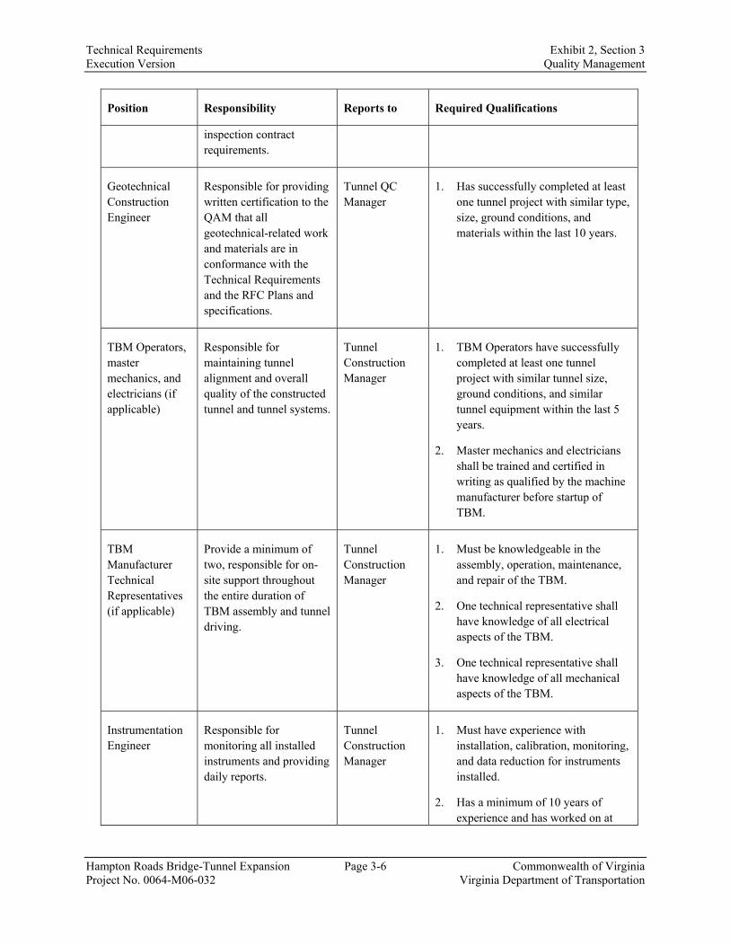
Technical Requirements Exhibit 2, Section 3 Execution Version Quality Management
Hampton Roads Bridge-Tunnel Expansion Page 3-6 Commonwealth of Virginia Project No. 0064-M06-032 Virginia Department of Transportation
Position Responsibility Reports to Required Qualifications
inspection contract requirements.
Geotechnical Construction Engineer
Responsible for providing written certification to the QAM that all geotechnical-related work and materials are in conformance with the Technical Requirements and the RFC Plans and specifications.
Tunnel QC Manager
1. Has successfully completed at least one tunnel project with similar type, size, ground conditions, and materials within the last 10 years.
TBM Operators, master mechanics, and electricians (if applicable)
Responsible for maintaining tunnel alignment and overall quality of the constructed tunnel and tunnel systems.
Tunnel Construction Manager
1. TBM Operators have successfully completed at least one tunnel project with similar tunnel size, ground conditions, and similar tunnel equipment within the last 5 years.
2. Master mechanics and electricians shall be trained and certified in writing as qualified by the machine manufacturer before startup of TBM.
TBM Manufacturer Technical Representatives (if applicable)
Provide a minimum of two, responsible for on-site support throughout the entire duration of TBM assembly and tunnel driving.
Tunnel Construction Manager
1. Must be knowledgeable in the assembly, operation, maintenance, and repair of the TBM.
2. One technical representative shall have knowledge of all electrical aspects of the TBM.
3. One technical representative shall have knowledge of all mechanical aspects of the TBM.
Instrumentation Engineer
Responsible for monitoring all installed instruments and providing daily reports.
Tunnel Construction Manager
1. Must have experience with installation, calibration, monitoring, and data reduction for instruments installed.
2. Has a minimum of 10 years of experience and has worked on at

Technical Requirements Exhibit 2, Section 3 Execution Version Quality Management
Hampton Roads Bridge-Tunnel Expansion Page 3-7 Commonwealth of Virginia Project No. 0064-M06-032 Virginia Department of Transportation
Position Responsibility Reports to Required Qualifications
least two projects with similar complexity?
Fabrication QA Manager
Implements the Fabrication QMP and manages verification inspection and testing of all off-site fabrication work.
Responsible for maintaining a fabrication NCR log and all fabrication calibration records for fabrication test equipment.
Tunnel Construction Manager
1. Must have at least 5 years of recent and relevant experience in fabrication inspection and fabrication QA, including qualification in welding, structural coatings, and precasting.
2. Cannot be employed by fabricators, material suppliers, or subsidiaries, and cannot have responsibility for construction production.
Fabrication QA Inspectors
Responsible to ensure that all of the QC inspections are completed according to the Fabrication QMP. Prepare Daily Fabrication Inspection Reports for the work performed and prepare Materials Receiving Reports to document inspection of materials during fabrication.
Fabrication QA Manager
1. Must have experience in fabrication inspection, with sufficient education and on-the-job training or trade school training to properly perform the test or inspection.
2. Cannot be employed by fabricators, material suppliers, or subsidiaries, and cannot have responsibility for construction production.
Fabrication QA and QC Testing Technicians
Perform the required QC and QA testing.
Tunnel QC Manager
1. Must have at least 5 years of recent and relevant experience in concrete fabrication QA and QC, including experience in concrete testing.
2. Tunnel design development, analysis, and drawings shall be performed by members of the lead design team that are independent of the tunnel design QC team (who have no involvement in the tunnel design). The same members of the lead design team shall complete all design QA reviews throughout the duration of the Project. The tunnel design QA and QC team members shall meet the requirements as set forth in the VDOT QA/QC Guide, Section 4.
3. The Tunnel Construction Manager is required to be at the location of the Project full-time during the tunnel fabrication/TBM assembly and for the entire duration of tunnel construction and is responsible for tunnel construction QC. The Tunnel Construction Manager shall have responsibility for managing the construction process, including all QC activities, to ensure the materials used and work performed meet contract requirements and the RFC Plans and specifications. The Tunnel Construction Manager shall be responsible for implementing,

Technical Requirements Exhibit 2, Section 3 Execution Version Quality Management
Hampton Roads Bridge-Tunnel Expansion Page 3-8 Commonwealth of Virginia Project No. 0064-M06-032 Virginia Department of Transportation
monitoring and, as necessary, adjusting the processes to assure acceptable quality of the construction work. The tunnel construction QA and QC team members shall meet the requirements as set forth in the VDOT QA/QC Guide, Section 5.
4. Tunnel QC personnel may not perform additional tasks on the Project beyond their QC functions during tunnel construction and TBM operation. As a minimum, provide the staff of QC personnel as follows:
a. During tunnel excavation, one full-time tunnel QC representative at the heading for each shift to inspect tunnel excavation and tunnel lining installation as it is occurring. Document inspection verification and acceptance on checklists, including any segment damage pre- or post-installation and repairs performed. The QA/QC Manager shall review the checklists on a daily basis.
b. During surface construction, one designated QC representative for each shift of surface construction work in addition to the tunnel QC representative for concurrent tunnel work. This inspection may be performed by the QA/QC Manager when authorized in writing by the Department. Multiple QC representatives may be required for each shift of surface work when concurrent work is occurring at multiple locations.
c. During concrete operations, one designated tunnel QC staff for each construction location and shift (when applicable) where concrete operations are conducted for inspection at the point of placement (e.g., invert cleaning, rebar placement, form release agent application, form alignment, invert drainage pipe installation, grout pipe placement, panning placement, water control, concrete placement, concrete sampling for testing, form stripping, concrete finishing and patching). Field Engineers and/or third-party inspectors may be used to assist with QC functions during large concrete placements or other critical portions of the Work.
d. During manufacturing of precast tunnel liner segments, one designated tunnel QC staff per day of segment production. A tunnel QC representative will be at the fabrication facility on a full-time basis from initial production start.
B. The Design-Builder will submit a Tunnel Quality Plan as part of its QA/QC Plan that will include:
1. Detail all required certifications and qualification documents, including a detailed plan of the site organization and responsibilities of all planned personnel, including, but not limited to, those shown above.
2. Fabrication Quality Management Plan: Provide detail of the tunnel lining fabricator’s QA/QC Plan. The Design-Builder’s approach to inspections and acceptance of all fabricated tunnel items shall include the following.
a. All items requiring fabrication inspection shall be inspected and accepted for conformance with RFC documents prior to being incorporated into the Project.
b. The Design-Builder or the fabricator shall reject any materials not conforming to the Contract Documents and the related RFC documents.
c. The Design-Builder shall submit the tunnel lining fabricator’s Quality Plan for the QC testing and inspection requirements for review and acceptance by the Department. The Lead Tunnel Engineer for the design of the tunnel shall review and approve this plan prior to submittal to the Department.

Technical Requirements Exhibit 2, Section 3 Execution Version Quality Management
Hampton Roads Bridge-Tunnel Expansion Page 3-9 Commonwealth of Virginia Project No. 0064-M06-032 Virginia Department of Transportation
d. No fabrication work activities that require QC, QA inspection, and testing shall commence until the Design-Builder’s QMP and its Tunnel Quality Plan, including the Fabrication QMP, has been accepted in writing by the Department.
e. The Fabrication QMP shall include an Inspection and Testing Plan describing all of the proposed QC inspections and tests to be performed throughout the fabrication process. The plan includes, but is not limited to:
i. Define fabricator’s QC responsibilities to include all activities performed by the fabricator, the producer, or the manufacturer to ensure that a product is of uniform quality meeting the Technical Requirements.
ii. Define the Design-Builder’s responsibilities, which include the quality of all fabricated items including materials and workmanship incorporated into the project. The Design-Builder shall monitor and measure the characteristics of all fabricated work activities to verify that all Project requirements have been met. This monitoring and measurement shall be carried out at appropriate stages of fabrication in accordance with the planned Work.
iii. Identify Hold Points when Work shall be accepted by QC personnel prior to proceeding to the next stage of the Work.
iv. Define the activity to be tested/inspected, the organization/laboratory to perform the test/inspection, the frequency of the test/inspection, the test/inspection procedure or reference standard, the specified requirement reference, and the record that documents the results.
v. Describe all of the material receiving, in-process, and final inspections and tests to be undertaken.
vi. Show what products or services are to be subcontracted. The Design-Builder is responsible for the QA/QC of all subconsultants. The Design-Builder shall perform regular audit of QA/QC procedures of subconsultants.
vii. Describe verification of compliance by suppliers and subcontractors with requirements.
viii. Identify who within the Construction QC organization has stop work authority.
3. Field Quality Control: Details of TBM data monitoring, including type of data, muck control and handling systems, ground movement monitoring, reporting and documentation, and ground treatment application.
4. Remedial Plan: Detailed method statements for remedial action, including:
a. Tunneling modifications if excessive lost ground occurs.
b. Corrective actions to be utilized for each Response Level associated with settlement and groundwater monitoring.
c. Plans for protection of adjacent facilities and property if excessive lost ground occurs or ground movements exceed Response Levels.
d. Plans for controlling groundwater inflows if TBM seals or tunnel lining leaks result in flow rates that exceed water tightness requirements specified in Technical Requirement 23 or cause detrimental lost ground.

Technical Requirements Exhibit 2, Section 3 Execution Version Quality Management
Hampton Roads Bridge-Tunnel Expansion Page 3-10 Commonwealth of Virginia Project No. 0064-M06-032 Virginia Department of Transportation
e. Plans for the repair of unacceptable segment off-sets, damage, or segment spalling.
5. Witness and Hold Points
a. As defined in the VDOT QA/QC Guide, Section 5.16, the Design-Builder shall establish Witness and Hold Points for the notification of the Department and Design-Builder’s tunnel design and construction personnel to observe or visually examine a specific work operation or tests.
i. The QAM shall designate the Tunnel QC Manager to be the primary point of contact for notifying the Department at Hold Points and Witness Points, and follow the process as outlined in the VDOT QA/QC Guide, Section 5.17, unless superseded by the Technical Requirements.
ii. The requirements for Hold Points and Witness Points for the construction of the tunnel structures, tunnel systems, and all other disciplines shall be comprehensive, and based on the VDOT QA/QC Guide, Sections 5.18 and 5.19.
iii. The requirements for Hold Points and Witness Points shall be specific to a bored tunnel, including its system and other requirements, and shall be subject to the Department’s review and approval.
iv. The Entrusted Engineer In Charge shall submit specific Hold Points with the RFC Plans. At a minimum, the Construction QAM shall establish Hold Points at the stages listed below. The QMP shall identify any additional Hold Points necessary to certify compliance. The Entrusted Engineer In Charge or Designer Manager (for specific features) shall be responsible for identifying in the submitted SPs those Hold Points they deem necessary to certify compliance. The following Hold Points are not intended to limit or diminish the Design-Builder’s responsibility to inspect all construction Work:
1) Construction Monitoring
a) After installation and completion of initialization readings for instruments.
b) After reaching “Maximum Level” readings on construction monitoring instrumentation, until construction procedures and mitigation measures have been resolved.
2) Existing Structures and Utilities Settlement Mitigation (if deemed necessary)
a) After implementation of any settlement mitigation procedure for the existing immersed tube tunnel or any structure and/or utilities along the alignment.
3) In the fabrication process where critical characteristics are to be measured and maintained, and at points where it is impractical to determine the adequacy of either materials or workmanship once work proceeds past this point.
4) Tunnel Boring Machine Startup
a) At completion of TBM assembly and testing, prior to commencement of tunneling.
5) Tunnel, Interior Roadway, Support of Excavation and Cut and Cover Walls
a) After tunnel excavation completion and prior to placement of any components of the interior structure.

Technical Requirements Exhibit 2, Section 3 Execution Version Quality Management
Hampton Roads Bridge-Tunnel Expansion Page 3-11 Commonwealth of Virginia Project No. 0064-M06-032 Virginia Department of Transportation
b) After verification that the tunnel liner achieved desired infiltration criteria and prior to installation of any tunnel finishes components.
c) At completion of excavation and before the start of structure foundation.
d) Before saw-cutting of concrete.
e) Before concrete placement of roadway deck, diaphragms, traffic barrier, and interior tunnel walls (with formwork, inserts, and reinforcement in place).
f) After completion of excavation and prior to cut-and-cover construction.
g) Before concrete placement for cast-in-place tunnel sections with formwork, inserts, and reinforcement in place.
6) Electrical and Tunnel Systems
a) Prior to start of installation of tunnel systems in the tunnel.
b) Prior to start of equipment installation in the tunnel support buildings.
C. Performance Verification of Project Geotechnical Elements/Features
1. Given the complexity and sensitivity of the marine and geotechnical elements and features of a tunnel project, this section supplements verification requirements as detailed in the VDOT QA/QC Guide, Section 5.20.
2. The geotechnical engineer of record, as defined in the VDOT QA/QC Guide, Section 5.20.1, shall:
a. Verify the qualifications of geotechnical QA and QC personnel listed in Technical Requirement 15, Section 15.3.1, and certify that the QA and QC was performed by personnel qualified by education, experience, and training to conduct the quality activities outlined in the Design-Builder’s QA/QC Plan and as required in Technical Requirement 15.
b. The Design-Builder shall submit a complete QA/QC Plan for project geotechnical elements/features, including but not limited to:
i. Expansion of the existing islands.
ii. Creation of engineered fill berms to enable bored tunnel construction.
iii. Excavation of subaqueous trenches.
iv. Foundations for structures and appurtenances, including but not limited to the following: tunnels, tunnel approach structures, ventilation buildings and other tunnel ancillary facilities, and other traffic control devices.
v. Ground improvement work associated with tunnel construction and/or tunnel approach structures construction.
3.2. Department’s Oversight Role A. The Department’s oversight activities include:
1. Meeting with the Design-Builder.
2. Reviewing progress reports and payment requests.

Technical Requirements Exhibit 2, Section 3 Execution Version Quality Management
Hampton Roads Bridge-Tunnel Expansion Page 3-12 Commonwealth of Virginia Project No. 0064-M06-032 Virginia Department of Transportation
3. Verifying progress.
4. Auditing payroll records.
5. Partnering.
6. Auditing the subcontracting process.
7. Verifying DBE, EEO, and other affirmative action compliance.
8. Conducting management reviews.
9. Participating in progress meetings.
10. Reviewing Baseline Schedule and updates.
11. Reviewing management-related plans.
12. Reviewing compliance and control.
13. Independent Assurance/Independent Verification activities.
14. Providing approvals, authorizations, acceptance and consent.
15. Reviewing Design-Builder’s design.
16. Performing audits of the implementation by the Design-Builder of the Design-Builder’s Quality Plan, including Independent Assurance and list of Hold Points and Witness Points, verification sampling and testing, and inspection.
17. Performing audits of the fabricator’s QC performance, including testing frequencies and acceptance testing results. The Department shall be provided access to conduct oversight inspections to verify the adequacy of the fabricator’s inspection activities, testing procedures, storing of inventory, and transport/shipping quality processes.
3.2.1. Department Approvals
A. The Department will approve only those submittals, activities, actions, or work that are specifically identified as being for approval in Part 4, Article 3.1. Any approvals by the Department will be provided to the Design-Builder in writing only.
B. The Department’s approvals identified in the Agreement are summarized below. Nothing in this subsection limits any other approvals that may be required pursuant to or in connection with the requirements of the Agreement and the Technical Requirements:
1. Agreement Periodic Payment Schedule (Part 4, Article 6.1).
2. Requests for periodic payments (Part 4, Article 6.2).
3. Requests for payment for materials delivered to the Project (Part 4, Article 6.2.2).
4. Changes to Agreement Price (by Work Order only) (Part 4, Article 9.5).
5. Revised Schedule of Prices (Part 4, Article 9.5).
6. Revised Contract Periodic Payment Schedule (Part 4, Article 6.1).

Technical Requirements Exhibit 2, Section 3 Execution Version Quality Management
Hampton Roads Bridge-Tunnel Expansion Page 3-13 Commonwealth of Virginia Project No. 0064-M06-032 Virginia Department of Transportation
7. Baseline Schedule and updates (Technical Requirement 2, Section 2.3.2).
8. Project specifications representing lower quality than that specified in the Contract, including the Design-Builder’s Proposal (Part 3, Article 3.5).
9. Deviations from sampling and testing methods or frequencies.
10. Limited Access Control Change.
11. All Work Orders including No Cost/No Time deviations and changes.
C. The Department’s review, oversight, audit, and inspection activities are referred to as “consultation and written comment” (Part 5, Section 103.08). The Department’s consultation and written comment will be confirmed to the Design-Builder in writing only, by the Department only. The Design-Builder shall be responsible for addressing the Department’s comments.
D. The Department will provide consultation and written comment, approvals, and Non-Conformance Reports pursuant to Part 4, Article 6.2.1.2.
E. The Design-Builder shall indicate in writing whether it agrees with the Department’s comments. If the Design-Builder does not agree with the Department’s comments, then the Department and Design-Builder shall work together to resolve the issue before proceeding with design.
F. If agreement cannot be reached, the issue will be resolved as provided in the Contract Documents for dispute resolution in accordance with Part 4, Article 10.2.
G. For any plan submittal requesting release for construction, upon satisfaction of all requirements, the Department shall provide authorization to commence construction in accordance with the plans.
H. For interim plan submittals and other submittals not requiring approval or authorization, upon satisfaction of all requirements the Department shall accept the submittal as final or consent to it use.
3.2.2. Department’s Oversight Role during Design
A. The Department’s oversight role during design and design review consists of monitoring and auditing design progress, including for payment, interpreting Agreement requirements, and verifying design compliance with Agreement requirements.
B. The Department’s oversight roles and activities relating to design will include, but are not limited to, the following:
1. Assisting in providing interpretation and answers regarding Agreement requirements on a regular basis, often daily (such involvement is often termed over-the-shoulder review). Any interpretation would be based on the information available or provided at the time and should not be considered an approval, authorization, or acceptance until it is formalized and documented in writing as part of a complete submittal that is agreed to in writing.
2. Providing input and participation in the review process as agreed to during the design workshop.
3. Participating in design reviews, excluding detailed checks of plans and calculations except in cases where it is deemed in the best interest of the Department. The Department’s review

Technical Requirements Exhibit 2, Section 3 Execution Version Quality Management
Hampton Roads Bridge-Tunnel Expansion Page 3-14 Commonwealth of Virginia Project No. 0064-M06-032 Virginia Department of Transportation
may not include all aspects or areas of the submittal. Comments that are provided are not intended to have captured all deficiencies.
4. Verifying through monitoring and auditing of QC and QA records, including check prints of analyses and drawings, that the Design-Builder’s Design Quality Manager is fulfilling his/her responsibilities and that the quality systems contained in the QA/QC Plan are being followed. An audit may include detailed checks of plans and calculations and review of the Design-Builder’s QA and QC records.
3.2.3. Department’s Oversight Role during Construction
A. The Department’s oversight role during construction consists of monitoring and auditing construction progress including for payment, interpreting Agreement requirements, and verifying construction compliance with Agreement requirements.
B. The Department’s oversight roles and activities relating to construction will include, but are not limited to, the following:
1. Independent Assurance/Independent Verification.
2. Verification sampling and testing.
3. Auditing and monitoring of QC and QA to verify that the Design-Builder’s Quality Manager is fulfilling his/her responsibilities and that the quality system contained in the CQMP is being followed.
4. Auditing safety and security records and checking the qualifications of safety and security personnel.
5. Reviewing and spot-checking Design-Builder’s work zone traffic control activities and installations.
6. Conducting reviews of As-Built Drawings.
7. Assuming responsibility for coordinating with appropriate state or federal agencies upon encountering previously unknown, unidentified hazardous materials.
3.3. Deliverables At a minimum, the deliverables shall include the items listed in Table 3.3-1 for the Department’s review and consideration.
Table 3.3-1 Deliverables
Deliverable Number of Copies
Delivery Schedule1 Reference
Section Hard Copy Electronic
QA/QC Plan also known as Quality Management System Plan (QMSP)
5 1 3.1
Design QA/QC Plan (DQMP) 5 1 3.1.1

Technical Requirements Exhibit 2, Section 3 Execution Version Quality Management
Hampton Roads Bridge-Tunnel Expansion Page 3-15 Commonwealth of Virginia Project No. 0064-M06-032 Virginia Department of Transportation
Deliverable Number of Copies
Delivery Schedule1 Reference
Section Hard Copy Electronic
Construction QA/QC Plan (CQMP)
5 1 15 days before start of investigation work
3.1.2
Quality AR Plan 5 1
60 days after completion of investigation, including testing
3.1.2.B
Tunnel Quality Plan (Design) 5 1 3.1.3
Tunnel Quality Plan (Construction)
5 1
60 days prior to tunneling activities, including tunnel liner fabrication. This does not apply to the TBM manufacturer’s quality plan.
3.1.3
Note 1: Each stated deliverable is to be submitted on the schedule/date as stated in the Technical Requirements. If no submittal schedule/date is provided in the Technical Requirements, the Design-Builder shall provide a submitted date for that deliverable in the Preliminary Schedule, to be approved by the Department and incorporated in the Baseline Schedule.

Technical Requirements Exhibit 2, Section 4 Execution Version Standards
Hampton Roads Bridge-Tunnel Expansion Page 4-1 Commonwealth of Virginia Project No. 0064-M06-032 Virginia Department of Transportation
SECTION 4. STANDARDS
4.1. General Requirements A. The Design-Builder shall use the version of Standards in force on the Setting Date.
B. It is the Design-Builder’s responsibility to obtain clarification of any apparent error, omission, ambiguity, or conflict regarding any Standard; the Department, at its sole discretion, will determine the applicable clarification.
C. For Work not specifically covered by the individual sections of the Technical Requirements, the Design-Builder shall, at a minimum, apply the Standards normally applied by the Department for such Work, to the extent they do not conflict with requirements in the Agreement. The Design-Builder shall be solely responsible for ensuring that it identifies and applies all correct Standards.
D. Access to and document ordering information for most VDOT Standards are available from the following website: http://www.virginiadot.org/business/manuals-default.asp
E. Access to all revisions to the VDOT 2016 Road and Bridge Specifications SPs Separated by Specification Division may be found at: http://www.virginiadot.org/business/const/spec-default.asp
F. These website addresses have been supplied to the Design-Builder for convenience only, to help the Design-Builder locate the required Standard and are not guaranteed to be correct. It is the Design-Builder’s responsibility to locate the required Standard and to determine if the Standard has been modified pursuant to the Agreement.
G. The summary lists and groupings of standards, specifications, special provisions, and other reference documents in this Technical Requirement are solely for the Design-Builder’s convenience. This information does not supplement or supersede the list of documents specified within each of the other Technical Requirements.
4.2. Specific Requirements A. The Work for the Project shall be performed in accordance with the applicable federal and state
laws and VDOT Standards, Specifications, and reference documents to include, but not limited to, the documents listed herein. The Design-Builder shall verify and use the latest versions of the documents listed herein as of the Setting Date. The Design-Builder shall meet or exceed the minimum roadway design standards and criteria except for the design exceptions and waivers provided in Technical Requirement 17, Appendix A17-2.
B. If during the design, the Design-Builder determines that a specific Standard, Specification, or reference document is required but is not listed herein, it is the responsibility of the Design-Builder to identify the pertinent Standard, Specification, or reference document and submit it to the Department for review and approval prior to inclusion in the Agreement documents.
C. The VDOT 2016 Road and Bridge Specifications, and its SPCN, contain pricing language under sections entitled “Measurement and Payment” that is not applicable in the Design-Build context of this Contract. Thus, in accordance with the hierarchy of documents, the Design-Builder shall refer to Part 3, Articles 6 and 7; Part 4, Article 6; and applicable portions of Part 5 to the Standard Specifications for more information regarding the pricing and payment to the Design-Builder. Similarly, any other references to pricing methodologies for the “Contractor” shall likewise be superseded. The requirements as described in the Technical Requirements take precedence over the referenced documents listed below, unless otherwise indicated.

Technical Requirements Exhibit 2, Section 4 Execution Version Standards
Hampton Roads Bridge-Tunnel Expansion Page 4-2 Commonwealth of Virginia Project No. 0064-M06-032 Virginia Department of Transportation
1. The Design-Builder shall assume that all provisions of the Standards, including the figures and tables, are mandatory, and guidelines contained therein shall be assumed to be requirements.
2. When a Standard refers to an action being necessary, needed, or recommended, the Design-Builder shall interpret the action as required unless the context requires otherwise, as determined at the sole discretion of the Department.
3. Except with respect to any Work for which the Design-Builder is to be paid on a unit price or force account basis, any references in the Standards related to payment, Pay Items or quantities, measurement for payment, method of measurement, basis of payment, Extra Work, adjustment of unit prices, or similar phrases shall be disregarded by the Design-Builder, since the Agreement Price is full compensation for the Work.
4. Where reference is made in the Standards to items that are indicated or required in the plans or SPs, the plans or SP shall mean the Design-Builder’s plans or SP.
5. References in the Standards to approved products or materials shall mean approved by the Department.
6. All references in the Standards to the Inspector, field inspector, Project Engineer, Engineer, Materials Engineer, District Materials Engineer, survey crew, Project supervisor, agency-certified technician, certified plant technician, and Representative of the Office of Materials shall mean the Design-Builder, except as otherwise expressly provided in the Agreement or otherwise directed by the Department.
7. When a Standard uses the term “Engineer” relating to activation or de-activation of railroad or highway signals, or the approval of any activities involving the use of explosives, such term shall mean the Department.
8. When approval or authorization by the “Engineer” is required in a Standard for the use of alternative or substituted processes or components, this shall mean the Department.
9. When a Standard requires actions, dimensions, spacing, design information, materials as designed, means, or methods that are “either as indicated in the plans or as designated by the Engineer,” the Design-Builder shall disregard the phrase “or as designated by the Engineer.”
10. When a Standard refers to the “Engineer” ordering work beyond the scope of work in the Agreement, “Engineer” shall mean the Department.
11. Wherever references to “Engineer” result in testing or acceptance procedures being assigned to the Engineer, acceptance shall be on behalf of the Department. The Department reserves the right to perform additional tests and inspections as necessary to confirm that the Work is in conformance with Agreement requirements and will be the only party authorized to accept or authorize the Work on behalf of the Department.
12. When a Standard refers to unauthorized Work or to acceptance of Non-Conforming Work by the “Engineer,” the “Engineer” shall mean the Department.
13. When any references occur in a Standard to the “Engineer” that refer to the time period after Final Completion, the term “Engineer” shall mean the Department.
14. When a Standard requires notifications to the “Engineer,” the “Engineer” shall mean the Department.
15. When a Standard refers to an approval of any correction or repair that deviates from the Agreement requirements, the approval will be by the Department.

Technical Requirements Exhibit 2, Section 4 Execution Version Standards
Hampton Roads Bridge-Tunnel Expansion Page 4-3 Commonwealth of Virginia Project No. 0064-M06-032 Virginia Department of Transportation
16. When a Standard refers to items that will be performed or provided by the Department or by a division or employee of the Department, the Design-Builder shall understand the requirements as applying to the Design-Builder unless otherwise specified in the Agreement documents or unless the context requires otherwise. It shall be at the Department’s sole discretion to determine when the context requires otherwise.
17. When a Standard refers to the “Project Manager” as it relates to plan processes, sending information, or requesting information from the Department entities, the term “Project Manager” shall mean the Department. The Design-Builder shall submit all requests directly to the Department.
18. The Design-Builder shall perform Work relevant to each Technical Requirement in accordance with the Standard(s), if any, that are listed in that Technical Requirement, unless otherwise stipulated in that Technical Requirement.
19. The Design-Builder shall follow all standards, laws, and rules necessary to perform the Work, regardless of whether an applicable standard, regulation, law, or rule is specified in the Technical Requirements.
4.3. Standards and Specifications A. The standards and references for the Project are listed below in the following order:
1. Standards and Specifications.
2. Additional reference documents.
3. SP List including SPs, SPCN, and Supplemental Specifications.
B. Items 1 and 2 are published references that are available publicly, for which copies are not provided to the Design-Builder but which are to be used as manuals for design and construction. Documents listed in Item 3 are included in the Disclosed Information.
Standards and Specifications
General
1. AASHTO Guide Specifications for Highway Construction, 9th Edition.
2. VDOT Materials Approved Lists.
3. VDOT Construction Manual (2005, Revised May 2016).
4. VDOT Post Construction Manual (December 2016).
5. VDOT Construction Inspection Manual (January 2017).
6. VDOT Minimum Requirements for QA/QC on Design Build & Public-Private Transportation Act Projects (July 2018).
7. VDOT Traffic Engineering Design Manual (September 2014).
8. VDOT TOSAM – Version 1.0 (November 2015).
9. VDOT Right of Way Manual of Instruction, Third Edition (January 1, 2016, Revised October 13, 2017).
10. VDOT Utility Manual of Instruction– Utility Relocation Policies and Procedures, Eleventh Edition (October 1, 2016, Revised August 14, 2017).

Technical Requirements Exhibit 2, Section 4 Execution Version Standards
Hampton Roads Bridge-Tunnel Expansion Page 4-4 Commonwealth of Virginia Project No. 0064-M06-032 Virginia Department of Transportation
11. VDOT Land Use Permit Regulations Guidance Manual (March 17, 2010, Revised May 20, 2013).
12. VDOT Land Use Permit Regulations 24 VAC 30-151 (March 17, 2010).
13. VDOT Public Involvement Manual, Policy Manual for Public Participation in Transportation Projects (Revised November 2016).
14. VDOT Instructional & IM – All Divisions.
15. VDOT Road and Bridge Standards, Vol. 1 and Vol. 2 (2016).
16. VDOT Road and Bridge Specifications (2016) including Supplements, SPCNs, SPs, and SSs.
17. VDOT Statewide Maintenance Practices Manual.
18. VDOT Virginia Work Area Protection Manual (2011 Edition, Revision 1 April 1, 2015).
19. U.S. Department of Justice ADA Standards for Accessible Design (September 15, 2010).
20. U.S. Access Board Proposed Accessibility Guidelines for Pedestrian Facilities in the Public Right-of-Way (July 26, 2011).
21. U.S. Access Board ADA and Architectural Barriers Act (ABA) Accessibility Guidelines for Buildings and Facilities (July 23, 2004, Revised May 7, 2014).
22. VDOT Policy for Integrating Bicycle and Pedestrian Accommodations (March 18, 2004 by the CTB).
23. Transportation Research Board Highway Capacity Manual, 6th Edition (2016).
24. VDOT CADD Manual (Issued 2012, Revised February 2018).
25. VDOT State Noise Abatement Policy (July 13, 2011).
26. ISO 9001:2015 Quality Management Systems (September 2015).
27. AASHTO Guide for Park-and-Ride Facilities, 2nd Edition (2004).
28. Virginia Uniform Statewide Building Code (2012, effective July 14, 2014).
29. Uniform Relocation Assistance and Real Property Acquisition Act (URA) of 1970, as amended.
30. Code of Virginia, Titles 25.1 and 33.2, as amended.
31. DGS BCOM CPSM.
32. Commonwealth of Virginia Energy Conservation Code.
33. ASCE 37 Design Loads on Structures during Construction.
34. fib Model Code for Service Life Design.
35. OSHA Regulations.
Environmental
1. VDOT Asbestos Project Monitoring and Clearance Air Monitoring Procedures.
2. VDOT Asbestos Inspection Procedures.

Technical Requirements Exhibit 2, Section 4 Execution Version Standards
Hampton Roads Bridge-Tunnel Expansion Page 4-5 Commonwealth of Virginia Project No. 0064-M06-032 Virginia Department of Transportation
Roadway Design
1. VDOT State Bicycling Policy Plan (September 2011).
2. VDOT State Pedestrian Policy Plan (September 2014).
3. VDOT 2014 Functional Classification Maps.
4. VDOT Road Design Manual (Issued January 2005, Revised July 2018).
5. VDOT Allowable Lane Closure Hours for the State Highway System in Hampton Roads District (August 2018).
6. AASHTO A Policy on Geometric Design of Highways and Streets, 6th Edition (2011).
7. AASHTO Roadside Design Guide, Fourth Edition (October 2011, updated Chapter 6).
8. AASHTO A Policy on Design Standards - Interstate System, 5th Edition (January 2005).
9. AASHTO Guide for HOV Facilities, 3rd Edition (2004).
10. AASHTO Guide for the Development of Bicycle Facilities, 4th Edition (2012).
11. AASHTO Guide for the Planning, Design, and Operation of Pedestrian Facilities, 1st Edition (July 2004).
12. FHWA 23CFR630 Subpart J Work Zone Safety and Mobility (September 2005).
13. FHWA Guide to HOT Lane Development (2003).
14. FHWA Price Managed Lane Guide (October 2012).
15. FHWA Use of Freeway Shoulders for Travel—Guide for Planning, Evaluating, and Designing Part-Time Shoulder Use as a Traffic Management Strategy (February 2016).
Geotechnical and Pavement Design
1. AASHTO Guide for Design of Pavement Structures, 4th Edition with 1998 Supplement Rigid Pavement and Flexible Pavement (1993 Edition and subsequent Revisions).
2. AASHTO Manual on Subsurface Investigations, 1st Edition (1988).
3. VDOT Materials Division, Pavement Design and Evaluation Section, Guidelines for AASHTO Pavement Design.
4. VDOT Pavement Design Guide for Subdivision and Secondary Roads in Virginia (Revised February 2014).
5. VDOT Manual of Instruction for Materials Division (January 2018).
6. VDOT MOI for Materials Division, Chapter VI Pavement Evaluation and Design.
7. VDOT Manual of the Structure and Bridge Division, Part 11 – Geotechnical Manual for Structures (February 3, 2017).
8. FHWA 23CFR626 Pavement Policy (January 1, 2011).
9. K. H. McGee Pavement Consultant: Development and Implementation of Pavement Condition Indices for the VDOT: Phase I – Flexible Pavements (January 30, 2003).
10. AASHTOWare Pavement ME, Version 2.2.6 and VDOT AASHTOWare Pavement ME User Manual (September 2017).

Technical Requirements Exhibit 2, Section 4 Execution Version Standards
Hampton Roads Bridge-Tunnel Expansion Page 4-6 Commonwealth of Virginia Project No. 0064-M06-032 Virginia Department of Transportation
11. ASTM Standards, Soil and Rock, Volumes 04.08 and 04.09.
12. ASTM Standards, Concrete and Aggregates, Volume 04.02.
13. USACE Laboratory Soils Testing, EM-1110-2-1906.
14. USACE Hydraulic Design Criteria Sheet 712-1 Stone Stability.
15. USACE Construction with Large Stone, EM 1110-2-2302.
16. VTRC 06-CR12 Design of Bridging Layers in Geosynthetic-Reinforced, Column-Supported Embankments.
Structures
1. VDOT Manual of the Structure and Bridge Division.
2. VDOT Supplement to the AASHTO Manual for Bridge Element Inspection (January 2016).
3. AASHTO Guide Specification for LRFD Seismic Bridge Design, 2nd Edition (2011, Interim Revisions 2012, 2014, and 2015).
4. AASHTO LRFD Bridge Design Specification, 7th Edition (2014) and VDOT Modifications (IIM-S&B-80, August 25, 2015).
5. AASHTO Standard Specifications for the Design of Highway Bridges, 16th Edition (1996, with 1997 and 1998 Interim Specifications) and VDOT Modifications.
6. AASHTO Guide Specifications for Structural Design of Sound Barriers, current edition and interims.
7. AASHTO Guide Specifications Thermal Effects in Concrete Bridge Superstructure, 1st Edition.
8. AASHTO Guide Specification and Commentary for Vessel Collision Design of Highway Bridges.
9. AASHTO Guide Specification for Design of Bonded FRP Systems for Repair and Strengthening of Concrete Bridge Elements, 1st Edition (2012).
10. AASHTO Guide Specifications for Wind Loads on Bridges During Construction (2017).
11. AASHTO Construction Handbook for Bridge Temporary Works, 2nd Edition (2017).
12. AASHTO Guide Design Specifications for Bridge Temporary Works, 2nd Edition (2017).
13. AASHTO Manual for Bridge Evaluation, 2nd Edition (2011, 2013, 2014, 2015, and 2016 Interim Revisions).
14. AASHTO Standard Specifications for Structural Supports for Highway Signs, Luminaries, and Traffic Signals, 6th Edition, (2013, Interim Revisions 2015).
15. FHWA Guidelines for the Installation, Inspection, Maintenance and Repair of Structural Supports for Highway Signs, Luminaires, and Traffic Signals (March 2005), FHWA NHI 05-036.
16. FHWA Recording and Coding Guide for the Structure Inventory and Appraisal of the Nation’s Bridges (December 1995, including Errata sheets and Revisions).
17. FHWA 23CFR625 Design Standards for Highways (October 14, 1997, including Errata sheets and Revisions).

Technical Requirements Exhibit 2, Section 4 Execution Version Standards
Hampton Roads Bridge-Tunnel Expansion Page 4-7 Commonwealth of Virginia Project No. 0064-M06-032 Virginia Department of Transportation
18. FHWA 23CFR630 Subpart B – Plans, Specifications, and Estimates (December 9, 1991).
19. FHWA 23CFR650 Subpart C –NBIS (December 7, 1994), Subsection 650.301 or the latest Revision(s).
20. FHWA-HIF-18-002 A Primer on Modeling in the Coastal Environment (2017).
21. FHWA-HIF-17-032 Bridge Security Design Manual (2017).
22. AASHTO LRFD Bridge Construction Specifications, 4th Edition (2017).
23. AASHTO Guide Specifications for Seismic Isolation Design, 4th Edition (2014).
24. AASHTO Manual for Bridge Element Inspection, 1st Edition (2013, with 2015 Interim Revisions).
25. AASHTO Guide Specifications for Bridges Vulnerable to Coastal Storms (2008).
26. AASHTO Security Transportation Task Force Recommendations for Bridge and Tunnel Security (2003).
27. AASHTO/NSBA Steel Bridge Collaboration Shop Detail Drawing Presentation Guidelines, G1.3 – 2002.
28. AASHTO/NSBA Steel Bridge Fabrication Guide Specifications, S2.1-2016.
29. ANSI/AWS D1.2/D1.2M Structural Welding Code – Aluminum, current edition.
30. ANSI/AWS D1.1/D1.1M Structural Welding Code – Steel, current edition.
31. ANSI/AWS D1.5M/D1.5 2015-AMD1 Bridge Welding Code, 6th Edition (2015).
32. ANSI/AWS D1.6M/D1.6 Structural Welding Code – Stainless Steel.
33. AISC Steel Construction Manual, 14th Edition.
34. AISC Design Guide 27 Structural Stainless Steel.
35. NCHRP Report 350 Recommended Procedures for the Safety Performance Evaluation of Highway Features.
36. AASHTO Manual for Assessing Safety Hardware, 1st Edition.
37. AASHTO/FHWA Joint Implementation Plan for the AASHTO MASH (2009).
38. NFPA 14 Standard for the Installation of Standpipe and Hose Systems (2013).
39. NFPA 25 Standard for the Inspection, Testing, and Maintenance of Water-Based Fire Protection Systems (2014).
40. NFPA 70 NEC (2011).
41. NESC Standards.
42. NFPA 502 Standard for Road Tunnels, Bridges, and other Limited Access Highways (2017).
43. VDOT Element Data Collection Manual (2007).
44. VDOT Memorandum – Asbestos Containing Materials on Bridges (October 23, 2009).
45. VDOT Asbestos Inspection Procedures (May 4, 2004).
46. VDOT Guide Manual for Causes and Repair of Cracks in Bridge Decks (September 25, 2009).

Technical Requirements Exhibit 2, Section 4 Execution Version Standards
Hampton Roads Bridge-Tunnel Expansion Page 4-8 Commonwealth of Virginia Project No. 0064-M06-032 Virginia Department of Transportation
47. ADA Standards for Accessible Design.
48. SSPC Standards.
49. VA Statewide Fire Prevention Code.
50. USACE Strength Design for Reinforced Concrete Hydraulic Structures, EM 1110-2-2100.
51. USACE Retaining and Flood Walls, EM 1110-2-2502.
52. ACI 318-14 Building Code Requirements for Structural Concrete and Commentary.
53. ASCE 37-02 Design Loads on Structures during Construction.
54. Virginia Work Area Protection Manual.
55. Virginia Construction Code.
56. Virginia USBC.
Tunnel Approach Structures:
1. VDOT Manual of Structure and Bridge Division.
2. VDOT Road and Bridge Standards, Vol. 1 and Vol. 2.
3. VDOT Instructional and Informational Memorandum.
4. AASHTO LRFD Road Tunnel Design and Construction Guide Specifications.
5. AASHTO Technical Manual for Design and Construction of Road Tunnels- Civil Elements.
6. AASHTO LRFD Bridge Design Specification, 7th Edition (2014) and VDOT Modifications (IIM-S&B-80).
7. AASHTO Guide Design Specifications for Bridge Temporary Works, 2nd Ed., 2017.
8. AASHTO LRFD Bridge Construction Specifications, 4th Ed.
9. AASHTO Guide Specifications for Wind Loads on Bridges during Construction, 2017.
10. AASHTO MASH.
11. NFPA 502 – Standards for Road Tunnels, Bridges, and Other Limited Access Highways.
12. AWS D1.1M/D1.1 Structural Welding Code – Steel.
13. AWS D1.6M/D1.6 Structural Welding Code – Stainless Steel.
14. VDOT SPCN for Stainless Steel Strand for Design Build and PPTA Contracts.
15. VDOT SP for Hydraulic Cement Concrete Operations for Massive Construction.
16. VDOT SP for Carbon Fiber Reinforced Prestressed Concrete Piles for Design-Build and PPTA Contracts.
17. VDOT SP for Drilled Shafts Using Self-Consolidating Concrete for Design- Build and PPTA Contracts.
18. VDOT SP for Micropiles for Design Build and PPTA Projects.
19. AISC Steel Construction Manual 14th Edition.
20. AISC Design Guide 27: Structural Stainless Steel.
21. FHWA TOMIE Manual.

Technical Requirements Exhibit 2, Section 4 Execution Version Standards
Hampton Roads Bridge-Tunnel Expansion Page 4-9 Commonwealth of Virginia Project No. 0064-M06-032 Virginia Department of Transportation
22. 23CFR650 Subpart E –NTIS.
23. ACI 318-14 Building Code Requirements for Structural Concrete and Commentary.
24. ASCE 37-02 Design Loads on Structures during Construction.
25. fib Model Code for Service Life Design.
26. Commonwealth of Virginia Work Area Protection Manual.
27. Commonwealth of Virginia Construction Code.
28. Commonwealth of Virginia USBC.
29. American Society of Mechanical Engineers ASME B30.10 – Hooks, plus Addenda.
30. American Society of Mechanical Engineers ASME B30.16 – Overhead Hoists (Underhung) plus Addenda.
31. American Society of Mechanical Engineers ASME HST-4M – Performance Standard for Overhead Electric Wire Rope Hoists.
32. CMAA – No. 70 – Specifications for top running bridge and gantry-type multiple girder electric overhead traveling cranes.
Bored Tunnel
1. VDOT Manual of Structure and Bridge Division.
2. VDOT Road and Bridge Specifications, including all revisions (excluding Section 103).
3. VDOT Road and Bridge Standards, Vol. 1 and Vol. 2 (2016).
4. VDOT IIM – All Divisions.
5. VDOT Supplement to the AASHTO Manual for Bridge Element Inspection (January 2016).
6. AASHTO LRFD Road Tunnel Design and Construction Guide Specifications, First Edition, 2017.
7. AASHTO LRFD Bridge Design Specification, 7th Edition (2014) and VDOT Modifications (IIM-S&B-80)
8. AASHTO Technical Manual for Design and Construction of Road Tunnels- Civil Elements.
9. AASHTO Guide Specifications for Wind Loads on Bridges During Construction, 2017.
10. AASHTO Construction Handbook for Bridge Temporary Works, 2nd Edition (2017).
11. AASHTO Guide Design Specifications for Bridge Temporary Works, 2nd Edition (2017).
12. AASHTO Manual for Bridge Evaluation, 2nd Edition, 2011, 2013, 2014, 2015, and 2016 Interim Revisions.
13. NFPA 502 – Standards for Road Tunnels, Bridges and Other Limited Access Highways
14. AWS D1.1M/D1.1 Structural Welding Code – Steel.
15. AWS D1.6M/D1.6 Structural Welding Code – Stainless Steel.
16. AISC Steel Construction Manual 14th Edition.
17. AISC Design Guide 27: Structural Stainless Steel.
18. FHWA TOMIE Manual.

Technical Requirements Exhibit 2, Section 4 Execution Version Standards
Hampton Roads Bridge-Tunnel Expansion Page 4-10 Commonwealth of Virginia Project No. 0064-M06-032 Virginia Department of Transportation
19. 23CFR650 Subpart E –NTIS.
20. FHWA NH1-10-034, Technical Manual for the Design and Construction of Road Tunnels –
21. FHWA-HIF-15-006, Specifications for National Tunnel Inventory.
22. Best Practices for Implementing QC/QA for Tunnel Inspection prepared for AASHTO T-20.
23. ACI 544.7R-16 Report on Design and Construction of Fiber-Reinforced Precast Concrete Tunnel Segments.
24. ACI SP-310 Fiber Reinforced Concrete: From Design to Structural Applications FRC 2014: ACI-fib International Workshop.
25. ACI 318-14 Building Code Requirements for Structural Concrete and Commentary.
26. ASCE 37-02 Design Loads on Structures during Construction.
27. fib Model Code for Service Life Design.
28. Commonwealth of Virginia Work Area Protection Manual.
29. Commonwealth of Virginia Construction Code.
30. Commonwealth of Virginia USBC.
Drainage
1. VDOT 2002 Drainage Manual (including current Errata Sheets) and Revisions (Revised July 2017).
2. Virginia Stormwater Management Handbook, Volume I & Volume II, First Edition (1999), Virginia Department of Conservation and Recreation.
3. 2013 Virginia Stormwater Management Handbook, Second Edition.
4. DEQ 2013 BMP Standards and Specifications.
5. Virginia Erosion and Sediment Control Handbook, Third Edition (1992), Department of Conservation and Recreation.
6. FHWA Hydraulic Design Series Number 5 (HDS-5), Hydraulic Design of Highway Culverts, Third Edition.
7. FHWA Hydraulic Design Series Number 6 (HDS-6), River Engineering for Highway Encroachments (2001).
8. FHWA Hydraulic Engineering Circular Number 9 (HEC-9), Debris Control Structures Evaluation and Countermeasures (2005).
9. FHWA Hydraulic Engineering Circular Number 15 (HEC-15), Design of Roadside Channels with Flexible Linings, Third Edition (2005).
10. FHWA Hydraulic Engineering Circular Number 14 (HEC-14), Hydraulic Design of Energy Dissipaters for Culverts and Channels (2006).
11. FHWA Hydraulic Engineering Circular Number 17 (HEC-17), The Design of Encroachments on Floodplains Using Risk Analysis (1981).
12. FHWA Hydraulic Engineering Circular Number 18 (HEC-18), Evaluating Scour at Bridges (2012).

Technical Requirements Exhibit 2, Section 4 Execution Version Standards
Hampton Roads Bridge-Tunnel Expansion Page 4-11 Commonwealth of Virginia Project No. 0064-M06-032 Virginia Department of Transportation
13. FHWA Hydraulic Engineering Circular Number 20 (HEC-20), Stream Stability at Highways (2012).
14. FHWA Hydraulic Engineering Circular Number 21 (HEC-21), Design of Bridge Deck Drainage Systems (1993).
15. FHWA Hydraulic Engineering Circular Number 22 (HEC-22), Urban Drainage Design Manual (2009, Revised August 2013).
16. FHWA Hydraulic Engineering Circular Number 23 (HEC-23), Bridge Scour and Stream Instability Countermeasures – Experience, Selection, and Design Guidance, Third Edition, Volumes 1 and 2 (2009).
17. FHWA Highways in the Coastal Environment, HEC 25, FHWA NHI j05-077.
18. FHWA Culvert Design for Aquatic Organism Passage (2010).
19. FHWA Culvert Inspection Manual (1986).
20. USACE Hydrologic Modeling System (HEC HMS), Version 4.0.
21. Virginia Erosion and Sediment Control Law and Regulations (FY 2009).
22. FEMA National Flood Insurance Program Regulations.
23. USACE River Analysis System (HEC RAS), Version 5.0.3.
24. The Virginia Stormwater Management (SWM) Law, 2015 (as listed in the Code of Virginia).
25. The Virginia SWM Regulations, 2015 (as listed in the Virginia Administrative Code).
Traffic Control Devices and Lighting
1. USDOT FHWA Standard Highway Signs, 2004 Edition and 2012 Supplement.
2. AASHTO MUTCD 2009 Edition, Revisions 1 and 2 (May 2012) and 2011 Virginia Supplement to MUTCD, Revision 1 (September 2013).
3. AASHTO Roadway Lighting Design Guide (2005).
4. AASHTO MASH, Second Edition (2016).
5. ANSI/IESNA RP-8-14 Roadway Lighting.
6. ANSI/IESNA RP-20 Lighting for Parking Facilities.
7. ANSI/IESNA RP-22 Tunnel Lighting.
8. National Fire Protection Association NEC Standards (2011).
9. NCHRP Report 350 Recommended Procedures for the Safety Performance Evaluation of Highway Features (1993).
10. Virginia Standard Highway Signs (2011 Edition, Revision 1, January 2015).
11. TOSAM, Version 1.0 (November 2015).
12. FHWA Roadway Lighting Handbook.
Miscellaneous
1. VDOT Survey Manual 2010 Edition (2009, Revised July 2016).

Technical Requirements Exhibit 2, Section 4 Execution Version Standards
Hampton Roads Bridge-Tunnel Expansion Page 4-12 Commonwealth of Virginia Project No. 0064-M06-032 Virginia Department of Transportation
2. VDOT Guardrail Installation Training Manual (GRIT) (Revised 2015).
3. USACE EM 1110-2-1003 Hydrographic Surveying (November 30, 2013).
ITS
1. IEEE 802.3 Local and Metropolitan Area Networks.
2. NEMA TS-4 Hardware Standards for DMS with NTCIP Requirements.
3. IEEE 1512-2006 IEEE Standard for Common Incident Management Message Sets for Use by Emergency Management Centers.
4. IEEE 1512.1-2006 IEEE Standard for Common Traffic Incident Management Message Sets for Use by Emergency Management Centers.
5. National Transportation Communications for Intelligent Transportation Systems Protocol
6. Federal Communications Commission CFR Title 47.
Building, Tunnel, Mechanical, and Electrical Systems
1. Virginia Plumbing Code.
2. Virginia Mechanical Code.
3. NFPA 70 National Electrical Code, 2017 Edition.
4. NFPA 70E Standard for Electrical Safety in the Workplace (2018).
5. NFPA 101 Life Safety Code (2018).
6. NFPA 502 Standard for Road Tunnels, Bridges, and other Limited Access Highways (2017).
7. NFPA 3 Recommended Practice for Commissioning of Fire Protection and Life Safety Systems (2018).
8. NFPA 10 Standard for Portable Fire Extinguishers (2018).
9. NFPA 13 Standard for the Installation of Sprinkler Systems, and Automatic Sprinkler System Handbook (2018).
10. NFPA 14 Standard for the Installation of Standpipe and Hose Systems (2016).
11. NFPA 20 Standard for the Installation of Stationary Pumps for Fire Protection.
12. NFPA 24 Standard for the Installation of Private Fire Service Mains and Their Appurtenances.
13. NFPA 25 Standard for the Inspection, Testing, and Maintenance of Water-Based Fire Protection Systems (2017).
14. NFPA 72 National Fire Alarm and Signaling Code (2016).
15. NFPA 80 Standard for Fire Doors and Other Opening Protectives.
16. NFPA 92 Standard for Smoke Control Systems.
17. NFPA 110 Standard for Emergency and Standby Power Systems (2016).
18. NFPA 111 Standard for Stored Electrical Energy Emergency and Standby Power Systems.
19. NFPA 252 Standard Methods of Fire Tests of Door Assemblies.

Technical Requirements Exhibit 2, Section 4 Execution Version Standards
Hampton Roads Bridge-Tunnel Expansion Page 4-13 Commonwealth of Virginia Project No. 0064-M06-032 Virginia Department of Transportation
20. NFPA 255 Standard Method of Test of Surface Burning Characteristics of Building Materials.
21. NFPA 780 Standard for the Installation of Lightning Protection Systems.
22. NFPA 820 Standard for Fire Protection in Wastewater Treatment and Collection Facilities, specifically Chapter 7.
23. NFPA 2001 Standard on Clean Agent Fire Extinguishing Systems.
24. NFPA Fire Protection Handbook.
25. NESC Standards.
26. ANSI/IES RP-8 Roadway Lighting.
27. ANSI/IES RP-1 Office Lighting.
28. ANSI/IES RP-20 Lighting for Parking Facilities.
29. ANSI/IES RP-22 Tunnel Lighting.
30. ANSI/IES RP-33 Lighting for Exterior Environments.
31. ANSI/TIA/EIA 607 Grounding and Bonding Requirements for Telecommunications in Commercial Buildings.
32. ANSI/TIA/EIA 568-A Commercial Building Telecommunication and Cabling Standard.
33. ANSI/TIA/EIA 569 Commercial Building Standards for Telecommunication Pathways and Spaces.
34. ANSI/TIA/EIA 758 Customer-Owned Outside Plant Telecommunications Cabling Standard.
35. ASTM Standards, Soil and Rock, Volumes 04.08 and 04.09.
36. ASTM Standards, Concrete and Aggregates, Volume 04.02.
37. IEC 61131 Standard for Programmable Controllers.
38. ISA/IEC 62443 Standards on the Cyber Security of Industrial Controls.
39. ANSI/TIA/EIA 455 Standard Test Procedure for Fiber Optic Fibers, Cables, Transducers, Sensors, Connecting and Terminating Devices, and Other Fiber Optic Components.
40. ANSI/TIA/EIA 604 Optical Fiber Cabling Color Coding.
41. NEMA IA 2.1-8 Programmable Controllers.
42. NEMA ICS 5 Control Circuits and Pilot Devices.
43. NEMA ICS 6 Industrial Control and System Enclosures.
44. TSB 140 Additional Guidelines for Field Test Length, Loss, and Polarity of Optical Fiber.
45. IEC 61850 Communication Networks and Systems for Power Utility Automation.
46. ASHRAE Handbook – Fundamentals Handbook.
47. ASHRAE Handbook – HVAC Applications, Chapter 15 Enclosed Vehicular Facilities.
48. ASHRAE 51 Laboratory Methods of Testing Fans for Rating.
49. ASHRAE 62 Ventilation for Acceptable Indoor Air Quality.

Technical Requirements Exhibit 2, Section 4 Execution Version Standards
Hampton Roads Bridge-Tunnel Expansion Page 4-14 Commonwealth of Virginia Project No. 0064-M06-032 Virginia Department of Transportation
50. ASHRAE Guideline 1.5 The Commissioning Process for Smoke Control Systems.
51. ASTM A112.6.3-2001 Floor and Trench Drains.
52. ACI 318-14 Building Code Requirements for Structural Concrete and Commentary.
53. AMCA 210 Laboratory Methods of Testing Fans for Aerodynamic Performance Rating.
54. AMCA 204 Balance Quality and Vibration Levels for Fans.
55. AMCA 25 Laboratory Methods of Testing Jet Tunnel Fans for Performance.
56. AMCA 301 Methods for Calculating Fan Sound Ratings from Laboratory Test Data.
57. AMCA 500-D Laboratory Methods of Testing Dampers for Rating.
58. AMCA 500-L Laboratory Methods of Testing Louvers for Rating.
59. ASTM A795 Standard Specification for Black and Hot-Dipped Zinc-Coated (Galvanized) Welded and Seamless Steel Pipe for Fire Protection Use.
60. ASTM A53 Standard Specification for Pipe, Steel, Black and Hot-Dipped, Zinc-Coated, Welded and Seamless.
61. SMACNA Standards
62. UL 10C Standard for Safety – Positive Pressure Fire Test of Door Assemblies.
63. UL 555S Standard for Smoke Dampers.
64. UL 508 Industrial Control Equipment (ANSI).
65. UL 723 Standard for Safety Test for Surface Burning Characteristics of Building Materials.
Additional Reference Documents
1. ACI 301 Specifications for Concrete.
2. ACI 201.2R Guide to Durable Concrete.
3. FHWA GEC No. 2 Earth Retaining Systems, FHWA-SA-96-038 (1996).
4. FHWA GEC No. 4 Ground Anchors and Anchored Systems, FHWA-IF-99-015 (1999).
5. FHWA GEC No. 5 Evaluation of Soil and Rock Properties (April 2002).
6. FHWA GEC No. 7 Soil Nail Walls, FHWA-IF-03-017 (2003 – February 2015).
7. FHWA Manual for Design & Construction of Soil Nail Walls, FHWA-SA-96-069R (1999).
8. FHWA Soil Nailing Field Inspectors Manual-Soil Nail Walls, FHWA-SA-93-068 (1993).
9. FHWA Permanent Ground Anchors, Volume 1, Final Report, FHWA-DP-90-068 (1991).
10. FHWA Permanent Ground Anchors, Volume 2, Field Demonstration Project Summaries, FHWA-DP-90-068 (1991).
11. FHWA GEC No. 6, Shallow Foundations, FHWA-SA-02-054 (September 2002).
12. FHWA Manual of Subsurface Investigations, FHWA NHI-01-031 (May 2002).
13. FHWA Design and Construction of Mechanically Stabilized Earth Walls and Reinforced Soil Slopes Volumes I & II, FHWA-NHI-10-024 (November 2009).

Technical Requirements Exhibit 2, Section 4 Execution Version Standards
Hampton Roads Bridge-Tunnel Expansion Page 4-15 Commonwealth of Virginia Project No. 0064-M06-032 Virginia Department of Transportation
14. FHWA Mechanically Stabilized Earth Walls and Reinforced Soil Slopes – Design and Construction Guidelines, FHWA-NHI-00-043 (March 2001).
15. FHWA Drilled Shafts Construction Procedures and LRFD Design Methods, FHWA-NHI-10-016 (May 2010).
16. FHWA The Osterberg Cell for Load Testing Drilled Shafts And Driven Piles, FHWA- SA-94-035 (1994).
17. FHWA LRFD For Highway Bridge Superstructures FHWA-NHI-08-048 (April 2007).
18. FHWA LRFD for Highway Bridge Substructures, FHWA-NHI-08-036 (April 2007).
19. FHWA LRFD For Highway Bridge Superstructures - Examples, FHWA-NHI-08-049 (April 2007).
20. FHWA LFRD for Highway Bridge Substructures and Earth Retaining Structures, FHWA-NHI-05-095 (January 2007).
21. FHWA Ground Improvements, Reference Manual Volume I, FHWA-NHI-06-019.
22. FHWA Ground Improvements, Reference Manual Volume II, FHWA-NHI-06-020.
23. FHWA Earth Retaining Structures (Reference Manual), FHWA-NHI-07-071 (June 2008).
24. FHWA Micropile Design and Construction Reference Manual, FHWA-NHI-05-039 (December 2005).
25. MicroPiles, FHWA-SA-97-070.
26. Continuous Flight Auger Piles, FHWA-HIF-07-039.
27. Driven Piles, FHWA HI 97-013 and FHWA HI 97-014.
28. NAVFAC Design Manual 7.1.
29. NAVFAC Design Manual 7.2.
30. USACE Coastal Engineering Manual CEM-EM 1110-2-1100.
31. Environment Agency UK, EurOTop – Wave Overtopping of Sea Defenses and Related Structures: Assessment Manual.
32. CIRIA, The Rock Manual, The Use of Rock in Hydraulic Engineering, C83/CUR.
33. Policy and Procedural Guidance for Processing Requests to Alter U.S. Army Corps of Engineer (USACE) Civil Works Projects Pursuant to Section 408 (Latest version) 33 USC 408.
34. PIANC, Permanent Technical Committee II – Working Group No. 22, Guidelines for the Design of Armoured Slopes Under Open Piles Quay Walls.
35. Prosser, M.J., Propeller Induced Scour, BHRA.
36. USCG Bridge Permit Application Guide, COMDTPUB P16591.3D (July 2016).
37. Design of Sheet Pile Walls, USACE EM 1110-2-2504.
38. Post-Tensioning Institute Recommendations for Prestressed Rock and Soil Anchors PTI DC35.1.
39. NCHRP Report 765 Analytical Travel Forecasting Approaches for Project-Level Planning and

Technical Requirements Exhibit 2, Section 4 Execution Version Standards
Hampton Roads Bridge-Tunnel Expansion Page 4-16 Commonwealth of Virginia Project No. 0064-M06-032 Virginia Department of Transportation
Design (2014).
40. FHWA Traffic Analysis Toolbox Volumes 1-14
Special Provisions (SP) List, Special Provision Copied Notes (SPCN), and Supplemental Specifications
General
1. VDOT SP for Document Control System (February 2, 2015).
2. VDOT SP for 3D and 4D Model Requirements
3. VDOT SP for Lane Closure Coordination (LCC)/Lane Closure Implementation (September 20, 2017)
4. VDOT SP for Mandatory Pre-bid Showing Conference and Site Visit (CII/SSI) (July 12, 2016)
5. VDOT SPCN for Non-discrimination in Employment and Contracting Practices (EO-61) (January 10, 2017)
6. VDOT SP for Section 105.06 – Subcontracting (Federal Funded Projects) (February 9, 2017)
Materials
1. VDOT SP for Lightweight Aggregate (July 2016).
2. VDOT SP for Hydraulic Cement Concrete Operations for Massive Construction (January 13, 2016).
3. VDOT SP for Reflection Cracking Retardant Material (English Units) (March 22, 2010).
4. VDOT SP for Low Density Cementitious Fill (June 24, 2011).
5. VDOT SP for Subbase and Aggregate Base Material Crushed Hydraulic Cement Concrete (CHCC) (July 12, 2016).
6. VDOT SP for OGDL (November 10, 2016).
7. Supplemental Specification for Section 210 Asphalt Materials (September 6, 2018)
8. Supplemental Specification for Section 245 Geosynthetics and Low Permeability Liners (February 26, 2018)
Roadway Construction
1. VDOT SP for Sealing Cracks in Asphalt Concrete Pavement or Hydraulic Cement Concrete Pavements (Prior to Overlay) (Revised July 12, 2016).
2. VDOT SP for Undersealing Portland Cement Concrete Pavement (January 3, 1995).
3. VDOT SP for Needle-Punched, Non-Woven Geotextile Stabilization Fabric (October 1, 2015).
4. VDOT SP for Turbidity Curtain (January 14, 2008).
5. VDOT SP for Flowable Backfill (March 11, 2010).
6. VDOT SPCN –for Section 302.03(b) Precast Drainage Structures (July 12, 2016).
7. VDOT SP for Pipe Rehabilitation (November 7, 2016).

Technical Requirements Exhibit 2, Section 4 Execution Version Standards
Hampton Roads Bridge-Tunnel Expansion Page 4-17 Commonwealth of Virginia Project No. 0064-M06-032 Virginia Department of Transportation
8. VDOT SP for Pipe Replacement (July 12, 2016).
9. VDOT SP for Hot Mix Asphalt Patches (July 12, 2016).
10. VDOT SP for Sawing and Sealing Joints in Asphalt Overlays Over Jointed Concrete Pavement (July 12, 2016).
11. VDOT Rideability SP for Design Build Projects (November 16, 2016).
12. VDOT SP for Section 302.03(a)1 – Jack and Bore (October 13, 2016)
13. VDOT SP for Section 302.03(a)3- Micro Tunneling (September 17, 2009)
14. VDOT SP for High Friction Epoxy Aggregate Roadway Surface Treatment for Design-Build Projects
15. Supplemental Specification for Section 310 – Tack Coat (September 14, 2018)
16. Supplemental Specification for Section 315 Asphalt Concrete Placement (September 18, 2018
17. VDOT SPCN for Section 315.05 (c) Placing and Finishing (January 18, 2017)
18. Supplemental Specification for Section 318 Pavement Interlayers (February 26, 2018)
19. VDOT SP for Cement Treated Aggregate (CTA) Base (June 20, 2018)
20. VDOT SP for Select Material Type OBG (Open Graded Base) (April 20, 2018)
21. VDOT SP for Use of Number 10 Screenings (April 28, 2017)
Bridges and Structures
1. VDOT SP for Rideability for Concrete Bridge Decks for Design-Build and PPTA Contracts (December 9, 2016).
2. VDOT SP for Elastic Inclusion (July 12, 2016).
3. VDOT SP for QA/QC for the Construction of Deep Foundation Systems (December 12, 2016).
4. VDOT for Drilled Shafts (December 12, 2016).
5. VDOT SP for Drilled Shafts Using Self-Consolidating Concrete for Design-Build and PPTA Contracts (December 12, 2016).
6. VDOT SP for Wave Equation Analysis for LRFD for Design-Build and PPTA Contracts (February 7, 2014).
7. VDOT SP for Dynamic Pile Testing for Friction Piles for LRFD for Design-Build and PPTA Projects (February 7, 2014).
8. VDOT SP for Dynamic Pile Testing for End Bearing Piles for LRFD (for Design-Build and PPTA Contracts (February 7, 2014).
9. VDOT SP for Soldier Pile Retaining Walls (Revised July 6, 2016).
10. VDOT SP for Sound Barrier Walls/Architectural Finishes (June 21, 2016).
11. VDOT SP for Powder Coated Galvanized Railing (February 18, 2016).
12. VDOT SP for Filling and Sealing Pattern Cracks in Concrete Decks and Overlays (July 12, 2016).

Technical Requirements Exhibit 2, Section 4 Execution Version Standards
Hampton Roads Bridge-Tunnel Expansion Page 4-18 Commonwealth of Virginia Project No. 0064-M06-032 Virginia Department of Transportation
13. VDOT SP for Secant Pile or Tangent Pile (Drilled Shaft) Walls (June 8, 2011).
14. VDOT SP for Permanent Soil Nails (June 7, 2011).
15. VDOT SP for Reinforced Earth Walls with Low Density Cementitious Fill (LDCF) (June 24, 2011).
16. VDOT SP for Densified Aggregate Piers for Foundation Reinforcement (June 24, 2011).
17. VDOT Project-Specific SP for Densified Cement-Treated/Grouted Aggregate Piers for Foundation Reinforcement (June 10, 2011).
18. VDOT SP for Exposed Aggregate Finish (Revised July 12, 2016).
19. VDOT SP for Mechanically Stabilized Earth Walls (Segmental Block Facing) for Design-Build and PPTA Projects (February 2, 2017).
20. VDOT SP for Mechanically Stabilized Earth Walls (Concrete Panel Facing) for Design-Build and PPTA Projects (February 2, 2017).
21. VDOT SP for Micropiles for Design-Build and PPTA Projects (January 20, 2010).
22. VDOT SP for MSE Walls (Modular Cantilever Facing) (December 10, 2009).
23. VDOT SP for Dismantling and Removing Existing Structures or Removing Portions of Existing Structures for Design-Build and PPTA Contracts (January 9, 2017).
24. VDOT SP for T-Wall Retaining Wall System for Design-Build and PPTA Contracts (December 10, 2009).
25. VDOT SP for Concrete Surface Color Coating (July 2008).
26. VDOT SP for Metallization of Ferrous Metal Structures (July 12, 2016).
27. VDOT SPCNs for Waterproofing Coating (October 28, 2014).
28. VDOT SP for Reinforcing Steel (July 12, 2016).
29. VDOT Project-Specific Technical SP for Instrumentation and Monitoring of Adjacent Structures and Facilities (January 6, 2017).
30. VDOT SP for Concrete Cylinder Piles (December 9, 2016).
31. VDOT SP for Jack and Bore Casing Pipe (October 26, 2015).
32. VDOT SP for Carbon Fiber Reinforced Prestressed Concrete Piles for Design-Build and PPTA Contracts (November 1, 2018).
33. VDOT SPCN for Stainless Steel Strand for Design-Build and PPTA Contracts (December 9, 2016).
34. VDOT SP for Cathodic Protection Jackets using Bulk Zinc Anodes Pile Jackets Title 1 (to be provided).
35. VDOT SP for Enclosed Sacrificial Cathodic Protection Pile Jackets for Design-Build and PPTA projects Title 2.
36. VDOT SP for Cathodic Protection Pile Jackets using Bulk Aluminum Alloy Anodes Title 3.
37. VDOT SP for the Thermal Integrity Profiling Testing of Drilled Shafts (February 20, 2015)
38. VDOT SPCN for Protective Coating of Metal in Structures for Design-Build and PPTA

Technical Requirements Exhibit 2, Section 4 Execution Version Standards
Hampton Roads Bridge-Tunnel Expansion Page 4-19 Commonwealth of Virginia Project No. 0064-M06-032 Virginia Department of Transportation
Contracts (November 1, 2018).
39. VDOT SPCN for Widening, Repairing, and Reconstructing Existing Structures for Design-Build and PPTA Contracts (November 1, 2018)
Incidental Construction
1. VDOT SP for Architectural Finish, Concrete Form Liners and Color Stain Coating (July 6, 2016).
2. VDOT SP for Architectural Treatment for Design-Build and PPTA Contracts (February 27, 2012).
3. VDOT SPCNs for Locating, Removing and Disposing of Recessed Pavement Markers and Raised Snow-Plowable Markers (Revised July 12, 2016).
4. VDOT SPCNs for Table V-1, ADT Groups (Revised July 12, 2016).
5. VDOT SPCNs for Police Patrols (Revised July 12, 2016).
6. VDOT SPCNs for Notice to Remove Parked Vehicles (Revised July 12, 2016).
7. VDOT SPCNs for Uniformed Flaggers (Revised July 12, 2016).
8. VDOT SPCN Section 512 — Maintaining Traffic (Revised July 12, 2016).
9. VDOT SP for Work Zone Traffic Control Management (Revised July 12, 2016).
10. Supplemental Specification for Section 512 – Maintaining Traffic (February 7, 2017)
11. VDOT SP for Remove and Salvage Existing GR-9 Guardrail Terminals (October 11, 2017)
Traffic Control Devices
1. VDOT SP for LED Luminaires (July 27, 2018) .
2. VDOT SP for Mast Arm Hanger Assembly Std SM-3 and SMD-2 (Revised July 12, 2016).
3. VDOT SP for Section 704 — Pavement Markings and Markers, (Asphalt Schedules) (Revised July 12, 2016).
4. VDOT SP for Replacement of Pavement Line Markings, Pavement Markers and Loop Detectors (July 12, 2016).
5. VDOT Project Specific SP for Surface Mount Tubular Marker (November 7, 2016).
6. VDOT SP for Pavement Markings and Markers (July 12, 2016)
7. Supplemental Specification for Section 700 – General (June 29, 2018)
8. Supplemental Specification for Section 808 Fiber Optic Cable and Interconnect (March 29, 2019)
Environmental
1. VDOT SP for Sound Barrier Walls (November 1, 2016).
2. VDOT SP for Section 108.02 Limitation of Operations, Protection of Emancipation Oak.
3. VDOT SP for Phase I and Phase II Environmental Site Assessments for Design-Build Projects (October 5, 2017).
4. VDOT SP for Inspection of Structures for ACM on Design-Build Projects (October 5, 2017).

Technical Requirements Exhibit 2, Section 4 Execution Version Standards
Hampton Roads Bridge-Tunnel Expansion Page 4-20 Commonwealth of Virginia Project No. 0064-M06-032 Virginia Department of Transportation
5. VDOT SPCN for Demolition Notification for Structures not Requiring Asbestos Removal (October 5, 2017).
6. VDOT SP for Asbestos Removal and NESHAP-Related Demolition Requirements for Structures on Design-Build Projects (October 5, 2017).
7. VDOT Asbestos Project Monitoring and Clearance Air Monitoring Procedures.
8. VDOT PS for Asbestos Inspection Procedures.
9. VDOT SP for Construction Record Documentation of Permanent SWM Facilities (February 1, 2018)
10. VDOT SP for Tree Removal Time of Year Restriction for Roosting Bat Habitat.
11. VDOT SP Limitation of Operations – Protection of Peregrine Falcon.
12. VDOT SP for Protection of Bat Species.
C. The above list of SPs is not intended to be all-inclusive. The Design-Builder is responsible for achieving the Work in accordance with all current VDOT Standards as of the Setting Date. If a design or construction element is not adequately addressed within VDOT Standard Specifications or the SPs listed for the purpose of the Design-Builder’s design, it is the responsibility of the Design-Builder to develop an alternative specification that is acceptable to the Department for that element of Work.
D. In the event of a discrepancy between VDOT and non-VDOT Standards and References listed herein, the VDOT Road and Bridge Specifications, design standards, and manuals shall take precedence, with the following exception: If AASHTO or the MUTCD require that a higher or better standard be applied, then AASHTO or the MUTCD shall take precedence. In accordance with Technical Requirement 17, Section 17.3.1, all deviations from AASHTO minimum specified design values shall be documented, justified, and approved by the Department and FHWA.
E. SPs included in the Agreement or other SPs approved by the Department will govern over the VDOT specifications, design standards, and manuals. SPCNs approved by the Department and requirements specified within the text of the Agreement shall govern over both the SPs and VDOT specifications, design standards, and manuals.

Technical Requirements Exhibit 2, Section 5 Execution Version Environmental
Hampton Roads Bridge-Tunnel Expansion Page 5-1 Commonwealth of Virginia Project No. 0064-M06-032 Virginia Department of Transportation
SECTION 5. ENVIRONMENTAL
5.1. Scope A. The Design-Builder shall carry out environmental commitments during design and construction,
as applicable, as identified in the ROD, dated June 12, 2017; the FONSI, dated October 23, 2018; the final Right of Way Authorization (EQ-201); the PS&E Re-evaluation Authorization (EQ-200); and the final Environmental Certification/Commitments Checklist (EQ-103). All commitment compliance shall be supported by the appropriate documentation, to be provided by the Design-Builder to the Department.
B. The Design-Builder shall acquire all water quality permits for the Project in the Design-Builder’s name (i.e., the Design-Builder shall be the Permittee) and shall provide for any necessary stream or wetland compensation required by permits to accomplish the Work.
C. The Design-Builder shall be responsible for compliance with pre-construction and construction-related environmental commitments and shall be responsible for compliance with pre-construction, construction-related permit conditions, as well as post-construction monitoring if required by regulatory agencies. The Design-Builder shall assume all obligations and costs incurred by complying with the terms and conditions of the permits and environmental certifications. Any fines associated with environmental permit or regulatory violations shall be the responsibility of the Design-Builder.
5.2. References A. FHWA Final SEIS (April 25, 2017).
B. FHWA ROD (June 12, 2017).
C. HRCS EA. dated June 7, 2018.
D. FONSI, dated October 23, 2018.
E. VDOT Programmatic Agreement Among FHWA, the Virginia SHPO, and VDOT Regarding the Hampton Roads Crossing Study, Cities of Hampton and Norfolk, Virginia (April 11, 2017).
F. VDOT Letter from VDOT to VA SHPO re: Section 106 effects determination (November 22, 2016).
G. VDOT Hampton Roads Crossing Study SEIS, Architectural Survey: Management Summary (Revised July 2016).
H. VDOT Hampton Roads Crossing Archaeological Survey, Hampton and Norfolk, Virginia (July 2017).
I. VDOT Letter from VDOT to VA SHPO re: archaeological survey findings (July 13, 2017).
J. VDOT Final Management Summary, Archaeological Survey, HRCS, City of Norfolk, VA (western end Willoughby Spit) (April 2018).
K. VDOT Letter from VDOT to VA SHPO re: additional archaeological survey findings (western end Willoughby Spit) (April 16, 2018).
L. VDOT Hampton University Memorandum of Understanding and Right of Entry Agreement (December 22, 2017).

Technical Requirements Exhibit 2, Section 5 Execution Version Environmental
Hampton Roads Bridge-Tunnel Expansion Page 5-2 Commonwealth of Virginia Project No. 0064-M06-032 Virginia Department of Transportation
M. VDOT Programmatic Agreement among the FHWA, USACE Norfolk District, Tennessee Valley Authority, Advisory Council on Historic Preservation, Virginia SHPO, and VDOT Regarding Transportation Undertakings Subject to Section 106 of the National Historic Preservation Act (August 6, 2016).
N. FHWA Environmental Assessment (June 17, 2018).
O. FHWA Finding of No Significant Impact (October 23, 2018).
P. Policy and Procedural Guidance for Processing Requests to Alter USACE Civil Works Projects Pursuant to 33 USC 408.
Q. VDOT SP for Phase I and Phase II Environmental Site Assessments for Design-Build Projects (October 5, 2017).
R. VDOT SP for Inspection of Structures for ACM on Design-Build Projects (October 5, 2017).
S. VDOT SPCN – Demolition Notification for Structures not Requiring Asbestos Removal (October 5, 2017).
T. VDOT SP for Asbestos Removal and NESHAP-Related Demolition Requirements for Structures on Design-Build Projects (October 5, 2017).
U. Protection of Emancipation Oak.
V. VDOT Protection of Bat Species
W. VDOT SP for Limitation of Operations – Protection of Peregrine Falcon.
X. VDOT SP for Asbestos Project Monitoring and Clearance Air Monitoring Procedures.
Y. VDOT SP for Asbestos Inspection Procedures.
Z. VDOT SP for Tree Removal Time of Year Restriction for Roosting Bat Habitat.
5.3. Requirements
5.3.1. Environmental Document
A. FHWA has issued a National Environmental Policy Act (NEPA) decision for the Project. A copy of the ROD dated June 12, 2017 and the FONSI dated October 23, 2018 are included in the Disclosed Information. The Department has also completed preliminary document re-evaluations for Right of Way Authorization (EQ-201); PS&E Authorization (EQ-200); and a preliminary Environmental Certification/Commitments Checklist (EQ-103).
B. Once the Design-Builder has adequately advanced the design, the Department will update and finalize the document re-evaluation for Right of Way Authorization (EQ-201) prior to Right of Way authorization, update and finalize the document re-evaluation for PS&E Authorization (EQ-200), and update and finalize the Environmental Certification/Commitments Checklist (EQ-103) prior to the Department releasing the Project for construction. If the Project includes phased work, then final versions of these documents shall be updated and finalized by the Department prior to authorizing Right of Way acquisition and construction for each phase. The Department will verify that the EQ-200, EQ-201, and EQ-103 forms have been updated and finalized prior to obtaining approval signatures for each title sheet submittal required for Right of Way and Construction.
1. For each work package that is submitted for environmental review and clearance, the Design-Builder shall submit the following files in DGN, DXF, or DWG format.

Technical Requirements Exhibit 2, Section 5 Execution Version Environmental
Hampton Roads Bridge-Tunnel Expansion Page 5-3 Commonwealth of Virginia Project No. 0064-M06-032 Virginia Department of Transportation
a. A closed shape of the outermost edge of improvements, to be used to create the limit of disturbance (with filename “HRBT_LOD_date”).
b. The design linework, with each level clearly labeled (with filename “HRBT DESIGN date”).
2. Coordinates for each file shall be per NAD 1983 State Plane Virginia South FIPS 4502 feet.
C. The Design-Builder shall carry out environmental commitments during design, Right of Way acquisition, and construction, as applicable, as identified in the Final SEIS, ROD, EA, FONSI, the final Document Re-evaluations for Right of Way and PS&E Authorization, and the final Environmental Certification/Commitments Checklist forms. All commitment compliance shall be supported by appropriate documentation, to be provided by the Design-Builder to the Department.
D. If the Design-Builder contemplates any changes in the scope or footprint of the Project concept for which the Department has obtained NEPA clearance, the Design-Builder shall discuss these with the Department to assess whether NEPA re-evaluation is necessary. If so, the Design-Builder shall be responsible for developing any additional environmental studies and other information necessary to support the Department’s coordination of NEPA document re-evaluation with FHWA. The Design-Builder shall provide this information and perform any additional environmental commitments that result from such coordination at its sole expense and with no time delays to the Project.
E. The results from any additional Work needed to support the Design-Builder’s final design shall be conveyed to the Department as quality deliverables in accordance with professional standards and guidelines for each NEPA-related discipline, as well as with the criteria described in the following sections. Moreover, the Department reserves the right to return any inadequate or substandard deliverables to the Design-Builder for revision prior to coordination.
F. Except as otherwise provided for in the Contract Documents, the Design-Builder is solely responsible for any impacts to the Contract Times or Contract Price related to the permit acquisition, permit modifications, and NEPA document re-evaluations associated with Design-Builder’s design changes or means and methods, as well as any impacts related to the submission of inadequate or substandard deliverables.
5.3.2. Cultural Resources
A. Cultural Resource Management Plan: The Design-Builder shall include a Cultural Resource Management Plan that addresses how the commitments made in the Programmatic Agreement (Section 106 PA) pursuant to Section 106 of the National Historic Preservation Act (54 U.S.C. 306108, 36 CFR Part 800) and other related agreement documents will be incorporated into the design, construction, and monitoring phases of the Project. The plan shall include how these efforts will be coordinated with the Environmental Manager and other members of the team.
B. On April 11, 2017, the FHWA, Virginia SHPO, and VDOT executed the Section 106 Programmatic Agreement (PA) to resolve the Project’s effects on historic properties. In signing the Section 106 PA, the VA SHPO concurred that the Project would have No Adverse Effect on the 20 historic buildings, structures, non-archaeological districts, and non-archaeological objects listed on or eligible for listing on the National Register of Historic Places (herein after “architectural historic properties”) located within the APE, provided that the conditions/commitments described in the Section 106 PA and in the letter from VDOT to the VA SHPO, dated November 22, 2016 are met.

Technical Requirements Exhibit 2, Section 5 Execution Version Environmental
Hampton Roads Bridge-Tunnel Expansion Page 5-4 Commonwealth of Virginia Project No. 0064-M06-032 Virginia Department of Transportation
C. The Project APE includes the area in which direct effects to archaeological and architectural historic properties may occur and the area in which architectural historic properties may experience indirect effects (e.g., visual, auditory). The direct effects APE is the proposed LOD for the Refined Selected Action depicted in Appendix A, Figures 1 through 8, of the Environmental Assessment Re-evaluation of the Hampton Roads Crossing Study (June 2018). The indirect effects APE is depicted in Figures 3a and 3b in a letter from VDOT to the VA SHPO, dated November 22, 2016, and in greater detail in Appendices A, C, and D in the HRCS SEIS, Architectural Survey: Management Summary (Revised July 2016). The locations of the 20 architectural historic properties located within the direct and indirect effects APE are depicted in Figures 4, 12, 14, 24, 25, and 26 in the letter from VDOT to the VA SHPO, dated November 22, 2016.
D. The 20 architectural historic properties in the Project APE are as follows:
VDHR No. Resource Description
114-5600 Hampton Coliseum 114-0155 Elmerton Cemetery 114-0118 Pasture Point Historic District 114-0006 Hampton Institute Historic District (National Historic Landmark) 114-0148 Hampton National Cemetery 114-0101 Hampton Veterans Affairs Medical Center Historic District 114-5002 Phoebus-Mill Creek Terrace Neighborhood Historic District 114-0002 Fort Monroe (National Historic Landmark) 114-0114 Chamberlain Hotel 114-0021 Old Point Comfort Lighthouse 114-0041 Fort Wool 114-5471 Battle of Hampton Roads 122-5426 Battle of Sewell’s Point None Captain John Smith Chesapeake National Historic Trail None Washington-Rochambeau Revolutionary Route National Historic Trail 122-0410 Norfolk Naval Base Historic District 122-5930 Willoughby Elementary School 122-0954 Ocean View Elementary School 122-5434 Merrimack Landing Apartment Complex/Merrimack Park Historic District 122-0531 Forest Lawn Cemetery
E. The Department has fulfilled the requirements of the Section 106 PA, Stipulation II by completing terrestrial and underwater archaeological surveys of the Project’s APE for direct effects. The surveys are described in detail in the Hampton Roads Crossing Archaeological Survey, Hampton and Norfolk, Virginia (July 2017) and Final Management Summary, Archaeological Survey, Hampton Roads Crossing Study, City of Norfolk, VA (April 2018), and are summarized in VDOT’s letters to the VA SHPO, dated July 13, 2017 and April 16, 2018. The VA SHPO has concurred with VDOT’s finding that the APE for direct effects contains no archaeological historic properties.
F. Copies of the Final SEIS, Environmental Assessment Re-evaluation of the Hampton Roads Crossing Study Supplemental EIS, Section 106 PA for the Project, other related agreement documents, the architectural and archaeological technical reports, and relevant VDOT/VA SHPO correspondence are included in the Disclosed Information.
G. The following commitments must be carried out by the Design-Builder in accordance with the specific requirements detailed in the referenced documents. The Design-Builder is responsible for

Technical Requirements Exhibit 2, Section 5 Execution Version Environmental
Hampton Roads Bridge-Tunnel Expansion Page 5-5 Commonwealth of Virginia Project No. 0064-M06-032 Virginia Department of Transportation
conducting all technical studies, preparing all assessments, monitoring, landscape, and design plans necessitated by these commitments, and implementing these plans after authorization and acceptance by the Department. The Department is responsible for coordinating the studies and plans with the VA SHPO and the Consulting Parties named in the Section 106 PA. The Design-Builder shall allow a 45-day period in its Baseline Schedule for Department review and coordination with the VA SHPO and Consulting Parties for each submittal of studies and plans. The Department reserves the right to return any inadequate or substandard deliverables to the Design-Builder for revision prior to coordination. The Design-Builder shall not proceed with construction activities covered by these commitments until the Department releases the Work in writing.
1. Architectural Historic Properties
a. Any changes proposed by the Design-Builder to the scope or footprint of the Project beyond what is shown on the RFP Concept Plans shall be consistent with the VA SHPO’s concurrence (dated December 29, 2016) with the Department’s determination (as described in the letter from the Department to the VA SHPO, dated November 22, 2016) that the Project will have No Adverse Effect on architectural historic properties.
2. Hampton Institute Historic District (National Historic Landmark)
a. The Design-Builder shall not construct any permanent highway improvements within the NRHP boundaries of the historic district. (Section 106 PA, Stipulation I.A.1)
b. On December 22, 2017, VDOT and Hampton University executed the Memorandum of Understanding and Right of Entry Agreement, thereby fulfilling the requirements of the Section 106 PA, Stipulation I.A.2. The Design-Builder shall not enter into a separate right of entry agreement with Hampton University, or perform Project-related activities under such separate agreement, unless the agreement and activities conform to the terms of Stipulations I.A.1-I.A.6 of the Section 106 PA.
c. The Design-Builder shall fulfill the Department’s duties under the Memorandum of Understanding and Right of Entry Agreement, Stipulation 3.c., to install plantings for the purpose of revegetating or screening Hampton University property from I-64 at a level mutually agreeable to the Department and Hampton University.
d. The Design-Builder shall not construct any project improvements or conduct any construction activities, including ancillary activities such as stockpiling or staging, within the Emancipation Oak Tree Limit of Disturbance (Section 106 PA, Stipulation I.A.3 and Attachment 7). The Design-Builder shall provide fencing in this area in accordance with the VDOT SP for the Protection of Emancipation Oak. .
e. The Design-Builder shall develop a plan for conducting a baseline assessment of the condition of the Emancipation Oak and the row of loblolly pines that runs along the southwest side of the I-64 eastbound entrance ramp at Exit 267-US 60/VA 143 Settlers Landing Road, and provide the plan to the Department, who will coordinate it with the VA SHPO and Consulting Parties. Upon the Department’s acceptance of the assessment plan, the Design-Builder shall complete the baseline assessment and provide a draft baseline assessment report to the Department. The Design-Builder shall incorporate comments received from the Department, the VA SHPO, and Consulting Parties into a final baseline assessment report and provide it to the Department for acceptance. The Design-Builder shall not begin construction on I-64 at the Hampton Institute Historic District until the Department has accepted the final baseline assessment report. (Section 106 PA, Stipulation I.A.4)

Technical Requirements Exhibit 2, Section 5 Execution Version Environmental
Hampton Roads Bridge-Tunnel Expansion Page 5-6 Commonwealth of Virginia Project No. 0064-M06-032 Virginia Department of Transportation
f. The Design-Builder shall develop a plan for monitoring the condition of the Emancipation Oak and the row of loblolly pines that runs along the southwest side of the I-64 eastbound entrance ramp at Exit 267-US 60/VA 143 Settlers Landing Road during project construction and for a period of 1 year following completion of construction, and shall provide the plan to the Department. The Design-Builder shall incorporate comments received from the Department, the VA SHPO, and Consulting Parties into a final monitoring plan and provide it to the Department for acceptance. The Design-Builder shall implement the accepted monitoring plan. (Section 106 PA, Stipulation I.A.5)
g. The Design-Builder shall provide the draft Final Design Noise Analysis to the Department, who will provide it to the VA SHPO and Consulting Parties for review and comment. If construction of a sound barrier wall is warranted on the eastbound lanes of I-64 at the Hampton Institute Historic District, the Design-Builder shall provide proposed barrier design plans to the Department, who will consult with the VA SHPO and Hampton University on the aesthetic treatment of the barrier. The Department will not accept the Design-Builder’s barrier design until the VA SHPO has concurred that the barrier is compatible with the historic character of the historic district and will not diminish the district’s integrity of historic setting or feeling. (Section 106 PA, Stipulation I.A.6)
3. Pasture Point Historic District
a. The Design-Builder shall provide the draft Final Design Noise Analysis to the Department, who will provide it to the VA SHPO and Consulting Parties for review and comment. If construction of a sound barrier wall is warranted on the eastbound lanes of I-64 at the Pasture Point Historic District, the Design-Builder shall provide proposed barrier design plans to the Department, who will consult with the VA SHPO and Consulting Parties on the aesthetic treatment of the barrier. The Department will not accept the Design-Builder’s barrier design until the VA SHPO has concurred that the barrier is compatible with the historic character of the historic district and will not diminish the district’s integrity of historic setting or feeling. (Section 106 PA, Stipulation I.B)
4. Hampton National Cemetery
a. The Design-Builder shall provide the draft Final Design Noise Analysis to the Department, who will provide it to the VA SHPO and Consulting Parties for review and comment. (Section 106 PA, Stipulation I.C.1)
b. If the Final Design Noise Analysis indicates that a sound barrier wall should be considered for the westbound lane of I-64 at the Hampton National Cemetery, Phoebus Section, the Design-Builder shall prepare a sun and shadow analysis of the proposed barrier and provide it to the Department, who will provide it to the VA SHPO and Consulting Parties for review and comment. (Section 106 PA, Stipulation I.C.2)
c. If construction of a sound barrier wall is warranted on the westbound lanes of I-64 at the Hampton National Cemetery, Phoebus Section, the Design-Builder shall provide proposed barrier design plans to the Department, who will consult with the VA SHPO and Consulting Parties on the aesthetic treatment of the barrier and on potential plantings that would screen or soften the view of the barrier from the cemetery. The Design-Builder shall provide final barrier and landscape design plans to the Department. The Department will not accept the barrier and landscape design until the VA SHPO has concurred that the barrier and landscaping are compatible with the historic and architectural character of the historic cemetery district and will not diminish the

Technical Requirements Exhibit 2, Section 5 Execution Version Environmental
Hampton Roads Bridge-Tunnel Expansion Page 5-7 Commonwealth of Virginia Project No. 0064-M06-032 Virginia Department of Transportation
cemetery’s integrity of historic setting or feeling. The Design-Builder shall install the authorized landscape plan prior to the end of project construction and shall maintain it in good condition for a 1-year establishment period. (Section 106 PA, Stipulation I.C.3)
d. If no sound barrier wall is installed on the westbound lanes of I-64 at Hampton National Cemetery, Phoebus Section, the Design-Builder shall participate with the Department in consulting with the VA SHPO and Consulting Parties on the design of a landscape plan consisting of fencing or plants installed between I-64 and the cemetery for the purpose of preventing highway litter from entering the cemetery and screening or softening the view of the highway from the historic property. The Design-Builder shall provide draft and final landscape plans to the Department for review and coordination. The Department will not accept the landscape plan until the VA SHPO has concurred that the landscape plan is compatible with the historic and architectural character of the historic cemetery district and will not diminish the cemetery’s integrity of historic setting or feeling. The Design-Builder shall install the authorized landscape plan prior to the end of project construction and shall maintain it in good condition for a 1-year establishment period. (Section 106 PA, Stipulation I.C.4)
e. If the Design-Builder finds that an appropriate landscape plan cannot be accommodated between I-64 and the cemetery, the Design-Builder shall provide documentation of this finding in writing to the Department for review and acceptance approval and subsequent coordination with the VA SHPO and Consulting Parties. The Department will assume responsibility for fulfilling the requirements of the Section 106 PA, Stipulation I.C.5.
5. Phoebus-Mill Creek Terrace Neighborhood Historic District
a. The Design-Builder shall provide the draft Final Design Noise Analysis to the Department, who will provide it to the VA SHPO and Consulting Parties for review and comment. If construction of a sound barrier wall is warranted on the westbound lanes of I-64 at the Phoebus-Mill Creek Terrace Neighborhood Historic District, the Design-Builder shall provide proposed barrier design plans to the Department, who will consult with the VA SHPO and Consulting Parties on the aesthetic treatment of the barrier. The Department will not accept the Design-Builder’s barrier design until the VA SHPO has concurred that the barrier is compatible with the historic character of the historic district and will not diminish the district’s integrity of historic setting or feeling. (Section 106 PA, Stipulation I.D)
6. Norfolk Naval Base Historic District
a. The Design-Builder shall provide the draft Final Design Noise Analysis to the Department, who will provide it to the VA SHPO and Consulting Parties for review and comment. If construction of a sound barrier wall is warranted along I-64 at Norfolk Naval Base Historic District, the Design-Builder shall provide proposed barrier design plans to the Department, who will consult with the VA SHPO and Consulting Parties on the aesthetic treatment of the barrier. The Department will not accept the Design-Builder’s barrier design until the VA SHPO has concurred that the barrier is compatible with the historic character of the historic district and will not diminish the district’s integrity of historic setting or feeling. (Section 106 PA, Stipulation I.E)
7. Design for Adding Capacity to the HRBT
a. The Design-Builder shall provide its design plans for adding capacity to the HRBT to the Department for review. The Department will coordinate the Design-Builder’s plans with the VA SHPO and Consulting Parties as required under the Section 106 PA, Stipulation

Technical Requirements Exhibit 2, Section 5 Execution Version Environmental
Hampton Roads Bridge-Tunnel Expansion Page 5-8 Commonwealth of Virginia Project No. 0064-M06-032 Virginia Department of Transportation
I.F. The Department will not accept the Design-Builder’s design plans unless the VA SHPO has concurred that the design will have No Adverse Effect on the following historic properties: Phoebus-Mill Creek Terrace Neighborhood Historic District (DHR Inventory No. 114-5002), Fort Monroe (DHR Inventory No. 114-0002), Chamberlain Hotel (DHR Inventory No. 114-0114), Old Point Comfort Lighthouse (DHR Inventory No. 114-0021), Fort Wool (DHR Inventory No. 114-0041), Battle of Hampton Roads (DHR Inventory No. 114-5471), Battle of Sewell’s Point (DHR Inventory No. 122-5426), Captain John Smith National Historic Trail, and Washington-Rochambeau Revolutionary Route National Historic Trail. The Design-Builder shall implement the design as authorized. It is understood that the design plans required for VA SHPO review include those for adding new capacity, as well as those for addressing the existing bridge-tunnel structures. The design plans will be accompanied by supporting documentation for use in the assessment of the design's effect on historic properties. This documentation will include the demolition and construction of new structures on the tunnel islands, an element the VA SHPO considers to be an integral component of the "design for adding capacity to the HRBT."
8. Design of I-64/I-564 Interchange, Vicinity of Forest Lawn Cemetery
a. The Refined Selected Action described in the Environmental Assessment Re-evaluation of the HRCS SEIS, approved by FHWA in June 2018, provides adequate room for ramps at the eastern end of the project corridor to provide access to and from the I-64 HOT lanes and I-564. These ramps have not been coordinated with the VA SHPO. Should the Design-Builder choose to include these ramps in the project design, the Design-Builder shall provide its design plans for the interchange to the Department for review, and the Department will coordinate the plans with the VA SHPO and Consulting Parties. The Design-Builder shall model the view of the proposed changes to the interchange from Forest Lawn Cemetery with visualizations and line of sight perspectives, and provide these to the Department for use in coordinating the plans with the VA SHPO and Consulting Parties. The line of sight perspectives shall take into account any existing vegetation to be removed under the proposed design of the interchange. The Department will not accept the Design-Builder’s design plans unless the VA SHPO has concurred that the design will have No Effect or No Adverse Effect on the Forest Lawn Cemetery historic property.
9. Post Review Discoveries (Section 106 PA Stipulation III)
a. In the event that previously unidentified potential historic properties are discovered within the APE during project construction, or if unanticipated effects on historic properties occur during construction activities, the Design-Builder shall immediately halt all construction work in the area of the resource and, for any discovered archaeological resources, in surrounding areas where additional subsurface remains can reasonably be expected to occur and be disturbed by project construction, and shall notify the Department. Construction work in all other areas of the Project may continue. The Department will notify the FHWA and the VA SHPO, and assist the FHWA in notifying appropriate Tribes.
b. The Design-Builder shall engage a qualified archaeologist or architectural historian, as appropriate, to investigate the worksite and the resource, and shall provide an assessment of the NRHP eligibility of the resource and proposed treatment actions to resolve adverse effects to the Department, who will coordinate the discovery with the FHWA, VA SHPO, and Tribes.

Technical Requirements Exhibit 2, Section 5 Execution Version Environmental
Hampton Roads Bridge-Tunnel Expansion Page 5-9 Commonwealth of Virginia Project No. 0064-M06-032 Virginia Department of Transportation
c. The Design-Builder shall take into account the recommendations of the FHWA, Department, VA SHPO, and Tribes regarding NRHP eligibility of the resource and the proposed treatment plan to resolve adverse effects, and then provide an action plan to the Department for review and consideration. The Design-Builder shall not proceed with Work in the area of the resource until the Department and VA SHPO have determined the resource is not eligible for inclusion in the NRHP, or the Design-Builder has demonstrated to the Department that appropriate treatment measures have been implemented.
10. General Commitments
a. All Work conducted by the Design-Builder shall meet the requirements of the Section 106 PA, Stipulations IV (Treatment of Human Remains), V (Professional Qualifications), VI (Preparation and Review of Documents), and VII (Curation Standards). The Section 106 PA, Stipulation IV contains, by reference, the requirements for the treatment of human remains contained in Stipulation VII and Attachment C of the Programmatic Agreement among the FHWA, USACE Norfolk District, Tennessee Valley Authority, Advisory Council on Historic Preservation, VA SHPO, and VDOT Regarding Transportation Undertakings Subject to Section 106 of the National Historic Preservation Act.
H. The Design-Builder shall consider historic properties to be design constraints and avoid impacting them beyond what is shown on the RFP Concept Plans. In addition, the Design-Builder shall notify the Department in advance of any other project-related activities, including but not limited to staging, borrow/disposal, and any temporary or permanent easements proposed to be located on or within the viewshed of historic properties. These activities, any changes to the design, alignment, Right of Way limits, or easements shown on the RFP Concept Plans, or any additions to the Project such as stormwater management facilities, wetland mitigation sites, or sound barrier walls, require cultural resources review by the Department and could require additional cultural resources studies or coordination with the VA SHPO. The Design-Builder is responsible for conducting all cultural resources studies necessitated by these activities and proposed changes or additions, in accordance with the Secretary of the Interior’s Standards and Guidelines for Archeology and Historic Preservation, and the Virginia Department of Historic Resources’ most current Guidelines for Conducting Survey in Virginia; while the Department is responsible for coordinating the studies, these activities, and proposed changes or additions with the VA SHPO. The Design-Builder shall then carry out any additional cultural resources commitments that result from such coordination at its sole expense and at no additional cost to the Project.
5.3.3. Section 4(f) Resources
A. The FHWA has made a de minimis impact finding for the following 4(f) Resources:
Section 4(f) Resource Use
Battle of Hampton Roads 164 acres—de minimis
Battle of Sewell’s Point 137 acres—de minimis
When the ROD was issued, Section 4(f) de minimis findings were made for the Battle of Hampton Roads and the Battle of Sewell’s Point historic sites. As documented in the 2018 EA and FONSI, there will be an increase in the use of property from the Battle of Hampton Roads and the Battle of Sewell’s Point historic sites with the Refined Selected Action. However, it is reasonable to conclude that the increase in impacts will not alter the no adverse effect

Technical Requirements Exhibit 2, Section 5 Execution Version Environmental
Hampton Roads Bridge-Tunnel Expansion Page 5-10 Commonwealth of Virginia Project No. 0064-M06-032 Virginia Department of Transportation
determination for purposes of Section 106 for the reasons cited in that discussion. Consequently, the de minimis findings would be extended despite the increased use of these sites. In terms of the timing, it is anticipated that the formal assessment of effects of the project on the two historic sites will occur once design plans are developed in accordance with the Section 106 PA. The de minimis findings would then be revisited at that time to include consulting with the VA SHPO to ensure concurrence with the revisited proposed de minimis determination.
B. The Design-Builder shall provide its design plans for adding capacity to the HRBT to the Department for review. The Department will coordinate the Design-Builder’s plans with the VA SHPO and Consulting Parties as required under the Section 106 PA, Stipulation I.F. The Department will not accept the Design-Builder’s design plans unless the VA SHPO has concurred that the design will have No Adverse Effect on the Battle of Hampton Roads and the Battle of Sewell’s Point.
C. FHWA's de minimis impact finding is based upon the conclusion that the Project, as currently designed, includes all possible planning to minimize harm resulting from the use of these resources and that the resulting impacts are minor. These findings are also based on the planning level Limits of Disturbance illustrated in the Final SEIS, which avoids the use of the following Section 4(f) resources:
1. Hampton Institute Historic District, including Hampton Institute National Historic Landmark.
2. Phoebus-Mill Creek Terrace Neighborhood Historic District.
3. Willoughby Boat Ramp.
4. Norfolk Naval Base Historic District.
D. The Design-Builder shall ensure that its final design incorporates the specified minimization and mitigation measures, and is consistent with the de minimis impact finding. The Final SEIS, Appendix B, includes mapping showing the location of 4(f) resources and is included in the Disclosed Information.
E. The Design-Builder shall consider 4(f) resources (both those for which FHWA has made a de minimis determination and those where such a finding is anticipated) to be design constraints and avoid any impacts to them beyond the acres of use identified in this section. In addition, the Design-Builder shall avoid any other project-related activities on these resources, including but not limited to staging, borrow/disposal, and temporary or permanent easements.
F. Any changes to the Right of Way or easements as shown on the RFP Concept Plans, proposed by the Design-Builder and acceptable to the Department, may require additional technical studies and analysis to be performed by the Design-Builder. The Design-Builder shall be responsible for notifying the Department of plan revisions, Right of Way/easement changes, and providing any necessary studies and other necessary information to support the Department’s completion and re-evaluation of the 4(f) de minimis impact finding. The Department will be responsible for the coordination of any 4(f) documentation with FHWA. The Design-Builder shall then carry out any additional commitments that result from such coordination at its sole expense and with no time delays to the Project.
5.3.4. Section 6(f) Resources
A. No use of Section 6(f) resources is anticipated. These findings are based on the planning level Limits of Disturbance illustrated in the Final SEIS, which avoids the use of the following Section 6(f) resource:
1. Willoughby Boat Ramp Property

Technical Requirements Exhibit 2, Section 5 Execution Version Environmental
Hampton Roads Bridge-Tunnel Expansion Page 5-11 Commonwealth of Virginia Project No. 0064-M06-032 Virginia Department of Transportation
B. The Design-Builder shall consider 6(f) resources to be design constraints and avoid any impacts to them. In addition, the Design-Builder shall avoid any other project-related activities on these resources, including but not limited to staging, borrow/disposal, and temporary or permanent easements.
C. Any changes to the Right of Way or easements as shown on the RFP Concept Plans, proposed by the Design-Builder and acceptable to the Department, may require additional technical studies and analysis to be performed by the Design-Builder. The Design-Builder shall be responsible for notifying the Department of plan revisions, Right of Way/easement changes, and providing any necessary studies and other necessary information to support the Department’s completion and re-evaluation of the 6(f) property. The Department will be responsible for the coordination of any 6(f) documentation with FHWA. The Design-Builder shall then carry out any additional commitments that result from such coordination at its sole expense and with no time delays to the Project.
5.3.5. Water Quality Permits and Compensatory Mitigation
A. Wetlands and WOUS were originally assessed through photointerpretation as part of the development of the Final SEIS. Wetland delineation was performed from March through April 2017 with a PJD prepared by USACE on September 19, 2017. Additional WOUS delineations were completed in April 2018, and the results of these delineations were field-reviewed by USACE on July 17, 2018. Based on the information provided in the Final SEIS, wetland delineation, PJD, Environmental Assessment re-evaluation, and conceptual design, the following could be impacted by the Project: approximately 5.6 acres of vegetated tidal wetlands, 6.8 acres of non-vegetated tidal wetlands, 2.2 acres of non-tidal vegetated wetlands, 0.8 acres of non-tidal open water, and 1.1 acres of non-tidal unconsolidated bottom. The Project’s potential impacts to waters also include approximately 0.1 acre of jurisdictional ditch, 39 linear feet of non-tidal stream, and 233 acres of tidal waters (including 70 acres of shallow water habitat). It is anticipated that additional avoidance and minimization measures applied during more detailed design and permitting phases will reduce these impacts.
B. The Design-Builder is responsible for obtaining all water quality permits required to construct the Project (including utility relocations by the Design-Builder). The Design-Builder shall be the Permittee. The Design-Builder shall review information provided as part of the PJD and conceptual impact quantities to wetlands and WOUS to develop final impact quantities and permit impact sketches based on its final design. The Design-Builder shall also determine the required sequencing methodology to limit project impacts to wetlands and WOUS. The Design-Builder shall utilize this information to obtain required permits. Should the Design-Builder propose design changes acceptable to the Department, permitting requirements may also change; the Design-Builder shall be responsible for obtaining any and all necessary water quality permits and permit modifications required by regulatory agencies. Any informational needs the USACE may require as part of water quality permit issuance shall be the sole responsibility of the Design-Builder.
C. If the Design-Builder determines that wetlands or stream mitigation is required to secure the permit authorization, the Design-Builder shall provide the required compensatory mitigation. The Offeror shall account for all costs associated with water quality permit acquisition, as well as compensatory mitigation, in the Price Proposal. Coordination with the Department prior to and during the permitting phase will allow the Department to assign available credits to the Design-Builder, reducing the amount of credits that may need to be purchased but not reducing the level of analysis or avoidance and minimization that may be required by the permitting agencies.

Technical Requirements Exhibit 2, Section 5 Execution Version Environmental
Hampton Roads Bridge-Tunnel Expansion Page 5-12 Commonwealth of Virginia Project No. 0064-M06-032 Virginia Department of Transportation
D. The Design-Builder shall ensure that its Baseline Schedule accommodates any SPs, TOYR, and the duration of permit acquisition from the regulatory agencies. The Design-Builder shall be responsible for adhering to permit conditions and SPs, as identified in the permit authorizations, including but not limited to TOYR, avoidance and minimization recommendations, restoration of temporary impact areas, and countersinking culverts.
E. The Design-Builder shall be responsible for compliance with pre-construction and construction monitoring, as well as post-construction monitoring if required by regulatory agencies. This shall include costs associated with acquiring water quality permits and additional compensatory mitigation for the Project if needed.
F. The Design-Builder shall provide to the Department copies of all permits, documentation, and correspondence with regulatory agencies. Construction activities shall not impact regulated areas within the project limits until all applicable water quality permits have been issued to the Design-Builder. The Design-Builder shall not proceed with work covered by the water quality permits until the Department releases the work in writing. The Department may release a portion or all of such work not in jurisdictional areas, but may order a suspension of the same work after its release. The Design-Builder shall not be allowed to begin work that predetermines the work required in the jurisdictional areas until the permits are secured.
G. After receiving the Department’s release of the Work, the Design-Builder shall notify the Department and the regulatory permitting agencies in writing 14 days prior to beginning work in the jurisdictional areas covered by the water quality permits.
H. The Design-Builder shall carry out any additional permit conditions/commitments that result from change in footprint or scope (assuming it is accepted by the Department) and shall be responsible for any impacts to the Contract Times or Contract Price.
I. At the conclusion of the Project, the Design-Builder shall notify the Department and the regulatory permitting agencies in writing of the completion of the Work in the jurisdictional areas covered by the water quality permits. At the completion of the Project, the Design-Builder is required to transfer any permit back to the Department.
J. All permitted construction activities shall be identified as Hold Points in the Design-Builder’s Baseline Schedule.
5.3.6. Threatened and Endangered Species
A. The Department has performed preliminary database reviews to determine the project’s potential effects on T&E species, indicating that the Project may affect T&E species.
B. The Final SEIS and Natural Resources Technical Report have identified the following federally-listed resources as potentially occurring in the project area and therefore potentially impacted by the Project: Atlantic sturgeon, Atlantic sturgeon critical habitat, and other anadromous species; EFH loggerhead sea turtle, green sea turtle, Kemp’s Ridley Sea Turtle, and Leatherback sea turtle; piping plover, red knot; and NLEB. The following State-protected resources were also identified as potentially occurring in the Project area and therefore potentially impacted by the Project: Mabee’s salamander, Canebrake rattlesnake, Wilson’s plover, gull-billed tern, tricolored bat, and little brown bat; benthic species; and SAV. Although peregrine falcon, a State-protected species, is not known to currently nest on HRBT bridges, the Department has included standard construction avoidance measures for the Design-Builder to follow if falcons were to begin nesting. Regarding migratory birds, the Department’s current understanding and interpretation under the Migratory Bird Treaty Act is that a permit is not required to haze or deter nesting birds from a construction area (USFWS Migratory Bird Office, June 26, 2016 personal communication). Lastly, sensitive colonial nesting waterbird species are known to occur in the

Technical Requirements Exhibit 2, Section 5 Execution Version Environmental
Hampton Roads Bridge-Tunnel Expansion Page 5-13 Commonwealth of Virginia Project No. 0064-M06-032 Virginia Department of Transportation
project area. The Design-Builder shall carry out any additional coordination with federal and state permitting and resource agencies to resolve these issues as needed.
1. Listed Bats
a. The Design-Builder shall follow the Final 4(d) Rule for the NLEB and shall coordinate with the USFWS Virginia Field Office during ESA Section 7 consultation for potential impacts to this species. If NLEB maternity roosts occur within the project vicinity, the Design-Builder shall follow the Final 4(d) Rule for NLEB. In addition, if little brown bat or tricolored bat maternity roosts are known to occur within the project vicinity, the Design-Builder shall implement the TOYR for tree removal during the construction season for these species as well.
b. The four HRBT bridges were inspected in June 2017 and no evidence of bats was found on bridge structures. The Design-Builder shall conduct an initial bridge inventory for visual presence of roosting bats and shall conduct subsequent inventories annually, until the commencement of construction activities on the bridge. Once bridge construction has commenced, no additional inventories are required. Inspections shall follow the VDOT Bat Inventory Guidelines for Bridges and shall be documented on the Bat Inventory Form contained in the guidelines. A copy of the completed form shall be provided to the Department within 2 business days of completing the inspections and no less than 2 business days prior to beginning Work. The Bat Inventory Guidelines, Inventory forms, and Bat SPCN are included in the Disclosed Information.
c. If bats are observed roosting on bridges, the Design-Builder shall follow the notification requirements provided in the SPCN. The Department, at its sole discretion, may permit the Design-Builder to work in other areas of the bridge that are a span away from the location where bats are observed. No additional payment shall be made for delays due to any observation of bats and resultant limitation of operations imposed by regulatory agencies.
d. As an alternative to conducting the bridge inspection for bats as described above, the Design-Builder, along with the Department, may choose to coordinate with the USFWS and VDGIF to determine if appropriate exclusionary devices can be used to exclude bats from roosting on the existing bridges during the Project. Exclusionary devices shall only be used with the prior approval of the USFWS and VDGIF, and installation shall be within the time frames prescribed by these agencies. The Design-Builder shall provide notification to the Department and the Project Environmental Manager of the intent to utilize this alternative approach prior to initiating coordination efforts with the USFWS and VDGIF.
e. No additional payment shall be made for the coordination for, or installation of, bat exclusionary devices.
2. Atlantic Sturgeon and Critical Habitat
a. The Project falls within Atlantic sturgeon range and designated critical habitat. The Department anticipates this Project will require an individual, formal Section 7 consultation with NMFS for this species and other federally-listed species. To the extent practicable, the Design-Builder shall consider implementing the BMPs for NOAA resources identified in the NMFS/FHWA BMP Manual for Transportation Actions in the Greater Atlantic Region (April 2018). This BMP Manual provides recommendations for transportation agencies to incorporate into their projects to avoid, minimize, and offset

Technical Requirements Exhibit 2, Section 5 Execution Version Environmental
Hampton Roads Bridge-Tunnel Expansion Page 5-14 Commonwealth of Virginia Project No. 0064-M06-032 Virginia Department of Transportation
adverse effects to ESA-listed species and their critical habitat, EFH, and other NOAA trust resources.
3. Essential fish habitat
a. The Department anticipates that the Design-Builder shall jointly incorporate the Project’s consultation for EFH and Section 7 consultation with NMFS into one joint consultation. The Design-Builder shall implement the construction impact avoidance and minimization measures to EFH outlined in the Final SEIS Mitigation section for EFH.
4. Anadromous fish and marine mammals
a. The Department anticipates that the Design-Builder’s consultation with NOAA Fisheries will jointly cover all NOAA trustee resources, including those resources offered protection under ESA Section 7, the Magnuson-Stevens Fishery Conservation and Management Act, and Marine Mammal Protection Act that NOAA Fisheries also implements. As part of the Project’s permit package submittal to NOAA Fisheries, the Design-Builder shall consider the need for an IHA for pile driving activities and potential impacts to marine mammals and other NOAA trust resources based on the proposed design and construction sequencing. The Design-Builder shall implement construction impact avoidance and minimization measures to avoid and minimize impacts to anadromous fish, loggerhead sea turtle, green sea turtle, Kemp’s Ridley Sea Turtle, and Leatherback sea turtle.
5. Benthic species
a. The Design-Builder shall implement appropriate measures identified prior to or during the permitting process to avoid and minimize impacts to benthic species and to reduce turbidity during construction.
6. Submerged aquatic vegetation
a. The Design-Builder shall implement construction impact avoidance and minimization measures to avoid and minimize impacts to SAV discussed in the May 23, 2017 agency meeting notes.
7. Colonial nesting birds
a. The Design-Builder shall prepare and implement a Colonial Nesting Bird Management Plan that will outline hazing measures during scope validation, pre-construction, construction, and post-construction to avoid and minimize the potential for impacts to colonial nesting birds. The Colonial Nesting Bird Management Plan shall outline South Island site management activities, starting with the 2019 nesting season, to maintain South Island as unsuitable nesting bird habitat. The Colonial Nesting Bird Management Plan will include but not be limited to the following specifications: 1) how the unpaved areas on the South Island will be treated during 2019 to allow birds to function; and, 2) how species listed in the Virginia Administrative Code will be identified and managed. The Design-Builder shall coordinate with the Department on the preparation of the Colonial Nesting Bird Management Plan. The Colonial Nesting Bird Management Plan shall include, but is not limited to, the following types of South Island management activities:
i. Daily sweeping of all existing paved surfaces in preparation for, during, and at the close of the colonial nesting bird season. Pave all remaining areas on South Island following the 2019 nesting bird season (September 1, 2019). All paved areas will be

Technical Requirements Exhibit 2, Section 5 Execution Version Environmental
Hampton Roads Bridge-Tunnel Expansion Page 5-15 Commonwealth of Virginia Project No. 0064-M06-032 Virginia Department of Transportation
subject to daily sweeping prior to and during each subsequent bird season until the project is complete.
ii. Maintain all South Island paved areas in the condition at contract award, unless they must be disrupted for construction activities. Implement any Department-identified corrective actions/pavement maintenance needs prior to each nesting season to further discourage inhabitation by nesting birds. These needs may include but not be limited to immediately repaving areas once adjacent construction activities are complete.
iii. Implement hazing measures identified in the Colonial Nesting Bird Management Plan. Following the 2019 nesting bird season and paving of the remainder of South Island, continue to implement corrective actions/pavement maintenance needs over all portions of the South Island as identified by the Design-Builder, or the Department, prior to subsequent nesting seasons. Early work will include all measures the Design-Builder intends to implement to harass migratory birds from the HRBT South Island and other areas where such activities are warranted. These activities will be initiated prior to each bird season (April 1 to September 1) and be maintained until each bird season is complete. There can be no delay in implementing or maintaining these efforts during the migratory bird season.
iv. Develop and implement training for the Department’s South Island facility staff on bird management and site paving, operations, and maintenance needs at least 2 years prior to the completion of construction.
v. Embankment and sloped, riprap areas around the periphery of the South Island that may not be feasible to pave are more likely to be re-colonized by nesting birds. The Design-Builder shall maintain and properly adjust the hazing measures. This shall include an annual meeting with the Department at the end of each nesting season to discuss the previous season and future adjustments for the following season. Hazing measures may include but are not limited to the following deterrent methods: abatement measures such as using trained animals and permitted falconers on the interior portion of the South Island; visual and habitat exclusion devices such as mylar flagging, angled metal flashing or stone, spike-strips, or networks of wire or mesh netting; and auditory measures such as bio-acoustics (recordings of bird alarm or distress calls).
vi. If nests are found during construction, the Design-Builder shall stop working in the immediate area of the nest, delineate a buffer of at least 50-feet in all directions, and immediately notify the Department’s monitor that a nest has been found, including the nest location. (Please note the Department’s monitor will initiate the transport of all identified nests.)
vii. Provide a summary of bird management activities that includes the following measures to ensure South Island remains free of suitable nesting habitat: maintenance of all paved areas; bird deterrent methods including abatement, auditory, and visual measures or a combination; nest identification; and Department notification measures.
8. Peregrine falcon
a. Although not currently known to be nesting on HRBT bridges, if peregrine falcons begin nesting prior to or during construction, the Design-Builder would follow and implement

Technical Requirements Exhibit 2, Section 5 Execution Version Environmental
Hampton Roads Bridge-Tunnel Expansion Page 5-16 Commonwealth of Virginia Project No. 0064-M06-032 Virginia Department of Transportation
VDOT’s Peregrine Falcon SP which establishes a TOYR from February 15 through July 15 on all activities that may disturb nesting within a 600-foot radius of a nest.
C. The Design-Builder shall be advised that new and updated T&E information is continually added to agency databases. The Design-Builder shall obtain a current Official Species List from the USFWS IPaC and maintain a current list of at least 6 months throughout the NEPA re-evaluation and endangered species permitting. The Design-Builder shall also obtain a current list of potentially occurring NOAA resources from NOAA Fisheries’ Greater Atlantic Region Field Office.
The Design-Builder shall be responsible for any subsequent coordination to obtain updated information, requirements, and clearances from environmental regulatory agencies that provide T&E species oversight. The Design-Builder shall copy the Department’s Project Environmental Manager on any submittals requesting concurrence from USFWS on ESA Section 7 effect determinations of federally-listed species. This additional T&E species coordination is also a standard component of the water quality permit acquisition process and may result in permit conditions for which the Design-Builder shall be responsible. The Design-Builder is responsible for ensuring that all T&E species are correctly identified, and impacts assessed, noting that more or less resources may be present than initially identified. Avoidance and minimization measures shall be implemented to the greatest extent possible. The Design-Builder shall provide to the Department copies of all documentation and correspondence with regulatory agencies.
5.3.7. Hazardous Materials
A. The Department has performed studies to determine the potential for hazardous materials or contamination within the project area including:
1. HRBT Expansion Preliminary Sediment Study Report (July 19, 2018).
2. Phase II Environmental Site Assessment for the Willoughby Spit Property - Norfolk, Virginia (July 9, 2018).
B. The HRBT Expansion Preliminary Sediment Study Report dated July 19, 2018 provides preliminary data to assist the Design-Builder in considering management options for sediment/dredge spoils including, but not limited to, ocean disposal, upland disposal, landfill disposal, and/or beneficial reuse. The Design-Builder shall be responsible for the completion of all requirements associated with sediment management activities for the Project to potentially include:
1. Determine sediment characterization data needs to support sediment disposal and/or beneficial reuse.
2. Sediment sample collection, including sample custody requirements.
3. Sediment sample chemical, physical, and/or toxicological analyses.
4. Regulatory permitting and/or approvals.
5. Management; handling; temporary storage; containment/controls; and treatment/ remediation of sediments, sediment processing water/dewatering materials, and additives including, but not limited to, polymers, drilling fluids, and slurry/grout material generated during construction.
6. Sediment transportation and disposal, to include waste disposal tracking and documentation.
The Design-Builder shall submit to the Department a Sediment Testing and Material Management Plan that details all specific procedures for sediment/dredge material

Technical Requirements Exhibit 2, Section 5 Execution Version Environmental
Hampton Roads Bridge-Tunnel Expansion Page 5-17 Commonwealth of Virginia Project No. 0064-M06-032 Virginia Department of Transportation
management/handling (including, but not limited to, additional sampling/testing, sediment processing/dewatering with process water management, and additives), transportation (including proposed methods and routes), and disposal. These requirements apply to all dredge/sediment removal areas for the Project including, but not limited to, any tunnel or island construction, access dredging, or disposal sites. The report and other information pertaining to the sediment study are included in the Disclosed Information and constitute Known Pre-existing Hazardous Materials as defined in Part 4, Article 4.
C. The Phase II ESA for the Willoughby Spit Property - Norfolk, Virginia (July 9, 2018) provides data on subsurface conditions at the Willoughby Spit undeveloped parcels on the southern end of the HRBT. This report and other information pertaining to this study are included in the Disclosed Information and constitute Known Pre-existing Hazardous Materials as defined in Part 4, Article 4.
D. The HRBT North and South Islands contain various USTs and ASTs. These tanks contain petroleum such as diesel fuel, gasoline, heating oil, and septic system waste. Should any Project-related activities disturb any Department tank, the Design-Builder shall be responsible for all related management, closure, disposal, and reporting requirements, such as tank removal/closure/modification activities. These tanks constitute Known Pre-existing Hazardous Materials as defined in Part 4, Article 4.
E. The HRBT has a DEQ VPDES Permit for Industrial Activity Stormwater Discharges. The current VPDES permit (Permit Number VA0005657) details the discharge requirements from the two current HRBT outfalls. The Design-Builder shall be responsible for any permit requirements associated with the Project (such as a potential permit modification or new permit package for potential new outfalls); including preparing permit submittals, obtaining approvals, and complying with permit conditions until the Department accepts the constructed project.
F. In addition, the Design-Builder shall comply with the following documents:
1. VDOT SP for Phase I and Phase II Environmental Site Assessments for Design-Build Projects (October 5, 2017).
2. VDOT SP for Inspection of Structures for ACM on Design-Build Projects (October 5, 2017).
3. VDOT SP for Demolition Notification Requirements for Structures on Design-Build Projects (October 5, 2017).
4. VDOT SP for Asbestos Removal and NESHAP-Related Demolition Requirements for Structures on Design-Build Projects (October 5, 2017).
5. VDOT Asbestos Project Monitoring and Clearance Air Monitoring Procedures.
6. VDOT Asbestos Inspection Procedures.
G. The Design-Builder shall manage solid waste, hazardous waste, and hazardous materials (including process water or wastewater), and any uncontaminated media (soils, sediments, groundwater, and surface water) generated during the Project in accordance with all applicable federal and state environmental regulations, and shall implement good housekeeping, waste minimization, and pollution prevention practices.
H. Unless a structure has been otherwise classified, the Design-Builder shall assume all structures, including, but not limited to, bridges, tunnels (including tunnel components such as flood doors and water supply pipes), and buildings in the Project limits, contain an existing coating that could potentially include lead-based paint. The Design-Builder shall be responsible for proper identification, management, removal, handling/storing procedures, containment/safety controls,

Technical Requirements Exhibit 2, Section 5 Execution Version Environmental
Hampton Roads Bridge-Tunnel Expansion Page 5-18 Commonwealth of Virginia Project No. 0064-M06-032 Virginia Department of Transportation
and disposal for disturbing any coated/painted surface, including complying with the VDOT Road and Bridge Specifications Section 411 and 413 requirements.
I. Structures, equipment, and infrastructure in the Project limits may also contain hazardous materials like polychlorinated biphenyls (such as in electrical components), light bulbs/lamps such as fluorescent bulbs, mercury switches/equipment, or other universal wastes like batteries. The Design-Builder shall be responsible for proper identification, management, removal, handling/storing procedures, and disposal/recycling for such items disturbed by the Project.
J. The Design-Builder shall perform asbestos inspections on all structures subject to modification, renovation, or demolition by project activities including, but not limited to, buildings, bridges, or tunnels (including connected tunnel components such as ventilation infrastructure and water supply pipes) and, as applicable, perform asbestos abatement, abatement monitoring, notifications, and demolition in accordance with Department procedures and specifications. Prior to project-related modification, renovation, or demolition, asbestos abatement shall be performed for all structures found to contain RACM and non-RACM that is expected to become friable (i.e., RACM) during demolition. The Design-Builder shall make all appropriate abatement and demolition notifications as required by federal and state regulations.
K. Asbestos inspection, abatement, and project monitoring shall be performed by individuals and firms with current licenses from the Virginia Department of Professional and Occupational Regulation. Asbestos abatement shall not be performed by an asbestos contractor who has an employee/employer relationship with, or financial interest in, the laboratory used for asbestos sample analysis, nor shall the asbestos contractor have an employee/employer relationship with, or financial interest in, the asbestos inspector and project designer working on the Project. Copies of all asbestos inspection, monitoring, and disposal records shall be provided to the Department.
L. For any asbestos waste and other non-hazardous waste, the Design-Builder shall have the signatory responsibility for the waste shipping manifests or bills of lading. For hazardous waste, the Design-Builder shall be responsible for preparing the hazardous waste shipping manifests for the Department representative’s signature and as otherwise consistent with the signatory requirement under the VDOT Road and Bridge Specifications, Section 411. The generator identified on the waste manifest will be in accordance with Part 4, Article 4.
M. The Design-Builder shall be responsible for the development of an SPCC Plan as required by regulation and for submission of any required plan to the Department prior to start of construction. In the event of spills or releases of petroleum products and other chemicals/hazardous liquids or solid materials, the Design-Builder shall take immediate action to contain and eliminate the spill release, including the deployment of environmental protection measures to prevent the migration of the spill into the WOUS, and implement worker exposure protection measures. The Design-Builder shall notify the Department immediately of all instances involving the spill, discharge, dumping, or any other release or discovery of hazardous materials into the environment, and shall provide all required notifications and response actions.
N. The Design-Builder shall not acquire property or property interests (including total or partial takes) until the Design-Builder completes a Phase I ESA that meets the requirements of ASTM E1527. The Phase I ESA report shall provide any recommendations for a Phase II ESA and shall be provided to the Department for review and concurrence. Following such concurrence, the Design-Builder shall perform the Phase II ESA, if required, and provide the report of findings and any recommendations for remediation/mitigation to the Department for review and concurrence prior to property acquisition.
O. The Contract Price shall include all costs associated with complying with the above-listed requirements, except that asbestos abatement and abatement monitoring, Phase II ESAs, and

Technical Requirements Exhibit 2, Section 5 Execution Version Environmental
Hampton Roads Bridge-Tunnel Expansion Page 5-19 Commonwealth of Virginia Project No. 0064-M06-032 Virginia Department of Transportation
corrective actions for Unknown Pre-existing Hazardous Materials shall be addressed in accordance with Part 4, Article 9.
5.3.8. Air Quality
A. The Project has been assessed for potential air quality impacts and was found to comply with all applicable federal and state air quality regulations and requirements. The Air Quality Analysis Report, dated July 2016, is provided in the Disclosed Information. The Report identifies federal and state regulatory requirements that shall be adhered to during construction of the Project.
B. The Project is located in an area that is currently in Attainment with the NAAQS. Notwithstanding the Attainment designation, the U.S. Court of Appeals for the D.C. Circuit recently issued a decision in South Coast Air Quality Management District vs. EPA, No. 15-1115, that reinstated transportation conformity requirements in the project area that pertain to the 1997 8-hour ozone standard. Therefore, unless there are further changes in the transportation conformity requirements, the Project must be included in a conforming Transportation Improvement Program and Long-Range Transportation Plan. The Project is also located in a VOC and nitrogen oxides (NOx) Emissions Control Area. As such, all reasonable precautions should be taken to limit the emissions of VOCs and NOx during construction of the Project. In addition, the following DEQ air pollution regulations shall be adhered to during the construction of the Project: 9 VAC 5-130-10 et seq., Open Burning restrictions; 9 VAC 5-45-760 et seq., Cutback Asphalt restrictions; and 9 VAC 5-50-60 et seq., Fugitive Dust precautions.
C. Construction activities shall be performed in compliance with all applicable local, state, and federal air quality regulations, as stipulated in the VDOT Road and Bridge Specifications.
5.3.9. Noise Mitigation
A. A preliminary noise analysis was completed by the Department during NEPA, and a Final Design Noise Analysis shall be completed by the Design-Builder during final design. It was determined from the preliminary noise evaluation that mitigation measures are required for the Project. However, noise abatement measures that were found to be feasible and reasonable during the preliminary noise analysis may not be found to be feasible and reasonable during the Final Design Noise Analysis. Conversely, sound barrier walls that were not considered feasible and reasonable may meet the established criteria and be recommended for construction. A copy of the Hampton Roads Crossing Study SEIS Noise Analysis Technical Report, June 2016, is included in the Disclosed Information.
B. A Final Design Noise Analysis shall be submitted to the Department for review and acceptance. The Final Design Noise Analysis shall consist of a re-analysis of all noise-sensitive receptors in the Project area to confirm whether noise mitigation is required.
C. Sound barrier walls as shown in the Concept Design (I-564 to Settlers Landing), shall be used for proposal preparation purposes. A total of 881,752 square feet of sound barrier wall shall be assumed for proposal purposes. The sound barrier wall square footage shall be measured from the finished grade to the sound attenuation line, as described in the VDOT Road and Bridge Specifications, Section 519.04.
D. The Design-Builder’s Proposal shall include contract unit pricing for bridge (structure) mounted sound barrier wall and ground-mounted sound barrier wall, priced separately. Bridge (structure) mounted sound barrier wall pricing shall include any needed additional structural modifications to the proposed supporting structure. The bridge (structure) mounted sound barrier wall square footage shall be quantified independently from the ground-mounted sound barrier wall square footage.

Technical Requirements Exhibit 2, Section 5 Execution Version Environmental
Hampton Roads Bridge-Tunnel Expansion Page 5-20 Commonwealth of Virginia Project No. 0064-M06-032 Virginia Department of Transportation
E. Ground-mounted sound barrier wall square footage shall be measured in square feet of surface area from the finished grade to the sound attenuation line shown on the plans and from end to end of the wall, complete-in-place, and shall be quantified at the contract unit price per square foot. The six-inch minimum embedment and any additional embedment in the ground of all base panels of ground mounted sound barrier walls shall be considered incidental and will not be measured for separate payment. Sound barrier walls on a retaining wall shall be considered ground-mounted sound barrier wall and the square footage shall be included in this quantity.
F. Bridge (structure) mounted sound barrier wall square footage shall be measured in square feet of surface area from the top of the parapet or mounting structure to the sound attenuation (noise abatement) line shown in the plans, complete-in-place, and shall be quantified at the contract unit price per square foot.
G. Sound barrier wall contract unit prices shall include line-item costs for material and installation, designing, furnishing, utility relocation, right of way, foundation exposure and tie-back conflicts, grading, seeding, disposing of surplus and unsuitable material, restoring property, wall structural supports, construction outside the grade or sound attenuation line, and any other costs associated with the sound barriers. Excavation of tree roots, existing limited access fence, and other clearing and grubbing items required for the placement of sound barrier walls shall be included in the contract unit price of the sound barrier walls. The cost of foundation designs and supplemental geotechnical investigation and foundations shall also be included in the contract unit price of sound barrier wall. Costs for ultrasonic and radiographic testing and all other quality control measures required by the specifications shall be included in the contract unit price of sound barrier wall.
H. If the results of the Final Design Noise Analysis dictate, the Design-Builder shall provide permanent noise mitigation in compliance with the Virginia State Noise Abatement Policy; Highway Traffic Noise Impact Analysis Guidance Manual (February 2018); FHWA’s Highway Traffic Noise Analysis and Abatement Guidance (December 2011); VDOT Noise Report Development and Guidance Document Version 5; SP for Sound Barrier Walls; Soil Design Parameters for Sound Barrier Walls, Retaining Walls, and Non-Critical Slopes; and VDOT Road Design Manual (updated January 2016). Based on results of the Final Design Noise Analysis, one of the following scenarios shall occur:
1. If the Final Design Noise Analysis indicates additional sound barrier wall square footage is required in excess of the Design-Builder’s Proposal that is not due to changes in plan and profile as part of the Design-Builder’s final design, the Department will compensate the Design-Builder for the material and installation costs associated with any additional square footage costs above what was proposed at the contract unit price of sound barrier wall provided in the Design-Builder’s Proposal.
2. If the final design noise analysis indicates a reduction of sound barrier wall square footage from that provided in the Design-Builder’s Proposal, regardless of any design changes, the Design-Builder shall credit the Department for the material and installation costs associated with the square footage reduction at the contract unit price of sound barrier wall provided in the Design-Builder’s Proposal.
3. If the final design noise analysis warrants sound barrier walls, but some or all the barriers are not desired by the public, the Design-Builder shall credit the Department for the material and installation costs associated with the square footage reduction at the contract unit price of sound barrier wall provided in the Design-Builder’s Proposal

Technical Requirements Exhibit 2, Section 5 Execution Version Environmental
Hampton Roads Bridge-Tunnel Expansion Page 5-21 Commonwealth of Virginia Project No. 0064-M06-032 Virginia Department of Transportation
I. The Design-Builder shall not deviate from the Department’s sound barrier wall policy, guidance, or SPs without allowance granted in this document or prior written approval from the Department.
J. The final barrier locations and dimensions shall be determined during the final design noise analysis. A draft final design noise analysis report shall be submitted to the Department for review and acceptance prior to the submittal of the final report. The final design noise analysis shall be conducted by an individual qualified in the field of highway traffic noise impact analysis as noted in the FHWA Highway Traffic Noise Analysis and Abatement Guidance Manual, Section 3.0. The final design noise analysis shall be furnished by the Design-Builder at its sole cost and expense. The Design-Builder shall be responsible for developing the ENTRADA for the final design noise analysis based on the Project’s final design.
K. Upon acceptance of the final design noise analysis, the Department will prepare a concurrence letter, outlining the results of the analysis, for the FHWA. Once concurrence is achieved, the Design-Builder shall prepare and mail letters “certified return receipt” to benefitted receptors to ascertain the desire to have sound barrier walls constructed as part of the Project. Upon completion of the citizen survey, the Department will prepare a second concurrence letter documenting the results, if necessary. All noise barriers shall be named as presented within the final design noise analysis.
L. The aesthetic treatment (e.g., color, surface treatment) of sound barrier walls constructed adjacent to any of the following five historic properties is subject to the outcome of consultation between the Department and the VA SHPO, local government, and property owner/representative: Hampton Institute Historic District, Pasture Point Historic District, Hampton National Cemetery (Phoebus Section), Phoebus-Mill Creek Terrace Neighborhood Historic District, and Norfolk Naval Base Historic District (see this Technical Requirement, Section 5.3.2). All sound barrier walls adjacent to Naval Station Norfolk property shall have a smooth finish on the side facing traffic to deter climbing.
Regardless of the outcome on the final noise study, a sound barrier wall is to be incorporated onto the EB side of the bridge over New Gate Road. The height of the sound barrier wall shall not be less than 11 feet and shall have complete visual blockage of the operations and on-going activities at Navy Gate 22 on New Gate Road.
M. All sound barrier walls recommended for construction and concurred with by the Chief Engineer and FHWA are included in the scope of the Project and shall be funded by the Design-Builder at its sole cost and expense. This includes barriers with conditions, as long as those conditions have been met.
N. Prior to submitting a sound barrier wall plan for the Department’s review, the Design-Builder shall have the noise consultant that completed the Final Design Noise Analysis review the plan set and certify that the proposed design meets the noise abatement requirements. This certification shall be included in the plan set when it is submitted to the Department for review.
O. If deviations in the horizontal or vertical alignment of a sound barrier wall (or the roadway alignment) are proposed following concurrence from the Chief Engineer or FHWA, then additional noise analysis shall be provided to the Department for review and acceptance prior to construction. This shall include a plan and profile view of the roadway with the recommended barrier alignments and the proposed design. A justification of any deviation shall be included with the plan set. The revised Final Design Noise Analysis Report chapter for the sound barrier wall for which modification is requested shall be submitted with this additional information.

Technical Requirements Exhibit 2, Section 5 Execution Version Environmental
Hampton Roads Bridge-Tunnel Expansion Page 5-22 Commonwealth of Virginia Project No. 0064-M06-032 Virginia Department of Transportation
P. A key plan shall be clearly labeled to show the location of any ground-mounted combo barriers (sound barriers on retaining walls) and bridge-mounted sound barrier walls. Plan view shall provide the alignment of the sound barrier wall with the roadway plan view. Profiles of the wall alignment shall include the noise attenuation line and the existing and proposed elevation. If combo barriers or bridge-mounted barriers are present along the alignment, the pattern of the line shall be different so that all lines can be distinguished. Stations of the roadway and sound barrier wall shall be included on both the plan and profile views.
Q. Access shall be provided by access doors for Department maintenance personnel. Sound barrier wall design shall also be coordinated with first responders to ensure access to fire hydrants and other emergency equipment. In lieu of access doors, gaps may be provided in the walls with a minimum 3:1 ratio of barrier overlap.
R. The Design-Builder shall begin construction of new sound barrier walls within 60 days of the start of demolition of an existing sound barrier wall or cutting of trees, whichever occurs first, unless otherwise consented to by the Department. The Design-Builder shall complete construction of any new sound barrier wall intended to replace an existing sound barrier wall, or trees which were acting as a screen for adjacent properties, within 240 days from the start of demolition of the existing sound barrier wall or cutting of trees, whichever occurs first, unless otherwise consented to by the Department.
S. The Department reserves the right to perform independent environmental inspections of the Project to evaluate the Design-Builder’s compliance with environmental requirements. The Design-Builder shall provide reasonable access to the Department for inspections.
5.4. Environmental Compliance A. The Design-Builder is responsible for compliance with all applicable state and federal
environmental laws, regulations, and permits. If at any time the Design-Builder is not in compliance with all applicable state and federal environmental laws, regulations, and permits, the Department has the authority to suspend Work, in whole or in part, until such time as the deficiencies or non-compliant items have been corrected. Should any non-compliant items be identified during construction, immediate and continuous corrective action shall be taken by the Design-Builder to bring the items back into compliance. The Design-Builder shall notify the Department immediately of all non-compliant items and shall provide to the Department copies of all documentation and correspondence with regulatory agencies related to non-compliant items and their resolution, concurrent with each submission.
B. The Design-Builder shall be responsible for any impacts to the Contract Times or Contract Price as a result of any delays or shutdowns associated with non-compliance. Any monetary fines associated with violations or any environmental restoration activities required to resolve violations and other non-compliance issues are the responsibility of the Design-Builder.
C. The Design-Builder shall carry out environmental commitments during design and construction, as applicable, as identified in the Final SEIS, ROD; EA, FONSI, other final Document Re-evaluations for Right of Way Authorization (EQ-201) and PS&E Authorization (EQ-200); and the final Environmental Certification/Commitments Checklist (EQ-103). All commitment compliance shall be supported by appropriate documentation, to be provided by the Design-Builder to the Department.
D. The Design-Builder shall be responsible for compliance with pre-construction and construction-related environmental commitments and permit conditions. The Design-Builder shall assume all obligations and costs incurred by complying with the terms and conditions of the permits and

Technical Requirements Exhibit 2, Section 5 Execution Version Environmental
Hampton Roads Bridge-Tunnel Expansion Page 5-23 Commonwealth of Virginia Project No. 0064-M06-032 Virginia Department of Transportation
certifications. Any fines associated with environmental permit or regulatory violations shall be the responsibility of the Design-Builder.
E. The Department reserves the right to perform independent environmental inspections of the Project to evaluate the Design-Builder’s compliance with environmental requirements. The Design-Builder shall provide reasonable access to the Department for inspections.
5.5. Deliverables At a minimum, the deliverables shall include the items listed in Table 5.5-1 for the Department’s consultation and written comment. All submittals shall be accompanied by an appropriate level of analysis and calculations to justify all engineering decisions made. The Department reserves the right to reject incomplete submittals.
Table 5.5-1 Deliverables
Deliverable
Number of Copies
Delivery Schedule1 Reference
Section Hard Copy
Electronic
Specified file requirements for environmental reviews of individual work packages
N/A
1 PDF and 1 copy of requested
files
Continuous 5.3.1 B
Water Quality Permits and Compensatory Mitigation
2 2 (PDF) on flash
drive Prior to construction 5.3.5
Official Species List 5 1 5.3.6.C
Colonial Nesting Bird Management Plan
5 2 (PDF) on flash
drive 5.3.6 7.A
Sediment Testing and Material Management Plan
5 1 5.3.7.B
Spill Prevention, Control, and Countermeasures Plan
5 1 5.3.7.K
Final Design Noise Analysis 5 1 5.3.9
Compliance documentation as identified in Final SEIS and ROD, EQ-201, EQ-200, and EQ-103
5 1 Continuous 5.4
Cultural Resource Management Plan
5 1 5.3.2 A
Note 1: Each stated deliverable is to be submitted on the schedule/date as stated in the Technical Requirements. If no submittal schedule/date is provided in the Technical Requirements, the Design-Builder shall provide a submitted date for that deliverable in the Preliminary Schedule, to be approved by the Department and incorporated in the Baseline Schedule.

Technical Requirements Exhibit 2, Section 6 Execution Version Document Control
Hampton Roads Bridge-Tunnel Expansion Page 6-1 Commonwealth of Virginia Project No. 0064-M06-032 Virginia Department of Transportation
SECTION 6. DOCUMENT CONTROL
6.1. General A. The Project will use a DCS for managing, tracking, and controlling all transmittals, submittals,
design drawings, reports, correspondence, and other pertinent project documents including, but not limited, to Civil Rights Compliance documentation. The DCS will be a Kinsman Group (formally Cadac Organice) product, a hosted (internet-based) software package. DCS access will be provided by the Department at no cost to the Design-Builder. The Design-Builder shall prepare, transmit, electronically file, and document the status all project documentation, including, but not limited to, drawings (plans), project correspondence, shop drawings, submittals, schedules, pay requests, letters, RFI, and meeting minutes using the DCS. The DCS will also provide uniform project information and reporting. The Design-Builder shall access the DCS via the internet.
1. The DCS shall be used to ensure timely processing of all contract documentation in coordination with the Baseline Schedule.
2. All information residing on the shared DCS shall become the sole property of the Department.
B. The Design-Builder shall furnish the services of one or more of its employees to act as document control specialist(s), who will ensure that the Design-Builder and all other parties, as designated by the Department, prepare, track status, electronically file, and transmit all project plans, correspondence, shop drawings, submittals, RFI, meeting minutes, and other project-related documents having importance or action for the Department using the DCS provided by the Department or its agents.
1. When more than one person is assigned to perform the document control specialist role, one person shall be designated as the document control manager, who shall be responsible for coordinating the work of the document control specialists; shall be knowledgeable of the status of all contract documentation throughout the duration of the contract; and shall act as the DCS contact person for the Design-Builder.
2. The document control manager shall be responsible for maintaining information related to the responsibility, status, elapsed time since submission, held time, and all submittal revision histories.
3. Training for the DCS will be provided by the Department at no cost to the Design-Builder.
6.2. Requirements A. After execution of the Agreement, the Design-Builder shall submit a request to the Department
for access to the DCS, requesting that the Department establish and authorize a user account for the employee(s) designated as the document control specialist(s) and document control manager. The Department may allow Design-Builder personnel, including, but not limited to, design staff, construction staff, inspection staff, or subcontractors, to access the DCS at its sole discretion.
1. The Design-Builder must adhere to Department standards for handling CII/SSI documentation. CII is the designation to identify information that is not appropriate for public release without a need-to-know. SSI is the designation used to identify information related to maritime critical infrastructure that is not appropriate for public release without a need-to-know. The DCS is recognized as a secure electronic means of transfer.

Technical Requirements Exhibit 2, Section 6 Execution Version Document Control
Hampton Roads Bridge-Tunnel Expansion Page 6-2 Commonwealth of Virginia Project No. 0064-M06-032 Virginia Department of Transportation
2. The Department will issue a user ID and password to each of the authorized Design-Builder personnel for access to the DCS upon successful completion of the two required forms (ITD-35E and ITD-36E). The Design-Builder shall ensure that only Department-authorized Design-Builder personnel access and use the DCS in a responsible manner. The Design-Builder shall prevent the disclosure or sharing of access information (usernames and passwords) to prevent unauthorized use of the DCS.
3. The Department may revoke any user’s access authorization if it is determined that:
a. The user has used the DCS for any other reason than is intended by this specification.
b. The user is no longer the Design-Builder’s employee or associated with the Project.
c. The user has disclosed their access information for use by another person or party.
B. The Design-Builder shall use the DCS after the LNTP1 through the Substantial Completion and Final Completion process. All written and electronic project-related correspondence within the Design-Builder’s organization and from the Design-Builder to the Department or the Department’s representatives shall be transmitted and controlled using the DCS, including, but not limited to: design reviews, constructability reviews, construction reviews, plans, transmittals, meeting minutes, design documents/requests for acceptance and authorization, RFIs, shop drawings, schedule files, field memos, notices, letters, punch lists, and Civil Rights Compliance documentation. All common correspondence files (e.g., submittals, requests, responses, changes, reports, minutes, agendas, letters) shall be stored in the DCS. The Design-Builder shall coordinate the overall creation and submission of all project documentation to meet the requirements of the Baseline Schedule and specifications, along with facilitating the Department’s reviews.
1. DCS use will be complementary to hard copy submission requirements and will not supersede or invalidate any submission requirement. When a signed hard copy original submittal is required, a scanned copy shall be added to the DCS. Documents related to the Project (e.g., letters, logs, drawings, sketches) to be transmitted within the Design-Builder’s organization and to the Department by the Design-Builder, and not available electronically, shall be scanned, converted into an Adobe Acrobat PDF format, and submitted accordingly. Documents shall be submitted with OCR turned on. Files names shall be searchable and retrievable.
2. All correspondence between the Department and Design-Builder shall be transmitted through the DCS. Submissions must follow the VDOT CADD Standards, ProjectWise, and/or RUMS requirements. Reports that are resubmitted shall contain a redlined or track changes copy as well as the final clean copy for review. DGNs, CADD modeling, or other working/live copies may be requested in their original format.
3. The Design-Builder and Department may still utilize email for general correspondence during the Project; however, final copies of all project-related email threads, including official notifications, transmittals, or decisions, shall be posted by the Design-Builder to the DCS upon completion of the correspondence thread.
4. The DCS is not a substitute for the Design-Builder’s 48 CFR 31-compliant internal processes and document control.
5. All materials received via the DCS after 5:00 p.m. on a business day or at any time on a non-business day shall be deemed received on the first business day following delivery.
C. The DCS shall be available for the Design-Builder’s use at all times unless system maintenance (e.g., backups, upgrades) is being performed. System maintenance will generally be limited to non-core business hours. If a Design-Builder’s authorized user cannot access the control system,

Technical Requirements Exhibit 2, Section 6 Execution Version Document Control
Hampton Roads Bridge-Tunnel Expansion Page 6-3 Commonwealth of Virginia Project No. 0064-M06-032 Virginia Department of Transportation
the Design-Builder will notify the Department. If the DCS becomes unavailable during normal business hours for an extended period of time, the Design-Builder may issue correspondence requiring immediate attention by the Department or Department’s representative in hard copy format. The hard copy correspondence must be entered into the DCS immediately after it is available again. The inability of the Design-Builder to gain access to the DCS for any reason shall not be grounds for claim. The Design-Builder may request alternative submittal protocols for proprietary cost and contract information.
1. Help Desk and other support services will be provided by Kinsman Group throughout the course of the Project.
D. The Design-Builder shall ensure its authorized DCS users have high speed access to the public internet (25 Mbps minimum).
1. Microsoft Internet Explorer shall be configured on each authorized user’s computer with a Trusted Site address provided by the Department, and appropriate custom security privilege settings also provided by the Department. Additionally, it is the Design-Builder’s sole responsibility to maintain a compatible software system. Compatibility is defined as the ability to send and receive all required documents within the DCS in a format viewable by the Department. The Design-Builder must provide to the Department valid email addresses for each authorized user based upon a MAPI-compliant email system, such as Microsoft Outlook or Exchange. The Design-Builder shall ensure that anti-virus software is installed and maintained on any computer accessing the DCS.

Technical Requirements Exhibit 2, Section 7 Execution Version Communications – Public Affairs
Hampton Roads Bridge-Tunnel Expansion Page 7-1 Commonwealth of Virginia Project No. 0064-M06-032 Virginia Department of Transportation
SECTION 7. COMMUNICATIONS – PUBLIC AFFAIRS
7.1. Scope A. The Department’s communications team will act as the communications lead for the Project.
B. Within 30 days of the LNTP1, the Design-Builder shall designate a Communications Manager as the primary point of contact for collaboration with the Department’s communications team. The Design-Builder’s Communications Manager shall collaborate with the Department to provide input into the Department’s public outreach and communications plan, based on the design and construction of the Project.
7.2. References A. VDOT Project Development Manual.
B. VDOT Public Information Manual.
C. IIM-LD-241 Work Zone Safety and Mobility/Transportation Management Plan Requirements.
7.3. Public Outreach
7.3.1. General
A. The Design-Builder’s Communications Manager shall be the primary point of contact for the Department to request information or content related to the Project for public communications. While the Department will act as the communications lead, the Design-Builder shall provide subject matter experts to communicate on the project design, construction, and schedules.
B. The Design-Builder’s Communications Manager shall participate in monthly communication coordination meetings with the Department’s communication team, starting within 30 days after LNTP1 and continuing through design and construction until Final Completion. The Design-Builder’s Communications Manager shall also be responsible for responding to any requests for project information from the Department’s communication team and supplying subject matter experts for community or stakeholder presentations or meetings.
C. The Design-Builder shall provide a monthly project update for the Department throughout construction. Content should include at minimum: project status updates, construction details, schedule, milestones, photos, and upcoming traffic impacts.
D. The Department’s communication team shall be notified of any media inquiries, and media shall be directed to the Department’s communication team within 24 hours. The Design-Builder shall adhere to the Department’s media protocols governing responsibilities and reporting in relation to contact with the media, including guidelines for information sharing, policies to promote consistent messages, and procedures specific to managing emergencies and incidents.
7.3.2. Communications Tools
A. The Design-Builder shall supply the Department’s communications team with content for public information and education, including but not limited to: maps, graphics, renderings, photographs, and videos on project design and construction progress, to be updated no less than quarterly.
B. The Design-Builder shall provide detailed descriptions and corresponding visuals related to any innovative construction aspects that can be used as education for the public and media.

Technical Requirements Exhibit 2, Section 7 Execution Version Communications – Public Affairs
Hampton Roads Bridge-Tunnel Expansion Page 7-2 Commonwealth of Virginia Project No. 0064-M06-032 Virginia Department of Transportation
C. The Design-Builder shall provide, at intervals deemed necessary by the Department’s communications team, written information about the Project suitable for posting by the Department on the Department’s Project website, including any significant changes that affect the public. Such information will include a project overview, plan of work, overall project schedule and progress, potential impacts to traffic on all roadways within the limits (e.g., temporary lane closures, shoulder closures, ramp reconstruction, milling operations), and up-to-date project photos.
7.3.3. Community Outreach
A. The Design-Builder shall assist the Department’s communications team with community meetings as requested. Anticipated community meetings will be held 1 month prior to construction start and 1 month prior to construction end, as well as quarterly with impacted business groups during both the design and construction phases.
B. The Design-Builder should also be prepared to meet with local civic leagues as requested, and to develop presentations for Department staff to present to local organizations as requested. The Design-Builder shall provide information and content, as well as project leads and subject matter experts for the meetings.
C. The Design-Builder shall provide PowerPoint presentations, project boards, photographs, and other content as requested to be used at community meetings.
D. The Design-Builder will be notified of key community events that will prohibit construction and lane closures during designated time periods.
7.3.4. Transportation Management Plan
A. The Design-Builder shall develop a TMP as outlined in Technical Requirement 13. Information in this plan shall include a list of possible alternative routes and detours, formalized chosen alternate routes for each audience, identified infrastructure resources available to assist with project information (e.g., HAR, VMS signs, 511), and potential project traffic impacts during construction.
B. Per the PCP within the TMP, the Design-Builder shall develop a process to produce Traffic Advisories for the Department whenever there are new planned impacts to motorists, specifically announcing construction start dates, end dates, implementation of new traffic pattern changes, and any additional advisories as deemed necessary by the Department. All information for Traffic Advisories must be submitted at least 2 weeks in advance of the traffic impact and must be accepted by the Department. If the planned impact is major (changes or additional lane closures that are anticipated to cause traffic delays that exceed existing conditions), the Department shall be notified 1 month in advance.
7.3.5. Crisis Communications Plan
A. The Design-Builder shall develop a crisis communications plan for the Department’s acceptance. The plan shall include the procedures for coordination with the Department’s communications team and responsiveness to the media during an emergency.
B. The Design-Builder will develop processes for response regarding emergency management and recovery operations.
C. The Design-Builder shall provide to the Department an emergency contact list of project personnel and a response plan to respond to any project emergencies, including any work zone incidents in accordance with IIM-241.

Technical Requirements Exhibit 2, Section 7 Execution Version Communications – Public Affairs
Hampton Roads Bridge-Tunnel Expansion Page 7-3 Commonwealth of Virginia Project No. 0064-M06-032 Virginia Department of Transportation
D. The Design-Builder’s responses to inquiries during emergencies shall be immediate.
E. The Design-Builder shall provide a media spokesperson to speak on construction-related incidents who shall remain engaged until the incident is resolved.
7.3.6. Time-Lapse Camera and Video Monitoring System
A. A dedicated camera system shall be provided by the Design-Builder for users to remotely view high interest areas of the Project on a secure website via a network connection. The camera system shall provide high resolution cameras mounted to enable observation of the Project at all hours of the day and in all weather conditions normally encountered in Virginia, consistent with reported visibility restriction (e.g., during snow storms, fog), and fitted with maintenance-free lens wipers. The areas of high interest that shall be captured include the following:
1. Widening of I-64 in Hampton between the inspection station and Settlers Landing
2. Widening of I-64 in Norfolk between Willoughby Spit and the entrance to the tunnel
3. Widening of I-64 at Mason Creek Bridge
4. Construction of the bridge between Norfolk shoreline and the South Island
5. Construction of the bridge between Hampton shoreline and the North Island
6. Construction of the tunnel
B. The proposed camera monitoring system shall not be connected to the VDOT ATMS network or make use of existing or proposed ATMS cameras.
C. The cameras shall include an integrated pan/tilt mechanism capable of providing 360-degree continuous pan with a minimum 90-degree tilt range (i.e., 0 to -90 degrees), integrated camera/optics for day/night operation, 18x optical zoom, and a minimum resolution of 24 megapixels. The cameras shall be capable of live streaming video preview; user controllable PTZ; auto-generated panoramas; instant live snapshot capability in addition to preset scheduled archives; and a time-lapse feature for instant time-lapse viewing, downloading, and embedding. The following three functions shall be provided:
1. 24 megapixel time-lapse camera system to provide overall time-lapse videos at the end of the Project.
2. 24 megapixel secure, private CCTV video coverage, including PTZ control for internal Department access using secure website.
3. 24 megapixel video clips that can be accessed from social media.
D. The Design-Builder shall secure nearby structures for camera mounting or provide fixed poles per system vendor’s instructions. Cameras shall be mounted such that the images and/or videos provided are stable at all zoom settings when viewing objects. Camera(s) used to capture project construction shall be installed by the Design-Builder. The Design-Builder shall supply all equipment required for safe and secure access to the camera locations for technicians performing installation and maintenance services, including building access, bucket truck, and/or lift. The Design-Builder shall coordinate with the system vendor to obtain recommendations for optimal camera placement and professional installation services as required. The Design-Builder shall be responsible for conducting appropriate coordination with the FAA as necessary for the installation and operation of any cameras mounted on new fixed poles.

Technical Requirements Exhibit 2, Section 7 Execution Version Communications – Public Affairs
Hampton Roads Bridge-Tunnel Expansion Page 7-4 Commonwealth of Virginia Project No. 0064-M06-032 Virginia Department of Transportation
E. The Design-Builder shall provide all service and maintenance, including cleaning of the camera system throughout the duration of the Project, and make appropriate arrangements for cameras to remain in operation as necessary for beginning-to-end time-lapse recording.
F. The Design-Builder shall coordinate with a system vendor to provide camera feeds that can be integrated into the Department’s Project website. The system vendor shall provide to the Department up to ten time-lapse movies at the end of the Project. Time-lapse movies shall be professionally edited by a video editor using image stabilization software. The movie shall start with a graphic, incorporating Project title, date, and logo. Periods of bad weather or inactivity shall be removed to produce a compelling and consistent movie. A machine-edited movie shall not be acceptable.
G. The Design-Builder shall submit design drawings, installation plans, and catalog cut sheets for all system materials identified in this section to the Department for review. The Design-Builder shall obtain authorization of design drawings, installation plans, and catalog cut sheets from the Department prior to purchasing any equipment, and subsequently perform the installation per the authorized documents, contract plans, and specifications. The location of the pole-mounted camera assemblies shall be staked in the field by the Design-Builder, as directed by the Department. When all equipment is installed and connected, the Design-Builder shall, for each camera, test and demonstrate, as specified herein, the performance and accuracy of that camera. This test shall ensure that the video is acceptable to the Department. Prior to Final Completion the Design-Builder shall ensure that all installed cameras, supports, and other system components are removed and that the web service is discontinued.
H. In addition to the camera system, the Design-Builder shall provide quarterly aerial footage of construction recorded from an unmanned aerial vehicle (drone).
7.4. Deliverables At a minimum, the deliverables shall include the items listed in Table 7.4-1 for the Department’s consultation and written comment.
Table 7.4-1 Deliverables
Deliverable Number of Copies
Delivery Schedule1 Reference
Section Hard Copy Electronic
Designation of Design-Builder Communications Manager
1 1 7.1
Crisis Communications Plan 3 1 7.3.5.A
Emergency contact list of Design-Builder’s project personnel
3 1 7.3.5.C
Response plan for any project emergencies
3 1 7.3.5.B & C
Camera system design drawings, installation plans, catalog cut sheets
3 1 7.3.6
Time-lapse movies 0 10 Final Acceptance 7.3.6

Technical Requirements Exhibit 2, Section 7 Execution Version Communications – Public Affairs
Hampton Roads Bridge-Tunnel Expansion Page 7-5 Commonwealth of Virginia Project No. 0064-M06-032 Virginia Department of Transportation
Deliverable Number of Copies
Delivery Schedule1 Reference
Section Hard Copy Electronic
Quarterly aerial footage from a drone. Updated maps, graphics, photos, renderings, and videos.
0 1 Quarterly starting 60 days prior to NTP
7.3.6
Note 1: Each stated deliverable is to be submitted on the schedule/date as stated in the Technical Requirements. If no submittal schedule/date is provided in the Technical Requirements, the Design-Builder shall provide a submitted date for that deliverable in the Preliminary Schedule, to be approved by the Department and incorporated in the Baseline Schedule.

Technical Requirements Exhibit 2, Section 8 Execution Version Surveying and GIS
Hampton Roads Bridge-Tunnel Expansion Page 8-1 Commonwealth of Virginia Project No. 0064-M06-032 Virginia Department of Transportation
SECTION 8. SURVEYING AND GEOGRAPHIC INFORMATION SYSTEM
8.1. Scope A. The Design-Builder is advised that the field survey and utility data provided is not
represented to be complete for purposes of design and construction of the Project. The Design-Builder’s scope of work shall include performing all surveying and utility designation that is necessary to design and construct the Project in accordance with the VDOT Survey Manual.
B. Preliminary field survey and utility data has been obtained for the Project. The survey is bounded by the I-664/I-64 interchange to the west and the I-564/I-64 interchange to the east. Survey data limits can be generally described as contained within the Right of Way, except in specific outfall areas. The field survey was conducted using conventional and aerial Lidar methods and data was collected within the tolerances defined in the VDOT Virginia Map Accuracy Standards. Preliminary activities have been performed and preliminary field survey and utility data have been obtained, consisting of the following:
1. Notification of property owners.
2. 3D survey control at 300-foot intervals along outside shoulders.
3. Conventional survey acquisition for hard surfaces.
4. Aerial Lidar (softscape).
5. Field data verified and updated.
6. Planimetrics (limited to signs, pavement, curbing).
7. Property data and Right of Way.
8. Bridge surveys.
9. Drainage surveys.
10. Utilities (Level B subsurface utility investigation) crossing the project corridor, as described below.
11. Digital terrain model.
12. Hydrographic surveys (not including archeological or cultural resource surveys).
C. The preliminary field survey and utility data provided in the Disclosed Information contains the general depiction of existing conditions which the Design-Builder is obligated to verify and finalize through survey before completing final design of the Project. The horizontal accuracy of the preliminary survey is at the Class 1 level at 1:50,000 scale. The vertical accuracy is Class 3 with 1foot contours. The Design-Builder shall be responsible for obtaining any survey data, including all right-of-entry and land use permits; locating or designating underground utilities, digital terrain model, utility test holes, and other related data necessary for the design; Right of Way acquisition; limited access revisions; and construction of the Project. Additionally, the Design-Builder shall be responsible for any update (such as property owner changes, subdivisions) that may occur. Updates need to be reflected on the plans to acquire Right of Way and complete the final design. Any survey changes shall be verified and certified and submitted in final documentation.

Technical Requirements Exhibit 2, Section 8 Execution Version Surveying and GIS
Hampton Roads Bridge-Tunnel Expansion Page 8-2 Commonwealth of Virginia Project No. 0064-M06-032 Virginia Department of Transportation
D. Preliminary information collected by the surveyors includes:
1. Aerial Lidar. Aerial Lidar data obtained in March 2015 for 3D map compilation within the softscape areas within the project corridor limits. The horizontal accuracy of the preliminary survey is at the Class 1 level at 1:50,000 scale. The vertical accuracy is Class 3 with 1-foot contours. The aerial Lidar was cleaned to remove areas within the hard surfaces. The aerial Lidar data was replaced with conventional survey data in areas of overlap to create a digital terrain model and 1 foot contours.
2. Property Data and Right of Way. Research through the Department for existing Right of Way Plans along the project corridor. These plans were utilized for compilation to aid in efficient field reconnaissance and location efforts. The found monumentation was surveyed and the Right of Way is depicted in the RFP Concept Plans. The departing property lines and ownership information shown are based on the cities of Hampton and Norfolk GIS data. No land record research for adjacent properties was conducted.
3. Bridge Surveys. All bridges within the project limits and under each bridge down to any water’s edge. The bridge columns and pier protection at each bridge were located and shown. Bridge clearances at the bottom of girders have been provided.
4. Drainage Surveys. The location of paved or concrete ditches. The location of drainage structures within the project limits includes rim elevations, pipe sizes, invert elevations where accessible, and direction of flow. The project limits for this effort are within the limits of the Right of Way. Underdrains are shown to the extent possible, and do not include invert elevations. Outfall surveys for locations are included. Data obtained is based on conventional surveys and aerial mapping. The data was merged into the conventional survey and aerial Lidar to provide a seamless digital terrain mode.
5. Utility Surveys. Utility identification and designation of only know utilities shown on records (or visibly identified in the field) which cross the entire interstate corridor (Right of Way to Right of Way). Utilities parallel to the interstate Right of Way were also included in this effort. Arterial roadway limits included full utility identification and designation from Right of Way within the project limits.
6. Horizontal and Vertical Survey Control, Conventional Survey. Static GPS network survey related to local NGS First Order control monuments to update the horizontal and vertical values on existing VDOT project monuments. A secondary control network was established along the corridor at 300-foot intervals for the data acquisition activities. The horizontal and vertical units are in U.S. survey feet. Differential leveling was conducted between the VDOT project monuments and secondary control points were incorporated into these circuits. Conventional surveying techniques were employed to acquire the pavement surface elevations. The elevation data obtained from the secondary control points was utilized to build the terrain surface for paved surfaces. A maximum variance of ± 0.033 foot was found to fit with 95% of the project control points (targets).
7. Bathymetric Survey.
8.2. References A. VDOT Project Development Manual.
B. VDOT Survey Manual.
C. USACE EM 1110-2-1003 Hydrographic Surveying, November 30, 2013.

Technical Requirements Exhibit 2, Section 8 Execution Version Surveying and GIS
Hampton Roads Bridge-Tunnel Expansion Page 8-3 Commonwealth of Virginia Project No. 0064-M06-032 Virginia Department of Transportation
8.3. Requirements
8.3.1. Vertical and Horizontal Control
A. Vertical control (based on NAVD88 Geoid 2012A).
B. Horizontal control (based on NAD83-2011).
8.3.2. General — Notification of Property Owners
A. The Virginia Code 33.2-1011 requires that Notice of Intent letter “shall be sent to the owner by mail, at the address recorded in the tax records, not less than 15 days prior to the first date of the proposed entry. Notice of intent to enter shall be deemed made on the date of mailing. The notice shall include the anticipated date such entry is proposed to be made and the purpose of such entry.” Advance notification of property owners is required for all data collection efforts related to the development of highway plans. As soon as they become available, copies of the letters and address labels shall be provided to the Department for acceptance.
8.3.3. Topographic Surveys
A. Perform topographic surveys in accordance with the requirements of the VDOT Survey Manual.
8.3.4. Hydrographic Surveys
A. Hydrographic surveys are required for the inspection of the following: dredged trenches (including underwater slopes), island expansions, offshore engineered fill berm construction, and borrow source and ocean disposal sites.
B. Hydrographic surveys shall be conducted to meet the minimum accuracy standards described in Table 8.3.4-1.
C. Provide a list of hydrographic surveying equipment including type, brand, frequency, and precision. Provide calibration certificates of all equipment to be used. Equipment with expired calibration certificates shall not be used.
D. Unless stated otherwise, the hydrographic equipment, survey, and protocols shall follow the USACE standards defined in EM 1110-2-1003 Table 3-1 for “New Work or Rock Cuts.”
E. Hydrographic surveys shall be performed through multiple sweeps of a coupled system, consisting of a coupled single vertical beam transducer and a multi-beam transducer.
F. Horizontal positioning shall be obtained from an appropriate D-GPS or RTK-GPS receiving unit. Non-GPS units may be used provided that adequate accuracy as specified in Table 8.4-1 can be reached consistently. The coupled-transducer system shall be calibrated per the procedures outlined in USACE EM 1110-2-1003.
G. Prior to executing the hydrographic survey, the operator shall demonstrate its adequacy and compliance with the requirements on a Department-accepted test area.
H. Underwater inspection of the final conditions shall be obtained by means of a coupled side-scan and multi-beam sonar acoustic survey. Survey shall comply with the protocols and tolerance requirements described in USACE EM 1110-2-1003.

Technical Requirements Exhibit 2, Section 8 Execution Version Surveying and GIS
Hampton Roads Bridge-Tunnel Expansion Page 8-4 Commonwealth of Virginia Project No. 0064-M06-032 Virginia Department of Transportation
Table 8.3.4-1 Minimum Hydrographic Tolerance Requirements
Description Requirement
Resultant elevation accuracy (95%), typical +6 inch, -6 inch
Resultant elevation accuracy (95%), floor of immersed tube trench
To be determined by the Design-Builder’s Geotechnical Manager.
Reference range: +0.25 inch, -0.25 inch
Reported horizontal accuracy (95%) for plotted depth locations, typical
+6 inch, -6 inch
Reported horizontal accuracy (95%) for plotted depth locations, concrete structures
To be determined by the Design-Builder’s Geotechnical Manager.
Reference range: +0.25 inch, -0.25 inch
Medium coverage density 100%
Note to Table: Items are defined in USACE EM 1110-2-1003.
8.3.5. Damaged, Destroyed, or Lost Survey Control
A. The Design-Builder shall be responsible to reset or relocate any survey control damaged, destroyed, lost, or located within the footprint of the final design construction limits. The control shall be established by a land surveyor licensed in the Commonwealth of Virginia, with LD-200 information and supporting computations submitted to the Department.
8.3.6. Completion
A. Prior to contract completion, the Design-Builder shall provide and set final VDOT RM-1 or RM-2 Right of Way monuments within the project limits. The Design-Builder shall depict the monuments on the Right of Way Plans in accordance with the VDOT Survey Manual.
8.3.7. Pre-Construction, Progress, and Post-Construction Surveying
A. Pre-construction Survey. Pre-Construction survey shall be performed prior to the commencement of the Work as per methods accepted by the Department. The survey shall be conducted using established survey controls and shall be carried out in collaboration with the Department’s survey consultant, who may assign staff to check and witness the Design-Builder’s work and may arrange for independent checks as necessary.
B. Progress Surveys. The Design-Builder shall conduct and report progress surveys in accordance with the Work. The Design-Builder shall notify the Department at least 24 hours in advance of progress surveys for the Department to have the opportunity to attend. At a minimum, the Design-Builder shall survey the area prior to and after placement of each type of fill. The extent of coverage of progress surveys shall be sufficient to identify all underwater slopes (toes and tops of slopes) within the limits of fill and dredge areas.
C. Post-construction Surveys. Post-construction surveys of the completed Work, or completed sections of parts of the Work, shall be conducted by the Design-Builder as per methods accepted by the Department. The post-construction surveys shall be conducted using established survey controls and shall be carried out in collaboration with the Department staff, who may assign staff to check and witness the Design-Builder’s work and may arrange for independent checks as necessary.

Technical Requirements Exhibit 2, Section 8 Execution Version Surveying and GIS
Hampton Roads Bridge-Tunnel Expansion Page 8-5 Commonwealth of Virginia Project No. 0064-M06-032 Virginia Department of Transportation
D. Survey Documentation. The Design-Builder shall submit, in a format acceptable to the Department (including ASCII format if requested), survey data, including plan view drawings and cross-sections for all surveys (pre-construction, progress, post-construction). Survey documentation shall include quantity calculations of materials dredged/placed, based on survey results. All surveys shall include a contour map with a contour interval of 1-foot elevations in a format consistent with VDOT plan and cross section development requirements. The contour map shall include all base map and reclamation area limits information as well as indicators showing the locations of cross-sections.
8.4. Deliverables At a minimum, the deliverables shall include the items listed in Table 8.4-1 for the Department’s consultation and written comment.
Table 8.4-1 Deliverables
Deliverable Number of Copies
Delivery Schedule1 Reference
Section Hard Copy Electronic
Pre-Construction Surveys (hydrographic or topographic)
5 1 4 weeks prior to construction 8.3.7.A
Progress Surveys (hydrographic or topographic)
5 1 As required 8.3.7.B
Post-Construction Surveys (hydrographic or topographic)
5 1
No later than 30 days after completion of work in accordance with the Design-Builder’s schedule
8.3.7.C
Survey Documentation 5 1 As required 8.3.7.D
Note 1: Each stated deliverable is to be submitted on the schedule/date as stated in the Technical Requirements. If no submittal schedule/date is provided in the Technical Requirements, the Design-Builder shall provide a submitted date for that deliverable in the Preliminary Schedule, to be approved by the Department and incorporated in the Baseline Schedule.

Technical Requirements Exhibit 2, Section 9 Execution Version Right of Way
Hampton Roads Bridge-Tunnel Expansion Page 9-1 Commonwealth of Virginia Project No. 0064-M06-032 Virginia Department of Transportation
SECTION 9. RIGHT OF WAY
9.1. Scope A. The Design-Builder’s conceptual design included in its Proposal shall be wholly contained
within the Right of Way limits shown on the RFP Concept Plans, with the exception of temporary construction, permanent drainage, and utility easements (other than permanent drainage easements for SWM facilities). Stormwater management facilities shall be wholly contained within the Right of Way limits shown on the RFP Concept Plans. Utility easements have not yet been identified or shown on the RFP Concept Plans. Deviations from the proposed Right of Way limits shown on the RFP Concept Plans will be subject to Department approval in accordance with Part 1, Section 2.7 and 2.8.
B. The Design-Builder’s final design shall also be contained within the Right of Way limits shown on the RFP Concept Plans, with the exception of temporary construction, permanent drainage, and utility easements (other than permanent drainage easements for SWM facilities) and where minor adjustments are required during final design process, and only after approval from the Department. If the Design-Builder proposes changes to the Right of Way limits shown on the RFP Concept Plans, then this shall be considered a deviation from the Contract Documents and shall be addressed as described in the Agreement. As discussed herein, the Design-Builder shall be responsible for any time and/or cost impacts and any NEPA document re-evaluation associated with the Design-Builder’s design changes that extend beyond the Right of Way limits reflected in the RFP Concept Plans and accepted by the Department.
C. The Design Builder is responsible for any time and cost impacts related to design changes that would require the relocation, or break, of the existing Limited Access Lines that require CTB and FHWA approval before Right of Way can be acquired.
9.2. References A. VDOT Right of Way Manual of Instructions, Chapter 10, Attachment 2.
9.3. Requirements A. The Design-Builder, acting as an agent on behalf of the Commonwealth of Virginia
(Commonwealth), shall provide all Right of Way acquisition services for the Project’s acquisition of fee Right of Way and permanent, temporary, and utility easements. Right of Way acquisition services shall include attorney-certified title reports, appraisal, appraisal review, negotiations, relocation assistance and advisory services, and parcel closings, to include an attorney’s final certification of title. The Design-Builder’s lead Right of Way acquisition consultant shall be a VDOT prequalified Right of Way contracting consultant (listed on the VDOT website) and the Design-Builder’s Right of Way team shall include VDOT prequalified appraisers and review appraisers (also listed on the VDOT website). The Department will retain authority for approving and accepting the scope of the appraisal and the appraiser, just compensation, relocation benefits, and settlements.
B. The VDOT Right of Way and Utilities Division’s State Right of Way Manager for Special Projects must issue a Notice to Commence Right of Way Acquisition to the Design-Builder prior to any offers being made to acquire the property. This represents a Hold Point in the Design-Builder’s Baseline Schedule.

Technical Requirements Exhibit 2, Section 9 Execution Version Right of Way
Hampton Roads Bridge-Tunnel Expansion Page 9-2 Commonwealth of Virginia Project No. 0064-M06-032 Virginia Department of Transportation
C. The VDOT Right of Way and Utilities Division’s State Right of Way Manager for Special Projects must also issue a Notice to Commence Construction to the Design-Builder once the property has been acquired and prior to commencing construction on the property (note: this will satisfy the federal requirement to certify that the Right of Way is available prior to the start of physical construction). This represents a Hold Point in the Design-Builder’s Baseline Schedule. The Design-Builder will NOT be responsible for the Right of Way acquisition costs. As used in the Disclosed Information, the term “Right of Way acquisition costs” means the actual purchase price paid to a landowner for Right of Way, including fee, any and all easements, and miscellaneous fees associated with closings as part of the Project. All Right of Way acquisition costs will be paid by the Department and shall not be included in the Design-Builder’s Price Proposal.
Notwithstanding the foregoing provision, should additional Right of Way (whether fee or easements) be required to accommodate the Design-Builder’s unique solution and/or means, methods, and resources used during construction above and beyond the Right of Way limits depicted on the RFP Concept Plans included in the Disclosed Information, then all Right of Way acquisition costs for such additional fee or easements shall be paid by the Design-Builder. These costs would include, but not be limited to, the costs of any public hearings that may be required, actual payments to landowners, and all expenses related to the additional acquisitions and associated legal costs; as well as any additional monies paid the landowners to reach a settlement or to pay for a court award. In the event additional Right of Way is needed as a result of an approved scope change request by the Design-Builder, the Design-Builder shall follow the procedures indicated in the “Right of Way Acquisition Guidelines” (VDOT Right of Way Manual of Instructions, Chapter 5, http://www.virginiadot.org/business/row-default.asp). Additionally, the Design-Builder is solely responsible for any schedule delays due to additional Right of Way acquisition associated with the Design-Builder’s design changes, and no time extensions shall be granted.
D. VDOT’s Right of Way and Utility Special Projects Team shall perform a RW300/301 plan review and approval for all parcels prior to the issuance of a Notice to Commence Acquisitions. Any revisions to the Project’s acquisition of fee Right of Way and/or permanent, temporary, and utility easements subsequent to the RW300/301 approval or a Notice to Commence Acquisitions being issued must be reviewed and consent provided by the Special Projects Team.
9.4. Responsibilities The following responsibilities shall be carried out by either the Design-Builder or the Department as specified below:
A. The Design-Builder shall acquire property in accordance with all federal and state laws and regulations, including but not limited to the Uniform Relocation Assistance and Real Property Acquisition Policies Act of 1970, as amended (the Uniform Act); and the Code of Virginia (1950) as amended, Titles 25.1 and 33.2. The text of Titles 25.1 and 33.2 may be referenced at: http://law.lis.virginia.gov/vacode/.
B. The acquisition of property shall follow the guidelines established by the Department and other state and federal guidelines that are required, the VDOT Right of Way Manual of Instructions and the VDOT Utility Manual of Instructions, IIM-LD-243, and the VDOT Survey Manual, Chapter 12. All conveyance documents for the acquisition of any property interest shall be accompanied by properly marked plan sheets and profile sheets.
C. The Design-Builder may not employ the use of Rights of Entry until the Design-Builder has made a bona fide offer to the landowner to acquire the property.

Technical Requirements Exhibit 2, Section 9 Execution Version Right of Way
Hampton Roads Bridge-Tunnel Expansion Page 9-3 Commonwealth of Virginia Project No. 0064-M06-032 Virginia Department of Transportation
D. If the Design-Builder and/or its Right of Way subconsultant fails to strictly follow the Uniform Act and its implementing regulations in 49 CFR Part 24, Titles 25.1 and 33.2, or the state and federal guidelines in performing the acquisition and/or relocation processes or services; or fails to obtain or create any mandatory written documentation in its Right of Way parcel file; or if any such failures result in an action for inverse condemnation, trespass, nuisance, interference with use, and enjoyment of property or similar taking of or harm to real property; the Design-Builder shall be responsible for any and all costs and expenses determined to be ineligible for reimbursement of federal funding, along with any and all costs, expenses or damages, including attorney and expert witness fees, as well as any additional monies paid to the landowners to reach a settlement or to pay for a court award.
E. The Department shall designate a hearing officer to hear any Relocation Assistance appeals. The Department agrees to assist with any out-of-state relocation by persons displaced within the Rights of Way by arranging with such other state(s) for verification of the relocation assistance claim.
F. The Department will entertain the use of relocation incentive payments on projects with significant numbers or critical relocations. Such incentive payments shall be presented to the Department for approval. If the Department approves the incentive payments it will seek FHWA approval. Any relocation incentive payments shall be uniformly administered so that all landowners and displaced persons of a similar occupancy receive fair and equitable treatment. Under no circumstances is a relocation incentive to be used without prior Department approval.
G. The Department will entertain the use of protective leasing to ensure the availability of housing or apartments for relocation purposes. Such protective leasing plans must be presented to the Department for approval prior to their implementation. Protective leasing is when an owner of leased property does not re-rent the property once the tenant vacates it, in exchange for which the Department pays the monthly rent until a voluntary transfer is completed or until a certificate of take or certificate of deposit is filed, whichever occurs.
H. The Code of Virginia (1950) as amended, Section 33.2-1032, provides that the Commissioner of Highways may acquire lands on which graves are located through either voluntary conveyance or condemnation. In the course of relocating such graves, the Commissioner of Highways, through the Office of the Attorney General, will appoint an attorney to prepare the Order and Petition for the exhumation and re-interment of the graves. The Design-Builder shall be responsible for verifying the number of graves, locating next of kin if possible, acquiring new grave sites, and managing the grave relocations as outlined in the VDOT Right of Way Manual of Instructions, Chapter 3.4.7, 3rd Edition, FHWA Update approved January 1, 2016.
I. The Design-Builder shall submit a project-specific Acquisition and Relocation Plan to the Department Right of Way acceptance prior to commencing Right of Way acquisition activities. No offers to acquire property shall be made prior to the Acquisition and Relocation Plan acceptance and a Notice to Commence Acquisition. This represents a Hold Point in the Design-Builder’s Baseline Schedule.
The Acquisition and Relocation Plan shall describe the Design-Builder’s methods, including the appropriate steps and workflow required, for title examinations, appraisals, review of appraisals, negotiations, acquisition, and relocation; and shall contain the proposed schedule of Right of Way acquisition activities, including the specific parcels to be acquired and all relocations. The schedule shall include activities and time associated with Department review and approval of just compensation, relocation benefits, and administrative settlements. The plan shall allow for the orderly relocation of displaced persons based on time frames not less than those provided by the Uniform Act. This plan shall be updated as necessary during the life of the Project and all updates must be submitted to the Department for acceptance. The acceptance is based on the

Technical Requirements Exhibit 2, Section 9 Execution Version Right of Way
Hampton Roads Bridge-Tunnel Expansion Page 9-4 Commonwealth of Virginia Project No. 0064-M06-032 Virginia Department of Transportation
plan providing a reasonable and orderly workflow and being provided to the Department Representative as complete.
J. A Department Representative will be available to make timely decisions concerning the review and approval of just compensation, relocation benefits, administrative settlements, and closing or condemnation packages on behalf of the Department. The Department Representative is committed to issuing decisions on approval requests within 21 days. This commitment is based on the plan providing a reasonable and orderly workflow and the work being provided to the Department representative as complete. Submission of documents requiring Department approval shall contain the necessary language and certifications as shown on the examples provided in the VDOT Right of Way Manual, Chapter 10, Special Projects Appendix.
K. The Design-Builder shall obtain access to and use VDOT RUMS to manage and track the acquisition process. RUMS will be used for project status reporting; therefore, entries in RUMS shall be made at least weekly to accurately reflect current project status. VDOT standard forms and documents, as found in RUMS, shall be used to the extent possible. Training in the use of RUMS and technical assistance will be provided to the Design-Builder by the Department.
L. The Design-Builder shall provide a current title examination (not older than 60 days) for each parcel at the time of the initial offer to the landowner. Each title examination report shall be prepared by a VDOT-approved attorney or title company. If any title examination report has an effective date that is older than 60 days, an update is required prior to making an initial offer to the landowner. A Title Insurance Policy in favor of the Commonwealth of Virginia in form and substance satisfactory to the Department shall be provided by the Design-Builder for every parcel acquired by voluntary conveyance.
M. The Design-Builder shall submit a scope of work detailing the type of appraisal to be prepared for each parcel and the name of the proposed appraiser, in writing, for Department review and acceptance prior to commencing the individual parcel appraisal. The proposed appraiser shall have the appropriate qualifications for the complexity of the appraisal scope. The Design-Builder shall prepare appraisals in accordance with VDOT Appraisal Guidelines. The review appraiser shall be on VDOT’s approved fee review appraiser list. Alternatively, the Design-Builder may submit an exception request to use a review appraiser who is not on VDOT’s approved review appraisal list for VDOT’s acceptance. The Department shall issue a final acceptance of all appraisals.
N. Payment documentation is to be prepared and submitted to the Department with the Acquisition Report (RW-24). The Department will process vouchers and issue State Warrants/checks for all payments for Right of Way acquisition and for relocation benefits, and send such payments to the Design-Builder, who will be responsible for disbursement and providing indefeasible title to VDOT. The Design-Builder shall make payments of benefits to landowners for negotiated settlements, relocation benefits, and payments to be deposited with the court.
O. The Design-Builder shall prepare, obtain execution of, and record documents conveying title to such properties to the Commonwealth of Virginia and deliver all executed and recorded general warranty deeds to the Department. Prior to the recordation of any instrument, the Department shall review and approve the document. For all property purchased in conjunction with the Project, title will be acquired in fee simple (except that the Department may, in its sole discretion, direct the acquisition of a Right of Way easement with respect to any portion of the Right of Way); and shall be conveyed to the “Commonwealth of Virginia, Grantee” by a Department-approved general warranty deed, free and clear of all liens and encumbrances, except encumbrances expressly permitted by the Department in writing in advance of deed recordation. All easements, except for private utility company easements, shall be acquired in the name of “Commonwealth of Virginia, Grantee.” Private utility company easements will be

Technical Requirements Exhibit 2, Section 9 Execution Version Right of Way
Hampton Roads Bridge-Tunnel Expansion Page 9-5 Commonwealth of Virginia Project No. 0064-M06-032 Virginia Department of Transportation
acquired in the name of each utility company (when the private utility company has prior recorded easements).
P. Because these acquisitions are being made on behalf of the Commonwealth, the Department shall make the ultimate determination in each case as to whether settlement is appropriate or whether the filing of an eminent domain action is necessary, taking into consideration the recommendations of the Design-Builder. When the Department authorizes the filing of a certificate of take or certificate of deposit (collectively, certificate), the Design-Builder shall prepare a Notice of Filing of Certificate and the certificate assembly. All required documents necessary to file a certificate shall be forwarded along with a prepared certificate to the Department. Once reviewed, the certificate will be forwarded to Central Office for review and approval. The Department will execute the certificate, provide the payment as appropriate, and will return the assembly to the Design-Builder. The Design-Builder shall update the title examination and file the certificate.
Q. When the Department determines that it is appropriate, the Design-Builder shall be responsible for continuing further negotiations for a maximum of 60 days after a certificate is filed, in order to reach settlement after the filing of certificate. After that time the case will be assigned to an outside attorney appointed by the Department and the Office of the Attorney General. When requested, the Design-Builder shall provide the necessary staff and resources to work with the Department and its attorney throughout the entire condemnation process until the property is acquired by entry of a final non-appealable order, by deed, or by an Agreement after Certificate executed and approved by the Department and the appropriate court. The Design-Builder will provide updated appraisals (i.e., appraisal reports effective as of the date of taking) and expert testimony supporting condemnation proceedings upon request by the Department. Services performed by the Design-Builder, or its consultants, after an eminent domain action is assigned to an outside attorney will be paid, if and when necessary, under a Work Order in accordance with Part 5, Section 104.02.
R. The Design-Builder shall be responsible for all contacts with landowners for Rights of Way or construction items.
S. The Design-Builder shall be responsible for all contacts with displaced persons for relocation assistance.
T. The Design-Builder shall maintain access at all times from the public Right of Way to affected properties during construction.
U. The Design-Builder shall use reasonable care in determining whether there is reason to believe that property to be acquired for Rights of Way may contain concealed or hidden wastes or other materials or hazards requiring remedial action or treatment. When there is reason to believe that such materials may be present, the Design-Builder shall notify the Department within 3 calendar days. The Design-Builder shall not proceed with acquiring such property until it receives written notification from the Department.
V. During the acquisition process and for a period of 3 years from either 1) the date each owner of a property and each person displaced from the property receives the final payment; or 2) the date the State receives federal reimbursement of the final payment made to each owner of a property and to each person displaced from a property, whichever is later; and until the Commonwealth has indefeasible title to the property; all project documents and records not previously delivered to the Department, including but not limited to design and engineering costs, construction costs, costs of acquisition of Rights of Way, and all documents and records necessary to determine compliance with the laws relating to the acquisition of Rights of Way and the costs of relocation of utilities, shall be maintained and made available to the Department

Technical Requirements Exhibit 2, Section 9 Execution Version Right of Way
Hampton Roads Bridge-Tunnel Expansion Page 9-6 Commonwealth of Virginia Project No. 0064-M06-032 Virginia Department of Transportation
for inspection and/or audit. Such documents shall also be made available to the FHWA on projects with Federal funding. Throughout the design, acquisition, and construction phases of the Project, copies of all documents/correspondence shall be submitted to both the Central Office and Hampton Roads District Right of Way Office.
W. Prior to project completion, the Design-Builder shall provide and set VDOT RW-2 Right of Way monuments within the project limits.
X. Any existing VDOT fencing impacted by the Design-Builder’s design and construction activities shall be restored or replaced in the same configuration relative to the improvements as the existing fencing. Any new VDOT fencing shall be Std. FE-CL.
Y. The Design-Builder shall notify the Department of any and all encroachments (temporary or permanent) within the Right of Way prior to Final Completion.
Z. If the Design Builder’s design requires any changes or break in the existing Limited Access Line, the Design Builder shall prepare required exhibits and other information required for the development of a Resolution for CTB and FHWA approval.
AA. It is the responsibility of the Design-Builder to acquire all property rights for all bridge widening work where municipality streets pass under the structure (the overhangs may encroach on municipal Right of Way where an acquisition may be required). Also, it is the responsibility of the Design-Builder to acquire property rights on the Willoughby Bay bridge structure and its overhangs impacting the existing boat docks.
9.5. Deliverables At a minimum, the deliverables shall include the items listed in Table 9.5-1 for the Department’s consultation and written comment.
Table 9.5-1 Deliverables
Deliverable Number of Copies
Delivery Schedule Reference
Section Hard Copy Electronic
Plan sets with RW-300/301 5 1 Within 10 days of design completion
Right of Way Manual 10.2.3
Appraisals 0 1 (RUMS) After Notice to Commence Acquisition, but less than 6 months
Right of Way Manual 10.2.3
Negotiated settlements 1 1 Submitted for pre-approval within 30 days of offer
Right of Way Manual 10.2.3
Notice of Impasse – request to file Certificate of Take
1 1 Minimum of 30 days after offer or when impasse is reached
Right of Way Manual 10.2.3
Complete parcel files at end of project
1 1 After all parcels have been acquired and relocations completed
Right of Way Manual 10.2.3

Technical Requirements Exhibit 2, Section 9 Execution Version Right of Way
Hampton Roads Bridge-Tunnel Expansion Page 9-7 Commonwealth of Virginia Project No. 0064-M06-032 Virginia Department of Transportation
Deliverable Number of Copies
Delivery Schedule Reference
Section Hard Copy Electronic
Required exhibits and other information, as detailed in the VDOT Road Design Manual, if Limited Access Control changes or breaks are required.
1 1
All required information is due to the Assistant State Location and Design Engineer no later than the first day of the month prior to the desired month of the CTB meeting for action
VDOT Road Design Manual,
Section 2E-5

Technical Requirements Exhibit 2, Section 10 Execution Version Utilities
Hampton Roads Bridge-Tunnel Expansion Page 10-1 Commonwealth of Virginia Project No. 0064-M06-032 Virginia Department of Transportation
SECTION 10. UTILITIES
10.1. Scope A. The Design-Builder shall provide qualified and competent personnel with extensive knowledge
and experience in utility coordination and utility relocation construction on VDOT projects. These personnel shall have full understanding of the Project requirements as outlined in this Technical Requirement. The Design-Builder shall ensure that all laws, policies, and procedures as related to the protection, adjustment, and relocation of utilities are adhered throughout all project activities.
B. The Design-Builder shall accurately identify the location of all existing utilities within the project limits. Any utility found to be in conflict with the proposed construction of the Project shall be protected, adjusted, or relocated according to Department policy and procedure as outlined in the VDOT Utility Manual of Instruction.
C. The Design-Builder shall provide project plans to each utility owner along with a completed preliminary VDOT Form UT-9 once the plans have reached a stage that fully identifies the impacts of the Project on the utility. The Design-Builder shall obtain a plan and estimate from each utility that will require adjustment or relocation of its facilities. The Design-Builder shall be responsible for reviewing the plan and estimate to certify that it meets the requirements as outlined in the VDOT Utility Manual of Instruction, and for receiving written authorization from the Department.
D. The Design-Builder shall be responsible for all applicable costs associated with utility adjustments and relocations required for the Project, including reimbursement to utility owners. The Design-Builder shall verify all costs and maintain accurate records that are subject to audit by the Department, FHWA, and other governmental agencies.
E. The Design-Builder shall provide inspection and oversight of all utility relocation construction activities required for the Project, including work being performed by the private utility companies and their subcontractors. The Design-Builder shall verify that the location and materials used are consistent with the authorized plan and estimate submitted by the utility owner. The Design-Builder shall keep accurate field notes and records of all utility relocation construction work performed and shall obtain bore logs and other documentation from the utility contractors to identify the location of the installed or adjusted utility. The Design-Builder shall provide accurate record drawings that show the final location of all utilities on the Project.
10.2. References
A. VDOT Project Development Manual.
B. VDOT Utility Manual of Instruction, Eleventh Edition.
C. VDOT Right of Way and Utilities Division Manuals, Volume I (Right of Way Manual) and Volume II (Utilities Manual).
D. VDOT Land Use Permit Manual.

Technical Requirements Exhibit 2, Section 10 Execution Version Utilities
Hampton Roads Bridge-Tunnel Expansion Page 10-2 Commonwealth of Virginia Project No. 0064-M06-032 Virginia Department of Transportation
10.3. Requirements
10.3.1. General
A. The coordination, design, and relocation of all utilities shall comply with the Technical Requirements; Standard Documents including Right of Way and Utilities Division Manuals, Volumes I and II; and the requirements, standards, and preferences of impacted utility owners.
B. Utility information provided identifies all known utilities, at the time of plan development, that are located within the project limits. Aerial utilities are identified on the utility information provided and or in the survey files by the structure to which they are attached. However, it is the Design-Builder’s responsibility to verify, to its satisfaction, the owner, type, size, height, and number of cables attached to the structure when preparing its Contract Price.
C. All underground utility data was obtained and is depicted in accordance with CI/ASCE 38-02 SUE Quality Level B designation or as noted on the utility information provided or survey files. However, it is the Design-Builder’s responsibility to verify, to its satisfaction, the owner, type, size, number of cable/conduits, pipes, services, and horizontal and vertical (depth) location of underground utilities, to include service connections and laterals, with the utility owners when preparing its Contract Price.
D. All efforts and costs necessary for all utility designations, utility locations (test holes), conflict evaluations, cost responsibility determination, utility relocation designs, utility relocations and adjustments, utility reimbursements, replacement land rights acquisition, and utility coordination shall be included in the Design-Builder’s Contract Price.
E. The compensation paid to landowners for replacement land rights will be paid by the Department as a part of the Right of Way acquisition costs and shall NOT be included in the Design-Builder’s Contract Price.
F. The Design-Builder shall be responsible for utility designations, utility locates (test holes), conflict evaluations, cost responsibility determinations, utility relocation designs, utility relocations and adjustments, utility reimbursements, determination of existing utility easements, and the inclusion of such easements on plans, replacement land rights acquisition, and utility coordination required for the Project.
G. The Design-Builder shall design the Project to avoid (or minimize) utility relocations. All utility relocations shall be designed to minimize the acquisition of property and to avoid conflicts with existing or proposed storm drainage systems and other existing utilities.
H. The Design-Builder shall be responsible for coordinating all necessary utility relocations and adjustments to occur in accordance with the accepted Baseline Schedule.
I. The Design-Builder shall coordinate with each affected utility owner to determine those relocation costs that are the Design-Builder’s responsibility and those relocation costs that are the responsibility of the utility owner.
J. The Design-Builder shall meet with the Department within 45 days from the date of the LNTP1 to gain a full understanding of what is required with each submittal.
K. The Design-Builder shall prepare and submit to the Department a preliminary utility status report within 120 days from the LNTP1 that includes a listing of all utilities located within the project limits and a conflict evaluation and cost responsibility determination (VDOT Form UT-9) for each utility. This report shall include copies of existing easements, As-Built Drawings, and other supporting documentation that substantiates any compensable rights of the utility owner. The

Technical Requirements Exhibit 2, Section 10 Execution Version Utilities
Hampton Roads Bridge-Tunnel Expansion Page 10-3 Commonwealth of Virginia Project No. 0064-M06-032 Virginia Department of Transportation
preliminary utility status report shall be updated every 30 days until utility relocations have been completed.
L. The Design-Builder shall use MUA like that utilized by the Department (provided for in the VDOT Utility Relocation Policies and Procedures Manual) to establish the general framework for addressing the utility issues within the Project affecting a utility owner. The two-party agreement between the Design-Builder and the utility company shall set forth the terms and conditions under which the utility work will be performed.
M. The Design-Builder shall coordinate and conduct a preliminary utility review meeting with all affected utility owners to assess and explain the impact of the Project. The Department shall be included in this meeting.
N. The Design-Builder shall obtain access to and use the VDOT RUMS to manage and track the utility relocation process. Department standard forms and documents, as found in RUMS, will be used to the extent possible. Training in the use of RUMS and technical assistance will be provided by the Department.
O. The Design-Builder shall verify the prior rights of each utility owner’s facilities if claimed by a utility owner. If there is a dispute over prior rights with a utility, the Design-Builder shall be responsible for resolving the dispute.
P. The Design-Builder shall provide all utility owners with roadway design plans as soon as the plans have reached a level of completeness adequate to allow them to fully understand the project impacts. The utility owners will use the Design-Builder’s design plan for preparing relocation plans and estimates. If a party other than the utility owner prepares relocation plans, there shall be a concurrence box on the plans for the utility owner to sign and accept the relocation plans as shown.
Q. The Design-Builder shall obtain the following from each utility owner that has a utility located within the project limits: relocation plans, including letter of "no cost" where the utility owner does not have a compensable right; utility agreements, including cost estimate and relocation plans where the utility owner has a compensable right; or letters of "no conflict," where the utility owner's facilities will not be impacted by the Project.
R. The Design-Builder shall review all relocation plans to ensure that relocations comply with the current editions of the VDOT Utility Manual of Instructions – Utility Relocation Policies and Procedures, Eleventh Edition, October 1, 2016 or as amended, and the VDOT Land Use Permit Manual.
S. The Design-Builder shall ensure that there are no conflicts with the proposed roadway improvements and ensure that there are no conflicts among the utility owners’ relocation plans.
T. The Design-Builder shall prepare and submit to the Department all relocation plans. The Design-Builder is expected to assemble the information included in the relocation plans in a final and complete form and in such a manner that the Department may accept the submittals with minimal review.
U. The Design-Builder shall receive written authorization from the Department prior to authorizing utilities to commence relocation construction. The utility owners shall not begin their relocation work until authorized by the Design-Builder.
V. Each relocation plan submitted shall be accompanied by a certification from the Design-Builder stating that the proposed relocation will not conflict with the proposed roadway improvement and will not conflict with another utility owner’s relocation plan.

Technical Requirements Exhibit 2, Section 10 Execution Version Utilities
Hampton Roads Bridge-Tunnel Expansion Page 10-4 Commonwealth of Virginia Project No. 0064-M06-032 Virginia Department of Transportation
W. At the time the Design-Builder notifies the Department that the Design-Builder deems the Project to have reached Substantial Completion, the Design-Builder shall certify to the Department that all utilities have been identified and conflicts have been resolved, and that those utility owners with compensable rights or other claims related to relocation or coordination with the Project have had their facilities relocated and their claims and compensable rights satisfied by the Design-Builder.
X. The Design-Builder shall ensure the utility owners submit As-Built records to include the horizontal and vertical (depth) location of the relocated utilities upon completion of their relocation or adjustments. The Design-Builder shall accurately show the final location of all utilities on the record (As-Built) drawings for the Project in accordance with Section 1.7.8, Record (As-Built Drawings) Drawings. All newly constructed overhead and underground utility facilities shall be identified on the As-Built plans according to the standards found in the VDOT CADD Manual and referenced to the construction baseline for the project. They shall be shown on a 24X36 Plan Sheet and provide details of the newly installed utility (# of Conduit, Fiber Count, Copper, etc.). A profile shall be provided where a newly installed overhead or underground utility crosses the roadway. All abandoned utilities shall be identified and denoted on the as-built drawings.
Y. The Design-Builder shall certify in writing to the Department that the As-Built Drawings are accurate and correct. The Department will issue an As-Built permit to the utility owners after receipt of the permit application and the As-Built Drawings.
10.3.2. Design-Builder’s Responsibility For Utility Relocation
A. The Design-Builder shall provide a utility inspector to monitor all utility relocation construction activities performed for private and public utilities on the Project.
B. The utility inspector shall be responsible for ensuring that all utilities on the Project are relocated according to the authorized plans and estimates.
C. The utility inspector shall receive acceptance for any field changes to the authorized plans and estimates from the Design-Builder.
D. The utility inspector shall maintain a daily record of utility work performed on the Project, including VDOT Form UT-7, directional drill bore logs, and open cut trench depth logs as applicable. These records should include start and end dates, start and end times, name of utility contractors, personnel working on the Project, equipment used on the Project, materials installed, materials removed, and a narrative description of work performed.
E. The inspector shall create a set of redline As-Built Drawings that depict any changes made from the authorized plans and estimates.
10.3.3. Design-Builder’s Responsibility for Utility Property and Services
A. Where the Design-Builder’s operations are on or adjacent to the properties of any utilities, and damage to which might result in expense, loss, or inconvenience, Work shall not commence until arrangements necessary for the protection thereof have been completed. The Design-Builder shall cooperate with owners of utilities so that:
1. Removal and adjustment operations may progress in a timely, responsible, and reasonable manner.
2. Duplication of adjustment work may be reduced to a minimum, and services rendered by those parties will not be unnecessarily interrupted.

Technical Requirements Exhibit 2, Section 10 Execution Version Utilities
Hampton Roads Bridge-Tunnel Expansion Page 10-5 Commonwealth of Virginia Project No. 0064-M06-032 Virginia Department of Transportation
B. If any utility service is interrupted because of accidental breakage or being exposed or unsupported, the Design-Builder shall promptly notify the proper authority and shall cooperate fully with the authority in the restoration of service. If utility service is interrupted, repair work shall be continuous until service is restored.
C. The Design-Builder shall comply with all requirements of the Virginia Underground Utility Damage Prevention Act (the Miss Utility law). The Design-Builder shall wait a minimum of 48 hours after notifying the Miss Utility notification center before commencing excavation work. The Design-Builder may commence excavation work after 48 hours only if confirmed through the TIE System that all applicable utilities have either marked their underground line locations or reported that no lines are present in the work vicinity. The Design-Builder shall wait an additional 24 hours before commencing excavation operations if any utility operators have failed to respond to the TIE within the first 48 hours. The Design-Builder shall wait to commence excavation work 5 business days after an accepted request for markings is submitted for VDOT-owned utilities or in accordance with legal requirements for all other utilities. All known utilities shall be protected by the Design-Builder during excavation operations.
D. The Design-Builder shall reasonably seek to determine whether other utilities are present in addition to those notified by Miss Utility and shall afford those additional utilities equivalent notification protocol.
10.3.4. Utilities on Existing HRBT Bridge Trestles
A. The following utilities exist on the westbound bridges and shall be either maintained or relocated by the Design-Builder:
1. Municipal water from Norfolk to South Island.
2. Municipal water from Hampton to North Island.
3. 13.2 kV power line to westbound vent building (one conduit).
4. Traffic control fiber (mounted in parapet wall).
5. Lighting circuits (mounted in parapet wall).
6. Waterline heat trace power (one conduit).
7. Switchgear network fiber (one conduit).
B. The following utilities exist on the eastbound bridges and shall be either maintained or relocated by the Design-Builder:
1. 13.2 kV power line to eastbound vent building.
2. Switchgear network fiber (one conduit).
3. Cox Communications and VDOT/TOC traffic management fiber (one conduit).
4. Level 3 fiber (one conduit).
5. Verizon fiber (six conduits).
6. Traffic control fiber (mounted in parapet wall).
7. Lighting circuits (mounted in parapet wall).

Technical Requirements Exhibit 2, Section 10 Execution Version Utilities
Hampton Roads Bridge-Tunnel Expansion Page 10-6 Commonwealth of Virginia Project No. 0064-M06-032 Virginia Department of Transportation
10.3.5. Public Utilities
10.3.5.1. General
A. Utility owners that are known to the Department and the corresponding contact information are provided below for reference only. It is the Design-Builder’s responsibility to verify whether other utility owners exist within the project limits and coordinate with them.
City of Hampton Department of Public Works Jason Mitchell 419 N. Armistead Avenue Hampton, VA 23669 (757) 727-6346 [email protected]
City of Norfolk Department of Utilities Kristen Lentz 401 Monticello Avenue Norfolk, VA 23510 (757) 664-6722 [email protected]
Hampton Roads Sanitation District Ryan Radspinner 1434 Air Rail Avenue Virginia Beach, VA 23455 (757) 460-4232 [email protected]
Newport News Waterworks Louis Martinez 700 Towne Center Drive Suite 500 Newport News, VA 23606 (757) 926-1146 [email protected]
10.3.5.2. Hampton Roads Sanitation District Requirements
A. HRSD has existing facilities within the limits of the Project. GIS, as-built drawings, and record drawings can be obtained by contacting [email protected].
B. Any relocation of existing facilities shall be designed and constructed in accordance with HRSD’s Standards and Preferences for Engineered Construction Projects. Facility specifications and requirements include a 5-foot horizontal clearance, 18-inch vertical clearance over or under an HRSD facility, and a 3-foot minimum cover over an HRSD facility. There are additional considerations for piles, including vibration monitoring and auguring. Conflicts are not limited to direct physical barriers and therefore must be evaluated during the design phase.
C. Force main shutdown capability shall be evaluated on a case-by-case basis and requires early coordination by the Design- Builder with HRSD.
D. The Design-Builder may be permitted by HRSD to design any necessary relocation. This decision will be made on a case-by-case basis considering the design firm’s qualifications with comparable utility infrastructure. HRSD will assign a project manager.
E. HRSD has existing on-call contracts for VDOT relocation design, construction, and inspection, if necessary.
F. The Department reimburses HRSD for 100% of replace-in-kind relocations and inspection; betterments are at HRSD cost. No HRSD betterments have been identified.
10.3.5.3. Hampton Roads Sanitation District Requirements for the Handling of Wastewater
A. The Design-Builder must apply for and obtain a VPDES permit from VDEQ.

Technical Requirements Exhibit 2, Section 10 Execution Version Utilities
Hampton Roads Bridge-Tunnel Expansion Page 10-7 Commonwealth of Virginia Project No. 0064-M06-032 Virginia Department of Transportation
B. There shall be no discharge of wastewater from any construction activity to the sanitary sewer system without the written permission of HRSD’s Pretreatment & Pollution Prevention Division.
C. HRSD will only consider acceptance of wastewater (no guarantee of acceptance) that has been formally rejected by VDEQ. Characterization of the wastewater (sampling) prior to acceptance will be required for parameters outlined in the Zero Discharge Pollutants List, Toxic Organics List, and HRSD’s Local Limits List.
D. Any discharge of wastewater must meet all HRSD requirements, including all HRSD Industrial Wastewater Discharge Regulations and Zero Discharge Pollutants List, available at https://www.hrsd.com/industrial‐customer.
E. In order to characterize and ensure continued compliance for any authorized wastewater discharges, sampling and reporting of analytical results will be required. All sampling must be performed using 40 CFR 136 approved methods and through a laboratory that is accredited for the specific methods in the Commonwealth of Virginia. For a listing of accredited laboratories, refer to the Division of Consolidated Laboratory Services website at https://dgs.virginia.gov/division‐ofconsolidated‐laboratory‐services/laboratory‐services/biomonitoring/.
F. Any discharge of wastewater that is approved by HRSD must be sent to the sanitary sewer system on the Hampton side of the Project, at a location approved by HRSD and the City of Hampton (if discharging into its system).
G. The Design-Builder shall minimize the amount of salt water introduced to the sanitary sewer. High conductivity/total dissolved solids are not permitted for discharge to the sanitary sewer.
H. Pretreatment and containerization of wastewater may be required prior to approval for discharge to the sanitary sewer system, and must be accessible to HRSD staff at all times.
I. An effluent meter must be dedicated to sanitary sewer discharges for the duration of the Project and be accessible to HRSD staff at all times. The HRSD rate schedule can be referenced at https://www.hrsd.com/annualbudget.shtml#rates.
J. There shall be no discharge of slurry wall construction process wastewater, portal excavation for the TBM wastewater, or cement plant wastewater to the sanitary sewer without prior notification to the HRSD Pretreatment and Pollution Prevention Division and issuance of an appropriate HRSD Industrial Wastewater Discharge Permit.
10.3.6. Private Utilities
10.3.6.1. General
A. Utility owners that are known to the Department and the corresponding contact information are provided below for reference only. It is the Design-Builder’s responsibility to verify whether other utility owners exist within the project limits and coordinate with them.
Electric Distribution: Dominion Energy Robert Wood 1707 West Ehringhaus Street Elizabeth City, NC 27909 (252) 331-9195 [email protected]
Electric Transmission: Dominion Energy Ryan Joyce 10900 Nuckols Road Fourth Floor Glen Allen, VA 23060 (804) 219-7126 [email protected]

Technical Requirements Exhibit 2, Section 10 Execution Version Utilities
Hampton Roads Bridge-Tunnel Expansion Page 10-8 Commonwealth of Virginia Project No. 0064-M06-032 Virginia Department of Transportation
Crown Castle (Formerly Lightower Fiber Network and Sidera) Rick Stransky 10976 Richardson Road Ashland, VA 23005 (801) 669-4175 [email protected] CenturyLink/Level3/Centurylink Qwest/Level 3 Richard Browning 243F Burgess Road Greensboro, NC 27107 (336) 662-9281 [email protected] Windstream Communications Jerry Richardson 2134 W. Laburnum Avenue Richmond VA 23227 Office: (804) 422-4258 Cell: (804) 641-0240 [email protected] Verizon Charles Small 765 S. Battlefield Boulevard Chesapeake, Virginia 23322 (757) 482-8063 [email protected] Cox Communications Anthony Crish 179 Louise Drive Newport News, VA 23601
(757) 222-6575 [email protected]
AT&T Gary Wigfield 4800 Winchester Boulevard Frederick, MD 21703 (301) 874-1180 [email protected] Metro Fiber NetWorks, Inc./ Cable Associates Inc. Michael Bowler 435 Redoubt Road Yorktown, VA 23693 (757) 890-0143 [email protected] Virginia Natural Gas Bill Robinson 544 South Independence Boulevard Virginia Beach, VA 23452 (757) 616-7530 [email protected] Lumos NetWorks Jared Morris OSP Engineering Manager 524 W. Broad Street Waynesboro, VA 22980 (540) 949-3466 [email protected]
10.3.7. Betterments
10.3.7.1. General
A. Costs for any utility betterment(s) shall not be included in the Design-Builder’s Contract Price, but shall be reimbursed to the Design-Builder through agreement with the requesting utility owner.
B. The Design-Builder shall be responsible for all utility designations, utility locates (test holes), conflict evaluations, cost responsibility determinations, utility relocation designs, utility relocations and adjustments, utility reimbursement, replacement land rights acquisition, utility coordination, and coordination of utility betterments required for the Project. The Design-Builder

Technical Requirements Exhibit 2, Section 10 Execution Version Utilities
Hampton Roads Bridge-Tunnel Expansion Page 10-9 Commonwealth of Virginia Project No. 0064-M06-032 Virginia Department of Transportation
shall be responsible for all necessary utility relocations, adjustments, and betterments to occur in accordance with the accepted Baseline Schedule.
C. The Design-Builder shall be responsible for coordination of the project construction with all utility owners that may be affected. The Design-Builder shall be responsible for coordinating the Work of the Design-Builder, its subcontractors, and the various utilities. The Design-Builder shall initiate early coordination with all utility owners with facilities located within the project limits. The resolution of any conflicts between utilities and project construction shall be the responsibility of the Design-Builder.
10.4. Deliverables The deliverables shall include the items listed in Table 10.4-1 for the Department’s consultation and written comment.
Table 10.4-1 Deliverables
Deliverable
Number of Copies
Delivery Schedule Reference
Section Hard Copy
Electronic
Preliminary Utility Status Report 5 1 Within 120 days of LNTP1; updated every 30 days until utility relocations are complete
10.3.1.K
Utility MUAs 5 1 Individual utility MUA; submit to the Department within 21 days of execution
10.3.1.L
Utility Relocation Plan 5 1
Individual utility relocations plans; submit to the Department within 21 days of receipt
10.3.1.P-V
Utility Relocation As-Built Drawings
5 1 Within 45 days of completion of utility relocation
10.3.1.X-Y
RUMS Updates 5 1 Update daily 10.3.1.N
VDOT Form UT-7 (Daily Record of Utility Work)
5 1 Within 45 days of completion of utility relocation
10.3.2
VDOT Form UT-4 5 1 Within 45 days of Utility Field Inspection 10.3.1.Q
No Conflict Letter 5 1 Within 45 days of Utility Field Inspection 10.3.1.Q
Utility Relocation Complete Certification
5 1 Within 30 days of completion of utility relocation 10.3.1.W

Technical Requirements Exhibit 2, Section 11 Execution Version Security
Hampton Roads Bridge-Tunnel Expansion Page 11-1 Commonwealth of Virginia Project No. 0064-M06-032 Virginia Department of Transportation
SECTION 11. SECURITY
11.1. Scope A. An essential component of the Project is the safeguarding of CII and SSI in custody or under
control of the Design-Builder. Except as otherwise detailed herein, the Design-Builder shall be responsible for preparing its design, carrying out its construction activities, and undertaking other activities as needed to ensure compliance with the VDOT CII/SSI policy.
B. This project requirement identifies certain actions required by the Design-Builder to ensure that the CII/SSI requirements are complied with throughout project activities. The responsibilities of the Department relative to this requirement are also summarized.
11.2. Definitions A. Security Management Systems. SMS is intended to include all systems and equipment that
directly and indirectly relate to the physical security of the facility, structure, or compound on which the facility or structure is located. Examples include but are not limited to PACS, CCTV, intrusion detection, security lighting, security-related fiber optic and wireless communications systems and all associated hardware, security fencing, gates, gate operators, intercommunications, bollards, and other forms of security systems and technology. SMS does not include standard door and/or office doorknob locks and keys.
B. Critical Infrastructure. The Department’s CI is defined as facilities, structures, systems, or assets, whether physical or virtual, so vital to the Nation, the Commonwealth, or the Department’s mission that the incapacity or destruction of such facilities, structures, systems, or assets would have a debilitating impact on mobility, security, economic security, public health and safety, or any combination thereof.
C. Critical Infrastructure Information. CII is defined as documents designated by the Department as containing information or material (e.g., plans, drawings, reports) which is not appropriate for public release to individuals whose job responsibilities do not require access to such information; information that is not customarily public knowledge; and to which the public would not generally require access. CII consists of records or information related to the security of CI or protected systems, which includes but is not limited to:
1. Actual, potential, or threatened interference with, attack on, compromise of, or incapacitation of CI or a protected system by physical or computer-based attack or other similar conduct, including the misuse of or unauthorized access to all types of communications and data transmission systems that violate federal, state, or local law, harms interstate commerce of the U.S., or threatens public health or safety.
2. The ability of any CI or protected system to resist such interference, compromise, or incapacitation, including any planned or past assessment, projection, or estimate of the vulnerability of critical infrastructure or a protected system, including security testing, risk evaluation thereto, risk management planning, or risk audit.
3. Any planned or past operational problem or solution regarding critical infrastructure or a protected system, including repair, recovery, reconstruction, insurance, or continuity to the extent it is related to such interference, compromise, or incapacitation.

Technical Requirements Exhibit 2, Section 11 Execution Version Security
Hampton Roads Bridge-Tunnel Expansion Page 11-2 Commonwealth of Virginia Project No. 0064-M06-032 Virginia Department of Transportation
4. Information that is excluded from the provisions of the Freedom of Information Act and exempt from public disclosure as information or records related to public safety pursuant to §2.2-3705.2 of the Code of Virginia, or any succeeding statute.
D. Sensitive Security Information. Federal designation required to be used to identify information related to maritime facilities that must be protected from unauthorized disclosure in order to ensure transportation security, as required by the Maritime Transportation Security Act of 2002 and regulated by 49 CFR Parts 15 and 1520, as they may be amended or superseded from time to time.
E. Suitability or Suitability Clearance. These are Department terms and are used to identify an individual’s authorization to serve in a sensitive position, to perform sensitive work, and/or to be granted other privileges based on evaluation of the results of a fingerprint-based criminal history record check for a given position or work risk profile. There are two levels of clearance, Level A (all) and Level J (job-specific).
F. VDOT Tier One CI. Facilities, structures, systems, or assets designated by the Department as being the most critical due to their national, statewide, or local operational importance, and to which access requires a fingerprint based CHRC. These include, but are not limited to, tunnels, moveable bridges, ferries, transportation operations centers, and IT server rooms. Operations/SSEMD Divisions maintain a VDOT Tier One CI list.
11.3. References A. VDOT IIM-S&B-71 CII/SSI or subsequent.
B. VDOT CII/SSI Policy Guide for Employees, Vendors, Contractors or other Persons Accessing VDOT’s CII/SSI (Interim Revision November 2009 or subsequent).
C. VDOT Criminal History Records Check Policy (DM 1-25, dated 12/12/13 or subsequent).
D. VDOT Freedom of Information Act Policy (DPM 1-5) or subsequent.
E. COV Records Retention Schedules and/or other applicable schedules.
F. The Blue-Ribbon Panel on Bridge and Tunnel Security, Recommendations for Bridge and Tunnel Security, AASHTO, Transportation Security Task Force (September 2003).
G. Code of Virginia § 28.2-106.2. Establishment, patrol, and enforcement of state water safety zones and restricted areas (Maritime Exclusion Zones).
H. Maritime Transportation Security Act of 2002 and 33 CFR 105.250 or subsequent.
11.4. Requirements
11.4.1. General
A. Subject to the requirements of the Agreement, the Design-Builder shall adhere to Department policy on CII and SSI. An essential component of the Project is the safeguarding of CII and SII in custody or under control by the Design-Builder. Except as otherwise detailed herein, the Design-Builder shall be responsible for preparing its design, carrying out its construction activities, and undertaking other activities as needed to ensure compliance with the VDOT CII/SSI policy. The Design-Builder shall ensure that relevant CII/SSI documents remain protected and not disclosed to unauthorized persons. The Design-Builder shall ensure that all personnel having access to CII/SSI for the Design-Builder and all subcontractors have met the requirements of IIM-LD-236/IIM-S&B-71 CI/SSI.

Technical Requirements Exhibit 2, Section 11 Execution Version Security
Hampton Roads Bridge-Tunnel Expansion Page 11-3 Commonwealth of Virginia Project No. 0064-M06-032 Virginia Department of Transportation
B. The Design-Builder shall adhere to Department policy on CHRC. The Design-Builder shall ensure all persons having unrestricted access to Tier One Critical Infrastructure and CII/SSI have been issued a VDOT suitability clearance in accordance with DM 1-25 or subsequent.
C. The Design-Builder shall review with the Department any information that should be designated as CII/SSI as specific design details become available. The Design-Builder shall agree to any Department requests for security reviews or inspections.
D. The Design-Builder shall comply with all property security rules and requirements when working on the existing tunnels and islands.
E. The Design-Builder shall comply with all U.S. Navy and Hampton University Center property security rules and requirements when working on their properties.
F. The Design-Builder shall comply with all Port of Virginia security rules and requirements when working on its property.
G. The Design-Builder shall establish a single point of contact to oversee and manage Design-Builder CII/SSI Multi-Purpose Non-Disclosure Agreement forms, Design-Builder submittals for CHRCs, cleared Design-Builder staff, and tracking of clearance renewal dates and submittals.
H. The Design-Builder shall design PACS and components thereof utilizing Symmetry AMAG technology.
I. The Design-Builder shall design and provide all security CCTV systems using a video management milestone-based platform. The Security VMS shall be sized and have the capability to store continuous recording of security cameras for up to thirty (30) days.
J. The Design-Builder shall design all perimeter intrusion detection systems utilizing SightLogix technology.
K. The Design-Builder shall ensure the designs of any and all security systems are not incorporated with any other operational system such as ITS.
L. The Design-Builder shall ensure communications for all systems occurs over a high-speed, secure fiber optic network backbone, and backup power supplies are provided for all systems.
11.4.2. Design
A. The Department shall review and have final acceptance for all designs containing SMS components to determine the extent and type of needed SMS systems and potentially specific placement of components of the SMS. The Department shall review the technical specifications and/or equipment used in order to ensure compatibility, interoperability, and integration with current systems utilized by the Design-Builder and the Department.
B. In general, through layered security, the following types (not all-inclusive) of SMS shall be incorporated into the facility or structure to mitigate common security vulnerabilities:
1. Perimeter intrusion detection.
2. Vehicular and pedestrian access control (exterior).
3. Access control (interior).
4. Security camera system (exterior and interior).
5. Security lighting.
6. Security network.

Technical Requirements Exhibit 2, Section 11 Execution Version Security
Hampton Roads Bridge-Tunnel Expansion Page 11-4 Commonwealth of Virginia Project No. 0064-M06-032 Virginia Department of Transportation
7. Interoperability and integration with existing Department security systems.
8. Other as determined necessary.
C. The Design-Builder shall be responsible for all on-site security and security planning.
11.4.3. Plans
A. The Design-Builder shall submit preliminary security SMS plans for the Department’s review.
B. Plan Reviews. For tunnel, Tunnel Ventilation Buildings, and any tunnel support buildings, the Department shall be provided structure/facility plan sets as part of the following:
1. Preliminary Design Plans.
2. Right of Way Plans.
3. RFC Plans.
C. The review of these plans will provide a starting point to determine the extent and type of needed security systems and potentially specific placement of components of the systems. The type of tunnel facility (land-based tunnel entrance vs. island-based tunnel entrance) is also crucial in determining the type and amount of security needed.
D. The Design-Builder will design the SMS of the new project assets to a level comparable to the HRBT and MMMBT.
11.5. Miscellaneous A. The Design-Builder will ensure that all facility voice communications systems meet FCC
requirements and are of such nature that will foster effective interoperability with any existing Department systems and public-safety first responders.
B. The Design-Builder will ensure that existing facilities having STARS equipment are coordinated with existing and future operating procedures. Consideration of STARS and the Department’s radio system coverage is strongly encouraged in the inclusion of any new infrastructure design and development as part of this Project.
C. If the Design-Builder is going to establish a database to receive/store CII/SSI materials, VDOT ITD will need to be involved to ensure the database complies with all IT security standards.
D. An intrusion detection system shall be provided for the perimeter of all areas around the tunnel portals, the tunnel support buildings, and the operations control center to monitor, detect and alarm any unauthorized intrusion. An alarm will be raised at the operations control center through the SCADA operations control center interface with details of the location and time when an intruder is detected.
E. An access control system will be provided to cover designated entry points to restricted areas and buildings. The system will be designed to permit only authorized vehicles and personnel to enter and will automatically log all movements in and out of the secure areas.
F. Every designated entry point will be provided with a telephone link to the operations control center, accessible from both sides of the door or gate, to enable users to request assistance.
G. A CCTV system will be provided to allow surveillance coverage of the facility and all controlled access areas of the intrusion detection system.

Technical Requirements Exhibit 2, Section 11 Execution Version Security
Hampton Roads Bridge-Tunnel Expansion Page 11-5 Commonwealth of Virginia Project No. 0064-M06-032 Virginia Department of Transportation
11.6. Deliverables At a minimum, the deliverables shall include the items listed in Table 11.6-1 for the Department’s consultation and written acceptance or authorization.
Table 11.6-1 Deliverables
Deliverable Number of Copies
Delivery Schedule1 Reference
Section Hard Copy Electronic
CII/SSI Multi-Purpose Non-Disclosure Agreement
1 1 5 days before access to any documents covered by CII/SSI
11.4.1.G
Site Security Plan 1 1 2.2.4
Applicants for VDOT security clearance through the CHRC process in accordance with DM 1-25
1 1 60 days in advance to allow for CHRC processing
11.4.1
10% Schematic Level SMS Plan 1 1
Per Design-Build schedule for tunnel, tunnel system buildings and facilities submittals
11.4.3
30% Field Inspection Phase SMS Plan
1 1
Per Design-Build schedule for tunnel, tunnel system buildings and facilities submittals
11.4.3
90% Final or Confirmation Phase SMS Plan
1 1
Per Design-Build schedule for tunnel, tunnel system buildings and facilities submittals
11.4.3
RFC Plans 1 1
Per Design-Build schedule for tunnel, tunnel system buildings and facilities submittals
11.4.3
Note 1: Each stated deliverable is to be submitted on the schedule/date as stated in the Technical Requirements. If no submittal schedule/date is provided in the Technical Requirements, the Design-Builder shall provide a submitted date for that deliverable in the Preliminary Schedule, to be approved by the Department and incorporated in the Baseline Schedule.

Technical Requirements Exhibit 2, Section 12 Execution Version Maintenance During Construction
Hampton Roads Bridge-Tunnel Expansion Page 12-1 Commonwealth of Virginia Project No. 0064-M06-032 Virginia Department of Transportation
SECTION 12. MAINTENANCE DURING CONSTRUCTION
12.1. Scope A. An essential component of the Work is to provide for the safety and convenience of the public
and residents along the roadway and the protection of persons and property. The Design-Builder shall be responsible for all typical repairs and maintenance except for snow removal; this includes guardrail, grass cutting, litter pickup, debris removal, and pavement repair during construction. The Design-Builder shall provide a MMP in accordance with the below requirements and those contained within Technical Requirement 2, Section 2.2.9. The MMP will document each of the below requirements, outline required procedures, and identify points of contact for both the Design-Builder and the Department, VDOT control room and HRHT.
12.2. References A. VDOT Statewide Maintenance Best Practices Manual.
B. VDOT Instructional & Information Memoranda (IIM).
C. VDOT BMP Maintenance Manual.
D. VDOT Road and Bridge Standards, Vol. 1 and Vol. 2.
E. VDOT Road and Bridge Specifications including Supplements, Special Provision Copied Notes (SPCN), Special Provisions (SPs), and Supplemental Specifications (SSs).
F. VDOT Virginia Work Area Protection Manual.
G. VDOT Construction Manual.
H. VDOT Post-Construction Manual.
I. VDOT Materials Approved Lists.
J. VDOT Utility Manual of Instructions – Utility Relocation Policies and Procedures.
K. VDOT Guardrail Installation Training Manual (GRIT).
L. VDOT Allowable Lane Closure Hours for State Highway System in Hampton Roads District.
M. Virginia Department of Conservation and Recreation Erosion and Sediment Control Handbook.
N. AASHTO Manual of Uniform Traffic Control Devices (MUTCD) and Virginia Supplement to MUTCD.
O. FHWA-HIF-15-005 TOMIE Manual.
P. FHWA 23 CFR 630 Subpart J Work Zone Safety and Mobility.
Q. NFPA 502- Standard for Road Tunnels, Bridges, and other Limited Access Highways.

Technical Requirements Exhibit 2, Section 12 Execution Version Maintenance During Construction
Hampton Roads Bridge-Tunnel Expansion Page 12-2 Commonwealth of Virginia Project No. 0064-M06-032 Virginia Department of Transportation
12.3. Requirements
12.3.1. General
A. With the exception of the existing tunnels, the Design-Builder shall be responsible for all typical repairs and maintenance upon issuance of NTP and ending upon Final Acceptance of the Project. The responsibilities for maintenance of the corridor and facilities throughout the project duration by the Design-Builder, the Department, or third party shall be detailed in the MMP (see Technical Requirement 2, Section 2.2.9) and generally includes the items shown in Table 12.3-1.
Table 12.3-1 Maintenance Jurisdiction
Type of Work Design-Builder Department
Roadways and landside bridges and structures
a. All maintenance on existing, new, and temporary roadways, bridges, roadside safety devices.
b. Corridor-wide routine maintenance per Section 12.3.1.D.
c. Roadside safety and emergency response per Section 12.3.1. Q.
Existing tunnels and approach trestles
a. Cost of replacement or repair of any element, equipment, or component within existing tunnel or tunnel facilities damaged as a direct result of Design-Builder’s Work.
b. All roadway and trestle maintenance per this Technical Requirement.
a. Tunnel operations and maintenance will remain the responsibility of the Department throughout the duration of the Project.
b. Roadside safety and emergency response per Section 12.3.1. Q.
New tunnel and trestles a. Maintenance of all elements of the new bridge-tunnel crossing(s) shall be the responsibility of the Design-Builder until Final Acceptance.
a. The Department will operate all existing and new tunnels at all times when open to public traffic.
b. Once operational and accepted, the Department provides roadside safety and emergency response per Section 12.3.1.Q.
c. The Department will assume responsibility for maintenance of the new tunnel and trestles at Final Acceptance.
Islands a. All maintenance on existing and new
island areas shall be the responsibility of the Design-Builder until Final Acceptance.
ITS and utility elements a. Design-Builder shall not impact
existing communications and power systems currently used by VDOT and partner agencies, and is responsible for repairs to any ITS and utility damaged or altered by the Design-Builder’s operations.
b. Relocation of any existing ITS and
a. Existing VDOT tunnel operations, utilities, and equipment will be the maintained by the Department.

Technical Requirements Exhibit 2, Section 12 Execution Version Maintenance During Construction
Hampton Roads Bridge-Tunnel Expansion Page 12-3 Commonwealth of Virginia Project No. 0064-M06-032 Virginia Department of Transportation
Type of Work Design-Builder Department
utility elements that are in conflict with the Design-Builder’s Work.
c. Any necessary repairs and maintenance to any relocated ITS and utility elements until Final Acceptance per Section 12.3.1.K.
Department facilities a. Maintenance and repair of any
portion of an existing Department facility modified or damaged by the Design-Builder.
b. Maintenance and repair of any temporary facility established by the Design-Builder for Department use.
c. Until Final Acceptance, maintenance and repair of any new permanent facility established by the Design-Builder for Department use.
a. Except as expressly allocated to Design-Builder herein, all existing Department facilities will be the responsibility of the Department.
Removal of snow and ice a. Staging/work areas on land or islands b. Temporary access roads. c. Roadways and lanes not open to
public traffic. d. Expanded island areas.
a. I-64 mainline/ramps. b. Department access roads. c. Existing tunnel, islands, and island
roadways. d. Department facilities, except facilities
conveyed for Design-Builder’s use.
B. Until Final Acceptance, the Design-Builder shall maintain all permanent roads, shoulders, sign structures, walls, roadside safety elements, and appurtenances. At Final Acceptance, the Department will assume responsibility for maintenance of all permanent roads, shoulders, sign structures, walls, roadside safety elements, and appurtenances constructed or installed by the Design-Builder.
C. The Design-Builder shall keep the Project Right of Way being used by the public free from irregularities and obstructions that could present a hazard or annoyance to traffic.
D. With the exception of the existing tunnels, the Design-Builder shall be responsible for all typical repairs and maintenance through the Project Right of Way in accordance with, but not limited to Part 5 - Division I Amendments, Section 105.14. Typical repairs and maintenance is defined as activities required to preserve the roadway structures and assets as near as possible in their conditions as constructed. Structures and assets include but are not limited to guardrails, grass, signs, drainage, and pavement. Typical maintenance includes litter pickup and clearing of roadway debris. The Design-Builder shall be responsible for maintaining all facilities including guardrail within the full width of work zones, including the approaches to maintenance of traffic areas. The frequency of routine maintenance activities required by the Design-Builder is provided in Table 12.3-2.
Table 12.3-2 Routine Maintenance Activity Frequency
Item Frequency
Guardrail and impact attenuators Mitigated immediately upon notification or discovery. Replaced or repaired within 7 days of notification or discovery.

Technical Requirements Exhibit 2, Section 12 Execution Version Maintenance During Construction
Hampton Roads Bridge-Tunnel Expansion Page 12-4 Commonwealth of Virginia Project No. 0064-M06-032 Virginia Department of Transportation
Item Frequency
Grass cutting (height of 4 to 6 inches)
Any grass or previously mowed areas within the project limits shall be cut three times a year: approximately 2 weeks before Memorial Day, approximately 2 weeks before July 4th, and approximately 2 weeks before Labor Day.
Litter pickup Litter shall be picked up four times a year: one time in February, and just before each of the three mowing operations.
Debris and roadkill removal
Debris and roadkill on the pavement are considered hazards and shall be removed immediately upon notification or discovery. Debris and roadkill not on the pavement shall be removed within 3 days of notification or discovery.
Pavement/pothole repairs
Pavement potholes, obstructions, failures, and distresses that present a safety hazard shall be repaired immediately upon notification or discovery. All other repairs shall be made within 2 days of notification or discovery.
Drainage
Open complete blockages and abate significant erosion immediately upon notification or discovery. Debris and vegetation impeding flow lines shall be removed within 30 days of notification or discovery. Storm drains and drop inlets beyond 25% closed shall be cleaned within 14 days of notification or discovery.
Signs Damaged signs shall be repaired or replaced within 10 days of notification or discovery.
Should the Department (or its contractors) need to perform any other routine maintenance activity (for example: sign or luminaire replacement or maintenance for TOC cameras) the Design-Builder shall give the Department (or its contractors) priority access for these activities.
E. Existing Department TMS devices shall remain operational during construction unless otherwise specifically consented to in writing by the Department. These TMS devices include, but are not limited to: CCTV cameras, DMS, ramp metering, detection, mile markers, the gate system, roadway lighting, weather stations, over-height detection systems, and all associated signage and traffic control signals.
F. Existing detection (traffic sensors) shall remain in place during construction activities unless written consent is provided by the Department. If impacted by construction, replacement detection shall be installed, operational, integrated, and collecting data before taking existing detection out of service.
G. The existing continuous count stations at approximate mile markers 269.5 westbound and 271.15 eastbound are Department assets and shall remain in place and fully operational at all times during construction activities. If the continuous count stations will be impacted during construction, the Design-Builder shall coordinate relocation/replacement with the Department. The Design-Builder shall provide a minimum of two (2) months’ notice to the Department before work impacts the continuous count stations. The Department will install the continuous count station using Department resources. Replacement count stations shall be installed, operational, integrated, and collecting data before taking existing count stations out of service.
H. The Design-Builder shall be responsible for the maintenance of assets impacted or obstructed by the Design-Builder or any of the Design-Builders agents, subcontractors, or parties for which the Design-Builder is responsible during the project duration for which the owning authority is a party other than the Department. The impacted asset shall be maintained by the Design-Builder

Technical Requirements Exhibit 2, Section 12 Execution Version Maintenance During Construction
Hampton Roads Bridge-Tunnel Expansion Page 12-5 Commonwealth of Virginia Project No. 0064-M06-032 Virginia Department of Transportation
until it is no longer impacted or obstructed by the Design-Builder and accepted back by the owning authority.
I. The Department will maintain assets (components) necessary to operate gates for the existing HOT facility for the project duration. Damage to the gates (whether intentional or through negligence) caused by the Design-Builder or any of the Design-Builders agents, subcontractors, or parties for which the Design-Builder is responsible, will be repaired by the Design-Builder within 48 hours of the incident. The Department may, at its sole discretion, repair any damages to the gate system that it determines to be an immediate safety issue, and the Design-Builder shall reimburse the Department for the actual cost incurred to have such gates repaired.
J. The Design-Builder shall recognize the existence, conditions, and requirements of the tunnel facility VDEQ VPDES discharge permit and take measures to ensure outfall discharge permit limits are not exceeded throughout the Project.
K. The existing lighting and ITS will be maintained by the Department until impacted or obstructed by Design-Builder or any of the Design-Builders agents, subcontractors, or parties for which the Design-Builder is responsible. During the period for which the existing lighting and ITS systems are impacted or obstructed, the Design-Builder will have sole maintenance responsibility for the system being impacted or obstructed. One week following the completion of activities within the impacted or obstructed system, the Design-Builder will notify the Department and schedule an inspection. The Department will, at its sole discretion, determine whether the impact or obstruction has been removed and, if so, reassume responsibility for the existing lighting and ITS systems. If during the impacted or obstruction period the Department determines that maintenance is not being satisfactorily conducted, the Department may opt to maintain the facility and the Design-Builder shall reimburse the Department for the actual cost incurred. If there is an existing asset the Design-Builder desires to tie in or connect to, but is prevented from doing so because of physical damage to such existing asset, the Design-Builder shall perform the repair work at its sole cost and expense.
L. The Department will perform snow and ice removal on all travel ways. The Design-Builder shall provide access as necessary for the Department to provide snow removal.
M. Tunnel facility assets under the Design-Builder’s control shall be maintained to ensure the safety, reliability, and performance of their critical systems and equipment. The references listed in this Technical Requirement, Section 12.2 A and B, delineate maintenance best practices. These references also establish requirements for periodic preventive maintenance and provide a directory of additional relevant references, and should be followed until these assets are turned over to the Department.
N. The Design-Builder shall not impede Department maintenance personnel from performing routine and emergency maintenance on existing tunnel assets nor shall the Design-Builder impede Department maintenance personnel while performing maintenance on existing tunnel assets.
O. The Design-Builder, or any of the Design-Builder’s agents, subcontractors, or parties for which the Design-Builder is responsible, shall maintain free and open access and use to all parts of the Project Right of Way including, but not limited to: inspection stations; Dominion Virginia Power and VDOT electrical power substations; approach bridges, entrance and exit ramps, and traffic control and security gates; trestles; islands; and on-island buildings, facilities, and those areas designated for the inspection and staging of over-height vehicles.
P. The Design-Builder shall not impede access or use of any of the existing HRBT infrastructure unless authorized by the Department and the HRHT facility manager.

Technical Requirements Exhibit 2, Section 12 Execution Version Maintenance During Construction
Hampton Roads Bridge-Tunnel Expansion Page 12-6 Commonwealth of Virginia Project No. 0064-M06-032 Virginia Department of Transportation
Q. The Design-Builder shall not impede nor cause any interruption, in any manner, to ready access to all parts of the HRBT existing infrastructure by emergency first responders to include, but not limited to: Virginia State Police, Hampton Fire Rescue, Norfolk Fire Rescue, VDOT-contracted wrecker service, VDOT responders, and others responding to incidents within the footprint of the facility. In addition, the Design-Builder shall immediately suspend all operations that may impede any incident response activity as directed by VDOT tunnel control room personnel. Design-Builder activities will only be authorized to begin again upon a notice of clearance from the VDOT tunnel control room supervisor.
R. The Design-Builder shall provide and maintain accountability for all personnel engaged in any way in the design and construction of the new tunnel facilities. This accountability shall include the ability to make an immediate and accurate report of the location of all personnel in the event of any incident declared by the VDOT tunnel control room supervisor. A single point of accountability shall be established and maintained on both the North and South Islands by the Design-Builder; each location shall utilize two systems of constant and immediate communications (one primary and one secondary) with the control room at all times.
S. The Design-Builder shall provide and maintain sanitary and rest facilities for all personnel engaged in the design and construction of the Project, including work performed on the islands and in the tunnels. At no time shall any Design-Builder personnel be granted access to any existing facility, without approval by the Department, on either the North Island or South Island; HRBT administration building located at 204 National Avenue in Hampton, VA; HRBT training building located on Curry Street in Hampton, VA; or the Willoughby and Mallory inspection stations.
T. A management-level representative of the Design-Builder shall meet on a weekly basis with the Department management of the HRBT to review and discuss all work activities that are planned and may impact the normal daily operations and maintenance of the existing tunnel facilities in the next month. A 4-week look-ahead written schedule in a form acceptable to the Department shall be provided on a continuing basis by the Design-Builder. All conflicts shall be resolved by the Design-Builder in favor of the normal daily and emergency operation and maintenance of the existing facilities.
U. Any Design-Builder personnel, contractor, or subcontractor personnel that cause undue interruption or discord with any Department personnel or private citizen shall be immediately removed from the Project, upon notice by the Department and the HRHT facility manager and shall not be authorized to return to the project.
12.4. Deliverables A. The deliverables shall include the items listed in Table 12.4-1 for the Department’s consultation
and written comment.
Table 12.4-1 Deliverables
Deliverable Number of Copies
Delivery Schedule Reference
Section Hardcopy Electronic
Detailed written 4-week look ahead schedule
1 1 On a weekly basis during construction
12.3.1.T

Technical Requirements Exhibit 2, Section 13 Execution Version Transportation Management Plan
Hampton Roads Bridge-Tunnel Expansion Page 13-1 Commonwealth of Virginia Project No. 0064-M06-032 Virginia Department of Transportation
TRANSPORTATION MANAGEMENT PLAN
13.1. Scope A. The Design-Builder shall prepare a TMP in accordance with the latest revision to IIM-LD-241/TE-
351 for all proposed Work associated with the Project. The TMP shall document how traffic shall be managed during the construction of the Project. The TMP design shall be certified by a P.E. licensed to practice in the Commonwealth of Virginia and be developed using a design speed matching the existing posted speed limit. No speed reductions will be granted for any part of the Project. Additionally, the TMP shall be certified by a Professional Traffic Operations Engineer with the accreditation card “Verification of Completion of Advanced Work Zone Traffic Control Training” per the latest revision of the IIM-TE-345.
In terms of the TMP, the Project is classified as Type C, Project Management Category V. Major components of the TMP shall include the Temporary Traffic Control Plan, Public Communications Plan, Transportation Operations Plan, and the Incident Management Plan. The Design-Builder shall submit the TMP to the Department for review and acceptance and, once accepted, coordinate all Work in accordance with the TMP.
B. The Design-Builder shall complete an assessment of the work zone traffic impact using a traffic analysis tool recommended in VDOT’s TOSAM. Lane closures and detour routes shall comply with the Hampton Roads Regional Operation’s lane closure policies; any deviations from the VWAPM shall be submitted to the Department for authorization prior to implementation. Proposed deviations shall be equal to or improve traffic operations, reduce safety risk, or both, as documented by analysis per the TOSAM and IIM-LD-241/TE-351.
C. The work zone speed limit along I-64 shall be posted for 55 mph throughout the duration of construction operations that impact the existing roadway lane or shoulder widths. No speed reduction along I-64 will be allowed.
13.2. References A. VDOT Design Manuals, Road and Bridge Standards, Specifications, and reference documents
listed herein, which are not all-inclusive but include the latest revisions:
1. WAPM (2011 Edition, Revision 1, April 1, 2015).
2. TOSAM, Version 1.0 (November 2015).
3. IIM-LD-93.18 Safety Guidelines and Pay Items for Construction Work Zone.
4. IIM-LD-222.13/TE-358.8 NCHRP 350 Test Requirements.
5. IIM-LD-241.7/TE-351.5 Transportation Management Plan Requirements.
6. IIM-TE-345.1 Work Zone Traffic Control Training Procedures.
7. VDOT Allowable Lane Closure Hours for the State Highway System in Hampton Roads District (June 2016).
B. FHWA Design Manuals, Road and Bridge Standards, Specifications, and reference documents listed herein, which are not all-inclusive:
1. AASHTO MUTCD (2009 Edition, with Revisions 1 and 2, May 2012)

Technical Requirements Exhibit 2, Section 13 Execution Version Transportation Management Plan
Hampton Roads Bridge-Tunnel Expansion Page 13-2 Commonwealth of Virginia Project No. 0064-M06-032 Virginia Department of Transportation
2. NCHRP Report 350, Recommended Procedures for the Safety Performance Evaluation of Highway Features (1993).
3. AASHTO MASH, Second Edition (2016).
4. Lane and Road Closure Restrictions in this Technical Requirement, Appendix 13-1.
5. Temporary Traffic Barrier in this Technical Requirement, Appendix 13-2.
6. NCHRP Report 765, Analytical Travel Forecasting Approaches for Project-Level Planning and Design. (2014).
7. FHWA Traffic Analysis Toolbox, Volumes 1-14.
13.3. Requirements The Design-Builder’s TMP will be comprised of the following elements:
A. Temporary Traffic Control Plan.
B. Public Communications Plan.
C. Transportation Operations Plan.
D. Incident Management Plan.
13.3.1. Temporary Traffic Control Plan
A. The Design-Builder’s TMP shall include a TTC plan detailing all phases of work, proposed lane closures, MOT and operations through the work area, and all construction accesses for authorization by the Department and impacted local agencies. This plan shall address safe and efficient operation of adjacent public transportation facilities, State highways, and local roads and streets. The plan shall also include coordination with local agencies and other contractors performing work near I-64. The plan shall reflect the noted scope of work and all applicable VDOT Standards and Specifications regarding time of work.
All users shall be addressed and accommodated in the TMP, including pedestrians and bicyclists on affected surface roadways on detour routes; transit vehicles (the Design-Builder shall submit any TTC plan that affects transit operations to Hampton Roads Transit for approval), and other motorists. The TTC plan shall ensure that marine traffic is accommodated. The TTC plan shall also accommodate safe and efficient snow removal operations and ensure proper drainage during all phases of construction. Access shall be maintained to all businesses, residential communities, government facilities, and private entrances at all times. The phases in the Design-Builder’s suggested sequence of construction that accompany an authorized work package shall be followed unless the Design-Builder submits and secures Department authorization for a sequence which will expedite construction while lessening the effect of such construction upon the traveling public.
B. Work zone information shall be shared with the Department’s Eastern Region Operations ATMS and any other regional ATMS, and shall be accepted by the Department. Protocols for providing work zone information to the Department are further described in VDOT Allowable Lane Closure Hours for the State Highway System in Hampton Roads (June 2016), Appendix C and Appendix D.
C. The Design-Builder shall provide a primary TMP engineer (a P.E. licensed to practice in the Commonwealth of Virginia working as a TMP engineer) to perform the following:
1. Coordinate implementation of the TMP as accepted by the Department.

Technical Requirements Exhibit 2, Section 13 Execution Version Transportation Management Plan
Hampton Roads Bridge-Tunnel Expansion Page 13-3 Commonwealth of Virginia Project No. 0064-M06-032 Virginia Department of Transportation
2. Oversee the design and implementation of the TTC plan.
3. Coordinate TMP activities with the public, community outreach staff, and the Department per Technical Requirement 7.
4. Implement traffic management strategies.
5. The TMP engineer, or an accepted designee, shall be continuously available during construction until Final Completion and elimination of all construction traffic control.
D. The Design-Builder shall prepare traffic analyses and modeling for TTC for all construction phases and stages, exclusive of closures identified in the Agreement, to identify traffic impacts. The Design-Builder shall use analytical and deterministic (Highway Capacity Manual-based) analyses, supplemented with traffic simulation and optimization tools for the analysis as identified in the TOSAM. Traffic analysis and modeling shall also be required for all construction activities requiring a detour, requiring closure of multiple lanes, or deviating in any way from what is set forth in the Agreement.
E. Traffic analyses will vary depending on the magnitude of the closure, detour, or other change. The scope of the traffic analyses and the assumptions to be used will be determined in a meeting with the Department.
F. All TTC plans and documents shall have a valid digital seal of the P.E. licensed to practice in the Commonwealth of Virginia serving as TMP engineer.
G. All TTC shall be shown on RFC Plans.
H. Only TL-3, Type I Re-Directive Impact Attenuator shall be used on interstates, limited access highways, major arterials, and its associated ramps unless otherwise accepted by the Department in its sole discretion. TL-3, Type II Non-Redirective Impact Attenuator may only be used with movable barrier.
I. All stages and phases of construction shall be addressed by a TTC plan.
J. If any sidewalk, bicycle, or shared use path is affected by detours onto surface roadways, detours of bicycle, pedestrian, and disabled users shall be included in TTC plans.
K. If additional traffic counts are required, it will be the responsibility of the Design-Builder to collect such data. The Design-Builder shall note that any proposed detour using local neighborhood streets that are maintained by the City of Hampton or the City of Norfolk will require the coordination and detailed impact analysis per IIM-LD-241.7 using the TOSAM, with the applicable locality, as appropriate, and is subject to the terms and conditions of Department authorization. Detour plans shall be provided in accordance with this Technical Requirement, Appendix 13-1.
L. In addition to the requirements of the Design-Builder’s accepted TMP, the Design-Builder shall provide the following:
1. Portable changeable message signs (six units) that can be remotely controlled from the Hamptons Roads TOC shall be placed/relocated by the Design-Builder at mutually agreed locations, with four additional available for use during the project duration.
2. Portable camera trailers (two units) that can be remotely controlled from the Hampton Roads TOC shall be placed/relocated by the Design-Builder at mutually agreed locations.
3. “Truck Entering Highway” warning/queue systems as needed on I-64 for the Design-Builder’s construction operations.

Technical Requirements Exhibit 2, Section 13 Execution Version Transportation Management Plan
Hampton Roads Bridge-Tunnel Expansion Page 13-4 Commonwealth of Virginia Project No. 0064-M06-032 Virginia Department of Transportation
M. The Design-Builder shall be responsible for coordinating a uniformed law enforcement officer with a law enforcement vehicle equipped with an emergency light during set-up and take-down of all daytime closures involving two or more lanes of traffic, engaged in a passive mode unless directed by the Department.
N. The Design-Builder shall coordinate the location of emergency crossovers with law enforcement and emergency services and shall maintain existing emergency crossover access during construction as coordinated with law enforcement, emergency services, and the Department.
O. The Design-Builder shall develop detour plans and submit to the Department for authorization. The Design-Builder shall coordinate detour plans with local, state, and federal agencies (including the U.S. Navy), as applicable, and submit and update the TTC plan 30 days in advance of any planned detour activity. The Design-Builder shall be responsible for all planning, consultation, and coordination with impacted parties; and design, implementation and monitoring, and maintenance of detours, whether within or outside the Project Right of Way. The provision of detours and marking of alternative routes will not relieve the Design-Builder of responsibility for ensuring the safety of the public or from complying with any requirements of the Agreement.
P. The Design-Builder shall identify Right of Way requirements for temporary highways, diversion channels, sediment and erosion control features, and/or bridges required by the Technical Requirements in plans submitted to the Department.
Q. During any suspension of work, the Design-Builder shall temporarily open to traffic such portions of the Project and temporary roadways as may be agreed upon by the Design-Builder and the Department.
R. Unless a design exception or design waiver is granted, the geometric design for temporary roadways and temporary traffic control shall be designed, at a minimum, to the existing posted speed.
S. Certified flaggers shall be provided in sufficient number and locations as necessary for control and protection of vehicular and pedestrian traffic in accordance with the requirements of the VWAPM. Flaggers shall be able to communicate to the traveling public in English while performing the job duty as a flagger at the flagger station. Flaggers shall use sign paddles to regulate traffic in accordance with the requirements of the VWAPM. Flagger certification cards shall be carried by the flaggers while performing flagging duties. A flagger found not to be in possession of the certification card shall be removed from the flagging location, and operations requiring flagging will be suspended by the Department. Further, flaggers performing duties improperly will have their certifications revoked.
T. Long-term closures of the shoulders adjacent to the general purpose lanes are allowable provided the closure is separated by concrete barriers authorized by the Department.
U. Where concrete barriers are used to close the shoulder, the Design-Builder shall be required to provide pull-off areas per the requirements of the VWAPM.
V. Connections with roads and public and private entrances shall be kept in a reasonably smooth condition at all times. Stabilization or surfacing material shall be applied to connections and entrances.
W. All temporary traffic signal plans shall be submitted to the Department for review and authorization prior to construction phase, detour, or traffic shift. The Design-Builder is responsible for notifying the traveling public in advance of the shift; implementing any detour or traffic shift; and upon execution, reviewing the TTC plan in accordance with this Technical Requirement, Section 13.3.3, including immediate assessment of effectiveness (within 24 hours of any such detour or shift) of the TTC measure and modifications as required to ensure safe

Technical Requirements Exhibit 2, Section 13 Execution Version Transportation Management Plan
Hampton Roads Bridge-Tunnel Expansion Page 13-5 Commonwealth of Virginia Project No. 0064-M06-032 Virginia Department of Transportation
travel through the work zone for construction crews and the traveling public. Per this Technical Requirement, Section 13.3.3.D all detours and shifts will be assessed weekly by Department staff. The Design-Builder shall be responsible for implementing corrective actions as soon as practicable.
X. Construction signs and pavement markings (temporary) shall be installed, maintained, adjusted, and removed by the Design-Builder throughout the duration of the Project.
Y. Where Type D temporary pavement markings are proposed, they shall be Type D – Class III.
Z. All entrances, intersections, or pedestrian access points/routes that will be affected by the work zone or by the traffic control devices will be maintained, or an acceptable alternate shall be provided by the Design-Builder.
AA. If TBSC is warranted based on the criteria for determining the application of barrier per the 2011 Work Area Protection Manual and a completed Engineering and Traffic Investigation-Work Zone Channelization/Barrier Analysis, the guidelines provided in the Roadway Design Manual and IIM-LD-93.18 shall be utilized.
BB. The minimum lane width for temporary traffic control on I-64 shall be 12 feet, except as modified herein. The minimum lane width for temporary traffic control on I-64 may be reduced to 11 feet if a continuous 9-foot paved shoulder is provided along the entire mainline work zone. If 11-foot lanes are utilized, the 9-foot paved shoulder must be provided for the entire work zone except at mainline and overpass bridges. When TBSC is used, a 2-foot paved buffer shall be provided between the face of any proposed, existing, or temporary traffic barrier and the adjacent travel lane. A 1-foot offset shall be provided from the back of the TBSC to the work space for constructability.
1. On the existing and proposed trestles, the minimum lane width for temporary traffic control shall be 11-foot lanes with a minimum 7.5-foot right shoulder and 2-foot left shoulder.
2. At all other bridge locations, 11-foot lanes may be used with a minimum of 2-foot shoulders on each side of traffic.
3. The minimum lane width for temporary traffic control on all routes other than I-64 shall be 11 feet, including temporary traffic control on routes under I-64 mainline bridges.
4. Any deviation from the widths noted above shall require concurrence from Department.
CC. The Design-Builder shall maintain existing signals until the new signals are functional, which may require modifications to existing signals to adapt to the Design-Builder’s TMP. Should a modification be necessary, the Design-Builder shall develop a temporary signal plan accommodating all phases of the TMP and submit with the permanent signal plan for Department review.
DD. All long-term stationary work zones on I-64 shall use the “Work Zone $500 Maximum Fine for Exceeding Speed Limit When Flashing” signs and shall meet all requirements for fine signs in work zones.
EE. Long-term work zones on I-64 shall meet the following requirements:
1. Pull-off areas meeting VWAPM requirements shall be provided in all long-term stationary work zones on I-64 with activity areas greater than 1 mile in length. Maximum spacing between pull-offs shall be 1 mile. This requirement will not apply to the existing HRBT trestles and tunnel.
2. If temporary travel lanes overlap with the shoulder, strengthening of the existing outside paved shoulder shall be required to maintain traffic during construction.

Technical Requirements Exhibit 2, Section 13 Execution Version Transportation Management Plan
Hampton Roads Bridge-Tunnel Expansion Page 13-6 Commonwealth of Virginia Project No. 0064-M06-032 Virginia Department of Transportation
3. All long-term stationary work zones on I-64 shall include temporary acceleration and deceleration lanes for access to and from the work space. This access shall meet the guidance included in the WAPM, Section 6G.27.
FF. I-64 is a primary hurricane evacuation route for the Hampton Roads region. Evacuation plans consist of lane reversal of the eastbound travel lanes to accommodate westbound traffic (towards Richmond). All TTC measures applied to the eastbound side of I-64 shall be designed to accommodate lane reversal as part of any evacuation order from the Governor or VDEM, in coordination with state and local law enforcement agencies. The Design-Builder shall be responsible for implementation of any lane reversal through the work zone. In the event of an emergency, the Design-Builder shall comply with emergency management and law enforcement officials to ensure proper measures are taken within the work zone to allow for lane reversal. This shall be identified in the TMP.
GG. The work space shall include continuous camera coverage. This includes, but is not limited to, access for emergency and incident response vehicles through the entire length of the work zone (except at bridges) and four wireless CCTVs. The Design-Builder is responsible for determining the wireless camera locations in coordination with the Department, based on the phase of work, proposed lane closures, and maintenance of traffic through the work area. The Department will have access to cameras for viewing by the Hampton Roads TOC.
HH. TTC Plans shall include standard one-tenth mile markers in both the eastbound and westbound directions to assist disabled motorists and first responders during construction. The one-tenth mile markers are temporary and shall be removed following construction.
13.3.2. Public Communications Plan
A. The PCP shall be included in the TMP and shall provide the following information (which may be presented in a narrative format or as a separate SPCN) and will be coordinated and performed in accordance with the procedures outlined in Technical Requirement 7.
1. Process to notify the Department of scheduled work plans and traffic delays.
2. Process to notify the Department of any unscheduled traffic delays.
3. Process to notify the Department of detour routes and available alternate routes during construction.
13.3.3. Transportation Operations Plan
A. The TOP shall be included within the TMP and shall provide the following information:
1. Process to notify the HRTOC to plan lane closure information on the 511 system and VA-Traffic.
2. Contact list for local emergency response agencies.
3. Procedures to report traffic incidents that may occur in the work zone.
4. Process to notify the Department of any incidents and expected traffic delays.
5. Details of the process to review incidents for modifying the TTC plan to reduce the frequency and severity of such incidents. The Design-Builder shall conduct daily and weekly MOT inspection to ensure all traffic devices and traffic patterns comply with VWAPM and MUTCD standards. A weekly MUTCD report shall be provided to the Department and include the following:
a. Date discrepancy was identified.

Technical Requirements Exhibit 2, Section 13 Execution Version Transportation Management Plan
Hampton Roads Bridge-Tunnel Expansion Page 13-7 Commonwealth of Virginia Project No. 0064-M06-032 Virginia Department of Transportation
b. Description of discrepancy.
c. Corrective action required.
d. Date corrective action should be taken.
e. Date corrective action was completed.
6. The Design-Builder shall schedule construction operations so that authorized continuous access is provided for all roads, sidewalks, shared use paths, and properties. Connections or entrances shall not be disturbed by the Design-Builder until necessary. Once connections or entrances have been disturbed, they shall be maintained and completed as follows:
a. Connections that had an original paved surface shall be brought to a grade that will smoothly and safely accommodate vehicular traffic through the intersection, using pavement. Connections that had an original unpaved surface shall be brought to a grade that will smoothly and safely accommodate vehicular traffic through the intersection, using either the required material or a temporary aggregate stabilization course that shall be placed as soon as practicable after connections are disturbed.
b. Mainline connections shall have all lanes open during construction. If delays occur in the work for other connections, connections that were originally paved shall have at least two lanes maintained with a temporary pavement surface. Those that were not originally paved shall be maintained with a temporary aggregate stabilization course.
c. Access and egress connections on surface streets shall have all lanes open during the construction unless otherwise authorized by the Department. Other entrances shall be graded concurrently with the roadway with which they will intersect. Once an entrance has been disturbed, it shall be completed as soon as practicable, including placing the required base and surface course or stabilization. If the entrance will be constructed in stages, such as when there is a substantial change in elevation of the roadway with which it intersects, the surface shall be covered with a temporary aggregate stabilization course or other suitable salvaged material until the entrance can be completed and the required base and surface or stabilization course can be placed.
7. When the Design-Builder elects to complete rough grading operations for the entire Project or exceed the length of one full day’s surfacing operations, the rough grade shall be machined to a uniform slope from the top edge of the existing pavement to the ditch line.
8. When the surface is to be widened on both sides of the existing pavement, construction operations involving grading or paving shall not be conducted simultaneously on sections directly opposite each other. The surface of pavement shall be kept free from soil and other materials that might be hazardous to traffic. Prior to opening of new pavement to traffic, shoulders shall be roughly dressed for 3 feet from the edge of paved surface.
9. Where the Design-Builder places obstructions such as suction or discharge pipes, pump hoses, steel plates, or any other obstruction that shall be crossed by vehicular traffic, they shall be bridged in accordance with plans submitted by the Design-Builder and authorized by the Department. Traffic shall be protected by the display of warning devices both day and night. If operations or obstructions placed by the Design-Builder damage an existing traveled roadway, the Design-Builder shall cease operations and repair damages.
10. Where existing hydraulic cement concrete pavement is to be patched, the Design-Builder shall restore all repaired pavement at the end of each shift such that the travel lane is open for use. Failure of the Design-Builder to comply within the time framed listed in the Agreement

Technical Requirements Exhibit 2, Section 13 Execution Version Transportation Management Plan
Hampton Roads Bridge-Tunnel Expansion Page 13-8 Commonwealth of Virginia Project No. 0064-M06-032 Virginia Department of Transportation
shall subject the Design-Builder to associated liquidated damages for Non-Permitted Lane Closures. Necessary precautions shall be taken to protect traffic during patching operations.
11. The Design-Builder shall construct, maintain, and remove temporary structures and approaches necessary for use by traffic. After new structures have been opened to traffic, temporary structures and approaches shall be removed. The proposed design of temporary structures shall be submitted to the Department for its authorization together with other associated design documentation prior to Limited Notice to Proceed.
12. If the Design-Builder fails to remedy unsatisfactory maintenance that does not comply with the Technical Requirements after receipt of a written notice by the Department, the Department may proceed with adequate forces, equipment, and material to maintain the Project, without interference from the Design-Builder.
13. The Design-Builder shall enter or cause to enter into the Department’s LCAM system all lane closures on a weekly basis, with appropriate daily confirmations for accuracy.
14. All TTC Plans affecting and adjacent to HRBT facilities or operations are subject to review and authorization by the Department.
15. All temporary traffic signal plans shall be submitted to the Department for review and authorization prior to the applicable construction phase, detour, or traffic shift. Construction signs and pavement markings (temporary) shall be installed, maintained, adjusted, and removed by the Design-Builder through the project duration.
16. Sidewalk or shared use path connections that had an original paved surface shall be brought to a grade that will smoothly and safely accommodate pedestrian and bicycle traffic through the intersection.
17. Any field work performed which impacts travel lanes or shoulders, including but not limited to construction, geotechnical investigations, and survey, shall have an incident management plan developed and accepted by Department prior to the start of field work.
13.3.4. Incident Management Plan
A. As part of the TMP, the Design-Builder shall include an IMP to ensure it is prepared to respond to all incidents along the construction corridor. The IMP shall be submitted for review and acceptance by Department. No work zones (short-term or long-term), including shoulder or lane closures, shall be permitted on the Project until an IMP has been accepted by the Department and is in place. The Design-Builder shall coordinate with appropriate Department, EMS, and stakeholders during the development of the plan and hold a stakeholder meeting to brief them on the IMP. The IMP shall address at a minimum the following with respect to incident management.
1. 24/7 single point of contact for emergency notification of incident by HRTOC.
2. Emergency detour routes and sign layout plans in addition to TMP signage.
3. Agency and stakeholder responsibilities matrix/checklist.
4. Pre-staged detour equipment and material needs (e.g., barrels, portable message boards, signage) as defined in the sign layout plans that shall be provided by the Design-Builder.
5. Coordination with the HRTOC, located at 970 Reon Drive in Virginia Beach, VA.
6. Coordination with HRBT Control Room.
7. Signage of emergency detour routes.

Technical Requirements Exhibit 2, Section 13 Execution Version Transportation Management Plan
Hampton Roads Bridge-Tunnel Expansion Page 13-9 Commonwealth of Virginia Project No. 0064-M06-032 Virginia Department of Transportation
8. Coordination with first responders, Sentara Norfolk General Hospital (Level I Adult Trauma), Children’s Hospital of the King’s Daughters (Level I Pediatric Trauma), Riverside Regional Medical Center (Level II), and other hospitals and stakeholders in the project area.
9. Law enforcement, Fire, and Rescue access to the road network during incidents.
10. Pre-planned messages for the portable DMS for various types of incidents.
11. Contact list for appropriate stakeholder response personnel.
B. As part of the IMP, the Design-Builder shall furnish all labor, equipment, supervision, and qualified personnel to perform wrecker service to remove disabled vehicles within the project limits. The wrecker shall have one rollback wrecker with the ability to “snatch and go” on-site 24 hours a day, and one light duty wrecker on-site between the hours of 7 a.m. to 7 p.m. Monday through Friday whenever a long-term stationary work zone is in place. The wrecker shall drop disabled vehicles at a public lot located within 1 mile of the Project and to be agreed upon by the Design-Builder, VSP, and the Department. In addition, the Design-Builder shall have access to a heavy-duty (rotatory style) wrecker that is available within 30 minutes between 5 a.m. and 9 p.m., and within 45 minutes at all other times when notified. Each wrecker shall maintain a phone in the vehicle at all times; and shall be equipped with overhead emergency lights, rear floodlights, wheel lift, and all other standard safety items required for wreckers. Under no circumstances shall a vehicle involved in a crash be removed or disturbed by the wrecker until the VSP or other law enforcement agency gives approval.
C. Available alternate routes for incident management are network roadways adjoining the Project’s segments of I-64 on the Hampton side, include Settlers Landing Road, Emancipation Drive/Martin Luther King Jr. Boulevard, Woodland Road, W County Street, Downes Street, and S. Mallory Street. On the Norfolk side, alternate routes include W Ocean View Avenue, 4th View Street, Tidewater Drive, and Granby Street. These routes vary in speed limit, traffic control, and number of lanes, and can be used to navigate around lane closures or incidents in the Project. The Design-Builder shall coordinate with the Department and localities to determine allowable alternative routes and detours. The Design-Builder shall be responsible for all detour signage and traffic control measures required. As necessary, the Work shall extend beyond the defined project limits. Proposed changes to signal timing for any signals on detour routes shall be submitted by the Design-Builder to the Department and municipalities for authorization. The Design-Builder shall prepare incident detour schemes with appropriate signage for use in the field.
D. The Design-Builder shall provide a CIMC. This individual shall respond to all incidents within the project limits and serve as the Department’s representative to implement NIMS principles and practices. The CIMC will be the key point of contact for issues arising relative to incident management and shall be required to be on-site for the duration of construction operations. This individual shall demonstrate successful completion of the following training classes, or a statement shall be included indicating the individual will complete the classes prior to NTP: FHWA SHRP2 TIM Responder Training; FEMA ICS/NIMS 100, 200, and 700; and an approved hazardous materials training course. The duties of the CIMC shall include the following:
1. Presence on-site during all construction operations.
2. Assist the VDOT IMC in coordinating a kick-off meeting with all first responder stakeholders prior to beginning construction operations on the Project.
3. Distribute monthly updates, at a minimum, to the VDOT IMC providing a summary of crashes within the work zone, number of events requiring tow service, and recommendations, if any, to improve the safety of travel through the Project.
4. Respond to all incidents within the project limits.

Technical Requirements Exhibit 2, Section 13 Execution Version Transportation Management Plan
Hampton Roads Bridge-Tunnel Expansion Page 13-10 Commonwealth of Virginia Project No. 0064-M06-032 Virginia Department of Transportation
5. Abide by Department safety regulations (hardhats, vests, and other requirements).
6. Work under the VDOT IMC when on the scene of an event.
7. Serve as the VDOT Incident Commander until the VDOT IMC arrives at an event.
8. Attend 2-week orientation training with the VDOT IMC.
9. Supply the VDOT TOC with a portable radio to contact the CIMC on the scene and for the CIMC to contact the HRTOC as needed. The radio shall be capable of contacting the HRTOC from any location within the project limits.
10. Attend all interim milestone meetings (public safety meetings) for the Project.
11. Meet once a week/as needed with the VDOT IMC to discuss the Project.
12. Work closely with all emergency agencies: VSP, Fire, Local Police, and EMS.
13. Complete After Action Reports for all incidents (Level 3) on the Project by VDOT IMC.
E. If an incident within the Project on I-64 requires the use of a detour, the Design-Builder shall implement the detour as shown in accepted incident detour plans. For any other activity that requires the use of a detour, the Design-Builder shall coordinate with the Department and localities to determine allowable alternate routes and detours. The Design-Builder shall be responsible for all detour signage and traffic control measures required. As necessary, the Work shall extend beyond the defined project limits. Proposed changes to signal timing for any signals on detour routes shall be coordinated with the respective signal owner.
F. Upon notification from the HRTOC of an incident requiring a detour from 5 a.m. to 9 p.m. daily, the Design-Builder shall establish the detour within 1 hour. During all other times, the Design-Builder shall establish the detour within 2 hours.
G. The Design-Builder shall coordinate with the HRTOC. The HRTOC will coordinate with the appropriate state and local authorities. Incident times shall be based on those recorded at the HRTOC TMS.
13.4. Deliverables At a minimum, the deliverables shall include the items listed in Table 13.4-1 for the Department’s consultation and written comment.
Table 13.4-1 Deliverables
Deliverable Number of Copies Delivery
Schedule Reference
Section Hard Copy Electronic
Transportation Management Plan (TMP)
5 1
Accepted prior to start of construction activities and updated prior to each phase of construction activities.
13.1, 13.3

Technical Requirements Exhibit 2, Section 13 Execution Version Transportation Management Plan
Hampton Roads Bridge-Tunnel Expansion Page 13-11 Commonwealth of Virginia Project No. 0064-M06-032 Virginia Department of Transportation
Appendix A 13-1. Lane and Shoulder Closure Restrictions
Temporary Lanes Closures
A. Department acknowledges that temporary lane closures may occasionally be required; however, temporary lane closures are only allowed at the sole discretion of Department when necessary to ensure the safety of the traveling public and no practical alternative exists. Design-Builder shall meet the required lane, shoulder, or road closure restrictions specified in this section. Any proposed deviations from these allowable lane closures shall be addressed in accordance with this section.
B. The Design-Builder shall submit all lane or shoulder closure requests to the Department for coordination purposes (for determination of conflicts with other projects, for instance) at least 7 days in advance of the proposed lane or shoulder closure and no later than close of business Wednesday the week prior to closure, stating the location, purpose, date, time, and duration of the closure. The Design-Builder shall be responsible for entering the information to the VDOT Lane LCAMS and VA511 systems in accordance with IIM-OD-16-03 regarding Lane Closure Requests as it relates to the use of LCAMS. The Design-Builder shall confirm at least twenty-four (24) hours before any scheduled lane or shoulder closure and shall include a written reiteration of the proposed tasks and a listing of materials, labor, and equipment to be utilized, for TOC to confirm the information on the VDOT website and VA511 system. On non-VDOT owned routes, the Design-Builder shall be responsible for coordinating the closure with the local agency and securing any necessary permits.
C. The Design-Builder is responsible for providing advance notification via variable message and required static signing for lane or shoulder and complete road closures in accordance with the VWAPM. Once a closure is in place, Work shall commence immediately and shall progress on a continuous basis to completion or to a designated time.
D. If the Design-Builder is unable to remove the lane or shoulder closure by the stipulated time, the Design-Builder shall not be allowed further lane closures until the reasons for the failure are evaluated and the Design-Builder can provide assurance that the causes have been corrected. A formal submission as to the reasons for the failure to restore traffic lanes within the contract lane closure restrictions and the proposed corrective measures is to be provided to the Department within 2 days of the occurrence. The Department will respond to the adequacy of the submission within 2 working days of receipt. No consideration for extension of time and no additional compensation will be granted for these days.
E. The Department reserves the right to monitor traffic conditions impact by the Work and to make additional restrictions as may be necessary including but not limited to terminating a lane closure early or rescinding a previously authorized exception to the allowable work hours or as emergency situations dictate (this includes but is not limited to any type of traffic congestion or vehicle delay that the Department deems unacceptable). These additional lane closure restrictions, if enforced, shall not alter the Final Completion Date.
F. All long-term duration lane, shoulder, or road closures shall be detailed in the Design-Builder’s TMP and shall be coordinated and consent provided by Tunnel Operations for both the HRBT and the MMMBT. Specifically, lane closures in the westbound side of I-64 through the HRBT shall not be permitted at the same time a lane closure is occurring on the northbound side of I-664 through the MMMBT. Similarly, lane closures on the eastbound side of I-64 through the HRBT shall not be permitted at the same time as a lane closure on the southbound side of I-664 through the MMMBT. One lane will remain open at all times in each tube of the HRBT. Long-term road closures of either tube of the HRBT will not be allowed. Anticipated and proposed temporary

Technical Requirements Exhibit 2, Section 13 Execution Version Transportation Management Plan
Hampton Roads Bridge-Tunnel Expansion Page 13-12 Commonwealth of Virginia Project No. 0064-M06-032 Virginia Department of Transportation
(mobile, short, short-term, and intermediate-term durations) lane or shoulder closures shall be reviewed and authorized by the Department. The Design-Builder shall restore all lanes of traffic per the times specified in this section. Restoration of traffic shall mean the completion of all construction work, the removal of all traffic control devices, signs, workers, materials, and equipment from the roadway.
G. These allowable hours are applicable to stationary (short, short-term, and intermediate-term durations) and mobile single lane closures on the mainline, shoulder closures, partial/full ramp closures, and full directional closures not exceeding 20 minutes. The Department will consider changes to the allowable lane closure hours only if the Design-Builder can demonstrate why the proposed Work cannot be completed within the contract allowable lane closure hours. All requests shall include an assessment of the work zone traffic impacts using a sketch planning traffic analysis tool or operational level traffic analysis software program is listed in VDOT’s TOSAM and shall be signed and sealed by a P.E. licensed to practice in the Commonwealth of Virginia, and be submitted for acceptance by the Department at least 30 days prior to the operation impacting the lanes. VDOT Traffic Engineering will provide a review of the work zone traffic impacts within 2 weeks and send the request to the Regional Operations Director for review and acceptance.
H. All existing travel lanes in each direction on I-64 shall be maintained at all times except for the allowable hours for lane closures listed in Table A13-1.1 and Table A13-1.2.
I. Full directional closures, not exceeding 20 minutes, meeting VWAPM requirements are allowed daily at times identified in Table A13-1.1 and Table A13-1.2 when lane closures of one lane are allowed, excluding Friday night to Saturday morning, and prior to midnight on other nights. Total closures needed for any of the projects for work that includes, but is not limited to, installation and removal of overhead sign structures, and erection of bridge members shall require the Design-Builder to coordinate with the Department and all significant stakeholders that include, but are not limited, to the cities of Hampton and Norfolk, Hampton University, the VA Medical Center Hampton, Naval Station Norfolk, State and local law enforcement, and fire and rescue agencies. In addition, public notice shall be displayed on message boards 72 hours in advance of the closure event. Total closures shall be limited to 10 through the life of the Project. Any additional closures shall be requested and authorized by the Department.
J. Partial ramp closures are allowed at any time a shoulder closure is allowed on I-64. No shoulder closures are allowed in the Project area between 5:00 a.m. and 9:00 a.m. or 3:00 p.m. to 6:00 p.m. Monday through Friday. Full exit ramp closures are allowed during the time periods shown in Table A13-1.1 and Table A13-1.2 when the interstate is allowed to be reduced to a single lane. The allowable hours for full entrance ramp closures shall be coordinated with the locality. Ramp closures exceeding 20 minutes will require authorized detour routes and signage. Any proposed ramp closures outside of the allowable hours or any temporary reconfiguration of the ramps at the interchanges within the Project limits will require a complete and detailed traffic analysis that shall be coordinated and accepted by the Department and the locality that the reconfigured ramp is within.
K. The HOT/HOV reversible roadway between I-564 and I-264 can be closed to traffic at any time except 3:00 a.m. to 9:00 a.m. and 1:00 p.m. to 8:00 p.m. Monday through Friday, exclusive of stated holiday restrictions. Access to and from the HOT/HOV reversible lanes from all mainline I-64 lanes shall be maintained at all times from 5:00 a.m. to 9:00 a.m. in the westbound direction and 2:00 p.m. to 6:00 p.m. in the eastbound direction, Monday through Friday.

Technical Requirements Exhibit 2, Section 13 Execution Version Transportation Management Plan
Hampton Roads Bridge-Tunnel Expansion Page 13-13 Commonwealth of Virginia Project No. 0064-M06-032 Virginia Department of Transportation
Table A13-1.1 Eastbound I-641
Table A13-1.2 Westbound I-641
1 Lane closures in the Hampton Roads Bridge-Tunnel shall not begin prior to 9 PM. Where start times are later than 9 PM in the table, the later times shall govern.

Technical Requirements Exhibit 2, Section 13 Execution Version Transportation Management Plan
Hampton Roads Bridge-Tunnel Expansion Page 13-14 Commonwealth of Virginia Project No. 0064-M06-032 Virginia Department of Transportation
L. Detour plans will be required for any proposed temporary total road closures exceeding 20 minutes and are subject to Department review and authorization as part of the Design-Builder’s TMP. In addition to addressing the traffic analysis requirements in I-IM-LD-241, the Design-Builder shall demonstrate, in its detour plans, efforts to minimize impacts to the community (including noise, access, additional travel time), and address geometry, safety (including accident analysis along the detour route), capacity, and existing roadway conditions. Route assembly signs will be required with detour signs for interstates or interstate on-ramps.
M. For closure on routes other than I-64, the Design-Builder shall follow any additional requirements as deemed necessary by the local jurisdiction.
N. In addition to the work restrictions for holidays in Part 5, Section 108.02(b) (Limitation of Operations), the following events shall also be considered holidays, and therefore shall be subject to the same restrictions:
1. Martin Luther King Jr. Day.
2. Lee-Jackson Day.
O. In addition to the work restrictions for holidays in Part 5, Section 108.02(b) (Limitation of Operations), the following events shall also be considered holidays, and therefore may be subject to the same restrictions. The Design-Builder may submit a request to perform closures during the holidays noted in this section by providing adequate justification, including traffic analyses, demonstrating the viability of the request. Such requests should be submitted to the Department at least 21 days prior to the closure dates. Consent will be at the Department’s sole discretion. If the request is accepted, additional time will be applied as described in Section A 13-1.2.E.
1. Presidents Day.
2. Columbus Day.
3. Veterans Day.
4. Hampton University Spring Graduation.
5. Old Dominion University Spring Graduation.
6. Norfolk Harborfest (annual event, generally held in June).
7. Naval Station Norfolk Fleet Fest (annual event, generally held in October).
P. The Design-Builder shall coordinate and host weekly MOT/Lane Closure meetings and invite all stakeholders identified in the TMP. This meeting shall address all upcoming lane closures, road closures and detours, changes in the Baseline Schedule impacting Interim Milestone Dates that require changes in existing traffic patterns, and location and messages of PCMSs.
Q. The Design-Builder shall participate in weekly Department lane closure meetings.
R. The Department reserves the right to monitor traffic conditions impacted by the Work and to make additional restrictions as may be necessary or as emergency situations dictate. Additional restrictions for other holidays or special local events may be necessary; however, in these situations the Department will endeavor to inform the Design-Builder at the earliest and in no case less than 48 hours prior to the event.

Technical Requirements Exhibit 2, Section 13 Execution Version Transportation Management Plan
Hampton Roads Bridge-Tunnel Expansion Page 13-15 Commonwealth of Virginia Project No. 0064-M06-032 Virginia Department of Transportation
Allowance for Additional Lane Closure Restriction by the Department or Design-builder Request for Additional Lane Closures
A. The Design-Builder may submit a request to work outside the stated lane closure hours by providing adequate justification (including traffic analysis) demonstrating the viability of the request. The Department may accept approve such request at its sole discretion.
B. Closures of longer durations than those listed in Table A13-1.1 and Table A13-1.2 will require a review of plans, implementation of detours, and public outreach.
C. The Department reserves the right to monitor traffic conditions affected by the Work and to make additional restrictions as may be necessary, such as terminating a lane closure early or adjusting the Project’s allowable lane closure hours.
D. General Requirements:
1. The Department will track any additional lane closure time granted outside of time allowed in the Agreement.
2. Any additional time granted shall comply with all the requirements set forth in the Agreement.
3. The Design-Builder acknowledges that there will be instances where the Design-Builder may not be allowed to implement an authorized lane closure during events that are beyond the Department’s control.
4. The Department will track all instances where the Design-Builder is directed by the Department not to implement any lane closures for special events such as, but not limited to, the following list:
a. Presidential motorcades traveling through Project limits.
b. Special events with regional impacts.
c. Special sport events with regional impacts.
d. Major accidents/Incidents with regional impacts.
e. Seasonal traffic patterns.
E. Calculating Hours:
1. Additional time (lane closures). Any additional time requested by the Design-Builder and granted by the Department beyond the approved hours within the Agreement will be added for every instance and every location at 15-minute intervals.
2. Additional Time (complete closures). If a full closure of roadway, not specified in the Agreement, is implemented in lieu of 20-minute total temporary closure, hours will be calculated in the same manner as the hours that were requested/authorized for the specific closure.
3. Time Deducted. When the Design-Builder is not allowed to implement a lane closure by the Department during the approved hours within the Agreement, the hours during which such lane closure is not allowed will be deducted from the total hours accumulated.
F. Documentation:
1. Within the first 60 days from LNTP1, the Department and Design-Builder shall develop and agree on a format of documenting this information. The form should at least contain date, hours allowed, hours disallowed, impacted time and other agreed upon elements.

Technical Requirements Exhibit 2, Section 13 Execution Version Transportation Management Plan
Hampton Roads Bridge-Tunnel Expansion Page 13-16 Commonwealth of Virginia Project No. 0064-M06-032 Virginia Department of Transportation
2. By the 10th of each month, the Department and Design-Builder shall reconcile and agree on the resultant number of hours allowed/disallowed.
G. Allowance:
1. At the end of the Project, the Department and the Design-Builder shall reconcile the resultant impacted time or additional granted time by subtracting the additional time granted by the Department from the time Design-Builder was disallowed per the Technical Requirements in accordance with the Agreement to implement the lane closures. The Department and Design-Builder shall endeavor to maintain a neutral balance of resultant impacted and additional granted time throughout the duration of the Project.
2. Any lane closures affected by inclement weather, snow and snow removal process, emergency Department maintenance repairs safety shutdowns and from major accidents are not subject to above allowance and are excluded from the calculations and compensations.
H. General:
Notwithstanding anything to the contrary, it is agreed that:
1. The Department will provide the Design-Builder with as much notice as is possible with respect to any lane closure request by the Design-Builder which is not authorized by the Department.
2. The Design-Builder shall provide the Department with as much notice as is possible with respect to any inability of the Design-Builder to implement lane closures which are otherwise allowed within the Agreement.
3. At the end of the Project, the Department and the Design-Builder shall reconcile the impacted time as described in Section A 13-1.2.G.1. If the resultant impacted time, with additional time subtracted, is more than 120 cumulative hours, such actions may constitute a Change Order.
Use of Virginia State Police
A. The Design-Builder shall be responsible for coordinating through the Department for VSP service during TTC operations involving lane closures or rolling lane closures, and any other operation as covered in Appendix C of the VWAPM. The Design-Builder shall be responsible for the scheduling of VSP services a minimum of one week in advance and for documenting the hours of use on the Project. The Department will be responsible for all costs incurred by VSP specific to the Project.
Use of Norfolk Police Department and Hampton Police Department
A. The Design-Builder shall be responsible for coordinating through the City of Norfolk Police Department and the City of Hampton Police Department service during TTC operations on City roadways. The Design-Builder shall be responsible for all costs incurred for these services specific to the Project.
Portable Changeable Message Signs
A. Portable Changeable Message Signs shall be used in advance of the work zone when closing or shifting lanes within the Project limits. The Design-Builder shall provide at least 10 PCMSs to be made available solely for use on the Project, of which six are to be placed in advance of the Project at locations agreed upon by the Design-Builder and the Department. PCMS’s shall have the capability to be remotely controlled from the TOC to facilitate emergency access during an incident only. The other four PCMSs shall be used to provide en route travel information about

Technical Requirements Exhibit 2, Section 13 Execution Version Transportation Management Plan
Hampton Roads Bridge-Tunnel Expansion Page 13-17 Commonwealth of Virginia Project No. 0064-M06-032 Virginia Department of Transportation
planned construction, delays or other sudden changes in travel conditions throughout the Project’s duration. The PCMS shall be placed in a semi-permanent location, protected from traffic but highly visible to the public. The location and message of these four PCMSs shall be agreed to by the Design-Builder and VDOT. The Design-Builder shall coordinate the implementation of PCMSs with the Department. The use of PCMSs shall not replace any traffic control device otherwise required per the MUTCD or the Virginia Work Area Protection Manual. The TMP shall address the use of these PCMSs.

Technical Requirements Exhibit 2, Section 13 Execution Version Transportation Management Plan
Hampton Roads Bridge-Tunnel Expansion Page 13-18 Commonwealth of Virginia Project No. 0064-M06-032 Virginia Department of Transportation
Appendix A 13-2. Temporary Barrier Service
Traffic Barrier Service Concrete Anchoring Requirements
A. Traffic Barrier Service Concrete is designed to prevent an errant vehicle from entering a work zone. NCHRP 350 and the MASH testing have provided lateral deflection distances for various barrier designs. The distances these barriers deflect may pose a hazard to workers and motorists in the work area if materials, equipment, and workers are adjacent to and within the deflection area of the barrier. Additionally, TBSC placed on bridge structures are subject to movement caused by the vibration of vehicles, principally large trucks, when they traverse the structure. If TBSC is warranted based on the criteria for determining the application of barrier per the VWAPM and completed Work Zone Channelization/Barrier Analysis, the following guidelines shall be used to determine if staking or bolting the TBSC is appropriate. Anchoring the TBSC, defined as the act of staking or bolting barrier in accordance with MB-10A and MB-11A standards, shall be required when the following conditions exist:
1. Where barrier is placed within 2 feet of an excavation/drop-off greater than or equal to 4 feet deep.
2. Where the barrier is used on bridge decks or as a parapet.
3. Where materials or equipment are stored within the standard deflection area for more than 3 days.
4. Where workers are present within the deflection area of TBSC placed on the outside of horizontal curves that have centerline radius less than 1,000 feet.
B. For determining anchoring requirements, the standard deflection area shall be 2 feet in locations with a speed limit of 45 mph or less. For locations with speed limits more than 45 mph, Table 2 in Appendix A of the Virginia Work Area Protection Manual, Traffic Barrier Service Concrete Deflection Table, shall be used to determine the deflection area. If the Manufacturer of the barrier to be used is not known at the time traffic control plans are being developed for locations more than 45 mph, Designers and Engineers should use the VDOT pin and loop positive connection Precast Concrete Median Barrier (MB-INS) 6-foot dynamic deflection as the design criteria in determining anchoring requirements.
C. If bolting, staking or anchoring the TBSC is required, it shall be indicated on the plan sheet and in accordance with the MB-10A or MB-11A standards.
D. An exception to the above guidelines for bridges may be permitted, with the consent of the Regional Traffic Engineer in coordination with the Department, provided the following conditions are met:
1. No through openings in the bridge deck.
2. One open lane for traffic with a stop/yield condition or temporary traffic signal controlling traffic.
3. Maximum lane width of 10 feet with a maximum posted speed of 25 mph.

Technical Requirements Exhibit 2, Section 14 Execution Version Maintenance of Navigation Channel
Hampton Roads Bridge-Tunnel Expansion Page 14-1 Commonwealth of Virginia Project No. 0064-M06-032 Virginia Department of Transportation
SECTION 14. MAINTENANCE OF NAVIGATION CHANNEL
14.1. Scope
A. The scope of this Technical Requirement is to maintain maritime traffic within the navigation channel(s) and surrounding the Project.
14.2. References
A. Policy and Procedural Guidance for Processing Requests to Alter USACE Civil Works Projects Pursuant to 33 USC 408.
14.3. Requirements
14.3.1. Design-Builder Activities In, Over, and/or Adjacent to Navigable Water
A. The Design-Builder shall conduct the Work on navigable waters in a manner to ensure the least possible obstruction to navigation. The existing navigable depths shall not be impaired, except as may be allowed by permits specifically issued by a governmental agency with jurisdiction over the navigable waters. If the Design-Builder’s equipment obstructs the channel on the approach of a vessel, such equipment shall be promptly moved at no additional cost to the Department, as necessary to allow safe and practical passage of the vessel.
B. The Design-Builder shall coordinate with all parties and obtain and comply with the requirements of all permits, authorizations or approvals relating to Design-Builder activities in, over, and/or adjacent to navigable waters. These include, but are not limited to, the JPA and 33 USC 408 (Section 408) to request alterations to, or temporarily or permanently occupy or use, any USACE federally-authorized Civil Works projects.
C. The Department, through the environmental process, has coordinated directly with USACE, VMRC, and VDEQ. Information on this coordination has been provided as a reference document. The Design-Builder shall develop and complete the JPA and continue coordination with these parties to obtain and maintain required approvals.
D. The Design-Builder shall not commence activities until it has received the applicable permits authorizations and/or approvals and has provided the Department with copies of each.
E. The Design-Builder shall also coordinate any activities proposed in navigable waters with the Navigable Waters Stakeholders, including but not limited to the following:
1. USCG.
2. U.S. Navy.
3. EPA.
4. MARAD.
5. NOAA.
6. City of Hampton Police Department, Homeland Security Unit.
7. City of Norfolk Police Department, Homeland Security Division.
8. Virginia Port Authority.

Technical Requirements Exhibit 2, Section 14 Execution Version Maintenance of Navigation Channel
Hampton Roads Bridge-Tunnel Expansion Page 14-2 Commonwealth of Virginia Project No. 0064-M06-032 Virginia Department of Transportation
9. Virginia Maritime Association.
10. Virginia Pilot Association.
F. If requested by the Design-Builder, the Department may aid the Design-Builder regarding coordination to obtain permits or approvals from the Navigable Waters Stakeholders.
G. The Design-Builder shall conduct a Navigable Waters Stakeholder coordination meeting, during which it shall present its planned operations and their potential impact on navigable waters and water traffic. The Department and all Navigable Waters Stakeholders shall be invited to this meeting. The Design-Builder shall conduct additional Navigable Waters Stakeholders coordination meetings as necessary to ensure effective and timely coordination, permitting, and approvals. These meetings and the Design-Builder’s analysis per Technical Requirement 16 will inform the Section 408 review.
14.3.2. Marine Equipment
A. All marine equipment shall be seaworthy and operate safely, shall not compromise the safety of or permanently impair the function of the existing tunnels (including tunnel approach structures and facilities), and shall not interfere with navigation except when permitted in advance by the governing agencies with jurisdiction. No vessel shall operate on-site without USCG certification.
B. The Design-Builder shall furnish, at the request of the Department, boats, boatmen, laborers, and materials necessary for inspecting the Work. When required, the Design-Builder shall provide transportation for Department inspectors, personnel, representatives, and visitors.
C. Each night and during periods of restricted visibility, the Design-Builder shall provide lights on floating equipment, temporary docks, and for any piles or buoys that could endanger or obstruct navigation. Maintain all such lights from at least 20 minutes prior to sunset to at least 20 minutes after sunrise. Lighting shall conform to USCG requirements for visibility and color.
D. Upon completion of the Work, the Design-Builder shall promptly remove equipment, including ranges, buoys, piles, and other markers placed in navigable water or on shore.
E. The Design-Builder shall maintain GPS units on all floating equipment (including but not limited to crane barges, deck barges, tugboats, and crew boats), whether owned or leased, that is anticipated to be on-site longer than 2 weeks. These units will transmit real-time vessel positions at least every 5 minutes to an internet site or application accessible by the Department. The units will be integrated with a central monitoring system that establishes a virtual boundary or geo-fence for floating equipment and will immediately alert the Design-Builder of any breakaway vessels that cross outside this boundary unexpectedly.
14.3.3. Submittals
A. The Design-Builder shall develop a navigation channel Navigable Water Activity Plan for marine vessel traffic.
B. The navigation channel Navigable Water Activity Plan shall include, but not be limited to:
1. Identification and schedule of water construction activities.
2. Description and details of work in the channel, including a map showing work locations.
3. Coordination with Navigable Waters Stakeholders, in compliance with this Technical Requirement, Section 14.3.1.
4. Maintaining marine vessel access during construction.

Technical Requirements Exhibit 2, Section 14 Execution Version Maintenance of Navigation Channel
Hampton Roads Bridge-Tunnel Expansion Page 14-3 Commonwealth of Virginia Project No. 0064-M06-032 Virginia Department of Transportation
5. Contingency plans associated with minimizing impacts to marine vessels.
6. Plan for safe harbor of marine equipment during adverse weather events.
14.4. Deliverables A. The deliverables shall include the items listed in Table 14.4-1 for the Department’s consultation
and written comment.
Table 14.4-1 Deliverables
Deliverable
Number of Copies
Delivery Schedule Reference
Section Hard Copy
Electronic
Navigable Water Activity Plan 5 1 120 days prior to the start of marine related work
14.3.2

Technical Requirements Exhibit 2, Section 15 Execution Version Geotechnical – Roadways, Bridges, and Landside Structures
Hampton Roads Bridge-Tunnel Expansion Page 15-1 Commonwealth of Virginia Project No. 0064-M06-032 Virginia Department of Transportation
SECTION 15. GEOTECHNICAL – ROADWAYS, BRIDGES, AND LANDSIDE STRUCTURES
15.1. Scope A. The geotechnical aspects of the Work (i.e., geotechnical work) pertaining to roadways, bridges,
and other landside structures shall be investigated, designed, documented, constructed, inspected, and monitored pursuant to this Technical Requirement. Refer to Technical Requirement 24 for geotechnical work pertaining to island expansions, tunnels, and below-grade tunnel approach structures.
B. The exact scope and nature of the geotechnical work is dependent upon the Design-Builder’s approach to complete the Work. Aspects of the geotechnical work for roadways, bridges, and landside structures are anticipated to include the following:
1. Foundations for structures and appurtenances, including but not limited to bridges, signs, and other traffic control devices.
2. Earthwork, including cut slopes and embankments, along the landside portions of the Project corridor (e.g., to enable roadway widening or other construction).
3. Retaining walls (e.g., for bridges abutments, roadway widening, or other construction).
4. Sound barrier walls.
5. Drainage pipes and culverts.
6. SWM basins.
7. Pavements.
C. The Design-Builder shall consider all project geotechnical information including, but not limited to, the following reports:
1. Geotechnical Data Reports comprised of the following:
a. GDR – Marine.
b. GDR – Landside.
D. Each of the above aspects of the Work requires, or shall otherwise address as required, the following items, the technical requirements for which are also provided herein:
1. Geotechnical investigations.
2. Seismic design.
3. Excavations (e.g., for bridge abutments, shallow foundations, or other construction).
4. Dewatering systems.
5. Slope design.
6. Ground movement analysis, damage risk assessment, protective measures, and repairs.
7. Ground improvement (e.g., to reduce compressibility, increase strength. or decrease permeability).
8. Geotechnical instrumentation and monitoring.

Technical Requirements Exhibit 2, Section 15 Execution Version Geotechnical – Roadways, Bridges, and Landside Structures
Hampton Roads Bridge-Tunnel Expansion Page 15-2 Commonwealth of Virginia Project No. 0064-M06-032 Virginia Department of Transportation
9. Pre- and Post-Construction condition inspections.
15.2. References A. VDOT MOI for Materials Division, Chapter III Geotechnical Engineering.
B. VDOT Road and Bridge Specifications including Supplements, SPCNs, SPs, and Supplemental SSs.
C. AASHTO LRFD Bridge Design Specifications, Customary U.S. Units including VDOT Modifications (VDOT IIM-S&B-80).
D. AASHTO LRFD Road Tunnel Design and Construction Guide Specifications.
E. Duncan, J.M., Factors of Safety and Reliability in Geotechnical Engineering, Journal of Geotechnical and Geoenvironmental Engineering, ASCE, Discussions and Closure August 2001 (April 2000).
F. Son and Cording, Estimation of Building Damage Due to Excavation-Induced Ground Movements, Journal of Geotechnical and Geoenvironmental Engineering, ASCE, February 2005, pp. 162-177.
G. USACE EM 1110-2-1003 Hydrographic Surveying.
H. VDOT Survey Manual.
I. NFPA 502 Standard for Road Tunnels, Bridges, and Other Limited Access Highways.
J. FHWA-NHI-10-016 Drilled Shafts - Construction Procedures and LRFD Design Methods.
K. FHWA GEC No. 2 Earth Retaining Systems, FHWA-SA-96-038.
L. FHWA GEC No. 4 Ground Anchors and Anchored Systems, FHWA-IF-99-015 (1999).
M. FHWA GEC No. 5 Evaluation of Soil and Rock Properties.
N. FHWA GEC No. 7 Soil Nail Walls, FHWA-IF-03-017.
O. FHWA Permanent Ground Anchors, Volume 1, Final Report, FHWA-DP-90-068.
P. FHWA Permanent Ground Anchors, Volume 2, Field Demonstration Project Summaries, FHWA-DP-90-068.
Q. FHWA Manual for Design & Construction of Soil Nail Walls, FHWA-SA-96-069R.
R. FHWA Soil Nailing Field Inspectors Manual-Soil Nail Walls, FHWA-SA-93-068.
S. FHWA The Osterberg Cell for Load Testing Drilled Shafts and Driven Piles, FHWA-SA-94-035.
T. AASHTO Manual on Subsurface Investigation (1988).
U. LRFD for Highway Bridge Superstructures, FHWA-NHI-08-048.
V. LRFD for Highway Bridge Substructures, FHWA-NHI-08-036.
W. LRFD for Highway Bridge Superstructures Examples, FHWA-NHI-08-049.
X. LFRD for Highway Bridge Substructures and Earth Retaining Structures, FHWA-NHI-05-095.
Y. Ground Improvements Reference Manual Volume I, FHWA-NHI-06-019.
Z. Ground Improvements Reference Manual Volume II, FHWA-NHI-06-020.
AA. Earth Retaining Structures (Reference Manual), FHWA-NHI-07-071.

Technical Requirements Exhibit 2, Section 15 Execution Version Geotechnical – Roadways, Bridges, and Landside Structures
Hampton Roads Bridge-Tunnel Expansion Page 15-3 Commonwealth of Virginia Project No. 0064-M06-032 Virginia Department of Transportation
BB. Micropile Design and Construction Reference Manual, FHWA-NHI-05-039 (December 2005).
CC. Design and Construction of Mechanically Stabilized Earth Walls and Reinforced Soil Slopes, FHWA-NHI-10-024 (Volume 1) and 10-025 (Volume 2).
DD. NAVFAC DM 7.1.
EE. NAVFAC DM 7.2.
FF. Shallow foundations – FHWA-SA-02-054.
GG. Driven piles – FHWA HI 97-013 and FHWA HI 97-014.
HH. Micropiles – FHWA-SA-97-070.
II. Continuous flight auger piles – FHWA-HIF-07-039.
JJ. Retaining walls – Refer to guidance from VDOT Structure and Bridge Division.
KK. Box culverts – Refer to VDOT Road and Bridge Specifications.
LL. Pipes – Refer to VDOT Road and Bridge Specifications.
MM. SWM basins – Refer to the Virginia Department of Conservation and Recreation SWM Handbook.
NN. Sheetpiles – Refer to USACE EM 1110-2-2504.
OO. FWHA-NHI-09-087, Corrosion/Degradation of Soil Reinforcements for Mechanically Stabilized Earth Walls and Reinforced Soil Slopes.
PP. VDOT SP for Micro Tunneling (November 1, 2016).
QQ. VDOT SP for Jack and Bore (October 27, 2016).
15.3. Requirements
15.3.1. General Requirements
A. Personnel
1. Geotechnical Manager. This individual, employed by the Design-Builder, oversees all geotechnical design for the Work and is available to review designs and to verify and modify designs, if necessary, based on field conditions and construction activities. This individual shall be responsible for ensuring that geotechnical investigations, analyses, and recommendations that are necessary for the design and construction of the Work are performed in accordance with the Technical Requirements. The Geotechnical Manager shall have demonstrated experience in projects of similar scope and complexity with geotechnical conditions similar to those encountered at the project location. The Geotechnical Manager shall have experience with the geotechnical design of tunnels in soft soils, marine works (e.g., reclamation), support of excavation, retaining walls, foundations, slopes, embankments, ground improvement, geotechnical instrumentation, and means and methods to monitor and minimize ground movement. The Geotechnical Manager shall be a P.E. licensed to practice in the Commonwealth of Virginia.
2. Geotechnical Construction Engineer. The Design-Builder shall employ a Geotechnical Construction Engineer who shall be responsible for providing written certification to the QAM that all geotechnical-related work and materials are in conformance with the Technical Requirements and the authorized plans. During construction, the Geotechnical Construction

Technical Requirements Exhibit 2, Section 15 Execution Version Geotechnical – Roadways, Bridges, and Landside Structures
Hampton Roads Bridge-Tunnel Expansion Page 15-4 Commonwealth of Virginia Project No. 0064-M06-032 Virginia Department of Transportation
Engineer, or his/her qualified inspectors, shall inspect the adequacy of the geological subgrade conditions for support of shallow foundations prior to placement of reinforcing steel and footing concrete. The Geotechnical Construction Engineer or his/her qualified inspectors shall be present during installation of all deep foundations to confirm the Work has been done in accordance with the Technical Requirements and the authorized plans. The Geotechnical Construction Engineer and/or his/her qualified inspectors shall determine the suitability of the subgrade for pavements, embankments, and approach abutments, in accordance with the Technical Requirements and the authorized plans, prior to placement of pavement materials, prior to placement of embankment fills, and prior to construction of approach abutments, respectively. Additionally, the Geotechnical Construction Engineer or his/her qualified inspectors are obligated to document the restoration of all failing subgrades, whether in cuts or fills, and quantify any remedies. Any modifications in the design shall first be approved in writing by the Geotechnical Manager and accepted by the Department. The Geotechnical Construction Engineer shall be a P.E. licensed to practice in the Commonwealth of Virginia and have at least 10 years of geotechnical engineering construction experience with similar size and type of projects. The Design-Builder shall submit at least three projects with points of contact to verify the experience of the Geotechnical Construction Engineer.
3. SOE designer. Refer to this Technical Requirement, Section 15.3.8.
4. Dewatering systems designer. Refer to this Technical Requirement, Section 15.3.9.
5. Ground improvement specialist. Refer to this Technical Requirement, Section 15.3.19.
6. Instrumentation engineer. Refer to this Technical Requirement, Section 15.3.20.
15.3.2. Geotechnical Investigations
A. The Design-Builder is exclusively responsible for the adequacy of the subsurface investigation program with respect to the Design-Builder’s proposed design and construction means and methods for the geotechnical work, including safety precautions and programs. The subsurface data included in Disclosed Information are provided for the Design-Builder’s information in accordance with Part 5, Section 102.04.
B. The Design-Builder shall develop a GEP to supplement information provided in the GDRs. Additional explorations shall be performed, as determined necessary by the Design-Builder and to meet the minimum requirements of the Work. The GEP shall meet or exceed the most stringent requirements outlined in the following:
1. VDOT MOI for Materials Division, Chapter III Geotechnical Engineering, Section 303.
2. AASHTO LRFD Bridge Design Specifications, Article 10.4.
3. VDOT Road and Bridge Specifications, Section 700.05 (c).
C. The proposed GEP shall be submitted to the Department for acceptance at least 30 days prior to the commencement of Work. Modifications or clarifications to the minimum required exploration or laboratory testing programs as per the VDOT MOI, Chapter III, Section 303 shall be subject to the acceptance of the Department.
D. No field exploration work can proceed without written authorization by the Department. Any exploration work performed by the Design-Builder without written authorization of the Department will not be considered part of the supplemental information required for final design.
E. The GEP shall include at a minimum the following:

Technical Requirements Exhibit 2, Section 15 Execution Version Geotechnical – Roadways, Bridges, and Landside Structures
Hampton Roads Bridge-Tunnel Expansion Page 15-5 Commonwealth of Virginia Project No. 0064-M06-032 Virginia Department of Transportation
1. An overview of the GEP and objectives.
2. GEP phases and schedule.
3. Number, depths, and purpose of the proposed borings/cone penetrometer soundings or other proposed explorations, monitoring wells, and other field investigations to meet the minimum requirements of the Work.
4. Drilling methodology.
5. In-situ soil sampling types and frequency.
6. Laboratory tests and quantities.
7. Site access and restoration plans and right-of-entry permits.
8. MOT Plan, if required.
9. Utility clearance procedure.
10. Hard copy and electronic PDF file graphically presenting the GEP, including proposed boring and sounding locations.
F. Utility protection. Refer to VDOT MOI, Section 302.02.
G. The Design-Builder is responsible for obtaining all necessary utility clearances, permits, and approvals as required by the Department, the Commonwealth of Virginia, or any other jurisdictional body or owner prior to accessing public or private property for conducting geotechnical field work. Refer to VDOT MOI, Section 302.03.
H. The Design-Builder shall provide the necessary traffic control in accordance with the VDOT Work Area Protection Manual. Also refer to VDOT MOI, Section 302.05.
I. All boreholes left open while unattended by the drill crews shall be clearly marked and barricaded or otherwise secured to avoid possible damage or injury to the public.
J. Laboratory testing for geotechnical investigations shall meet the requirements of VDOT MOI, Section 304.
K. All as-performed boring/field testing locations shall be surveyed. The survey shall determine station and offset, elevation, and latitude and longitude, which shall be included on the boring logs with accuracy as stated in VDOT MOI, Section 303.06.
L. Following drilling and laboratory work, the Design-Builder shall retain all samples until Final Completion, after which samples shall be relinquished to the Department.
M. Records of subsurface explorations shall be prepared in accordance with VDOT MOI, Chapter III. The records shall be prepared under the direct supervision of a P.E. licensed to practice in the Commonwealth of Virginia, or a Professional Geologist certified in the Commonwealth of Virginia. This individual shall have a minimum 5 years of geotechnical engineering experience and expertise working in the region or in areas of similar geologic settings with similar project features. The Design-Builder shall provide the Department with the GERs and electronic copies of all boring logs in gINT© software using the current versions of the VDOT template and library files.
N. Backfill. All boreholes shall be adequately backfilled to avoid settlement. Borings in contaminated areas, paved areas (such as pavements or sidewalks), or other areas likely to be traversed by the public shall be backfilled with cementitious grout.

Technical Requirements Exhibit 2, Section 15 Execution Version Geotechnical – Roadways, Bridges, and Landside Structures
Hampton Roads Bridge-Tunnel Expansion Page 15-6 Commonwealth of Virginia Project No. 0064-M06-032 Virginia Department of Transportation
O. Restoration. Reinstate surfaces in kind at a minimum. Site restoration shall be in accordance with the permits obtained by the Design-Builder.
15.3.3. Geotechnical Analysis, Design, and Reporting
A. Geotechnical Analyses
1. Geotechnical analyses shall meet the requirements outlined in the following:
a. MOI for Materials Division, Chapter III Geotechnical Engineering, Section 305.
b. AASHTO LRFD Bridge Design Specifications, Customary U.S. Units, including VDOT Modifications (VDOT IIM-S&B-80).
2. Geotechnical analyses shall be performed under the direct supervision of the Geotechnical Manager.
3. Geotechnical analyses shall be performed using geotechnical software that is widely accepted within the industry for the intended application.
B. Geotechnical Design Parameters
1. The Design-Builder shall develop site-specific geotechnical design parameters based on the data collected from the various geotechnical explorations as well as the results of laboratory testing performed on representative samples.
2. Engineering analyses that include correlations to N-values shall include summary tables showing N60 and (N1)60 values, as required by the engineering correlation. These tables shall show the assumptions used in computing the effective overburden stress (i.e., unit weight, layer thicknesses, and position of the water table).
3. The Design-Builder shall justify any assumed design strength gain associated with settlement through relations derived in the laboratory or other method as accepted by the Department.
4. Unless otherwise addressed by AASHTO LRFD, the Design-Builder shall incorporate reliability assessments in conjunction with standard analysis methods to develop geotechnical design parameters in accordance with VDOT MOI, Chapter III Geotechnical Engineering. An acceptable method for evaluation of reliability is given by Duncan, J.M., Factors of Safety and Reliability in Geotechnical Engineering, Journal of Geotechnical and Geoenvironmental Engineering, ASCE, Discussions and Closure August 2001 (April 2000). A suitable design will provide a probability of success equal to or greater than 99% unless otherwise specified within the Contract. Reliability assessments shall address the selection of any stratum thickness and any soil parameter that may significantly influence the outcome of the design, including the outcome of stability and deformation analyses.
5. The Design-Builder may propose to identify specific, non-critical features and alternative methods for evaluating variability of subsurface conditions, reliability, and minimum factors of safety prior to submission of its design calculations and drawings. The Department may, at its sole discretion, accept or reject such proposed methods.
C. Geotechnical Engineering Reports
1. GERs shall be prepared in accordance with VDOT MOI, Section 306.03.
2. GERs shall be signed and sealed by the Geotechnical Manager and submitted to the Department for review and acceptance.
3. Coordination of GERs with Design Packages.

Technical Requirements Exhibit 2, Section 15 Execution Version Geotechnical – Roadways, Bridges, and Landside Structures
Hampton Roads Bridge-Tunnel Expansion Page 15-7 Commonwealth of Virginia Project No. 0064-M06-032 Virginia Department of Transportation
a. The Design-Builder shall structure the geotechnical engineering reporting to match the Design-Builder’s division of design work (i.e., design packages). That is, the content of each GER shall correlate with the content of the design package to which it pertains.
b. GERs shall be submitted concurrent with the corresponding design package.
c. GERs shall be fully coordinated with the corresponding design package. To this end, the Geotechnical Manager shall review each design package to assure it appropriately incorporates the geotechnical dataset, recommendations, and components as documented in the corresponding GER. Evidence of this review shall be submitted with each design package. The review shall reference specific drawing numbers and specification paragraphs within the design package.
4. GERs shall address all geotechnical work, including but not limited to the following: each major and minor structure (see below for definitions); stormwater management facilities; road beds; critical/non-critical engineered embankments or cut slopes; sound barrier walls; and pavement design.
a. Major structures for VDOT projects include bridges, retaining walls greater than 10 feet high, and any structures to be supported on deep foundations, including pile-supported embankments, culverts, and utilities.
b. Minor structures for VDOT projects are supported on shallow foundations and primarily include drainage pipes, culverts, and retaining walls less than 10 feet high. In many instances limited geotechnical engineering analyses are required for drainage pipes and culverts; however, when drainage pipes or culverts are greater than 36-inch diameter, or when a trenchless installation is proposed, the Department requires a specific subsurface exploration and geotechnical study. Any drainage pipe or culvert installed in soft ground prone to settlement shall include the data and analyses necessary to support long-term performance, irrespective of the pipe or culvert dimension or installation method.
5. GERs shall, at a minimum, include the following:
a. Description of the work, including anticipated loads.
b. Background information including, but not limited to former studies, published geologic references, and NRCS soil maps.
c. Description of the subsurface conditions, including a summary of field explorations and laboratory test results.
d. Geotechnical design parameters with supporting analyses, including but not limited to correlations to SPT N-values and reliability assessments for selection of these parameters.
e. Options evaluated with a summary justifying the recommendations.
f. Independently checked calculations supporting the evaluations and recommendations, including software input/output. The calculations shall reference and demonstrate compliance with this Technical Requirement (e.g., foundation design recommendations in accordance with Section 15. 3.10, slope stability factors of safety are in accordance with Section 15.3.17, predicted ground movement and damage risk are in accordance with Section 15.3.18).

Technical Requirements Exhibit 2, Section 15 Execution Version Geotechnical – Roadways, Bridges, and Landside Structures
Hampton Roads Bridge-Tunnel Expansion Page 15-8 Commonwealth of Virginia Project No. 0064-M06-032 Virginia Department of Transportation
g. Instrumentation and Monitoring Plan in accordance with Section 15.3.20, including threshold levels for each instrument, fully coordinated with the ground movement analysis.
h. Construction considerations.
i. Recommended geotechnical SPs.
6. GERs shall be in the English language and use U.S. customary units (as opposed to metric) unless otherwise accepted or instructed by the Department.
15.3.4. Seismic Design Considerations
A. The Design-Builder shall account for seismic loadings in accordance with AASHTO LRFD Bridge Design Specifications for bridge structures.
B. With reference to AASHTO LRFD, the importance category of the various bridge structures along the project corridor is defined as “Critical.”
C. The Design-Builder shall demonstrate the adequacy of bridges against seismic load cases.
15.3.5. Not Used
15.3.6. Not Used
15.3.7. Not Used
15.3.8. Excavations
A. Scope. This section provides Technical Requirements for excavations, SOE, required for the following: constructing substructures and superstructures of new bridges; altering existing bridges; and constructing or altering other structures along the project corridor (e.g., retaining walls, sound barrier walls, drainage pipes and culverts, and SWM basins).
1. The Design-Builder shall furnish all design services, labor, tools, equipment, and materials to perform the excavations and to design and install the SOE as required.
2. The Work includes excavation, removal, transportation, and disposal of materials and placement and compaction of backfill.
3. The Work includes performing dewatering in accordance with Section 15.3.9.
4. The Work includes performing slope design in accordance with Section 15.3.17 where applicable.
5. The Work includes ground movement analyses, damage risk assessments, protection of the Work and protection of adjacent structures and utilities in accordance with Section 15.3.18.
6. The Work includes performing ground improvement in accordance with Section 15.3.19 as required by the authorized plans.
7. The Work includes instrumentation and monitoring in accordance with Section 15.3.20.
B. Design, Analysis, and Design Submittals
1. Qualifications. Submit qualifications of the SOE Designer, if different from the Geotechnical Manager. The SOE designer shall be a P.E. licensed to practice in the Commonwealth of

Technical Requirements Exhibit 2, Section 15 Execution Version Geotechnical – Roadways, Bridges, and Landside Structures
Hampton Roads Bridge-Tunnel Expansion Page 15-9 Commonwealth of Virginia Project No. 0064-M06-032 Virginia Department of Transportation
Virginia and shall have a minimum of 5 years practical experience in designing excavations and excavation support systems similar to those proposed.
2. Drawings. Provide drawings presenting, at a minimum, the following:
a. Plans showing the general arrangement of excavation and SOE relative to the surrounding built environment. Indicate the locations of geotechnical explorations on the plans for reference.
b. Representative cross-sections showing SOE systems, including but not limited to depth of SOE embedment, excavation depth, lateral support levels, geotechnical profile, and groundwater levels.
c. Load diagrams (e.g., earth, water, surcharge, seismic, waves, currents, wind) for each stage of the construction sequence.
d. Lateral support details including pre-tensioning/preloading of anchors/struts, if applicable.
e. Connection details.
f. Details of any ground improvement, including design properties of improved soil.
g. Construction sequence, including excavation and backfill sequence.
h. Works to protect adjacent structures, utilities, slopes, and other existing features during the proposed construction.
3. Specifications. The Design-Builder shall provide specifications for the proposed excavations to the Department for review and acceptance. At a minimum the specifications shall address and be consistent with the topics covered in the Technical Requirements. The Design-Builder shall bring to the attention of the Department any proposed deviation from the Technical Requirements.
4. Design and Analysis Requirements
a. SOE shall satisfy VDOT Road and Bridge Specifications, Section 401.
b. Unless specifically authorized by the Department, no SOE system used for the initial support of the excavation shall form part of the permanent structure’s walls.
c. Tremie seals at the base of excavations shall not be considered part of the permanent structure, except for dead weight consideration as authorized by the Department.
d. The Design-Builder shall design excavation ground support to provide excavation stability (e.g., walls and base) with consideration to groundwater control and to ground movement and the resulting risk to adjacent structures and utilities.
e. The design of SOE systems shall consider several factors, including but not limited to soil and groundwater conditions; width and depth of excavation; configuration of the structure to be constructed within the cut; size, foundation type, and proximity of adjacent structures; utilities crossing the excavation or adjacent to the excavation; requirements for traffic decking across the excavation, if any; and traffic and construction equipment surcharge adjacent to the excavation.
f. Earth Pressures. The Design-Builder shall determine earth pressures for SOE design; however, the earth pressures shall not be less than those calculated assuming the active case.

Technical Requirements Exhibit 2, Section 15 Execution Version Geotechnical – Roadways, Bridges, and Landside Structures
Hampton Roads Bridge-Tunnel Expansion Page 15-10 Commonwealth of Virginia Project No. 0064-M06-032 Virginia Department of Transportation
g. Water Pressures. At a minimum, the SOE system shall be designed assuming a construction water level at the Design Total Water Level minus the Sea Level Rise as defined in Technical Requirement 16. The unit weight of seawater, if applicable (i.e., for SOE on islands or located offshore), shall be taken as minimum 64.3 pcf. The Design-Builder shall assume all risk associated with flooding and therefore shall determine if a higher water level is appropriate for establishing the top of SOE wall elevation.
h. Surcharge Loads. The design of the SOE system shall account for all surcharge loads including, but not limited to, traffic, construction material, and equipment and building loads. Live loads shall be consistent with the Design-Builder’s proposed means and methods.
i. Software used to assist in the analysis shall be appropriate geotechnical software that is widely accepted within the industry.
5. Documentation of Analysis in GERs
a. Refer to Section 15.3.3.
b. Provide a detailed summary of all geotechnical design parameters used in the analyses, including supporting data and reliability assessments.
c. Provide design computations for the excavation, including:
i. Prediction of deflections and loads (i.e., axial, shear, moment) for SOE elements, including but not limited to struts, rakers, wales, reaction blocks, and anchors.
ii. Documentation of structural adequacy of excavation supports and their connections against all relevant modes of failure using LRFD design methods, unless otherwise accepted by the Department.
iii. Demonstration that progressive failure of the propping system will not occur in the event any single bracing element fails, or is removed, or is accidentally damaged. The criteria in such case shall be that no adjacent structures or roadways collapse and no failure occurs to any adjacent SOE elements.
d. Provide ground movement analysis and damage risk assessment for adjacent structures and utilities in accordance with Section 15.3.18.
e. Provide an Instrumentation and Monitoring Plan meeting the requirements of Section 15.3.20. The plan shall include threshold levels for each instrument, fully coordinated with the ground movement analysis.
C. Construction Submittals
1. Shop Drawings: The Design-Builder shall submit shop drawings to the SOE designer. The SOE designer shall certify the shop drawings are in accordance with the design and authorized plans, after which the shop drawings shall be submitted with certification to the Department for acceptance. Shop drawings shall be signed and sealed by a P.E. licensed to practice in the Commonwealth of Virginia. The shop drawings shall provide sizes and details of fabrication and placement of SOE elements for all stages of the Work.
2. Dewatering Plan. Refer to Section 15.3.9.
3. The Design-Builder shall inform the Department of the locations chosen for disposal of excavated materials and shall furnish to the Department copies of all regulatory permits and soil sampling analytical results.

Technical Requirements Exhibit 2, Section 15 Execution Version Geotechnical – Roadways, Bridges, and Landside Structures
Hampton Roads Bridge-Tunnel Expansion Page 15-11 Commonwealth of Virginia Project No. 0064-M06-032 Virginia Department of Transportation
D. Materials
1. Timber
a. All timber used for sheeting, shoring, bracing, or other temporary purposes shall be sound and free from any defects that may impair its strength.
b. Timber shall be spruce, Douglas fir, white or yellow Lodgepole, or Ponderosa pine, or Western Hemlock plank planed on one side.
c. Species, grades, or timber and allowable stress shall be indicated on shop drawings.
d. Timber shall not be less than nominal 4 inch-thick and lumber shall not be less than nominal 2 inch-thick.
2. Structural Steel
a. Structural steel for temporary SOE elements shall conform to ASTM A36 or A572, Grade 50.
b. Reinforcing steel shall conform to VDOT Road and Bridge Specifications, Section 223.
c. Structural steel for anchors, bolts, washers, nuts, and other connection elements shall conform to VDOT Road and Bridge Specifications, Section 226.
3. Concrete
a. Concrete shall conform to VDOT Road and Bridge Specification, Section 217.
E. Execution
1. Perform excavations in accordance with VDOT Road and Bridge Specifications, Section 401.
2. The Design-Builder shall be solely responsible for the protection of the works and of adjacent existing structures, roadways, and utilities.
3. The Design-Builder shall dig test pits to locate and identify building foundations, utilities, and other subsurface structures for the purposes of determining the measures necessary to maintain and protect the same.
4. Excavation shall be performed to the lines, grades, and elevations as indicated on the authorized plans, and shall be finished to a reasonably smooth and uniform surface.
5. Disposal of Excavated Materials
a. Expeditiously remove, transport, and dispose of excavated materials in accordance with permit conditions.
b. Vehicles used for removal of material shall be tight and so arranged and loaded so as not to spill. Trucks shall be covered with canvas to prevent spilling of excavated materials. Whenever a truck, bucket, or other vehicle so used is leaky or unsuitable, it shall be immediately withdrawn from the Project.
6. Groundwater Control
a. Provide groundwater control to prevent seepage gradients that result in soil instability (i.e., quick conditions) or seepage that carries soil particles into the excavation. Such measures may include, but are not limited to, extending SOE walls below final excavation level to provide groundwater cutoff; ground improvement of the basal soils to increase strength and lower permeability; and dewatering, with the exception that such

Technical Requirements Exhibit 2, Section 15 Execution Version Geotechnical – Roadways, Bridges, and Landside Structures
Hampton Roads Bridge-Tunnel Expansion Page 15-12 Commonwealth of Virginia Project No. 0064-M06-032 Virginia Department of Transportation
dewatering shall not result in unacceptable consolidation settlement of compressible soils.
b. Take immediate action to modify groundwater measures at no additional expense to the Department if such instability, seepage, or consolidation settlement occurs.
c. Provide dewatering to lower groundwater levels within the limits/confines of the excavation to produce a dry subgrade as necessary for construction. Refer to Section 15.3.9.
7. Surface and Subsurface Drainage
a. Grade excavation perimeter to prevent surface water from entering excavations or adjacent properties.
b. Do not allow water to pond or infiltrate into the soils at the top of excavations or along the slopes of excavations.
c. At all times, gutters shall be kept open for surface drainage.
8. Pumping
a. Remove water that enters excavations by bailing, pumping, or other means, taking care to not disturb surrounding soils or structures.
b. The discharge from all pumps shall be so arranged as to be readily inspected at all times to ascertain whether the water is free from soil particles.
c. Provide settling basins or other methods to remove solid materials prior to discharge, in accordance with permit conditions.
9. Maintenance and Protection of Traffic: Refer to VDOT Road and Bridge Specifications, Section 512.
10. Temporary SOE walls may remain in place or be removed following the completion of the structure. Temporary SOE walls left in place shall be cut off no less than 5 feet below finished grade. Removal of SOE walls shall be allowed provided the Design-Builder submits a deformation analysis for review and acceptance of the Department. The analysis shall demonstrate that removal will not cause settlement or damage to the adjacent structures, including the new structure. The Design-Builder shall be responsible for all remedial work if damage occurs.
15.3.9. Dewatering Systems
A. The Design-Builder shall design, install, operate, and maintain dewatering systems (e.g., sumps, pumps, deep wells, vacuum-assisted deep wells, vacuum-assisted well points, educator wells, filter materials, header pipes, valves, settling basins/tanks and other treatment equipment, flow meters, and other appurtenances) to achieve the following:
1. Remove pore water from or otherwise depressurize soil within the limits of excavations to the extent necessary to facilitate excavation of the soil and to maintain a stable, sufficiently dry excavation.
2. Lower groundwater levels outside the limits of the excavation and/or reduce water pressure outside or beneath the limits of the excavation, if required by the proposed means and methods to maintain a dry, stable excavation, provided the Design-Builder has demonstrated that such dewatering will not create unacceptable damage risk to adjacent structures, pavements, utilities, or other facilities as per Section 15.3.18.

Technical Requirements Exhibit 2, Section 15 Execution Version Geotechnical – Roadways, Bridges, and Landside Structures
Hampton Roads Bridge-Tunnel Expansion Page 15-13 Commonwealth of Virginia Project No. 0064-M06-032 Virginia Department of Transportation
B. Dewatering systems designer: The Design-Builder shall employ the services of a dewatering systems designer to design dewatering systems as required for the proposed excavations. The dewatering systems designer shall coordinate with the Geotechnical Manager to ensure the dewatering system design addresses the needs of the geotechnical design. The dewatering systems designer shall be routinely engaged in the design of dewatering systems for similar excavations in similar ground and groundwater conditions.
C. Dewatering Plan: The Design-Builder shall provide a dewatering plan for Department review and acceptance. The dewatering plan shall include the following:
1. Qualifications of the dewatering systems designer.
2. Copies of permits obtained by the Design-Builder.
3. Plans, elevations, sections, and details identifying the arrangement, location, and type of dewatering system.
a. Indicate on the plans the locations of geotechnical explorations (e.g., boreholes, CPTs) used in the dewatering system design.
b. Indicate on the sections the assumed geotechnical profile and groundwater elevations, based on the geotechnical explorations.
c. The dewatering system design (e.g., type of wells or well points, spacing of wells/well points) shall consider the nature of the soils to be dewatered as indicated by the geotechnical explorations.
d. The dewatering system design shall consider the groundwater drawdown and/or pore water pressure relief requirements of the proposed support of excavation system. To this end, the dewatering plan shall reference, and be coordinated with, the relevant excavation design submittals, which are described in Section 15.3.8.B.
4. The means of collecting, handling, treating, and discharging (disposing) of the water.
5. Means of measuring the volume of water discharged (disposed).
6. Details of equipment comprising the dewatering system, including manufacturer’s information.
7. Details of holding ponds, sediment and oil removal systems, and other treatment facilities.
8. Details of power supply and backup power supply.
9. Manufacturer’s instructions and calibration records for pumps, water meters, flow measuring devices, and other water treating and handling systems equipment.
10. Safety and emergency response in the event of equipment malfunction, loss of power, or other reasonably foreseeable calamity.
11. Procedures in the event contaminated groundwater is suspected.
12. Determination of expected settlement and the potential damage risk to adjacent structures and utilities in accordance with Section 15.3.18.
13. Proposals to instrument and monitor the dewatering operation in accordance with Section 15.3.20.
D. The Design-Builder shall design, install, and continuously operate and maintain dewatering operations to prevent erosion or loss of soil, ensure the stability of excavations and constructed slopes, allow construction operations to be performed in the dry as required for prosecution of the

Technical Requirements Exhibit 2, Section 15 Execution Version Geotechnical – Roadways, Bridges, and Landside Structures
Hampton Roads Bridge-Tunnel Expansion Page 15-14 Commonwealth of Virginia Project No. 0064-M06-032 Virginia Department of Transportation
Work, and prevent flooding.
E. Select type and spacing of well points or wells as required to provide sufficient dewatering given the site-specific geotechnical and groundwater conditions as revealed by geotechnical investigation.
F. Maintain piezometric water level a minimum of 48 inches below bottom of excavation.
G. The bearing surface for all structural slabs, footings, and walls shall be kept dry and stable with no flowing, standing, or piping of water permitted.
H. Use filters or other means to prevent pumping of fine sands or silts from the subsurface. Open sump pumping that leads to loss of fines, soil piping, subgrade softening, slope instability, or other detrimental impact will not be allowed.
I. Dewatering shall be conducted in a manner that prevents muddy water, eroded materials, and other undesirable constituents from being discharged into receiving sewer systems or bodies of water in accordance with permit conditions. Provide settling basins, sedimentation tanks, and other treatment devices as required to comply with permit conditions. Dispose of water removed by dewatering in a manner that avoids endangering public health, property, and portions of Work under construction or completed.
J. Operate the system continuously until structures have been constructed and fill materials have been placed, or until dewatering is no longer required.
K. Provide standby equipment on-site, including backup power systems, installed and available for immediate operation to maintain dewatering on a continuous basis if any part of the system becomes inadequate or fails.
L. Immediately inform the Department in the event contaminated groundwater is suspected. Provide all necessary protective equipment for personnel and perform all necessary safety precautions to protect personnel and the public. Test groundwater for contaminants and hazardous materials. Treat and dispose of contaminated and hazardous water in accordance with permit conditions.
M. Prevent damage to subgrades, structures, utilities, pavements, and other facilities as may be caused by settlement, lateral movement, undermining, washout, and other hazards created by dewatering operations. Refer to Section 15.3.18.
N. Provide instrumentation and monitoring of the dewatering operation in accordance with Section 15.3.20, including observation wells and piezometers to monitor the impact of dewatering both inside and outside the limits of excavation, if applicable, as well as instrumentation to monitor any resulting settlement.
O. Remove the dewatering system upon completion of dewatering. Fill well holes with sand or cementitious grout as per the accepted Dewatering Plan and cut off and cap wells a minimum of 36 inches below overlying construction. Reinstate the surface to its original conditions or in accordance with the authorized plans .
15.3.10. Foundations
A. The Design-Builder shall provide all design services, labor, tools, equipment, and materials to design and construct foundations for the proposed structures that comprise the Work.
B. Design and construct foundations in accordance with applicable VDOT and AASHTO requirements, including but not limited to the following:
1. VDOT Manual of the Structure and Bridge Division, Part 11, Chapter 8.

Technical Requirements Exhibit 2, Section 15 Execution Version Geotechnical – Roadways, Bridges, and Landside Structures
Hampton Roads Bridge-Tunnel Expansion Page 15-15 Commonwealth of Virginia Project No. 0064-M06-032 Virginia Department of Transportation
2. VDOT Manual of the Structure and Bridge Division, Part 11, Chapter 9.
3. AASHTO LRFD Bridge Design Specifications, Chapter 10.
C. Refer to Section 15.3.3 for foundation analysis, design, and reporting requirements.
D. Refer to Section 15.3.18 for settlement limits for new structures and construction vibration limits.
E. Geotechnical engineering recommendations for structural design shall conform to LRFD methodologies, where applicable. Refer to AASHTO LRFD Bridge Design Specifications, Customary U.S. Units, current edition and interim revisions, for information on LRFD. It is incumbent on the geotechnical engineer to obtain anticipated structural loads and use appropriate load and resistance factors when providing design parameters.
F. Geotechnical design for foundations shall consider evaluation of the vertical and lateral resistance of the foundations, settlement (including compressibility of foundation soils), and the potential for downdrag loads on deep foundations.
G. Steel piles shall meet the requirements of VDOT Road and Bridge Specifications, Section 228.
H. Bearing piles shall meet the requirements of VDOT Road and Bridge Specifications, Section 403.
I. Trenches or pits for foundations shall be excavated to the lines, grades, and elevations shown on the authorized plans. They shall be of sufficient size to permit the placing of foundations to the full length and width shown.
J. Poor shallow foundation material shall be removed below the normal designed elevation.
K. Disposal of excavated material is the responsibility of the Design-Builder.
15.3.11. Earthwork – Cut Slopes and Embankments
A. This section applies to earthwork along the project corridor as it relates to road and bridge design and construction.
B. Earthwork shall include regular, borrow, undercut, and minor structure excavations; constructing embankments; disposing of surplus and unsuitable material; shaping/grading; compaction; sloping; dressing; and installing and maintaining temporary erosion and siltation control measures while performing these operations.
C. Earthwork shall be performed in accordance with the requirements in the following:
1. VDOT Road and Bridge Specifications, including but not limited to Sections 106 and 303.
D. Borrow Source Reports: The Design-Builder shall submit a report to the Department pertaining to the borrow source locations prior to the start of fill operations. The report shall include the borrow source locations, representative material gradations, and moisture density curves for each material proposed for use; laboratory test results; and quantity of available material from each source. Borrow material reports shall include all required test data for the intended use on the Project. For example, in proximity to the road bed, the borrow materials may require AASHTO soil classification or unconfined compressive strength for correlation to MEPDG pavement design.
E. Refer to Section 15.3.3 for earthwork analysis, design, and reporting requirements.
F. The Design-Builder shall consider slope stability of cut slopes and embankments. Refer to Section 15.3.17.

Technical Requirements Exhibit 2, Section 15 Execution Version Geotechnical – Roadways, Bridges, and Landside Structures
Hampton Roads Bridge-Tunnel Expansion Page 15-16 Commonwealth of Virginia Project No. 0064-M06-032 Virginia Department of Transportation
G. The Design-Builder shall consider compressibility of the underlying soils to evaluate the magnitude and time rate of settlement for embankment fills with and without wick drains or surcharge loads. Both vertical and horizontal deformations shall be addressed.
H. The Design-Builder shall consider ground movement and damage risk to adjacent facilities. Refer to Section 15.3.18.
I. The Design-Builder shall provide instrumentation and monitoring in accordance with the VDOT Road and Bridge Specifications, Section 303, and this Technical Requirement, Section 15.3.20.
15.3.12. Retaining Walls
A. Design and construct permanent retaining walls in accordance with applicable VDOT and AASHTO requirements, including but not limited to the following:
1. VDOT Road and Bridge Specifications, Section 506.
2. VDOT Manual of the Structure and Bridge Division, Part 11, Chapter 10.
3. AASHTO LRFD Bridge Design Specifications, Chapter 11.
B. Retaining walls used for temporary support of excavations are addressed in Section 15.3.8.
C. Refer to Section 15.3.3 for retaining wall analysis, design, and reporting requirements.
D. Retaining walls shall be designed and constructed to control ground movement in accordance with Section 15.3.18.
E. The Design-Builder shall consider shear strength of the foundation soils to evaluate external stability for retaining walls (bearing, sliding, and overturning). Global (slope) stability shall also be considered in design.
F. The Design-Builder shall consider compressibility of the underlying soils to evaluate the magnitude and time rate of settlement.
G. The Design-Builder shall consider lateral strength and deformation characteristics of the soils behind permanent retaining walls.
H. Design and construction of MSE walls shall be in accordance with the latest VDOT SPs for approved proprietary MSE walls (VDOT Manual of the Structure and Bridge Division, Part 11, Chapter 10). The Design-Builder shall provide both global and external stability analysis utilizing software that is widely accepted in the industry and submit the results of the analysis, including boring logs, laboratory data, and any other applicable data (e.g., reliability), to the Department for review. The wall supplier shall provide to the Design-Builder, for submittal to the Department, an internal stability analysis that validates the design of the wall.
15.3.13. Sound Barrier Walls
A. Design and construct sound barrier walls in accordance with applicable VDOT and AASHTO requirements, including but not limited to the following:
1. VDOT Road and Bridge Specifications, Section 519.
2. AASHTO LRFD Bridge Design Specifications, Chapter 15.
B. Refer to Section 15.3.3 for analysis, design, and reporting requirements.

Technical Requirements Exhibit 2, Section 15 Execution Version Geotechnical – Roadways, Bridges, and Landside Structures
Hampton Roads Bridge-Tunnel Expansion Page 15-17 Commonwealth of Virginia Project No. 0064-M06-032 Virginia Department of Transportation
15.3.14. Drainage Pipes and Culverts
A. Design and construct drainage pipes and culverts in accordance with applicable VDOT requirements, including but not limited to the following:
1. VDOT MOI for Materials Division, Chapter III Geotechnical Engineering, Section 305.05.
2. VDOT Road and Bridge Specifications, Section 302.
B. Refer to Section 15.3.3 for analysis, design, and reporting requirements.
C. Pipe Installation Methods
1. Any utility pipes or storm drain installations that cross the I-64 mainline travel lanes or ramps are to be installed using trenchless methods (i.e., jack and bore, microtunneling, or other method of installation accepted by the Department). Note the subsurface exploration requirements to support such installations.
2. Any utility excavations or excavations for storm drains in all other locations within pavement areas shall be backfilled with compacted structural fill in accordance with applicable sections of the VDOT Road and Bridge Specifications and applicable SPs.
D. Trenchless Installation
1. The Design-Builder is responsible for all aspects of the trenchless design and construction and shall provide details of its proposed design and construction to the Department for review and acceptance.
2. The Design-Builder shall choose the methods of installation best suited for the ground and site conditions.
3. Jack and Bore shall be performed in accordance with VDOT Road and Bridge Specifications, SP SP302-000120-00.
4. Microtunneling shall be performed in accordance with VDOT Road and Bridge Specifications, SP SP302-000130-00.
5. The Design-Builder shall be responsible to establish both the vertical and horizontal tolerances in support of the design. Such tolerances shall be noted on the authorized plans. Under no circumstances shall the design tolerances used in design of either culverts or utility pipes exceed those specified in the VDOT Road and Bridge Specifications and the applicable SPs.
6. Performance requirements and tolerances stipulated in the SPs shall also apply to conventional tunneling methods.
E. Drainage pipes and culverts shall be designed and constructed to control ground movement in accordance with Section 15.3.18.
F. The Design-Builder shall provide instrumentation and monitoring in accordance with VDOT Road and Bridge Specifications, Section 302.03; the SPs for Jack and Bore or Micro-Tunneling, as applicable; and this Technical Requirement, Section 15.3.20.
15.3.15. Stormwater Management Basins
A. Design and construct SWM basins in accordance with applicable VDOT requirements, including but not limited to the following:
1. VDOT MOI for Materials Division, Chapter III Geotechnical Engineering, Section 305.06.

Technical Requirements Exhibit 2, Section 15 Execution Version Geotechnical – Roadways, Bridges, and Landside Structures
Hampton Roads Bridge-Tunnel Expansion Page 15-18 Commonwealth of Virginia Project No. 0064-M06-032 Virginia Department of Transportation
B. Refer to Section 15.3.3 for analysis, design, and reporting requirements.
C. Perform excavations for SWM basins in accordance with Section 15.3.8.
15.3.16. Not Used
15.3.17. Slope Design
A. The Design-Builder shall perform engineered slope design (i.e., slope design supported by an engineering analysis based upon site-specific field investigation and site-specific laboratory or accepted in-situ strength testing) for the review and acceptance of the Department for slopes including, but not limited to the following:
1. Critical slopes, where “critical” is as defined in VDOT MOI, Section 305.03.
2. Cut and fill slopes along the project corridor, either temporary or permanent, with a slope angle steeper than 2H:1V.
3. Global slope stability checks for support of excavation systems, retaining walls, and bridge abutments.
B. Engineering analysis shall include an evaluation of stability for interim construction stages, the end of construction condition, and design-life conditions. Both drained and undrained analysis shall be considered, as appropriate.
C. The stability analysis of fill embankments shall include multiple runs for various stages of construction, accounting for pore pressure increases and dissipation. The Design-Builder shall justify any assumed design strength gain associated with settlement through relations derived in the laboratory or other method as accepted by the Department.
D. Minimum factors of safety for soil slopes shall meet the requirements of VDOT MOI for Materials Division, Chapter III Geotechnical Engineering, Section 305.03. Exceptions to these requirements require acceptance of the Department on a case-by-case basis.
E. Slope Stability Analysis
1. Methods of analysis shall meet the requirements of VDOT MOI, Section 305.03.
2. Slope stability models shall be based on site-specific conditions. The Design-Builder shall clearly identify the location of each slope analyzed as well as the locations of relevant soundings (e.g., boring logs, CPTs) and all relevant laboratory test data that were used to prepare each stability model.
3. Select geotechnical design parameters for slope stability analysis in accordance with Section 15.3.3.
4. The Design-Builder shall use an industry recognized slope stability modeling software program to perform 2D limit equilibrium analysis for critical slope sections.
5. Circular failure surfaces shall be analyzed by methods such as the Modified Bishop or Spencer methods. In addition, block (e.g., wedge or other non-circular) analyses shall be provided to verify the minimum FOS.
6. All slope stability analyses shall consider the effects of groundwater, external loads, tension cracks, and other pertinent factors as applicable.
7. The Design-Builder shall demonstrate that the critical failure surfaces generated by the models meet the minimum FOS requirements and are representative of anticipated construction conditions.

Technical Requirements Exhibit 2, Section 15 Execution Version Geotechnical – Roadways, Bridges, and Landside Structures
Hampton Roads Bridge-Tunnel Expansion Page 15-19 Commonwealth of Virginia Project No. 0064-M06-032 Virginia Department of Transportation
8. For slopes to be built on top of existing slopes, base-case slope stability calculations shall be performed first to establish the FOS of the existing slopes prior to analyzing the later construction stages.
F. Documentation of Slope Stability Analysis in GERs
1. Refer to Section 15.3.3 for earthwork analysis, design, and reporting requirements.
2. All data, assumptions, and calculations (hand calculations and electronic files, if warranted, including software input and output files) shall be included in slope stability reports submitted for review.
15.3.18. Ground Movement Analysis, Damage Risk Assessment, Protective Measures, and Repairs
A. Scope
1. The Design-Builder shall perform ground movement analyses, with consideration to both vertical movement (settlement or heave) and horizontal movement, for all Work that could potentially cause significant ground movement. Work that could potentially cause significant ground movement includes, but is not limited to, the following:
a. Major excavations, including but not limited to braced excavations (including installation of support of excavation walls) and cut slopes.
b. Significant fill placements, including but not limited to embankments for roads and bridges.
c. Placement of significant additional loads.
d. Dewatering in the vicinity of compressible soils.
e. Installation of deep foundations (i.e., vibrations).
2. The Design-Builder shall assess the risk of damage from predicted ground movement to adjacent structures and utilities, new or existing, which may potentially be impacted.
3. The Design-Builder shall implement protective measures to reduce the damage risk to acceptable levels as specified herein at no additional cost to the Department.
4. The Design-Builder shall repair any damage caused by execution of the Work at no additional cost to the Department, regardless of the actual movement that has occurred.
5. The Design-Builder shall perform instrumentation and monitoring in accordance with Section 15.3.20.
6. The Design-Builder shall perform Pre- and Post-Construction condition inspections in accordance with Section 15.3.21.
B. Analysis/Assessment and Documentation
1. The ground movement analysis and damage risk assessment shall follow a phased approach, such as that proposed by Son and Cording (2005) or similar, with the acceptance of the Department.
2. The Design-Builder shall account for the following:
a. Historical movement and the impacts of previous damage (cracking) on future deformations.

Technical Requirements Exhibit 2, Section 15 Execution Version Geotechnical – Roadways, Bridges, and Landside Structures
Hampton Roads Bridge-Tunnel Expansion Page 15-20 Commonwealth of Virginia Project No. 0064-M06-032 Virginia Department of Transportation
b. Elastic movement from loading (e.g., fill placements, surcharges) and unloading (e.g., excavations, including excavations for support walls).
c. Settlement from densification of soils due to vibrations from sheeting or pile driving operations.
d. Consolidation settlement and secondary compression. Secondary compression may be assumed to begin after 90% of the predicted excess pore water pressure has dissipated.
e. Construction sequence.
f. Soil-structure interaction.
g. Proposed protective measures (e.g., ground improvement, structural strengthening elements).
3. The analysis/assessment shall be performed using appropriate geotechnical software that is widely accepted within the industry.
4. The results of the ground movement analysis and damage risk assessment shall be included in the GER for the element (package) of the Work to which it pertains. Clearly document input assumptions (e.g., soil properties, geometry, engineering properties of structures, and proposed protective work) and clearly present results. Refer to Section 15.3.3 for requirements for GERs.
5. In the event the actual ground movement, as measured by the instrumentation and monitoring (refer to Section 15.3.20), exceeds the predicted values for a given stage of construction such that the performance requirements (see Section 15.3.18.C below) are unlikely to be achieved, the Design-Builder shall resubmit its analysis with updated geotechnical parameters, calibrated to produce the measured movement.
C. Performance Requirements – General
1. The ground movement analysis and damage risk assessment shall demonstrate that the proposed Work will not result in predicted damage levels to new or existing structures and utilities that exceed the “very slight” damage risk category as defined by Son and Cording (2005).
2. In addition to the above, the Department has set maximum movement limits for structures and utilities as indicated below. The ground movement analysis shall demonstrate the proposed Work will not cause movement of these structures/utilities exceeding these limits, regardless of the damage risk category determined.
3. Should the predicted damage level to a structure or utility exceed the “very slight” damage risk category, or should the predicted movement of the structure/utility exceed the maximum movement limits indicated below, the Design-Builder shall incorporate protective measures into the Work, at no additional cost to the Department. Protective measures may include ground improvement (refer to Section 15.3.19) or other measures that are acceptable to the Department.
D. Movement Limits for Existing Structures due to Construction
1. Existing structures (other than tunnels, below-grade tunnel approach structures, and tunnel ventilation buildings, which are addressed in Technical Requirement 24, Section 24.3.18), utilities, and pavements: Total and differential settlement not to exceed acceptable limits for new structures, utilities, and pavements as outlined in Paragraph 15.3.18.F below.
E. Not Used

Technical Requirements Exhibit 2, Section 15 Execution Version Geotechnical – Roadways, Bridges, and Landside Structures
Hampton Roads Bridge-Tunnel Expansion Page 15-21 Commonwealth of Virginia Project No. 0064-M06-032 Virginia Department of Transportation
F. Movement Limits for New Structures, Utilities and Pavements
1. General: The movement limits for new construction shall be determined and documented by the Design-Builder, subject to review and acceptance of the Department, and to meeting the restrictions stated below.
2. Acceptable total and differential settlement for new structures shall be established by the Design-Builder and clearly indicated on the authorized plans, subject to the review and acceptance of the Department, and meeting the following restrictions:
a. For settlement limitations for bridges, refer to AASHTO LRFD Bridge Design Specifications, including VDOT modifications (VDOT IIM-S&B-80.5).
b. For beam and slab bridges conforming to superstructure types a, e, f, g, k, and i (as defined in the AASHTO LRFD Bridge Design Specifications, Table 4.6.2.2.2), when total settlement and differential settlement are to 1 inch and 0.5 inch, respectively, no additional analysis is required.
c. During construction and after all settlements have occurred, the structure (consisting of the superstructure, substructure, and associated elements in the path) shall meet all structural capacity requirements for all loading combinations requiring such analysis. In addition, the structure shall meet all structural capacity requirements for all load combinations for the listed differential settlement.
d. The bearings and substructure shall be designed to accommodate increases or decreases in loads due to total or differential settlement shown on the plans (Reference AASHTO LRFD Bridge Design Specifications Sections3.4.1, 3.12.6).
e. Creep or shrinkage may only be used to offset settlement effects when it occurs concurrently with settlement, and the designer is responsible for determining time rate of settlement and creep. For instance, if all settlement is elastic (instantaneous), creep cannot be used to offset loads imposed.
f. Joint rotations and bearing rotations due to settlement shall be considered in addition to all tolerances for rotations due to live load effects or for constructability.
g. In no case shall anticipated settlements (or rotations due to settlement) cause the structure to encroach on horizontal, vertical, or navigation clearance envelopes.
h. Settlements that change superelevation shall not reduce superelevation below the minimum specified by AASHTO for the roadway design speed and roadway type, nor shall they negatively impact the performance of the deck or approach paving.
i. Settlements that change profile grade shall not:
i. Increase spread of drainage beyond the limits specified in AASHTO.
ii. Change performance or maintainability of utilities.
iii. Introduce a low spot on the bridge or in the tunnel.
iv. Negatively impact rideability provisions.
j. Coordinate predicted/expected settlement of adjacent project elements to comply with contract rideability requirements.
k. The structure shall be capable of carrying an additional future wearing surface equal to the magnitude of the total anticipated settlement placed uniformly from curb to curb and

Technical Requirements Exhibit 2, Section 15 Execution Version Geotechnical – Roadways, Bridges, and Landside Structures
Hampton Roads Bridge-Tunnel Expansion Page 15-22 Commonwealth of Virginia Project No. 0064-M06-032 Virginia Department of Transportation
abutment to abutment. All parapets and railings shall accommodate the additional layer of surfacing with no modification or reduction in crash test level after construction.
l. Jacking and shimming shall not be allowed to correct differential settlement except as noted in the original design plans.
m. Settlements shall be treated as a load condition with γSE = 1.0 for all AASHTO indicated groups.
n. When differential settlement at a single substructure unit is anticipated, both the superstructure and substructure shall be analyzed by accounting for the differential deflection. For continuous footings, settlement may be considered to be linear along the long axis of the footing. For isolated footings, in addition to the linear distribution of settlement, adjacent footings shall be analyzed for a linear proportion of the differential settlement at each footing (for a three-column pier with two equal spaces, 50%; and for a four-column pier with three equal spaces, 33% of the total pier differential shall be used at each column).
o. Angular distortion between adjacent foundations shall be compliant with the most recent AASHTO LRFD requirements. Angular distortions between adjacent bridge foundations greater than 0.008 radians in simple span and 0.004 radians in continuous span structures are not permitted unless first reviewed by the Department.
3. Design and construct pavements, subgrades, and embankments to meet the following post-construction settlement tolerances:
a. Total vertical settlement (measured at the pavement surface) of less than 2 inches over the initial 20 years, and less than 1 inch over the initial 20 years within 100 feet of bridge abutments.
b. Settlement shall not impede positive drainage of the pavement surface nor subject the roadway to flooding.
c. Settlement shall not result in damage to adjacent or underlying structures, including utilities.
d. For pavement sections of approach slabs, bridge decks, and tie-ins to the Work, grade tolerances shall be measured with a 10-foot long straightedge. The variation of the surface from the testing edge of the straightedge between any two contacts with the surface shall not be more than plus 0.25 inch to minus 0.125 inch at structures and plus or minus 0.25 inch at work tie-ins.
e. Humps, depressions, and irregularities exceeding the specified tolerance will be subject to correction by the Design-Builder.
f. Long-term settlements shall not be a detriment to achieving and maintaining the post-construction performance requirements for overall ride quality and localized roughness of the pavements, nor exceed the grade tolerances of pavement sections of approach slabs, bridge decks, and tie-ins to the Work.
G. Vibration-Induced Damage. It shall be the responsibility of the Design-Builder to determine the appropriate level of vibration monitoring and the threshold peak particle velocity during construction operations and implement this monitoring where necessary. In no event, however, shall vibration measured at an existing structure outside the VDOT Right of Way exceed 0.5 inch per second unless otherwise reviewed and accepted by the Department. Construction vibrations within the VDOT Right of Way shall be limited to 0.75 inch per second when the frequency is

Technical Requirements Exhibit 2, Section 15 Execution Version Geotechnical – Roadways, Bridges, and Landside Structures
Hampton Roads Bridge-Tunnel Expansion Page 15-23 Commonwealth of Virginia Project No. 0064-M06-032 Virginia Department of Transportation
under 40 hertz and limited to 1.0 inch per second when the frequency is greater than 40 hertz, unless otherwise reviewed and approved by the Department.
15.3.19. Ground Improvement
A. The subsurface explorations performed to date for the Project have revealed the presence of soft or otherwise unstable ground within the work limits. Therefore, in order to meet Technical Requirements for excavation stability, slope stability, overturning/sliding resistance, bearing capacity, ground movement (settlement), and damage risk, ground improvement may be required for roadways, bridges, and landside structures.
B. Not Used.
C. Acceptable methods of ground improvement include, but are not limited to, the following: deep soil mixing, cutter soil mixing, jet grouting, vibro-replacement, and excavation of unsuitable soils and replacement with suitable soils.
D. The Design-Builder shall furnish all design services, labor, materials, equipment, testing, and incidentals to design and implement ground improvement in accordance with the Technical Requirements.
E. Quality
1. The Design-Builder shall have completed at least three successful similar ground improvement installations (i.e., the same type of ground improvement as proposed for the Work) within the last 5 years, including at least one successful installation of similar size and scope (application) and in similar ground conditions as the proposed installation within the last 3 years. If the ground improvement is to be performed from a barge, then at least one of the successful projects shall have been performed from a barge in a similar marine environment.
2. Key Personnel
a. Ground improvement specialist. The Design-Builder’s ground improvement specialist shall be routinely engaged in developing installation parameters (e.g., injection pressures, injection rate, withdrawal rate) for ground improvement of the same type proposed for the Work to meet the performance requirements for improved ground as specified in the authorized plans. The ground improvement specialist shall have designed the installation parameters for at least three successful similar ground improvement installations (i.e., the same type of ground improvement as proposed for the Work) within the last 5 years, including at least one successful installation of similar size and scope (application) and in similar ground conditions as the proposed installation within the last 3 years.
b. Foreman. The Design-Builder shall provide a foreman for the ground improvement task who has supervised at least two successful ground improvement installations of the same type proposed for the Work within the last 5 years, including at least one successful installation of similar size and scope (application) as the proposed installation within the last 3 years. If the Design-Builder is proposing to perform the ground improvement from a barge then at least one of the successful installations completed by the proposed foreman shall have been performed from a barge in a similar marine environment. The foreman shall be present during installation of all ground improvement including the field trial program.
c. Rig Operator. The Design-Builder’s ground improvement rig operator shall be a competent person with experience in operating the same equipment that will be used for

Technical Requirements Exhibit 2, Section 15 Execution Version Geotechnical – Roadways, Bridges, and Landside Structures
Hampton Roads Bridge-Tunnel Expansion Page 15-24 Commonwealth of Virginia Project No. 0064-M06-032 Virginia Department of Transportation
the work. If the Design-Builder is proposing to perform ground improvement from a barge then the proposed rig operator shall be adequately trained in the operation of the proposed equipment from a barge in a similar marine environment.
d. Barge Crew. If the Design-Builder is proposing to perform the ground improvement from a barge, then the barge crew shall be routinely engaged in performing similar work in a similar marine environment.
3. The Design-Builder shall develop quality control and assurance programs for monitoring, sampling, laboratory testing, and reporting that meet the Technical Requirements and requirements of the authorized plans.
4. Independent Testing Laboratory: The Design-Builder shall employ an independent testing laboratory to transport, store, and cure soil-cement samples, perform laboratory testing, and report the results in accordance with applicable AASHTO or ASTM standards. The laboratory shall have AMRL accreditation or equivalent and shall be experienced in performing the required test methods. Laboratory technicians performing the tests shall be certified by NICET for geotechnical laboratory technicians at the appropriate level (I through IV) for tests performed and shall be experienced with performing the required test methods.
5. Field Trial Program. The Work, as documented in the GIP, shall include an FTP, performed over a minimum 30-foot by 30-foot area, near the proposed production ground improvement and in similar soil conditions. The Design-Builder shall demonstrate to the satisfaction of the Department that the trial ground improvement meets the design requirements as per the authorized plans. The same equipment, personnel, materials, mix designs, installation methods, and procedures and quality control procedures (e.g., sampling and testing) used for the successful FTP shall be used for production ground improvement.
6. All sample collection shall be performed in the presence of the Design-Builder’s QC Manager and the Department or its representative.
F. Submittals
1. GIP: At least 60 days prior to mobilization for the FTP, the Design-Builder shall submit a GIP approved by the Geotechnical Manager for review and acceptance of the Department. The Design-Builder shall not deviate from the accepted plan unless the changes are formally resubmitted. The GIP shall address the following:
a. Identify the performance requirements (i.e., engineering properties) of the improved soil in accordance with authorized plans. The performance requirements shall be fully coordinated with other design submittals and with GERs as they pertain to geotechnical analysis including but not limited to slope stability analysis, ground movement analysis, and settlement analysis.
b. Address all aspects of this Technical Requirement to the satisfaction of the Department. To this end, the GIP shall include drawings (plans, sections, elevations, and details) to adequately describe the design and execution of the Work; proposed equipment; proposed personnel and their relevant experience; proposed materials including material sources; mix designs and laboratory testing of trial mixes; installation methods and procedures; and proposed QA/QC.
c. Provide copies of permits and certifications.
d. Provide proposed details of the FTP.

Technical Requirements Exhibit 2, Section 15 Execution Version Geotechnical – Roadways, Bridges, and Landside Structures
Hampton Roads Bridge-Tunnel Expansion Page 15-25 Commonwealth of Virginia Project No. 0064-M06-032 Virginia Department of Transportation
e. Schedule: Sequence and time schedule of mobilizations, demobilizations, the FTP, and the production ground improvement.
f. Working hours.
g. Details of spoil collection/containment means and methods to prevent contamination of the Chesapeake Bay or islands, in accordance with permit conditions.
h. QC Program. Methods for ensuring the design (performance) requirements of the ground improvement have been achieved. At a minimum the QC program shall include the FTP and the minimum requirements for in-situ testing, sampling, and laboratory testing of production ground improvement.
i. Protection of adjacent structures and utilities, including proposed instrumentation and monitoring.
j. Sample of daily reports (forms) to be used during ground improvement.
2. Daily Reports (Forms) addressing the following:
a. Number and classification of crew members and equipment used.
b. Drill hole locations, length, and angle.
c. Grout mix used, injection volumes, injection pressures, and rates of rotation and withdraw.
d. Weather conditions.
e. Other pertinent observations (e.g., grout escapes, ground heave, or unusual behavior).
f. Delays and their causes.
3. FTP results, including certification by Geotechnical Manager, that ground improvement meets the performance requirements as per the authorized plans. The certification shall be based on QC testing. If changes to the GIP are required, revise and resubmit GIP for acceptance of the Department.
4. QC. In-situ and laboratory testing results for improved ground, including in-situ testing and sampling locations as per the GIP.
5. Production grouting report, including As-Built Drawings of ground improvement as installed. The PGR shall be signed by the ground improvement specialist and shall contain a complete set of installation records (including daily reports) and the results of verification (QC) testing as required by the GIP. The PGR shall also include a certification by the Geotechnical Manager that the improved ground as installed meets the performance requirements of the design. The certification shall be based on the QC testing.
G. Materials
1. General. All materials shall conform to the authorized plans.
2. Cement grout.
a. Grout shall be a stable homogeneous mixture of portland cement, admixtures, and water.
b. The ratios of various components shall be proposed by the Design-Builder’s ground improvement specialist, accepted by the Geotechnical Manager, confirmed during the FTP, verified by testing throughout the Work, and shall not change throughout the

Technical Requirements Exhibit 2, Section 15 Execution Version Geotechnical – Roadways, Bridges, and Landside Structures
Hampton Roads Bridge-Tunnel Expansion Page 15-26 Commonwealth of Virginia Project No. 0064-M06-032 Virginia Department of Transportation
production ground improvement unless changes are formally submitted through the submittals process and accepted.
3. Portland Cement: All cement used shall be consistent in composition and properties and shall be manufactured using the same methods at one plant by one supplier.
4. Water: Water used in ground improvement shall be potable, clean, and free from sewage, oil, acid, alkali, salts, organic materials, and other contamination.
5. Grout Admixtures including Bentonite: Conform to relevant ASTM standards.
H. Material Delivery, Storage, and Handling
1. Conform to manufacturer’s recommendations and the specification as provided in authorized plans.
2. Store materials in a manner that will prevent damage by moisture. Material that has become caked due to moisture absorption shall not be used.
3. No admixtures shall be used that have exceeded the manufacturer’s recommended shelf life.
I. The Design-Builder shall develop grout mixes and equipment operation parameters to perform ground improvement in accordance with the authorized plans and the accepted GIP for the range of soil conditions encountered. The grout mixes and equipment operation parameters shall be based on observations and evaluation of data from the following sources:
1. Laboratory testing of trial soil-cement mixtures using representative soil specimens.
2. Construction and subsequent sampling and testing of trial columns as part of the FTP.
J. The ground improvement technique selection, design, and construction shall consider the construction schedule, permit conditions, protection of utilities, and impacts on adjacent structures, facilities, and pavements. Install all measures necessary to maintain and protect adjacent facilities. Expose all near-surface utilities or foundations of adjacent structures near the ground improvement operation as required to ensure the ground improvement equipment (e.g., drill rig) does not penetrate the same. Maintain control of ground improvement operations to minimize or eliminate ground heave. Monitor the Department Right of Way during installation of ground improvement as required to guard against heave and settlement of the ground and adjacent facilities.
K. Install all measures necessary to maintain and protect water quality in the Chesapeake Bay or other water bodies in accordance with permit conditions; permits shall be obtained by the Design-Builder.
L. Perform all demolition and removal of obstructions necessary for installing ground improvement. Use pre-cutting, pre-trenching, pile extraction, or other means as necessary to remove obstructions.
M. The Design-Builder shall be solely responsible for all difficulties and delays caused by ground improvement elements that create obstructions to (or difficulty for) any subsequent aspect of the required construction.
N. Equipment
1. All equipment shall be maintained to ensure continuous and efficient production during ground improvement operations.

Technical Requirements Exhibit 2, Section 15 Execution Version Geotechnical – Roadways, Bridges, and Landside Structures
Hampton Roads Bridge-Tunnel Expansion Page 15-27 Commonwealth of Virginia Project No. 0064-M06-032 Virginia Department of Transportation
2. All ground improvement equipment shall be equipped with controls to permit accurate and continuous variation and monitoring of ground improvement installation parameters (e.g., grout pressures, flow rates, rotation rates, and withdrawal rates).
3. All equipment shall have proven performance records for use in the type of ground improvement work performed.
O. FTP
1. The Design-Builder shall complete all aspects of the FTP, as outlined in this section, before proceeding with production ground improvement.
2. Trial ground improvement shall be installed using the same equipment, procedures (installation parameters), materials, and personnel used for the production ground improvement.
3. Trial ground improvement shall be continuously cored throughout the depth of the improved zone to confirm the continuity and quality of the improvement and to obtain samples for laboratory testing.
4. If the results of the FTP do not meet the design (performance) requirements as shown in the authorized plans (and accepted GIP), the Design-Builder shall propose changes to the GIP and repeat the FTP.
P. Production Ground Improvement
1. Install production ground improvement using the same equipment, materials and procedures as proposed in the GIP and proven in the FTP, as accepted by the Department.
2. Ground improvement shall be installed at locations indicated in the authorized plans (and accepted GIP) to create an improved zone meeting the design (performance) requirements, as shown in the authorized plans (accepted GIP).
3. Ground improvement installation for individual elements (e.g., jet grout column, cutter soil mix panel) shall be continuous and without interruption.
Q. Coring and Other QC Issues
1. Coring is required both for the FTP and the production ground improvement.
2. At least two full-depth, continuous cores shall be obtained for every 1,000 square feet (in plan) of improved ground with a minimum of three continuous cores at each improved ground location. One set of cores shall be preserved for the Department’s independent QC testing, if applicable.
3. The following requirements apply to coring:
a. The cores shall be placed in boxes and properly labeled to indicate the depth and column from which the sample originated.
b. The cores shall be wrapped in plastic film (e.g., saran wrap or equal) to prevent moisture loss.
c. The cores shall be stored in a cool, dry location (preferably in a climate-controlled trailer) on-site the day they are drilled.
d. The cores shall not be allowed to freeze.

Technical Requirements Exhibit 2, Section 15 Execution Version Geotechnical – Roadways, Bridges, and Landside Structures
Hampton Roads Bridge-Tunnel Expansion Page 15-28 Commonwealth of Virginia Project No. 0064-M06-032 Virginia Department of Transportation
e. The cores shall be made accessible to the Department for viewing. Limited amounts of the samples shall be surrendered to the Department for any laboratory testing the Department may wish to perform.
f. If core recovery is unacceptable based on the QC requirements as shown in the authorized plans and as stated herein, the Design-Builder shall perform supplemental coring with modified coring equipment or techniques at no additional cost to the Department.
4. Perform any other QC tests, coring, or in-situ testing as per the accepted GIP to ensure the design (performance) requirements have been met.
R. Containment, Collection and Disposal of Soils
1. Control, process, and dispose of all spoils created during ground improvement in accordance with permit conditions and the accepted GIP.
2. Provide positive means of containing all spoil return, flush water, and other waste materials within the immediate work area. Pipe or channel the spoil material to holding ponds, tanks, or other retention structures or facilities. Incorporate all sedimentation and turbidity control measures required by applicable federal, state, and local regulations.
3. Take any necessary precautions and implement measures to prevent any spoil return, other waste materials, or stockpiled materials from entering storm drain structures or from leaving the Department Right of Way via surface runoff. Prevent the migration of spoil return, waste material, or stockpiled materials into Chesapeake Bay beyond the limits of any authorized containment area.
4. In the event spoil return, waste materials, or stockpiled materials enter an area or facility outside the any authorized containment area, the Design-Builder shall be responsible for immediately and completely cleaning and removing these materials to the acceptance of the Department at no additional cost to the Department.
15.3.20. Geotechnical Instrumentation and Monitoring
A. The Design-Builder shall install instrumentation and perform monitoring and reporting for any new or existing structure (e.g., tunnels, bridges, buildings, retaining walls), utility, island, berm, embankment, cut slope, pavement, or other facility that is part of the Work or could be impacted by the Work.
B. The Design-Builder’s instrumentation and monitoring program shall achieve the following objectives:
1. Develop monitoring baselines.
2. Observe impacts of construction on new and existing facilities.
3. Calibrate and validate numerical geotechnical models.
4. Monitor any change in deficiencies (e.g., cracks, infiltration) as observed during the pre-construction condition inspection (Section 15.3.21).
5. Provide early warning of potential adverse impacts such that corrective action can be taken.
C. The Department’s Instrumentation and Monitoring Program: The Department may elect to install its own instrumentation (i.e., in addition to the instrumentation required in this section) and monitor that instrumentation for its own benefit. In this event, the Department will provide the results of its monitoring to the Design-Builder upon request. However, the performance of

Technical Requirements Exhibit 2, Section 15 Execution Version Geotechnical – Roadways, Bridges, and Landside Structures
Hampton Roads Bridge-Tunnel Expansion Page 15-29 Commonwealth of Virginia Project No. 0064-M06-032 Virginia Department of Transportation
additional instrumentation and monitoring by the Department shall in no way relieve the Design-Builder of its instrumentation and monitoring responsibilities as described herein or its sole responsibility for the maintenance and protection of adjacent structures, utilities and facilities, and the Work.
D. At a minimum, the Design-Builder shall install instrumentation and perform monitoring for the following:
1. Existing Buildings and Structures
a. Monitor the horizontal and vertical movement and tilt of existing buildings and structures with fixed displacement monitoring points and tiltmeters, including but not limited to buildings and bridges which could be potentially impacted by the proposed Work. Install and monitor a minimum of one monitoring point at each column/pier/abutment location, at the corners of buildings, and at minimum 100-foot spacing along continuous walls. Install and monitor a minimum of one tiltmeter per structure monitored.
b. Monitor vibrations levels using geophones secured to the structures, including as necessary to address owner complaints.
2. Roadway embankments
a. Monitor settlement of roadway embankments with settlement plates and surface monitoring points (minimum 100-foot spacing between settlement monitoring devices in any direction).
b. Monitor the primary (consolidation) and secondary compression of soft soils at depth using deep settlement monitoring points (i.e., extensometers).
c. Measure the dissipation of excess pore water pressure generated by fill placement or surcharge using piezometers where compressible soils are present.
d. Monitor slope stability using inclinometers and displacement monitoring points where slope stability is questionable.
3. New Bridges
a. Monitor the horizontal and vertical movement and tilt of new bridges with fixed displacement monitoring points and tiltmeters. Install and monitor a minimum of one monitoring point and one tiltmeter at each column/pier/abutment location.
4. Excavations
a. Monitor the vertical and lateral movement of SOE walls using fixed monitoring points at a maximum spacing of 100 feet on each wall of the excavation.
b. Additionally, monitor the lateral movement of SOE walls and adjacent soil with inclinometers at a maximum lateral spacing of 300 feet on each side of the excavation.
c. Determine the loads and stresses in lateral supports using load cells and/or strain gauges (minimum two lateral supports from each level of bracing shall be monitored).
d. Monitor groundwater levels and piezometric pressures adjacent to excavations with a maximum lateral spacing of observation wells or piezometers of 300 feet.
E. Quality
1. The instrumentation and monitoring work described herein is specialized and shall be performed by the Design-Builder or subcontractor with at least 5 continuous years of

Technical Requirements Exhibit 2, Section 15 Execution Version Geotechnical – Roadways, Bridges, and Landside Structures
Hampton Roads Bridge-Tunnel Expansion Page 15-30 Commonwealth of Virginia Project No. 0064-M06-032 Virginia Department of Transportation
documented experience in instrumentation and monitoring work similar to that specified herein.
2. Instrumentation Engineer. All work shall be performed under the direct supervision of a P.E. licensed to practice in the Commonwealth of Virginia, with at least 5 years of direct field experience in the installation and monitoring of the types of instruments specified herein. The P.E. licensed to practice in the Commonwealth of Virginia, referred to hereafter as the instrumentation engineer, shall have professional capability in related geotechnical and structural evaluations.
3. A final QC inspection shall be made by the instrument manufacturer before shipment. During the inspection, a check list shall be completed by the manufacturer to indicate each inspection and test detail. A completed copy of the check list shall be supplied with each instrument. The manufacturer shall certify on the checklist that each instrument was working properly when it left the factory.
4. Calibration. A factory calibration shall be performed on all instruments at the manufacturer’s facility before shipment. Each factory calibration shall include a calibration curve with data points clearly indicated and a tabulation of the data. Each instrument shall be marked with a unique identification number. Calibration of instrumentation shall be carried out by the Design-Builder throughout the duration of monitoring according to the manufacturer’s recommendations.
5. The Instrumentation Engineer shall be on-site to supervise the installation of at least the first two installations of each type of instrument, including pre-installation acceptance tests, post-installation acceptance tests, field calibration, and initial reading.
6. Survey Chief. The survey chief, in charge of the surveyors, shall be a qualified Land Surveyor registered in the Commonwealth of Virginia with a minimum of 5 years of experience in deformation measures of the types and accuracies specified herein.
F. Submittals
1. Instrumentation and Monitoring Plan
a. The instrumentation and monitoring plan shall be signed and sealed by the instrumentation engineer and submitted for Department review and acceptance in advance of instrumentation purchase and installation.
b. The instrumentation and monitoring plan shall be divided into packages to match the packaging of the GERs. The instrumentation and monitoring plan for each package shall be submitted concurrent with the GER, as well as the results of the ground movement analysis and damage risk assessment for the package.
c. Drawings. Include plans, section, and detail drawings to show the locations of instruments and key details of their installation. Drawings shall indicate the survey control layout (i.e., locations of benchmarks) and the locations of total stations to demonstrate lines of sight for automated monitoring of target prisms. Drawings shall show the locations of power sources, data collection boxes, and the locations of cable runs.
d. Schedule of instruments. To be included in the drawing set.
e. Threshold levels for each instrument, consistent with the results of the ground movement analysis and damage risk assessment as well as the movement limits stated in Section 15.3.18. Threshold levels are defined as follows:

Technical Requirements Exhibit 2, Section 15 Execution Version Geotechnical – Roadways, Bridges, and Landside Structures
Hampton Roads Bridge-Tunnel Expansion Page 15-31 Commonwealth of Virginia Project No. 0064-M06-032 Virginia Department of Transportation
i. Level 1 Threshold. Confirm legitimacy of readings; visually inspect instrumented structure/area for signs of damage; update (re-calibrate) geotechnical analysis models based on actual monitoring data if necessary in accordance with Section 15.3.18.B.5; re-forecast movements, stresses, and capacity/demand ratios based on revised geotechnical analysis, if applicable; revise Level 2 and 3 thresholds, if necessary; and increase frequency of readings, if necessary.
ii. Level 2 Threshold. Repeat tasks for Level 1 threshold and develop remedial measures for implementation if Level 3 thresholds are reached.
iii. Level 3 Threshold. Stop construction. Implement remedial measures to stop further movement.
f. Instruments and instrument installation details (note: the Geotechnical Manager is expected to coordinate with the Design-Builder and the instrumentation engineer to provide specific information about instruments. Avoid making statements such as “or approved equal” or “installation details to be determined by Design-Builder” in the submittals):
i. The type (manufacturer’s make and model) of each instrument installation along with specifications, installation and maintenance instructions, instruction manuals, and other pertinent data.
ii. Shop drawings with step-by-step installation procedures for each instrument, in accordance with manufacturer’s recommendations.
iii. Instrumentation check lists, calibration records, and certifications from the manufacturer that instruments meet the specified requirements.
iv. Grout Mix. Material specifications and mix design for grout required for deep benchmarks (if necessary), and inclinometer and extensometer installations along with certification from instrumentation engineer that mix design is in accordance with manufacturer’s recommendations. Grout stiffness for inclinometer installations shall be similar to that of the surrounding soil.
g. Reinstatement Details. Provide details of how each instrument will be removed or abandoned and how surfaces will be reinstated.
h. Submit copies of approvals/agreements from/with third parties whose property is to be instrumented and monitored as part of the Design-Builder’s instrumentation and monitoring program.
2. Instrumentation and Monitoring Plan (as-built).
a. The instrumentation and monitoring plan described above shall be updated, signed, and sealed by the instrumentation engineer, and resubmitted for Department review and acceptance following instrumentation installation and baseline readings but in advance of construction activity that could impact the readings.
b. Update pre-installation, the instrumentation and monitoring plan is to include as-built surveyed locations of instruments.
c. Installation records for each instrumentation shall include, as appropriate, the following: project name; contract name/number; instrument type and number including readout unit; location (horizontal position and elevation); orientation; personnel performing installation; plant and equipment used, including diameter and depth of any drill casing or augers used; date and time of start and completion; borehole logs for instruments

Technical Requirements Exhibit 2, Section 15 Execution Version Geotechnical – Roadways, Bridges, and Landside Structures
Hampton Roads Bridge-Tunnel Expansion Page 15-32 Commonwealth of Virginia Project No. 0064-M06-032 Virginia Department of Transportation
installed in boreholes (borehole logs shall meet requirements of VDOT MOI for Materials Division, Chapter 3); types and volumes of various backfill materials including results of grout testing; results of post-installation acceptance test; initial reading; and notes of importance.
d. Provide baseline readings for each instrument.
e. Baseline vibration survey to determine the operational variations in vibration in the existing tunnels, approach structures, and ventilation buildings.
3. Instrumentation and Monitoring Reports.
a. Reports shall be certified by the instrumentation engineer.
b. Within 24 hours after readings are taken, provide daily monitoring reports to the Department for each area where ongoing movement is occurring or where ongoing construction activity that could influence the readings is occurring (e.g., during fill placement, excavation, surcharge loading). The Department will consider decreasing the frequency of these reports on a case-by-case basis. The reports shall note any ongoing activity that could influence the readings.
c. In additional to the daily reports, provide instrumentation readings on a limited access project website for Department review.
d. Whether presented in a report or on a website, instrumentation and monitoring data shall be in a format that is easy to review visually and acceptable to the Department. To this end, the Design-Builder shall calculate elevations, calculate changes from initial locations, and provide plots of the data versus time to show trends. Threshold levels as defined in Section 15.3.18 shall be included with the data for each instrument.
e. Final Monitoring Reports. Upon taking final readings for a given portion (package) of the Work, provide a final monitoring report with a complete set of readings along with drawings that show how each instrument was removed/abandoned and surfaces reinstated, if applicable.
G. Materials/System Requirements
1. Instrumentation shall be manufactured by a reputable company that is routinely engaged in the manufacture of geotechnical instrumentation of the same type. Whenever any product is specified by brand name and model number, such specification shall be deemed to be used for establishing a standard of quality and facilitating the description of the product desired. The term “or approved equal” shall be understood to indicate that the approved equal product is the same or better than the product named, in function, performance, reliability, quality, and general configuration.
2. Readout units and data collection systems for each instrument type shall be from the same manufacturer as the instrument, specifically designed for use with the instrument. The readout unit or data collection system shall convert the signal from the instrument to the appropriate engineering unit.
3. Instrumentation and monitoring systems shall be fully automated to the extent possible. Instrumentation readings shall be continuously uploaded by the instrumentation subcontractor to the limited access project website and made available to the Department without delay. The system shall be capable of sending e-mail and/or text alerts to key personnel when pre-determined threshold levels are reached.

Technical Requirements Exhibit 2, Section 15 Execution Version Geotechnical – Roadways, Bridges, and Landside Structures
Hampton Roads Bridge-Tunnel Expansion Page 15-33 Commonwealth of Virginia Project No. 0064-M06-032 Virginia Department of Transportation
4. Proposed instruments and instrument locations shall not interfere with the movement of traffic and pedestrians, including VDOT maintenance and operations staff.
5. Proposed instruments and instrument locations shall not interfere with access to or the operation of existing facilities (e.g., equipment, sensors, signals).
6. Coordinate with VDOT maintenance and operations staff regarding the locations of instruments, particularly on bridges and within tunnels, to reduce chance of damage from VDOT maintenance and operations activities (e.g., cleaning).
7. Wiring for instrumentation used in tunnels shall meet the requirements of NFPA 502, Section 12.2.
H. Pre-Installation
1. When instruments are received at the project site, the Design-Builder’s instrumentation personnel shall perform pre-installation acceptance tests to demonstrate that the instruments and readout units are functioning correctly before installation.
2. All instrumentation materials, after receipt at the site and prior to installation, shall be stored in an indoor, clean, dry, and secure storage space. Instruments shall not be exposed to temperatures outside the manufacturer's stated working temperature range.
I. Installation
1. Install instrumentation in accordance with manufacturer’s recommendations and instrumentation and monitoring plan.
2. Install instruments in the presence of a Department representative. Notify the Department at least 48 hours prior to installing each instrument.
3. Ensure that instruments are firmly in place so that any movement recorded reflects actual movement.
4. Obtain representative grout specimens from each batch of grout mix for testing by a certified laboratory to verify that the compressive strength of the batch is as specified for the instrument installation.
5. Protective terminal boxes with locking covers shall be installed over the top end of instrumentation installed in the ground and the covers locked. Each instrument installed in the ground shall be marked with a survey stake 3 feet long and tied with flags to clearly show its location.
6. Inclinometer Casing.
a. Inclinometer casing installation shall be in accordance with the manufacturer’s recommendations. The bottom 10 feet of the inclinometer shall be installed within a stratum that will provide fixity.
b. The instrument casing shall be installed within a 1 degree angle of vertical for the entire length.
c. The instrument casing shall be positioned so that the orthogonal grooves are parallel and perpendicular to the centerline of the work to be monitored.
d. After installation, the casing groove spiral shall not exceed a 1 degree angle per 10 feet of length, and the orientation of the grooves at the top of the casing shall be within 10 degrees of the planned orientation.

Technical Requirements Exhibit 2, Section 15 Execution Version Geotechnical – Roadways, Bridges, and Landside Structures
Hampton Roads Bridge-Tunnel Expansion Page 15-34 Commonwealth of Virginia Project No. 0064-M06-032 Virginia Department of Transportation
e. Protective caps shall be placed on the bottom of the instrument casing and sealed with ABS solvent cement to provide a waterproof seal. Joints between casing segments should likewise be made watertight.
J. Baseline Readings
1. Before the start of Work, establish benchmarks for survey operations to the tolerances specified in the Technical Requirements.
2. Baseline readings for instrumentation on existing facilities shall be performed prior to construction activity that could potentially influence the readings.
3. Unless otherwise stated below, baseline readings shall be taken over a minimum 7-day period prior to the start of construction activity that could potentially influence the readings.
4. Baseline readings shall be taken at different times of days and in different weather and traffic conditions to establish the diurnal and environmental effects on the instrument readings.
K. Monitoring Accuracy
1. Elevations of benchmarks shall be established to 0.04 inch.
2. Coordinates of benchmarks shall be established to 0.2 inch.
3. Elevations of instruments shall be established to 0.1 inch.
4. Initial coordinates of instruments shall be established to 0.4 inch.
L. Monitoring Frequency
1. All instruments shall be monitored at least once an hour during ongoing construction activity near the instrument that could potentially impact the readings. and at least once a day otherwise until the final readings are taken. Requests for a reduced frequency of monitoring require the acceptance of the Department.
2. The Design-Builder shall maintain safe access to the instruments at all times to inspect the instruments and to take readings.
M. Maintenance, Broken, Damaged, or Missing Instruments
1. Protect and maintain instrument systems throughout the duration of the Project.
2. Replace any broken, damaged, or missing instruments as soon as reasonably possible and account for movement recorded by predecessor instruments in the readings of replacement instruments.
N. Final Readings. The final reading for each instrument shall occur when:
1. No additional construction activity that could influence the instrument readings will occur.
2. Readings for the instrument are stable (i.e., do not indicate ongoing movement or other changes) for a period of 3 months.
3. Additional consolidation settlement or secondary compression is anticipated to be insignificant such that it will have negligible impact on new and existing facilities, as demonstrated by the Design-Builder and accepted by the Department.
O. Disposition of Instruments Following Final Readings. Upon review and acceptance of the final reading for each instrument, the Department will instruct the Design-Builder to either: 1) remove the instrument and reinstate the surface (or backfill the hole with grout) to the Department’s satisfaction at no additional charge to the Department; or 2) turn the instrument over to the

Technical Requirements Exhibit 2, Section 15 Execution Version Geotechnical – Roadways, Bridges, and Landside Structures
Hampton Roads Bridge-Tunnel Expansion Page 15-35 Commonwealth of Virginia Project No. 0064-M06-032 Virginia Department of Transportation
Department, along with any required readout unit or datalogger (with the exception of total stations and seismographs), at no additional charge to the Department, for continued monitoring by the Department. Instrumentation shall be in fully functional condition when transferred to the Department.
P. Disposition of Data. Instrumentation monitoring data shall be considered as property of the Department and may not be published or otherwise made public without the written consent of the Department.
15.3.21. Pre- and Post-Construction Condition Inspections
A. Pre-Construction Condition Inspection. Prior to construction, the Design-Builder shall perform a pre-construction condition inspection of the existing structures to remain in service, including but not limited to bridges, retaining walls, sound barrier walls, drainage structures, and pavements. Condition surveys are required for any structure that could be impacted by the Work. The Design-Builder shall document the findings of the inspection and survey in the pre-construction condition inspection and survey report, complete with photographs, video, and sketches with measurements of existing defects (including but not limited to cracks, leaks, and offsets) and the location of these defects. Bridge inspection shall be carried out in accordance with the National Bridge Inspection Standards. The inspectors shall meet the requirements of the referenced standard.
B. Post-Construction Condition Inspection. Following completion of construction activities that could potentially cause damage to adjacent structures, repeat the condition inspection and document the findings in the post-construction condition inspection and survey report.
C. A representative of the Department shall accompany the Design-Builder during pre- and post-construction condition inspections.
15.4. Deliverables A. At a minimum, the deliverables shall include the items listed in Table 15.4-1 for the Department’s
consultation and written comment. All submittals shall be accompanied by an appropriate level of analysis and calculations to justify all engineering decisions made. The Department reserves the right to reject incomplete submittals.
Table 15.4-1 Deliverables
Deliverable Number of Copies
Delivery Schedule Reference Section Hard Copy Electronic
Resumes of Geotechnical Manager and Geotechnical Construction Engineer
5 1 15.3.1
Geotechnical Exploration Plan (GEP)
5 1 30 days before commencement of geotechnical explorations
15.3.2
Borehole logs and laboratory testing results from GEP
5 1 30 days after conclusion of field exploration
15.3.2
Geotechnical Engineering Reports (GERs)
5 1 Submitted concurrent with corresponding design package
15.3.3

Technical Requirements Exhibit 2, Section 15 Execution Version Geotechnical – Roadways, Bridges, and Landside Structures
Hampton Roads Bridge-Tunnel Expansion Page 15-36 Commonwealth of Virginia Project No. 0064-M06-032 Virginia Department of Transportation
Deliverable Number of Copies
Delivery Schedule Reference Section Hard Copy Electronic
Qualifications of SOE Designer
5 1 Prior to start of related design
15.3.8.B.1
Excavations – Drawings, Specifications, GERs
5 1 Included as part of the design submittals
15.3.8.B.2 through 15.3.8.B.5
Excavations – shop drawings 5 1 Prior to start of related construction for excavation
15.3.8.C.1
Excavations – permits 5 1 Prior to start of related construction for excavation
15.3.8.C.3
Dewatering plans 5 1
Prior to start of related construction for excavation or installation of dewatering elements
15.3.9.C
Foundations - GERs 5 1 Included as part of the design submittals
15.3.10.C and 15.3.3
Earthwork – GERs 5 1 Included as part of the design submittals
15.3.11.D and 15.3.3
Retaining Walls – GERs 5 1 Included as part of the design submittals
15.3.12.C and 15.3.3
Sound Barrier Walls – GERs 5 1 Included as part of the design submittals
15.3.13.B and 15.3.3
Drainage Pipe and Culverts – GERs
5 1 Included as part of the design submittals
15.3.14.B and 15.3.3
Stormwater Management Basin – GERs
5 1 Included as part of the design submittals
15.3.15.B and 15.3.3
Slope Design – included in GERs
Included as part of the design submittals
15.3.17
Ground Movement Analysis and Damage Risk Assessment – included in GERs
Included as part of the design submittals
15.3.18
Ground Improvement Plan (GIP)
5 1 At least 60 days prior to mobilization for FTP
15.3.19. F.1
Ground Improvement - daily report forms
5 1 Daily during ground improvement activities
15.3.19. F.2
Ground Improvement – FTP results
5 1
30 days after installation of FTP, prior to installation of production grouting
15.3.19. F.3

Technical Requirements Exhibit 2, Section 15 Execution Version Geotechnical – Roadways, Bridges, and Landside Structures
Hampton Roads Bridge-Tunnel Expansion Page 15-37 Commonwealth of Virginia Project No. 0064-M06-032 Virginia Department of Transportation
Deliverable Number of Copies
Delivery Schedule Reference Section Hard Copy Electronic
Ground Improvement - In-Situ and Laboratory Test Results
5 1 Daily, following completion of tests
15.3.19. F.4
Ground Improvement - PGR 5 1
30 days after completion of production grouting, prior to construction activity that relies on grout.
15.3.19. F.5
Instrumentation and Monitoring Plan – submitted with GERs
Included as part of the design submittals
15.3.20. F.1
Instrumentation and Monitoring Plan – As-Builts
5 1
In advance of construction activity that could potentially influence the readings.
15.3.20. F.2
Instrumentation and Monitoring Reports
5 1
Readings continuously uploaded to limited-access Project website, plus daily monitoring reports within 24 hours of reading
15.3.20.F.3
Pre-Construction Condition Inspection and Survey Report
5 1 Following construction activity that could potentially cause damage
15.3.21.A
Post-Construction Condition Inspection and Survey Report
5 1
Following completion of construction activity that could potentially cause damage
15.3.21.B

Technical Requirements Exhibit 2, Section 16 Execution Version Marine Engineering
Hampton Roads Bridge-Tunnel Expansion Page 16-1 Commonwealth of Virginia Project No. 0064-M06-032 Virginia Department of Transportation
SECTION 16. MARINE ENGINEERING
16.1. Scope A. This section provides the minimum marine engineering requirements for the Project
encompassing the meteorological and oceanographic conditions including winds, waves, currents, water levels (including sea level rise), as well as including navigational hazards, scour rock sizing, and vessel collision analysis criteria.
16.2. References A. VDOT Design Manuals, Road and Bridge Standards, Specifications, and Reference Documents
listed herein, which are not all inclusive:
1. VDOT Road and Bridge Standards.
2. VDOT Manual of Instructions, Chapter III Geotechnical Engineering.
3. VDOT Road and Bridge Specifications.
4. VDOT Instructional and Informational Memoranda Requirements.
B. AASHTO LRFD Bridge Design Specifications.
C. AASHTO Guide Specification and Commentary for Vessel Collision Design of Highway Bridges.
D. ASTM Standards, Soil and Rock, Volumes 04.08 and 04.09.
E. ASTM Standards, Concrete and Aggregates, Volume 04.02.
F. ASTM C109: Standard Test Method for Compressive Strength of Hydraulic Cement Mortars (Using 2-in Cube Specimens).
G. ASTM C827: Change in Height at Early Stages of Cylindrical Specimens of Cementitious Mixtures.
H. Post-Tensioning Institute Recommendations for Prestressed Rock and Soil Anchors PTI DC35.1-04.
I. USACE Laboratory Soils Testing EM-1110-2-1906.
J. USACE Sheet Pile Walls EM-1110-2-2504.
K. FHWA, Technical Manual for the Design and Construction of Road Tunnels – Civil Elements, FHWA NHI-10-034.
L. USACE, Coastal Engineering Manual CEM-EM 1110-2-1100.
M. USACE, Hydrographic Surveying, Engineer Manual EM 1110-2-1003.
N. ACI 301: Specifications for Concrete.
O. Environment Agency UK, EurOTop – Wave Overtopping of Sea Defences and Related Structures: Assessment Manual.
P. CIRIA, The Rock Manual, The Use of Rock in Hydraulic Engineering, C683/CUR.
Q. FHWA, Evaluating Scour at Bridges, HEC No.18, FHWA-HIF-12-003.

Technical Requirements Exhibit 2, Section 16 Execution Version Marine Engineering
Hampton Roads Bridge-Tunnel Expansion Page 16-2 Commonwealth of Virginia Project No. 0064-M06-032 Virginia Department of Transportation
R. FHWA, Bridge Scour and Stream Instability Countermeasures, HEC 23, FHWA NHI 09-111.
S. FHWA, Highways in the Coastal Environment: Assessing Extreme Events, HEC 25, FHWA NHI 14-006 Vol.2.
T. FHWA, TOMIE Manual, FHWA-HIF-15-005.
U. PIANC, Permanent Technical Committee II – Working Group No. 22, Guidelines for the Design of Armoured Slopes Under Open Piles Quay Walls.
V. Prosser, M.J., Propeller Induced Scour, BHRA.
W. USACE, Hydraulic Design Criteria Sheet 712-1 Stone Stability.
X. USACE, Construction with Large Stone, Engineering Manual EM 1110-2-2302.
Y. USACE, Strength Design for Reinforced Concrete Hydraulic Structures, Engineering Manual EM 1110-2-2100.
Z. USACE, Retaining and Flood Walls, Engineering Manual, EM 1110-2-2502.
AA. USACE, Stability Analysis of Concrete Hydraulic Structures, Engineering Manual EM 1110-2-2100.
BB. VTRC 06-CR12 Design of Bridging Layers in Geosynthetic-Reinforced, Column-Supported Embankments.
CC. COWI, 2015, “Parallel Thimble Shoal Tunnel, Ocean Engineering Report, Unpublished Client Report, 121 p.
DD. Moffatt & Nichol, 2012, Hampton Roads Bridge Hurricane Retrofit Study Phase 2 Final Report, 132 p.
EE. PIANC, 2015, Protecting Berthing Structures from Scour Caused by Ships, 129 p.
FF. US Army Corps of Engineers, Norfolk Harbor Navigation Improvements, General Reevaluation Report and Environmental Assessment, May 2018.
GG. Saveur, J. “Chapter 6 Hazard Analysis,” in Tunneling and Underground Space Technology 12, no. 2 (Vol. 4, 1997).
HH. Mike by DHI, (2016a). “MIKE 21 SW (Spectral Wave) Modules, User Guide”, DHI Water and Environment, Denmark, 70p.
II. Mike by DHI, (2016c). “MIKE 21 Hydrodynamic Model FM, User Guide”, DHI Water and Environment, Denmark, 134p.
JJ. NOAA Technical Report NOS-CO-OPS 067, “Extreme Water Levels of The United States 1893-2010,”https://tidesandcurrents.noaa.gov/publications/NOAA_Technical_Report_NOS_COOPS_067a.pdf
16.3. Glossary
KEY TERMS DESCRIPTION
100-year event (1% annual chance) An event that has a 1% probability of occurring in any given year.
500-year event (0.2% annual chance) An event that has a 0.2% probability of occurring in any given year.
Design Total Water Level (DWL) Combination of the Extreme Water Level, Wave Run-Up, and Sea Level Rise.

Technical Requirements Exhibit 2, Section 16 Execution Version Marine Engineering
Hampton Roads Bridge-Tunnel Expansion Page 16-3 Commonwealth of Virginia Project No. 0064-M06-032 Virginia Department of Transportation
KEY TERMS DESCRIPTION
Extreme Value Analysis (EVA) Statistical analysis to estimate the probability of occurrence of extreme values based on measured data.
Extreme Water Level (EWL) Is a combination of the astronomical tide, the storm surge, and limited wave setup caused by breaking waves. This does not include sea level rise or wave runup. 5
Return Period An estimate of the average time interval between occurrences of an event (e.g., flood) of (or below/above) a defined size or intensity. (IPCC, 2012).
Sea Level Rise The long-term trend in mean sea level.1 The design sea level rise has been set at 2.0 feet for this Project.
Still Water Elevation Flood level not including the effects of waves. 3
Storm Surge Abnormal rise in seawater level during a storm, measured as the height of the water above the normal predicted astronomical tide. 6
Wave Run-Up Maximum vertical extent of wave uprush on a beach or structure above the still water level. 7
Wave Run-Up (2%) Wave run-up exceeded by 2% of the incoming waves.3
1 CEM, 2008. Glossary. 2 FEMA, 2005a. FEMA Coastal Flood Hazard Analysis and Mapping Guidelines Focused Study Report, Stillwater.< https://www.fema.gov/media-library-data/20130726-1541-20490-3376/frm_p1still.pdf>. 3 FEMA, 2005b. FEMA Coastal Flood Hazard Analysis and Mapping Guidelines Focused Study Report, Wave Run-Up and Overtopping, <https://www.fema.gov/media-library-data/20130726-1541-20490-9494/frm_p1wave2.pdf> 4 Intergovernmental Panel on Climate Change, 2012: Glossary of terms. <https://www.ipcc.ch/pdf/special-reports/srex/SREX-Annex_Glossary.pdf>. 5 NOAA, 2018a. Extreme Water Levels, https://tidesandcurrents.noaa.gov/est/. 6 NOAA, 2018b. Storm Surge Overview, <https://www.nhc.noaa.gov/surge/>. 7 Sorensen, 1997. Surf zone dynamics simulated by a Boussinesq type model. Part I: Model description and cross-shore motion of regular waves. Coastal Engrg. 32.
16.4. Requirements
16.4.1. General
A. This section provides minimum requirements for marine engineering and navigational hazards for the Project. The Design-Builder may propose exceptions to the requirements stated herein, at which time the Design- Builder shall submit supporting evidence to the Department to review and acceptance.
B. The marine engineering requirements for the Project encompass the establishment of acceptable methodologies and minimum requirements for MetOcean conditions (wind, water levels, and significant wave heights, sea level rise, and currents). Scour and sediment transport reference guidelines are outlined in this section; however, the Design-Builder is responsible for determining the minimum requirements as described in Section 16.5.9.
C. Navigational hazards are included which covers a vessel traffic study that identifies typical vessels that travel in proximity to the Project.. The minimum design vessels to be considered are listed in Table 16.5.3-1 for design vessel parameters within the navigational channel and Table 16.5.3-2 for design vessel parameters at outer slope of islands, below. Design vessel(s) to be considered in the zone between the navigation channel and the islands shall be determined by the Design-Builder and shall be based on a study of the vessel traffic and risks. The hazards covered in the navigational hazards section are ship grounding, propeller wash and scour, and accidental loads such as dropped and dragged anchor, and sunken ship loads.

Technical Requirements Exhibit 2, Section 16 Execution Version Marine Engineering
Hampton Roads Bridge-Tunnel Expansion Page 16-4 Commonwealth of Virginia Project No. 0064-M06-032 Virginia Department of Transportation
D. For the Willoughby Bay bridges the Design-Builder shall follow the requirements in Chapter 12, of the VDOT Drainage Manual for tidal H&HA, scour determination and scour protection. New substructure elements shall be designed for vessel collision forces, CV, in accordance with AASHTO LRFD Bridge Design Specifications. The operational classification of the bridges for the purposes of the analysis shall be “critical or essential”.
16.4.2. Design-Builder’s Roles and Responsibilities
A. Prior to initiating detailed design, the Design-Builder will be responsible for establishing the marine engineering design criteria for its design to meet or exceed these Technical Requirements and applicable industry standards. The Design-Builder shall submit a marine engineering design statement prepared by a coastal engineer with a minimum of ten (10) years of experience, including expertise and training in engineering, planning, and scientific studies in the coastal zone. In addition, the coastal engineer shall have experience in hydrodynamic and wave modeling as well as interpretation and evaluation of modelling results. If it so chooses, the Design-Builder may provide its marine engineering design statement in the form of a design-phase ocean/marine engineering report. This report should include all design considerations contained within this Technical Requirement as it applies to all marine structures, offshore geotechnical design and land reclamation.
At a minimum, the marine engineering design statement shall contain:
1. Environmental Data. Include all environmental data sources used to establish the design criteria.
2. Local and Nearshore Hydrodynamics and Wave Study. Local and nearshore hydrodynamic and waves modelling shall be established for the islands (including any engineered fill berms), proposed bridges, and existing bridges. Numerical modelling studies shall be carried out using FEMA and VDOT approved two-dimensional hydrodynamic models such as MIKE 21 by DHI, TUFLOW, ADCIRC, SWAN, or equivalent coastal modeling tools. Extreme weather events shall be included in the analysis as outlined in these Technical Requirements. Consideration of extreme weather events shall include modeling Category I, II and III hurricanes, and the historical storm conditions for the area, whichever condition results in a more severe impact on the Project area.
3. Navigation and Vessel Impact Considerations. The Design-Builder shall develop the navigational hazard criteria based on the design vessel requirements as stated in Section 16.6.3 for areas near the islands, within the navigation channel and within the zones between the islands and the navigation channel. For areas adjacent to trestle structures, the Design-Builder shall design in accordance with Section 21.3.3.4. Design vessel(s) to be considered in the zone between the navigation channel and the islands shall be determined by the Design-Builder. The Design-Builder shall establish the appropriate design vessel(s) based on a study of vessel traffic that could reasonably be expected to cause ship grounding, vessel impact on trestle or rubble-mound structures, and sunken ship loads on the facility based on the Design-Builder’s design. The selection of the design vessel(s) shall be clearly justified in the design statement. Analysis shall also identify site specific hazards, such as, scour due to propeller wash action and dragged and dropped anchor loads following the minimum requirements, to be used by the Design-Builder to identify loads on all elements of the Project.
B. The Design-Builder will be responsible for establishing pre- and post-construction scour and sediment transport analysis reports. Refer to Section 16.5.9.

Technical Requirements Exhibit 2, Section 16 Execution Version Marine Engineering
Hampton Roads Bridge-Tunnel Expansion Page 16-5 Commonwealth of Virginia Project No. 0064-M06-032 Virginia Department of Transportation
16.5. MetOcean Conditions
16.5.1. Bathymetry and Topography
A. The Department has provided initial bathymetry and topography data to the Design-Builder. If the data is deemed to be inadequate for its design, the Design-Builder shall obtain any additional required data.
B. Refer to Technical Requirement 8 for requirements related to additional bathymetry (hydrographic surveys) and topography requirements.
16.5.2. Wind Speeds
A. The Design-Builder shall perform a wind data analysis for the project. Minimum wind speeds which shall be considered include those provided in Table 16.5.2-1Table 16.5.2-1 Minimum Wind Speeds which are based on an omni-directional extreme value analysis of wind data from 1992 – 2017 (25.5 years) extracted from the NOAA Tides and Currents Station ID 8638863 at Chesapeake Bay Bridge-Tunnel, VA.
B. NOAA Tides and Currents Station ID 8638863 states the wind speed as an hourly speed, however, the average duration of wind speed is 2-minutes. The station elevation is at 26.8 feet (8.2 m), above MSL therefore, a conversion to the standard 32.8 feet (10 meters) reference level was performed.
C. While these data indicate that the prevailing winds are from the south-southwest directions, most winds during storm events come from the northeasterly direction. This does not eliminate the possibility of an extreme storm event coming from a different directional sector. Therefore, the Design-Builder shall apply the dominant wind speed to all directions, regardless of dominant directional sector.
Table 16.5.2-1 Minimum Wind Speeds
Exceedance Level (return period)
Wind speed (2-minute)1
1-year 39.8 knots
10-year 53.3 knots
25-year 62.3 knots
50-year 70.7 knots
100-year2 80.9 knots
500-year2 90.3 knots
Note1: Wind speeds are 2-minute durations at a reference level of 32.8 feet.
Note2: Only 25.5 years of data was available at the time of this report, therefore 100 and 500-year return periods should be considered as indications.

Technical Requirements Exhibit 2, Section 16 Execution Version Marine Engineering
Hampton Roads Bridge-Tunnel Expansion Page 16-6 Commonwealth of Virginia Project No. 0064-M06-032 Virginia Department of Transportation
D. Table 16.5.2-1 includes minimum wind speeds to be considered for the exceedance levels (return period) specified. The above information does not replace design standards to be used for the design of structures. The Design-Builder shall follow the applicable codes for wind speeds to be used in the design of structures.
16.5.3. Hurricanes
A. The project’s location has experienced several major hurricanes and tropical storms which contribute to large waves and storm surge. The most recent events with their paths and category are shown below in Figure 16.5.3-1. At a minimum, these hurricanes shall be considered as part of the extreme weather events, in addition to Category I, II, and III hurricanes to determine which events produce the most severe impact on the Project. Figure 16.5.3-2 shows Hurricane Isabel in 2003 which was mentioned previously as the most severe hurricane examined in terms of surge level at the project’s location. Anecdotal evidence presented in past studies suggests that historical events may have exceeded the above 1% annual threshold, including the event of Hurricane Isabel in 2003. Hurricane Isabel 2003 was one of the most severe hurricanes examined in terms of historical storm surge level at the project location, and is considered to be close to a 50-year extreme event.
B. Extreme weather events shall be included in the analysis as outlined in Section 16.4.2.
Figure 16.5.3-1 Tracks of 6 Hurricanes in the vicinity of the project site Over the Past 40 Years (NOAA)

Technical Requirements Exhibit 2, Section 16 Execution Version Marine Engineering
Hampton Roads Bridge-Tunnel Expansion Page 16-7 Commonwealth of Virginia Project No. 0064-M06-032 Virginia Department of Transportation
Figure 16.5.3-2 Track of Hurricane Isabel 2003 (From Weather Underground)
16.5.4. Tidal Datum
A. NOAA Tides and Currents has established a tidal benchmark at Sewells Point, VA (Station ID. 8638610). Based on its proximity to the project, tide levels at the Sewells Point station are adopted for the project location. Table 16.5.4-1 documents the various tidal datums for the tidal epoch of 1983-2001. Water level elevations are provided with reference to the NAVD88.
Table 16.5.4-1 Tidal Datums
Tidal Datum Abbreviation ft. NAVD88
Mean Higher-High
Water MHHW 1.15
Mean High Water MHW 0.95
North American
Vertical Datum of 1988 NAVD88 0.00
Mean Sea Level MSL -0.25
Mean Low Water MLW -1.48
Mean Lower-Low
Water MLLW -1.61
16.5.5. Sea Level Rise
A. The Design-Builder shall incorporate a sea level rise of 2.0 feet for a design life of 100 years per adoption of this value from the Department.

Technical Requirements Exhibit 2, Section 16 Execution Version Marine Engineering
Hampton Roads Bridge-Tunnel Expansion Page 16-8 Commonwealth of Virginia Project No. 0064-M06-032 Virginia Department of Transportation
16.5.6. Water Levels
A. Design Total Water Level: The Design-Builder shall determine the Design Total Water Level, which shall consider the following:
100-year Extreme Water Level (see Table 16.5.6-1)
Sea Level Rise (see Section 16.5.5)
Wave Run-up (2%) (see below)
B. The elevation of the island expansion shall match the existing access/loop road surface elevation. The low chord elevation for the marine trestles shall be in accordance with Technical Requirement 1, Section 1.3.
C. Extreme Water Level: Table 16.5.6-1 shows the extreme positive and negative water levels extracted from NOAA’s Extreme Water Level assessment for NOAA Station ID 8638610 Sewells Point, VA for the 100-year and 500-year return periods. NOAA's extreme value analysis determines exceedance probability, or the likelihood that water levels will exceed a given elevation, based on a statistical analysis of historic values. The NOAA Technical Report, "Extreme Water Levels of the United States 1893-2010" describes the methods and data used in the calculation of the exceedance probability levels for the values in Table 16.5.6-1. The values provided in Table 16.5.6-1 are applicable for the present year only (2018) and shall be the minimum required Extreme Water Levels to be considered by the Design-Builder during their Design Total Water Level assessment. The levels refer to current tidal epoch (1983-2001) at NOAA station Sewells Point. The levels shown in the table include surge, but do not include wave run-up or sea level rise, which shall be considered by the Design-Builder. Has successfully completed at least one tunnel project with similar type, size, ground conditions, and materials within the last 10 years.
D. Wave run-up (2%): Wave run-up is dependent on wave conditions and physical properties of the applied area. The Design-Builder shall determine the wave run-up (2%) based on the selected structure type.
Table 16.5.6-1 Summary of Minimum Extreme Water Levels
Return Period Parameter Extreme Water Level (EWL) NAVD882
1% annual exceedance "100-Year event"
Positive EWL extreme 7. 15 ft.
1% annual exceedance "100-Year event"
Negative EWL extreme -4.25 ft.
0.2% annual exceedance “500-Year event”1
Positive EWL extreme 9.25 ft.
0.2% annual exceedance “500-Year event” 1
Negative EWL extreme -4.75 ft.
Note 1: 500-year water levels are extrapolated values
Note 2: EWL values do not include wave run-up or sea level rise

Technical Requirements Exhibit 2, Section 16 Execution Version Marine Engineering
Hampton Roads Bridge-Tunnel Expansion Page 16-9 Commonwealth of Virginia Project No. 0064-M06-032 Virginia Department of Transportation
16.5.7. Current Speed
A. The Design-Builder shall conduct a current velocity analysis using an appropriate and FEMA/ VDOT approved two-dimensional hydrodynamic model considering extreme events, see Section 16.4.2 for approved modelling software. Provisions should be made during construction to work under the operational current conditions values as shown in Table 16.5.7-1. In no case shall the design current used by the Design-Builder be less than the minimum required values shown in Table 16.5.7-2 for extreme current conditions. Figure 16.5.7-1 and Figure 16.5.7-2 show the hydrodynamic model results for the maximum operational current speeds for Ebb and Flood conditions.
B. For Table 16.5.7-1 and Table 16.5.7-2 below, the term Flood refers to the rising of the water level (from low to high water), and the term Ebb refers to the receding of the water level (high to low water).
Table 16.5.7-1 Minimum Operational Current Conditions
Direction Minimum Current1 Heading
Flood 1.6 knots 238° from true North
Ebb 1.8 knots 57° from true North
Note 1: Results are modeled for a year (January – December 2017) for operational conditions
Figure 16.5.7-1 Hydrodynamic Model Operational Ebb Current Speed Plot

Technical Requirements Exhibit 2, Section 16 Execution Version Marine Engineering
Hampton Roads Bridge-Tunnel Expansion Page 16-10 Commonwealth of Virginia Project No. 0064-M06-032 Virginia Department of Transportation
Figure 16.5.7-2 Hydrodynamic Model Operational Flood Current Speed Plot
Table 16.5.7-2 Minimum Extreme Current Conditions
Exceedance Level Direction Minimum Current Heading
Cat III
Flood 2.2 knots 241° from true North
Ebb 2.7 knots 56° from true North
16.5.8. Significant Wave Height and Peak Period
A. A minimum requirement for wave height was determined by performing an extreme value analysis on offshore wave events extracted from the USACE, WIS. A spectral wave model was used to transform the waves from offshore to nearshore to the project location using the extreme wave conditions from WIS. Based on this assessment, the minimum requirement for the 100-year (one [1]-percent-annual-chance) wave height at the islands is 9.9 feet with a peak period of approximately 5.7 seconds. The return period wave heights and corresponding peak periods for 1-year to 500-year are presented in Table 16.5.8-1. The term “islands” refer to the two portal islands on either side of the tunnels while the land refers to the landing of the highway on Hampton and Norfolk, VA.
B. Anecdotal evidence presented in past studies suggests that historical events may have exceeded the above one-percent annual threshold, including the event of Hurricane Isabel in 2003. Hurricane Isabel 2003 was the most severe hurricane examined in terms of storm surge level at the Project location, and is considered to be close to a 50-year extreme event. Therefore, the Isabel track has been utilized to assess the Hurricane Category I, II, and III conditions at the location of the Project. Refer to Section 16.5.3 for the hurricane track for Isabel. Each category is defined per the Saffir–Simpson Hurricane Scale (SSHS). Note there is not a standard for relating the categories of the SSHS to a certain return-period.
C. A summary of minimum requirements for design operational and extreme wave conditions are provided in Table 16.5.8-1. Nearshore wave conditions shall apply to both Islands, on all sides, and both landings (Norfolk and Hampton land).

Technical Requirements Exhibit 2, Section 16 Execution Version Marine Engineering
Hampton Roads Bridge-Tunnel Expansion Page 16-11 Commonwealth of Virginia Project No. 0064-M06-032 Virginia Department of Transportation
Table 16.5.8-1 Summary of Minimum Significant Wave Height and Corresponding Peak Period
Exceedance level
Islands Land
Unit Hm01 (ft) Tp2 (s) Hm0 (ft) Tp (s)
1-year 5.0 4.5 2.5 2.9
10-year 6.7 5.1 3.5 4.8
25-year 7.9 5.3 4.1 4.9
50-year 8.7 5.6 4.4 5.1
100-year 9.9 5.7 5.2 5.3
500-year 16.0 8.2 11.0 8.6
Cat I 7.9 6.3 3.8 4.3
Cat II 8.8 6.3 4.7 4.5
Cat III 9.9 6.4 5.5 4.8
Notes: Nearshore wave conditions apply to both Islands, on all sides, and both
landings (Norfolk and Hampton land).
Wave crest elevation of the breaking wave height and design wave can be assumed to be 70% of the wave height, not considering water levels.
1 HM0 is significant wave height 2Tp is peak wave period
16.5.9. Scour and Sediment Transport
A. Scour at the bridge piers and abutments and in the channel, shall be considered by the Design-Builder. Detailed calculations, steps, and design recommendations shall follow the HEC-18, HEC-23, HEC-25 and the VDOT Drainage Manual at a minimum of Level Effort 2, and account for scour during all phases of construction, at the completed bridge, and during navigation operations.
B. Scour evaluation for proposed island expansion and engineered fill berms (Section 24.3.5 and Section 24.3.6, respectively) shall follow the CIRIA Rock Manual.
C. Slope protection shall provide protection for the outer slopes of the island expansions (Section 24.3.5) and engineered fill berms (Section 24.3.6) from the one-percent annual chance storm conditions (100-year return period) based on joint probabilities for one-percent waves and water levels. At a minimum, the Design-Builder shall employ an “Initial Damage” damage classification pursuant to the USACE CEM, Table VI-5-21 for the slope protection design. In addition, at a minimum, the slope protection shall be designed for “Intermediate Damage” during a 0.2-percent annual chance storm (500-year return period) pursuant to CEM Table VI-5-21.

Technical Requirements Exhibit 2, Section 16 Execution Version Marine Engineering
Hampton Roads Bridge-Tunnel Expansion Page 16-12 Commonwealth of Virginia Project No. 0064-M06-032 Virginia Department of Transportation
D. Sediment transport, including aggradation or degradation, affecting the bridge, tunnel, islands and engineered fill berms during construction and during operation shall be considered.
E. The bridge and tunnel, including proposed island expansions and engineered fill berms, shall not cause any changes to the scour or sediment transport conditions at off-site locations.
F. The Design-Builder shall deliver to VDOT a pre-construction scour and sediment transport analysis for proposed bridge substructure units, island expansions and engineered fill berms. These analyses shall be submitted to VDOT for review and acceptance prior to the commencement of construction. The ultimate proposed bridges over waterways and associated islands and berms shall be designed by the Design-Builder to meet all applicable hydraulic requirements, including current FEMA, FHWA, and VDOT guidelines as described in the VDOT Drainage Manual, (including current Errata Sheet), Hydraulic Design Advisories, and applicable IIMs. Where the specified guidance conflict, the more stringent criteria shall be adopted.
G. Upon completion of construction of the proposed bridges, island expansions and engineered fill berms, the Design-Builder shall prepare a final as-built survey of the proposed bridges, island expansions and engineered fill berms. The as-built survey shall include the horizontal location and vertical elevations of the constructed bridges, island expansions and engineered fill berms in sufficient detail to confirm predicted pre-construction hydraulic performance. A post-construction (as-built) scour and sediment transport analysis report shall be developed by the Design-Builder and submitted to VDOT for review and acceptance. The post-construction scour and sediment transport analysis report shall demonstrate that the anticipated post-construction hydraulic performance of the proposed bridges, islands and any engineered fill berms meet or exceed the design assumptions. If the post-construction scour and sediment transport analysis report shows an adverse impact or exceeds the construction tolerances established in the Design-Builder’s marine engineering design statement, then the Design-Builder shall be responsible for mitigating the adverse impacts of the post-construction condition at no additional cost to VDOT.
16.6. Navigational Hazards A. The Design-Builder shall consider navigational hazards. The minimum requirements to be
considered for the navigational hazard assessment are provided in the following sections. Minimum requirements in this section are dependent on the final design of the tunnel and should be verified based on the means and methods used by the Design-Builder for tunnel and island (including any engineered fill berms) construction.
16.6.1. Vessel Traffic
A. Vessel traffic data was compiled from the USACE, Norfolk Harbor Navigation Improvements, General Reevaluation Report and Environmental Assessment, May 2018, Report. The USACE report utilized the Waterborne Commerce Statistics Center, the Harbor pilots, Virginia Port Authority, PIERS, and Lloyds Seaweb to gather vessel fleets, vessel types, and number of calls per year shown in Table 16.6.1-1.
Table 16.6.1-1 Vessel Fleet Composition
Vessel Class Vessel Type # Calls/Year
SPX Container Ship 239
PX Container Ship 992
PPX1 Container Ship 312

Technical Requirements Exhibit 2, Section 16 Execution Version Marine Engineering
Hampton Roads Bridge-Tunnel Expansion Page 16-13 Commonwealth of Virginia Project No. 0064-M06-032 Virginia Department of Transportation
Vessel Class Vessel Type # Calls/Year
PPX2 Container Ship 182
PPX3 Container Ship 71
PPX3 – Max Container Ship 0
10k DWT Bulker 10-30k DWT Bulker 4
20k DWT Bulker 10-30k DWT Bulker 9
30k DWT Bulker 10-30k DWT Bulker 39
40k DWT Bulker 40-70k DWT Bulker 42
50k DWT Bulker 40-70k DWT Bulker 11
60k DWT Bulker 40-70k DWT Bulker 18
70k DWT Bulker 40-70k DWT Bulker 109
80k DWT Bulker Capesize Bulker 240
90k DWT Bulker Capesize Bulker 44
100k DWT Bulker Capesize Bulker 54
200k DWT Bulker Capesize Bulker 52
10k DWT Tanker Tanker 4
30k DWT Tanker Tanker 0
40k DWT Tanker Tanker 1
50k DWT Tanker Tanker 3
70k DWT Tanker Tanker 1
80k DWT Tanker Tanker 1
100k DWT Tanker Tanker 2
10k DWT Tank Barge Tanker Barge 128
20k DWT Tank Barge Tanker Barge 4
10k DWT Dry Barge Dry Cargo Barge 611
10k DWT Gen Cargo General Cargo Ship 50
20k DWT Gen Cargo General Cargo Ship 66
30k DWT Gen Cargo General Cargo Ship 17
40k DWT Gen Cargo General Cargo Ship 29
50k DWT Gen Cargo General Cargo Ship 57
Aircraft Carrier Navy 52
Other Navy Navy 716
Misc. Other 238

Technical Requirements Exhibit 2, Section 16 Execution Version Marine Engineering
Hampton Roads Bridge-Tunnel Expansion Page 16-14 Commonwealth of Virginia Project No. 0064-M06-032 Virginia Department of Transportation
16.6.2. Future Vessel Consideration
A. Based on a recent USACE report from May 2018, a study was done by Maritime Strategies International Ltd to complete a fleet forecast to reflect projected changes in fleet composition in the Norfolk area. According to this study there is an expected growth in the frequency of the Panamax Generation 3 from the years 2016 to 2045. A percentage growth of 12% is expected in 2018, with the number tapering off in following years. Due to the presence of an increasing number of Panamax Generation 3 vessels, Sub-Panamax vessels are projected to be completely removed from this route by 2020. Currently 13,000 TEU vessels are found in this area but 20,000 TEU container vessels could in the future be found in the Norfolk area. An example of a 20,000 TEU vessel is the COSCO ARIES which is 1,312 ft long and has a DWT of 194,381 long tons (Clarksons Research Database).
16.6.3. Design Vessel
A. The minimum design vessels to be considered are listed in Table 16.6.3-1 for design vessel parameters within the navigational channel and Table 16.6.3-2 for design vessel parameters at outer slope of islands, below. Design vessel(s) to be considered in the zone between the navigation channel and the islands shall be determined by the Design-Builder based on a study of the vessel traffic and risks.
Table 16.6.3-1 Minimum Design Vessel Parameters within the Navigation Channel
Minimum Design Vessel Parameters within Navigation Channel
Parameter1 Within Navigation Channel
Length Overall (LOA) 1,312 feet
Deadweight (long tons) 194,381 DWT
Beam 192 feet
Draft (laden) 52.5 feet
Main Propeller Diameter2 33.9 feet
Main Engine Power2 141,076 hp
Note1 Minimum values are represented in this table unless otherwise approved by the Department. Note2 Propeller Diameter and Engine Power were calculated per PIANC 2015

Technical Requirements Exhibit 2, Section 16 Execution Version Marine Engineering
Hampton Roads Bridge-Tunnel Expansion Page 16-15 Commonwealth of Virginia Project No. 0064-M06-032 Virginia Department of Transportation
Table 16.6.3-2 Minimum Design Vessel Parameters at Outer Slope of Islands
16.6.4. Ship Grounding
A. The Design-Builder shall design for the potential of ship grounding for laden and ballast conditions for the design vessel(s). Grounding of the vessel(s) shall be evaluated for the worst-case collision direction and point into the armored slope or in-situ ground outside the navigation channel. The grounding analysis is dependent on the designed armor layer values, and therefore, minimum values are not provided in this Technical Requirement. If during design, the minimum design vessels provided in Section 16.6.3 are determined to no longer be appropriate, the Design-Builder shall notify the Department for authorization to consider a full range of vessels that have an adequate capability to run aground and/or produce more severe impacts than the minimum design vessels.
B. The Design-Builder shall follow relevant guidance of industry standards such as AASHTO Guide Specifications and Commentary for Vessel Collision Design of Highway Bridges, USACE Coastal Engineering Manual, and Section 21.3.3 of these Technical Requirements. The parameters and results of ship grounding analysis must be submitted to VDOT for review and approval for use in the design of the armor protection.
16.6.5. Propeller Wash and Scour
A. The Design-Builder shall consider propeller wash and scour caused during a scenario where a vessel accidently stops in proximity of the outer slope of the islands due to loss of power. At a minimum, the design vessel mentioned in Table 16.6.3-2 for the outer slopes of the islands shall be considered for this scenario.
B. The Design-Builder shall follow guidance of PIANC Report 180 “Guidelines for Protecting Berthing Structures from Scour Caused by Ships” (2015).
Minimum design Vessel Parameters at Outer Slope of Islands
Parameter1 Along Outer Slope of Islands (excluding tunnel
protection)
Length Overall (LOA) 600 feet
Deadweight (long tons) 40,000 DWT
Beam 95 feet
Draft (laden) 30 feet
Minimum Speed over ground 9.4 knots
Main Propeller Diameter2 18.0 feet
Main Engine Power2 28,242 hp
Note1 Minimum values are represented in this table unless otherwise approved by the Department. Note2 Propeller Diameter and Engine Power were calculated per PIANC 2015

Technical Requirements Exhibit 2, Section 16 Execution Version Marine Engineering
Hampton Roads Bridge-Tunnel Expansion Page 16-16 Commonwealth of Virginia Project No. 0064-M06-032 Virginia Department of Transportation
C. For the accidental scour scenario mentioned above, the following calculations for initial propeller wash velocity and maximum bed velocity per guidelines in the aforementioned PIANC (2015) guidelines using the Dutch Method; the equations are shown below:
Initial Propeller Wash Velocity:
.
(1)
Where:
= Maximum installed power (kW)
= Percentage of installed power (assumed to be 3% for slow speed ahead ship power)
= Density of saltwater (g/cm3) (see Table 16.7-1)
= Propeller diameter (m)
= 1.48 for free propellers
Maximum Bed Velocity:
, 0.216 ∗ (2)
Where:
= Maximum Installed Power (kw)
= Initial Propeller Velocity (m/s) ∗= height of propeller above scour protection (consists of minimum under keel clearance+ tide +
height of propeller above keel– height of protection layer above propeller tip) (m)
0.216= Non-ducted Propeller Constant
It should be noted that the above formula estimates the maximum near-bed velocity assuming a flat seabed. Propwash velocity on the slope of the island rock protection is significantly higher as the vertical distance between the rock layer and jet centerline is less. An accurate estimate of the maximum velocity on the slope will require additional information on the distance between vessel and the rock slope as well as the slope angle, which shall be determined by the Design-Builder.
Due to the unknown nature of the island slope rock protection design and the local bathymetry detail, the Design-Builder shall conduct its own assessments per Section 16.4.2 to obtain applicable propeller wash for design.
Rock Sizing D50:
∆,∗ (3)
Where:
= 50% Passing median Stone Diameter (m)
= Flow Velocity ‘near the bed’ (m/s)
, = .
(Coefficient)

Technical Requirements Exhibit 2, Section 16 Execution Version Marine Engineering
Hampton Roads Bridge-Tunnel Expansion Page 16-17 Commonwealth of Virginia Project No. 0064-M06-032 Virginia Department of Transportation
D. 3% installed power was assumed per PIANC 2015 guidelines for slow speed ahead condition. The islands are more difficult to navigate than the channel and, therefore, vessels will be travelling at lower speeds. The maximum bed velocity and D50 are in Table 16.6.5-1 and are the minimum requirement for armor rock diameter for the outer slope of the islands.
To estimate the maximum velocity expected at the protection slope, the calculations assumed the rock layer being 2 meters (6.6 ft) above the propeller tip. This shall be verified by the Design-Builder based on the selected design.
Table 16.6.5-1 Minimum Requirement for Armor Rock Diameter and Maximum Bed Velocity (Islands)
Outer Slope of Islands Scour Criteria
Max Bed Velocity 12.6 ft/s
D50 4.6 feet
16.6.6. Accidental Loads
A. Additional accidental loads on the tunnel related to dropped and dragged anchors, and sunken ships shall be considered for vessels that can impact the facility. Detailed calculations, steps, and design recommendations shall follow industry standards such as Saveur, J. “Chapter 6 Hazard Analysis,” in TUST 12, no. 2 (Vol. 4, 1997).
B. Minimum requirements are as follows:
1. Dragged and Dropped Anchor Loads:
a. The in-situ or armor stone protection at the island perimeter and any area where armor stone may be required along the tunnel as it rises to meet each island shall be designed at a minimum to adequately spread the load imparted by a 25,500-kg anchor.
2. Sunken Ship:
a. Depending on the Design-Builder’s tunnel alignment, there is a possibility that a ship may partially or fully rest on top of the tunnel where the elevation of the tunnel under the seabed is such that the design vessel sunken ship loading affects the tunnel design. If this condition applies, the design vessels in Section 16.6.3 shall be used to calculate sunken ship loads as a minimum design requirement. If during design, this vessel is determined to no longer be appropriate, the Design-Builder shall notify the Department for authorization to consider a full range of vessels that have an adequate depth to sink per industry standards such as TUST guidance and per AASHTO Guide Specifications and Commentary for Vessel Collision Design of Highway Bridges Methodology.
b. The referenced TUST report suggests using two design values, normal and heavy cargo, for the net ground pressure to be considered for the tunnel design. The Design-Builder shall develop its design values for net ground pressure for the worst-case scenario loading along the tunnel alignment.
16.7. Summary A summary of minimum design requirements is summarized below in Table 16.7-1 and Table 16.7-2. During the design process the Design-Builder may propose exceptions to the requirements stated herein,

Technical Requirements Exhibit 2, Section 16 Execution Version Marine Engineering
Hampton Roads Bridge-Tunnel Expansion Page 16-18 Commonwealth of Virginia Project No. 0064-M06-032 Virginia Department of Transportation
at which time the Design- Builder shall submit supporting evidence to the Department to review and accept.
Table 16.7-1 Summary of MetOcean Design Conditions
Criteria
1-Year Return Period
100-Year Return Period
500- Year
Return Period
Methodology
Source of Data Used in Method
Wind Speed (knots) (2-min duration at el.
32.8 ft) 39.8 80.9 90.3
Extreme Value Analysis
NOAA Station ID 8638863 at Chesapeake Bay Bridge-
Tunnel, VA
Positive Extreme Water Level (ft
NAVD88)
3.25 7.15 9.25 Extreme Value Analysis
NOAA Station ID 8638610 Sewells Point, VA
Negative Extreme Water Level (ft
NAVD88)
-2.45 -4.25 -4.75 Extreme Value Analysis
NOAA Station ID 8638610 Sewells Point, VA
Wave Height at Islands (ft)
5.0 9.9 16.0 MIKE21 SW Modelling
Refer to DHI User Guide
Wave Period at Islands (sec)
4.5 5.7 8.2 MIKE21 SW Modelling
Refer to DHI User Guide
Wave Height at Land (ft)
2.5 5.2 11.0 MIKE21 SW Modelling
Refer to DHI User Guide
Wave Period at Land (sec)
2.9 5.3 8.6 MIKE21 SW Modelling
Refer to DHI User Guide
Sea Level Rise: 2.0 ft Value from the Department for a design life of 100 years.
Water Salinity: 35 ppt
Water Density: 64.3 lb/ft3

Technical Requirements Exhibit 2, Section 16 Execution Version Marine Engineering
Hampton Roads Bridge-Tunnel Expansion Page 16-19 Commonwealth of Virginia Project No. 0064-M06-032 Virginia Department of Transportation
Table 16.7-2 Summary of Minimum Navigational Design Requirements
Criteria Min. Design Value Section
Ship Grounding The Design-Builder shall follow guidance of AASHTO Guide
Specifications and Commentary for Vessel Collision Design of Highway Bridges (2009), and USACE Coastal Engineering
Manual (2002). The parameters and results of ship grounding analysis must be submitted to
VDOT for review and approval for use in the design.
16.6.4
Minimum Rock Diameter for Scour Protection, D50 (Islands)
4.60 feet 16.6.5
Dragged and Dropped Anchor Loads Refer to Section 16.6.6 16.6.6
Sunken Ship Refer to Section 16.6.6 16.6.6
16.8. Deliverables A. The parameters contained herein constitute minimum requirements. The Design-Builder is
expected to meet industry standards and establish design criteria meeting or exceeding the minimum requirements presented in the Technical Requirement prior to design activity. If the Design-Builder so chooses, exceptions to these values may be taken, at which time the Design-Builder will submit supporting evidence to the Department to review and approve.
B. At a minimum, the deliverables shall include the items listed in Table 16.8-1 for the Department’s consultation and written comment.
Table 16.8-1 Summary of Deliverables
Deliverable
Number of Copies
Delivery Schedule Reference
Section Hard Copy
Electronic
Marine Engineering Design Statement Report including:
Environmental
Local and Nearshore Hydrodynamics and Wave Study
Wave run-up (2%) to be used in Design Total Water Level*
5 1 Prior to initiating detailed
design dependent on marine considerations
16.4.2
* 16.5.6
**16.6.3

Technical Requirements Exhibit 2, Section 16 Execution Version Marine Engineering
Hampton Roads Bridge-Tunnel Expansion Page 16-20 Commonwealth of Virginia Project No. 0064-M06-032 Virginia Department of Transportation
Deliverable
Number of Copies
Delivery Schedule Reference
Section Hard Copy
Electronic
Design Vessels**
Navigation and Vessel Impact Considerations
Pre-Construction Scour and Sediment Transport Analysis Report
5 1 Delivered concurrent with marine design submittals.
16.5.9.F
Post-Construction Scour and Sediment Transport Analysis Report
5 1 Upon completion of
construction of proposed marine works.
16.5.9.G

Technical Requirements Exhibit 2, Section 17 Execution Version Roadway Design
Hampton Roads Bridge-Tunnel Expansion Page 17-1 Commonwealth of Virginia Project No. 0064-M06-032 Virginia Department of Transportation
SECTION 17. ROADWAY DESIGN
17.1. Scope A. The RFP Concept Plans, major design criteria, and other reference documents are included in
the Contract Documents. The information contained in this Technical Requirement shall serve as a basis for the Design-Builder to determine the appropriate criteria to apply to the design of I-64, interchange ramps, connector roads, and roadway crossings. Design-Builder is on notice that the entirety of the information contained in the roadway inventory and major design criteria (this Technical Requirement, Appendix A17-1, and Technical Requirement 4) of these Technical Requirements, including but not limited to, the design criteria and other notes and data, contain the minimum roadway geometric design requirements that the Design-Builder shall meet in its performance of the Work. Unless otherwise approved by the Department, no changes to or deviation from the listed criteria shall be allowed.
17.2. References A. VDOT, FHWA, AASHTO, and other Design Manuals, Road and Bridge Standards,
Specifications, and reference documents listed in Technical Requirement 4.
B. VDOT MOI for Materials Division, Chapter VI Pavement Evaluation and Design.
C. VDOT Materials Division, Pavement Design and Evaluation Section, Guidelines for AASHTO Pavement Design.
D. AASHTO Guide for Design of Pavement Structures (Rigid Pavement and Flexible Pavement).
E. Major Design Criteria Table in this Technical Requirement, Appendix A17-1.
F. Design Exceptions and Waivers in the Technical Requirement, Appendix A17-2.
G. SPs for High Friction Epoxy Aggregate Roadway Surface Treatment for Design-Build Projects in this Technical Requirement.
H. FHWA GEC No. 5 Evaluation of Soil and Rock Properties (April 2002).
I. AASHTO Manual on Subsurface Investigation (1988).
J. VDOT Road and Bridge Specification Section 704 – Pavement Markings and Markers .
K. VDOT SP for Replacement of Line Markings, Pavement Markers, and Loop Detectors .
L. VDOT SP for Pipe Rehabilitation (November 7, 2016).
M. VDOT SP for Pipe Replacement (July 12, 2016).
17.3. Requirements
17.3.1. General
A. The Project shall be designed and constructed pursuant to the design criteria and specifications set forth in the Agreement, including these Technical Requirements.
B. The Work shall not preclude local, state, and federal long-range transportation planning improvements.

Technical Requirements Exhibit 2, Section 17 Execution Version Roadway Design
Hampton Roads Bridge-Tunnel Expansion Page 17-2 Commonwealth of Virginia Project No. 0064-M06-032 Virginia Department of Transportation
C. All design documentation shall comply with the requirements of applicable Governmental Units.
D. Where the Work to be performed does not meet minimum AASHTO standards and specifications, the Design-Builder shall submit to the Department a design exception, pursuant to the Department’s Instructional and Informational Memorandum on design exceptions, No. 227 (using LD-440 format), for Department and FHWA approval. Appendix A17-2 identifies design exceptions based on the RFP Concept Plans, already submitted and in the process of being approved for use on the Project. Any design exception resulting from the work of the Design-Builder shall be at the sole risk of the Design-Builder.
E. Where the Work to be performed meets or exceeds minimum AASHTO design criteria, but does not meet the Department’s minimum standards and specifications, the Design-Builder shall submit to the Department a design waiver (using LD-448 format) for Department approval. Appendix A17-2 identifies design waivers based on the RFP Concept Plans, already submitted and in the process of being approved for use on the Project. Any design waiver resulting from the work of the Design-Builder shall be at the sole risk of the Design-Builder.
F. The Design-Builder is solely responsible for acquiring any additional design exceptions and design waivers caused by the work of the Design-Builder. The Department’s approval of a Design-Builder’s request for a design exception does not guarantee FHWA approval. Previously submitted design exceptions and design waivers are subject to re-evaluation if additional information becomes available that was not known at the time of initial submittal; or if conditions change that were used in the analysis of the original design exception or design waiver; and, in either case, if such additional information or changed conditions materially affect the premise on which the original design exception or design waiver was based.
G. The Design-Builder shall take all reasonable efforts to ensure that the condition of existing buildings, structures, roadways, sidewalks, paths, trails, signs, lighting, TTMS, signal equipment, or other property that is to remain is not adversely affected by the performance of the Work. Prior to commencing Work the Design-Builder shall perform property pre-condition surveys and shall monitor their condition during the work period. The Design-Builder shall repair any damage caused by the Work to at least a condition comparable to that which existed immediately prior to the damage. The Department will be given the opportunity to witness any pre-condition surveys or monitoring, and the Design-Builder shall make the results available to the Department before commencing any Work that may affect the property.
H. Values for properties of materials to be used in the Work shall conform to the specified values or range of values in the standard documents and specified in the Technical Requirements. Less than complete conformity may be tolerated if obtaining exact or complete conformity would not be feasible and if authorized by the Department. If permissible tolerances are exceeded, or if consistent deviations from the plans or abrupt changes in grade occur, even within the tolerances, the Design-Builder shall ensure that the affected areas are reconstructed to conform to the specified tolerance such that the Work is fit for its intended purpose.
I. The Project is considered part of the STRAHNET.
J. All design documentation and construction documentation shall be in English units.
K. The Design-Builder shall ensure that areas impacted by the Work are subject to continual and uninterrupted removal of rubbish, scrap material, and debris. Work areas shall have a neat, safe, and orderly appearance at all times. Prior to Final Completion the Design-Builder shall remove its construction equipment, materials, and debris from the Project Right of Way and other property used by or adjacent to the Project.

Technical Requirements Exhibit 2, Section 17 Execution Version Roadway Design
Hampton Roads Bridge-Tunnel Expansion Page 17-3 Commonwealth of Virginia Project No. 0064-M06-032 Virginia Department of Transportation
L. When removal of mailboxes and newspaper boxes is made necessary by construction operations, the Design-Builder shall place them in temporary locations so that access to the boxes will not be impaired. Prior to Final Completion, boxes shall be placed in their permanent locations as agreed with the Department, upgraded to current criteria, and left in as good condition as when found.
M. The Design-Builder shall take all reasonable efforts to preserve property and improvements along the boundary lines of and adjacent to the Work unless the removal or destruction is absolutely required and consistent with the RFP Concept Plans. The Design-Builder shall use suitable precautions to prevent damage to such property. If property is damaged, the Design-Builder shall restore property to a condition equal to that existing before such damage was done by repairing, rebuilding, or restoring, or making settlement with the property owner. Where property of third parties has been damaged and repaired by the Design-Builder, the Design-Builder shall secure from the owner a release from any claim against the Department. A copy of this release shall be furnished to the Department.
N. The Design-Builder shall provide certified letters to the property owners at the addresses on record that comply with the Code of Virginia § 33.2-1011, Right of Entry. Copies of the letters and signed return receipt or proof of delivery shall be provided to the Department 15 days after the proof of delivery. Notice of intent to enter shall be deemed made on the earlier of the date of mailing, if mailed, or on the date delivered.
O. All traffic analysis will be performed for the weekday (am and pm) and weekend peak conditions in the current year (2018), opening year (2025), and design year (2045) for the build and the no-build conditions using software that is submitted and accepted by the Department. Traffic forecasting shall be performed by the Design-Builder and submitted for acceptance by the Department prior to conducting any traffic analysis.
17.3.2. Geometry
A. I-64 is functionally classified as an Urban Interstate. The Department geometric design standard that will be utilized for I-64 will be GS-5 (Urban Principal Arterial – Interstate) in level terrain with a minimum design speed of 60 mph.
B. The RFP Concept Plans include widening of I-64 to provide a 12-foot outside shoulder, two 12-foot general purpose lanes, one 12-foot HOT lane, and one 14-foot inside shoulder/part time HOT lane in each direction. The part time HOT lane shall be designed as a 12-foot travel lane and 2-foot shoulder, with the cross slope and superelevation matching the adjacent lane. The general purpose lanes will be separated from the HOT lanes by a 3-foot buffer with rumble strips. The eastbound and westbound I-64 directions will be separated by a minimum 4.75-foot wide median with concrete median barrier centered in the median. This typical section shall be a requirement, with the exceptions of the approach trestles and tunnels, unless otherwise directed and/or approved by the Department.
C. The tunnel approach roadways shall be designed to include low-speed crossovers to provide for bi-directional operations for the existing and new tunnels. Existing crossovers shall be replaced with paved crossovers in locations nearest to their existing locations; the paved crossovers shall be constructible, meet current VDOT and AASHTO requirements, and be reviewed with the local emergency response agencies. Existing crossovers shall remain accessible to emergency vehicles for the duration of construction until completion of the paved crossovers. At that time, the paved crossovers shall remain accessible to emergency vehicles. At no time shall any crossover location be restricted for use by emergency personnel unless authorized

Technical Requirements Exhibit 2, Section 17 Execution Version Roadway Design
Hampton Roads Bridge-Tunnel Expansion Page 17-4 Commonwealth of Virginia Project No. 0064-M06-032 Virginia Department of Transportation
by the Department and coordinated with VDOT Maintenance and the local emergency response agencies.
D. The existing hurricane crossover (utilized for emergency lane reversal) located west of 4th View Street shall be maintained. This crossover will have two lanes and a 35 mph design speed.
E. Bridge pier protection shall be designed and constructed for all the bridges along I-64 in accordance with the requirements of Technical Requirement 21.
17.3.3. Access Management
A. The Design-Builder should assume it will be required to create and submit an IMR for the Project. Ramp acceleration/deceleration lanes along the I-64 mainline should be lengthened to meet or exceed the current AASHTO standards for deceleration lengths, acceleration lengths, and taper lengths, unless physical limitations exist preventing lengthening to meet standards. Where existing physical limitations prevent lengthening deceleration lengths, acceleration lengths, and taper lengths to meet standards, a design exception will be required. This shall be based on the mainline design speed along I-64 (60 mph) and the posted or advisory speed along the ramps or the design speed of the existing ramp based on the existing horizontal curve radii and existing superelevation of the ramps as they diverge from the mainline, whichever is less and results in a longer length.
All existing acceleration/deceleration lane and shoulder pavement shall be reconstructed as a part of the Project. This pavement reconstruction shall include all lane and shoulder pavement to the end of the physical gore. Any existing acceleration/deceleration lanes that exceed the required AASHTO standard lengths shall be reconstructed to match existing conditions. Under no conditions shall the length or number of lanes of any acceleration or deceleration lane be permitted to be reduced in the final condition. All acceleration, deceleration, merge, diverge, and weave lanes, including the entrance and exit from the HOT/part time shoulder lanes, shall be analyzed using traffic analysis software agreed upon by the Department to demonstrate that safety, capacity, and operation of the lanes endeavor to meet Level of Service C or better, but at no time worsen no-build conditions.
B. The Design-Builder shall reconstruct existing I-64 ramps from the physical gore to the nearest tie-in point on the existing ramp that will provide a smooth transition both vertically and horizontally. Reconstructed ramps shall meet all the requirements of the VDOT GS-R Standard. Design speeds of existing ramps shall meet or exceed the designs speeds indicated on the Functional Classification and Traffic Data sheets as shown in the RFP Concept Plans. Modifications including mill and overlay, pavement marking removal and installation, median island/curb demolition and installation, full-depth pavement replacement, traffic signal installation, existing traffic signal modification, traffic signal coordination, signing redesign, furnishing and installation of traffic control devices and signing to match revised traffic pattern, roadside barrier modification, sight distance clearing, and temporary traffic control are anticipated to accommodate the proposed ramp modifications.
C. The Design-Builder shall design and construct the identified interchange modifications to meet the following objectives.
1. Mallory Interchange
a. Interface with truck inspection station such that vehicles bound for the tunnel that require inspection can efficiently and safely access the inspection station.
b. Provide ability for trucks rejected from the inspection station to be turned around without the need to stop I-64 mainline traffic, utilizing either the local street network or island

Technical Requirements Exhibit 2, Section 17 Execution Version Roadway Design
Hampton Roads Bridge-Tunnel Expansion Page 17-5 Commonwealth of Virginia Project No. 0064-M06-032 Virginia Department of Transportation
turnaround.
c. Maintain all existing movements.
d. Maintain dimensions of inspection area around the booth to match existing.
e. Maintain pedestrian accessibility as defined in Technical Requirement 21.
f. Provide in-road bike accommodations.
2. I-564 Interchange
a. Maintain all existing movements.
b. Provide connectivity to/from the proposed HOT lanes to/from the HOV/Express Lanes on I-64.
c. Provide access to/from the proposed HOT lanes to/from I-564.
3. All Other Interchanges
a. Maintain all existing movements.
b. Provide connections to existing ramps in a manner to maximize safety and connectivity to the existing surface streets.
D. Island Access is addressed in Technical Requirement 20, Section 20.4.2.
E. The Design-Builder shall design the entry into the proposed HOT lane system in the westbound direction such that access can be made from the Granby Street on-ramp. The full typical section shall be constructed as shown on the RFP Concept Plans, and the portion of I-64 westbound between the I-564 interchange and a point west of the Granby Street on-ramp will be striped as an open system that will allow weaving out of the system from the existing reversible roadway/Express Lanes (when in operation) and weaving into the system from I-64 general purpose lanes, I-564, and Granby Street on-ramp. The physical buffer (rumble strips) at the start of the HOT lane system will occur at a point west of Granby Street and prior to the existing bridge structure over Oastes Creek/Bay Avenue. The start of the physical buffer (rumble strips) will be at a location that optimizes traffic operations, based on an analysis by the Design-Builder conducted in accordance with Section 17.3.1.O that accounts for merges and weaves, and allows for appropriate signing from all approaches westbound into the HOT lane system.
F. The Design-Builder shall design the exit from the proposed HOT lane system in the eastbound direction in a manner that will allow efficient access to the existing reversible roadway/Express Lanes (when in operation), the I-64 general purpose lanes, and the I-564 ramp. The end of the physical HOT lane buffer (rumble strips) will be at a location that optimizes traffic operations, based on an analysis by the Design-Builder in accordance with Section 17.3.1.O. that accounts for merges and weaves, and allows for appropriate signage.
17.3.4. Hydraulics
A. The Design-Builder shall provide or perform all investigations, evaluations, analysis, coordination, documentation, and design required to meet all hydrologic and hydraulic, drainage, SWM, erosion and sedimentation control, stormwater pollution prevention, and VSMP permitting requirements of the standards and reference documents listed in Technical Requirement 4, Section 4.3.

Technical Requirements Exhibit 2, Section 17 Execution Version Roadway Design
Hampton Roads Bridge-Tunnel Expansion Page 17-6 Commonwealth of Virginia Project No. 0064-M06-032 Virginia Department of Transportation
17.3.4.1. Hydrologic and Hydraulic Analysis
A. An H&HA, including scour analysis, shall be completed for bridges over waterways and major culvert crossings that have a total 100-year design discharge greater than 500 cubic feet per second. The Design-Builder shall deliver to the Department a final H&HA, including scour analysis, for proposed major drainage structures. These analyses shall be submitted to the Department for review and acceptance prior to the commencement of construction. The H&HA shall include an established level of construction tolerance to allow for the hydraulic performance established in the H&HA to be maintained. The a acceptance of the H&HA represents a Hold Point in the Design-Builder’s Baseline Schedule. The ultimate proposed conveyance system (including, but not limited to, culverts, stream realignment, and outfall conveyance channels through the project area) shall be designed by the Design-Builder to meet all applicable hydraulic requirements, including current FEMA, FHWA, and Department guidelines as described in the VDOT Drainage Manual (including current Errata Sheet), Hydraulic Design Advisories, applicable VDOT IIM, and any applicable local zoning floodplain restrictions.
B. Natural stream design, bank hardening, and revetments will be considered as part of the hydraulic design to minimize downstream impacts in accordance with state and federal requirements applicable to the Project. Natural stream design, bank hardening, and revetments shall be designed in accordance with acceptable FHWA publications. Acceptable FHWA publications include, but are not limited to, HDS-6, HDS-7, HEC-11, HEC-14, HEC-20, and HEC-23.
C. The hydrologic and hydraulic analysis shall be documented by the completed VDOT LD-293 forms and as outlined of the VDOT Drainage Manual. The Design-Builder shall provide the Department two paper and two electronic copies (PDF format) of the final H&HA, HEC-RAS (or other Department accepted analysis software for the Project) files, and the completed form LD-293. The final H&HA and Scour Reports shall be certified by a P.E. licensed to practice in the Commonwealth of Virginia.
D. Routine Inspection Reports for the existing box culverts are available to the Design-Builder upon request and submission of a signed and completed CII/SSI Individual Non-Disclosure Agreement form.
E. Upon completion of the installation of any major drainage structure, the Design-Builder shall prepare a final as-built survey of the major drainage structure and related upstream and downstream appurtenances. The as-built survey shall include the horizontal location and vertical elevations of the constructed major drainage structure in sufficient detail to confirm pre-construction hydraulic performance. A post- construction as-built H&HA and report shall be developed based on the as-built survey and submitted to the Department for review and acceptance. The post-construction H&HA shall demonstrate that the anticipated post-construction hydraulic performance of the major drainage structure matches or betters that of the pre-construction H&HA. If the post-construction analysis shows an impact greater than the pre-construction H&HA or exceeds the construction tolerances established with the pre-construction H&HA, then the Design-Builder shall be responsible for mitigating the adverse impacts of the post-construction condition at no additional cost to the Department. The Design-Builder shall have all final H&HA reports certified by a P.E. licensed to practice in the Commonwealth of Virginia.
17.3.4.2. Drainage
A. The drainage work shall include the design and construction of culverts, open channels, storm sewer systems, underdrains, bridge deck drainage assemblies and structures,

Technical Requirements Exhibit 2, Section 17 Execution Version Roadway Design
Hampton Roads Bridge-Tunnel Expansion Page 17-7 Commonwealth of Virginia Project No. 0064-M06-032 Virginia Department of Transportation
downstream channel and flood protection measures, SWM facilities, and erosion and sediment control measures in compliance with the standards and reference documents listed in Technical Requirement 4, Section 4.3, and the VDOT Erosion and Sediment Control and SWM programs. All pipe culverts and storm sewer pipe for the project shall be determined in accordance with the VDOT Drainage Manual and VDOT 2016 Road and Bridge Standards, and all pipe joints shall be determined in accordance with VDOT IIM-LD-254.
The Design-Builder shall provide the Department two paper and two electronic copies (PDF format) on CD for all interim submissions and for the final drainage report incorporating all drainage calculations; including pre- and post-development discharges, capacities, and supporting data such as drainage areas (with maps) and ground cover calculations; in accordance with the documentation requirements of the VDOT Drainage Manual. The design software electronic files shall be provided with each interim submission and the final submission. All drainage reports (to include the H&HA, scour analysis, and SWM plan) shall contain a table of contents with tabbed sections. All electronic copies of the drainage reports provided shall be in PDF format and shall be bookmarked for ease of review. The final drainage report shall be certified by a P.E. licensed to practice in the Commonwealth of Virginia.
B. The Department has evaluated the structural condition of three existing bridge class culverts located near the Mallory Street interchange, the inspection reports are available for review. The Department has not evaluated the structural condition of any other of the existing storm sewer systems or culverts of the project. For the purposes of developing the Price Proposal, the Design-Builder shall assume the existing storm sewer pipes or culverts located in the project are structurally deficient and shall be plugged and abandoned in accordance with VDOT Road and Bridge Standard PP-1, removed, or replaced with adequate structures designed and constructed in support of the Design-Builder’s final drainage design.
C. If after award the Design-Builder investigates the structural condition of the existing culverts and storm sewer systems that have not been inspected and, as a result, proposes use (or repair) of some or all, then it shall be done only with the Department’s authorization. The Design-Builder shall credit the Department the differential in cost for utilizing the existing or rehabilitated pipes in lieu of removing and replacing the pipes. The Design-Builder shall assess the structural condition and serviceability of the structures by performing a visual/video inspection of the existing culverts utilizing the assessment criteria for post-installation inspections presented in VDOT Road and Bridge Specification 302.03(d).
The Design-Builder shall provide the Department with an inspection report documenting the assessment following the methodology as prescribed in VDOT Road and Bridge Specification 302.03(d). The report shall include a certification from the Design-Builder’s engineer attesting to the structural adequacy of the structures and specific recommendations relative to improvements to the structural condition and serviceability of the structures. The Design-Builder shall provide the report to the Department for review and acceptance prior to proceeding to final design and construction. With the Department’s authorization, pipes deemed repairable shall be rehabilitated in accordance with the Department’s guidelines including, but not limited to, those methods outlined in the VDOT Drainage Manual, Chapter 8, Section 8.3.6.7; and SPs SQ302-000110-00 and SQ302-000100-00.
D. Pipes to be rehabilitated using methods that reduce the pipe cross-sectional flow area by 10% or more will not be allowed without the written authorization of the Department. Circular pipes 24 inches or less in diameter, and elliptical pipes 30 inches by 19 inches or smaller, are not eligible for a rehabilitation method that reduces the cross-sectional flow area unless authorized in writing by the Department.

Technical Requirements Exhibit 2, Section 17 Execution Version Roadway Design
Hampton Roads Bridge-Tunnel Expansion Page 17-8 Commonwealth of Virginia Project No. 0064-M06-032 Virginia Department of Transportation
E. Underdrains and underdrain outfall locations are not shown in the RFP Concept Plans. It shall be the responsibility of the Design-Builder to develop the underdrain design, including adequate outfall locations according to the guidelines set forth in the VDOT Road and Bridge Standards and the VDOT Drainage Manual. The Design-Builder may not utilize access structures (i.e., cleanouts) in lieu of EW-12s.
F. All existing or proposed drainage channels within the Right of Way shall be rendered in a serviceable condition, free of debris and physical obstructions. In addition, the Design-Builder shall be responsible for repairing or addressing any scour or undermining at existing box or pipe culverts beneath I-64.
17.3.4.3. Stormwater Pollution Prevention Plan
A. An SWPPP, including but not limited to an ESC plan and narrative, P2 plan, and post-construction SWM plan, shall be prepared and implemented by the Design-Builder in compliance with applicable requirements of the standards and reference documents listed in Technical Requirement 4 including the Virginia Erosion and Sediment Control law and regulations and the VSMP law and regulations.
B. It shall be the responsibility of the Design-Builder to have a qualified person within their team structure, in addition to the ESC and post-construction SWM plan designer, who is authorized or certified by VDEQ to perform plan reviews, independently reviewing and certifying that the ESC Plans and narrative and post-construction SWM plan for the project are in accordance with the Department’s ESC and SWM standards and specifications. Before implementing any ESC or post-construction SWM measures not included in the Department's ESC and SWM standards and specifications, a variance or exception, respectively, shall be requested through the Department in accordance with the VDOT Drainage Manual, Chapter 10, and the latest versions of VDOT IIM-LD-195 and VDOT IIM-LD-251.
C. The Design-Builder shall complete and submit the ESC and SWM plan certification form (LD-445C) to the Department. The Design-Builder shall provide the Department two paper and two electronic copies (each on CD) of the final ESC plan and narrative, P2 plan, and post-construction SWM plan incorporating all calculations, analysis, documentation, and evaluations required. The ESC narrative shall specifically include calculations (with supporting data) documenting that the design meets the water quantity requirements for downstream channel flood protection in the ESC law and the VSMP regulations, as appropriate, for each location where stormwater is discharged from the Department Right of Way.
The SWM plan shall include a narrative documenting that the design meets the water quality requirements utilizing either Part IIB or Part IIC technical requirements. The Design-Builder shall submit a design using only Part IIB or only Part IIC technical requirements for the entire Project to comply with SWM regulations for both water quantity and quality. The conceptual SWM plan submitted for review by the Design-Builder prior to obtaining the VSMP permit shall be of sufficient detail to enable the Department to confirm the plan is feasible for the entire Project and will meet the requirements of the VSMP regulations as set forth in 9VAC25-870-55 of the Virginia State Code. The conceptual plan shall include items described under paragraph 2B of 9VAC25-870-55, with the understanding that the computations identified within 2B.6 and 2B.7 will be of a preliminary nature but contain enough information to verify the adequacy of the SWM plan.
D. The Project requires coverage under the VPDES General Construction Permit for the Discharges from Construction Activities (VPDES General Construction Permit). The Design-Builder is responsible for providing to the Department the necessary information and funds for it to secure permit coverage for the Project. The Design-Builder shall be responsible for all fees

Technical Requirements Exhibit 2, Section 17 Execution Version Roadway Design
Hampton Roads Bridge-Tunnel Expansion Page 17-9 Commonwealth of Virginia Project No. 0064-M06-032 Virginia Department of Transportation
necessary for coverage under the VPDES General Construction Permit. The Design-Builder shall complete the applicable sections of the VPDES Construction Permit Registration form (LD-445), VPDES Construction Permit Contact Information (LD-445A), and VPDES Construction Permit Fee Registration form (LD-445B). These forms along with the completed ESC and SWM plan Certification form (LD-445C) and a check in the amount of the permit fee made payable to the Treasurer of Virginia shall be submitted to the Department. The Department will review the submitted information and, if complete and acceptable, process a request for coverage under the VPDES General Construction Permit in accordance with the Department’s guidelines as outlined in the latest version of VDOT IIM-LD-242. If any information submitted by the Design-Builder is found to be incomplete or unacceptable, the assembly will be returned to the Design-Builder for corrective action and resubmission.
E. A working conceptual ESC and post-construction SWM plan and SWPPP for the entire Project shall be submitted for review and acceptance with the initial application for permit coverage. This initial plan submittal shall include the proposed total expected land disturbance area and land development area, including any off-site facilities, for the entire Project. Where the Project will be constructed in segments, the Design-Builder shall submit a final ESC plan, a post- construction SWM plan, and a P2 plan, including the expected land disturbance area, for the proposed initial work segments in addition to the conceptual plan for the entire Project. It is expected that the individual work segment submittals will be self-sustaining and will not incur a deficit in post-construction SWM design requirements requiring mitigation on future work segments. Subsequent work segment submittals shall include required modifications to the land disturbance area value. However, these modifications, in total, shall not exceed the initially submitted land development area value. The Design-Builder shall not proceed with work to be covered by the permit until permit coverage is secured and the Department releases the work in writing, and the final SWM plan, final ESC plan, and final P2 plan are reviewed and authorized. It is noted that permit coverage, and subsequent release of work, can take up to 90 days from the time that the Design-Builder submits a request for coverage that includes all required information. This represents a Hold Point in the Design-Builder’s Baseline Schedule.
F. The Design-Builder shall provide a completed SWPPP Certification form (LD-455E) before commencement of any land disturbing activity and shall complete and include the SWPPP General Information Sheets in the plan assembly per the VDOT Drainage Manual, Chapter 10. The SWPPP Certification form (LD-455E) and SWPPP General Information Sheets shall be updated with each work segment submittal as necessary.
G. The Design-Builder shall be responsible for compliance with construction-related permit conditions and shall assume all obligations and costs incurred by complying with the terms and conditions of the permit. Any fines associated with permit or regulatory violations shall be the responsibility of the Design-Builder. Upon completion of the entire regulated land disturbing activity (including final stabilization of all disturbed areas), the Design-Builder shall provide updated/revised permanent BMP information in Section VI of the SWPPP General Information Sheets for each post-construction BMP placed into service on the project; complete the VPDES Construction Permit Termination Notice form (LD-445D); and submit both documents (without signature) to the Department for processing. The Design-Builder shall also have on-site during any land disturbing operations an individual or individuals holding a VDEQ Erosion and Sediment Control Inspector Certification, VDEQ Responsible Land Disturber (RLD) Certification, and VDOT Erosion and Sediment Control Contractor Certification (ESCCC) to ensure compliance with all VDEQ and VDOT ESC plan implementation requirements.

Technical Requirements Exhibit 2, Section 17 Execution Version Roadway Design
Hampton Roads Bridge-Tunnel Expansion Page 17-10 Commonwealth of Virginia Project No. 0064-M06-032 Virginia Department of Transportation
H. The Design-Builder shall use the erosion and sedimentation control practices in the VDOT Road and Bridge Standards. If the Design-Builder desires a variation from VDEQ specifications regarding stormwater or SWM, or from VDOT ECS standards, it is the responsibility of the Design-Build team to perform all coordination with VDEQ to obtain the variance and provide the Department with written approval from VDEQ for the variance. All variances from VDEQ specifications or VDOT ESC standards shall be recorded in the SWPPP and detailed in the plans.
1. Additional VPDES Requirements
a. During the development of the VPDES submittal, coordination with VDOT Cultural Resources will be required as well as preliminary concurrence to avoid conflicts with SWM basins and roadway improvements.
b. Clearing and grubbing is considered land disturbance.
c. BMP facility seasonally high-water table elevations shall be confirmed and shown on the plans submitted along with the VPDES permit application.
d. The Design-Builder shall obtain permit coverage for all support facilities for the Project per the requirements of the latest version of VDOT IIM-LD-242, Section 4.0.
2. Additional Submittal Requirements
a. Advanced work packages for activities defined as routine maintenance in IIM-195, such as shoulder strengthening, do not require VPDES permit coverage.
3. For the VPDES Permit Package, a complete ESC Plan is defined as:
a. 100% Phase I E&S Plan.
b. FI Level Phase II E&S Plan (per current LD-436 checklist).
c. Supporting computations and materials per 9VAC25-870-55.B.1-9 and VDOT Drainage Manual, which have been reviewed and accepted by the Department.
4. For the VPDES Permit Package, a substantially complete SWM plan is defined as:
a. FI Level designed SWM Plan (per current LD-436 checklist).
b. Supporting computations and materials per 9VAC25-870-55.B.1-9 and VDOT Drainage Manual, which have been reviewed and accepted by the Department.
5. A complete P2 Plan as defined by the VSMP regulations and the VDOT Drainage Manual.
17.3.4.4. Post-Construction SWM Facilities
A. The Design-Builder shall be responsible for the design and construction of SWM facilities as required for the Project in accordance with the latest version of VDOT IIM-LD-195 and the other standards and reference documents listed in Technical Requirement 4, Section 4.3, including the VSMP law and regulations, and shall comply with the minimum geotechnical requirements contained therein. The Department has identified potential locations for post-construction SWM facilities as part of the RFP Concept Plans.
B. These locations are preliminary and have not been fully evaluated to determine if they are suitable, feasible, or sufficient to address all the SWM requirements of the Project. The Design-Builder, as part of its final design, shall evaluate these locations and, if found acceptable, shall use these locations to develop a final post-construction SWM plan.

Technical Requirements Exhibit 2, Section 17 Execution Version Roadway Design
Hampton Roads Bridge-Tunnel Expansion Page 17-11 Commonwealth of Virginia Project No. 0064-M06-032 Virginia Department of Transportation
C. If any of the locations are found to be unacceptable, the Design-Builder shall identify acceptable locations to meet the post-construction SWM requirements of the Project. The Design-Builder is to ensure proper ingress and egress to any SWM facility and that any specific proprietary facilities have proper maintenance details included in the record plans (As-Built Drawings). When a SWM basin is located outside of the limited access fencing, maintenance access should be provided from a separate public road where economically feasible. When maintenance access can only be provided from a limited access roadway, the Right of Way line shall encompass the entire SWM facility. The Design Builder shall provide a lockable gate for all SWM facilities that require an entrance for maintenance access.
D. The Design-Builder shall provide As-Built Drawings of all post-construction SWM facilities located on the Project. The As-Built Drawings shall show the actual finished ground contours, outlet structure dimensions and elevations, entrance grading, and all applicable details originally shown in the design plans as they exist at the completion of the Project. These drawings shall be certified by a P.E. or Land Surveyor licensed to practice in the Commonwealth of Virginia. A minimum of two benchmarks shall be provided for each BMP in the form of a Commonwealth of Virginia Survey Control Mark (3.25-inch aluminum disc mounted on top of a #5 bar set in concrete).
E. The Design-Builder shall identify the original condition of the in- situ soils, vegetation, and hydrology where each proposed post-construction SWM facility for the Project is located. The Design-Builder shall provide the Department sufficient documentation to define if the SWM facility will be located on wetlands or uplands, with photographic evidence and a brief description of the site soils.
F. Up to 100% of the required phosphorus load reduction may be achieved through purchase of nutrient credits in accordance with VDOT IIM-LD-251 to satisfy the post-construction water quality reduction requirements. The Department will purchase and will be the owner of these credits. It is the responsibility of the Design-Builder to inform the Department on the amount of nutrient credits to be purchased. The Design-Builder is responsible for complying with the water quantity requirements, which may not eliminate the need for on-site SWM facilities.
G. The Design-Builder may elect to work with adjacent municipalities on collaborative stormwater management projects to meet the nutrient reduction requirement. It is the responsibility of the Design-Builder to investigate the potential projects and determine the nutrient reduction provided by each facility and, as such, shall be at the Design-Builder’s risk. Table 17.3.4-1 summarizes potential collaborative stormwater management projects.
Table 17.3.4-1 Potential Collaborative Stormwater Management Projects
Stormwater Feature Name Description
City of Hampton
Libby Street Proprietary BMP Area
This improvement involves the construction of a proprietary CDS hydrodynamic separator device near the intersection of Sewell Avenue and Libby Street. The CDS device would be constructed as an offline device, with a weir diversion structure in the upstream manhole to divert the 1inch rainfall flows to the BMP device. The BMP would treat the upstream drainage area. Due to the limited availability of open space in the watershed, the proposed BMP is a viable option relative to other non-proprietary BMPs.
Woodlands at Phoebus Wetland Area This improvement involves the construction of a stormwater

Technical Requirements Exhibit 2, Section 17 Execution Version Roadway Design
Hampton Roads Bridge-Tunnel Expansion Page 17-12 Commonwealth of Virginia Project No. 0064-M06-032 Virginia Department of Transportation
Stormwater Feature Name Description
wetland just downstream of the Woodlands at Phoebus apartment complex. The proposed stormwater wetland is located on a City-owned parcel. Stormwater runoff from the adjacent residential and commercial area drains through the potential stormwater wetland site. This stormwater wetland could then treat the runoff while at the same time enhancing the drainage capacity of the existing stormwater network within the neighborhood.
Darling Stadium Constructed Wetland This improvement involves the construction of a dry extended detention basin near Darling Stadium.
Darling Stadium Extended Detention Basin
This improvement involves the construction of a constructed wetland near Darling Stadium.
Brights Creek Urban Forest Buffer This improvement involves the construction of an urban forest buffer on both banks (north and south) of Bright's Creek.
Mercury Blvd Interchange Pond Conversion
This improvement involves the conversion of an existing extended detention pond to a Level 2 wet pond. An existing SWM facility is located in the southwest cloverleaf of the I-64/Mercury Blvd interchange. From the 2009 project plan set provided by the City of Hampton, it seems the pond was designed to be an extended detention pond. However, during each field visit, a permanent pool of water was observed in the pond.
Mercury Blvd Wetland
This improvement involves the construction of a stormwater wetland on a City-owned parcel adjacent to Mercury Blvd south of the Charlton Drive/Mercury Blvd intersection (adjacent to St. Paul Lutheran Church). Stormwater runoff from a commercial area that is currently being routed through the Windsor Terrace neighborhood could be diverted to the potential stormwater wetland site. This stormwater wetland could then treat stormwater while at the same time enhancing the capacity of the existing drainage network within the Windsor Terrace neighborhood.
City of Norfolk
Mason Creek Retrofit The City has completed a number of studies on this watershed. This improvement involves retrofitting Mason Creek to a wet pond.
Lake Whitehurst Retrofit The City is in the very early states of developing a feasibility study to retrofit this watershed. This improvement involves retrofitting Lake Whitehurst.
CFI Pond Expansion This improvement involves expanding the footprint of the large wet pond located at the corner of N. Military Highway and E. Princess Anne Road.
N. Military Hwy ramps to and from 264
This area appears to have BMPs on the ramps that require significant maintenance. This improvement involves conducting maintenance and retrofitting the existing ponds.
Commodore Park This improvement involves constructing a stormwater feature to

Technical Requirements Exhibit 2, Section 17 Execution Version Roadway Design
Hampton Roads Bridge-Tunnel Expansion Page 17-13 Commonwealth of Virginia Project No. 0064-M06-032 Virginia Department of Transportation
Stormwater Feature Name Description
alleviate flooding for residents and obtain nutrient credits.
H. Additional SWM Facility Requirements
1. All proposed basin facilities shall be fenced with chain link fence including gates with locking mechanisms or as directed by the Department.
2. BMPs that require mulch shall use shredded cypress mulch.
3. To facilitate maintenance, all BMPs that impound water shall include a method to drain the entire BMP within 48 hours without pumping.
4. The Department has determined preliminary groundwater elevations for the post-construction management facilities. These elevations and locations are preliminary, and therefore have not been fully evaluated. If groundwater elevation is found to be unacceptable, the Design-Builder shall identify other acceptable locations to meet the post-construction SWM requirements of the Project. Specifically, Work Orders for any level of variation from the GDR water table elevations are not acceptable. High water table is a risk on the Design-Builder.
5. If underground storage is used for the Project, the point of access for maintenance cannot be located within a travel lane
6. A 10-foot wide gravel maintenance access shall be provided around the entire perimeter of all SWM facilities, except for VDEQ specifications Number 3 (grass channel), Number 10 (dry swale), and Number 11 (wet swale).
17.3.4.5. Other Drainage Requirements
A. Storm Sewer Inlets, Storm Sewer Piping, and Culverts:
1. Additional requirements for storm sewer inlets, storm sewer pipes, and culverts include, but are not limited to:
a. Storm sewers and culverts that cross one or more lanes of the Interstate or ramps shall have a minimum diameter of 24 inches.
b. Storm sewers and culverts not crossing one or more lanes of the Interstate or ramps shall have a minimum diameter of 15 inches.
c. Any pipe or culvert that is 24 inches or less in diameter cannot be rehabilitated.
d. All proposed pipe rehabilitation plans, specifications, and work packages shall be submitted with the Right of Way submittal.
e. Rehabilitated pipes that have an existing HW/D less than or equal to 1.5 shall not have a HW/D of more than 1.5 in the rehabilitated condition for the design storm event.
f. Existing pipes with a HW/D greater than 1.5 shall not experience an increased headwater elevation in the rehabilitated condition.
g. If a rehabilitated pipe increases the headwater, the Design-Builder shall submit a report that includes a detailed map and narrative showing the impacts to the property. If the headwater travels outside the Right of Way, the Design-Builder shall provide an approval letter from each affected property owner with the Right of Way submittal.
B. All drainage pipes, culverts, storm sewers, and structures (existing and newly constructed)

Technical Requirements Exhibit 2, Section 17 Execution Version Roadway Design
Hampton Roads Bridge-Tunnel Expansion Page 17-14 Commonwealth of Virginia Project No. 0064-M06-032 Virginia Department of Transportation
located within the project limits that are disturbed or extended as a part of the Project, to include existing downstream culverts from I-64 to 150 feet from the Department’s Right of Way, are functional elements of the final design and shall be rendered in a serviceable condition, free from debris and physical obstructions. Existing sediment or debris and accumulated sediment or debris resulting from project construction activities shall be removed by the Design-Builder, as such maintaining the original line and grade, hydraulic capacity, or construction of the facility prior to Final Completion of the Project. Damaged pipes discovered during cleaning that are beyond the Department Right of Way should be reported to the Department.
C. Groundwater elevations will fluctuate through the year. Groundwater elevations, if provided by the Department, are only the elevations where water was encountered at the time of the soil boring and do not necessarily reflect the seasonably high groundwater elevation. Groundwater elevations will likely be different from those observed by the Department. The Design-Builder shall obtain groundwater elevation data that confirms the seasonably high groundwater elevations within the project limits to use for the project SWM design.
D. DI-2 inlets require both IP-A and IP-B inlet protection.
E. For interstate culverts and storm sewer outlets, outlet protection is required if the design storm velocity is greater than 2.3 feet per second.
F. SWM facilities that include plants, shrubs, and trees as part of the pollutant removal mechanism, such as bio-retention and constructed wetlands, shall be planted with actual plants, shrubs, and trees. Using seeds instead of plants is not acceptable.
G. Check dams, which are permanent SWM features, shall be constructed out of earth and use a 10:1 slope on sides that face traffic. For example, the check dams of a grass swale shall be constructed out of earth.
H. Standard paved flumes, PG-4, shall not be used unless authorized in writing by the Department. The Design-Builder shall use the DI-13 structure instead. Existing paved flumes that require replacement shall be replaced with DI-13 structures.
I. Level spreaders shall not be used unless authorized in writing by the Department.
J. If the Design-Builder utilizes VSMP Part IIB technical requirements, then at the first plan submittal and at each milestone submission the Design-Builder will provide the completed Virginia Runoff Reduction Method spreadsheets in hard copy and Microsoft Excel format.
K. Existing concrete or asphalt gutters adjacent to guardrail located along the outside of the eastbound and westbound I-64 paved shoulders and ramps shall be removed or filled with asphalt concrete. These locations may require additional drainage infrastructure.
L. Temporary rock check dams shall not be used within SWM BMPs as permanent structures unless authorized in writing by the Department.
M. The shredded hardwood mulch that is specified as cover over the filter media of the bio-retention layers for BMPs in the BMP Clearing House (i.e., dry swales or bio-retention facilities) shall consist of shredded cypress mulch.
N. The use of manufactured treatment devices is not permitted unless authorized in writing by the Department.
17.3.4.6. Scour
A. A scour analysis will be required for the bridges over all water bodies. Scour analysis and the design of scour countermeasures shall be performed in accordance with the procedures recognized as appropriate by FHWA and the Department. Appropriate procedures include, but

Technical Requirements Exhibit 2, Section 17 Execution Version Roadway Design
Hampton Roads Bridge-Tunnel Expansion Page 17-15 Commonwealth of Virginia Project No. 0064-M06-032 Virginia Department of Transportation
are not limited to, Evaluating Scour at Bridges – HEC 18 (current version), and Bridge Scour and Stream Instability Countermeasures – HEC 23 (current version). Other procedures can also be considered during the scour evaluation upon prior acceptance by the Department. The Department may, at its sole discretion, accept or reject such proposed methods. Design and check scoured bed elevations should consider the magnitude of the flood that generates the maximum scour depth up to the 100-year and 500-year events, respectively.
B. The Design-Builder shall be responsible for the final design and construction of the foundations for this Project, including the final H&HA and the final scour analysis, in accordance with the Contract Documents.
17.4. Minimum Pavement Sections A. Minimum pavement sections and locations shall be utilized for Proposal preparation
purposes. The anticipated locations for new pavement, mill and overlay, and demolish and replace pavement sections are provided in the RFP Concept Plans included in the Disclosed Information. The Design-Builder shall be required to validate the minimum pavement sections and to notify the Department of its findings. Pavement design for new alignments, lane additions, and total reconstruction shall be in accordance with the AASHTO Mechanistic-Empirical Pavement Design Guide, Second Edition (August 2015), using AASHTOWare Pavement ME Design software with data extracted from the LTPP database. Sections of existing pavement that will be rehabilitated (i.e., overlay) and not considered new pavement shall be designed using the 1993 AASHTO procedure per the VDOT MOI for the Materials Division, Chapter VI. If the Design-Builder’s findings require a deviation from these Technical Requirements, it shall notify the Department during the Scope Validation Period consistent with Technical Requirement 1, Section 1.1.6. Acceptable changes to the minimum pavement sections are limited to increasing the thickness of the asphalt base layer. Any changes to the minimum pavement sections or locations of the pavement sections provided in this Technical Requirement require authorization by the Department.
B. CCPR material can be substituted for BM-25.0 at a ratio of 1.0 to 1.26 (BM-25.0 to CCPR). If the Design-Builder elects to use CCPR material on the Project, then it shall be substituted for all BM-25.0 specified in these Technical Requirements.
C. The Design-Builder shall photographically document the existing condition of all pavements within and adjacent to the project limits prior to the Design-Builder’s submission of final construction plans for Department authorization and provide all photos to the Department. Photos shall be color digital images in jpg format with 4 megapixel (approximately 2400 pixels wide by 1600 pixels high) or greater resolution. The Design-Builder shall be responsible for full-depth replacement of all pavement damaged resulting from project construction activities, regardless of the method or location of the pavement damage.
D. The Design-Builder shall prepare and incorporate into the plans, typical sections, profiles, and cross-sections the validated pavement sections in accordance with the applicable manuals noted in Technical Requirement 4. This includes drainage and sub-drainage requirements to ensure positive drainage both within the pavement structure and on the pavement surface. Note that the existing I-64 general purpose lanes within the project limits do not have any sub-drainage system. A sub-drainage system for HOT, HOV, managed, or other new lanes shall be independent of the existing pavement.
E. The final pavement surface on all I-64 lanes, except ramps, within the project construction limits shall meet the requirements for rideability detailed in Technical Requirement 4, Section 4.3.C.; specifically, the Rideability SP for Design-Build Projects (November 16, 2016).

Technical Requirements Exhibit 2, Section 17 Execution Version Roadway Design
Hampton Roads Bridge-Tunnel Expansion Page 17-16 Commonwealth of Virginia Project No. 0064-M06-032 Virginia Department of Transportation
F. New Pavement, Pavement Widening, and Mill and Overlay. The following items shall be considered for pavement design:
1. The HOT lane is defined as the HOT, HOV, or managed lane and the adjacent buffer. Any recommendations in this Technical Requirement, Section 17.4, for the HOT lane are also applicable to the buffer.
2. Pavement shall be designed in accordance with VDOT MOI for the Materials Division, Chapter VI.
3. For the arterial and local roads (e.g., Settlers Landing Road, 13th View Street, 4th View Street, Mason Creek Road, 1st View Street, W Bay Avenue/W Ocean Avenue, Evans Street, E. Bayview Boulevard, Gate 22 Naval Station Road, and Granby Street), new pavement with a design life of 20 years shall be used.
4. All materials within the uppermost 3 feet of the new pavement subgrade shall have a minimum CBR value of 10.
5. For the HOT lanes, general purpose lanes, and shoulders, a stabilized OGDL shall be used to provide lateral drainage, and the OGDL layer shall be connected to a standard UD-4 edge drain placed beneath the outside edge of the paved shoulder.
6. For arterial roads, except S. Mallory St., VDOT 21B can be used and shall be connected to a standard UD-4 edge drain placed beneath the outside edge of the paved shoulder or daylighted to the face of a ditch.
7. FHWA vehicle classifications 4 through 7 were assumed to fall under SU vehicles and classifications 8 and above were assumed to fall under TTST vehicles.
8. Overlays of the existing shoulder that change the elevation of the shoulder at the face of the guardrail are considered a direct impact to the existing guardrail and will result in the need to upgrade the existing guardrail and terminals to meet current standards.
9. TTST vehicle traffic shall be included within the permanent and temporary HOT lane design.
10. The minimum pavement sections are provided in this Technical Requirement, Tables 17.4-1 and 17.4-2.
11. Refer to Technical Requirement 15, Section 15.3.11 for project earthwork.
12. The minimum pavement sections require that proper grading be maintained to direct surface water away from paved areas and to provide for efficient runoff from surrounding areas.
13. Edge drains/underdrains shall be provided for the pavements in accordance with VDOT guidelines.
14. OGDL, asphalt or cement stabilized, shall conform to VDOT SP for OGDL (November 10, 2016).
15. Part time HOT lane/hard running shoulder shall have the same pavement design as the mainline pavement.
16. High friction epoxy aggregate roadway surface treatment shall be placed on eastbound and westbound I-64 general purpose lanes, HOT lanes, and part time HOT lanes from the south end of the Settlers Landing bridges (Sta. 766+40) to 200 feet south of S. Mallory St. (Sta 797+00).
17. High friction epoxy aggregate roadway surface treatment with contrasting gray color shall

Technical Requirements Exhibit 2, Section 17 Execution Version Roadway Design
Hampton Roads Bridge-Tunnel Expansion Page 17-17 Commonwealth of Virginia Project No. 0064-M06-032 Virginia Department of Transportation
be placed on eastbound and westbound I-64 part time HOT lanes at-grade pavement.
18. The minimum island circulation roadways pavement section shall be 2” SMA-12.5A; 4” BM-25.0A; 6” Aggregate Base Material Type I, Size 21-B.
Table 17.4-1 Widening Sections
Roadway Station Widening
From To Flexible Rigid I-64 EB Hampton 759+40 779+40
2" SMA-12.5 (PG64E-22) 3" SMA-19.0 (PG64E-22)
8" BM-25.0D 2" OGDL 6" CTA
12" of JPCP 2" OGDL 6" CTA
I-64 EB Hampton 372+19 407+96 I-64 EB Inspection Station (I-64 EB Stationing)
389 + 00 398 + 00
I-64 North Island (EB)
440 + 97 451 + 65
I-64 South Island (EB)
524 + 80 533 + 30
I-64 EB Norfolk 593 + 35 724 + 88 I-64 EB Norfolk 726 + 62 834 + 50 I-64 EB Norfolk 836 + 07 896 + 90.74
I-64 WB Hampton 774+55 779+55
2" SMA-12.5 (PG64E-22) 3" SMA-19.0 (PG64E-22)
8" BM-25.0D 2" OGDL 6" CTA
12" of JPCP 2" OGDL 6" CTA
I-64 WB Hampton 272+79 308+52
I-64 WB Norfolk 888 + 15 935 + 50
I-64 WB Norfolk 702 + 89.23 871 + 40 I-64 WB Inspection Station
714 + 50 720 + 50
Mallory Street 2" SM-12.5D 4" BM-25.0D
6" CTA
9" of JPCP 6" CTA
RAMPS On Ramp I-64 EB from Settlers Landing Road
08 + 55 14 + 54.83 2" SM-12.5E 3" IM-19.0D 4" BM-25.0D
6" CTA
9" of JPCP 6" CTA Off Ramp I-64 WB to
Settlers Landing Road 10 + 00 16 + 00
On Ramp I-64 WB from Mallory Street
10 + 80 16 + 02.76 2" SM-12.5E 2" IM-19.0D
3.5" BM-25.0D 6" CTA
8" of JPCP 6" CTA Off Ramp I-64 EB to
Mallory Street 10 + 00 19 + 26.90
On Ramp I-64 WB from 4th View
8 + 50 20 + 20.03 2" SM-12.5E 2" IM-19.0D 4" BM-25.0D
6" CTA
8" of JPCP 6" CTA On Ramp I-64 from
Granby Street --- ---
Off Ramp I-64 EB to 4th View
10 + 00 20 + 41
2" SM-12.5E 2" IM-19.0D 4" BM-25.0D
6" CTA
9" of JPCP 6" CTA
Off Loop I-64 WB to Mallory Street
10 + 00 14 + 50 2" SM-12.5E 4" BM-25.0D
6" CTA
8" of JPCP 6" CTA
On Ramp I-64 EB from 13 + 63.91 19 + 07.88 2" SM-12.5E 7" of JPCP

Technical Requirements Exhibit 2, Section 17 Execution Version Roadway Design
Hampton Roads Bridge-Tunnel Expansion Page 17-18 Commonwealth of Virginia Project No. 0064-M06-032 Virginia Department of Transportation
Roadway Station Widening
From To Flexible Rigid 4th View 3" BM-25.0D
6" CTA 6" CTA
Off Ramp I-64 WB to 4th View
10 + 00 18 + 30
On Ramp I-64 EB from New Gate Road
10 + 00 17 + 00.26
2" SM-12.5E 2" IM-19.0D
3.5" BM-25.0D 6" CTA
8" of JPCP 6" CTA
Off Ramp I-64 EB to Bayville St & Oceanview Ave
10 + 00 18 + 90.23 2" SM-12.5E 4" BM-25.0D
6" CTA
7" of JPCP 6" CTA
On Ramp I-64 EB from Bayville St
--- ---
Ramp A-1 to I-564 10 + 00 27 + 61.05 2" SMA-12.5 (PG64E-22) 2" SMA-19.0 (PG64E-22)
3.5" BM-25.0D 2" OGDL 6" CTA
8" of JPCP 2" OGDL 6" CTA
Ramp A-2 to Granby Street
10 + 00 18 + 57
*Based on Stationing presented in plan sheets dated May 9, 2018 JPCP – jointed plain concrete pavement, 15 ft transverse joint spacing, widened slab (14 ft min.) for mainline pavements. Jointing plan for ramps will have to be adjusted for ramp width and concrete thickness. OGDL – open graded drainage layer, either asphalt or cement stabilized. CTA – cement treated aggregate, VDOT Type I, Size No. 21A Stabilized with 4.0% cement by weight.
Notes: 1. The stated limits are based on preliminary studies. The Design-Builder shall determine exact limits based upon archive
plans and field verification of in-situ pavement sections. 2. Thicknesses of existing pavement materials are approximate; Design-Builder should expect some variability in these
thicknesses; no impact methods to be used for removal. 3. All new paved shoulders on interstate shall have the same pavement recommendations as the mainline lanes, except for
using SM-12.5A and IM-19.0A instead of the SMA12.5 and SMA-19, respectively. 4. Mainline pavement includes all acceleration/deceleration lanes and auxiliary lanes.
Table 17.4-2 Overlay Sections
Roadway Station
Strengthening of Existing Pavements
From To (Mill and Overlay) I-64 EB Hampton 759+40 779+40
Mill 2"
2" SMA-12.5 (PG64E-22)
I-64 EB Hampton 372+19 407+96 I-64 WB Hampton 774+55 779+55 I-64 WB Hampton 272+79 308+52 I-64 EB Norfolk 593 + 35 724 + 88 I-64 EB Norfolk 836 + 07 896 + 90.74 I-64 WB Norfolk 937 + 05 961 + 45 I-64 EB Norfolk 726 + 62 834 + 50 I-64 EB Norfolk 888 + 15 935 + 50 I-64 WB Norfolk 702 + 89.23 871 + 40

Technical Requirements Exhibit 2, Section 17 Execution Version Roadway Design
Hampton Roads Bridge-Tunnel Expansion Page 17-19 Commonwealth of Virginia Project No. 0064-M06-032 Virginia Department of Transportation
Roadway Station
Strengthening of Existing Pavements
From To (Mill and Overlay) RAMPS
Off Ramp I-64 EB Inspection Station 10 + 00 12 + 76 Mill 2"
2" SMA-12.5 (PG64E-22) On Ramp I-64 EB Inspection Station 10 + 00 13 + 81 On Ramp I-64 EB from Settlers Landing Road
08 + 55 14 + 54.83
Mill 2" 2" SMA-12.5E
Off Ramp I-64 WB from Settlers Landing Road
10 + 00 16 + 00
On Ramp I-64 WB from Mallory Street
10 +80 16 + 02.76
Off Ramp I-64 EB to Mallory Street 10 + 00 19 + 26.90 Off Ramp I-64 EB to 4th View 10 + 00 20 + 41 On Ramp I-64 from 4th View 13 + 63.91 19 + 07.88 On Ramp I-64 EB from New Gate Road 11 + 00 17 + 00.26
Off Ramp I-64 WB to Inspection Station 714 + 50 720 + 50 Mill 2"
2" SMA-12.5 (PG64E-22) 2" SMA-19.0 (PG64E-22)
On Ramp I-64 to Inspection Station - -
Ramp A-1 to I-564 10 + 00.00 27 + 61.05
Ramp A-2 to Granby Street 10 + 00 18 + 57
I-64 WB On & Off Ramps to Oceanview Ave/14th View
- -
Mill 2" 2" SMA-12.5E 2" SMA-19.0E
On Ramp I-64 WB from 4th View 12 +85 20 + 20.03
Off Ramp I-64 WB from 4th View 10 + 00 18 + 30
On Ramp I-64 WB from Granby Street - -
* Based on Stationing presented in plan sheets dated May 9, 2018
Notes: 1. The stated limits stated are based on preliminary studies. The Design-Builder shall determine exact limits based upon
archive plans and field verification of in-situ pavement sections. 2. Thicknesses of existing pavement materials are approximate; Design-Builder should expect some variability in these
thicknesses; no impact methods to be used for removal. 3. All new paved shoulders on interstate shall have the same pavement recommendations as the mainline lanes, except for
using SM-12.5A and IM-19.0A instead of the SMA12.5 and SMA-19, respectively. 4. Mainline pavement includes all acceleration/deceleration lanes and auxiliary lanes.

Technical Requirements Exhibit 2, Section 17 Execution Version Roadway Design
Hampton Roads Bridge-Tunnel Expansion Page 17-20 Commonwealth of Virginia Project No. 0064-M06-032 Virginia Department of Transportation
G. Temporary pavement and Shoulder Strengthening: The Design-Builder shall be responsible for the design of any temporary or shoulder strengthening pavement required to be used to maintain traffic during construction. These designs shall be in accordance with the AASHTO Guide for the Design of Pavement Structures (1993 Edition) and the VDOT MOI, Chapter VI. All temporary and shoulder strengthening designs for interstate mainline or ramp pavements shall be designed to meet the following minimum design criteria:
1. Design Life. Six months minimum or required service life, whichever is greater.
2. Reliability. 85% minimum.
3. Initial Serviceability. 4.2 minimum.
4. Terminal Serviceability. 2.8 minimum.
5. Standard Deviation. 0.49 minimum.
6. CBR value for subgrade soils determined through laboratory tests.
7. Temporary pavement shall have at a minimum 6 inches of asphalt concrete.
8. Proper grading shall be maintained to direct surface water away from paved areas and to provide for efficient runoff from surrounding areas.
All temporary and shoulder strengthening pavement designs shall be submitted to the Department for review and acceptance a minimum of 14 days prior to installation.
All temporary pavement shall be completely removed once it is no longer in service.
17.5. Fencing A. Typical Right of Way or controlled access fencing shall comply with and be installed per
VDOT requirements and standards at areas where fencing is required as an outcome of the final design.
B. The following locations adjacent to Naval Station Norfolk shall require Department of Defense 8-foot security fencing per UFC 4-022-03 (7 feet high with No. 6 gauge fence fabric and ‘Y’ outriggers with 6 strand barbed wire):
1. I-64 Construction Baseline Station 576+00 (Rt) to 580+00 (Rt) – all new 8-foot security fencing, commencing at Willoughby Bay shoreline to the existing 6-foot chain link fence that runs perpendicular to the roadway along the bridge abutments at ending station of 580+00.
2. I-64 Construction Baseline Station 580+00 (Rt) to 603+00 (Rt) or Ramp 4WNS Station 22+00 – remove existing 6-foot chain link fence and replace with all new 8-foot security fencing. The new 8-foot security fence will begin at the ending security fence location from B.1 location to connect to existing 8-foot security fence at corner of parking lot north of 4th View Avenue. In areas where the existing fencing does not provide a minimum 20-foot clear zone, the new 8-foot security fence shall be located to provide a minimum 20-foot clear zone.
C. If sound barrier walls are required between approximate I-64 Construction Baseline Station 707+00 (Rt) and 716+00 (Rt), based on the final design noise analysis, Design-Builder shall install a shared (VDOT and Navy) gate within the run of 6-foot chain link fence between the existing corner of the 8-foot security fence and the New Gate Road bridge. This double-leaf access gate shall be wide enough to accommodate maintenance vehicles, and roadway access to this gate from New Gate Road shall be constructed.

Technical Requirements Exhibit 2, Section 17 Execution Version Roadway Design
Hampton Roads Bridge-Tunnel Expansion Page 17-21 Commonwealth of Virginia Project No. 0064-M06-032 Virginia Department of Transportation
D. At the locations identified below, within 20 feet outwards and 30 feet inwards of the security fence surrounding the Navy Property, Design-Builder shall clear trees and all other vegetation taller than 8 inches to re-establish a clear zone per NTTP 3-07.2.3. Low-growing grass shall be established in these clear zones. The Navy will acquire the necessary USACE permits for Work within wetland areas. The Design-Builder shall acquire a work permit from the Navy to create the interior 30-foot clear zone. Below are the approximate locations where the clearing activities are required.
1. All locations where a new 8-foot security fence will be installed.
2. Station 828+50 to Station 855+00 64 EBS Construction Baseline.
3. Station 10+00 to Station 20+00 Ramp A-1 Construction Baseline.
17.6. Deliverables A. At a minimum, the deliverables shall include the items listed in Table 17.6-1 for the Department’s
consultation and written comment. All submittals shall be accompanied by an appropriate level of analysis and calculations to justify all engineering decisions made. The Department reserves the right to reject incomplete submittals.
Table 17.6-1 Deliverables
Deliverable Number of Copies
Delivery Schedule1 Reference
Section Hard Copy Electronic
Traffic operations analysis 5 1 17.3.1
Traffic forecast 5 1 17.3.1
Interchange modification report 5 1 17.3.3
Interim and final drainage report 2 2 (PDF) on CD
17.3.4.2
Conceptual erosion and sediment control plan
5 1 17.3.4.3
Post-construction SWM plan 5 1 17.3.4.3
SWPPP plan for entire Project 5 1 17.3.4.3
SWM As-Built Drawings 5 1 60 days after completion of stormwater construction
17.3.4.4
H&HA and scour analysis 5 1
and 5 CDs
60 days after completion of investigation, including testing
17.3.4.1 & 17.3.4.6
Pavement design photo report 5 1 17.4
Pavement Design Report 5 1 17.4

Technical Requirements Exhibit 2, Section 17 Execution Version Roadway Design
Hampton Roads Bridge-Tunnel Expansion Page 17-22 Commonwealth of Virginia Project No. 0064-M06-032 Virginia Department of Transportation
Note 1: Each stated deliverable is to be submitted on the schedule/date as stated in the Technical Requirements. If no submittal schedule/date is provided in the Technical Requirements, the Design-Builder shall provide a submitted date for that deliverable in the Preliminary Schedule, to be approved by the Department and incorporated in the Baseline Schedule.

Technical Requirements Exhibit 2, Section 17 Execution Version Roadway Design
Hampton Roads Bridge-Tunnel Expansion Page 17-23 Commonwealth of Virginia Project No. 0064-M06-032 Virginia Department of Transportation
Appendix A17-1 – Major Design Criteria Table Table A17.1-1 Major Design Criteria Table
I‐64, I‐564 Ramps
VDOT Geometric Design Standard
Urban Principal Arterial (GS‐5) ‐ Interstate, Level
Interchange Ramps (GS‐ R) ‐ Level
Design Vehicle WB‐67 WB‐67
Design Speed 60 mph1 Varies
Minimum Radius 1204'
Varies
Vertical Grade
0.5% Min6 4.0% Max – Roads and Bridges 5.0% Max – Tunnels and Tunnel Approaches 5
0.5% Min6 Max per GS-R Std.
Stopping Sight Distance 570' Varies
Lane Width General purpose‐12' HOT‐12'
Single Lane: 16' Mult. Lanes: Varies4
Buffer width (between general purpose and HOT)
3' (Includes rumble strips) N/A
Shoulder Width Paved: X', Graded: (XX')
Right: 12’ (16’) Left: 14' 2
Right: 8' (10') w/GR (14’)
Tunnel & Tunnel Approaches - 2’ L&R
Left: 4' (6') w/GR (10’)
Structure Width See Section 21.3.3 New Construction
Match clear roadway width See Section 21.3.3 New Construction
Cross Slope Super elevation Normal Crown: 2% 4% Max (Hampton)3,5
8% Max (Norfolk)
Normal Crown: 2% 8% Max
Vertical Clearance 16' ‐6" 16' ‐6"
1. Current posted speed is 55 mph throughout the corridor.
2. Left shoulder will be a Part‐Time HOT running shoulder. 12' lane + 2' shy line. 14' is also recommended for roadside enforcement (Section 3.5.2, AASHTO Guide for High‐Occupancy Vehicle Facilities.)
3. Per original design, I‐64 was built with a 4% max super elevation in Hampton
4. See Table 3‐29 in the AASHTO A Policy on Geometric Design of Highways and Streets, 2011 6th Edition (Green Book) for multi‐lane ramp pavement widths.
5. Design exception required.
6. Existing vertical grades less than 0.5% may be maintained in widening sections if acceptable drainage can be provided.

Technical Requirements Exhibit 2, Section 17 Execution Version Roadway Design
Hampton Roads Bridge-Tunnel Expansion Page 17-24 Commonwealth of Virginia Project No. 0064-M06-032 Virginia Department of Transportation
Table A17-1.2 Major Design Criteria Table — Side Streets2
S. Mallory Street
VDOT Geometric Design Standard
Urban Collector (GS-7)
Design Vehicle WB‐67
Design Speed 35 mph1
Minimum Radius 408’
Vertical Grade 0.5% Min Max per GS-7 Standard
Stopping Sight Distance 250'
Lane Width 12’
Shoulder Width Paved: X', Graded (XX')
8’ (12’) – w/GR 8’ (10 ’ )
Structure Width See Section 21.3.3 New Construction
Cross Slope Super elevation Normal Crown: 2% 2% Max (Std. TC-5.11ULS)
Vertical Clearance 16’-6” over I-64
1. Current posted speed is 30 mph. 2. Side Streets design to match existing condition.

Technical Requirements Exhibit 2, Section 17 Execution Version Roadway Design
Hampton Roads Bridge-Tunnel Expansion Page 17-25 Commonwealth of Virginia Project No. 0064-M06-032 Virginia Department of Transportation
Appendix A17-2 —– Design Exceptions and Waivers A. Design Exceptions and Waivers listed below are based on the RFP Concept Plans and
exclude Design-Builder designed approach trestles and tunnels.
B. Design Exceptions and Waivers already submitted and in the process of being approved for the Project include the following:
A17-2.1. Design Exception: Part time HOT lane shoulder width
A. AASHTO minimum: 4 feet inside shoulder
B. Typical Sections proposes: 14 feet total shoulder width, 12 feet part time HOT & 2 feet inside shoulder.
A17-2.2. Design Exception: Stopping sight distance (horizontal) for part time HOT lanes on horizontal curves with radius less than 5,080 feet +/-.
A. Required SSD for design speed = 60 mph is 570 feet RDM Table 2d-1, AASHTO Green Book 3-1.
B. Part time HOT lanes are 12 feet wide with a 2-foot offset from the median barrier. This places the centerline of the part time HOT lane 8 feet from the median barrier. The minimum radius to achieve a 570 feet sight distance with an 8 feet offset is approximately 5,080 feet.
C. Current design does not comply with AASHTO Green Book, Table 3-1; design exception required
A17-2.3. NOT USED. Updated RFP Concept Plans shows existing vertical curve in transition area.
A17-2.4. Design Exception: Superelevation - Curves 64EB_8 (Sta. 376+63.48 to Sta. 389+92.91), 64WBN_6 (Sta. 277+15.95 to Sta. 289+84.71) (Sheets 4, 5 and 6).
A. AASHTO recommended Superelevation Rates for Interstate between 6% & 12%, but the State’s Highway Agency dictates the standards for superelevation rate.
B. VDOT standard for Interstates is TC5.11R, Max. e=8%.
C. Current design does not comply with VDOT St’d. TC5.11R; design exception required
A17-2.5. Design Exception: Superelevation - Curves I-64EB_25 (approx. Sta. 671+97 to Sta. 673+49 - Sheet 26-27) and I-64WB-S-16 (approx. Sta. 780+83 to Sta. 782+40 - Sheet 26-27).
A. Current design e= 5% to match existing, resulting in design speed of 50 mph. VDOT St’d. TC5.11R requires use of e=6.3% EB and e= 6.0 WB to achieve 60 mph design speed.
B. Current design does not comply with AASHTO Green Book, Table 3-10b; design exception required.
A17-2.6. Design Exception: Superelevation - Curves I-64EBS_5 (Approx. Sta. 768+60 to Sta.778+70 Sheet 31-32) and I-64WBS3_6 (Approx. Sta. 869+51 to Sta. 879+37 - Sheet 31-32).
A. Current design e= 5% to match existing, resulting in design speed of 55 mph. VDOT St’d. TC5.11R requires use of e=5.5% EB and 5.6% WB to achieve 60 mph design speed.
B. Current design does not comply with AASHTO Green Book, Table 3-10b; design exception required.
A17-2.7. NOT USED: RFP Concept Plans updated to eliminate design exception.

Technical Requirements Exhibit 2, Section 17 Execution Version Roadway Design
Hampton Roads Bridge-Tunnel Expansion Page 17-26 Commonwealth of Virginia Project No. 0064-M06-032 Virginia Department of Transportation
A17-2.8. Design Exception: Superelevation - Curve I-64EBS2_7 (approx. Sta. 861+64 to Sta. 874+34 - Sheet 39).
A. Current design e= 6.2% to match existing, resulting in design speed of 50 mph. VDOT St’d. TC5.11R requires use of e=7.4% to achieve 60 mph design speed.
B. Current design does not comply with AASHTO Green Book, Table 3-10b; design exception required.
A17-2.9. NOT USED: Additional ramp MNSE acceleration, in addition to what is show on the RFP Concept Plans, shall be provided.
A17-2.10. Design Exception: Ramp MEI, EB I-64 to tunnel inspection station (sheets 5 and 6).
A. Current design provides approximately 370 feet of deceleration length.
B. RDM p. C-72 and AASHTO Green Book Table 10-5 requires 460 feet of deceleration length (60 mph to 25 mph).
C. Current design does not comply with AASHTO Green Book, Table 10-5; design exception required.
A17-2.11. NOT USED. Design exception for on-ramp, West Ocean View Ave. to WB-I-64 acceleration length no longer being pursued. Standard acceleration length can be provided on reconstructed bridge trestles.
A17-2.12. Design Waiver: Ramp taper, EB I-64 to tunnel inspection station (sheet 5).
A. Current design provides approximately 150 feet taper length.
B. RDM p. C-77, Table C-8-1 and AASHTO Green Book requires 300 feet taper length (25:1 Mainline above 50 mph).
A17-2.13. NOT USED.
A17-2.14. Design Exception: Auxiliary lane shoulder width WB I-64 (approx. Sta. 715+46 to Sta. 720+63 WB) at tunnel inspection station. (Sheet 21 and 22).
A. AASHTO minimum: 6 feet outside shoulder on auxiliary lanes.
B. VDOT standard shoulder widths on auxiliary lanes to match widths of mainline shoulders. (VDOT defines auxiliary lane length from physical gore to end of full width lane).
C. Current design provides a 2 feet shoulder at the tunnel inspection station.
D. Current design does not comply with AASHTO Green Book; design exception required
A17-2.15. NOT USED: RFP Concept Plans updated to eliminate design waiver.
A17-2.16. Design Exception: EB auxiliary lane shoulder width (approx. Sta. 783+20 to Sta. 789+08 - Sheets 32 and 33).
A. AASHTO minimum: 6 feet outside shoulder on auxiliary lanes.
B. VDOT standard shoulder widths on auxiliary lanes to match widths of mainline shoulders. (VDOT defines Auxiliary lane length from physical gore to end of full width lane).
C. Current design shoulder width 4 feet on ramp and transitions to 12 feet beginning at end of bridge and ending 100 feet past end of bridge.

Technical Requirements Exhibit 2, Section 17 Execution Version Roadway Design
Hampton Roads Bridge-Tunnel Expansion Page 17-27 Commonwealth of Virginia Project No. 0064-M06-032 Virginia Department of Transportation
D. Current design does not comply with AASHTO Green Book; design exception required.
A17-2.17. NOT USED. RFP Concept Plans updated to eliminate design waiver.
A17-2.18. Design Waiver: WB auxiliary lane shoulder width (approx. Sta. 924+52 to Sta. 926+25 - Sheet 36).
A. AASHTO minimum: 6 feet outside shoulder on auxiliary lanes.
B. VDOT standard shoulder widths on auxiliary lanes to match widths of mainline shoulders. (VDOT defines Auxiliary lane length from physical gore to end of full width lane).
C. Current design transitions shoulder width from 12 feet to 8 feet beginning at 170 feet from end of bridge and ending at end of bridge.
D. Current design complies with AASHTO Green Book; design exception not needed
A17-2.19. NOT USED.
A17-2.20. Design Waiver: EB auxiliary lane shoulder width (approx. Sta. 854+88 to Sta. 859+69 - Sheet 38).
A. AASHTO minimum: 6 feet outside shoulder on auxiliary lanes.
B. VDOT standard shoulder widths on auxiliary lanes to match widths of mainline shoulders. (VDOT defines auxiliary lane length from physical gore to end of full width lane).
C. Current design transitions shoulder width from 12 feet to 8 feet beginning at theoretical gore and ending 120 feet past the theoretical gore.
1. Current design complies with AASHTO Green Book; design exception not needed
A17-2.21. NOT USED. Settlers Landing bridge widening eliminated from updated RFP Concept Plans.
A17-2.22. Design Waiver: I-64 EB over Mason Creek Road – Structure 2805
A. VDOT requires vertical clearance of 16 feet 6 inches.
B. DW req’d if VC is between 14 feet 6 inches and 16 feet 6 inches over local road.
C. Existing VC = 16 feet 5 inches; proposed VC = 16 feet 3 inches.
A17-2.23. Design Waiver: I-64 WB over Mason Creek Road – Structure 2804
A. VDOT requires vertical clearance of 16 feet 6 inches.
B. DW req’d if VC is between 14 feet 6 inches and 16 feet 6 inches over local road.
C. Existing VC = 16 feet 5 inches; proposed VC = 16 feet 3 inches.
A17-2.24. Design Waiver: I-64 WB over 1st View St – Structure 2813
A. VDOT requires vertical clearance of 16 feet 6 inches.
B. DW req’d if VC is between 14 feet 6 inches and 16 feet 6 inches over collector str.
C. Existing VC = 16 feet 5 inches; proposed VC = 16 feet 3 inches.
A17-2.25. Design Waiver: I-64 WB over Bay Ave – Structure 2836
A. VDOT requires vertical clearance of 16 feet 6 inches.
B. DW req’d if VC is between 14 feet 6 inches and 16 feet 6 inches over collector street.

Technical Requirements Exhibit 2, Section 17 Execution Version Roadway Design
Hampton Roads Bridge-Tunnel Expansion Page 17-28 Commonwealth of Virginia Project No. 0064-M06-032 Virginia Department of Transportation
C. Existing VC = 16 feet 5 inches; proposed VC = 15 feet 6 inches.
A17-2.26. Design Waiver: I-64 EB over Evans Street – Structure 2894
A. VDOT requires vertical clearance of 16 feet 6 inches.
B. DW req’d if VC is between 14 feet 6 inches and 16 feet 6 inches over local road.
C. Existing VC = 15 feet 0 inches; proposed VC = 14 feet 6 inches.
A17-2.27. Design Waiver: I-64 WB over Evans Street – Structure 2895
A. VDOT requires vertical clearance of 16 feet 6 inches.
B. DW req’d if VC is between 14 feet 6 inches and 16 feet 6 inches over local road.
C. Existing VC = 15 feet 10 inches; proposed VC = 15 feet 3 inches.
A17-2.28. Design Exception: I-64 EB over Little Creek Road – Structure 2867
A. VDOT requires vertical clearance of 16 feet 6 inches.
B. DE req’d if VC is below 16 feet 6 inches over principal arterial.
C. Existing VC = 16 feet 3 inches; proposed VC = 16 feet 3 inches.
A17-2.29. Design Exception: Stopping sight distance (horizontal) for HOT lane on horizontal curves 64-EB_8 Sta. 377+01.54 to 389+92.91.
A. Required SSD for Design speed = 60 mph is 570 feet RDM Table 2d-1, AASHTO Green Book, Table 3-1.
B. HOT Lanes are 12 feet wide with a 14-foot offset from the median barrier. This place the centerline of the part time HOT lane 20 feet from the median barrier. The current SSD is approximately 557 feet.
C. Current design does not comply with AASHTO Green Book Table 3-1; design exception required.
A17-2.30. NOT USED.
A17-2.31. Design Waiver: I-64 EB over Bayville St./13th View St. – Structure 2882
A. VDOT requires vertical clearance of 16 feet 6 inches.
B. DW req’d if VC is between 14 feet 6 inches and 16 feet 6 inches over major collector.
C. Existing VC = 16 feet 6 inches; proposed VC = 16 feet 2 inches.
A17-2.32. Design Waiver: I-64 EB over 4th View St./13th View St. – Structures 2898
A. VDOT requires vertical clearance of 16 feet 6 inches.
B. DW req’d if VC is between 14 feet 6 inches and 16 feet 6 inches over minor arterial.
C. Existing VC = 16 feet 6 inches; proposed VC = 15 feet 11 inches.
A17-2.33. Design Waiver: I-64 EB over Bay View St.– Structure 2892
A. VDOT requires vertical clearance of 16 feet 6 inches.
B. DW req’d if VC is between 14 feet 6 inches and 16 feet 6 inches over local road.

Technical Requirements Exhibit 2, Section 17 Execution Version Roadway Design
Hampton Roads Bridge-Tunnel Expansion Page 17-29 Commonwealth of Virginia Project No. 0064-M06-032 Virginia Department of Transportation
C. Existing VC = 16 feet 5 inches; proposed VC = 15 feet 11 inches.
A17-2.34. Design Exception: Superelevation - Curve I-64EBS_2 (approx. Sta. 724+00 to Sta. 727+50 - Sheet 28) and Curve I-64WBS3_3 (approx. Sta. 824+50 to Sta. 828+25 – Sheet 28).
A. Current design e= 5.0% to match existing bridges, resulting in design speed of 50 mph. VDOT St’d. TC5.11R requires use of e=6.2% and 6.0% to achieve 60 mph design speed.
B. Current design does not comply with AASHTO Green Book, Table 3-10b; design exception required.
A17-2.35. Design Exception: I-64 EB over Granby Street – Structure 2876
A. VDOT requires vertical clearance of 16 feet 6 inches.
B. DE req’d if VC is below 16 feet 6 inches over principal arterial.
C. Existing VC = 16 feet 7 inches; Proposed VC = 15 feet 10 inches.
A17-2.36. Design Waiver: EB and WB Auxiliary Lane Shoulder Width at Acceleration Lanes Exiting the Islands and Entering the GP lanes
A. AASHTO minimum: 6-foot outside shoulder on auxiliary lanes.
B. VDOT standard shoulder widths on auxiliary lanes to match widths of mainline shoulders.
C. Proposed acceleration lanes exiting the islands required to have minimum 6-foot wide shoulder.

Technical Requirements Exhibit 2, Section 18 Execution Version Traffic Engineering
Hampton Roads Bridge-Tunnel Expansion Page 18-1 Commonwealth of Virginia Project No. 0064-M06-032 Virginia Department of Transportation
SECTION 18. TRAFFIC ENGINEERING
18.1. Scope A. The Project shall include all TCD, including temporary and permanent installation of the
following: traffic signals, signage, lighting, guardrail including terminals, fixed object attachments, impact attenuators, pavement markings/markers, and delineation. All TCD designed and installed for the Project shall be in accordance with standards and references in the Technical Requirements. The signing and pavement marking plans and TMP, including temporary traffic control/ public information and traffic operations plans, are required from the Design-Builder for final acceptance and/or authorization by the Department. The Design-Builder shall comply with the SP for Personnel Requirements for Work Zone Traffic Control and the SP for Work Zone Traffic Control Management, Design-Build Projects.
B. All existing TCD impacted by the Project shall be modified, upgraded, or replaced by the Design-Builder to meet current Department standards.
C. The required safety improvements that were determined from the traffic safety assessment performed on the project corridor shall be incorporated into the Project unless they are located outside the project limits. The list of safety improvements is included as Reference Information.
18.2. References A. VDOT Project Development Manual.
B. FHWA MUTCD.
C. VA Supplement to the MUTCD.
D. VDOT Traffic Engineering Division IIM.
E. VDOT Traffic Engineering Design Manual.
F. VDOT Standard Drawings.
G. FHWA Standard Highways Signs Book.
H. VDOT Standard Highway Signs Book.
I. AASHTO Manual for Assessing Safety Hardware, First Edition.
J. USDOT Roadway Lighting Handbook.
K. AASHTO Roadway and Lighting Design Guide.
L. VDOT TOSAM.
M. FHWA Priced Managed Lane Guide.
N. FHWA Use of Freeway Shoulders for Travel.
O. VDOT SP for Work Zone Traffic Control Management (Revised July 12, 2016).
P. VDOT SP for Personnel Requirements for Work Zone Traffic Control

Technical Requirements Exhibit 2, Section 18 Execution Version Traffic Engineering
Hampton Roads Bridge-Tunnel Expansion Page 18-2 Commonwealth of Virginia Project No. 0064-M06-032 Virginia Department of Transportation
18.3. Requirements
18.3.1 Signs
18.3.1.1 General
A. The Design-Builder shall be responsible for modifications to existing signs and sign structures, and furnishing and installing all required new temporary and permanent signs and structures. The final lines of sight and sight distances shall be considered in the placement of all project signage.
B. Existing interchange guide signs impacted by the Project shall be replaced with interchange guide signs in conformance with the current MUTCD and VA Supplement to the MUTCD, using the same destinations as existing (unless the number of destinations is more than allowable), unless otherwise authorized by the Department. All existing overhead signs shall be replaced with overhead signs as defined in the MUTCD, and ground-mounted signs replaced with ground-mounted signs. In some instances, such as existing signs in the median, existing ground-mounted signs may need to be relocated to overhead signs due to proposed widening. The Design-Builder shall review all ground- mounted signing and delineators at all interchanges within the project limits and remove/replace/add signing/delineation as required in the VA Supplement to the MUTCD. All existing ground-mounted signs using wood posts shall be replaced with metal posts as required per the VDOT Standard Drawings, SSP-VIA, SSP-VA, or STP-1.
C. The Design-Builder shall provide cross-road identification signing on I-64 where signing does not currently exist or does not meet current MUTCD and Department standards. The Design-Builder shall provide regulatory signing as required where signs are to be placed to the left and right of traffic throughout the project limits.
D. The Design-Builder shall clear existing vegetation obstructing the view of any existing or proposed signing within the limits of construction, as defined in this Technical Requirement.
E. An existing sign inventory shall be completed prior to demolition in accordance with the VDOT Traffic Engineering Design Manual. This existing information shall be submitted to the Department at the same time as the first plan submittal for proposed signing.
F. All signs and sign structures to be removed during construction of the Project shall be disposed of by the Design-Builder. Existing signs and sign structures which meet current MUTCD and Department standards and meet minimum MUTCD retro-reflectivity requirements and are in good condition (no bending, cracked/faded letters, surface defects, or graffiti) may be reused as a part of the Project. From NTP and prior to Final Completion, the Design-Builder shall ensure all new and reused signs are clean and clear of all vegetation. All signs and sign structures to be removed during the construction which do not meet current MUTCD and Department standards or are not to be reused as a part of the Project, shall be disposed of by the Design-Builder. The temporary relocation of signs may be necessary as part of the Project and it is the responsibility of the Design-Builder to perform all the required sign relocations.
18.3.1.2 Limits of Project Signing
A. Any signing on adjacent roadways beyond the project limits that require relocation, replacement, or modification due to the proposed design shall be the responsibility of the Design-Builder.
18.3.1.3 Signing Plan Requirements
A. The Design-Builder shall prepare a preliminary signing roll plan for review and comment by the Department. The roll plan shall be presented as a single scroll showing the entire corridor at a

Technical Requirements Exhibit 2, Section 18 Execution Version Traffic Engineering
Hampton Roads Bridge-Tunnel Expansion Page 18-3 Commonwealth of Virginia Project No. 0064-M06-032 Virginia Department of Transportation
scale that is legible for review. The roll plan shall include sign locations and messages for all guide signs, conceptual toll signing, typical regulatory and warning signs, proposed locations for relocating existing signs, and proposed locations for new structures. The roll plan shall include the location and messages of any ITS devices that display messages to traffic, such as variable message signs, variable speed limit signs, lane use control signals, and beacons. The roll plan shall also display signing, both existing to remain and proposed, for all mainlines, ramps and interchanges, arterial roads, frontage roads, and any other roadways that contain signing affected by the Project. The Design-Builder shall provide for modification or removal of any signage outside of the limits of the Project that are no longer appropriate or pertinent. The roll plan features shall include, but are not limited to, the existing and proposed roadway alignments, Right of Way, utilities, baseline of construction (including stationing), and existing topography at the tie-in points of the roadway limits of Work. The proposed pavement markings shall also be shown on the roll plan. The Design-Builder shall evaluate new sign locations, to include ITS signs, in a manner that avoids sign clutter and seeks shared gantry opportunities. The Design-Builder shall incorporate agreed upon recommendations and comments into the final sign plans.
B. The signing plans shall be certified by a licensed P.E. licensed to practice in the Commonwealth of Virginia and shall be in accordance with the VDOT Traffic Engineering Design Manual. The signing plans shall be prepared at a 1 inch=50 feet scale when plotted full size at 35 inches by 23 inches. The signing plans shall show the proposed sign message, MUTCD or VA Supplement sign designation (if applicable), and size and location of all signs. The structure type used for mounting signs shall be noted on the signing plans. The signing plans shall show the location and messages of all existing signs, including any ITS devices that display messages to traffic, e.g., VMS, VSL, LUCS, beacons, and signal supports. All existing sign removals and relocations shall be shown on the signing plans. The signing plans also shall include the location and type of delineation devices (including pavement markings and pavement messages/arrows).
18.3.1.4 Design of Sign Panels and Locations
A. Proposed and replaced sign panels shall be in accordance with the VDOT Road and Bridge Specifications and other references in the Technical Requirements. Overhead sign structures shall be located, designed, fabricated, and constructed in accordance with applicable standards and specifications. The Design-Builder shall coordinate all sign locations with all proposed and existing signing, landscaping, fencing, signals, utilities, drainage, and all other roadside features to assure proper clearances and adequate sight distances. Sign sizes shall adhere to the latest edition of the FHWA Standard Highways Signs Book, current edition of the MUTCD, VA Supplement to the MUTCD, and all applicable Traffic Engineering Division IIM. All advance guide signs shall be mounted on overhead sign structures. Supplemental guide signs may be ground-mounted. New/relocated guide signs shall not be bridge-parapet mounted. All sign structures shall be designed in accordance with Technical Requirement 21, Section 21.6.
B. The Design-Builder shall use standard VDOT sign structures for new and relocated VDOT-owned signs. Ground-mounted VDOT sign structures on I-64 shall use Standard SSP-VIA, SSP-VA, or STP-1 structures, unless otherwise authorized by the Department. For all non-standard signs, the Design-Builder shall use GUIDSIGN software to design the sign panels. The Design-Builder shall utilize the current edition of the MUTCD, the FHWA Standard Highway Signs, including Pavement Markings and Standard Alphabets, to design all non-standard signs that do not have an MUTCD or VDOT standard sign designation.
C. Any existing illuminated signs affected by the Project shall be evaluated as per Traffic Engineering Division IIM Overhead Sign Lighting (IIM-TE-380), resulting in a signed and sealed (by a P.E. licensed to practice in the Commonwealth of Virginia) engineering study that

Technical Requirements Exhibit 2, Section 18 Execution Version Traffic Engineering
Hampton Roads Bridge-Tunnel Expansion Page 18-4 Commonwealth of Virginia Project No. 0064-M06-032 Virginia Department of Transportation
assesses whether the replacement signs should or should not be illuminated. The engineering study shall be approved by the Department. For sign structures to be illuminated, luminaire retrieval systems shall be provided for all structures unless otherwise authorized by the Department. All sign lighting luminaires shall be LED.
D. Signs shall not be attached to median or bridge barriers, sound barrier walls, or retaining walls without authorization of the Department. Signs attached to median barriers shall use barrier-mount signed and sealed design drawings to be provided by the Design-Builder and authorized by the Department.
E. Prior to obtaining Department authorization of final signing plans, the Design-Builder shall coordinate the permanent location of sign structures and all proposed, relocated, or modified IDSP signs such as SGS, Specific Travel Services (Logo) Signs, GMSS, TODS, and all other signs included and maintained as part of the IDSP. All impacts to IDSP signs shall be reviewed and accepted by the VDOT IDSP Manager before relocation, fabrication, and installation. All proposed, relocated, or modified IDSP signs shall not be installed in sign assemblies with other, non-IDSP signs unless otherwise authorized by the Department. IDSP signs shall be installed on either square tube posts as per Standard STP-1, or on steel I-beam post per Standards SSP-VA an SSP-VIA. The Design-Builder shall be responsible for costs associated with removal and replacement of IDSP signs.
F. Longitudinal BMPs features, such as bio-retention swales, shall be clearly delineated by signs/markers for maintenance purposes at the beginning and end of the feature. The Design-Builder shall provide markers for other elements, including but not limited to underdrains and combination drains, in areas along I-64 that have existing markers.
G. The Design-Builder shall install milepost and intermediate markers, at 0.2-mile intervals, in the right side of the roadway along I-64 within the project limits. The milepost and intermediate markers shall be designed according to reference location signs.
18.3.1.5 HOT Lane Signage and Markings
A. The Design-Builder shall develop a conceptual signing plan for the HOT lanes. The Design-Builder will not be responsible for installing regulatory use and pricing HOT lane signage on the approaches to the HOT lane system; however, the Design-Builder will be responsible for installing lane use control signals within the HOT lane system as described in Technical Requirement 19, Section 19.3.11. Any new or modified sign structure shall be designed to accommodate the conceptual signing plan.
1. The Design-Builder’s signing plan shall include a detailed plan for the entrances at the beginning of the HOT lane, end of access-restricted HOT lanes, and transition from HOT lane to general purpose lanes in accordance with the most recent version of the MUTCD and FHWA Priced Managed Lane Guide, Section 6.5. The design shall be incorporated into the proposed signing plan and ITS plan. The advanced signing sequence at each HOT lane entrance shall include two DMS signs visible to approaching traffic and each mounted on an overhead sign structure capable of displaying comparative travel times and Traveler Information Messages. All advanced signs shall be mounted on over-lane overhead sign structures and shall note that the HOT lanes are accessible to HOV 3+ vehicles. The Design-Builder shall design the signs to be consistent with existing signing for the I-64 express lanes, which are the reversible lanes from I-564 to I-264. The Design-Builder shall include regulatory signing in the design restricting truck access to the HOT lanes.

Technical Requirements Exhibit 2, Section 18 Execution Version Traffic Engineering
Hampton Roads Bridge-Tunnel Expansion Page 18-5 Commonwealth of Virginia Project No. 0064-M06-032 Virginia Department of Transportation
B. The Design-Builder shall mark the left travel lane of I-64 as a HOT lane and the left shoulder as running shoulder HOT lane in both directions. The HOT lane shall begin around Settlers Landing Road west of the HRBT and continue to the eastern limits of the Project in both directions. Access to and from the existing reversible lanes near the eastern limits of the Project shall be maintained from all lanes. The Design-Builder shall be responsible for installing/removing/modifying all pavement markings and signing necessary in accordance with the design documents. The Design-Builder shall be aware that some of the pavement markings and signing to be installed/removed/modified may be beyond the physical limits of construction.
C. The Design-Builder shall provide delineation between the general purpose lanes and the HOT lanes. In addition to striping as required in MUTCD, additional delineation shall be provided that minimizes future Department maintenance while enhancing enforcement and operations, such as rumble strips.
18.3.2 Pavement Marking
A. The Design-Builder shall include all required pavement markings, markers, and delineators. Pavement markings, markers, and delineators shall conform to the requirements of the MUTCD and applicable SPs (included in the Disclosed Information). All pavement marking plans shall be in accordance with the VDOT Traffic Engineering Design Manual.
B. All new lane markings, edge lines, and centerlines on I-64 and ramps shall be Type B, Class VI, except that Type B, Class II markings shall be used inside the tunnels. Type B, Class II markings shall be used on non-limited access roads. Contrast Type B, Class VI tape shall be used for all I-64 lane lines for the I-64 eastbound and westbound HRBT approach structures, and the eastbound and westbound structures over River Street/Pembroke Ave/Hampton River, Willoughby Bay, and Bay Avenue/Oastes Creek. All HOV diamond symbols on concrete pavement or concrete bridge decks shall have contrast black outline as per VDOT Standard Drawing PM-10.
C. All permanent SRPMs shall be installed in accordance with VDOT Standard Drawing PM-8. Permanent SRPMs shall be omitted inside tunnels. Permanent SRPMs shall be provided on bridge decks except where directed otherwise by the Department. Damaged existing SRPMs within the project limits shall be replaced in accordance with VDOT Standard Drawing PM-8.
D. On the existing I-64 HRBT, the Design-Builder shall be responsible for modifying the pavement markings to accommodate two general purpose lanes and two HOT lanes in each direction.
E. Any required marked crosswalks shall meet the requirements of MUTCD and be consistent with locality requirements.
18.3.3 Signals
A. The traffic signal plans for new or modified permanent signals shall be reviewed and authorized by the Department and the Cities of Hampton and Norfolk, and be compatible with the adjacent signal system. All traffic signals shall be designed in accordance with the MUTCD and VA Supplement to the MUTCD.
B. The Design-Builder shall design, construct, program, and adjust controller timings for the new signalized intersections for coordinated operations matching the maintaining agency’s existing coordination plans. The Design-Builder shall provide timing for existing or new signal coordination plans in the same format as the maintaining agency. Additionally, the

Technical Requirements Exhibit 2, Section 18 Execution Version Traffic Engineering
Hampton Roads Bridge-Tunnel Expansion Page 18-6 Commonwealth of Virginia Project No. 0064-M06-032 Virginia Department of Transportation
Design-Builder shall develop signal timings for modified signals and corridors while also developing signal timings for new signals. The signal timing parameters, including but not limited to vehicle and pedestrian clearance intervals, shall be calculated based on VDOT Standards and in accordance with the VDOT TOSAM.
C. The Design-Builder shall purchase and install the traffic signal controller cabinets and controllers. For partial impacts to existing signals where the existing cabinet is not impacted by construction, the existing controller and cabinet can remain. However, if the Project will impact the existing cabinet, then the Design-Builder shall furnish and install a new controller and cabinet that meets locality specifications.
D. The Design-Builder shall incorporate signal poles with luminaires, if required by local municipalities, into the design and construction of the traffic signal unless otherwise authorized by the Department and the local jurisdiction.
E. The Design-Builder shall configure any traffic signal detection equipment to provide continuous traffic counts at the intersection according to maintaining agency requirements.
F. For any existing signals that are impacted by the Project, pedestrian accommodations (countdown pedestrian signal heads, marked crosswalks, and pushbuttons) shall be included for all crossings that have pedestrian access routes on both ends of the crossing, unless otherwise authorized by the Department. Pushbuttons shall be accessible pedestrian signals unless required otherwise by the Cities of Hampton or Norfolk. Accessible pedestrian signals shall be as per the VDOT SP.
G. Any newly constructed traffic signals will be inspected by the Department or maintaining agency-designated signal technician and satisfy all punch list items before they are turned over to the Department, or local jurisdiction, for maintenance and operations.
H. The Design-Builder shall install and be responsible for all aspects of temporary and permanent traffic signal installation, including but not limited to design, obtaining permits, construction, modifications, rehabilitation of disturbed areas, and acquiring timely installation of power and communication connections.
I. The Design-Builder shall install and connect power service for temporary and permanent traffic signals for the project.
J. Conductor/communication cables shall be placed in buried conduit, embedded conduit, and structure- and bridge-mounted conduit. Aerial or direct buried cable installation shall not be allowed.
K. The Design-Builder shall not cut any open trenches in pavement for the installation of conduit.
L. Any Work that requires partial or full reconstruction of any existing signals that include EVP shall be maintained during construction, and EVP shall be included in the new signal as per maintaining agency requirements.
M. Traffic signals shall have high visibility backplates where recommended or required by VDOT IIM-TE-378, unless requested otherwise by the maintaining locality.
18.3.4 Guardrail/Barrier
A. The Design-Builder shall be responsible for furnishing and installing new guardrail within project limits where necessary in accordance with VDOT’s guardrail warrants, as shown in the VDOT Road Design Manual, Appendix J.

Technical Requirements Exhibit 2, Section 18 Execution Version Traffic Engineering
Hampton Roads Bridge-Tunnel Expansion Page 18-7 Commonwealth of Virginia Project No. 0064-M06-032 Virginia Department of Transportation
B. The Design-Builder shall be responsible for MC-4 asphalt paving under new or replaced guardrail per the VDOT Road Design Manual, Appendix J.
C. The Design-Builder shall ensure that the clear zone within the project limits is free from hazards and fixed objects. If removal or relocation of hazard and fixed objects from the clear zone is not feasible, the Design-Builder shall design and install a Department-approved guardrail barrier system and end treatments, where appropriate, for protection in accordance with AASHTO MASH. The same clear zone requirement applies to existing conditions affected by the Project where guardrail upgrade shall be required. Existing substandard guardrail within the project limits shall be upgraded by the Design-Builder to meet current standards per the VDOT Road Design Manual, Appendix J, and VDOT Road and Bridge Standards. This may require the upgrade of guardrail to the nearest logical termination point beyond the current project limits.
D. The guardrail plans shall be a part of the roadway plans and shall be signed and sealed by a P.E. licensed to practice in the Commonwealth of Virginia. The guardrail plans shall be prepared at a 1 inch=50 feet scale when plotted full size at 35 inches by 23 inches. The guardrail plans shall show the location, type (including terminals and fixed object attachments) and disposition (e.g., removal, reset, left in place) for each existing guardrail run. The guardrail plans shall show begin station, end station, offset from face of rail to edge of travel way, and type of barrier (including terminals and fixed object attachments) for each proposed guardrail run. Length of need calculations shall be submitted for each guardrail run protecting a fixed and hazardous object. Cross-sections shall be submitted for each guardrail run protecting an embankment slope. Additionally, the Design-Builder shall provide a copy of the manufacturer’s recommendations for installation of all guardrail terminals to the Department before the installation of any guardrail end treatment or terminating device.
E. While this section of I-64 is a designated hurricane evacuation route that is intended to utilize contraflow operations in an emergency, proposed guardrail, barrier, and terminal design shall be performed for normal traffic operations. Designs for potential contraflow operations for hurricane evacuation are not required.
18.4. Deliverables At a minimum, the deliverables shall include the items listed in Table 18.4-1 for the Department’s consultation and written comment. All submittals shall be accompanied by an appropriate level of analysis and calculations to justify all engineering decisions made. The Department reserves the right to reject incomplete submittals.

Technical Requirements Exhibit 2, Section 18 Execution Version Traffic Engineering
Hampton Roads Bridge-Tunnel Expansion Page 18-8 Commonwealth of Virginia Project No. 0064-M06-032 Virginia Department of Transportation
Table 18.4-1 Deliverables
Deliverable Number of Copies
Delivery Schedule Reference
Section Hard Copy Electronic
Preliminary Signing Roll Plan 5 1 Prior to submission of signing plans.
18.3.1.3.A
Signing Plan 5 1 18.3.1.3.B
Overhead Sign Lighting Study 5 1 30 days before submission of signing pla.n
18.3.1.4.C
Pavement Marking Plan 5 1 18.3.2
Traffic Signal Plan 5 1 18.3.3
Note 1: Each stated deliverable is to be submitted on the schedule/date as stated in the Technical Requirements. If no submittal schedule/date is provided in the Technical Requirements, the Design-Builder shall provide a submitted date for that deliverable in the Preliminary Schedule, to be approved by the Department and incorporated in the Baseline Schedule.

Technical Requirements Exhibit 2, Section 19 Execution Version ITS and Toll Systems
Hampton Roads Bridge-Tunnel Expansion Page 19-1 Commonwealth of Virginia Project No. 0064-M06-032 Virginia Department of Transportation
SECTION 19. ITS AND TOLL SYSTEMS
19.1. Scope A. The Project shall include an ITS as described in this Technical Requirement. The purpose of the
ITS is to improve traveler safety, improve traffic efficiency by minimizing congestion, mitigate the impact of incidents, and minimize traffic-related environmental impacts.
B. The Design-Builder shall provide an ITS in accordance with the architecture and standards of the Department. The elements of the ITS will include but not be limited to vehicle detection for traffic management, RWIS to report road and bridge conditions, CCTVs cameras for incident detection, verification and monitoring, DMS, LUS, traffic control signals, over-height detection system, VSLS, vehicle detection sensors (VDS), flashing beacons, and roadway gates.
C. The ITS shall also include all fiber-optic, leased telephone, and wireless communications; electrical power; and supporting infrastructure to provide a complete, fully operational ITS that shall be integrated to allow monitoring and control by the HRBT tunnel primary and secondary control rooms and connect various ITS elements back to the Eastern Region Transportation Operations Center.
D. The tunnel operations and control system shall consist of new systems that are integrated into the existing systems. This Technical Requirement provides the ITS requirements for the following areas:
1. New tunnel roadway.
2. Landside roadways and trestle roadways.
3. New control rooms.
E. The Interstate ATMS includes ITS devices that are generally outside the limits of HRBT facility operations and are connected to the regional ATMS network. This network is controlled and maintained by the VDOT Eastern Region TOC. Both of these systems and components are within the limits of the project corridor and included within the project.
19.2. Operational Concept A. Build a new Primary Control Room & Server Room at the HRBT North Island
B. Build a new Secondary Control Room & Server Room at the HRBT Administration Building located at 204 National Avenue, Hampton, VA
C. All ITS devices throughout the project corridor shall be replaced with the exception of the devices within the existing tunnels except as needed to accommodate the change in the direction of travel for the existing eastbound tunnel. The connection and integration of all ITS devices and/or systems to either the HRBT facility or the Eastern Region Transportation Operations Center will be resolved during the development of the Concept of Operations and detailed design.
D. Utilize the VDOT statewide ATMS software platform as the new traffic control software system for monitoring and control of all ITS devices in the new and existing tunnels and roadways.
1. ATMS shall be a locally implemented solution for the tunnel operations and control to include approach roadways, not cloud based unless an alternative is demonstrated and accepted by the Department. Local management and control servers shall be incorporated at HRBT’s PCR and SCR for redundancy and high availability.

Technical Requirements Exhibit 2, Section 19 Execution Version ITS and Toll Systems
Hampton Roads Bridge-Tunnel Expansion Page 19-2 Commonwealth of Virginia Project No. 0064-M06-032 Virginia Department of Transportation
2. ATMS shall share data with the statewide cloud based platform
E. Active Traffic Management (ATM) hardware, software and functionality shall be developed and integrated into the ITS/ATMS.
F. Build ATM that will be deployed throughout the project corridor to include but not be limited to full span directional gantries every ½ mile with full color matrix LUS over all general purpose, HOT, Part-Time HOT lanes, and Shoulder. DMS will be deployed no less than 1 mile apart within the ATM section. Vehicle detection units, closed circuit television cameras, and other devices will also be deployed and integrated as part of the ATM to include, but not be limited to the equipment, algorithms, and the software to provide functions of queue warning, congestion monitoring & management, incident management, dynamic lane use control/managment, speed/density monitoring, dynamic speed limits with variable speed signs , and contraflow lane reversal. It shall be coordinated with messaging and activation of HOT, and part-time HOT lanes with the tolling system.
G. Provide Dangerous Cargo, over-height, and traffic stoppage functionality similar to existing configuration for all approaches. This would include but not be limited to Dangerous Cargo switches in the inspection booths that shall be incorporated to directly actuate/override traffic control signals, beacons, and gates, as well as coordinate with LUS on the bridge approaches.This functionality is critical to protect tunnel and approach infrastructure.
H. Build infrastructure support for future Connected Vehicle (CV) systems deployment to include, but not be limited to additional electrical power capacity in roadside/tunnel cabinets, additional rack space for future equipment mounting in roadside/tunnel cabinets, antenna/wireless device mounting space on roadside/tunnel cabinets and structures, and segregated communications/fiber networking for CV data transfer.
I. Build infrastructure support for tolling implementation to include but not be limited to additional electrical power capacity in roadside/tunnel cabinets and load centers, installation of lane use signals over HOT and Part Time HOT lanes, and communications and electrical conduits with pull boxes. The Design-Builder shall have to coordinate efforts with a separate, and not yet determined, Tolling Integration contractor for concurrent implementation of tolling systems and support infrastructure.
J. SCADA shall be a standalone system for cyber security purposes. An alternative combined ATMS/SCADA system with robust cyber security measures may be allowed if demonstrated and accepted by the Department.
19.3. References A. Virginia Uniform Statewide Building Code.
B. NFPA standards and guidelines, including the following:
1. NFPA 70 NEC.
2. NFPA 502 Standard for Road Tunnels, Bridges and Other Limited Access Highways.
3. NFPA 101 Life Safety Code.
C. ANSI/TIA/EIA 607 Grounding and Bonding Requirements for Telecommunications in Commercial Buildings.
D. ANSI/TIA/EIA 569 Commercial Building Standards for Telecommunication Pathways and Spaces.

Technical Requirements Exhibit 2, Section 19 Execution Version ITS and Toll Systems
Hampton Roads Bridge-Tunnel Expansion Page 19-3 Commonwealth of Virginia Project No. 0064-M06-032 Virginia Department of Transportation
E. ANSI/TIA/EIA 568 Commercial Building Standard Telecommunication and Cabling Standard.
F. ANSI/TIA/EIA 758 Customer Owned Outside Plant Telecommunications Cabling Standard.
G. IEC 61131 Standard for Programmable Controllers.
H. ISA/IEC 62443 Standards on the Cyber Security of Industrial Controls.
I. ANSI/TIA/EIA 455 Standard Test Procedure for Fiber Optic Fibers, Cables, Transducers, Sensors, Connecting and Terminating Devices, and Other Fiber Optic Components.
J. ANSI/TIA/EIA 604 Optical Fiber Cabling Color Coding.
K. NEMA IA 2.1-8 Programmable Controllers.
L. NEMA ICS 5 Control Circuits and Pilot Devices.
M. NEMA ICS 6 Industrial Control and System Enclosures.
N. TSB 140 Additional Guidelines for Field Test Length, Loss and Polarity of Optical Fiber.
O. FHWA Tunnel Operations, Maintenance, Inspection, Evaluations Manual.
P. FHWA National Tunnel Inspection Standards.
Q. FHWA MUTCD.
R. VA Supplement to the MUTCD.
S. NTCIP.
T. NECA Standard or Installation.
U. FCC CFR Title 47.
V. IEEE 802.3 Local and Metropolitan Area Networks.
W. NEMA TS-4 Hardware Standards for Dynamic Message Signs with NTCIP Requirements.
X. IEEE 1512-2006 IEEE Standard for Common Incident Management Message Sets for Use by Emergency Management Centers.
Y. IEEE 1512.1-2006 IEEE Standard for Common Traffic Incident Management Message Sets for Use by Emergency Management Centers.
Z. VDOT Statewide Cabinet Security Installation Specifications.
19.4. Requirements
19.4.1. General
A. The project corridor’s diverse existing control systems are managed from various control locations. The new and existing HRBT tunnels and approaches will use a common software platform, servers, servers, and workstations. The graphics, maps, panels, and other features shall be referenced by tunnel facility, but all tunnels will operate from the same system. All work involving the operating ITS software shall be coordinated with the Department and scheduled to provide a seamless transition and avoid any disruption of HRBT operations.
B. The Tunnel ITS monitoring and control functions shall be performed through new operator workstations located in the new PCR and SCR. The operator workstations shall contain all the screens, reports, data stores, and processes allowing the control room operators to perform the

Technical Requirements Exhibit 2, Section 19 Execution Version ITS and Toll Systems
Hampton Roads Bridge-Tunnel Expansion Page 19-4 Commonwealth of Virginia Project No. 0064-M06-032 Virginia Department of Transportation
required monitoring, control, and reporting functions. These include, but are not limited to, the following functionalities:
1. Incident detection, event notification, acknowledgement, tracking, and logging.
2. ITS device control and monitoring.
3. Control room operator actions tracking and logging.
4. Operational report generation.
C. The Tunnel ITS system operator workstation interface shall be modified to utilize the new HMI software to accommodate the existing and new ITS subsystems monitoring, control, and reporting functions.
D. The Tunnel ITS system shall contain all hardware and software necessary to perform all monitoring and control functions required to support the local operation of all the connected subsystems, and connection of non-SCADA elements and data integration with the Statewide ATMS.
E. The Tunnel ITS system shall provide “monitor and control” functionality for the following new and existing subsystems:
1. CCTV cameras.
2. Lane use control signals.
3. Traffic control signals.
4. Dynamic message signs.
5. Variable speed limit signs.
6. Over-height detection systems.
7. Dangerous cargo switches.
8. Vehicle detection.
9. Roadway Weather Information System.
10. Traffic control gates.
11. Flashing beacons.
12. Connected Vehicle Communications Infrastructure – infrastructure to support this in the future.
13. AM/FM rebroadcast and override system.
F. The ITS system shall provide:
1. Efficient monitoring and control of traffic on and around the Project.
2. Early detection of traffic incidents that cause slowdowns and/or blockages using video surveillance.
3. Motorist alerts, through ITS software and the action of the operator, to incidents; and communicates through the direct interface of traffic control signals, LUS, mass notification system, and DMS.
4. Systematic lane control for closing or shifting traffic through the tunnel, bridges, and roadways by means of DMS, LUS, and gates.

Technical Requirements Exhibit 2, Section 19 Execution Version ITS and Toll Systems
Hampton Roads Bridge-Tunnel Expansion Page 19-5 Commonwealth of Virginia Project No. 0064-M06-032 Virginia Department of Transportation
5. Visual traffic monitoring using CCTV cameras and monitors.
6. Continuous monitoring and logging of traffic conditions within the tunnel and on the bridges and roadway approaches within the project limits through the CCTV cameras and automatic re-direction of CCTV cameras to an intrusion alarm.
7. Replacement of all existing ITS elements within the project limits with the exception of the existing tunnels except as needed to accommodate the change in the direction of travel for the existing eastbound tunnel or as necessary for system compatibility with the new ITS system. Existing ITS elements on the approaches include but are not limited to CCTVs, vehicle detectors, DMS, and over-height detection sensors and warning notification system signs/beacons, as well as the fiber communications and all supporting electrical infrastructure.
8. The existing eastbound tunnel shall be modified to accommodate the change in the direction of travel (eastbound to westbound). Systems and components that shall be modified and/or replaced include but are not limited to CCTV, traffic signals, vehicle detection components and algorithms, ITS/SCADA network segregation, ETCS communications and power conduits, lighting control and transitions, pavement markings, signs, supply air flues for ventilation control, and normal and emergency ventilation analysis and control.
9. ITS device structures and foundations , communications, and power infrastructure shall be designed to accommodate future loading for Connected Vehicle (CV) radios and tolling equipment and regional communications expansion.
G. A list of existing ATMS and ITS field devices is included in the Reference Information and may be used for reference in developing the ITS system.
19.4.2. Tunnel Primary and Secondary Control Rooms and Server Rooms
A. The PCR shall be the new PCR, located in a new TOC building on the North Island. See Technical Requirement 35 for additional requirements.
B. The Design-Builder shall provide integration to the SCR, which shall be located in the HRBT Administration Building in Hampton. See Section 35 for additional requirements.
C. The existing ITS system server configuration supports a primary server and a secondary server, both of which are located in the current PCR. The primary server location shall remain in the new PCR and the secondary server relocated to the SCR. If additional servers are needed, they shall be distributed in a similar fashion.
19.4.3. ITS System Software
A. The Design-Builder shall provide ITS operating software for the entire new and existing HRBT facility. The ITS software shall preserve existing functionality. The ITS shall also incorporate and be compatible with the new functionality for control and monitoring of proposed devices including, but not limited to LUS, DMS, CCTV, VDS, Gates, VSLS, traffic control signals, and CV broadcast. The ITS software be fully tested and debugged to Department-accepted test plan. All ITS software work shall be coordinated with the Department and scheduled to provide a seamless transition between the new and existing ITS operations to ensure there is no disruption in service or operations. Design Builder shall provide a transition plan for Department acceptance for transferring control from the existing center to the PCR and SCR facilities with no disruption in service or operations.

Technical Requirements Exhibit 2, Section 19 Execution Version ITS and Toll Systems
Hampton Roads Bridge-Tunnel Expansion Page 19-6 Commonwealth of Virginia Project No. 0064-M06-032 Virginia Department of Transportation
B. The ITS operating software shall be the VDOT statewide ATMS software platform as the new traffic control software system for monitoring and control of all ITS devices in the new and existing tunnels and roadways. The ITS operating software shall be a locally implemented solution, not cloud based unless an alternative is demonstrated and accepted by the Department. Local management and control servers shall be incorporated at HRBT’s PCR and SCR for redundancy and high availability. ATMS shall share data with the statewide cloud based platform
C. The ITS software requirements shall be defined and developed in coordination with the Department and the traffic control system requirements.
D. The compatibility of the new ITS software with the respective complete (new and existing) ITS subsystems equipment shall be tested, verified, debugged, and accepted by the Department prior to replacing the existing ITS software in accordance with the developed test plan.
E. The Design-Builder shall perform screen design workshops with the owner during the development of the ITS operating software. These workshops shall focus on screen layout, functions and ergonomic metrics for common operations and emergency operation sequences. ITS screen layouts and functions must be approved by the Department during the workshops.
F. The development of the new ITS shall include ergonomic metrics such as number of key strokes for common operations and emergency operations sequences. The ergonomic metrics shall be developed during the design phase, included in the screen design workshops and submitted to the Department for approval.
19.4.4. ITS Workstation Computer and Server Hardware
A. The ITS servers shall be managed as described below.
1. All tunnel ITS systems information shall be managed and communicate with the ITS servers and workstations. All features in the existing servers shall be maintained in any modified, upgraded, and/or replaced servers.
2. Servers required to provide functional systems which shall be located in the new PCR and SCR. These servers shall have the latest Microsoft Windows Server Operating System authorized by the Department or as defined by the FHWA Rule 940 system design requirements.
3. The Design Builder shall coordinate with the software developer to define final hardware / software requirements and submit a plan to the Department for acceptance.
B. The server and workstation minimum requirements provided are placeholder specifications. It is expected that given the time required to develop the Project, most of these minimum specifications will be obsolete before any server or workstation production hardware will be procured. The Design-Builder shall furnish up-to-date hardware in its delivered systems based on FHWA Rule 940 system design requirements.
C. The following are the minimum hardware requirements for the ITS servers., The Design Builder shall coordinate with the software developer to define final hardware / software requirements and submit a plan to the Department for acceptance. ITS servers shall be coordinated with the Statewide ATMS software provider:
1. Servers shall run the main system software, provide a location for a central system database, and run the associated configuration software.
2. Servers shall be 19-inch rack-mounted chassis with front control panel.
3. Processor. Eight-Core @ 2.1GHz with 20MB cache.

Technical Requirements Exhibit 2, Section 19 Execution Version ITS and Toll Systems
Hampton Roads Bridge-Tunnel Expansion Page 19-7 Commonwealth of Virginia Project No. 0064-M06-032 Virginia Department of Transportation
4. Memory. 16GB or better.
5. Hard drives. Two 1TB hard drive in Raid 0 configuration.
6. Controllers. Raid 0 controller.
7. Operating system. Latest Windows Server Operating System as authorized by the Department.
8. Video. Two 4GB with support for dual monitors.
9. Network interface cards. Two dual port 1GB network cards.
10. Slots. pPCIe/PCI.
11. Front ports. Minimum of 2 USB, VGA.
12. Rear Ports. Minimum of 2 USB, VGA, serial, RJ45, microphone, headphone.
13. Audio. Integrated sound card.
14. Additional drives. 16x DVD plus or minus RW drive.
15. Energy smart power supply, hot-swappable redundant power supplies, and fans.
D. Dedicated ITS-compliant servers will be provided for each of the following:
1. Alarming.
2. Reporting.
3. Domain management.
4. Virtual machine server.
E. The existing ITS servers and workstations will be replaced with new ITS servers and workstations. The new ITS servers and workstations will allow the operators to manage the existing and new tunnels systems associated with the ITS system.
F. The ITS servers shall be redundant servers. The redundant servers will consist of a primary and backup server. In the event of a failure of the Primary server, transition to the Backup server will be seamless without any disruption to the operations. The Primary server shall be located in the PCR and Backup shall be located in the SCR.
G. The following are the minimum requirement for desktop workstations:
1. Processor. Quad-Core @ 3.7GHz with 10MB cache.
2. Memory. 16 GB or better.
3. Hard drives. 500GB or better.
4. Operating system. Latest Windows Operating System as authorized by the Department.
5. Tower console with four monitors (minimum 27-inch) desktop-mounted.
6. Video cards. 4GB with support for dual monitors.
7. Network interface cards. Dual port 1GB network card.
8. Slots. PCIe/PCI.
9. Front ports. Minimum of 4 USB, microphone, headphone.
10. Rear ports. Minimum of 4 USB, PS2, serial, RJ45.

Technical Requirements Exhibit 2, Section 19 Execution Version ITS and Toll Systems
Hampton Roads Bridge-Tunnel Expansion Page 19-8 Commonwealth of Virginia Project No. 0064-M06-032 Virginia Department of Transportation
11. Audio. Integrated sound card.
12. Additional drives and servers. 16x DVD plus or minus RW drive.
H. The workstation computers shall have the latest Microsoft Windows Operating System and shall contain current state-of-the hardware that is coordinated with and authorized by the Department. All software to be installed on the workstations shall be compatible with the operating system. The workstations shall have comprehensive functions for operator control and monitoring.
1. Provide sit-stand workstations at the PCR and SCR for operators and supervisors to perform their tasks overseeing the ITS at both the existing and new tunnel facilities.
2. Provide ITS workstation computers with a minimum of four (4) 27-inch flat screen monitors mounted with similar hardware and functionality in the PCR and SCR. The screens shall support a resolution of 1080p or higher. Additionally, the screen aspect ratio shall be maintained across all monitors and shall be capable of functioning with the ITS software.
3. The workstation computers shall support a client/server configuration or as determined the FHWA Rule 940 system design requirements.
19.4.5. FHWA Rule 940 Compliance
A. The Design-Builder shall follow the system engineering process as defined by FHWA 23CFR Part 940, commonly referred to as Rule 940. The Design-Builder shall go through and comply with the entire process including, but not limited to:
1. Providing all documentation required under Rule 940, such as an updated regional architecture, concept of operations, and requirements documents.
2. Developing test plans and procedures for acceptance by the Department.
3. Verifying all test plans and procedures for acceptance by the Department.
B. System Architecture
1. The following systems all interact together to control and monitor tunnel traffic and incidents and shall be included with and part of the ITS documentation requirements of Rule 940 per Technical Requirement 29, Section 29.3.5:
a. ITS.
b. Communication systems.
c. Traffic control signals.
d. Cameras.
e. Message signs.
f. Variable speed limit signs.
g. Gates.
h. Dangerous cargo switches.
i. Vehicle detection.
j. Lane use control signals.
k. Overheight detection systems.
l. Roadway Weather Information System.

Technical Requirements Exhibit 2, Section 19 Execution Version ITS and Toll Systems
Hampton Roads Bridge-Tunnel Expansion Page 19-9 Commonwealth of Virginia Project No. 0064-M06-032 Virginia Department of Transportation
m. Flashing beacons.
n. AM/FM rebroadcast and override system.
2. The Design-Builder shall coordinate with stakeholders to review and verify the existing regional architecture. The existing regional architecture associated with the Department is available on the website:
http://local.iteris.com/virginiaitsarchitecture/architectures/central/html/stakeholders/sh97.html
3. The Design-Builder must review and verify that the Virginia Eastern Region's ITS Architecture includes all the systems that shall be part of the HRBT. If anything is missing, then it must be added by the Design-Builder to update the document. A procedure for updating the architecture is provided on the website:
http://local.iteris.com/virginiaitsarchitecture/architectures/central/docs/CRArchMaintenancePlanV2.0(2014-05-31).pdf
4. All new market packages including data flows to the regional TOC must be identified and defined. All new equipment, systems, functionality, and data flows shall be included in the updated regional architecture. It shall also address how the new systems will interface and function with all the HRBT existing systems and components. The Design-Builder shall use “Turbo Architecture” or the latest version to update the regional architecture.
C. Concept of Operations
1. The Design-Builder shall provide a detailed concept of operations document that complies with requirements of Rule 940, and IEEE 1362 or the current standard that replaces IEEE 1362. The concept of operations shall describe in general all systems components associated with the new tunnel and how those systems will interface and function with all the Department’s existing systems and components.
2. The concept of operations document shall be submitted to the Department for review and acceptance prior to advancing the concept design.
3. The Design-Builder shall meet with the Department at a minimum of every 3 months to develop the concept of operations, beginning at LNTP until Final Completion.
D. System Engineering Analysis
1. Provide a detailed system engineering analysis document that complies with requirements of Rule 940 and describe in detail with specific information all systems and components associated with the new tunnel and how those systems will interface and function with all the Department existing systems and components.
2. The system engineering analysis document shall be submitted to the Department for review and acceptance prior to advancing the concept design.
E. System and Component Traceability Matrix
1. Provide a detailed system and component traceability matrix document that complies with requirements of Rule 940. The traceability matrix shall identify all the systems and components associated with the new and existing tunnels, how the operation and function of those systems and components will be tested, and how the tests results will be documented.
2. The traceability matrix document shall be submitted to and accepted by the Department prior to the testing and/or commissioning of systems and components covered under or with the traceability matrix.

Technical Requirements Exhibit 2, Section 19 Execution Version ITS and Toll Systems
Hampton Roads Bridge-Tunnel Expansion Page 19-10 Commonwealth of Virginia Project No. 0064-M06-032 Virginia Department of Transportation
19.4.6. Graphics
A. Develop and implement the graphic views as applicable. Each view shall show current, real-time conditions of the system. The ITS GUI screens shall include the following, as a minimum:
1. Tunnel and Facilities menu screens with system login passwords for the various operator access levels system.
2. Tunnel and Facilities graphic overview screens.
a. Tunnel and Facilities ITS System screens.
B. Coordinate with the Department for the specific criteria for each screen to be created.
C. Coordinate with the Department on the look, configuration, and operator interaction requirements of all graphic screens for all workstations.
1. Include Historical and Event screens. The integrator shall create and populate separate Historical and Event logs that shall be incorporated into the screens; these store all systems and components alarms, troubles, non-normal conditions, manual control state changes, manual overrides, and any change in state not related to automatic operation. The logs shall include the time and date the event occurred, operator login identification, whether the event was due to an operator action, time and date the event was acknowledged by an operator, identification of the operator that acknowledged the event, time and date the event returned to normal, and operator identification if the event was returned to normal by an operator action.
2. Alarm and Trouble indication screens with automatic and/or operator acknowledgement and with individual operator and/or automatic control modes of operation.
D. A video wall shall be provided in the control room that has full visibility from all workstations. The video wall shall be capable of displaying all cameras for each tunnel showing a continuous view through the tunnel, facility map board, HRBT facility cameras, SCADA information, security cameras, as well as information and cameras from the Statewide ATMS system.
1. Minimum video wall dimensions shall be 45 feet wide by 9 feet tall, with final dimensions to be determined by the Design-Builder based on the final tunnel configuration.
2. Minimum monitor size shall be 55 inches, with a screen aspect ratio of 16:9. Each screen shall be capable of splitting into eight individual views.
3. Layout of the information provided on the video wall shall require coordination with and acceptance by the Department.
4. Video wall workstation or ITS system module shall be provided for setup and configuration of the video wall.
19.4.7. Communications Network System
A. In accordance with the current state architectures, design, furnish, and construct communications conduits and a backbone fiber-optic communications network for the ITS. The fiber-optic network shall support the data and video communications requirements of all ITS assets, those installed by the Project and existing, in the HRBT facility. Design and construct the system with redundant routing capabilities. Redundant routing shall be such that all field devices are provided a minimum of two separate and unique physical and logical network paths and that a break, failure, or other interruption occurring at any point of one of those paths at any time shall not cause a loss of communication between the field device and the traffic control system. The

Technical Requirements Exhibit 2, Section 19 Execution Version ITS and Toll Systems
Hampton Roads Bridge-Tunnel Expansion Page 19-11 Commonwealth of Virginia Project No. 0064-M06-032 Virginia Department of Transportation
system shall automatically discover the most efficient path of transmission and route communications through that path.
B. The existing ITS communications network system provides a communication path to manage the various operations systems at the HRBT. The existing ITS communications network system consists of a single-mode fiber backbone loop that provides a Layer 2 RSTP. The new ITS communications fiber network shall be integrated into the existing ITS fiber network to form a dual, physically redundant network.
C. Connectivity into the existing network shall allow for all the tunnels systems to be managed from any control location.
D. Network separation, VLAN or otherwise, shall be provided to support future Connected Vehicle (CV) system integration.
E. Network links between switches shall be designed and sized to accommodate the existing and proposed devices, and require coordination and approval by the Department. Links shall be no less than 1 Gbps.
19.4.8. Infrastructure
A. The Design-Builder shall provide the infrastructure cabling and raceway to support the ITS system requirements, equipment, functions, and operations. All cabling and raceway shall be installed according to all pertinent NFPA and State standards for its application and location, and as described in Technical Requirement 27.
B. All ITS equipment shall be housed in enclosures, cabinets, and racks according to all pertinent NEMA and UL standards for their respective use and location, and as described in Technical Requirement 27.
19.4.9. Tunnel Operations and Control Systems
A. This section applies to the operational limits of the HRBT facility, to include landside approaches, bridge trestles, tunnel approaches, and tunnels. It applies to both new and impacted existing systems.
B. Closed Circuit Television
1. The CCTV system shall provide 100% coverage of the facility roadway, tunnel, and tunnel approach areas to monitor traffic and provide visual confirmation of all LUS, DMS, VSLS, and other roadway signage that shall be coordinated with the Department during development of the design. The CCTV system shall also provide 100% coverage of all pedestrian areas, including the tunnel egress corridors.
2. The CCTV cameras shall be integrated into a new IP-based video management system. The Design-Builder shall connect all of the new and existing CCTV cameras to the system. The IP-based video management system shall provide redundant server-based camera selection and monitoring, recording, control, and status for all HRBT facility cameras. The VMS shall be sized and have the capability to store continuous recording of HRBT facility cameras for up to seven (7) days. System functionality and capabilities shall be coordinated with the Department during development of the design.
3. Roadway CCTV cameras shall be PTZ IP cameras and shall be in IP66 weatherproof pressurized enclosures designed to mount on camera poles/towers or sign gantry structures to provide continuous coverage of desired areas. Cameras shall be color.

Technical Requirements Exhibit 2, Section 19 Execution Version ITS and Toll Systems
Hampton Roads Bridge-Tunnel Expansion Page 19-12 Commonwealth of Virginia Project No. 0064-M06-032 Virginia Department of Transportation
a. Roadway CCTV camera locations shall be coordinated with the Department during development of the design.
b. CCTV camera poles and towers shall be designed in compliance with the Department standards on pole sizes, foundations, concrete paving, and lightning protection, and shall have concrete work pads for maintenance.
c. All pole-mounted CCTV cameras shall use a camera lowering system in compliance with Department standards for ease of maintenance.
d. Roadway CCTV camera communication, control, and power equipment shall be housed in field cabinets and enclosures.
4. Tunnel CCTV cameras shall be fixed IP cameras and shall be in IP66 weatherproof pressurized enclosures designed to mount to tunnel structures or sign gantry structures to provide complete tunnel coverage. Cameras shall be color.
a. The minimum and maximum spacing between camera locations shall be based on each camera providing 100% viewing of the entire field of view between all adjoining/adjacent cameras and shall be coordinated with the Department during development of the design.
b. Cameras shall provide 100% viewing of the entire tunnel roadway from side wall to side wall and from roadway to ceiling.
c. Camera pendant mounting shall be diagonally braced to prevent any camera vibration or movement due to wind, vehicle traffic, or jet fan operation.
d. Tunnel CCTV camera communication, control, and power equipment shall be housed in tunnel niche or passage way/utility room cabinets and enclosures.
5. The tunnel shall have PTZ IP cameras and shall be in IP66 weatherproof pressurized enclosures designed to mount to tunnel. These cameras shall provide the best view and PTZ functionality to identify the specific incident and alarm event locations within the tunnel. Cameras shall be color.
a. For any tunnel alarm or incident condition, the tunnel PTZ camera with the best view of the alarm initiating device shall be automatically used to focus on and zoom into the location of the corresponding alarm initiating device or incident location within the tunnel.
b. Camera pendant mounting shall be diagonally braced to prevent any camera vibration or movement due to wind, vehicle traffic, or jet fan operation.
c. Tunnel CCTV PTZ camera communication, control, and power equipment shall be housed in tunnel niche or passage way/utility room cabinets and enclosures.
6. Egress corridor CCTV cameras shall be fixed IP cameras and shall be in IP66 weatherproof dome enclosures designed to mount in tunnel egress corridors. Cameras shall be color.
a. The minimum and maximum spacing between camera locations shall be based on each camera providing 100% viewing of the entire field of view between all adjoining/adjacent cameras and shall be coordinated with the Department during development of the design.
b. Cameras within egress corridors shall provide 100% viewing of the entire corridor from floor to ceiling and side wall to side wall.
c. Camera pendent or flush mounting will be dependent upon location, and shall not encroach on required clear widths or heights.

Technical Requirements Exhibit 2, Section 19 Execution Version ITS and Toll Systems
Hampton Roads Bridge-Tunnel Expansion Page 19-13 Commonwealth of Virginia Project No. 0064-M06-032 Virginia Department of Transportation
d. All cameras shall be connected via Power-over-Ethernet to the nearest network switch. Tunnel egress corridor cameras shall connect to network access points within tunnel niche or passage way/utility room cabinets and enclosures.
C. Tunnel Lane Use Signals
1. LUS shall be LED, two-sided combination display signals based on arrays of red, amber, and green LEDs on a black background, and shall be capable of providing an 18-inch by 18-inch display of lane control states to drivers based on arrays of red, amber, and green LEDs on a black background. The LUS shall operate to inform drivers of downstream lane control conditions in accordance with MUTCD guidelines.
2. LUS control and power equipment shall be housed in field cabinets and enclosures.
3. LUS shall be mounted above each lane to display lane control states to drivers. The lane control states shall be OFF (Blank), GREEN downward arrow, RED X, AMBER X, and AMBER left and right diagonal downward arrows. The roadway LUS shall be dimmable to suit the full range of ambient lighting conditions.
4. The full graphical display of LUS shall be positioned in the line-of-sight of the roadway segment so it is clearly visible and legible from in-vehicle view under clear daylight and night-time conditions.
5. The LUS shall be controllable to display different or the same indication on either face.
6. LUS shall be spaced a maximum of 1/2 mile apart and in accordance with MUTCD Section 4M.03.
7. LUS shall be subject to manual intervention or override by an operator if the LUS fail to respond to the remote communications commands. The manual control, when activated, will override any automatic control commands. LUS shall also send current status to the traffic control system when polled.
8. The LUSs shall be mounted to the ceiling in the new tunnels.
9. Control of the LUS shall be initiated by the traffic control system.
10. LUS shall be fully interlocked to prevent conflicting indications. Faulty signs or control functions shall cause the affected signs to show a blank face.
11. LUS design and operation shall comply with all pertinent State guidelines, MUTCD, NEC, and NEMA standards. LUS shall be NTCIP compliant.
12. For bridge trestle LUS requirements, refer to Section 19.4.10.
D. Traffic Control Signals
1. Roadway traffic control signals shall be LED, one-sided, three-element (Red-Yellow-Green) traffic signal heads, mounted on a cantilever structure with mast-arm, or other overhead sign structure, above the travel lanes, and shall be operated by the traffic control system to close the travel lane and stop vehicles from proceeding in the direction of travel . Traffic Control Signals shall not be installed on the same structures as Lane Use Signals.
2. Traffic control signals shall be installed at all locations where a control room-initiated stoppage of vehicles could be required, such as inspection stations and portals.
3. Tunnel portal traffic control signals shall be operated by the traffic control system, tunnel portal surface-mounted at the entrance to each tunnel and at the exit from each tunnel (to

Technical Requirements Exhibit 2, Section 19 Execution Version ITS and Toll Systems
Hampton Roads Bridge-Tunnel Expansion Page 19-14 Commonwealth of Virginia Project No. 0064-M06-032 Virginia Department of Transportation
control reversed traffic operations), to close the tunnel and stop vehicles from entering the tunnel in the current direction of travel in the event of an emergency.
4. Control of the traffic control signals shall be initiated by the traffic control system.
5. The traffic control signal design and operation shall comply with all pertinent State guidelines and MUTCD standards.
E. Tunnel Dynamic Message Signs
1. DMS shall be permanent LED technology overhead, full color, full-matrix electronic signs used to display traveler information and advisory messages . Each sign will meet NTCIP standards and be capable of displaying alpha numeric static messages, multi-frame messages, and flashing messages. DMS will be able to be operated locally and remotely. CCTV cameras will be located and set up to verify messages that have been placed remotely.
2. DMS will be controlled by the traffic control system, with a fixed message library and custom message capability, and with the message states initiated by the traffic control system (ITS HMI) software, DMS system software, or remote-control unit at the sign location housed in an adjacent field cabinet/enclosure. The DMS system software shall manage its virtual configuration, troubleshooting, and maintenance.
3. DMS will be integrated over the ITS network to the respective traffic control system directly or indirectly via PLCs to backend PCR/SCR servers.
4. The tunnel DMS shall be front access, full color, full-matrix signs capable of displaying a minimum of a single line of 21 characters.
a. The DMS shall be mounted to the ceiling in the new tunnel(s) at locations as accepted by the Department, with spacing at approximately every 1000 feet..
5. DMS design and operation shall comply with all pertinent State guidelines, MUTCD, NEC, NEMA, and NTCIP standards.
6. DMS are not required on the back side of structures to allow indication during reverse traffic operations.
7. For bridge trestle DMS requirements, refer to Section 19.4.10.
F. Variable Speed Limit Signs
1. The VSLS shall be a combination of a static and electronic sign used to manage and control traffic on the trestle bridge roadways by altering the posted travel speed in an area or zone.
2. VSLS shall be controlled at the PCR and SCR with power and control facilitated either by the traffic control system software or by the VSLS RCU housed in an adjacent field cabinet/enclosure. The RCU communicates directly or indirectly to backend PCR/SCR servers.
3. VSLS shall use an active programmable/changeable LED speed limit pixel matrix and surrounding reflective 48-inch wide by 60-inch high MUTCD complaint static panel.
4. VSLS LED pixel matrix shall be highly legible and capable of two 18-inch black digits on a white background. The LED pixel matrix shall be legible from greater than 1,000 feet, with a 30-degree LED viewing angle.
5. VSLS shall use a blend of long-life red, green, and blue LEDs to create the white light used for the pixel matrix background. The VSLS shall use an integrated light sensor to automatically adjust the LED intensity for all ambient lighting levels.

Technical Requirements Exhibit 2, Section 19 Execution Version ITS and Toll Systems
Hampton Roads Bridge-Tunnel Expansion Page 19-15 Commonwealth of Virginia Project No. 0064-M06-032 Virginia Department of Transportation
6. In full sunlight, the VSLS LEDs pixel matrix shall match the reflectivity of the surrounding speed limit panel. At night, the LED pixel matrix shall dim to a very legible level that shall not blind drivers and shall not be washed out by headlights.
7. VSLS design and operation shall comply with all pertinent State guidelines, MUTCD, NEC, NEMA, and NTCIP standards.
G. Over-height Vehicle Detection System
1. A full, new replacement overheight vehicle detection system including replacement of existing shall be furnished, installed, and integrated to warn facility operators of vehicles that exceed the set maximum height for existing and new infrastructure. Facility operators are both workstation operators in PCR/SCR control rooms and operators in landside and island inspection booths. The over-height system shall also include automatic override capabilities to stop all traffic in the direction of travel to prevent infrastructure damage.
2. The existing stand alone over-height system on I-64 westbound prior to 4th View Avenue shall be integrated into the traffic control software system.
3. The system shall consist of dual-beam, visible red/infrared, direction discerning transmitter and receiver sensors mounted as coordinated with the Department on existing and new gantry structure locations.
4. The sensors shall be mounted at a maximum range of 200 feet apart or as recommended by the equipment manufacturer for optimal performance and have a reaction speed of 1 to 75 mph for a 2.5-inch diameter object 1 inch above the beam plane.
5. The sensors shall be configured such that the plane of both beams must be broken before an over-height event alarm is initiated.
6. All other device components of the overheight vehicle detection system shall also be replaced, including but not limited to warning signs, flashing beacons, alarm and notification systems, and power and communications equipment.
7. The existing and/or new overheight vehicle detection system(s) for the existing HRBT westbound tunnel shall remain in operation at all times throughout the Project when there is traffic moving through the existing HRBT westbound tunnel.
8. The overheight vehicle detection system shall be coordinated with the Department for operation and integration into the existing and new traffic control system and its components and utilities, including replacement device components and inspection stations.
H. Tunnel Vehicle Detection
1. The vehicle detection shall feature a wireless vehicle detection system that uses wireless magneto-resistive sensors to detect the presence and movement of vehicles.
2. The vehicle detector sensors shall be installed in the surface or in small holes cored in the roadway, shall transmit detection data in real-time via low-power radio technology to a nearby access point, and shall relay to a traffic signal controller and the traffic control system. Data collected shall include but not be limited to speed and volume.
3. The vehicle detectors shall be installed in groups of two per lane per location to capture a minimum of speed, volume and classification data. There shall be a minimum of three detection locations per direction within the new tunnel(s), relatively evenly spaced through the tunnel(s).

Technical Requirements Exhibit 2, Section 19 Execution Version ITS and Toll Systems
Hampton Roads Bridge-Tunnel Expansion Page 19-16 Commonwealth of Virginia Project No. 0064-M06-032 Virginia Department of Transportation
4. The existing vehicle detection system and/or components shall be integrated into the new vehicle detection system to make one fully functional system.
5. Requirements for maintenance of existing continuous count stations are addressed in Technical Requirement 12, Section 12.3.1.G. New continuous count stations located near the new tunnel portals will be installed by the Department using Department resources. The Design-Builder shall coordinate the work to locate and install the continuous count stations with the Department.
I. Microwave Vehicle Detectors
1. MVDs shall be provided outside of the tunnel and spaced at a maximum of ½ mile apart. MVDs shall coincide with LUS locations.
2. MVD control and power equipment shall be housed in field cabinets and enclosures.
3. MVDs shall be capable of capturing data across all lanes of traffic, to include general purpose lanes, HOT lanes, and part-time shoulder lanes.
4. Data collected shall include but not be limited to classification, speed and volume, and shall be transmit data in real-time.
J. Roadway Weather Information System
1. The RWIS shall be remote sensing locations which make up an information system that gathers and transmits atmospheric and road-related weather information and is integrated into the traffic control system. The RWIS shall also be connected to and compatible with the Department’s statewide platforms (currently Iteris Clearpath and Vaisala RoadDSS). Additional sensors shall be designed for the new bridge trestles.
2. The RWIS shall feature equipment that provides both air and surface weather data, including the following:
a. Atmospheric data. Temperature, precipitation, visibility, humidity solar radiation, remote camera imaging, and wind data.
b. Surface/subsurface data. Pavement temperature, subsurface temperature, surface condition, amount of deicing chemical on roadway, and freezing point.
3. The RWIS shall include all hardware, software, and licenses to operate as follows.
a. Passive in-pavement surface sensors shall measure bridge deck and roadway pavement surface temperature along with surface wetness and communicate the data to the RPU.
b. Roadway atmospheric sensors will measure their respective weather parameters and communicate the data from each to the RPU.
c. Atmospheric weather sensors will measure their respective weather parameters and communicate the data from each to the RPU.
d. The RPU will acquire data from all connected sensors and will process and temporarily store the output from the pavement sensors and atmospheric sensors.
e. The RWIS server will poll the RPU of each local RWIS system on a scheduled basis. The RPU will respond to the poll and transfer all its data to the RWIS server.
f. All data transfers between the RWIS server and local RWIS will be compliant with the most current NTCIP protocols.

Technical Requirements Exhibit 2, Section 19 Execution Version ITS and Toll Systems
Hampton Roads Bridge-Tunnel Expansion Page 19-17 Commonwealth of Virginia Project No. 0064-M06-032 Virginia Department of Transportation
g. The RWIS user displays will include all sensor and forecast data in a Windows-based graphical user interface or browser-based data display format.
4. The RWIS shall feature an RPU panel enclosed in an adjacent traffic field cabinet, and shall be capable of gathering, processing, storing, and transmitting data from all the RWIS connected and remote sensors to the traffic control system.
K. Flashing Beacons
1. The flashing beacon shall be an 8-inch amber color LED single section traffic signal head that operates in flashing mode and provides traffic control warning status in the event of an intended stoppage of traffic, adverse weather conditions such as high winds and reduced visibility, and in conjunction with an accompanying static warning or advisory sign panels.
2. The flashing beacons shall be flashed at a rate of not less than 50 or more than 60 times per minute. The illuminated period of each flash shall be a minimum of 1/2 and a maximum of 2/3 of the total cycle.
3. All existing flashing beacons and signs shall be replaced. In addition flashing beacons shall be installed in advance of new advisory, control or stop points and on each upright of all overhead gantries as accepted by the Department.
4. The flashing beacon design and operation shall comply with all pertinent State guidelines and MUTCD standards.
19.4.10. Interstate Advanced Traffic Management System
A. The Work will replace existing and provide new ATMS fiber optic cable, conduit, and ITS elements between the termini of the Project. The Design-Builder shall incorporate all proposed ITS devices and develop the Department ethernet network, consisting of field hubs (nodes) located throughout the region connected via a fiber optic trunk. Field devices shall be connected to the node sites via distribution fiber in a ring topology. Field devices shall be connected to the Layer 2 edge switch at each cabinet. A Layer 2 hardened switch at each node facility shall act as the ring master. Coordinate communication network sizing and cabling requirements in conjunction with 19.4.13.
B. The existing Department ethernet network consists of field hubs located throughout the region connected via a fiber optic trunk. Field devices are connected to the hub site via distribution fiber in a ring topology. In the event any hub sites are impacted by the Design-Builder, the Design-Builder shall replace and relocate the impacted hub sites subject to Department authorization of a plan that ensures continuity of operation.
C. The Design-Builder shall provide, install, and secure the networking equipment in the field equipment cabinets as defined in this Technical Requirement.
D. The Design-Builder shall be responsible for the design, construction, implementation, and testing of the DMS, LUS, Active Traffic Management system and components, MVDS, and CCTV. All ITS equipment designed and constructed to be a part of the Traffic Management System will be connected to either the existing ATMS wide area network or the HRBT Facility network based on the Rule 940 Concept of Operations Document. The new ITS elements accordance with the Rule 940 Concept of Operations Document.
1. CCTV Cameras
a. Dedicated CCTV cameras shall be provided by the Design-Builder for surveillance of the facility, including roadway, approaches, and interchanges. CCTV video coverage shall be provided by PTZ-equipped color cameras mounted on poles along the bridges,

Technical Requirements Exhibit 2, Section 19 Execution Version ITS and Toll Systems
Hampton Roads Bridge-Tunnel Expansion Page 19-18 Commonwealth of Virginia Project No. 0064-M06-032 Virginia Department of Transportation
roadways, trestles and landside approaches to enable the Department to observe traffic at all hours of the day and in all weather conditions normally encountered in Virginia, consistent with reported visibility restriction (e.g., during snow storms, fog).
b. All cameras installed by the Design-Builder shall meet at a minimum the requirements of VDOT Road and Bridge Specifications.
c. The video provided must be stable at all zoom settings when viewing objects up to 1 mile away.
i. The Design-Builder shall furnish and install a CCTV surveillance system that shall offer an uninterrupted view of the roadway with sufficiently high resolution to enable the identification of a vehicle’s color, make, and model (make and model to be identifiable by the shape of the vehicle by a person familiar with such characteristics) at any point on the roadway (assuming sufficient or daytime lighting levels).
ii. Note: The above does not imply that the entire road network must be viewable at the same time. For example, PTZ cameras may be used to zoom in to specific portions of the road, thereby causing other portions to not be viewable at the same moment in time. Blind spots where visibility by CCTV is not available, or is obscured by other stationary objects such as overhead sign panels, a bridge overpass, or trees, are unacceptable. Continuity of operations is critical during construction. To that end, the Design-Builder shall maintain CCTV cameras continuously operational unless an acceptable replacement portable CCTV camera is provided.
iii. The Design-Builder shall furnish and install HD CCTV color cameras to replace existing VDOT units and provide full overlapping video surveillance coverage of all travel lanes. The CCTV cameras shall produce clear, detailed, and usable video images of the areas, objects, and other subjects visible from a roadside CCTV field site. The video produced by the camera shall be true, accurate, distortion free, and free from transfer smear, oversaturation, and any other image defect that negatively impacts image quality under all lighting and weather conditions in both color and monochrome modes. The camera enclosure shall minimize glare and provide overexposure protection for the camera when pointed directly at the sun.
iv. The cameras shall provide tilting, masking, presets, and privacy zones capable of being superimposed on video image/stream and stored in nonvolatile memory.
v. CCTV cameras shall include an integrated PTZ mechanism capable of providing 360-degree continuous pan, presets, programmable tours, and blackout privacy zones.
vi. CCTV cameras be designed to be installed at the roadside on equipment pole/towers or gantry structures to provide continuous coverage of desired areas.. in both directions of traffic.
d. CCTV roadside cabinets, or other shared cabinets, shall contain any CCTV control equipment for interface with the video management system. The roadside cabinets that house CCTV equipment shall be outfitted to meet the requirements of this Technical Requirement, Section 19.4.11.
e. The Design Builder shall:
i. Optimize CCTV spacing and line-of-sight distances to provide full video surveillance coverage without image degradation.
ii. Procure and install HD CCTV color cameras to replace existing VDOT units.

Technical Requirements Exhibit 2, Section 19 Execution Version ITS and Toll Systems
Hampton Roads Bridge-Tunnel Expansion Page 19-19 Commonwealth of Virginia Project No. 0064-M06-032 Virginia Department of Transportation
iii. Design, procure, and install all poles and pole foundations for all CCTV cameras.
iv. Provide all hardware and mounting brackets required to mount CCTV cameras on poles.
v. Procure and install roadside cabinets, either pole- or base-mounted, that will house CCTV equipment.
vi. Procure and install conduit for power cables and fiber optic cables.
vii. Procure, install, and terminate power cabling.
viii. Procure, install, and splice fiber optic cable.
ix. Procure and install the UPS.
x. Provide all hardware for server racks inside the cabinets adequate for necessary equipment.
xi. Properly seal and/or enclose all externally mounted or installed components (e.g., brackets, enclosures, cabling, connectors) to prevent damage and ensure continuity of operation.
xii. Be responsible for validating availability of power and testing of communication connections to and from the cabinets.
xiii. Be responsible for integration into VDOT systems and all associated testing.
xiv. The Design-Builder shall be responsible for the following testing for the equipment.
1) SiAT. The SiAT shall be a complete test of the system equipment after it is installed on the Department Right of Way, connected to power and communications, and configured with the roadside controller equipment. The SiAT will demonstrate installation, power, communications, and full functionality. The Design-Builder shall coordinate with the Department so that testing is conducted in a manner that is easily observable by Department personnel.
2) Communications and operations validation to the TOC. The validation shall demonstrate that the system equipment is fully functional and that video feeds from the CCTV cameras are viewable at the TOC. The Design-Builder shall coordinate with the Department so that testing is conducted in a manner that is easily observable by Department personnel.
2. Lane Use Control Signals
a. LUS shall be installed a maximum of every ½-mile, and in accordance with MUTCD Section 4M.03, in each direction LUS shall be mounted on an overhead sign structure, capable of bearing all design loads.
i. A LUS shall be placed over each general purpose lane and HOT lane, part-time HOT lane, and shoulder. On the trestles between the shoreline emergency crossovers LUS shall be placed on both sides of the gantry to accommodate lane reversal operations. Structures shall be designed to accommodate additional static/dynamic signage and Tolling equipment over the HOT lanes.
ii. Bridge trestle/landside approach LUS shall provide 48 pixel by 48-pixel full color matrix display signs, based on a nominal pixel pitch of 20mm.

Technical Requirements Exhibit 2, Section 19 Execution Version ITS and Toll Systems
Hampton Roads Bridge-Tunnel Expansion Page 19-20 Commonwealth of Virginia Project No. 0064-M06-032 Virginia Department of Transportation
iii. The LUS shall operate in accordance with MUTCD guidelines to inform drivers of the current Variable Speed Limit (VSL) status or downstream lane control conditions.
iv. Each LUS shall be front access and composed of a minimal number of panels for quick removal and replacement for maintenance and troubleshooting.
v. All colors used in the display shall conform to the requirements of MUTCD Section 2L.04.
vi. LUS shall be encased in a NEMA 3R enclosure meeting NEMA TS4 environmental requirements, with a welded reinforcement plate. Glare shields shall be provided. All LUS attachment hardware shall be stainless steel. The finish shall be satin black powder coat applied on all external aluminum surfaces. The mask shall be finished in a flat black powder coat.
vii. LUS shall have an AC to DC power supply, LED light engine, and flashing circuitry. The LUS units shall be rated for use throughout an ambient operating temperature range of minus 40°C (-40°F) to +74°C (+165°F).
viii. Bridge trestle, roadway, and landside approach LUS shall adhere to the requirements for dynamic message signs in the VDOT Road and Bridge Specifications.
b. Power and Communications to LUS
i. Power and communications to the LUS shall be provided by the Design-Builder and shall be designed and constructed in accordance with Department standards and specifications.
ii. The Design-Builder shall provide power and telecommunications from the roadside conduit to the LUS devices mounted over the lanes.
c. Controllers
i. Controllers for LUS shall be NTCIP-compliant and able to be integrated into the VDOT ATMS.
ii. Controllers for LUS shall be co-located in roadside cabinets for other ITS devices where practical based upon the actual physical design. The cabinets shall be sized to provide a spare rack for future expansion.
d. Software modules for LUS shall be procured by the Design-Builder. The Design-Builder shall ensure that LUS device firmware are NTCIP-compliant and can be fully integrated with the Department TOC or HRBT Facility software.
3. Vehicle Detection Sensors
a. The Design/Builder shall furnish, install, configure, and test vehicle detection sensors that will provide the Department with vehicular traffic data consisting of a minimum of volume, speed, and classification between all interchanges and for all travel lanes. The traffic data shall be delivered live every minute to the VDOT TOC and/or HRBT Facility ATMS.
i. All VDS shall meet or exceed the Department standard specifications.
ii. VDS shall cover all lanes, including shoulder lanes.
iii. All data and performance requirements in the Department’s VDS specification shall apply.

Technical Requirements Exhibit 2, Section 19 Execution Version ITS and Toll Systems
Hampton Roads Bridge-Tunnel Expansion Page 19-21 Commonwealth of Virginia Project No. 0064-M06-032 Virginia Department of Transportation
b. Existing VDS locations, which are provided in the Disclosed Information, shall be supplemented such that detection is spaced no more than ½ mile apart along I-64 within the project limits in each direction.
c. VDS should generally coincide with LUS locations and should therefore utilize co-located roadside cabinets where possible.
d. UPS that supports the VDS for at least 12 hours shall be provided.
e. The Design-Builder may recommend other options to provide the Department a real-time data feed (at a maximum of 1-minute intervals) subject to Department acceptance.
f. The Design-Builder shall:
i. Design, procure, and install all poles and pole foundations for all VDS components.
ii. Provide all hardware and mounting brackets required to mount VDS components.
iii. Be responsible for integration into Department systems and all associated testing.
4. Dynamic Message Signs
a. DMS shall be installed at a maximum of 1-mile spacing along the corridor to be used for general information, motorist advisory, travel times, Active Traffic Management (ATM) status information and other roadway messages.
b. The Design-Builder shall coordinate the location of DMS with the Department to avoid over-populating signs (static and lane use control) and to seek shared gantry installation opportunities. The Design/Builder shall provide a project roll plan, as described in Technical Requirement 18, Section 18.3.1.3.A, that will be used to identify sign clutter concerns and potential gantry sharing opportunities. The Design/Builder shall incorporate agreed upon recommendations in the final design documentation.
i. Sign structures and foundations shall be designed to accommodate the future installation of one (1) Connected Vehicle (CV) radio assembly and (1) transponder reader equipment assembly for future tolling
ii. Sign structures and foundations shall be designed to accommodate the future installation of HOT lanes static and dynamic signage in accordance with Section 18..
c. Any DMS that supports current or future HOT lanes pricing signs or status of the existing reversible roadway/I-64 Express Lanes shall have an Uninterruptible Power Supply (UPS) that supports the DMS for at least 12 hours.
d. DMS used for Active Traffic Management shall Type 2A signs according to VDOT’s standard provisions. All other DMS shall be Type 1 signs.
e. DMS shall have the following minimum features:
i. Full matrix color LED display.
ii. Capability to display travel times for various roadway sections or major arterials.
iii. Capability to display traffic management information, including warning and recommended diversions.
iv. Support fault detection and reporting for operations and maintenance.
v. Conform to the NTCIP communications protocol v2.35 and be backward compatible with the Department’s current version 1 of the NTCIP protocol.

Technical Requirements Exhibit 2, Section 19 Execution Version ITS and Toll Systems
Hampton Roads Bridge-Tunnel Expansion Page 19-22 Commonwealth of Virginia Project No. 0064-M06-032 Virginia Department of Transportation
vi. If communication with the controlling traffic management system (TOC or HRBT) is lost and the DMS have no reported errors, the DMS shall display a user-defined locally stored graphics or messages. DMS shall be installed at agreed upon locations.
vii. Two types of DMS shall be used for general purpose lanes. Type 1 DMS shall consist of walk-in sign assemblies, and Type 2A DMS shall consist only of front-access sign assemblies. Walk-in Type 1 DMS units shall only be installed on span structures, and Type 2A DMS units shall be installed on either span or butterfly structures. All catwalks required for access to walk-in DMS signs shall meet all applicable OSHA requirements.
viii. Displays shall be full color matrix with evenly spaced pixels, both vertically and horizontally, providing for an 18-inch high character for Type 1 and for 12-inch high character butterfly-mounted Type 2A DMS units. Each sign shall be capable of displaying a message composed of any combination of upper- and lower-case letters A through Z, decimal digits 0 through 9, blank or space, punctuation marks, special characters, and special graphics shapes editable by the user.
ix. The DMS controller and circuit breaker shall be installed in the equipment cabinet, not overhead within the DMS assembly. The DMS controller software shall support NTCIP V2.35 and shall be backward compatible with the Department’s current version 1 of the NTCIP communication protocol and the functions and features contained within the VDOT ATMS.
19.4.11. ITS Roadside Cabinets
A. The Design-Builder shall provide roadside equipment cabinets for the Project. The roadside cabinets shall be standardized throughout the Project and will be used to house roadside equipment servers, switches, UPS, cabling, and hardware. The Design-Builder shall ensure that all cabinets are furnished and installed in accordance with the VDOT Road and Bridge Standards for ITS Controller Cabinets.
B. The cabinets shall be equipped with the following provisions:
1. Climate control/HVAC for communication hubs and locations with Layer 3 switches.
2. Intrusion prevention and detection.
3. Rodent prevention.
4. Electrical power.
5. UPS that supports all connected devices for at least 12 hours.
6. Network communications Layer 2 switch.
C. The Design-Builder shall choose the locations of roadside cabinets based on the related equipment it will support and whether it is pole or base mounted.
D. Access to cabinets shall be provided such that it does not jeopardize the safety of the technician.
E. The Design-Builder shall:
1. Design, procure, and install the roadside cabinets, concrete pads, and mounting brackets.
2. Procure and install the network switches, fiber optic cable, power cable, security measures, and HVAC system.

Technical Requirements Exhibit 2, Section 19 Execution Version ITS and Toll Systems
Hampton Roads Bridge-Tunnel Expansion Page 19-23 Commonwealth of Virginia Project No. 0064-M06-032 Virginia Department of Transportation
3. Properly seal and enclose all installed components (e.g., brackets, enclosures, cabling, connectors) to prevent damage and ensure continuity of operation.
4. Be responsible for splicing fiber into the network switches.
5. Be responsible for terminating power cable.
6. Be responsible for validating network communications, power, and roadside cabinet fit-out systems such as the HVAC and security system.
F. The roadside cabinets shall have the following minimum features:
1. All cabinet installations shall be ground-mounted on concrete foundations or pole-mounted in accordance with VDOT Road and Bridge Standards CF-3.
2. For testing, maintenance, and repair purposes, all equipment cabinets shall be installed within 100 feet of all messaging devices such that the front face of the device is visible from the cabinet for maintenance purposes.
3. Power components, which include transformer distribution and disconnect panels, may be located outside the cabinet on a ground-mounted metal frame that is 36 inches minimum above finish grade with a 36-inch square concrete technician pad.
4. Field equipment cabinets are used for housing ITS equipment and network devices including, but not limited to, ethernet switches, device and terminal servers, digital video encoders, CCTV interface panels, DMS controllers, vehicle detector interface assemblies, transient voltage surge suppressors, uninterruptible power supply system, solar power controller and charging equipment, and fiber optic cable termination and patch panels.
a. An additional 3 RU of power and rack space shall be reserved in each field equipment cabinet for the future housing of Connected Vehicle (CV) edge computing and/or radio equipment.
5. The Design-Builder shall furnish and install grounding system and primary transient voltage surge suppression to protect all equipment from lightning, transient voltage surges, and induced current, including service entrance or main disconnect in accordance with Department Standards, Specifications, and SPs.
6. Access to and location of field equipment cabinets shall be on level grade with a minimum 4-foot wide level surface around the cabinet and provided such that it does not jeopardize the safety of the technician and traveling public and complies with VDOT Standards and Specifications.
7. The Design-Builder shall provide five prints of the controller circuit diagram. The prints shall be produced from the original drawing and shall be clear and legible. The Design-Builder shall install two copies of the circuit diagram inside the cabinet in a readily accessible, waterproof enclosure, and shall furnish three additional copies to the Department. The waterproof enclosure shall be securely attached to the cabinet with studs welded to the cabinet and nuts. The enclosure shall have noncorrosive metal grommets for use with the studs.
8. In addition to meeting the requirements of the VDOT Road and Bridge Specifications, the Design-Builder shall ensure that each field equipment cabinet includes physical security access devices, installed in accordance with the VDOT Statewide Cabinet Security Installation Specifications. The physical security access devices shall be coordinated and accepted by the Department during detailed design and compliant with current Department policy.

Technical Requirements Exhibit 2, Section 19 Execution Version ITS and Toll Systems
Hampton Roads Bridge-Tunnel Expansion Page 19-24 Commonwealth of Virginia Project No. 0064-M06-032 Virginia Department of Transportation
19.4.12. Power Infrastructure
A. The Design-Builder shall furnish and install a power distribution network to support the proposed and future power infrastructure needs for the roadway equipment including conduits, junction boxes, power service panels and power meters. Additional conduits shall be installed to support future tolling equipment in accordance with Section 19.4.14.
B. The Design-Builder shall construct any replacement or new duct bank between the edge of pavement and the edge of the Right of Way so that all junction boxes are accessible without blocking travel lanes. All duct banks, including vacant conduits, shall be furnished with inner-duct, tracer wire, pull rope, and rodent prevention.
C. New duct bank that houses the power conduit and cables shall:
1. Be installed next to the project corridor with load-bearing junction boxes.
2. Have separate access points approximately every 2,000 feet.
3. Be trenched so that all obstructions are removed and appropriate backfill is placed where required.
4. Be placed at least 30 inches below grade.
5. Be placed a minimum of 36 inches outside the edge of the shoulder and 36 inches from any guardrail.
6. Any deviation from below grade and distance from edge of shoulder requirements shall be approved in writing by the Department.
7. Have rodent prevention measures.
D. New conduit shall be a minimum of 2 inches in diameter. The Design-Builder shall ensure all conduit installed along the facility is free of any obstructions and contains inner-duct, tracer wire, and pull rope.
E. All new power cable shall be terminated at the roadside cabinets.
F. Refer to Technical Requirement 27 for additional power infrastructure requirements.
G. The Design-Builder shall:
1. Attain power specifications for the equipment being installed on the project corridor.
2. Be responsible for the design of the power distribution network.
3. Ensure breakers are sized appropriately in the roadside cabinets.
4. Be responsible for coordination with the local utility provider and the Department for the power distribution network.
5. The Design Builder may utilize existing service entrance access points and load centers where adequate to meet designed demand with Department acceptance.
6. Be responsible for coordinating with the local utility provider to establish electrical service to VDOT’s power distribution network.
7. Be responsible for the procurement, installation, and testing of all necessary equipment to power the roadside equipment, including but not limited to conduits, cable, transformers, lightning protection, and grounding systems.

Technical Requirements Exhibit 2, Section 19 Execution Version ITS and Toll Systems
Hampton Roads Bridge-Tunnel Expansion Page 19-25 Commonwealth of Virginia Project No. 0064-M06-032 Virginia Department of Transportation
19.4.13. Communication Infrastructure Backbone
A. The Design-Builder shall design, procure, and install all equipment necessary to support the proposed and future communication infrastructure needs for the roadway equipment, including conduit, junction boxes, splice points, switches, routers, equipment racks, and security/intrusion measures. Conduit and fiber optic cable will have tracer wire, splice vaults, junction boxes, service cabinets, and electrical service required to provide connectivity to all equipment along the facility. All conduits shall be installed in accordance with the VDOT Road and Bridge Specifications unless otherwise specified.
B. Two (2) 4-inch conduits shall be installed from Western Terminus to Eastern Terminus of the Project to support future regional backbone fiber optic cable installation.
C. Additional conduits shall be installed to support future tolling equipment in accordance with Section 19.4.14.
D. The Design-Builder shall construct any replacement duct bank between the edge of pavement and the edge of the Right of Way so that all junction boxes are accessible without blocking travel lanes or shared use paths. All duct bank, including vacant conduits, shall be furnished with inner-duct, tracer wire, pull rope, and rodent prevention.
E. Duct bank shall be installed inside of the new tunnel and on the new trestle in order to provide a completely redundant communications path across the I-64 corridor.
F. The design of the duct bank that houses the communications conduit shall:
1. Be installed next to the project corridor with load-bearing junction boxes.
2. Have separate access points approximately every 2,000 feet.
3. Be trenched so that all obstructions are removed and appropriate backfill is placed where required.
4. Be placed at least 30 inches below grade;
5. Be placed a minimum of 36 inches outside the edge of the shoulder and 36 inches from any guardrail.
6. Any deviation from below grade and distance from edge of shoulder requirements will need to be authorized in writing by the Department.
7. Have rodent prevention measures.
G. All junction boxes and other conduit access points shall have rodent prevention measures.
H. Fiber optic cable shall only be terminated at roadside cabinet patch panels. No splicing will be permitted in either pull boxes or vaults.
I. The Design-Builder shall ensure fiber cable length is appropriate for each roadside cabinet installation and provide additional spare length for service loops within the junction boxes as required.
J. The proposed communications network shall include the following minimum features:
1. The existing communications network on I-64 has service devices on that corridor and is also part of a redundant ring providing fault tolerance for all of the Department’s ITS freeway management system assets on interstates in the region. It is vitally important that this network be preserved at all times during construction and that it be enhanced as part of the project. All conduit, fiber optic cable, hand holes, and networking equipment shall meet or exceed the Department specifications.

Technical Requirements Exhibit 2, Section 19 Execution Version ITS and Toll Systems
Hampton Roads Bridge-Tunnel Expansion Page 19-26 Commonwealth of Virginia Project No. 0064-M06-032 Virginia Department of Transportation
2. The Design-Builder shall preserve the integrity and functionality of the Department’s existing fiber optic cable, conduit, and junction boxes during all phases of construction of the new fiber optic communications system.
3. The Design-Builder shall replace in-kind existing fiber for other entities in the existing Department’s duct bank.
4. It is intended that the Department and its partner agencies have separate conduit for their respective fiber networks. The Design-Builder shall coordinate the conduit distribution during the design and submit for Department authorization.
5. The 96 strand fiber backbone cables shall have full splices at intervals of no less than 15,000 feet and no greater than 25,000 feet, or as accepted approved by the Department. The Design-Builder shall provide a splicing diagram for Department review and acceptance as part of the infrastructure design.
6. Switchover to the new fiber optic network shall be performed with minimal disruption to the existing network. Disruptions shall not exceed 6 hours, shall require at least 48 hours of notice, and shall require prior consent from the Department. Disruption is defined as a loss of connectivity in any cable strand at any location in the project area.
7. The Design-Builder is responsible for connecting all field cabinets directly connected to the fiber optic network. No other media may be used for last-mile communications (e.g., wireless, copper).
8. Fiber drop cables to field cabinets shall be factory pre-terminated (non-mechanical splices) with a pigtail for fusion splicing into the closest splice enclosure.
9. The Design-Builder is responsible for all fiber splices. All fiber splices shall be fusion (mechanical will not be allowed) and shall be located inside waterproof splice enclosures that accommodate a minimum of six cables.
10. Refer to Technical Requirement 27 for additional communication infrastructure requirements.
19.4.14. Electronic Tolling Collection System
A. There is no ETCS included in the Work, except as described in this section. The Department will procure the tolling equipment as a separate agreement. The Design-Builder shall cooperate with the Department and the ETCS vendor during the project duration to aid in the location and incorporation of the ETCS.
B. The Design-Builder shall install two 2-inch communication conduits of appropriate material type from the Western Terminus to the Eastern Terminus of the Project solely for the purposes of future tolling communication equipment. Junction Boxes shall be spaced no more than 500 feet along the alignment. In both Hampton and Norfolk, lateral connections to the existing tunnel system shall be configured to provide a loop from the existing tunnel communications system to the proposed tunnel communications system while also providing connectivity to the PCR and SCR.
C. The Design-Builder shall also install two 4-inch electrical conduits of appropriate material type from the Western Terminus to the Eastern Terminus of the Project solely for the purposes of providing power to the future tolling communication equipment. Junction boxes shall be spaced no more than 300 feet along the alignment.
D. The two (2) communications conduits and two (2) electrical conduits are meant to support one (1) communications conduit and one (1) electrical conduit for each direction of the HOT/Part-Time

Technical Requirements Exhibit 2, Section 19 Execution Version ITS and Toll Systems
Hampton Roads Bridge-Tunnel Expansion Page 19-27 Commonwealth of Virginia Project No. 0064-M06-032 Virginia Department of Transportation
HOT Lanes. A common duct bank can be utilized where the eastbound and westbound HOT/Part-Time HOT Lanes are immediately adjacent to each other.
E. Placement of communications and power conduits shall be in accordance with this Technical Requirement, Sections 19.4.12 and 19.4.13.
19.4.15. Wireless Communication Systems
A. Distributed Antenna Systems
1. The DAS shall be a RF distribution telecommunications system capable of coexisting and accommodating multiple service providers, utilizing common neutral infrastructure, and using emerging technologies to optimize facility space.
2. The DAS shall provide consistent, gap- free coverage and real-time roaming capability throughout the HRBT facilities and anticipate the growth of emerging technologies for the foreseeable future.
3. The DAS shall feature a Neutral-Host carrier co-location facility with related infrastructure within the tunnel facility. The facility location shall be coordinated with the Department and shall be independent of existing HRBT facility security control and access, and of other Department systems and operations.
4. The DAS shall provide coverage for the WSP and PSN listed below on all frequencies currently being used by the designated WSPs and PSN in the given market.
a. AT&T Wireless.
b. Sprint/Nextel.
c. T-Mobile.
d. Verizon.
e. 800 MHz PSN Coverage.
5. The DAS shall have expansion capabilities to support the following WSP and PSN frequencies deployed in a, SISO/MIMO antenna environment. The system design shall be expandable for a future 4G to 5G upgrade. Any additional components required for system expansion shall comply with all specifications of this Technical Requirement.
Service Uplink, MHz Downlink, MHz
Cellular 824 – 849 869 - 894
PCS 1850 - 1915 1930 - 1995
AWS 1710 - 1755 2110 - 2155
Commercial 700 band 698 – 716, 776-787 728 - 746
Narrow band public safety 700 band
799 – 805 769 - 775
800 band 806 – 824 851 - 869
900 band 896 – 902 935 - 941
BRS/EBS 2496-2690
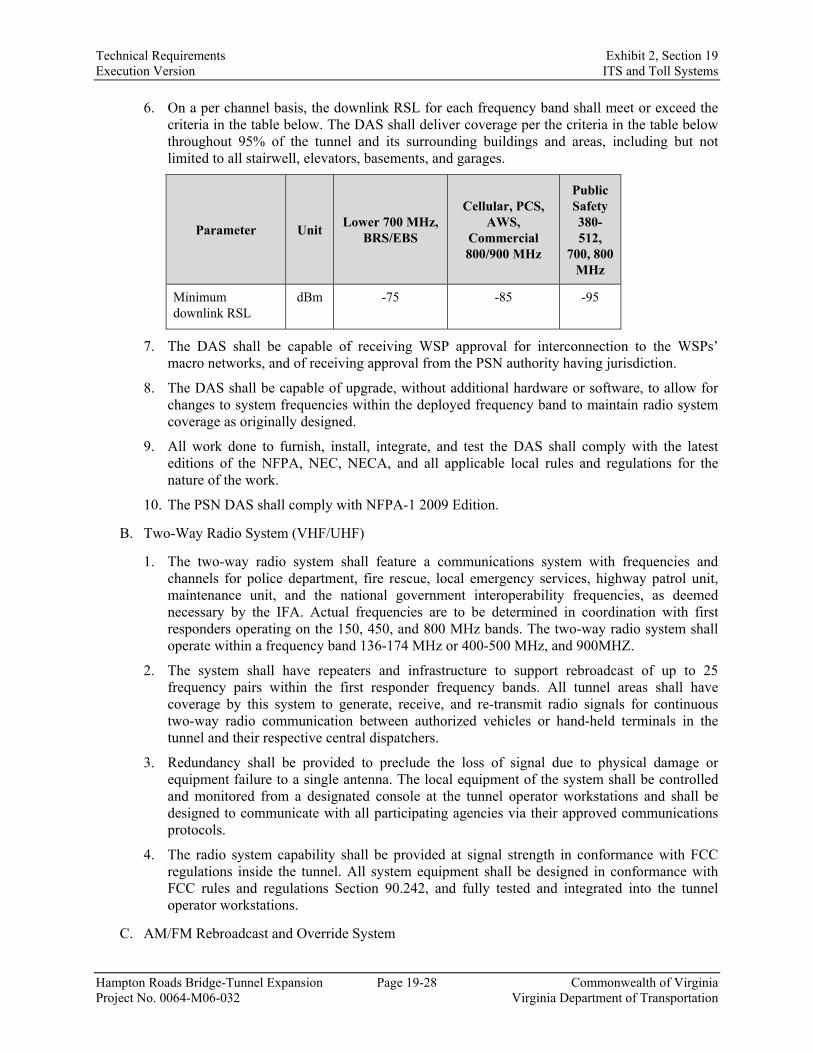
Technical Requirements Exhibit 2, Section 19 Execution Version ITS and Toll Systems
Hampton Roads Bridge-Tunnel Expansion Page 19-28 Commonwealth of Virginia Project No. 0064-M06-032 Virginia Department of Transportation
6. On a per channel basis, the downlink RSL for each frequency band shall meet or exceed the criteria in the table below. The DAS shall deliver coverage per the criteria in the table below throughout 95% of the tunnel and its surrounding buildings and areas, including but not limited to all stairwell, elevators, basements, and garages.
Parameter Unit Lower 700 MHz,
BRS/EBS
Cellular, PCS, AWS,
Commercial 800/900 MHz
Public Safety 380-512,
700, 800 MHz
Minimum downlink RSL
dBm -75 -85 -95
7. The DAS shall be capable of receiving WSP approval for interconnection to the WSPs’ macro networks, and of receiving approval from the PSN authority having jurisdiction.
8. The DAS shall be capable of upgrade, without additional hardware or software, to allow for changes to system frequencies within the deployed frequency band to maintain radio system coverage as originally designed.
9. All work done to furnish, install, integrate, and test the DAS shall comply with the latest editions of the NFPA, NEC, NECA, and all applicable local rules and regulations for the nature of the work.
10. The PSN DAS shall comply with NFPA-1 2009 Edition.
B. Two-Way Radio System (VHF/UHF)
1. The two-way radio system shall feature a communications system with frequencies and channels for police department, fire rescue, local emergency services, highway patrol unit, maintenance unit, and the national government interoperability frequencies, as deemed necessary by the IFA. Actual frequencies are to be determined in coordination with first responders operating on the 150, 450, and 800 MHz bands. The two-way radio system shall operate within a frequency band 136-174 MHz or 400-500 MHz, and 900MHZ.
2. The system shall have repeaters and infrastructure to support rebroadcast of up to 25 frequency pairs within the first responder frequency bands. All tunnel areas shall have coverage by this system to generate, receive, and re-transmit radio signals for continuous two-way radio communication between authorized vehicles or hand-held terminals in the tunnel and their respective central dispatchers.
3. Redundancy shall be provided to preclude the loss of signal due to physical damage or equipment failure to a single antenna. The local equipment of the system shall be controlled and monitored from a designated console at the tunnel operator workstations and shall be designed to communicate with all participating agencies via their approved communications protocols.
4. The radio system capability shall be provided at signal strength in conformance with FCC regulations inside the tunnel. All system equipment shall be designed in conformance with FCC rules and regulations Section 90.242, and fully tested and integrated into the tunnel operator workstations.
C. AM/FM Rebroadcast and Override System

Technical Requirements Exhibit 2, Section 19 Execution Version ITS and Toll Systems
Hampton Roads Bridge-Tunnel Expansion Page 19-29 Commonwealth of Virginia Project No. 0064-M06-032 Virginia Department of Transportation
1. The AM/FM rebroadcast and override system shall feature a commercial radio rebroadcast system through the tunnel capable of rebroadcasting all commercial radio stations that can be received at the tunnel portals.
2. The radio rebroadcast and override system shall include override capabilities, permitting a tunnel operator to override all commercial frequencies to convey instructions to motorists for traffic and emergency response instructions. All override programming shall originate from any PCR or SCR operator workstations.
3. Redundancy shall be provided to preclude the loss of signal due to physical damage or equipment failure to a single antenna. The local equipment of the rebroadcast system shall be controlled and monitored from a designated console at the tunnel operator workstations and shall be designed to communicate with all participating agencies via their approved communications protocols.
4. The rebroadcast and override capability shall be provided at signal strength in conformance with FCC regulations inside the tunnel. No degradation of the radio system shall be permitted by the rebroadcast system. All rebroadcast and override equipment shall be designed in conformance with FCC rules and regulations Section 90.242, and fully tested and integrated into the tunnel operator workstations.
5. The existing and new AM/FM rebroadcast and override systems shall be integrated into a single system at the operator workstation level. The AM/FM rebroadcast and override system shall allow for override messages to be broadcast in one or all of the existing and new tunnel(s). The AM/FM rebroadcast and override system shall also allow for independent messages to be transmitted simultaneously in the existing and new tunnel(s).
19.4.16. Fiber Optic Cable
A. Fiber optic cable systems shall be provided in accordance with the VDOT Road and Bridge Specifications, Section 808.
1. The Design-Builder shall provide fiber optic cable system to accommodate both directions of travel end-to-end (Hampton side to Norfolk side) on the new bridge-tunnel.
2. The Design-Builder shall provide a minimum of two 96 fiber single-mode cables to connect ITS and SCADA systems with the PCR and SCR. Device distribution shall be designed/configured for redundancy using two or more physically separated cables to form rings of separate ITS and SCADA networks and devices, such that a single cable cut/break does not disconnect any of the proposed devices along the new bridge-tunnel.
3. A redundant connection shall be made with the existing bridge-tunnel ITS and SCADA networks such that a single cable cut/break does not break the connection with the current devices. In both the cities of Hampton and Norfolk, lateral connections to the existing tunnel system shall be configured to provide a loop from the existing tunnel communications system to the proposed tunnel communications system while also providing connectivity to the PCR and SCR. The redundancy shall result in a connection to the existing bridge-tunnel devices’ fiber network from both the Hampton side and the Norfolk side to facilitate localized rings connecting to the PCR and SCR.
4. The Design-Builder shall design the fiber optic communication conduit system (size and count) to meet the needs of the existing and proposed ATMS and ITS infrastructure, while providing the spare conduits needed for future tolling and regional communications described

Technical Requirements Exhibit 2, Section 19 Execution Version ITS and Toll Systems
Hampton Roads Bridge-Tunnel Expansion Page 19-30 Commonwealth of Virginia Project No. 0064-M06-032 Virginia Department of Transportation
in Section 19.4.7 and additional spares for future needs as described in Section 27 of these Technical Requirements.
5. The Design-Builder shall maintain the existing fiber communication network and keep it operational at all times for the duration of construction, unless otherwise authorized by the Department. Additions, modifications, or adjustments to the fiber communication network and interfaces shall seamlessly reside and be fully interoperable with legacy networks and the VDOT ATMS software during and immediately after construction.
6. The ITS and SCADA network fiber optic cables shall be routed through both new tunnels for all ITS and SCADA systems communications requirements. Provide two 4-inch conduits encased in 4 inches of concrete, with 2-hour fire rated junction/splice boxes routed through the egress corridor plenum or egress corridor of both new tunnels, for the entire length of the tunnels. Provide three 1-1/4-inch low smoke zero halogen inner ducts in all 4-inch conduits. The ITS and SCADA network fiber optic cable shall be routed as “in” and “out” fiber optic cable loops in two separate 2-inch Type 316 stainless steel electrical metallic tubing (EMT) from the 2-hour fire rated junction box to the respective ITS and SCADA cabinets. One 2-inch conduit shall be for the “in” loop fiber cable and the second 2-inch conduit for the “out” fiber loop cable. Any deviation requires authorization in writing from the Department.
19.4.17. Installation
A. Install ITS in accordance with VDOT Standards, NFPA 70, and NFPA 502.
B. All associated wiring, cables, and/or conductors serving the tunnel and tunnel egress corridor and stairs shall be considered “Emergency Circuits with respect to NFPA 502” and MUST comply with the requirements of NFPA 502-2014, Chapter 12, Sections 12.1.2 and 12.2.1.3 or as modified by the current edition of NFPA 502.
C. Refer to Technical Requirement 27 for additional installation requirements.
19.4.18. Testing
A. The Design-Builder shall provide detailed test plans for all testing. The test plans must test the entire ITS and systems, including all equipment devices, software, and wiring.
B. The Design-Builder shall provide a detailed test plan for testing each of the new ITS operating software.
C. The Design-Builder shall provide a detailed procedure and test plan for implementing the replacement of the existing ITS operating software, as necessary.
D. The Design-Builder shall submit detailed procedures for all inspections and tests to be performed.
E. Testing and inspection for all components (equipment and cable) of the ITS system shall progress through the following four stages of testing.
1. Factory Acceptance Test. The first test shall be the factory acceptance test. As part of its submittals, the Design-Builder shall develop a plan which assembles, configures, and connects all equipment in a manner that simulates the complete Project. The Design-Builder shall then perform extensive testing to demonstrate that the hardware and system work as intended. The factory test shall have an unwitnessed phase, where the Design-Builder shall perform the tests themselves and submit signed test forms documenting the results. After certifying that the test has passed, a witnessed test shall be scheduled with the Department. The FAT must take place within the continental United States.

Technical Requirements Exhibit 2, Section 19 Execution Version ITS and Toll Systems
Hampton Roads Bridge-Tunnel Expansion Page 19-31 Commonwealth of Virginia Project No. 0064-M06-032 Virginia Department of Transportation
2. Local Equipment Test. Once the equipment has been fully exercised as part of the FAT and installed according to the Contract Documents, the Design-Builder shall perform a local site test. This test shall verify that the equipment has not been damaged in shipment and has been installed properly. To the extent possible, the equipment shall be exercised locally to demonstrate full functionality. This test shall be witnessed by the Department.
3. Remote Equipment Test. After passing the local equipment test, the Design-Builder shall demonstrate that the equipment can function as a part of a complete system. From a designated control point, the Design-Builder shall exercise the remote equipment and demonstrate full functionality. This test shall be witnessed by the Department.
4. Final System Acceptance Test. The final test of the system shall be a final system acceptance test. This test shall be an endurance test, requiring flawless operation for the designated time period as described below.
F. Factory testing can use the manufacturer’s standard factory tests or be developed by the Design-Builder.
G. Local equipment tests and remote equipment tests shall be developed by the Design-Builder and submitted to the Department for acceptance.
H. Final system acceptance testing shall follow all the inspection and tests listed in ANSI/NETA ATS (current edition) Standard for Acceptance Testing Specifications for Electrical Power Equipment and Systems, Section 8 System Function Tests, and shall be developed by the Design-Builder to demonstrate that all equipment and systems operate as specified, and submitted for Department acceptance.
I. The Design-Builder shall submit detailed certified inspection and test reports for all inspections and tests performed.
J. ITS/TMS Testing
1. The Design-Builder shall conduct system burn-in testing. Three months prior to testing, the Design-Builder shall submit to the Department for acceptance a test strategy for the TMS that shall include as a minimum the following elements.
a. Scope, requirements, and objectives of testing.
b. Overall high-level plan for testing the TMS, including the test stages, processes, and scheduling of all tests.
c. Roles and responsibilities of all those involved with the testing program and any dependencies on third parties, including Department personnel. Testing and commissioning, where applicable, shall be based on the application of a systems engineering methodology such as ANSI/GEIA EIA-632.
d. Test series that shall demonstrate compliance with the performance requirements through a test plan and procedures.
e. Testing strategy document that details how the testing plan will be implemented to demonstrate conformance of the proposed solution to the various functional, technical, and performance requirements.
f. Test plan document that describes how the testing strategy will be executed to demonstrate the various functional, technical, and performance requirements for each ITS device installed on the project in order to document operational compliance with manufacturer requirements and these special requirements.

Technical Requirements Exhibit 2, Section 19 Execution Version ITS and Toll Systems
Hampton Roads Bridge-Tunnel Expansion Page 19-32 Commonwealth of Virginia Project No. 0064-M06-032 Virginia Department of Transportation
i. Test specifications for each of the test cycles.
ii. Checklist consisting of item being tested, expected result, pass/fail, remarks, list of deficiencies and signatures.
iii. User Acceptance Test shall be completed at least 30 days before the Final Completion Date identified in the Design-Builder’s Baseline Schedule.
K. The following testing requirements apply to all provided ITS equipment.
1. Inspection, integration, and testing involves a three-tier sequential process that consists of stand-alone functionality, system operation, user acceptance testing, and system burn-in testing.
2. Stand-alone testing requires field acceptance at the device and cabinet level. System operational testing requires acceptance at the communication hub and TMC levels. User acceptance testing shall successfully demonstrate that users at the TMC can fully control all aspects of the ITS. System burn-in testing requires continuous operation of the system without major or catastrophic failure for 30 consecutive days, which must occur prior to Final Completion. The Design-Builder shall make arrangements for the witnessing of tests by the Department staff or representatives by providing notification 7 days prior to scheduled test.
3. The Design-Builder shall be responsible for establishing and executing a plan for inspecting, integrating, and testing of all communications infrastructure and ITS device components furnished and installed for the Project. The QAM shall be responsible for ensuring that the inspection, integration, and testing plan established by the Design-Builder and accepted by the Department is properly executed, variances are reported, and corrective actions are made.
4. The Design-Builder shall supply written test procedures for Department acceptance a minimum of 30 days before testing can be started. The Design-Builder shall submit reports for all testing levels to verify procedures followed, results recorded, timetable, and action required. The testing reports shall include relevant information such as calibration data of all test equipment, charts, graphs, evidence, photographs, failure analysis, corrective action, traceability and audit trail, and certification signature of the QAM and Commissioning Agent as detailed in Technical Requirement 34.
5. The Design-Builder shall submit a schedule for system burn-in testing that shall be performed over a 30 consecutive day period under real-world operation conditions without system failure. The system shall not lock up, fail, or crash due to use, operator entry of data, or equipment malfunction during the 30 days. Operators will record any deficiency as it occurs and the Department may employ a third party to inspect the system and record any deficiencies. Any failure of Design-Builder supplied equipment or discovery of deficiency that causes a system failure shall be cause to halt and repeat the system burn-in test in its entirety for another full 30-day period after correction of the deficiency.
6. During system burn-in testing, the Design-Builder shall respond to any issues within 4 hours of notification from the Department. All repairs shall be completed within 48 hours, with the exception of communication failures that shall be completed within 24 hours.
7. The Design-Builder shall provide manufacturer’s warranties on all furnished equipment for material and workmanship that are customarily issued by the equipment manufacturer. The warranty period shall commence from successful completion of the user acceptance testing.
8. Upon the completion of device integration by the Department, the provided equipment shall be tested to demonstrate the full functionality of all required features for all installed field devices using the VDOT ATMS software. The testing shall take place at the primary control

Technical Requirements Exhibit 2, Section 19 Execution Version ITS and Toll Systems
Hampton Roads Bridge-Tunnel Expansion Page 19-33 Commonwealth of Virginia Project No. 0064-M06-032 Virginia Department of Transportation
room in the TOC building on the VDOT ATMS network for devices on the general purpose lanes. The Department shall review and accept the device configuration settings for compatibility with its VDOT ATMS prior to the commencement of testing.
9. The Design-Builder shall coordinate and support the Department to integrate the devices and monitoring software with its VDOT ATMS and to update any configurations as necessary.
L. The Design-Builder shall provide the Department with a sample unit of all ITS devices requiring integration with the VDOT ATMS software, including CCTV cameras, VDSs, and informational DMS.
M. The following documents shall be provided to the Department for review and authorization and acceptance according to the Design-Builder’s Baseline Schedule. Final system acceptance and design as-built documentation shall be provided and accepted before service commencement.
1. Technical specifications shall be a document or documents that specify the technical requirements of the ITS elements to be integrated into the ATMS.
2. Product cut/specification sheets shall show the type, model, and specifications for the ITS equipment the Design-Builder plans to use for the ATMS.
3. Network architecture shall document all interconnects and information flows for the network. The Design-Builder shall ensure the network architecture takes into account, and is coordinated with, the toll system integrator and the Department’s regional ITS architecture.
4. Project As-Built Drawings shall document the communications network design for the ITS and TMS. The documentation shall include, but not be limited to: plans, drawings, technical specifications for equipment, fiber optic splicing details, proposed IP addressing schema changes, and maintenance manuals.
5. Testing and integration strategy shall establish the principles of, and the Design-Builder’s approach to, the testing and integration of the TMS/ITS and related interfaces, including the integration phases, test stages, test processes, and conditions for moving from one test stage to the next (e.g., testing entrance and exit criteria).
19.5. Spares A. The Design-Builder shall provide spare parts and maintenance products of at least 10% quantity
for each component/system listed below, but not less than one of each item or as required in the VDOT Road and Bridge Specifications, whichever is greater.
a. AM/FM rebroadcast system major components (power supplies, AM power amplifier, FM power amplifier, AM/FM channelizer module).
b. CCTV cameras of each type (traffic fixed and PTZ security fixed and PTZ).
c. DMS as required by VDOT Road and Bridge Specifications.
d. LUS of each type major components (power supplies, controllers, sign modules).
e. Overheight vehicle detector units and controllers.
f. Vehicle detectors of each type (detector unit and controllers).
B. Design-Builder shall provide a spare parts and maintenance products (supplies) listing for all ITS equipment provided in accordance with manufacturer’s recommendation.

Technical Requirements Exhibit 2, Section 19 Execution Version ITS and Toll Systems
Hampton Roads Bridge-Tunnel Expansion Page 19-34 Commonwealth of Virginia Project No. 0064-M06-032 Virginia Department of Transportation
C. Spare parts list shall identify, at a minimum, original manufacturer, item name, item description, manufacturer part number, unit price, unit of issue, quantity recommended, and procurement lead time.
D. Provide all manuals, software licenses, specialty cables, specialty test equipment, or other specialty equipment and tools required to program, maintain or repair equipment.
E. Maintain provided spares in original containers with labels intact and legible, until delivery to the Department.
19.6. Deliverables The deliverables shall include the items listed in Table 19.6-1 for the Department’s consultation and written comment. All submittals shall be accompanied by an appropriate level of analysis and calculations to justify all engineering decisions made. The Department reserves the right to reject incomplete submittals.
Table 19.6-1 Deliverables
Deliverable
Number of Copies
Delivery Schedule1 Reference
Section Hard Copy
Electronic
FHWA Rule 940 compliance documents
5 1 19.4.5
Develop/verify Rule 940 test plans
5 1 19.4.5
Rule 940 Concept of Operation Document
5 1 19.4.5
Rule 940 Systems Engineering Analysis Document
5 1 19.4.5
Rule 940 System and Component Traceability Matrix
5 1 19.4.5
ITS Communications Network System Plan
5 1 19.4.7
Intelligent Transportation System Plan
5 1 19.4.10
Electronic Toll Collection
Conduit Plan 5 1 19.4.14
Wireless Communication System Plan
5 1 19.4.15
Develop Detailed Test Plans for ITS components and systems
5 1
and 5 CDs 19.4.18
Testing and Inspection of all components of ITS system
5 1 19.4.18
Note 1: Each stated deliverable is to be submitted on the schedule/date as stated in the Technical Requirements. If no submittal schedule/date is provided in the Technical Requirements, the Design-Builder shall provide a

Technical Requirements Exhibit 2, Section 19 Execution Version ITS and Toll Systems
Hampton Roads Bridge-Tunnel Expansion Page 19-35 Commonwealth of Virginia Project No. 0064-M06-032 Virginia Department of Transportation
submitted date for that deliverable in the Preliminary Schedule, to be approved by the Department and incorporated in the Baseline Schedule.

Technical Requirements Exhibit 2, Section 20 Execution Version Island Site Design
Hampton Roads Bridge-Tunnel Expansion Page 20-1 Commonwealth of Virginia Project No. 0064-M06-032 Virginia Department of Transportation
SECTION 20. ISLAND SITE DESIGN
20.1. General A. This Technical Requirement provides the requirements for the civil site layout for the islands. It is
the Design-Builder’s responsibility to identify and establish the location of existing utilities and underground material and equipment within the island perimeter. The Department has provided the Design-Builder all available existing information for the islands. The Department will provide reasonable access to the Design-Builder to establish the location and depths of underground utilities and material during design development.
20.2. References A. VDOT Design Manuals, Road and Bridge Standards, Specifications, and Reference Documents
listed herein, which are not all-inclusive:
1. VDOT Road and Bridge Standards, Vol. 1 and Vol. 2 including all revisions.
2. VDOT Utility Manual of Instructions.
3. VDOT Road Design Manual.
4. VDOT Drainage Manual.
5. VDOT Road and Bridge Specifications, including all revisions.
6. VDOT Hydraulic Design Advisories.
7. VDOT Water Quality Permit Manual.
8. VDOT Virginia Work Area Protection Manual.
9. Virginia Supplement to MUTCD.
10. VDOT GRIT.
B. Commonwealth of Virginia CPSM.
C. AASHTO Roadside Design Guide.
D. AASHTO Standard Specifications for Structural Supports for Highway Signs, Luminaries, and Traffic Signals.
E. Virginia Stormwater Management Handbook.
F. Virginia Erosion and Sediment Control Handbook.
G. Virginia Department of Health Waterworks Regulations.
H. VDEQ SCAT.
I. 28 CFR35 – Title II of the ADA.
J. 28CFR36 – Title III of the ADA.
K. ADA Standards for Accessible Design.
L. AWWA Standards.
M. AASHTO A Policy on Geometric Design of Highways and Streets.
N. AASHTO MUTCD.

Technical Requirements Exhibit 2, Section 20 Execution Version Island Site Design
Hampton Roads Bridge-Tunnel Expansion Page 20-2 Commonwealth of Virginia Project No. 0064-M06-032 Virginia Department of Transportation
20.3. Island Site Design Criteria
20.3.1. Tunnel Support and Facility Buildings
A. Ventilation Buildings
1. Access
a. Vehicular approach to the buildings shall not exceed 5% slope.
b. Pedestrian approach to the buildings shall meet ADA requirements.
2. Parking and Site Layout
a. The ventilation buildings will be located near each portal over the tunnel and are further described in Technical Requirement 35.
b. No personnel spaces are intended for use inside the ventilation buildings; therefore the only parking that will be required is for maintenance personnel.
i. A minimum of five parking spaces shall be provided at each ventilation building.
ii. At least one loading space will be provided for each loading dock.
3. Water and Sewer
a. Each ventilation building will require a minimum of one restroom facility as further described in Technical Requirement 35.
i. Potable water connections shall be provided and sized as required per design load calculations.
ii. Sanitary sewer shall be treated via drain field or disposed of at an authorized facility off the island in accordance with VDEQ SCAT regulations. The Design-Builder shall exhaust all options that eliminate the need for “pump and haul.” If pump and haul is the only viable option, the tank shall be sized to reduce the anticipated frequency to once per week.
4. Power and Communication
a. Concrete-encased duct banks shall be provided to the ventilation buildings to facilitate the power and communications cabling, as noted elsewhere in the Technical Requirements.
b. Duct banks shall be sized per the requirements of the building systems.
B. Traffic Operations Center Building
1. Access
a. Vehicular approach to the building loading bays shall not exceed 5% slope.
b. Pedestrian approach to the building shall meet ADA requirements.
2. Parking and Site layout
a. The TOC building will be the primary personnel building on the North Island. Drive aisles, ADA accessibility, and landscaping shall be per the CPSM.
i. A minimum of 24 standard parking spaces, with required ADA spaces, shall be provided at the TOC building.
b. The new TOC building will be located, as described in Technical Requirement 35,

Technical Requirements Exhibit 2, Section 20 Execution Version Island Site Design
Hampton Roads Bridge-Tunnel Expansion Page 20-3 Commonwealth of Virginia Project No. 0064-M06-032 Virginia Department of Transportation
Section 35.3.3.1.E, to serve the entire HRBT facility and shall be submitted to the Department for review and acceptance.
3. Water and Sewer
a. The TOC building will require restrooms and showers.
i. Potable water connections shall be provided and sized as required per design load calculations.
ii. Sanitary sewer shall be treated via drain field or disposed of at an authorized facility off the island in accordance with VDEQ SCAT regulations. The Design-Builder shall exhaust all options that eliminate the need for “pump and haul.” If pump and haul is the only viable option, the tank shall be sized to reduce the anticipated frequency to once per week.
4. Power and Communication
a. Concrete-encased duct banks shall be provided to the TOC building to facilitate the power and communications cabling, as noted elsewhere in the Technical Requirements.
b. Duct banks shall be sized per the requirements of the building systems.
C. Facility Maintenance Building
1. Access
a. Vehicular approach to the building bays shall not exceed 5% slope.
b. Pedestrian approach to the building shall meet ADA requirements.
2. Parking and Site Layout
a. The existing maintenance building on the North Island will be expanded to accommodate the complete facility. Eight additional parking spaces shall be provided.
b. The expanded maintenance building will require new restrooms and showers.
3. Water and Sewer
a. The existing water and sewer services shall be upgraded to accommodate the expanded building occupancy, including the addition of shower facilities.
4. Power and Communication
a. Concrete-encased duct banks shall be provided to the expanded facility maintenance building to facilitate the expanded power and communications cabling.
b. Duct banks shall be sized per the requirements of the expanded building systems.
D. New Garage Building
1. Access
a. Vehicular approach to the building bays shall not exceed 5% slope.
b. Pedestrian approach to the building shall meet ADA requirements.
2. Parking and Site Layout
a. A new garage building will be constructed on the North Island. A minimum of six parking spaces and two loading spaces shall be provided.
b. The garage building will be located on the North Island near the south end of the island.

Technical Requirements Exhibit 2, Section 20 Execution Version Island Site Design
Hampton Roads Bridge-Tunnel Expansion Page 20-4 Commonwealth of Virginia Project No. 0064-M06-032 Virginia Department of Transportation
3. Water and Sewer
a. The new garage building will not require restroom facilities.
i. Potable water connections shall be provided and sized as required per design load calculations.
ii. Sanitary sewer shall be treated via drain field or disposed of at an authorized facility off the island in accordance with VDEQ SCAT regulations. The Design-Builder shall exhaust all options that eliminate the need for “pump and haul.” If pump and haul is the only viable option, the tank shall be sized to reduce the anticipated frequency to once per week.
4. Power and Communication
a. Concrete-encased duct banks shall be provided to the new garage building to facilitate the power and communications cabling.
b. Duct banks shall be sized per the requirements of the building systems.
E. Crash House Buildings
1. Access
a. Vehicular approach to the building bays shall not exceed 5% slope.
b. Pedestrian approach to the building shall meet ADA requirements.
2. Parking and Site Layout
a. A minimum of four designated parking spaces, along with a 200-foot by 200-foot paved staging area, shall be provided for each crash house.
b. Crash house bays and staging area must be provided in unsecure area.
3. Water and Sewer
a. The crash house buildings will require restrooms and showers.
i. Potable water connections shall be provided and sized as required per design load calculations.
ii. Sanitary sewer shall be treated via drain field or disposed of at an authorized facility off the island in accordance with VDEQ SCAT regulations. The Design-Builder shall exhaust all options that eliminate the need for “pump and haul.” If pump and haul is the only viable option, the tank shall be sized to reduce the anticipated frequency to once per week.
4. Power and Communication
a. Concrete-encased duct banks shall be provided to the new crash house buildings to facilitate the power and communications cabling, as noted elsewhere in the Technical Requirements.
b. Duct banks shall be sized per the requirements of the building systems.
F. Island Inspection Booth Buildings
1. Access
a. Vehicular approach to the building shall not exceed 5% slope.
b. Pedestrian approach to the building shall meet ADA requirements.

Technical Requirements Exhibit 2, Section 20 Execution Version Island Site Design
Hampton Roads Bridge-Tunnel Expansion Page 20-5 Commonwealth of Virginia Project No. 0064-M06-032 Virginia Department of Transportation
2. Parking and Site Layout
a. New inspection booths will be required for the expanded facility. Current operation procedures do not require the need for parking at the booths. However, personnel will need to access the booths safely on foot.
3. Water and Sewer
a. Each island inspection booth building will require a minimum of one restroom facility.
i. Potable water connections shall be provided and sized as required per design load calculations.
ii. Sanitary sewer shall be treated via drain field or disposed of at an authorized facility off the island in accordance with VDEQ SCAT regulations. The Design-Builder shall exhaust all options that eliminate the need for “pump and haul.” If pump and haul is the only viable option, the tank shall be sized to reduce the anticipated frequency to once per week.
4. Power and Communication
a. Concrete-encased duct banks shall be provided to the island inspection booth buildings to facilitate the power and communications cabling, as noted elsewhere in the Technical Requirements.
b. Duct banks shall be sized per the requirements of the building systems.
20.4. Island Traffic Circulation
20.4.1. Island Connectivity
A. All buildings (existing and proposed) and parking lots shall be accessible by an asphalt paved roadway system, striped and signed to indicate traffic directions and flow design to service road (GS-9) standards.
1. Internal access road design shall accommodate a WB-67 truck at 10 mph.
2. Internal access roads with two-way traffic shall be a minimum of 24 feet wide with shoulders.
3. Internal access roads with one-way traffic shall be a minimum of 18 feet wide with shoulders.
B. A specific path shall be designated to allow emergency response vehicles, wrecker vehicles, and other site personnel direct access to each of the tunnels, without stopping or crossing tunnel traffic. Access to the tunnels shall be to and from the general purpose and HOT lanes, and shall be similar to existing access at the facility.
C. The Design-Builder shall provide a minimum of six WB-67 truck parking spaces on the South Island to accommodate over-height vehicle storage.
20.4.2. Acceleration/Deceleration Lanes
A. Acceleration lanes shall be provided at each roadway and bridge structure exiting the island to allow maintenance/operations personnel safe access from the islands into I-64 general purpose lanes in both the eastbound and westbound directions. Acceleration lanes shall be designed in accordance with the AASHTO, A Policy on Geometric Design of Highways and Streets, Section 10.9. for highway design speed of 60 mph.
B. Acceleration lanes should occur from the right travel lane, and any deviations to this must be supported by an analysis of island traffic circulation.

Technical Requirements Exhibit 2, Section 20 Execution Version Island Site Design
Hampton Roads Bridge-Tunnel Expansion Page 20-6 Commonwealth of Virginia Project No. 0064-M06-032 Virginia Department of Transportation
C. Shoulder widths approaching the island emergency vehicle access points in the eastbound direction approaching the north island and in the westbound direction approaching the South Island shall be as follows:
1. The right side shoulder adjacent to the general purpose lanes shall be the normal shoulder width.
2. The left side shoulder adjacent to the part time HOT lanes shall be a 12-foot wide shoulder for 200’ prior to the emergency access points, and tapering to the normal shoulder width beyond that (similar to the existing eastbound approach to the north island).
3. Any other shoulders shall be the normal shoulder width.
D. Shoulder widths entering and exiting the new tunnel portals, both on the left and right, shall be a 12-foot wide shoulder between the emergency vehicle access point to the beginning of the open cut approach structures, and taper at 30:1 from a 12-foot wide shoulder to the tunnel shoulder width.
E. Modifications to the existing tunnel open cut approach structures to accommodate acceleration or deceleration lanes are not required as part of the project scope. If modifications to the existing tunnel open cut approach structures are required by the Work, the Design-Builder shall provide acceleration or deceleration accommodations equal to or better than the existing accommodations.
20.4.3. Pavement Design
A. All pavement design (i.e., rigid, flexible) shall be per Technical Requirement 17.
20.4.4. Emergency Vehicle Access
A. The emergency response plan and vehicle circulation shall allow for emergency vehicle access to any point on the roadway, tunnel, and islands.
B. The Design-Builder shall provide emergency vehicle access at each end of each tunnel. The emergency vehicle access shall provide access to and from both the general purpose lanes and HOT lanes, in both directions, to and from each island without crossing the HOT lane buffer. Access points shall be sized to accommodate turning movements of fire and rescue vehicles, heavy-duty wreckers, and tractor trailers. The access shall be similar to the existing access at the facility.
20.5. Drainage
20.5.1. Drainage Criteria
A. The VDOT Drainage Manual shall be used to design all stormwater collection and conveyance systems.
B. The Design-Builder shall ensure existing tunnel facility drainage conveyance systems are accessible to an island outfall.
20.5.2. Site Grading
A. Grading of the islands shall be designed and constructed to provide positive drainage to properly located drainage inlets. The proposed grade elevation of the site shall meet the existing grade at the tie-in locations.

Technical Requirements Exhibit 2, Section 20 Execution Version Island Site Design
Hampton Roads Bridge-Tunnel Expansion Page 20-7 Commonwealth of Virginia Project No. 0064-M06-032 Virginia Department of Transportation
20.6. Stormwater Management A. The Virginia SWM Handbook shall be used for stormwater management related to water QC.
B. Stormwater controls shall be designed to part II C or II B technical criteria as identified in the Virginia Administrative Code, Section 9VAC25-870.
C. The Design-Builder shall take necessary measures to prevent exceedance of existing facility VPDES stormwater discharge permit limits, supplied as Supplemental Information.
D. The Design-Builder will coordinate activities with the Department to amend the existing VPDES permit for tunnel roadway drainage to include added tunnel roadway drainage discharges.
20.7. Site Lighting A. Exterior lighting for the new and expanded buildings, parking lots, drive aisles, and access roads
shall be per Technical Requirement 31.
20.8. Cell Provider Co-Location Facility
20.8.1. Co-location Area
A. A minimum 2,500 square foot contiguous area shall be set aside on both islands for cell providers to locate communications gear. Minimum length and width shall be 40 feet. This area shall be outside the VDOT secure perimeter and accessible to cell provider vendor contractors.
1. The co-location area shall have a stand-alone security fence that is not connected or tied into VDOT’s security fencing.
B. Dedicated duct banks shall be installed from the co-location area to portal of each tunnel, both existing and proposed. This duct bank system shall be used by the cell providers only.
1. Duct bank design will need to be coordinated with each cell provider vendor.
2. The Design-Builder shall provide a dedicated power source to the co-location area. The co-location area will be incorporated into VDOT’s power and backup power distribution system.
20.9. Existing Fuel Station and Tanks A. The Design-Builder shall ensure that the existing fuel station and tanks (both gasoline and diesel)
on the North Island are operational and accessible during the project construction. If these facilities are relocated as part of the Project, the Design-Builder shall provide equal or greater operational capacity and coordinate the new location with the Department as part of the island site design space planning effort described in this, Section 20.10.
B. The North and South Island emergency generators also have underground storage tanks that shall remain in service during the project construction.
20.10. Island Site Design Space Planning
A. The Design-Builder shall develop conceptual island site layouts for both islands that depict all tunnel and tunnel support facilities anticipated in the Technical Requirements. Island site layouts shall be submitted to the Department for review and acceptance.
B. The Design-Builder shall submit five scroll plans of its island site layouts to the Department for acceptance prior to initial detailed design of any elements the Project crosses through, on, or adjacent to the islands. Each island shall be shown in its entirety on one scroll plan at a scale that

Technical Requirements Exhibit 2, Section 20 Execution Version Island Site Design
Hampton Roads Bridge-Tunnel Expansion Page 20-8 Commonwealth of Virginia Project No. 0064-M06-032 Virginia Department of Transportation
clearly depicts the site, facilities, traffic circulation, parking and staging areas, signing, marking, and access ramps/entrances.
20.11. Deliverables
The deliverables shall include the items listed in Table 20.10-1 for the Department’s consultation and written comment. All submittals shall be accompanied by an appropriate level of analysis and calculations to justify all engineering decisions made. The Department reserves the right to reject incomplete submittals.
Table 20.10-1 Deliverables
Deliverable Number of Copies
Delivery Schedule Reference
Section Hard Copy Electronic
North Island Site Layout 5 1 Prior to detailed design 20.10
South Island Site Layout 5 1 Prior to detailed design 20.10

Technical Requirements Exhibit 2, Section 21 Execution Version Bridges and Structures
Hampton Roads Bridge-Tunnel Expansion Page 21-1 Commonwealth of Virginia Project No. 0064-M06-032 Virginia Department of Transportation
SECTION 21. BRIDGES AND STRUCTURES
21.1. Scope A. Table 21.1-1 presents the bridge structures anticipated to be widened, repaired/rehabilitated,
replaced, and newly constructed as shown within the RFP Concept Plans. This table is not all-inclusive nor is it a required approach of the Design-Builder. The Design-Builder shall address each structure with respect to adherence to this Technical Requirement. The Design-Builder shall design and construct each structure to comply with the requirements of the Project.
Table 21.1-1 Structures
Fed ID State ID Bridge Name Anticipated Action
20279 2800 Mallory St over I-64 Replace 20339 2827 HRBT North Approach Trestle (Existing EB) Replace 20355 2902 HRBT North Approach Trestle (Existing WB) Replace HRBT North Approach Trestle (New) New 20352 2866 HRBT South Approach Trestle (Existing EB) Replace 20353 2900 HRBT South Approach Trestle (Existing WB) Replace HRBT South Approach Trestle (EB) New 20909 2882 I-64 over Bayville St/13th view (EB) Widen & Repair/Rehabilitate 20911 2883 I-64 over Bayville St/13th view (WB) Widen & Repair/Rehabilitate 20913 2884 I-64 over Willoughby Bay (EB) Widen & Repair/Rehabilitate 20914 2885 I-64 over Willoughby Bay (WB) Widen & Repair/Rehabilitate 20931 2898 I-64 over 4th View St (EB) Widen & Repair/Rehabilitate 20929 2897 I-64 over 4th View St (WB) Widen & Repair/Rehabilitate 20825 2805 I-64 over Mason Creek Rd (EB) Widen & Repair/Rehabilitate 20823 2804 I-64 over Mason Creek Rd (WB) Widen & Repair/Rehabilitate 20850 2821 I-64 over 1st View St (EB) Widen & Repair/Rehabilitate 20839 2813 I-64 over 1st View St (WB) Widen & Repair/Rehabilitate 20873 2844 I-64 over Bay Ave (EB) Widen & Repair/Rehabilitate 20869 2836 I-64 over Bay Ave (WB) Widen & Repair/Rehabilitate 20925 2894 I-64 over Evans St (EB) Widen & Repair/Rehabilitate 20923 2893 I-64 over Evans St (WB) Widen & Repair/Rehabilitate 20921 2892 I-64 over Bayview Blvd (EB) Widen & Repair/Rehabilitate 20919 2891 I-64 over Bayview Blvd (WB) Widen & Repair/Rehabilitate 20928 2896 I-64 over Oastes Creek/Mason Creek (EB) Widen & Repair/Rehabilitate 20927 2895 I-64 over Oastes Creek/Mason Creek (WB) Widen & Repair/Rehabilitate 20917 2890 I-64 over Patrol Rd/New Gate Rd (EB) Widen & Repair/Rehabilitate 20915 2889 I-64 over Patrol Rd/New Gate Rd (WB) Widen & Repair/Rehabilitate 20902 2876 I-64 over Granby St (EB) Widen & Repair/Rehabilitate

Technical Requirements Exhibit 2, Section 21 Execution Version Bridges and Structures
Hampton Roads Bridge-Tunnel Expansion Page 21-2 Commonwealth of Virginia Project No. 0064-M06-032 Virginia Department of Transportation
Fed ID State ID Bridge Name Anticipated Action
20892 2867 I-64 over Little Creek Road Widen & Repair/Rehabilitate 20900 2873 I-64 over I-564 Widen & Repair/Rehabilitate
B. Scope Description
1. Mallory Street over I-64 (Structure 2800) – Bridge Replacement
The existing bridge shall be demolished and replaced with a new structure. The replacement bridge is to be designed to meet the width and configuration detailed on the bridge typical section provided in the RFP Concept Plans. The minimum vertical clearance to be provided, during and after construction, over I-64 WB and I-64 EB shall be 16 feet 6 inches.
Construction of the proposed bridge and demolition of the existing bridge shall be staged as necessary to maintain one 11-foot lane of traffic and 1-foot shoulder in each direction, and a 5-foot 6 inch pedestrian walkway protected by barrier with fencing on Mallory Street at all times; and to meet other requirements in accordance with the accepted Traffic Management Plan developed by the Design-Builder. Additionally, the Design-Builder must provide continuous and safe access for pedestrian and bicycle traffic between the limits of construction. Temporary and final pedestrian access must comply with ADA Accessibility Guidelines for State and Local Government Facilities.
VDOT standard CPSR bridge railing and pedestrian fencing BPF Type B and Type C shall be designed and constructed in accordance with the VDOT Manual of the Structure and Bridge Division. The steel railing shall be galvanized and powder-coated (black, federal color no. 37038) in accordance with the SP for Powder Coated Galvanized Railing for Design-Build and PPTA contracts.
Existing utilities supported on the bridge shall be maintained during bridge replacement. The bridge shall be designed to support the utilities and to include their associated structural supports and/or hanger system. Additional conduit and cable may be required in the overall project design and based upon coordination with VDOT utilities.
2. I-64 EB & WB North Approach Trestles (Structures 2827 & 2902), & I-64 EB & WB South Approach Trestles (Structures 2866 & 2900) – Bridge Replacements
The existing north and south approach trestle bridges shall be demolished and replaced with new structures. The replacement bridges will carry I-64 WB and shall be designed to meet the minimum lane configuration requirements in Technical Requirement 17 and any required shoulders and buffers. The 2-foot shoulder, noted as part of the part-time HOT lane in Section 17.3.2.B of Technical Requirement 17, is not applicable on these trestles.
Construction of the proposed bridges and demolition of the existing bridges shall be staged in accordance with the accepted Traffic Management Plan developed by the Design-Builder. The new bridges may be constructed on new alignments to avoid conflicts with the existing structures and shall tie into the existing tunnels. The revised alignments shall meet all requirements of Technical Requirement 17 and shall follow the submittal process to the Department for authorization.
Existing utilities supported on the bridges shall be maintained during bridge replacements. The bridges shall be designed to support the utilities and to include their associated structural supports and/or hanger systems. Working fire hydrants protected by bollards shall be provided at each end of the new bridges for incident response. Additional conduit and cable may be required in the overall project design and based upon coordination with VDOT utilities.

Technical Requirements Exhibit 2, Section 21 Execution Version Bridges and Structures
Hampton Roads Bridge-Tunnel Expansion Page 21-3 Commonwealth of Virginia Project No. 0064-M06-032 Virginia Department of Transportation
3. I-64 EB North & South Approach Structures – New Bridges
New bridges shall carry I-64 EB and shall be designed to meet the minimum lane configuration requirements in Technical Requirement 17 and any required shoulders and buffers. The 2-foot shoulder noted as part of the part-time HOT lane in Section 17.3.2.B of Technical Requirement 17 is not applicable on these trestles.
Construction of the proposed bridges shall be staged in accordance with the accepted Traffic Management Plan developed by the Design-Builder.
The bridges shall be designed to support utilities required in the overall project design and based upon coordination with VDOT utilities. Working fire hydrants protected by bollards shall be provided at each end of the new bridges for incident response.
4. I-64 EB (Structure 2882) & I-64 WB (Structure 2883) over Bayville St/13th View St – Bridge Widenings
Proposed improvements for the existing bridges shall consist of partial demolition, widening and modification to the superstructure, widening and modification of existing abutments and piers, and repairs to the existing superstructure and substructure.
The existing minimum vertical clearance is 16 feet 8 inches and the minimum vertical clearance to be provided during and after construction shall be 16 feet 2 inches. The vertical clearance to elements of the existing bridge to remain shall not be reduced.
For the bridge widening, simple span structural steel girders/beams shall be used and designed as composite with the cast-in-place deck. The use of stay-in-place deck forms is permitted but shall not be used in the first bay between the existing girder and the proposed girder.
The existing bridge decks are currently overlaid with an epoxy coating. The existing bridge decks shall receive a rigid concrete overlay in accordance with the VDOT Road and Bridge Specifications. Deck repair work also includes Type C patching to be performed in accordance with VDOT requirements and prior to milling and hydro-demolition operations. Repair of the existing decks shall include removal and replacement of the original concrete deck to a minimum depth of 1.75 inches below the existing roadway surface. The maximum depth of removal using Type A milling shall be 1.25 inches from the existing roadway surface. The remaining depth to be removed shall be performed by Type A hydro-demolition. The new rigid overlay shall have a depth of 2.0 inches (0.25-inch overfill) and shall consist of Latex Modified, High Early Strength Latex Modified, or Very Early Strength Latex Modified Concrete, depending upon the proposed work plan, sequence of construction, and maintenance of traffic plan.
The new and existing portions of the bridge deck shall be constructed or retrofitted to be continuous at pier locations, as provided in the VDOT Manual of the Structure and Bridge Division, Part 2, Section 32.09, and shall be configured to contain deck drainage at barrier joint locations. The joints at both ends of the bridge between the bridge deck and abutment backwall shall be eliminated using the guidance and details in the VDOT Manual of the Structure and Bridge Division, Part 2, Chapter 32. The Design-Builder may propose an alternative detail for Department consideration and acceptance.
Existing structural steel shall be re-coated in accordance with VDOT requirements, including complete removal and disposal of the existing coating. New and existing structural steel shall be painted to match the color of the existing coating system.
Existing utilities are currently supported from the bridges and shall be maintained during bridge widenings. If necessary, the bridge widenings shall be designed to support the utilities

Technical Requirements Exhibit 2, Section 21 Execution Version Bridges and Structures
Hampton Roads Bridge-Tunnel Expansion Page 21-4 Commonwealth of Virginia Project No. 0064-M06-032 Virginia Department of Transportation
and to include their associated structural supports and/or hanger systems. Existing utilities not being replaced may need to be repaired.
All repair work shall be done in accordance with the VDOT Road and Bridge Specifications and referenced SPs. A list of repair items is anticipated to include but not be limited to the following.
Table 21.1-2 Repair Items
Repair Item Description Repair Item Description
Remove Portion of Existing Structure Disposal of materials
Type C Patching Jacking and blocking beams
Type A Milling Anchor bolt replacement
Type A Hydro-Demolition Reconstruct bridge seat
Furnish & Place Rigid Concrete Overlay Clean and paint existing steel bearings
Crack Repair Steel bearing replacement
Deck Slab Closure Epoxy injection crack sealing
Back Wall Reconstruction Concrete surface repair (substructure)
Steel Beam Repair Embedded galvanic anodes
Prepare and Overcoat Existing Structure Slope Protection Repairs
5. I-64 EB (Structure 2884) & I-64 WB (Structure 2885) over Willoughby Bay – Bridge Widenings
Proposed improvements for the existing bridges shall consist of partial demolition, widening and modification to the superstructure, widening and modification of existing abutments and piers, and repairs to the existing superstructure and substructure. The existing north parapet (inside) on I-64 EB shall be removed and replaced with VDOT standard 42-inch high concrete parapet. The existing north parapet (outside) on I-64 WB may be left in place based on the results of the noise barrier analysis. If the potential sound barrier wall is required, a new standard VDOT parapet will be required for the entire length on the outside of the bridge, regardless of the length of sound barrier wall required on the bridge. If the potential sound barrier wall is not required, existing parapet shall be waterproofed with epoxy per VDOT Specifications.
The existing fender system located between bents 62 and 63 shall be removed in its entirety. Fender support piles shall be removed at the mudline. The disconnected navigation lighting on the superstructure and associated conduits shall also be removed. Any proposed work shall not reduce available clearance or restrict the existing access through the channel span unless approved by the USCG.
Existing sign structures and sign structure supports currently located on the bridges shall not be re-used.
For the bridge widening, simple span prestressed beams shall be used and designed as composite with the cast-in-place deck. The use of stay-in-place deck forms is permitted but shall not be used in the first bay between the existing girder and the proposed girder.
The existing bridge decks are currently overlaid with an epoxy coating. The existing bridge decks shall receive a rigid concrete overlay in accordance with the VDOT Road and Bridge

Technical Requirements Exhibit 2, Section 21 Execution Version Bridges and Structures
Hampton Roads Bridge-Tunnel Expansion Page 21-5 Commonwealth of Virginia Project No. 0064-M06-032 Virginia Department of Transportation
Specifications. Deck repair work also includes Type C patching to be performed in accordance with VDOT requirements and prior to milling and hydro-demolition operations. Existing deck repairs shall include removal and replacement of the original concrete deck to a minimum depth of 1 inch below the top mat of reinforcing steel over the entire surface of the deck, and shall be performed by Type B hydro-demolition. The new rigid overlay shall have a depth of 2.0 inches over the existing top of concrete deck (0.25-inch overfill) and shall consist of Latex Modified, High Early Strength Latex Modified, or Very Early Strength Latex Modified Concrete, depending upon the proposed work plan, sequence of construction, and maintenance of traffic plan.
The new and existing portions of the bridge deck shall be constructed or retrofitted to be continuous at pier locations to the maximum extent possible, as provided in the Manual of the VDOT Structure and Bridge Division, Part 2, Section 32.09, and shall be configured to contain deck drainage at barrier joint locations. At locations where joints cannot be eliminated, existing joints shall be removed and replaced with new elastomeric expansion dams (Type F2) installed the full width of the existing bridge plus the new widened portions. The joints at both ends of the bridge between the bridge deck and abutment backwall shall be eliminated using the guidance and details in the VDOT Manual of the Structure and Bridge Division, Part 2, Chapter 32. The Design-Builder may propose an alternative detail for Department consideration and acceptance.
Existing prestressed beams will require protective and restorative repairs. Anticipated repair work includes concrete beam repairs, fiber reinforced polymer wraps, crack repairs, and beam end repairs.
Substructure repairs shall include pile jackets of 24-inch square piles. All existing pile jackets shall be replaced.
Existing utilities are currently supported from the bridges and shall be maintained during bridge widenings. If necessary, the bridge widenings shall be designed to support the utilities and to include their associated structural supports and/or hanger systems. Existing utilities not being replaced may need to be repaired.
All repair work shall be done in accordance with the VDOT Road and Bridge Specifications and referenced SPs. A list of repair items is anticipated to include but not be limited to the following.
Table 21.1-3 Repair Items
Repair Item Description Repair Item Description
Remove Portion of Existing Structure Waterproofing – epoxy resin
Type C Patching Jacking and blocking beams
Type B Hydro-Demolition Anchor bolt replacement
Furnish & Place Rigid Concrete Overlay Reconstruct bridge seat
Crack Repair Clean and paint existing steel bearings
Deck Slab Closure Steel bearing replacement
Back Wall Reconstruction Epoxy injection crack sealing
Elastomeric Expansion Dams Concrete surface repair (substructure)
Concrete Beam Repairs FRP jacket 24” square piles

Technical Requirements Exhibit 2, Section 21 Execution Version Bridges and Structures
Hampton Roads Bridge-Tunnel Expansion Page 21-6 Commonwealth of Virginia Project No. 0064-M06-032 Virginia Department of Transportation
Repair Item Description Repair Item Description
Fiber Reinforced Polymer Wraps Embedded galvanic anode
6. I-64 EB (Structure 2898) & I-64 WB (Structure 2897) over 4th View St – Bridge Widenings
Proposed improvements for the existing bridges shall consist of partial demolition, widening and modification to the superstructure, widening and modification of existing abutments and piers, and repairs to the existing superstructure and substructure.
The existing minimum vertical clearance is 16 feet 6 inches and the minimum vertical clearance to be provided during and after construction shall be 15 feet 11 inches. The vertical clearance to elements of the existing bridge to remain shall not be reduced.
For the bridge widening, simple span structural steel girders/beams shall be used and designed as composite with the cast-in-place deck. The use of stay-in-place deck forms is permitted but shall not be used in the first bay between the existing girder and the proposed girder.
The existing bridge decks are currently overlaid with an epoxy coating. The existing bridge decks shall receive a rigid concrete overlay in accordance with the VDOT Road and Bridge Specifications. Deck repair work also includes Type C patching to be performed in accordance with VDOT requirements and prior to milling and hydro-demolition operations. Repair of the existing decks shall include removal and replacement of the original concrete deck to a minimum depth of 1.75 inches below the existing roadway surface. The maximum depth of removal using Type A milling shall be 1.25 inches from the existing roadway surface. The remaining depth to be removed shall be performed by Type A hydro-demolition. The new rigid overlay shall have a depth of 2.0 inches (0.25-inch overfill) and shall consist of Latex Modified, High Early Strength Latex Modified, or Very Early Strength Latex Modified Concrete, depending upon the proposed work plan, sequence of construction, and maintenance of traffic plan.
The new and existing portions of the bridge deck shall be constructed or retrofitted to be continuous at pier locations, as provided in the VDOT Manual of the Structure and Bridge Division, Part 2, Section 32.09, and shall be configured to contain deck drainage at barrier joint locations. The joints at both ends of the bridge between the bridge deck and abutment backwall shall be eliminated using the guidance and details in the VDOT Manual of the Structure and Bridge Division, Part 2, Chapter 32. The Design-Builder may propose an alternative detail for Department consideration and acceptance.
Existing structural steel shall be re-coated in accordance with VDOT requirements, including complete removal and disposal of the existing coating. New and existing structural steel shall be painted to match the color of the existing coating system.
Existing utilities are currently supported from the bridges and shall be maintained during bridge widenings. If necessary, the bridge widenings shall be designed to support the utilities and to include their associated structural supports and/or hanger systems. Existing utilities not being replaced may need to be repaired.
All repair work shall be done in accordance with the VDOT Road and Bridge Specifications and referenced SPs. A list of repair items is anticipated to include but not be limited to the following.

Technical Requirements Exhibit 2, Section 21 Execution Version Bridges and Structures
Hampton Roads Bridge-Tunnel Expansion Page 21-7 Commonwealth of Virginia Project No. 0064-M06-032 Virginia Department of Transportation
Table 21.1-4 Repair Items
Repair Item Description Repair Item Description
Remove Portion of Existing Structure Prepare and overcoat existing structure
Type C Patching Disposal of materials
Type A Milling Jacking and blocking beams
Type A Hydro-Demolition Clean and paint existing steel bearings
Furnish & Place Rigid Concrete Overlay Steel bearing replacement
Crack Repair Epoxy injection crack sealing
Deck Slab Closure Concrete surface repair (substructure)
Back Wall Reconstruction Slope protection repairs
Steel Beam Repair Embedded galvanic anode
7. I-64 EB (Structure 2805) & I-64 WB (2804) over Mason Creek Road – Bridge Widenings
Proposed improvements for the existing bridges shall consist of partial demolition, widening and modification to the superstructure, widening and modification of existing abutments and piers, and repairs to the existing superstructure and substructure.
The existing minimum vertical clearance is 16 feet 5 inches and the minimum vertical clearance to be provided during and after construction shall be 16 feet 3 inches. The vertical clearance to elements of the existing bridge to remain shall not be reduced.
For the bridge widening, simple span structural steel girders/beams shall be used and designed as composite with the cast-in-place deck. The use of stay-in-place deck forms is permitted but shall not be used in the first bay between the existing girder and the proposed girder.
The existing bridge decks are currently overlaid with an epoxy coating. The existing bridge decks shall receive a rigid concrete overlay in accordance with the VDOT Road and Bridge Specifications. Deck repair work also includes Type C patching to be performed in accordance with VDOT requirements and prior to milling and hydro-demolition operations. Repair of the existing decks shall include removal and replacement of the original concrete deck to a minimum depth of 1.75 inches below the existing roadway surface. The maximum depth of removal using Type A milling shall be 1.25 inches from the existing roadway surface. The remaining depth to be removed shall be performed by Type A hydro-demolition. The new rigid overlay shall have a depth of 2.0 inches (0.25-inch overfill) and shall consist of Latex Modified, High Early Strength Latex Modified, or Very Early Strength Latex Modified Concrete, depending upon the proposed work plan, sequence of construction, and maintenance of traffic plan.
The new and existing portions of the bridge deck shall be constructed or retrofitted to be continuous at pier locations to the maximum extent possible, as provided in the VDOT Manual of the Structure and Bridge Division, Part 2, Section 32.09, and shall be configured to contain deck drainage at barrier joint locations. At locations where joints cannot be eliminated, existing joints shall be removed and replaced with new elastomeric expansion dams (Type F2) installed the full width of the existing bridge plus the new widened portions. The joints at both ends of the bridge between the bridge deck and abutment backwall shall be eliminated using

Technical Requirements Exhibit 2, Section 21 Execution Version Bridges and Structures
Hampton Roads Bridge-Tunnel Expansion Page 21-8 Commonwealth of Virginia Project No. 0064-M06-032 Virginia Department of Transportation
the guidance and details in the VDOT Manual of the Structure and Bridge Division, Part 2, Chapter 32. The Design-Builder may propose an alternative detail for Department consideration and acceptance.
Existing structural steel shall be re-coated in accordance with VDOT requirements, including complete removal and disposal of the existing coating. New and existing structural steel shall be painted to match the color of the existing coating system.
Existing utilities are currently supported from the bridges and shall be maintained during bridge widenings. If necessary, the bridge widenings shall be designed to support the utilities and to include their associated structural supports and/or hanger systems. Existing utilities not being replaced may need to be repaired.
All repair work shall be done in accordance with the VDOT Road and Bridge Specifications and referenced SPs. A list of repair items is anticipated to include but not be limited to the following.
Table 21.1-5 Repair Items
Repair Item Description Repair Item Description
Remove Portion of Existing Structure Prepare and overcoat existing structure
Type C Patching Disposal of materials
Type A Milling Jacking and blocking beams
Type A Hydro-Demolition Anchor bolt replacement
Furnish & Place Rigid Concrete Overlay Clean and paint existing steel bearings
Crack Repair Steel bearing replacement
Deck Slab Closure Epoxy injection crack sealing
Back Wall Reconstruction Concrete surface repair (substructure)
Steel Beam Repair Slope protection repairs
Embedded Galvanic Anode
8. I-64 EB (Structure 2821) & I-64 WB (2813) over 1st View Street – Bridge Widenings
Proposed improvements for the existing bridges shall consist of partial demolition, widening and modification to the superstructure, widening and modification of existing abutments and piers, and repairs to the existing superstructure and substructure.
The existing minimum vertical clearance is 16 feet 5 inches and the minimum vertical clearance to be provided during and after construction shall be 16 feet 3 inches. The vertical clearance to elements of the existing bridge to remain shall not be reduced.
For the bridge widening, simple span structural steel girders/beams shall be used and designed as composite with the cast-in-place deck. The use of stay-in-place deck forms is permitted but shall not be used in the first bay between the existing girder and the proposed girder.
The existing bridge decks are currently overlaid with an epoxy coating. The existing bridge decks shall receive a rigid concrete overlay in accordance with the VDOT Road and Bridge Specifications. Deck repair work also includes Type C patching to be performed in accordance with VDOT requirements and prior to milling and hydro-demolition operations. Repair of the existing decks shall include removal and replacement of the original concrete deck to a

Technical Requirements Exhibit 2, Section 21 Execution Version Bridges and Structures
Hampton Roads Bridge-Tunnel Expansion Page 21-9 Commonwealth of Virginia Project No. 0064-M06-032 Virginia Department of Transportation
minimum depth of 1.75 inches below the existing roadway surface. The maximum depth of removal using Type A milling shall be 1.25 inches from the existing roadway surface. The remaining depth to be removed shall be performed by Type A hydro-demolition. The new rigid overlay shall have a depth of 2.0 inches (0.25-inch overfill) and shall consist of Latex Modified, High Early Strength Latex Modified, or Very Early Strength Latex Modified Concrete, depending upon the proposed work plan, sequence of construction, and maintenance of traffic plan.
The new and existing portions of the bridge deck shall be constructed or retrofitted to be continuous at pier locations to the maximum extent possible, as provided in the VDOT Manual of the Structure and Bridge Division, Part 2, Section 32.09, and shall be configured to contain deck drainage at barrier joint locations. At locations where joints cannot be eliminated, existing joints shall be removed and replaced with new elastomeric expansion dams (Type F2) installed the full width of the existing bridge plus the new widened portions. The joints at both ends of the bridge between the bridge deck and abutment backwall shall be eliminated using the guidance and details in the VDOT Manual of the Structure and Bridge Division, Part 2, Chapter 32 for Department consideration and acceptance.
Existing structural steel shall be re-coated in accordance with VDOT requirements, including complete removal and disposal of the existing coating. New and existing structural steel shall be painted to match the color of the existing coating system.
Existing utilities are currently supported from the bridges and shall be maintained during bridge widenings. If necessary, the bridge widenings shall be designed to support the utilities and to include their associated structural supports and/or hanger systems. Existing utilities not being replaced may need to be repaired.
All repair work shall be done in accordance with the VDOT Road and Bridge Specifications and referenced SPs. A list of repair items is anticipated to include but not be limited to the following.
Table 21.1-6 Repair Items
Repair Item Description Repair Item Description
Remove Portion of Existing Structure Disposal of materials
Type A Milling Jacking and blocking beams
Type A Hydro-Demolition Anchor bolt replacement
Furnish & Place Rigid Concrete Overlay Clean and paint existing steel bearings
Crack Repair Steel bearing replacement
Deck Slab Closure Epoxy injection crack sealing
Back Wall Reconstruction Concrete surface repair (substructure)
Steel Beam Repair Slope protection repair
Elastomeric Expansion Dams Embedded galvanic anode
Prepare and Overcoat Existing Structure
9. I-64 EB (Structure 2844) & I-64 WB (2836) over Bay Avenue – Bridge Widenings

Technical Requirements Exhibit 2, Section 21 Execution Version Bridges and Structures
Hampton Roads Bridge-Tunnel Expansion Page 21-10 Commonwealth of Virginia Project No. 0064-M06-032 Virginia Department of Transportation
Proposed improvements for the existing bridges shall consist of partial demolition, widening and modification to the superstructure, widening and modification of existing abutments and piers, and repairs to the existing superstructure and substructure.
The existing minimum vertical clearance is 16 feet 5 inches and the minimum vertical clearance to be provided during and after construction shall be 15 feet 6 inches. The vertical clearance to elements of the existing bridge to remain shall not be reduced.
For the bridge widening, simple span prestressed beams shall be used and designed as composite with the cast-in-place deck. The use of stay-in-place deck forms is permitted but shall not be used in the first bay between the existing girder and the proposed girder.
The existing bridge decks are currently overlaid with an epoxy coating. The existing bridge decks shall receive a rigid concrete overlay in accordance with the VDOT Road and Bridge Specifications. Deck repair work also includes Type C patching to be performed in accordance with VDOT requirements and prior to milling and hydro-demolition operations. Repair of the existing decks shall include removal and replacement of the original concrete deck to a minimum depth of 1.75 inches below the existing roadway surface. The maximum depth of removal using Type A milling shall be 1.25 inches from the existing roadway surface. The remaining depth to be removed shall be performed by Type A hydro-demolition. The new rigid overlay shall have a depth of 2.0 inches (0.25-inch overfill) and shall consist of Latex Modified, High Early Strength Latex Modified, or Very Early Strength Latex Modified Concrete, depending upon the proposed work plan, sequence of construction, and maintenance of traffic plan.
The new and existing portions of the bridge deck shall be constructed or retrofitted to be continuous at pier locations to the maximum extent possible, as provided in the VDOT Manual of the Structure and Bridge Division, Part 2, Section 32.09, and shall be configured to contain deck drainage at barrier joint locations. At locations where joints cannot be eliminated, existing joints shall be removed and replaced with new elastomeric expansion dams (Type F2) installed the full width of the existing bridge plus the new widened portions. The joints at both ends of the bridge between the bridge deck and abutment backwall shall be eliminated using the guidance and details in the VDOT Manual of the Structure and Bridge Division, Part 2, Chapter 32. The Design-Builder may propose an alternative detail for Department consideration and acceptance.
Existing prestressed beams will require protective and restorative repairs. Anticipated repair work includes concrete beam repairs, fiber reinforced polymer wraps, crack repairs, and beam end repairs.
Substructure repairs shall include pile jackets of 24-inch square piles.
Existing utilities are currently supported from the bridges and shall be maintained during bridge widenings. If necessary, the bridge widenings shall be designed to support the utilities and to include their associated structural supports and/or hanger systems. Existing utilities not being replaced may need to be repaired.
All repair work shall be done in accordance with the VDOT Road and Bridge Specifications and referenced SPs. A list of repair items is anticipated to include but not be limited to the following.
Table 21.1-7 Repair Items
Repair Item Description Repair Item Description

Technical Requirements Exhibit 2, Section 21 Execution Version Bridges and Structures
Hampton Roads Bridge-Tunnel Expansion Page 21-11 Commonwealth of Virginia Project No. 0064-M06-032 Virginia Department of Transportation
Repair Item Description Repair Item Description
Remove Portion of Existing Structure Jacking and blocking beams
Type C Patching Anchor bolt replacement
Type A Hydro-Demolition Reconstruct bridge seat
Furnish & Place Rigid Concrete Overlay Clean and paint existing steel bearings
Crack Repair Steel bearing replacement
Deck Slab Closure Epoxy injection crack sealing
Back Wall Reconstruction Concrete surface repair (substructure)
Concrete Beam Repairs Embedded galvanic anode
Fiber Reinforced Polymer Wraps Bearing retaining angle replacement
Elastomeric Expansion Dams Pile jackets
10. I-64 EB (Structure 2894) & I-64 WB (2893) over Evans Street – Bridge Widenings
Proposed improvements for the existing bridges shall consist of partial demolition, widening and modification to the superstructure, widening and modification of existing abutments and piers, and repairs to the existing superstructure and substructure.
The existing minimum vertical clearance is 15 feet and the minimum vertical clearance to be provided during and after construction shall be 14 feet 6 inches. The vertical clearance to elements of the existing bridge to remain shall not be reduced.
For the bridge widening, simple span structural steel girders/beams shall be used and designed as composite with the cast-in-place deck. The use of stay-in-place deck forms is permitted but shall not be used in the first bay between the existing girder and the proposed girder.
The existing bridge decks are currently overlaid with an epoxy coating. The existing bridge decks shall receive a rigid concrete overlay in accordance with the VDOT Road and Bridge Specifications. Repair of the existing decks shall include removal and replacement of the original concrete deck to a minimum depth of 1.75 inches below the existing roadway surface. The maximum depth of removal using Type A milling shall be 1.25 inches from the existing roadway surface. The remaining depth to be removed shall be performed by Type A hydro-demolition. The new rigid overlay shall have a depth of 2.0 inches (0.25-inch overfill) and shall consist of Latex Modified, High Early Strength Latex Modified, or Very Early Strength Latex Modified Concrete, depending upon the proposed work plan, sequence of construction, and maintenance of traffic plan.
The new and existing portions of the bridge deck shall be constructed or retrofitted to be continuous at pier locations, as provided in the VDOT Manual of the Structure and Bridge Division, Part 2, Section 32.09, and shall be configured to contain deck drainage at barrier joint locations. The joints at both ends of the bridge between the bridge deck and abutment backwall shall be eliminated using the guidance and details in the VDOT Manual of the Structure and Bridge Division, Part 2, Chapter 32.. The Design-Builder may propose an alternative detail for Department consideration and acceptance.
Existing structural steel shall be re-coated in accordance with VDOT requirements, including complete removal and disposal of the existing coating. New and existing structural steel shall be painted to match the color of the existing coating system.

Technical Requirements Exhibit 2, Section 21 Execution Version Bridges and Structures
Hampton Roads Bridge-Tunnel Expansion Page 21-12 Commonwealth of Virginia Project No. 0064-M06-032 Virginia Department of Transportation
Existing utilities are currently supported from the bridges and shall be maintained during bridge widenings. If necessary, the bridge widenings shall be designed to support the utilities and to include their associated structural supports and/or hanger systems. Existing utilities not being replaced may need to be repaired.
All repair work shall be done in accordance with the VDOT Road and Bridge Specifications and referenced SPs. A list of repair items is anticipated to include but not be limited to the following.
Table 21.1-8 Repair Items
Repair Item Description Repair Item Description
Remove Portion of Existing Structure Prepare and overcoat existing structure
Type A Milling Disposal of materials
Type A Hydro-Demolition Jacking and blocking beams
Furnish & Place Rigid Concrete Overlay Anchor bolt replacement
Crack Repair Clean and paint existing steel bearings
Deck Slab Closure Steel bearing replacement
Back Wall Reconstruction Epoxy injection crack sealing
Steel Beam Repair Concrete surface repair (substructure)
Embedded Galvanic Anode Slope protection repair
11. I-64 EB (Structure 2892) & I-64 WB (2891) over Bayview Blvd – Bridge Widenings
Proposed improvements for the existing bridges shall consist of partial demolition, widening and modification to the superstructure, widening and modification of existing abutments and piers, and repairs to the existing superstructure and substructure.
The existing minimum vertical clearance is 16 feet 6 inches and the minimum vertical clearance to be provided during and after construction shall be 15 feet 11 inches. The vertical clearance to elements of the existing bridge to remain shall not be reduced.
For the bridge widening, simple span structural steel girders/beams shall be used and designed as composite with the cast-in-place deck. The use of stay-in-place deck forms is permitted but shall not be used in the first bay between the existing girder and the proposed girder.
The existing bridge decks shall receive a rigid concrete overlay in accordance with the VDOT Road and Bridge Specifications. Deck repair work also includes Type C patching to be performed in accordance with VDOT requirements and prior to milling and hydro-demolition operations. Repair of the existing decks shall include removal and replacement of the original concrete deck to a minimum depth of 1.75 inches below the existing roadway surface. The maximum depth of removal using Type A milling shall be 1.25 inches from the existing roadway surface. The remaining depth to be removed shall be performed by Type A hydro-demolition. The new rigid overlay shall have a depth of 2.0 inches (0.25-inch overfill) and shall consist of Latex Modified, High Early Strength Latex Modified, or Very Early Strength Latex Modified Concrete, depending upon the proposed work plan, sequence of construction, and maintenance of traffic plan.
The new and existing portions of the bridge deck shall be constructed or retrofitted to be continuous at pier locations, as provided in the VDOT Manual of the Structure and Bridge

Technical Requirements Exhibit 2, Section 21 Execution Version Bridges and Structures
Hampton Roads Bridge-Tunnel Expansion Page 21-13 Commonwealth of Virginia Project No. 0064-M06-032 Virginia Department of Transportation
Division, Part 2, Section 32.09, and shall be configured to contain deck drainage at barrier joint locations. The joints at both ends of the bridge between the bridge deck and abutment backwall shall be eliminated using the guidance and details in the VDOT Manual of the Structure and Bridge Division, Part 2, Chapter 32. The Design-Builder may propose an alternative detail for Department consideration and acceptance.
New structural steel shall be painted to match the color of the existing coating system.
Existing utilities are currently supported from the bridges and shall be maintained during bridge widenings. If necessary, the bridge widenings shall be designed to support the utilities and to include their associated structural supports and/or hanger systems. Existing utilities not being replaced may need to be repaired.
All repair work shall be done in accordance with the VDOT Road and Bridge Specifications and referenced SPs. A list of repair items is anticipated to include but not be limited to the following.
Table 21.1-9 Repair Items
Repair Item Description Repair Item Description
Remove Portion of Existing Structure Jacking and blocking beams
Type A Milling Anchor bolt replacement
Type A Hydro-Demolition Clean and paint existing steel bearings
Furnish & Place Rigid Concrete Overlay Epoxy injection crack sealing
Crack Repair Concrete surface repair (substructure)
Deck Slab Closure Slope protection repair
Back Wall Reconstruction Embedded galvanic anode
12. I-64 EB (Structure 2896) & I-64 WB (2895) over Oastes Creek / Mason Creek – Bridge Widenings
Proposed improvements for the existing bridges shall consist of partial demolition, widening and modification to the superstructure, widening and modification of existing abutments and piers, and repairs to the existing superstructure and substructure.
For the bridge widening, simple span prestressed beams shall be used and designed as composite with the cast-in-place deck. The use of stay-in-place deck forms is permitted but shall not be used in the first bay between the existing girder and the proposed girder.
The existing bridge decks are currently overlaid with an epoxy coating. The existing bridge decks shall receive a rigid concrete overlay in accordance with the VDOT Road and Bridge Specifications. Deck repair work also includes Type C patching to be performed in accordance with VDOT requirements and prior to milling and hydro-demolition operations. Repair of the existing decks shall include removal and replacement of the original concrete deck to a minimum depth of 1.75” below the existing roadway surface. The maximum depth of removal using Type A milling shall be 1.25 inches from the existing roadway surface. The remaining depth to be removed shall be performed by Type A hydro-demolition. The new rigid overlay shall have a depth of 2.0 inches (0.25-inch overfill) and shall consist of Latex Modified, High Early Strength Latex Modified, or Very Early Strength Latex Modified Concrete, depending upon the proposed work plan, sequence of construction, and maintenance of traffic plan.

Technical Requirements Exhibit 2, Section 21 Execution Version Bridges and Structures
Hampton Roads Bridge-Tunnel Expansion Page 21-14 Commonwealth of Virginia Project No. 0064-M06-032 Virginia Department of Transportation
The new and existing portions of the bridge deck shall be constructed or retrofitted to be continuous at pier locations to the maximum extent possible, as provided in the VDOT Manual of the Structure and Bridge Division, Part 2, Section 32.09, and shall be configured to contain deck drainage at barrier joint locations. At locations where joints cannot be eliminated, existing joints shall be removed and replaced with new elastomeric expansion dams (Type F2) installed the full width of the existing bridge plus the new widened portions. The joints at both ends of the bridge between the bridge deck and abutment backwall shall be eliminated using the guidance and details in the VDOT Manual of the Structure and Bridge Division, Part 2, Chapter 32. The Design-Builder may propose an alternative detail for Department consideration and acceptance.
Existing prestressed beams will require protective and restorative repairs. Anticipated repair work includes concrete beam repairs, fiber reinforced polymer wraps, crack repairs and beam end repairs.
Substructure repairs shall include pile jackets of 24” square piles. All existing pile jackets shall be replaced.
Existing utilities are currently supported from the bridges and shall be maintained during bridge widenings. If necessary, the bridge widenings shall be designed to support the utilities and to include their associated structural supports and/or hanger systems. Existing utilities not being replaced may need to be repaired.
All repair work shall be done in accordance with the VDOT Road and Bridge Specifications and referenced SPs. A list of repair items is anticipated to include but not be limited to the following.
Table 21.1-10 Repair Items
Repair Item Description Repair Item Description
Remove Portion of Existing Structure Jacking and blocking beams
Type C Patching Anchor bolt replacement
Type A Hydro-Demolition Reconstruct bridge seat
Furnish & Place Rigid Concrete Overlay Clean and paint existing steel bearings
Crack Repair Steel bearing replacement
Deck Slab Closure Bearing retaining angle replacement
Back Wall Reconstruction Epoxy injection crack sealing
Concrete Beam Repairs Concrete surface repair (substructure)
Fiber Reinforced Polymer Wraps FRP jacket 24” square piles
Waterproofing – Epoxy Resin Embedded galvanic anode
Elastomeric Expansion Dams
13. I-64 EB (Structure 2890) & I-64 WB (2889) over Patrol Rd / New Gate Rd – Bridge Widenings
Proposed improvements for the existing bridges shall consist of partial demolition, widening and modification to the superstructure, widening and modification of existing abutments and piers, and repairs to the existing superstructure and substructure.

Technical Requirements Exhibit 2, Section 21 Execution Version Bridges and Structures
Hampton Roads Bridge-Tunnel Expansion Page 21-15 Commonwealth of Virginia Project No. 0064-M06-032 Virginia Department of Transportation
The existing minimum vertical clearance is 16 feet 8 inches and the minimum vertical clearance to be provided during and after construction shall be 16 feet 6 inches. The vertical clearance to elements of the existing bridge to remain shall not be reduced.
For the bridge widening, simple span structural steel girders/beams shall be used and designed as composite with the cast-in-place deck. The use of stay-in-place deck forms is permitted but shall not be used in the first bay between the existing girder and the proposed girder.
The existing bridge decks are currently overlaid with an epoxy coating. The existing bridge decks shall receive a rigid concrete overlay in accordance with the VDOT Road and Bridge Specifications. Repair of the existing decks shall include removal and replacement of the original concrete deck to a minimum depth of 1.75 inches below the existing roadway surface. The maximum depth of removal using Type A milling shall be 1.25 inches from the existing roadway surface. The remaining depth to be removed shall be performed by Type A hydro-demolition. The new rigid overlay shall have a depth of 2.0 inches (0.25-inch overfill) and shall consist of Latex Modified, High Early Strength Latex Modified, or Very Early Strength Latex Modified Concrete, depending upon the proposed work plan, sequence of construction, and maintenance of traffic plan.
The new and existing portions of the bridge deck shall be constructed or retrofitted to be continuous at pier locations, as provided in the VDOT Manual of the Structure and Bridge Division, Part 2, Section 32.09, and shall be configured to contain deck drainage at barrier joint locations. The joints at both ends of the bridge between the bridge deck and abutment backwall shall be eliminated using the guidance and details in the VDOT Manual of the Structure and Bridge Division, Part 2, Chapter 32. The Design-Builder may propose an alternative detail for Department consideration and acceptance.
Existing structural steel shall be re-coated in accordance with VDOT requirements, including complete removal and disposal of the existing coating. New and existing structural steel shall be painted to match the color of the existing coating system.
Existing utilities are currently supported from the bridges and shall be maintained during bridge widenings. If necessary, the bridge widenings shall be designed to support the utilities and to include their associated structural supports and/or hanger systems. Existing utilities not being replaced may need to be repaired.
All repair work shall be done in accordance with the VDOT Road and Bridge Specifications and referenced SPs. A list of repair items is anticipated to include but not be limited to the following.
Table 21.1-11 Repair Items
Repair Item Description Repair Item Description
Remove Portion of Existing Structure Prepare and overcoat existing structure
Type A Milling Disposal of materials
Type A Hydro-Demolition Jacking and blocking beams
Furnish & Place Rigid Concrete Overlay Anchor bolt replacement
Crack Repair Clean and paint existing steel bearings
Deck Slab Closure Steel bearing replacement
Back Wall Reconstruction Epoxy injection crack sealing

Technical Requirements Exhibit 2, Section 21 Execution Version Bridges and Structures
Hampton Roads Bridge-Tunnel Expansion Page 21-16 Commonwealth of Virginia Project No. 0064-M06-032 Virginia Department of Transportation
Repair Item Description Repair Item Description
Steel Beam Repair Concrete surface repair (substructure)
Embedded Galvanic Anode Slope protection repairs
14. I-64 EB (Structure 2876) over Granby Street – Bridge Widening
Proposed improvements for the existing bridges shall consist of partial demolition, widening and modification to the superstructure, widening and modification of existing abutments and piers, and repairs to the existing superstructure and substructure.
The existing minimum vertical clearance is 16 feet 7 inches and the minimum vertical clearance to be provided during and after construction shall be 15 feet 10 inches. The vertical clearance to elements of the existing bridge to remain shall not be reduced.
For the bridge widening, simple span structural steel girders/beams shall be used and designed as composite with the cast-in-place deck. The use of stay-in-place deck forms is permitted but shall not be used in the first bay between the existing girder and the proposed girder.
The existing bridge deck is currently overlaid with 1.25 inches of latex concrete overlay. The existing bridge decks shall receive a rigid concrete overlay in accordance with the VDOT Road and Bridge Specifications. Existing deck repairs shall include removal and replacement of the overlay and the original concrete deck to a minimum depth of 1.75 inches below the existing roadway surface. The maximum depth of removal using Type A milling shall be 1.5 inches from the existing roadway surface. The remaining depth to be removed shall be performed by Type A hydro-demolition. The new rigid overlay shall have a depth of 2.0 inches (0.25 inches overfill) and shall consist of Latex Modified, High Early Strength Latex Modified, or Very Early Strength Latex Modified Concrete, depending upon the proposed work plan, sequence of construction, and maintenance of traffic plan
The new and existing portions of the bridge deck shall be constructed or retrofitted to be continuous at pier locations to the maximum extent possible, as provided in the VDOT Manual of the Structure and Bridge Division, Part 2, Section 32.09, and shall be configured to contain deck drainage at barrier joint locations. At locations where joints cannot be eliminated, existing joints shall be removed and replaced with new elastomeric expansion dams (Type F2) installed the full width of the existing bridge plus the new widened portions. The joints at both ends of the bridge between the bridge deck and abutment backwall shall be eliminated using the guidance and details in the VDOT Manual of the Structure and Bridge Division, Part 2, Chapter 32. The Design-Builder may propose an alternative detail for Department consideration and acceptance.
Existing structural steel shall be re-coated in accordance with VDOT requirements, including complete removal and disposal of the existing coating. New and existing structural steel shall be painted to match the color of the existing coating system.
Existing utilities are currently supported from the bridges and shall be maintained during bridge widenings. If necessary, the bridge widenings shall be designed to support the utilities and to include their associated structural supports and/or hanger systems. Existing utilities not being replaced may need to be repaired.
All repair work shall be done in accordance with the VDOT Road and Bridge Specifications and referenced SPs. A list of repair items is anticipated to include but not be limited to the following.

Technical Requirements Exhibit 2, Section 21 Execution Version Bridges and Structures
Hampton Roads Bridge-Tunnel Expansion Page 21-17 Commonwealth of Virginia Project No. 0064-M06-032 Virginia Department of Transportation
Table 21.1-12 Repair Items
Repair Item Description Repair Item Description
Remove Portion of Existing Structure Prepare and overcoat existing structure
Type A Milling Disposal of materials
Type A Hydro-Demolition Jacking and blocking beams
Furnish & Place Rigid Concrete Overlay Anchor bolt replacement
Crack Repair Clean and paint existing steel bearings
Deck Slab Closure Epoxy injection crack sealing
Back Wall Reconstruction Concrete surface repair (substructure)
Embedded Galvanic Anode Slope protection repairs
15. I-64 EB (Structure 2867) over Little Creek Road – Bridge Widening
Proposed improvements for the existing bridges shall consist of partial demolition, widening and modification to the superstructure, widening and modification of existing abutments and piers, and repairs to the existing superstructure and substructure.
The existing minimum vertical clearance is 16 feet 3 inches and the minimum vertical clearance to be provided during and after construction shall be 16 feet 3 inches. The vertical clearance to elements of the existing bridge to remain shall not be reduced.
For the bridge widening, simple span structural steel girders/beams shall be used and designed as composite with the cast-in-place deck. The use of stay-in-place deck forms is permitted but shall not be used in the first bay between the existing girder and the proposed girder.
The existing bridge decks are currently overlaid with an epoxy coating. The existing bridge decks shall receive a rigid concrete overlay in accordance with the VDOT Road and Bridge Specifications. Deck repair work also includes Type C patching to be performed in accordance with VDOT requirements and prior to milling and hydro-demolition operations. Repair of the existing decks shall include removal and replacement of the original concrete deck to a minimum depth of 1.75 inches below the existing roadway surface. The maximum depth of removal using Type A milling shall be 1.25 inches from the existing roadway surface. The remaining depth to be removed shall be performed by Type A hydro-demolition. The new rigid overlay shall have a depth of 2.0 inches (0.25-inch overfill) and shall consist of Latex Modified, High Early Strength Latex Modified, or Very Early Strength Latex Modified Concrete, depending upon the proposed work plan, sequence of construction, and maintenance of traffic plan.
The new and existing portions of the bridge deck shall be constructed or retrofitted to be continuous at pier locations, as provided in the VDOT Manual of the Structure and Bridge Division, Part 2, Section 32.09, and shall be configured to contain deck drainage at barrier joint locations. The joints at both ends of the bridge between the bridge deck and abutment backwall shall be eliminated using the guidance and details in the VDOT Manual of the Structure and Bridge Division, Part 2, Chapter 32. The Design-Builder may propose an alternative detail for Department consideration and acceptance.
Existing structural steel shall be re-coated in accordance with VDOT requirements, including complete removal and disposal of the existing coating. New and existing structural steel shall be painted to match the color of the existing coating system.

Technical Requirements Exhibit 2, Section 21 Execution Version Bridges and Structures
Hampton Roads Bridge-Tunnel Expansion Page 21-18 Commonwealth of Virginia Project No. 0064-M06-032 Virginia Department of Transportation
Existing utilities are currently supported from the bridges and shall be maintained during bridge widenings. If necessary, the bridge widenings shall be designed to support the utilities and to include their associated structural supports and/or hanger systems. Existing utilities not being replaced may need to be repaired.
All repair work shall be done in accordance with the VDOT Road and Bridge Specifications and referenced SPs. A list of repair items is anticipated to include but not be limited to the following.
Table 21.1-13 Repair Items
Repair Item Description Repair Item Description
Remove Portion of Existing Structure Prepare and spot coat existing structure
Type C Patching Disposal of materials
Type A Milling Jacking and blocking beams
Type A Hydro-Demolition Anchor bolt replacement
Furnish & Place Rigid Concrete Overlay Reconstruct bridge seat
Crack Repair Clean and paint existing steel bearings
Deck Slab Closure Epoxy injection crack sealing
Back Wall Reconstruction Concrete surface repair (substructure)
Embedded Galvanic Anode Slope protection repairs
16. I-64 EB (Structure 2873) over I-564 – Bridge Widening
Proposed improvements for the existing bridges shall consist of partial demolition, widening and modification to the superstructure, widening and modification of existing abutments and piers, and repairs to the existing superstructure and substructure.
The existing minimum vertical clearance is 16 feet 7 inches and the minimum vertical clearance to be provided during and after construction shall be 16 feet 6 inches. The vertical clearance to elements of the existing bridge to remain shall not be reduced.
For the bridge widening, simple span structural steel girders/beams shall be used and designed as composite with the cast-in-place deck. The use of stay-in-place deck forms is permitted but shall not be used in the first bay between the existing girder and the proposed girder.
The existing bridge decks are currently overlaid with an epoxy coating. The existing bridge decks shall receive a rigid concrete overlay in accordance with the VDOT Road and Bridge Specifications. Deck repair work also includes Type C patching to be performed in accordance with VDOT requirements and prior to milling and hydro-demolition operations. Repair of the existing decks shall include removal and replacement of the original concrete deck to a minimum depth of 1.75 inches below the existing roadway surface. The maximum depth of removal using Type A milling shall be 1.25 inches from the existing roadway surface. The remaining depth to be removed shall be performed by Type A hydro-demolition. The new rigid overlay shall have a depth of 2.0 inches (0.25-inch overfill) and shall consist of Latex Modified, High Early Strength Latex Modified, or Very Early Strength Latex Modified Concrete, depending upon the proposed work plan, sequence of construction, and maintenance of traffic plan.

Technical Requirements Exhibit 2, Section 21 Execution Version Bridges and Structures
Hampton Roads Bridge-Tunnel Expansion Page 21-19 Commonwealth of Virginia Project No. 0064-M06-032 Virginia Department of Transportation
The new and existing portions of the bridge deck shall be constructed or retrofitted to be continuous at pier locations to the maximum extent possible, as provided in the VDOT Manual of the Structure and Bridge Division, Part 2, Section 32.09, and shall be configured to contain deck drainage at barrier joint locations. Where expansion joints cannot be eliminated, the existing joints shall be removed and replaced with new elastomeric expansion dams (Type F2) installed the full width of the existing bridge plus the new widened portion. The joints at both ends of the bridge between the bridge deck and abutment backwall shall be eliminated using the guidance and details in the VDOT Manual of the Structure and Bridge Division, Part 2, Chapter 32.. The Design-Builder may propose an alternative detail for Department consideration and acceptance.
The existing structural steel shall be re-coated in accordance with VDOT requirements, including complete removal and disposal of the existing coating. New and existing structural steel shall be painted to match the color of the existing coating system.
All repair work shall be done in accordance with the VDOT Road and Bridge Specifications and referenced SPs. A list of repair items is anticipated to include but not be limited to the following.
Table 21.1-14 Repair Items
Repair Item Description Repair Item Description
Remove Portion of Existing Structure Prepare and spot coat existing structure
Type C Patching Disposal of materials
Type A Milling Jacking and blocking beams
Type A Hydro-Demolition Anchor bolt replacement
Furnish & Place Rigid Concrete Overlay Reconstruct bridge seat
Crack Repair Clean and paint existing steel bearings
Deck Slab Closure Steel bearing replacement
Back Wall Reconstruction Epoxy injection crack sealing
Steel Beam Repair Concrete surface repair (substructure)
Embedded Galvanic Anode Slope paving repairs
21.2. References A. VDOT Design Manuals, Road and Bridge Standards, Specifications, and Reference Documents
listed herein, which are not all-inclusive.
1. VDOT Project Development Manual.
2. VDOT Manual of the Structure and Bridge Division.
3. VDOT IIM.
4. VDOT Supplement to the AASHTO Manual for Bridge Element Inspection.
5. VDOT Element Data Collection Manual (2007).
6. VDOT Memorandum, Asbestos Containing Materials on Bridges (October 23, 2009).
7. VDOT Asbestos Inspection Procedures (May 4, 2004).

Technical Requirements Exhibit 2, Section 21 Execution Version Bridges and Structures
Hampton Roads Bridge-Tunnel Expansion Page 21-20 Commonwealth of Virginia Project No. 0064-M06-032 Virginia Department of Transportation
8. VDOT Guide Manual for Causes and Repair of Cracks in Bridge Decks (September 25, 2009).
9. VDOT Stage I Bridge Report Form.
B. AASHTO Design Manuals, Road and Bridge Standards, Specifications, and Reference Documents listed herein, which are not all-inclusive.
1. AASHTO LRFD Bridge Design Specification, 7th Edition and VDOT Modifications (IIM-S&B-80).
2. AASHTO Standard Specifications for the Design of Highway Bridges, 16th Edition (1996, and 1997 and 1998 Interim Specifications); and VDOT Modifications.
3. AASHTO Guide Specification for LRFD Seismic Bridge Design, Edition and Interim Revisions.
4. AASHTO Guide Specification for Structural Design of Sound Barriers, current edition and interims.
5. AASHTO Guide Design Specifications for Bridge Temporary Works, 2nd Edition.
6. AASHTO LRFD Bridge Construction Specifications, 4th Edition.
7. AASHTO Guide Specifications for Wind Loads on Bridges during Construction (2017).
8. AASHTO MASH, 2nd Edition.
9. AASHTO/FHWA Joint Implementation Plan for the AASHTO MASH.
10. AASHTO Guide Specifications for Bridges Vulnerable to Coastal Storms.
11. AASHTO Security Transportation Task Force Recommendations for Bridge and Tunnel Security.
12. AASHTO Construction Handbook for Bridge Temporary Works, 2nd Edition.
13. AASHTO Manual for Bridge Element Inspection (2016 and current interims).
14. AASHTO Manual for Bridge Evaluation, 3rd Edition .
15. AASHTO Standard Specifications for Structural Supports for Highway Signs, Luminaries, and Traffic Signals, 6th Edition and Interim Revisions.
16. AASHTO Guide Specifications Thermal Effects in Concrete Bridge Superstructure, 1st Edition.
17. AASHTO Guide Specification and Commentary for Vessel Collision Design of Highway Bridges.
18. AASHTO Guide Specification for Design of Bonded FRP Systems for Repair and Strengthening of Concrete Bridge Elements, 1st Edition.
19. AASHTO Guide Specifications for Seismic Isolation Design, 4th Edition.
20. AASHTO/NSBA Steel Bridge Collaboration Shop Detail Drawing Presentation Guidelines, G1.3-2002.
21. AASHTO/NSBA Steel Bridge Fabrication Guide Specifications, S2.1-2016.
C. FHWA guidance
1. FHWA -HIF-18-002 A Primer on Modeling in the Coastal Environment.

Technical Requirements Exhibit 2, Section 21 Execution Version Bridges and Structures
Hampton Roads Bridge-Tunnel Expansion Page 21-21 Commonwealth of Virginia Project No. 0064-M06-032 Virginia Department of Transportation
2. FHWA-HIF-17-032 Bridge Security Design Manual.
3. FHWA 23CFR625 Design Standards for Highways, including Errata sheets and Revisions (October 14, 1997).
4. FHWA 23CFR630 Subpart B, Plans, Specifications, and Estimates (December 9, 1991).
5. FHWA 23CFR650 Subpart C, National Bridge Inspection Standards (NBIS), Subsection 650.301 or the latest revision(s) (December 7, 1994).
6. FHWA Guidelines for the Installation, Inspection, Maintenance and Repair of Structural Supports for Highway Signs, Luminaires, and Traffic Signals, FHWA NHI 05-036 (March 2005).
7. FHWA Recording and Coding Guide for the Structure Inventory and Appraisal of the Nation’s Bridges, including Errata sheets and Revisions (December 1995).
D. Miscellaneous References
1. ANSI/AWS D1.1/D1.1M Structural Welding Code – Steel, current edition.
2. ANSI/AWS D1.2/D1.2M Structural Welding Code – Aluminum, current edition.
3. ANSI/AWS D1.5M/D1.5 Bridge Welding Code, current edition.
4. ANSI/AWS D1.6M/D1.6 Structural Welding Code – Stainless Steel, current edition.
5. AISC Steel Construction Manual, 15th Edition.
6. AISC Design Guide 27 Structural Stainless Steel.
7. NCHRP Report 350 Recommended Procedures for the Safety Performance Evaluation of Highway Features.
8. NFPA 14 Standard for the Installation of Standpipe and Hose Systems.
9. NFPA 25 Standard for the Inspection, Test, and Maintenance of Water-Based Fire Protection Systems (2014).
10. NFPA 70 NEC (2011).
11. NESC Standards.
12. NFPA 502 Standard for Road Tunnels, Bridges, and other Limited Access Highways.
13. ADA Standards for Accessible Design.
14. Society for Protective Coatings (SSPC) Standards.
15. VA Statewide Fire Prevention Code.
16. USACE Strength Design for Reinforced Concrete Hydraulic Structures, EM 1110-2-2100.
17. USACE Retaining and Flood Walls, EM 1110-2-2502.
18. NCHRP 12-97 Guide Specification for the Design of Concrete Bridge Beams Prestressed with CFRP Systems.
E. VDOT SPs listed herein, which are not all-inclusive.
1. VDOT SP for Hydraulic Cement Concrete Operations for Massive Construction for Design-Build and PPTA contracts (November 1, 2018).

Technical Requirements Exhibit 2, Section 21 Execution Version Bridges and Structures
Hampton Roads Bridge-Tunnel Expansion Page 21-22 Commonwealth of Virginia Project No. 0064-M06-032 Virginia Department of Transportation
2. VDOT SP for Rideability for Concrete Bridge Decks for Design-Build and PPTA Contracts (December 9, 2016).
3. VDOT SP for Dismantling and Removing Existing Structures or Removing Portions of Existing Structures for Design-Build and PPTA Contracts (January 9, 2017).
4. VDOT SP for Elastic Inclusion (July 12, 2016).
5. VDOT SP for QA/QC for the Construction of Deep Foundation Systems (December 12, 2016).
6. VDOT SP for Drilled Shafts (December 12, 2016).
7. VDOT SP for Drilled Shafts Using Self-Consolidating Concrete for Design-Build and PPTA Contracts (December 12, 2016).
8. VDOT SP for Wave Equation Analysis for LRFD for Design-Build and PPTA Contracts (February 7, 2014).
9. VDOT SP for Dynamic Pile Testing for Friction Piles for LRFD (S403B01-0714) for Design-Build and PPTA Projects (February 7, 2014).
10. VDOT SP for Dynamic Pile Testing for End Bearing Piles for LRFD (S403C01-0714) for Design-Build and PPTA Contracts (February 7, 2014).
11. VDOT SP for Soldier Pile Retaining Walls (Revised July 6, 2016).
12. VDOT SP for Sound Barrier Walls/Architectural Finishes (June 21, 2016).
13. VDOT SP for Powder Coated Galvanized Railing (February 18, 2016).
14. VDOT SP for Filling and Sealing Pattern Cracks in Concrete Decks and Overlays (July 12, 2016).
15. VDOT SP for Secant Pile or Tangent Pile (Drilled Shaft) Walls (June 8, 2011).
16. VDOT SP for Permanent Soil Nails (June 7, 2011).
17. VDOT SP for Reinforced Earth Walls with Low Density Cementitious Fill (LDCF) (June 24, 2011).
18. VDOT SP for Densified Aggregate Piers for Foundation Reinforcement (June 24, 2011).
19. VDOT Project-Specific SP for Densified Cement-Treated/Grouted Aggregate Piers for Foundation Reinforcement (June 10, 2011).
20. VDOT SP for Exposed Aggregate Finish (July 12, 2016).
21. VDOT SP for MSE Walls (Segmental Block Facing) for Design Build and PPTA Projects (February 2, 2017).
22. VDOT SP for MSE Walls (Concrete Panel Facing) for Design Build and PPTA Projects (February 2, 2017).
23. VDOT SP for Micropiles for Design Build and PPTA Projects (January 20, 2010).
24. VDOT SP for MSE Walls (Modular Cantilever Facing) (December 10, 2009).
25. VDOT SP for T-Wall Retaining Wall System for Design-Build and PPTA Contracts (December 10, 2009).
26. VDOT S404B00-0708 SP for Concrete Surface Color Coating (July 2008).

Technical Requirements Exhibit 2, Section 21 Execution Version Bridges and Structures
Hampton Roads Bridge-Tunnel Expansion Page 21-23 Commonwealth of Virginia Project No. 0064-M06-032 Virginia Department of Transportation
27. VDOT S407D00-0708 SP for Metallization of Ferrous Metal Structures (July 12, 2016).
28. VDOT SPCNs for Waterproofing Coating (October 28, 2014).
29. VDOT SP for Reinforcing Steel (July 12, 2016).
30. VDOT Project-Specific Technical SP for Instrumentation and Monitoring of Adjacent Structures and Facilities (January 6, 2017).
31. VDOT SP for Concrete Cylinder Piles (December 9, 2016).
32. VDOT SP for Jack and Bore Casing Pipe (October 26, 2015).
33. VDOT SPCN for Carbon Fiber Reinforced Prestressed Elements for Design-Build and PPTA Contracts (November 1, 2018).
34. VDOT SPCN for Stainless Steel Strand for Design-Build and PPTA Contracts (December 9, 2016).
35. VDOT SP for Architectural Finish, Concrete Form Liners and Color Stain Coating (July 6, 2016).
36. VDOT SP for Architectural Treatment for Design-Build and PPTA Contracts (February 27, 2012).
37. VDOT SP for Bulk Zinc Sacrificial Cathodic Protection Pile Jackets for Design-Build and PPTA Contracts (November 1, 2018).
38. VDOT SP for Enclosed Sacrificial Cathodic Protection Pile Jackets for Design-Build and PPTA Contracts (November 1, 2018).
39. VDOT SP for Bulk Aluminum Alloy Sacrificial Cathodic Protection Pile Jackets for Design-Build and PPTA Contracts (November 1, 2018).
40. VDOT SP for the Thermal Integrity Profiling (TIP) of Drilled Shafts (February 20, 2015)
41. VDOT SPCN for Protective Coating of Metal in Structures for Design-Build and PPTA Contracts (November 1, 2018).
42. VDOT SPCN for Widening, Repairing, and Reconstructing Existing Structures for Design-Build and PPTA Contracts (November 1, 2018)
21.3. Structure and Bridge Requirements
21.3.1. General
21.3.1.1. Functionality Requirements
A. The Design-Builder is responsible for selecting the dimensions of bridges and culverts for the Project such that they comply with the Technical Requirements and the Contract Documents. Bridge vertical clearances shall be verified by the Design-Builder.
21.3.1.2. Durability and Service Life Requirements
A. The Design-Builder shall design and construct all elements of new and replacement reinforced concrete structures to achieve the required 100-year service life requirement. The service life for elements of a reinforced concrete structures is defined as the total duration to the initiation of steel corrosion plus 5 years of propagation for carbon steel. This requirement, including the durability analysis and report, will not be required for elements of reinforced concrete structures

Technical Requirements Exhibit 2, Section 21 Execution Version Bridges and Structures
Hampton Roads Bridge-Tunnel Expansion Page 21-24 Commonwealth of Virginia Project No. 0064-M06-032 Virginia Department of Transportation
where reinforcement and/or prestressing is stainless steel (Class III CRR) or CFRP. A durability analysis and report are not required for widened bridges.
B. The Design-Builder shall prepare a comprehensive durability report for elements of all new or replacement reinforced concrete structures and their associated metal components, if used, with regard to materials, additives, concrete strength, fabrication/curing techniques, cover to reinforcement, construction/erection expedients, climate parameters, carbonation, concrete diffusion coefficient, surface chloride concentration (loading rates) level, threshold value to initiate steel corrosion, and other characteristics, to demonstrate how the Design-Builder intends to fulfill the project durability and service life requirements. The following parameters shall be used in the durability analysis.
1. Average mean temperature of 60.5 degrees F with a standard deviation of 1.2 degrees (normal distribution).
2. Chloride concentration on deck surface of 0.42% mass Cl to mass binder with a coefficient of variation of 0.5 (log-normal distribution).
3. Mean water surface salinity of 24 parts per thousand with a splash zone coefficient of variation of 0.5 (log-normal distribution).
4. Critical chloride concentration to initiate corrosion by percent weight of binder of 0.6, 2.4, and 6.0 for plain carbon, Class I, and Class II, respectively. A coefficient of variation of 0.25 shall be assumed along with a beta distribution minimum/maximum of 0.2/2.0, 0.8/8.0 and 2.0/20.0 for plain carbon, Class I, and Class II, respectively.
C. The Design-Builder shall also submit a Concrete QC Protocol Report for proposed concrete mixes to ensure the diffusion coefficient of the production concrete is consistent with those being tested based on the testing method specified.
D. Analysis, modeling, and design shall include consideration of the pH level, chloride content, sulfates, and other contaminants in the soil/groundwater. The Design-Builder shall conduct all testing and analyses required to confirm the conditions, and these conditions shall be used as parameters for service life.
E. Structural Steel
1. The Design-Builder shall design and construct all new and replacement structural steel structures to achieve the required 100-year service life requirement. The Design-Builder shall provide a service life report identifying maintenance requirements and periodic inspection intervals to achieve the 100-year service life requirement.
F. Concrete
1. The Design-Builder shall use Low Shrinkage Class A4 Concrete for all bridge decks, bridge parapets/railings, bridge sidewalks, and bridge medians.
2. The design of the concrete mixes for all buried structures shall consider the chemical composition of the soil and groundwater.
3. The application of a waterproofing membrane, concrete surface impregnation coating, or other concrete surface coatings or corrosion inhibitors shall not be justification for a relaxation of the primary requirements for durability (i.e., cover, maximum chloride diffusivity, permeability) and service life. The application of waterproofing membranes and coatings are supplemental protective measures that shall not be considered as factors that impact durability and service life.

Technical Requirements Exhibit 2, Section 21 Execution Version Bridges and Structures
Hampton Roads Bridge-Tunnel Expansion Page 21-25 Commonwealth of Virginia Project No. 0064-M06-032 Virginia Department of Transportation
4. The water/binder ratio shall be between 0.35 and 0.42, unless otherwise accepted by the Department. The maximum water/binder ratio shall not exceed 0.42. The minimum water/binder ratio shall be selected to limit the adverse effects of autogenous shrinkage on early age cracking, but shall be no less than 0.35 unless otherwise accepted by the Department. Autogenous, or “early age cracking” that typically occurs within the first 7 days, shall be limited with the use of shrinkage-reducing admixtures or internal curing.
5. The chloride diffusivity of the concrete at a concrete age of 28 days shall not exceed 1,000 coulombs. The diffusivity shall be determined by Virginia Test Method 112 and ASTM C1202.
G. Prestressed Concrete
1. Bridges over tidal or marine environments shall use prestressed concrete beams for the superstructure.
2. For all prestressed structures, the Design-Builder shall use concrete class A5 having a minimum specified cylinder compressive strength at 28 days of not less than 6,000 psi.
3. The use of HPC (high performance concrete) for prestressed concrete beams in excess of 10,000 psi concrete strength shall not be considered.
4. Marine structures with permanent prestressing shall be based on no tensile stress in the concrete in any serviceability limit state combination. Marine structures shall include all structures in or over a marine environment.
H. Mass Concrete. Hydraulic cement concrete for concrete elements whose minimum dimensions exceed 5 feet shall be furnished and placed in accordance with the SP for Hydraulic Cement Concrete Operations for Massive Construction for Design-Build and PPTA contracts. Regardless of minimum concrete element dimensions, the maximum allowable thermal gradient between the core and skin temperature of a concrete pour is limited to 35 degrees F, and the maximum allowable temperature in any portion of the concrete pour shall be 170 degrees F for slag and cement mixes and 160 degrees F for fly ash and cement mixes. For concrete elements where the minimum dimension is 5 feet or less, and where the potential for exceeding the above maximum allowable thermal gradient and maximum allowable temperature limits may exist, it shall be the Design-Builder’s responsibility to determine if the SP for Hydraulic Cement Concrete for Massive Construction for Design-Build and PPTA contracts should be used for furnishing and placing the hydraulic cement concrete for such elements.
I. Reinforcing Bars
1. Results from the service life modeling shall not relax the requirements for reinforcing steel provided in this Technical Requirement, including the requirements in VDOT IIM-S&B-81.
2. Mechanical couplers shall not be used to connect conventional reinforcing steel with CRR steel or CFRP reinforcement.
3. New and replacement north and south approach trestles: All reinforcing steel shall be deformed and shall be in accordance with VDOT IIM-S&B-81, with the following exceptions.
a. Beams/Girders: Reinforcing in beams/girders shall conform to one of the following:
i. Class III CRR as defined in accordance with VDOT IIM-S&B-81. Tie wires shall be Gage 16 stainless-steel. Tie wires of other alloys or materials shall be submitted for review. Where Class III CRR reinforcement is used for prestressed concrete beams, prestressing strands shall be stainless steel as defined below.

Technical Requirements Exhibit 2, Section 21 Execution Version Bridges and Structures
Hampton Roads Bridge-Tunnel Expansion Page 21-26 Commonwealth of Virginia Project No. 0064-M06-032 Virginia Department of Transportation
ii. Reinforcement in accordance with the article below where CFRP prestressing strands are used in prestressed concrete beams.
b. Bent caps: Reinforcing steel in bent caps shall conform to Class III CRR as defined in accordance with VDOT IIM-S&B-81. Tie wires shall be gage 16 stainless-steel. Tie wires of other alloys or materials shall be submitted for review..
c. Piles: Reinforcing bars in prestressed concrete piles of any size shall be solid stainless steel reinforcing bars or CFRP in accordance with the VDOT Manual of the Structure and Bridge Division, Part 2, Chapter 12.
i. Where CFRP reinforcing is selected for use in prestressed concrete piles, CFRP reinforcing shall be in conformance with the SP for Carbon Fiber Reinforced Prestressed Elements for Design-Build and PPTA Contracts. CFRP reinforcing shall not contact reinforcing steel, CRR steel, or steel ducts, including steel duct which has been galvanized.
ii. Where stainless steel reinforcing is selected for use in prestressed concrete piles, reinforcing shall be in conformance with the SPCN for Stainless Steel Strand for Design-Build and PPTA Contracts.
d. Substructure elements not listed above shall be in accordance with VDOT IIM-S&B-81 except where any part of the substructure element is located the following requirements shall apply:
i. More than 5 feet above the MHHW elevation. The element shall meet or exceed the corrosion resistance requirements listed below.
1) Reinforcement provided shall be in accordance with VDOT IIM-S&B-81.
2) Transition between CRR steel to conventional reinforcement shall occur only above construction joints, which shall be located 5 feet or more above MHHW.
ii. Between 5 feet above the MHHW elevation and 5 feet below scoured grade, the element shall meet or exceed the corrosion resistance requirements listed below.
1) Use Class III CRR steel (bars or mesh) as defined by VDOT IIM-S&B-81.
2) Comply with all other requirements of VDOT IIM-S&B-81 for design, detailing, and use of inserts, ties, splicers, chairs/bar supports, and spacers.
3) Transition from CRR steel to conventional reinforcement only at construction joints, which shall be located 5 feet or more above MHHW or located no higher than 5 feet below the scoured grade.
iii. Conventional reinforcing steel may be used in the zone below 5 feet below scoured grade. Conventional reinforcing shall terminate at the construction joint, to be located no higher than 5 feet below scoured grade. Conventional reinforcing shall comply with all other requirements of VDOT IIM-S&B-81 for design, detailing, and use of inserts, ties, splicers, chairs/bar supports, and spacers.
e. A minimum clear concrete cover to principal main reinforcement for the following elements shall be used:
i. Concrete cylinder piles, 3 inches.
ii. Precast prestressed concrete piles, 3 inches.
iii. Drilled shafts, 5 inches.

Technical Requirements Exhibit 2, Section 21 Execution Version Bridges and Structures
Hampton Roads Bridge-Tunnel Expansion Page 21-27 Commonwealth of Virginia Project No. 0064-M06-032 Virginia Department of Transportation
iv. Pile cap, 4 inches.
v. Pier column, 4 inches.
vi. Elements not listed, refer to VDOT IIM-S&B-80.
4. All Other Bridges. All reinforcing steel shall be in accordance with VDOT IIM-S&B-81. Epoxy coated reinforcing steel shall not be used.
J. Prestressing Strands
1. Galvanized prestressing strands shall not be permitted.
2. New and replacement north and south approach trestles:
a. Prestressing strand for prestressed beams/girders shall be 250 ksi low relaxation stainless steel, Type 2205, or CFRP.
i. Where stainless steel strands and related stainless steel bars for reinforcement of precast, prestressed members are used in prestressed concrete elements, or are selected for use in prestressed concrete beams/girders, strands shall be in conformance with the SPCN for Stainless Steel Strand for Design Build and PPTA Contracts.
ii. Where CFRP prestressing is selected for use in prestressed concrete beams/girders, beams shall be designed in accordance with NCHRP 12-97 Guide Specification for the Design of Concrete Bridge Beams Prestressed with CFRP Systems; and the CFRP reinforcing and beams shall be in conformance with the following:
a. Prestressed concrete beams shall be designed so that there is no tensile stress in the concrete in any serviceability limit state combination. If desired the Design-Builder can modify the VDOT standard beam shapes as follows, 2 inches additional web thickness, additional bulb and top flange width to match increased web thickness, and additional bulb depth of 2 inches the VDOT Manual of the Structure and Bridge Division,
b. Stirrup reinforcing shall be CRR Class I. Shear reinforcing shall be designed in accordance with AASHTO LRFD Bridge Design Specifications, including horizontal shear between the deck and beam. Confinement bars in the bulb shall be CFRP.
c. CFRP reinforcing shall not contact reinforcing steels, CRR steels or steel ducts (including galvanized steel duct). Locations where there would be incidental contact shall be electrically isolated (electrical tape or similar).
d. Stirrups may be supported by conventional strand. Conventional strand shall not be used to contribute to the design strength of the beam. Conventional strand used to support stirrups may be considered for constructability. (release, transport, and erection).
e. The minimum cover for reinforcing (stirrups and strand) shall be 2.5 inches or greater, except where the bars extend out the top of the flange.
f. Steel reinforcing shall be tied with plastic ties or plastic-coated ties. Metal ties shall not be used.

Technical Requirements Exhibit 2, Section 21 Execution Version Bridges and Structures
Hampton Roads Bridge-Tunnel Expansion Page 21-28 Commonwealth of Virginia Project No. 0064-M06-032 Virginia Department of Transportation
g. Bearing plates and end angles shall be galvanized weathering steel or weldable stainless steel. Anchoring studs shall not be in contact with CFRP strand or CFRP bars in the bulb.
h. Bulb confinement reinforcing may be modified to be two pieces.
i. Debonding of strands shall be in accordance with AASHTO Specifications. Draping of strands shall not be allowed.
j. Continuity reinforcing shall be CRR Class I (non-contact lap still applies) or CFRP. Modifications of the standard detail may require debonding of strands.
k. CFRP reinforcing and prestressing shall be in conformance with the SP for Carbon Fiber Reinforced Prestressed Elements for Design-Build and PPTA Contracts.
b. Prestressing Strand in Precast, Prestressed Concrete Piles shall be shall be stainless steel or CFRP.
i. Where stainless steel strands and related stainless steel bars for reinforcement of precast, prestressed members are used in prestressed concrete elements, or are selected for use in prestressed concrete piles, strands shall be in conformance with the SPCN for Stainless Steel Strand for Design-Build and PPTA Contracts.
ii. Where CFRP strands are selected for use in prestressed concrete piles, strands shall be in conformance with the SP for Carbon Fiber Reinforced Prestressed Elements for Design-Build and PPTA Contracts.
c. Prestressing and post-tensioning strand for concrete cylinder piles shall be 250 ksi low relaxation stainless steel, Type 2205, or CFRP. The cylinder piles shall be manufactured and installed in accordance with the SPs for Concrete Cylinder Piles for Design-Build and PPTA Contracts.
3. All other Bridges
a. Precast, prestressed concrete piles shall be prestressed with materials in accordance with the VDOT Manual of the Structure and Bridge Division, Part 2, Chapter 12; the VDOT Road and Bridge Specifications; and any applicable SPs referenced in the Technical Requirements.
b. Prestressing and post-tensioning strand for concrete cylinder piles shall be in accordance with the SP for Concrete Cylinder Piles for Design-Build and PPTA Contracts.
K. Steel Piling shall conform to the following:
1. Top of pile elevation shall be no higher than three feet below the MLLW nor less than five feet below finished grade or mudline.
2. In areas where scour may expose the top of a pile, top of pile elevation shall be no higher than three feet below MLLW or five feet below the scoured grade whichever is higher.
3. No steel H-piles shall be used in aggressive soil. Aggressive soils are as defined in Table 21.3-1 below.
4. Closed-end pipe piles with concrete core designed for full internal redundancy may be used anywhere and in any environment. Closed-end steel pipe piles in an aggressive environment, as defined in Table 21.3-1, shall be filled with concrete and shall be internally redundant.

Technical Requirements Exhibit 2, Section 21 Execution Version Bridges and Structures
Hampton Roads Bridge-Tunnel Expansion Page 21-29 Commonwealth of Virginia Project No. 0064-M06-032 Virginia Department of Transportation
Internally redundant steel pipe piles shall be designed and constructed in accordance with Drilled Shaft SPs, except as provided below: a. Concrete core shall extend the full length of the pile.
b. Concrete reinforced core shall be developed below the point of fixity, which shall consider scour and be reinforced to resist all design loads without contribution from the steel pipe pile. Spiral reinforcing shall be included to ensure flexural response.
c. Construct the core using Drilled Shaft Concrete. Concrete shall not be permitted to free-fall into the pipe.
d. Design-Builder shall to propose detail and method of construction for review by the Engineer.
e. Design-Builder shall provide 2 inches clear between the stirrups and the inside of the pipe
f. Min. clear distance between main reinforcement of 10 dmax (10 times max. aggregate size) or 5 inches, whichever is greater shall be provided.
g. For internally redundant steel pipe piles, sacrificial thickness does not need to be included in the thickness of the pipe pile.
5. Lengths of closed-end pipe pile exposed to wet/dry cycle shall be coated with coal tar-epoxy per SPCN for Protective Coating of Metal in Structures.
6. Closed-end steel pipe piles with concrete core and sacrificial thickness shall be designed for a 100-year service life and a corrosion rate of 0.00015 inches per year per side.
a. Single-sided sided corrosion attack shall be assumed for filled closed-end steel pipe piles.
a. Concrete shall be designed to provide required strength after corrosion has occurred. Concrete and reinforcing shall meet CIP Concrete Pile requirements in VDOT Road and Bridge Spec Section 403.03(c). Aggregate size shall be suited for the confined space of a pipe pile.
b. Concrete core shall extend the full length of the pile. Concrete shall not be permitted to free-fall into pipe pile.
c. Design Builder to propose detail and method of construction for review by the Department.
7. pH testing at the site where pipe piles are proposed shall be performed by the Design Builder to confirm corrosivity and resistivity of soil in accordance with AASHTO. Corrosion rate shall be determined by the Department for all corrosive conditions not identified in Table 21.3-2 below.
8. Anchored or Cantilever sheet piles shall:
a. Assume double-sided corrosion attack at the soil line/waterline
b. Assume 100-year total design life (coating or corrosion protection provides 30 years and sacrificial thickness provides 70 years).
c. Have a corrosion protection per SPCN for Protective Coating of Metal in Structures.
TABLE 21.3-1 – ENVIRONMENTAL CLASSIFICATIONS FOR STEEL SUBSTRUCTURES
Classification Environmental Condition Soil or Water
Aggressive pH < 7

Technical Requirements Exhibit 2, Section 21 Execution Version Bridges and Structures
Hampton Roads Bridge-Tunnel Expansion Page 21-30 Commonwealth of Virginia Project No. 0064-M06-032 Virginia Department of Transportation
(ANY conditions are true) Chloride content > 500 ppm
Sulfate concentration > 500 ppm
Resistivity < 5000 Ω-cm
Piles exposed to wet/dry cycles YES
High organic content YES
Presence of mine or industrial run-off YES
TABLE 21.3-2 – MINIMUM REQUIRED SACRIFICIAL THICKNESS FOR 100 YR. SERVICE LIFE
Steel Component
Embedment Corrosion Protection
Coating
MINIMUM REQUIRED SACRIFICIAL THICKNESS (in) FOR 100 YR. SERVICE
LIFE BASED ON SUBSTRUCTURE ENVIRONMENTAL CLASSIFICATION
AND LOCATION
Aggressive (Land and Water)
Corrosion Rate (In/yr/side)
Sacrificial Thickness (In.)
Pipe Pile1 All None2 Internally Redundant Pipe Piles Only3
Anchored or Cantilever Sheet Piles
All None2
0.003 0.304
Refer to SPCN 0.2104
Wall Anchor Bars
All See footnote5 0.003 0.4206
1 Pipe piles and anchored or cantilever steel sheet piles shall have concrete core to permit use of one-sided attack in assumptions for design of sacrificial steel thickness. 2 Pipe piles shall not receive a corrosion protection coating. Filled pipe piles shall be designed for a sacrificial steel thickness to meet a 100-year design life, except where designed to be internally redundant. 3 Filled pipe piles without internal redundancy are only permitted if no aggressive characteristics are present. Otherwise, use Internally Redundant Pipe Piles. 4 Single-sided attack for Anchored or Cantilever Sheet Piles. Assume 100-year total design life (coating or corrosion protection provides 30 years and sacrificial thickness provides 70 years). 5 Use an epoxy-mastic heat shrink wrap or duct and grout to provide corrosion protection. At the connection to the wall, use a 3 coat System F coating in accordance with the SPCN for Protective Coating of Metal in Structures. 6 Two-sided attack for wall anchor bars. Assume 100-year total design life (coating or corrosion protection provides 30 years and sacrificial thickness provides 70 years).

Technical Requirements Exhibit 2, Section 21 Execution Version Bridges and Structures
Hampton Roads Bridge-Tunnel Expansion Page 21-31 Commonwealth of Virginia Project No. 0064-M06-032 Virginia Department of Transportation
9. Design-Builder shall prepare a report discussing mitigation of corrosion risk factors at each site where steel pipe piles are proposed. The report shall depict the design ground surface and the design scour depth. The report shall discuss risk factors including but not limited to:
a. Extent of corrosive soils and water at the site
b. Presence of on-site fill material
c. General description of the condition of any structures in the immediate vicinity that may impact the proposed structures.
d. Proximity of the structure or proposed structure to salt or brackish water
e. Proximity of the structure or proposed structure to marine atmosphere.
f. Presence of abrasive water or high flow water (scour considerations).
g. Proximity to natural features (i.e., mineral springs, local geothermal activity)
h. Exposure of the structure or proposed structure to de-icing salts
i. Presence of existing utilities, cathodic protection systems (i.e., on pipelines, rail, structures, underground storage tanks, etc.) which may impose stray electrical current in the soil.
j. Proximity to mine or industrial run-off.
k. Exposure to wet/dry cycles.
L. Retaining Walls.
a. All retaining walls shall be designed for a minimum service life of 100 years. Reinforcing steel for retaining walls shall be as defined in VDOT IIM-S&B-81.
21.3.2. Bridge Design Requirements
21.3.2.1. General
A. Bridge width and length shall be determined by the functional classification of roadways being considered and the facility being intersected. Under no circumstance shall the minimum vertical clearance be less than 16 feet 6 inches over existing and proposed roadways and streets carrying vehicular traffic, unless an applicable design exception or design waiver is listed in Technical Requirement 17, Appendix A17-2. Minimum vertical clearance of 18 feet 6 inches shall be provided for roadways, bridges, or other structures under straddle bents, integral straddle bents, and integral pier caps. For bridges over I-64, the required minimum clearances (outlined above) shall also be verified for the lane and shoulder layout shown within the RFP Concept Plans.
B. Where the Work to be performed does not meet minimum AASHTO standards and specifications, the Design-Builder shall submit to the Department a design exception, pursuant to the Department’s Instructional and Informational Memorandum on design exceptions No. 227 (using LD-440 format), for Department and FHWA approval. Technical Requirement 17, Appendix A17.2 identifies design exceptions already approved for use on the Project. Any design exception resulting from the work of the Design-Builder shall be at the sole risk of the Design-Builder.
C. Where the Work to be performed meets or exceeds minimum AASHTO design criteria, but does not meet the Department’s minimum standards and specifications, the Design-Builder shall submit to the Department a design waiver (using LD-448 format) for Department approval. Technical Requirement 17, Appendix A17.2 identifies design waivers already approved for use

Technical Requirements Exhibit 2, Section 21 Execution Version Bridges and Structures
Hampton Roads Bridge-Tunnel Expansion Page 21-32 Commonwealth of Virginia Project No. 0064-M06-032 Virginia Department of Transportation
on the Project. Any design waiver resulting from the work of the Design-Builder shall be at the sole risk of the Design-Builder.
D. For prestressed concrete alternatives, the precast concrete Bulb-T sections adopted by the Department shall be used. AASHTO shapes shall not be permitted for new or replacement structures. AASHTO shapes may only be considered for bridges to be widened to match existing beams. The use of HPC for prestressed concrete beams in excess of 10,000 psi concrete strength shall not be considered.
E. For structural steel alternatives, the girders/beams shall be ASTM A709 Grade 50W uncoated weathering steel, except as otherwise noted herein. The use of ASTM Grade HPS (high performance steel) 50W shall be used for fracture critical members, except for trusses. The use of HPS 70 ksi shall not be permitted without an approved design waiver. The use of a hybrid girder shall not be permitted without an approved design waiver. In any case, hybrid girders shall not be used for curved girders. Live load deflections for grade 70 steel shall be no less than the requirements for grade 50 steel. The use of HPS 100 ksi shall not be permitted. Cover plates on continuous rolled beam sections shall not be used; longitudinal stiffeners shall not be used. Fatigue prone details shall not be utilized. No field welding to structural steel members, primary or secondary, shall be permitted except as allowed by the VDOT Manual of the Structure and Bridge Division. The use of structural steel girders/beams over marine environments shall not be permitted.
F. Infinite life fatigue requirements shall apply to all bridges.
G. The Design-Builder shall make reasonable efforts to design structures that do not require fracture critical bridge elements. Fracture critical bridge elements shall only be permitted where demonstrated to be required and as authorized by the Department.
H. Structures shall be designed to sustain the most severe combination of loads to which they may be subjected over their life, including temporary loads resulting from transportation, shipping, erection, or any other temporary loads occurring during construction.
I. The Design-Builder is prohibited from any deviation of the Department’s bridge standards without allowance granted in this Technical Requirement or prior written authorization from the Department. VDOT Standard Details, including VDOT Design Aids, are available from the Department’s website. These standards, design aids, and typical details shall be used to the maximum extent possible in the development of the plans. Future wearing surface loads and construction tolerance loads shall be utilized in accordance with VDOT IIM-S&B-80.
J. Each new bridge parapet or rail shall include a bridge conduit system. The conduit system shall be comprised of two 2 inch diameter conduits. A junction box system shall be required for each of the conduits. No more than two conduits shall be embedded in each parapet or railing. The maximum size of conduits embedded in parapets or railing shall be 2 inches in diameter. The location of the first conduit shall be as shown in the standard drawing for the bridge conduit system. The second conduit shall be located such that crash test criteria for the parapet or railing are not voided, as determined by the Department.
K. Bridge longitudinal joints shall not be permitted on new bridges or modified existing bridges, except when the joint is located within the raised or barrier separated median.
L. Post-tensioning of any type shall not be allowed (with or without grout or ducts). Exempt are prestressed concrete voided slabs with transverse ties or prestressed concrete box beams with transverse ties, as specifically noted in the VDOT Manual of the Structure and Bridge Division, Part 2, Chapter 12.

Technical Requirements Exhibit 2, Section 21 Execution Version Bridges and Structures
Hampton Roads Bridge-Tunnel Expansion Page 21-33 Commonwealth of Virginia Project No. 0064-M06-032 Virginia Department of Transportation
M. Bridge Drainage
1. Bridges shall be designed to meet all applicable hydraulic requirements, including current FEMA and Department guidelines as described in the latest edition of the VDOT Drainage Manual. The Design-Builder shall deliver to the Department a final hydrologic and hydraulic analysis and final scour analysis for the proposed bridge designs as outlined in the Technical Requirements. These analyses shall be submitted to the Department for review and acceptance prior to the commencement of bridge construction.
2. Adequate drainage for the bridge structure shall be provided; the designed system shall be able to control and drain water from the deck. Bridge deck drainage analysis and design shall be performed in accordance with the latest version of FHWA Publication HEC 21, Design of Bridge Deck Drainage; the VDOT Manual of the Structure and Bridge Division, Part 2; and the VDOT Drainage Manual. Where existing structures over water drain to the body of water below, the proposed drainage for new or widened structures may also drain to the body of water below unless precluded by environmental permits.
3. The minimum diameter of pipe used in a drainage system for new bridges and widened portions of existing bridges shall be 8 inches.
4. To the extent possible, pipes and downspouts should be hidden or coordinated with the aesthetics of the bridge; they should be designed and installed at 4% or greater slope to achieve self-cleansing velocities.
5. The use of ditches and open channels with grades greater than 10% shall not be permitted on slopes directly underneath a bridge or on slopes located within 100 feet of a bridge structure. An enclosed drainage system shall be used to capture the bridge deck runoff, including runoff from its approach slab, and convey the runoff to the bottom of the slope or into a closed drainage system.
6. All hardware components for the deck drainage system shall conform to requirements of the VDOT Road and Bridge Specifications, Section 226, shall be galvanized steel, and shall be designed to minimize maintenance activity (minimum 8-inch diameter pipes or pipes of equivalent areas shall be used) and avoid interference with the aesthetics of the bridge. Provisions shall be made to provide clean-outs in the pipe and downspout systems.
7. All existing bridge drainage collection and conveyance systems for widened bridges shall be replaced. This includes systems that are not on the side of the widening.
N. If rigid pavement is selected for roadway construction, a full-depth asphalt pressure relief joint is required at each bridge approach, in accordance with the VDOT XJ-1 Standard.
O. The walls of retaining wall and U-wall approach structures shall be designed such that their interior faces will be vertical after soil pressure and design hydrostatic pressure are applied, including consideration of long-term effects.
P. The use of temporary support of excavation as part of the permanent structure is not permitted.
Q. The Design-Builder shall be responsible for submitting a structure monitoring plan to the Department for review and acceptance. The structure monitoring plan shall specifically address the proposed methodology for monitoring each component of the structure during construction, provide acceptable tolerances for movement, and document corrective actions to be performed by the Design-Builder, with associated time frames, should the tolerances be exceeded during construction activities.

Technical Requirements Exhibit 2, Section 21 Execution Version Bridges and Structures
Hampton Roads Bridge-Tunnel Expansion Page 21-34 Commonwealth of Virginia Project No. 0064-M06-032 Virginia Department of Transportation
R. Prior to initiating bridge repairs the Design-Builder shall submit to the Department for review and acceptance a Bridge Investigation Data Report. The report shall include the requirements of the VDOT Manual of the Structure and Bridge Division, Chapter 32 (excluding decks), planned repairs to meet the requirements of the Contract Documents, supporting documentation of the existing defects, itemized quantities of the planned repairs, and identification of specific repairs which may not be warranted and justification for consideration by the Department.
S. All bridges shall be designed and configured to be inspectable and maintainable. This includes designing the horizontal and vertical profiles of bridges to ensure accessibility taking into consideration future conditions such as sea level rise as described in Technical Requirement 16. Bridges shall not restrict access to adjacent bridges for inspection and maintenance by industry standard equipment such as cranes, barges, tugs, bucket trucks and other heavy equipment. Design-Builder shall propose plan for inspection and maintenance of bridges from the water taking into account sea-level rise for Department acceptance. Proposed plan shall be documented in the Stage I Bridge Report, Section 4.
21.3.2.2. Bridge Details and Drawings
A. Deviation from details in the VDOT Manual of the Structure and Bridge Division initiated by the Design-Builder shall be requested in writing, shall be clearly identified in any submitted plans and shall be submitted for consideration by the Department in accordance with the VDOT Manual of the Structure and Bridge Division, Part 1. Explicit supporting justification specifically describing the reasons for the requested deviations shall be furnished to the Department. Justifications shall include background, computations, and effects on safety, maintenance, and constructability. Should any such details not be acceptable, the Design-Builder shall make the necessary modifications or shall submit an alternate detail that is acceptable to the Department. Details deviating from the VDOT Manual of the Structure and Bridge Division shall be developed by the Design-Builder such that the alternate detail complies with AASHTO LRFD and shall be submitted at the time of development for review and acceptance. Any schedule delay resulting from deviations requiring additional approvals, authorizations, or acceptance is solely borne by the Design-Builder.
B. Plan submittals shall be in accordance with VDOT IIM-S&B-19 and the VDOT Manual of the Structure and Bridge Division. Details provided in Design-Builder’s Technical Proposal are not considered the preliminary plans. After award and as part of the preliminary plans, a type, size, and location plan (TS&L), including all proposed stages of construction and a Stage I Report, shall be submitted by the Design-Builder to the Department for review and approval for all proposed new construction, proposed bridge widening/rehabilitation, and proposed replacements. The Design-Builder shall not advance the design beyond preliminary plans without Department approval. For proposed bridge widening/rehabilitation and replacement, the Design-Builder shall be responsible for verifying existing dimensions of the bridges to be widened, rehabilitated, or replaced. The proposed stages of construction plans shall outline expected methods of protecting roadway users and pedestrian traffic during each stage.
1. A Preliminary Geotechnical Recommendation Report shall accompany the TS&L plans and Stage I Report. The Preliminary Geotechnical Recommendation Report shall include all existing, relevant boing information and shall provide preliminary bridge foundation and wall recommendations based on limited computations to verify feasibility of recommendations presented. The report shall also address any significant geotechnical uncertainties and risks as well as discuss any specialty geotechnical solutions proposed.
2. Following the geotechnical investigation and testing for a bridge, a draft final GER shall be submitted with draft final Stage II bridge plans for review and comment. Following

Technical Requirements Exhibit 2, Section 21 Execution Version Bridges and Structures
Hampton Roads Bridge-Tunnel Expansion Page 21-35 Commonwealth of Virginia Project No. 0064-M06-032 Virginia Department of Transportation
resolution of all comments, a final GER shall be submitted with the final Stage II plans for review and acceptance. The final Stage II plans may be separated into Substructure and Superstructure packages. The draft final Stage II plans shall include both substructure and superstructure plans.
C. Any changes in subsequent submittals to skew, span length, unit length, girder, beam, pier type, bearing type, and layout; requests for additional design waivers; or other changes affecting navigation or long-term maintenance of the structure shall be communicated in writing by the Design-Builder and may result in a Stage I preliminary plan re-approval process unless the Department, at its sole discretion, approves the proposed modification in writing. Any impacts to the Contract Times resulting from modifications requiring additional approvals are solely borne by the Design-Builder. Additional requirements for plan submittals shall be in accordance with the Agreement as outlined in Technical Requirement 6 and this and other Technical Requirements.
D. All bridges and structures shall comply with the following.
1. Use VDOT standard parapet and rail. Interstate parapets shall not incorporate steel railing elements.
2. Pedestrian fence is only required on the Mallory Street Bridge. One of the following accepted types shall be used:
a. Guardian 5000 with DutyGuard 3-5-8 mesh as manufactured by BetaFence USA or accepted equal.
b. Invisible Wall as manufactured by ClearVu or accepted equal.
c. ACRYLITE SOUNDSTOP as manufactured by EVONIK or accepted equal.
3. Details for the connection of the pedestrian fence to the bridge parapet shall be developed by the Design-Builder. Connection of pedestrian fence to the bridge parapet shall be via cast-in-place bolts/anchors. Post installed anchors such as expansion and chemical anchors shall not be used.
4. Powder coat all metallic fence elements in accordance with the manufacturer’s specifications. Fence color shall be in accordance with the requirements of Section 21.8.D and as accepted by the Department.
5. Test fence posts and rail sections for continuity to ensure system grounding. Grounding elements shall be installed in a manner to discourage theft.
21.3.2.3. Safety and Acceptance Inspection for Bridges and Culverts
Acceptance of the bridge structure shall require the following two independent inspections by the Department:
A. A satisfactory safety/inventory inspection by the Department as described below is required prior to Final Completion and opening the structure or portion of the structure to public traffic. This safety/inventory inspection by the Department will serve as the initial inspection of the structure. Data gathered shall include location, date completed, alignment, description, horizontal/vertical clearances, structure element description and condition data, and traffic safety features. These inspections shall take place prior to opening any newly constructed portion or phase of the bridge to traffic.
B. A satisfactory final construction inspection by the Department is required prior to Final Completion of the structure. To facilitate the safety/inventory and acceptance inspections of the structure by the Department, the Design-Builder shall ensure that all structural elements are

Technical Requirements Exhibit 2, Section 21 Execution Version Bridges and Structures
Hampton Roads Bridge-Tunnel Expansion Page 21-36 Commonwealth of Virginia Project No. 0064-M06-032 Virginia Department of Transportation
accessible and shall provide adequate resources, including but not limited to:
1. Man-lifts, bucket trucks, under- bridge inspection vehicles, or other equipment necessary to inspect the structure, as well as properly trained staff of sufficient composition to support the inspections.
2. Plans, procedures, personnel, and equipment to implement traffic control measures.
C. The Design-Builder shall provide a minimum of 30 days’ notice to the Department as provided for elsewhere and directly to the District Bridge Safety Inspection Engineer whenever it requires the Department to undertake a bridge acceptance or safety inspection. The Design-Builder’s notice to the Department shall include the latest version of the plans (including all field design changes), traffic control procedures, description of the items to be inspected, and anticipated schedule for the inspections.
D. Unless otherwise accepted by the Department, structures shall be substantially complete before the final construction inspection is performed.
21.3.3. New Bridge Construction
21.3.3.1. General
The intent of the new and replacement structures for the Project is to provide new structures that meet the minimum required typical section requirements in the given area of the project, which may include median barrier, shoulder widths, HOT lanes, buffer areas, general purpose lanes, acceleration or deceleration lanes, auxiliary lanes, or other elements. If staged construction is required for these new structures, the minimum lane width to be maintained for traffic during construction shall be 11 feet 0 inches. Additional width may be required to satisfy drainage requirements, which shall be determined by the Design-Builder. A transverse section depicting the Department’s proposed concept is included in the RFP Concept Plans for the replacement bridge at Mallory Street only.
The Design-Builder shall develop the actual transverse locations of the longitudinal deck construction joints and temporary traffic barriers on the bridges for each phase of construction, where necessary. Longitudinal deck construction joints shall be located over a beam/girder line; however, an exception may be provided for closure pours provided that one longitudinal deck construction joint is located above a girder centerline. Deck cross slope grade breaks are not permitted within the general purpose or HOT lanes. Shoulder cross slope, including hard-running shoulder, shall match adjacent lane cross slope.
21.3.3.2. Application of Requirements
A. The new bridge construction requirements shall apply to the following:
1. Construction of new bridges on new alignment.
2. Replacement of existing bridges.
3. Partial replacement of existing bridges.
4. Where an existing bridge is being replaced and the existing bridge is being used to temporarily support traffic, the Design-Builder shall be responsible for ensuring the existing structure remains structurally safe until no longer needed to carry traffic or construction equipment.
21.3.3.3. Superstructure
A. The use of continuous span units and jointless bridge design technologies shall be in accordance with the VDOT Manual of the Structure and Bridge Division, Part 2, Chapters 15 and 17 (latest

Technical Requirements Exhibit 2, Section 21 Execution Version Bridges and Structures
Hampton Roads Bridge-Tunnel Expansion Page 21-37 Commonwealth of Virginia Project No. 0064-M06-032 Virginia Department of Transportation
revision). Continuous span units shall be separated by a Virginia Pier Cap, or pile bent cap of similar construction, in order to meet the jointless philosophy. For new structures located over tidal water or in a marine environment, main members shall be VDOT standard prestressed concrete shapes and shall be designed to be composite with the cast-in-place concrete deck. All other structures may be VDOT standard prestressed concrete shapes or structural steel plate girders, and shall be designed to be composite with the cast-in-place concrete deck.
B. New and replacements of existing north and south approach trestles between the HRBT Islands and the shorelines and widening/rehabilitation of the Willoughby Spit Bridge are required. The Northern Trestle Minimum Low Chord Elevation, the Southern Trestle Minimum Low Chord Elevation, and Willoughby Spit Minimum Low Chord Elevation as defined in Technical Requirement 1, Section 1.3, shall be used to establish the minimum low chord elevations for the respective structures. Specifically, for the north and south approach trestles, these low chord elevations shall be maintained until the North and South Islands and the existing shorelines are approached. These elevations may be lowered in the island approaches and existing shorelines, not to exceed 500 feet from the limits of the exposed surfaces of the existing finished elevations, while maintaining all other design criteria associated with the structures and geometrics.
C. No timber bridge elements of any kind shall be acceptable in the proposed structures.
D. To the greatest extent feasible, curved beams/girders shall be parallel; where the alignment is curved, the deck shall also be curved. Maximum beam spacing for steel I-girders and precast concrete Bulb-T beams shall be limited to 12 feet 0 inches. Where bridge deck overhang exceeds 0.30 times the beam/girder spacing, a yield line analysis shall be performed and the results incorporated into the design of the deck. Bridge deck overhang shall not exceed 0.35 times the beam/girder spacing or 4 feet 0 inches, whichever is less, including where straight beams/girders are used on a curved alignment and where a yield line analysis has been performed.
E. Structural approach slabs shall be required at each end of each bridge on the Project, including the north and south approach trestles. Approach slabs and sleeper pads, if the latter are required, shall conform to the requirements of the VDOT Manual of the Structure and Bridge Division, Parts 2 and 3. A sleeper pad shall be required when the bridge abutment is either integral or semi-integral.
F. Simple span prestressed Bulb-T sections made continuous for superimposed dead loads, live loads, and impact loads with closure diaphragms in accordance with the VDOT Manual of the Structure and Bridge Division shall be used. Link slabs shall not be used as a substitute for span continuity or closure diaphragms in new superstructures or new bridges.
G. If the Design-Builder proposes to use lightweight concrete for the bridge deck, consideration shall be given to the difference in coefficients of thermal expansion between the deck concrete and the superstructure elements. The Design-Builder shall provide calculations for review and acceptance by the Department to show that the use of lightweight deck concrete does not result in deck cracking due to the differences in the coefficients of thermal expansion.
H. New structures shall be designed and detailed to permit future maintenance jacking of the superstructure at all locations that have bearings that will require future maintenance. These bearings include high load multi-rotational bearings, rocker bearings, and elastomeric bearings. Where required, the Contract Documents shall include a jacking plan. The jacking plan shall include bearing stiffeners or strengthened diaphragms, as needed, at all jacking points. A conceptual jacking plan shall be provided that shows the jacking location and clearances, required factored reactions, and conceptual requirements for falsework and jacking frames, if required. At abutments, the bridge seat shall be widened and an auxiliary jacking stiffener shall

Technical Requirements Exhibit 2, Section 21 Execution Version Bridges and Structures
Hampton Roads Bridge-Tunnel Expansion Page 21-38 Commonwealth of Virginia Project No. 0064-M06-032 Virginia Department of Transportation
be provided such that jacks may be placed in front of the bearing and directly under the beam. Alternate arrangements for jacking locations shall be used only with the prior consent of the Department. At piers with continuous caps, diaphragms shall be designed and detailed for jacking forces and auxiliary jacking pads shall be provided on pier/bent caps. Alternate arrangements for jacking locations shall be used only with prior consent of the Department. Design for jacking shall include total dead load and live load plus impact. For superstructures with more than five lines of girders, the jack locations shall be designed for 150% of the design loads to permit jacking of individual girders.
21.3.3.4. Substructure
A. The substructure units for the bridge shall be designed to be aesthetically pleasing. Multi- column (three or more columns), frame type piers shall not be permitted over a height of 35 feet from existing grade or mean high water to bottom of the pier cap without acceptance by the Department. Substructure units of different types (e.g., pile bents, hammerhead piers, and two-column piers) shall be designed to aesthetically complement each other by having similar geometric shapes, proportions, aspect ratios, and features.
B. Spread footings shall not be used.
C. Drilled shafts, if used, for support of bridges and any related retaining structures shall be designed and constructed in accordance with the requirements of the VDOT SP for Drilled Shafts Using Self-Consolidating Concrete for Design-Build and PPTA Contracts.
D. All substructures located in the Hampton Roads Harbor shall be designed for vessel collision forces (CV) in accordance with the AASHTO LRFD Bridge Design Specifications. The use of fenders, dolphins, or other sacrificial devices to protect substructures shall not be acceptable. The parameters and results of the vessel collision analysis must be submitted to the Department for review and acceptance for use in the design of the bridge. The operational classification of the bridges for the purposes of the analysis shall be “critical or essential”.
E. All substructures adjacent to vehicular traffic shall be investigated for crash guidelines in AASHTO 3.6.5 Vehicular Collision Force and shall conform to the requirements of the VDOT Manual of the Structure and Bridge Division, Part 2.
F. When a joint is introduced at a pier or bent, the Design-builder shall submit a Design Waiver to the Department for acceptance in accordance with the VDOT Manual of the Structure and Bridge Division, Part 2, File 15.01-4 and a Virginia Pier Cap shall be used. The Virginia Pier Cap shall be designed and detailed in accordance with the VDOT Manual of the Structure and Bridge Division, Part 2, File 15.01-4.
21.3.4. Bridge Widening
21.3.4.1. General
The intent of the bridge structure improvements for the Project is to provide widened structures that meet the minimum required typical section requirements in the given area of the project, which may include median barrier, shoulder widths, HOT lanes, buffer areas, general purpose lanes, acceleration or deceleration lanes, auxiliary lanes, or other elements. The minimum lane width to be maintained for traffic during construction shall be 11 feet 0 inches. Additional widening may be required to satisfy drainage requirements, which shall be determined by the Design-Builder. A transverse section depicting the Department’s proposed concept is included in the RFP Concept Plans for each of the bridge widenings. Bridge widenings shall be based on VDOT’s bridge standards and designed as required in this Technical Requirement, Section 21.3.2.1 paragraph I.

Technical Requirements Exhibit 2, Section 21 Execution Version Bridges and Structures
Hampton Roads Bridge-Tunnel Expansion Page 21-39 Commonwealth of Virginia Project No. 0064-M06-032 Virginia Department of Transportation
The Design-Builder shall develop the actual transverse locations of the longitudinal deck construction joints and temporary traffic barriers on the bridges for each phase of construction. Longitudinal deck construction joints shall be located over an existing beam/girder line; however, an exception may be provided for closure pours provided that one longitudinal deck construction joint is located above a girder centerline. Deck cross slope grade breaks are not permitted within the general purpose or HOT lanes. Shoulder cross slope, including hard-running shoulder, shall match adjacent lane cross slope.
The Design-Builder shall have the option to replace entire portions of the bridge (i.e., the superstructure) or the entire bridge.
21.3.4.2. Application of Requirements
The bridge widening requirements shall apply to the bridges identified to be widened in Section 21.1.
21.3.4.3. Superstructure for All Proposed Bridge Widenings
A. The superstructure modifications selected shall not result in a substantial increase in the total load (dead load plus live load) on the existing substructure (e.g., loads due to additional secondary members may be satisfactory; however, loads from new primary members should be supported by new substructure elements). The existing structure shall be analyzed for increased loads from the bridge widening and may require modifications to resist the additional loads.
B. Bridge modifications and widening shall result in satisfactory load rating and shall reduce long-term maintenance costs for the Department. Where existing main members have a proposed load path that is different from the existing load path, or the proposed loads have been increased over the existing loads, a load rating for each stage of construction shall be submitted for review with the Stage 1 Report.
C. Deflections for the widened portion of the bridge shall be compatible plus or minus 10%) with deflections for beams that remain in place. The proposed beams shall be parallel to the existing beams and have approximately the same stiffness. For widenings that are tapered from abutment to abutment, exterior beams shall be parallel with the widened edge of deck; new interior beams shall be spaced evenly at substructure units. Provisions shall be made in the design to accommodate the dead load deflection and to limit differential deflection between the existing and widened portion. The design and construction sequence shall account for the differences in age between the existing concrete deck and new concrete deck. Therefore, construction methods or materials shall be used to minimize differential creep and shrinkage between the two decks. Additionally, due to the large width of the widened bridge, the load path shall be designed to account for thermal forces and/or movement which may develop in the transverse direction. No timber bridge elements of any kind shall be acceptable in the proposed structure.
D. Existing approach slabs shall be widened to include the full width of the bridge widening and shall conform to the requirements of the VDOT Manual of the Structure and Bridge Division, Parts 2 and 3.
E. Existing bridge spans to be widened shall be designed and constructed with the same beam type and same material (i.e., steel or concrete) to the greatest extent feasible (steel plate girders are an acceptable substitution for standard W steel shapes; plates girders shall be used for widenings adjacent to beams with cover plates); where deviation is proposed, beam type and material shall be submitted to the Department for consideration.
21.3.4.4. Substructure for All Proposed Bridge Widenings
A. Spread footings shall not be used.

Technical Requirements Exhibit 2, Section 21 Execution Version Bridges and Structures
Hampton Roads Bridge-Tunnel Expansion Page 21-40 Commonwealth of Virginia Project No. 0064-M06-032 Virginia Department of Transportation
B. When drilled shafts or micropiles are proposed, the Design-Builder shall refer to the SP for Drilled Shafts Using Self-Consolidating Concrete for Design-Build and PPTA Contracts or the VDOT SP for Micropiles for Design Build and PPTA Projects for design and construction requirements.
C. Existing pier protection shall be evaluated for existing bridges on the Project; pier protection shall be provided for existing and new piers in accordance with the VDOT Manual of the Structure and Bridge Division, Part 2, Chapter 15.
D. New and widened substructures (piers and abutment extensions) shall be designed to aesthetically complement the existing substructure elements. Piers shall have a minimum of two columns. The proposed final appearance of the completed structure shall be submitted to the Department for acceptance. The submittal shall show a general plan and elevation view of the substructures, including a description of the finishes to be applied. Single column substructure units, excluding hammerhead type piers, may be submitted to the Department for consideration.
21.3.4.5. Miscellaneous for All Proposed Bridge Widenings
A. The bridges shall be designed to support any necessary utilities, including their associated structural supports and/or hangers. The inspection report for the existing structures will be made available to the Design-Builder upon written request to the Department, provided the appropriate CII/SSI documentation has been obtained by the Design-Builder as described in Technical Requirement 11, Section 11.4.1.
B. Widened bridges shall maintain existing cross slopes unless authorized by the Department.
C. The Design-Builder shall coordinate with local municipalities, stakeholders and the Department where temporary reductions in vertical clearance during construction are proposed.
21.3.5. Bridge Repair
21.3.5.1. General
A. The Design-Builder shall perform repair and rehabilitation work on all bridge elements in condition states 2, 3, or 4, with elements and condition states as defined by the AASHTO Manual for Bridge Element Inspection and the VDOT Supplement to the AASHTO Manual for Bridge Element Inspection. Repair and rehabilitation work may include restoration/ strengthening or complete replacement of an element where determined necessary by the Design-Builder and Department.
1. After award, as part of the Bridge Investigation Data Report, the Design-Builder may propose for consideration by the Department certain bridge element defects in Condition State 2 not be repaired or rehabilitated. If accepted by the Department, the Design-Builder shall credit the Department the differential in cost between repairing the element and not repairing the element. Elements in Condition States 3 and 4 shall not be considered for credit.
B. The estimated quantities for the proposed repairs are included in this Technical Requirement, Appendix A21-1. An adjustment in the Contract Price in accordance with Part 4, Article 9 will be issued should the total repair quantities provided differ from the total repair quantities authorized by VDOT and completed. Adjustments for differing quantities shall not be on a bridge by bridge basis. Following award of the contract, the proposed required repairs for affected structures shall be itemized by the Design-Builder in a Bridge Investigation Data Report for each proposed bridge to be repaired and provided to the Department for acceptance. Inspections and repairs may include but are not limited to:

Technical Requirements Exhibit 2, Section 21 Execution Version Bridges and Structures
Hampton Roads Bridge-Tunnel Expansion Page 21-41 Commonwealth of Virginia Project No. 0064-M06-032 Virginia Department of Transportation
1. Inspection and evaluation of bridge deck shall be limited to delineating delaminated concrete for removal prior to placement of new overlay systems.
2. Inspection and evaluation of substructure shall be limited to delineating delaminated and spalled concrete for removal prior to performing substructure repair. Delineated areas shall be expanded a minimum of 6 inches beyond each side and top and bottom.
3. Concrete beam repairs shall be evaluated according to the VDOT Manual of the Structure and Bridge Division, Part 2, Chapter 32.
4. Repairs and overlays for the existing bridge decks are in the individual bridge sections of these Technical Requirements. The patching and overlays shall be placed to provide a uniform appearance between all stages of construction. Rigid concrete deck overlays shall receive a Class 6, Bridge Deck Finish in accordance with the VDOT Specifications.
5. Other repairs to the existing superstructure may include repairing cracks, spalls, and delamination on concrete beams and deck slabs, and joint repair.
C. Where required, the Contract Documents shall include a jacking plan in accordance with VDOT Road and Bridge Specifications, Section 412.03
21.3.5.2. Concrete Repairs
A. Substructure repairs performed by the Design-Builder for all bridges may include, but are not limited to, cracks, spalls, and delamination of all existing exposed concrete surfaces including beam seats, undermining of abutment footings, and slope protection cracking, settlement, and erosion.
B. Concrete repairs shall be performed in accordance with the Road and Bridge Specifications, Section 412, and shall include the use of galvanic anode units. Galvanic anode units shall be accepted by the Department and shall be installed in accordance with the manufacturer’s recommendations for placement and number of units. Embedded anodes shall be in accordance with the VDOT Road and Bridge Specifications.
C. All concrete substructure and superstructure including but not limited to scaling, delamination, spalls, and surface cracks shall be repaired in accordance with the VDOT Road and Bridge Specifications, Section 412, and the VDOT Manual of the Structure and Bridge Division, Chapter 32.
21.3.5.3. Steel Repairs
A. Steel repairs shall be designed and performed by the Design-Builder in accordance with the VDOT Road and Bridge Specifications, Section 426. Steel repairs shall consist of repairing deteriorated steel beams, diaphragms, connection plates, and stiffeners. Deteriorated areas shall not be the controlling section in the rating. Any perforation in web, flange, connection plates, diaphragms and stiffeners shall be removed and replaced to their original as-built condition. Perforations are defined as any section loss greater than or equal to 3/16-inch. Beam flange and web areas shall be repaired by removal and replacement of the damaged area or by bolting or welding additional plate material to the deteriorated area. Beam repairs shall be submitted and authorized by the Department prior to repair work commencing. The Design-Builder shall design and perform repairs to restore the beam to the original section properties.
B. Category E and E' fatigue prone details on the existing bridges shall be retrofitted with ultrasonic impact treatment in accordance with the VDOT Road and Bridge Specifications, Section 426.

Technical Requirements Exhibit 2, Section 21 Execution Version Bridges and Structures
Hampton Roads Bridge-Tunnel Expansion Page 21-42 Commonwealth of Virginia Project No. 0064-M06-032 Virginia Department of Transportation
C. Crack repair is not currently identified as a repair item. If cracks are discovered during identified steel repairs or the cleaning operations for painting, cracks shall be repaired per the VDOT Road and Bridge Specifications, Section 426.03 (n).
21.3.5.4. Prestressed Concrete Pile Repairs
A. Prestressed piles as indicated in Appendix A21-1 shall have new jackets installed which shall include passive cathodic protection pile jackets shall be in accordance with one of the following the SPs and the environmental permits:
1. SP for Cathodic Protection Jackets using Bulk Zinc Anodes,
2. SP for Enclosed Sacrificial Cathodic Protection Jackets for Design-Build and PPTA projects,
3. SP for Cathodic Protection Jackets using Bulk Aluminum Alloy Anodes
B. Impressed current shall not be used. Existing jackets on piles shall be removed from the piles. Prior to installation of new jackets, existing condition of piles shall be documented and submitted to VDOT. During the jacket removal process, if any piles are found to be in Condition State 4, the District Bridge Safety Inspection Engineer shall be notified. Testing to determine concrete chloride content shall be provided to the Department as part of the documentation of condition. A minimum of 3 elevations shall be addressed in the testing, Mean Low Water (MLW), 3 feet below MLW and 5 feet above MHHW. Statistically significant random sample of piles (95 percentile confidence level) for testing shall be required at each bridge where the substructure is not being replaced. Tested piles shall be tested at all three elevations.
C. Cathodic protection of the piles shall be designed such that anodes can be monitored for passivation and anodes can be replaced. Protection system shall be designed to preserve life of piles for not less than 25 years.
D. Piles that have been repaired using pile jackets shall in no case be considered higher than General Condition Rating 5.
21.3.5.5. Prestressed Concrete Beam Repairs
A. The Design-Builder shall evaluate existing concrete beams and determine the type of repair required in accordance with the VDOT Manual of the Structure and Bridge Division, Part 2, Chapter 32.
B. Two types of repairs for concrete beams are anticipated, protective and restorative.
1. Protective repairs include but are not limited to patching, crack repairs and surface repairs and shall be completed in accordance with the VDOT Road and Bridge Specifications, Section 412.
2. Restorative repairs are required where the existing beam capacity is reduced by at least 5% from the original capacity due to section loss of exposed strands. The Design-Builder shall design and perform repairs to restore the beam to its original capacity. Restorative repairs may include, but are not limited to, fiber reinforced polymer wrap systems, and shall be accomplished in accordance with the VDOT Road and Bridge Specifications, Section 412.

Technical Requirements Exhibit 2, Section 21 Execution Version Bridges and Structures
Hampton Roads Bridge-Tunnel Expansion Page 21-43 Commonwealth of Virginia Project No. 0064-M06-032 Virginia Department of Transportation
21.4. Retaining Walls Requirements
21.4.1 General Requirements
21.4.1.1. Design Requirements
Retaining walls shall be designed using AASHTO LRFD Bridge Design Specifications; Interim Specifications; VDOT Modifications (IIM-S&B-80 VDOT Modifications to AASHTO LRFD Bridge Design Specifications); the VDOT Manual of the Structure and Bridge Division, Part 11, Chapter 10; applicable sections of the VDOT Road and Bridge Standards, Volumes 1 and 2; and as specified in the Technical Requirements.
A. Existing or new retaining walls shall be analyzed and designed for any additional loads imposed by sign structure supports or other structures.
B. Only retaining wall systems for which FHWA has developed guidelines shall be permitted for use on the Project. Reinforced Soil Slopes are not allowed for use on the Project.
C. Only retaining walls presenting an essentially vertical concrete face shall be used. Walls with vegetated and/or sloping faces shall not be allowed for use on the Project.
D. In addition to cast-in-place reinforced concrete cantilever walls, the retaining wall systems indicated on the VDOT Approved Retaining Wall Systems List shall be allowed, except as noted above and as noted on the list itself.
E. MSE walls shall be selected from the Department’s fully approved panel MSE wall systems.
F. Except for tie-backs and soil nails required for the support of retaining walls, all components of the retaining walls shall be contained within the Department’s Right of Way. Tie-backs for retaining walls may be located within permanent underground easements provided that such easements are authorized by the Department.
G. MSE walls that require traffic protection at the top shall use barriers or railings on moment slabs. Where sound barrier walls are required on MSE walls, moment slabs shall be used.
H. Barriers, railings, and moment slabs located on top of retaining walls shall use low permeability concrete in accordance with the VDOT Road and Bridge Specifications.
I. Concrete paved ditches shall be used behind retaining walls except where the top of the wall is located adjacent to a roadway shoulder, in which case an accepted concrete barrier system shall be used. Paved ditches shall extend to the back face of the retaining wall. For soldier pile retaining walls, where a post extends behind a retaining wall panel, the ditch shall be located adjacent to the post. The area between the edge of the ditch and the back of the retaining wall panel shall be paved with 4-inch-thick reinforced concrete, graded to drain away from the wall. Reinforcement shall be in accordance with VDOT Standard PG-5.
J. For maintenance of the area at the top of a wall or working surface, a VDOT standard handrail, HR-1, or equivalent fencing system as accepted by the Department, shall be required when the following condition exists.
1. Routine maintenance or inspection shall be performed from the working surface or platform for which there is a 4-foot or greater distance above the next lower surface (OSHA 1910.23(c)1).
2. Retaining walls shall have metal railing except where the top of wall is located adjacent to a roadway shoulder. Metal railing shall conform to VDOT Standard HR-1, galvanized and powder-coated (black, federal color no. 37038) in accordance with the VDOT SPs for Powder Coated Galvanized Railing for Design-Build and PPTA Contracts.

Technical Requirements Exhibit 2, Section 21 Execution Version Bridges and Structures
Hampton Roads Bridge-Tunnel Expansion Page 21-44 Commonwealth of Virginia Project No. 0064-M06-032 Virginia Department of Transportation
K. All exposed vertical faces of retaining wall elements shall receive architectural treatments in accordance with the VDOT SP for Architectural Finish, Concrete Form Liners, and Color Stain Coating for Design-Build and PPTA Contracts. The Design-Builder shall coordinate with the Department regarding the pattern and concrete staining required.
L. The following requirements in the VDOT Manual of the Structure and Bridge Division, Part 2, File No. 17.01-7 Abutments, General Information and Selection Criteria, Use of MSE Walls shall not apply to this Project:
1. MSE wall location for overpass structures shall accommodate a minimum of one future lane in each direction for the roadway below the overpass.
2. MSE wall limits shall extend sufficiently to allow future widening of the overpass by one lane in each direction.
21.4.1.2. Modifications to Existing Retaining Walls
A. Retaining wall modifications shall be carried out in accordance with Section 21.4.1.1 above.
B. If any work is to be performed on an existing retaining wall, the Design-Builder shall ensure that all safety elements of existing retaining walls are brought up to current standards (e.g., railing). Work may include, but is not limited to, the following:
1. Raising the existing retaining wall.
2. Extending an existing wall.
3. Adding a sound barrier wall or other feature to an existing retaining wall.
4. Permanently increasing wall height through excavation at the front face.
5. Placing permanent traffic lanes closer to the face of a retaining wall such that current safety requirements are not met.
21.4.1.3. Requirements for Corrosion Resistant Materials in Retaining Walls Near the Hampton Roads Harbor.
A. In addition to all the requirements for retaining walls listed in Section 21.4.1.1, the following shall apply:
For retaining walls required near the Hampton Roads Harbor, the following alternatives may be considered and corresponding criteria applied. Near Hampton Roads Harbor is defined as any retaining wall within 500 feet of the shoreline that is less than 5 feet above the MHHW elevation.
1. Cast-in-place (CIP) wall alternate. All cast-in-place wall reinforcing where a part of, or all, the reinforcing is less than 5 feet above the MHHW elevation shall meet or exceed the corrosion resistant requirements listed below.
a. Class III CRR steel (bars or mesh) as defined by VDOT IIM-S&B-81.
b. A minimum of 4 inches of clear concrete cover over principal main reinforcement shall be maintained for the entire wall, regardless of whether reinforcement bar is CRR or conventional steel reinforcement.
c. Top of piling shall be a minimum of 4 feet below finished grade at the face of the wall.
d. Crack widths shall conform to Class 2 exposure as defined in AASHTO LRFD Article 5.7.3.4
e. Mechanical couplers shall not be used to connect conventional reinforcing steel with CRR steel.

Technical Requirements Exhibit 2, Section 21 Execution Version Bridges and Structures
Hampton Roads Bridge-Tunnel Expansion Page 21-45 Commonwealth of Virginia Project No. 0064-M06-032 Virginia Department of Transportation
f. Transition from Class III CRR reinforcing steel to Class I CRR reinforcing steel shall only occur at construction joints a minimum of 5 feet above MHHW.
2. MSE Alternate
a. All wall reinforcement where part of, or all, the reinforcement is less than 5 feet above the MHHW elevation shall meet or exceed the corrosion resistance requirements listed below.
i. CIP wall sections, footings, or step up sections below the precast panels shall meet the corrosion requirements for CIP wall alternate presented above.
ii. Precast facing panel reinforcement, panel connections, and soil reinforcement inclusions shall be Class III CRR steel as defined by VDOT IIM-S&B-81 and maintain a minimum of 3 inches of concrete clear cover over reinforcement.
b. Wall elements (e.g., precast concrete panels, panel connections, soil inclusions) where all parts of the element are a minimum of 5 feet above the MHHW elevation shall meet or exceed the corrosion resistance requirement listed below.
i. Class I CRR steel as defined by VDOT IIM-S&B-81.
3. Alternative Wall Designs
a. Precast prestressed concrete piles/posts shall have:
i. Stainless steel or CFRP strands and ties.
ii. Inserts shall be stainless steel where available and hot dipped galvanized otherwise.
iii. A minimum concrete clear cover of 3 inches.
b. Steel piles/posts shall be hot dipped galvanized and oversized to account for 100 years of corrosion using the same equations required for MSE reinforcements. Surfaces in contact shall be considered to corrode at the same rate as surfaces that are not in contact.
c. Bolt holes and bolts at connections shall both be considered to corrode at the same rate as MSE reinforcements.
d. Permanent concrete wall facing (precast or CIP) shall meet the corrosion requirements for CIP wall alternate presented above.
e. Tie-backs, where any part of the anchor system is less than 5 feet above MHHW, shall utilize stainless steel or CFRP strand.
21.5. Sound Barrier Walls A. Sound barrier wall posts shall not be spliced to soldier piles of retaining wall posts unless
connection details are accepted by the Department.
B. The requirements of VDOT Road and Bridge Specifications, Section 519.03(c)2, Structure-Mounted Barriers, shall also apply to moment slab-mounted sound barrier walls.
C. Ground mounted sound barrier walls located greater than 4.0 feet behind a rigid barrier, greater than 4.0 ft behind the deflection limit of a flexible barrier, or outside the clear zone, shall be designed in accordance with the AASHTO LRFD Bridge Design Specifications.

Technical Requirements Exhibit 2, Section 21 Execution Version Bridges and Structures
Hampton Roads Bridge-Tunnel Expansion Page 21-46 Commonwealth of Virginia Project No. 0064-M06-032 Virginia Department of Transportation
21.6. Miscellaneous Structures and Foundations
21.6.1. Sign, Traffic, and ITS Structures
21.6.1.1. Bridge Parapet Mounts/Signs Structures Mounted on Bridge Structures
A. For definitions and illustrations of overhead signs and post-mounted signs, the Design-Builder shall refer to the Virginia Supplement to the MUTCD.
B. Bridge parapet-mounted sign structures shall not be allowed, as outlined in VDOT IIM-S&B-76, Adhesive Anchors for Structural Applications.
C. Overhead sign structures (span type only, non-cantilever) shall be supported or directly mounted to the piers. If not feasible to mount at pier locations, overhead sign structures shall be mounted to the superstructure primary members or mounted to separate foundations. Where locating overhead sign structures at a pier is not feasible, proposed layout and justification shall be submitted for review and consideration by the Department. Sign supports shall be located a minimum 4 feet laterally from the top corner of the barrier on the side facing traffic. Sign panel face shall clear face of parapet/rail by a minimum of 12 inches and be located in accordance with the MUTCD clearance requirements for signs. The main bridge beams/girders shall be investigated for fatigue loading from the wind loads of the sign structure. The minimum vertical clearance between the bridge deck and sign shall be in accordance with the VDOT Road and Bridge Standards and Specifications.
21.6.1.2. Existing Traffic Structures
A. The Design-Builder shall not relocate an existing traffic structure for proposed signs and ITS devices for reuse (new sign structures shall be required). Existing traffic structures may be reused in their existing locations only when minor modifications to sign panels or other minor modifications are made and justified by the Design-Builder as not presenting a safety concern, and accepted by the Department. Overhead sign structures just east and west of the Willoughby Bay Bridges and their associated foundations shall not be reused. The Department’s structure identification and description of the structure are required for authorization of removal or reuse of any existing traffic structure. The Department’s Structure ID for any existing traffic structure may be obtained by contacting the Department’s Hampton Roads District Structure and Bridge Section. The Department’s Hampton Roads District Structure and Bridge Section shall be notified prior to the removal or reuse (as outlined above) of any existing traffic structure. Removed existing lighting poles shall not be relocated (new lighting poles shall be required).
B. Removal and Disposal of Existing Bridge-Mounted Sign Structures
1. All bridge-mounted sign structures located within the Project that conflict with proposed bridge widenings or replacements shall be removed and, if necessary, replaced with new signs mounted on independent sign structures. Bridge-mounted signs shall be completely removed, including frames, sign panels, hardware, and incidentals. Removed materials shall become the property of the Design-Builder and shall be properly disposed of off-site. Connection bolts anchored into concrete parapets shall be mechanically cut flush with the surface of the parapet, and then removed by mechanical drilling to a depth of 1/2 inch below the surface of the parapet. The holes shall be patched with hydraulic cement mortar or grout conforming to the VDOT Road and Bridge Specifications, Section 218 to match the color and texture of the existing parapet surface. Connection bolts to steel beams shall be removed, and the affected areas of steel beams cleaned, primed, and painted in accordance with the requirements of the VDOT Road and Bridge Specifications, Section 411 to match the existing structure. Electrical service shall be disengaged at the nearest

Technical Requirements Exhibit 2, Section 21 Execution Version Bridges and Structures
Hampton Roads Bridge-Tunnel Expansion Page 21-47 Commonwealth of Virginia Project No. 0064-M06-032 Virginia Department of Transportation
junction box, and all conductors shall be capped and sealed in place unless existing service is to be reused for lighting of replacement structures.
21.6.1.3. Acceptance for New or Modified Sign/ITS Structures
A. Acceptance of new or modified sign/ITS structures shall require an initial acceptance inspection. The purpose of the initial acceptance inspection is to verify compliance with the requirements of VDOT IIM-S&B-82; and to identify deficiencies, including incomplete work, and variances from authorized plans and specifications which shall be rectified by the Design-Builder before the structure can be accepted by the Department.
B. The initial acceptance inspection shall be performed by the Department. The Design-Builder shall provide the Department with authorized construction plans and work plans, including all revisions, at least 2 weeks prior to scheduling the inspections.
C. During the initial acceptance inspection, data about location, date completed, description, horizontal/vertical clearances, structure element description and condition, and traffic safety features shall be documented in accordance with the Manual, Procedures for Inventory and Inspection of Traffic Control Device Structures by the Design-Builder; and shall be verified by the Department.
D. The Design-Builder shall ensure that all structural elements are accessible for inspection of all structures. This requirement may dictate that the Design-Builder provide man-lifts, barges, remote operated vehicles, bucket trucks, or other equipment necessary to inspect the structure; as well as plans, personnel, and equipment to implement traffic control. Upon completion of the initial acceptance inspection, the Department will submit an inspection report to the Design-Builder within 10 days of the inspection either recommending acceptance of the structure or identifying deficiencies, including incomplete work, which shall be rectified before the structure can be accepted. If a structure is not accepted, the Design-Builder shall rectify the deficiencies and notify the Department, in writing, certifying the deficiencies have been corrected. Within 5 days of receipt of such certification, the Department may require that a follow-up inspection be performed to verify that the deficiencies have been corrected, or notify the Design-Builder that the structure is acceptable without a further inspection.
21.7. Structure Load Ratings A. The following structure load ratings analyses and reports shall be submitted to the Department
and accepted prior to opening the structures to traffic (whether temporary or permanent traffic configuration) or prior to partial demolition of the existing structure.
1. A load rating is required when a completed structure or any phased portion of a partially completed structure is intended to carry traffic in a temporary configuration.
2. Load rating of any partial configuration of the existing structure shall be submitted.
3. A Demolition and Temporary Support Plan shall be submitted to the Department for review and acceptance prior to the commencement of demolition.
4. A final, as-built load rating analysis of each new structure, reflecting traffic in its final configuration, shall be submitted. This load rating analysis should incorporate any as-built changes that may have been made which, in the judgment of the Design-Builder, will affect the load rating (e.g., minor changes to stiffener or diaphragm locations may not affect a load rating).
B. The structural load rating analyses shall be in accordance with the VDOT Structure and Bridge Division IIM No. IIM-S&B-86; the AASHTO Manual of Bridge Evaluation, 3rd Edition, 2018;

Technical Requirements Exhibit 2, Section 21 Execution Version Bridges and Structures
Hampton Roads Bridge-Tunnel Expansion Page 21-48 Commonwealth of Virginia Project No. 0064-M06-032 Virginia Department of Transportation
and 23CFR650 Subpart C NBIS, Subsection 650.301 or the latest revision(s). The Design-Builder shall perform load ratings on bridge superstructures using the load and resistance factor rating method for the NBIS rating, AASHTO HL-93 design loading, blanket permit vehicle (90K and 115K), Specialized Hauling Vehicles including the National Rating Load, and Virginia’s Legal Load vehicles as specified in IIM-S&B-86.
C. All load ratings for structures shall be performed using AASHTOWare Bridge Rating (Br|R) software, except structures with steel curved girders/beams or structures not capable of being analyzed by the Br|R software. Horizontally curved bridges with curved longitudinal steel members shall be evaluated using DESCUS software with rating capability. All other load ratings shall be generated by hand calculations or using software accepted by the Department. The structures shall be rated as a system of girders, not as single structural elements (line girder analysis). Bridge alternatives must be provided so that the load rating(s) can be run from the Bridge Explorer in Br|R.
D. Each load rating report shall contain all deliverables as specified in IIM-S&B and shall be sealed and signed by a P.E. licensed to practice in the Commonwealth of Virginia. The report shall include rating assumptions; pertinent analysis calculations; and Br|R, DESCUS, or other accepted computer input as appropriate. In addition, a CD containing the load rating input files for Br|R, DESCUS, or other accepted computer programs shall be delivered to the Department with the report. The as-built report for the new bridges shall be submitted to the Department not later than 30 days after completion of the bridge or prior to opening the structure to traffic, whichever occurs first.
E. No new structure shall be placed into service if a load restriction (posting) is required based upon the load rating analyses. The Design-Builder is responsible for all remedial measures/corrective action required to provide the Department a structure that satisfies the load rating requirements outlined in IIM-S&B-86.
21.8. Miscellaneous A. The parapet and barrier walls on structures may be constructed using slip-forming after
Department review and accepted of the trial section. Where slip-forming is used, an additional 1 inch shall be added to the deck behind the parapet/barrier in accordance with the VDOT Standards. Slip-forming shall not be used for any parapet that requires a sound barrier wall, pedestrian fence, railing, or architectural treatment.
B. All temporary shoring and erection elements shall be dismantled and removed in their entirety following construction, unless otherwise accepted or directed in writing by the Department.
C. Bridges shall be designed to support the following utilities, including their associated structural supports and/or hangers.
1. Lighting on the bridge and under the bridge.
2. Conduit and cable as may be required in the overall project design and based upon coordination with the Department’s Hampton Roads District Utilities Division.
3. Additional utilities currently on the existing structures.
D. Connections for authorized pedestrian fence shall be designed in accordance with AASHTO LRFD Bridge Design Specifications; ACRYLYTE SOUNDSTOP, or accepted equal sound barrier wall used as pedestrian fence, shall be in accordance with the Manual of Structure and Bridge, File 25.03-4. Pedestrian fence connections shall be detailed and constructed in accordance with manufacturer's recommendations. The steel elements for pedestrian fencing

Technical Requirements Exhibit 2, Section 21 Execution Version Bridges and Structures
Hampton Roads Bridge-Tunnel Expansion Page 21-49 Commonwealth of Virginia Project No. 0064-M06-032 Virginia Department of Transportation
shall be galvanized and powder-coated in accordance with the SP for Powder Coated Galvanized Railing for Design-Build and PPTA contracts. Color to be as defined in the aesthetics concepts for the Project per Technical Requirement 32.
E. The outside of the CPSR rails, terminal walls, substructure elements including abutment retaining walls, shall receive architectural treatment in accordance with the VDOT Manual of the Structure and Bridge Division, Part 2, Chapter 5. The Design-Builder shall coordinate with the Department regarding the pattern and concrete staining required.
F. Bridge- and/or rail-mounted directional traffic signs will not be allowed.
G. Only two bolted field splices per span shall be permitted.
H. Pile bent supports shall not be used at any grade separation (overpass/underpass), with the exception of existing bridge widenings where the bridge currently has pile bent supports.
I. Steel piles shall not be used in pile bents.
21.9. Deliverables A. At a minimum, the deliverables shall include the items listed in Table 21.9-1 for the
Department’s consultation and written comment. All submittals shall be accompanied by an appropriate level of analysis and calculations to justify all engineering decisions made. The Department reserves the right to reject incomplete submittals.
B. Working Drawings. The Design-Builder shall review and certify working/shop drawings and submit five sets to the Department for each structure. The working/shop drawings shall be certified by a P.E. licensed to practice in the Commonwealth of Virginia. Any details not previously included in the RFC Plans shall be documented by the Design-Builder for review and acceptance by the Department prior to commencing construction. This shall include, but not be limited to, all MSE walls, other specialty retaining structures (e.g., tieback, soil nail), overhead sign and other ancillary structures, and sound barrier walls.
C. FHWA Bridge Construction Unit Cost Report. For each bridge, the Design-Builder shall submit estimated quantities along with the associated unit costs for all standard and non-standard bridge items in the final bridge plan. The bridge unit cost data is required to complete VDOT’s Annual Bridge Construction Unit Cost Report which is required by FHWA. This data shall be submitted to the Department within 90 days of Department authorization of the construction plan submittal.
Table 21.9-1 Deliverables
Deliverable Number of Copies
Delivery Schedule Reference
Section Hard Copy Electronic
Bridge Investigation Data Report 5 1
and 5 CDs
60 days after completion of investigation, including testing
21.3.5.1 (B)
Concrete Quality Protocol Report 5 1 30 days prior to 1st RFC Plan submittal
21.3.1.2 (B)
Hydrologic and Hydraulic Analysis
5 1 In conjunction with applicable bridge TS&L
21.3.2.1 (M)
Scour Analysis 5 1
In conjunction with applicable bridge TS&L
21.3.2.1 (M)

Technical Requirements Exhibit 2, Section 21 Execution Version Bridges and Structures
Hampton Roads Bridge-Tunnel Expansion Page 21-50 Commonwealth of Virginia Project No. 0064-M06-032 Virginia Department of Transportation
Deliverable Number of Copies
Delivery Schedule Reference
Section Hard Copy Electronic
Draft Final & Final Geotechnical Engineering Report (GER) 5 1
As per Design-Builder’s schedule, but following all investigation and testing
21.3.2.2 (B)
Structure Monitoring Report 5 1
In conjunction with applicable bridge TS&L and 30 days prior to RFC Plans
21.3.2.1 (Q)
RFC Plans, (Stage II Bridge Plans)
5 1 As per Design-Builder’s schedule
21.3.2.2 (B)
Selection of tie wires of materials other than stainless steel
5 1 In conjunction with RFC Plans 21.3.1.2 (H)
Written request for any details deviating from VDOT Manual of the S&B Division
5 1 30 days prior to submittal of plans with proposed deviations
21.3.2.1 (I)
TS&L Plans, including all proposed stages of construction, conceptual sequence of construction and a Stage I Report
5 1 As per Design-Builder’s schedule
21.3.2.2 (B) & 1.7.5
Calculations for review demonstrating the use of Lightweight Concrete Deck will not result in deck cracking due to differences in coefficients of thermal expansion
5 1
In conjunction with bridge TS&L Plans where Lightweight Concrete is proposed
21.3.3.3 (G)
Load Ratings
Each phase of construction
Design and As-built condition
Widened structures where proposed load path is different from existing or an increase in loads, a load rating for each stage of construction submitted with Stage I report
5 1
Prior to opening or reconfiguring structures for traffic (temporary and permanent conditions) in accordance with Section 21.7 and VDOT IIM-86
21.7
Proposed final appearance of the completed structure
5 1 In conjunction with applicable bridge TS&L
21.3.4.4
Anode documentation 5 1
In conjunction with RFC Plans requiring anodes
VDOT R&B Specs
Preliminary geotechnical recommendation report 5 1
In conjunction with preliminary (TS&L) plans and Stage I report for Structures
21.3.2.2 (B)

Technical Requirements Exhibit 2, Section 21 Execution Version Bridges and Structures
Hampton Roads Bridge-Tunnel Expansion Page 21-51 Commonwealth of Virginia Project No. 0064-M06-032 Virginia Department of Transportation
Deliverable Number of Copies
Delivery Schedule Reference
Section Hard Copy Electronic
Vessel Collision Analysis 5 1
In conjunction with applicable bridge TS&L
21.3.3.4 (D)
Proposed overhead sign location and justifications
5 1 In conjunction with applicable bridge TS&L
21.6.1.1 (C)
Written notification to the Department certifying deficiencies have been corrected
5 1 Within 10 days of inspection 21.6.1.3 (D)
Working drawings 5 1
As per Design-Builder’s schedule and in accordance with VDOT R&B Specs
21.9 (B)
FHWA Unit Cost Report
5 1
As per Design-Builder’s schedule and within 90 days of VDOT’s authorization of construction plans
21.9 (C)
Temporary Support Plans (Including Jacking and Blocking Plans)
5 1 In conjunction with RFC plans 1.7.5

Technical Requirements Exhibit 2, Section 21 Execution Version Bridges and Structures
Hampton Roads Bridge-Tunnel Expansion Page 21-52 Commonwealth of Virginia Project No. 0064-M06-032 Virginia Department of Transportation
Appendix A 21-1. Bridge Repair Quantities
Table A 21-1.1 Bridge Repair Quantities Table
Note 1: Waterproofing - Epoxy-Resin Type Ep-3B/3T, Type A Milling, Type B Hydro Demolition, Furnish Latex Modified Concrete (Very High Early Strength), Place Latex Modified Concrete, and Bridge Deck Grooving for I-64 over Willoughby Bay assume the existing north parapet on the WB bridge will remain.
I‐64 over
Bayville St/
13th View
St
I‐64 over
Willoughby
Bay1
I‐64 over
4th View St
I‐64 over
Mason
Creek Road
I‐64 over
1st View St
I‐64 over
Bay Ave
I‐64 over
Evans St
Item Description Specifications Units Quantity Quantity Quantity Quantity Quantity Quantity Quantity
Replace Anchor Bolt 412 EA 0 440 0 34 56 133 0
Jacking and Blocking Beam 412 EA 72 668 72 84 84 20 72
Replace Bearings See Notes EA 72 288 72 0 0 0 72
Reset Bearings See Notes EA 0 60 0 56 42 0 0
Remove and Replace Preformed Elastomeric Joint Sealer See Notes LF 0 0 0 0 0 0 0
Expansion Joint Reconstruction (Very High Early Strength) See Notes LF 0 1890 0 224 101 1195 0
Elastomeric Expansion Dam 421 LF 0 1890 0 224 101 1195 0
Deck Slab Closure See Notes SY 70 0 70 0 0 640 72
Concrete Superstructure Surface Repair See Notes SY 0 51 0 0 0 32 0
Embedded Galvanic Anodes 412 EA 8 1,850 0 24 0 830 0
Crack Repair 412 LF 0 1600 0 0 0 2800 0
Back Wall Reconstruction 412 LF 154 176 156 224 101 247 162
Waterproofing ‐ Epoxy Resin Type Ep‐3B/3T 416 SY 0 1950 0 0 0 0 0
Deck Slab Extension See Notes LF 154 176 156 224 101 247 162
Type C Patching 412 SY 2 61 0 6 0 0 0
Disposal of Material 411 LS 1 1 1 1 1 1 1
Environmental Protection and Health Safety 411 LS 1 1 1 1 1 1 1
Type A Milling See Notes SY 1,112 41,260 1,540 1,552 1,480 17,790 1,086
Type A Hydro‐Demolition (1/2") See Notes SY 1,112 0 1,540 1,552 1,480 17,790 1,086
Furnish Latex Modified Concrete (Very High Early Strength) (2") See Notes CY 62 0 86 86 82 110 60
Type B Hydro‐Demolition See Notes SY 0 41,260 0 0 0 0 0
Furnish Latex Modified Concrete (Very High Early Strength) See Notes CY 0 4,585 0 0 0 0 0
Place Latex Modified Concrete Overlay See Notes SY 1,112 41,260 1,540 1,552 1,480 17,790 1,086
Bridge Deck Grooving 404 SY 1,112 41,260 1,540 1,552 1,480 17,790 1,086
Prepare and Spot Coat Existing Structure 411 SF 0 0 0 0 0 0 0
Prepare and Overcoat Existing Structure 411 LS 1 0 1 1 1 0 1
Clean and Paint Bearings See Notes EA 0 1,632 0 84 84 0 0
Grind Minor Defect 426 EA 0 0 0 0 0 0 0
Steel Beam Repair See Notes & 426 EA 16 0 20 8 15 0 10
Ulrtasonic Impact Treatment 426 LF 0 0 0 0 0 0 0
Beam End Repair 412 EA 0 885 0 0 0 520 0
Concrete Beam Repair See Notes & 412 EA 0 170 0 0 0 46 0
Concrete Beam Repair ‐ Restorative See Notes & 412 EA 0 25 0 0 0 2 0
Concrete Substructure Surface Repair See Notes SY 16 55 58 72 36 36 30
Crack Repair Type B See Notes LF 60 960 298 180 404 1,030 56
Erosion Control Riprap See Notes TON 0 0 0 0 0 0 0
Pile Jackets See Notes EA 0 1,006 0 0 0 333 0
Embedded Galvanic Anodes 251 EA 64 440 232 288 144 288 120
Reconstruct Bridge Seat 412 EA 72 100 72 0 0 20 72
Clean and Wash Abutments and Piers See Notes LS 1 0 1 1 1 1 1
Remove Vegetation See Notes LS 0 1 1 1 0 1 1
Repair of Embankment Erosion See Notes LS 0 0 0 0 0 1 0
Remove Portion of Existing Structure 413 LS 1 1 1 1 1 1 1
Repair of Slope Protection See Notes LS 1 0 1 1 1 0 1
Substructure
Superstructure
Miscellaneo
us

Technical Requirements Exhibit 2, Section 21 Execution Version Bridges and Structures
Hampton Roads Bridge-Tunnel Expansion Page 21-53 Commonwealth of Virginia Project No. 0064-M06-032 Virginia Department of Transportation
Bridge Repair Quantities Table continued
I‐64 over
Bay View
Blvd
I‐64 over
Oastes Cr/
Mason Cr
I‐64 over
Patrol Rd/
New Gate
Rd
I‐64 EB
over
Granby St
I‐64 EB
over
Little
Creek Rd
I‐64 EB
over
I‐564
All Bridges
Item Description Specifications Units Quantity Quantity Quantity Quantity Quantity QuantityTotal
Quantities
Replace Anchor Bolt 412 EA 0 210 0 0 0 0 873
Jacking and Blocking Beam 412 EA 72 0 56 64 80 40 1,384
Replace Bearings See Notes EA 72 0 56 0 80 0 712
Reset Bearings See Notes EA 0 0 0 32 0 20 210
Remove and Replace Preformed Elastomeric Joint Sealer See Notes LF 0 0 0 0 0 0 0
Expansion Joint Reconstruction (Very High Early Strength) See Notes LF 0 668 0 208 0 234 4,520
Elastomeric Expansion Dam 421 LF 0 668 0 208 0 234 4,520
Deck Slab Closure See Notes SY 72 39 36 0 91 0 1,090
Concrete Superstructure Surface Repair See Notes SY 0 3 0 0 0 0 86
Embedded Galvanic Anodes 412 EA 8 1,500 0 0 0 16 4,236
Crack Repair 412 LF 0 208 0 0 0 1400 6,008
Back Wall Reconstruction 412 LF 160 178 156 139 137 156 2,146
Waterproofing ‐ Epoxy Resin Type Ep‐3B/3T 416 SY 0 0 0 0 0 0 1,950
Deck Slab Extension See Notes LF 160 178 156 139 137 156 2,146
Type C Patching 412 SY 2 101 0 0 0 4 176
Disposal of Material 411 LS 1 1 1 1 1 1 13
Environmental Protection and Health Safety 411 LS 1 1 1 1 1 1 13
Type A Milling See Notes SY 1,213 9,274 1,352 1,374 1,375 1,412 81,820
Type A Hydro‐Demolition (1/2") See Notes SY 1,213 9,274 1,352 1,374 1,375 1,412 40,560
Furnish Latex Modified Concrete (Very High Early Strength) (2") See Notes CY 68 515 75 76 76 79 1,376
Type B Hydro‐Demolition See Notes SY 0 0 0 0 0 0 41,260
Furnish Latex Modified Concrete (Very High Early Strength) See Notes CY 0 0 0 0 0 0 4,585
Place Latex Modified Concrete Overlay See Notes SY 1,213 9,274 1,352 1,374 1,375 1,412 81,820
Bridge Deck Grooving 404 SY 1,213 9,274 1,352 1,374 1,375 1,412 81,820
Prepare and Spot Coat Existing Structure 411 SF 400 0 0 0 0 0 400
Prepare and Overcoat Existing Structure 411 LS 0 0 1 1 1 1 9
Clean and Paint Bearings See Notes EA 0 0 0 64 0 40 1,904
Grind Minor Defect 426 EA 0 0 0 0 1 0 1
Steel Beam Repair See Notes & 426 EA 0 0 24 0 0 32 125
Ulrtasonic Impact Treatment 426 LF 0 0 0 82 122 5 209
Beam End Repair 412 EA 0 114 0 0 0 0 1,519
Concrete Beam Repair See Notes & 412 EA 0 1 0 0 0 0 217
Concrete Beam Repair ‐ Restorative See Notes & 412 EA 0 0 0 0 0 0 27
Concrete Substructure Surface Repair See Notes SY 14 15 26 10 24 34 426
Crack Repair Type B See Notes LF 78 948 270 22 72 492 4,870
Erosion Control Riprap See Notes TON 0 0 0 0 0 0 0
Pile Jackets See Notes EA 0 169 0 0 0 0 1,508
Embedded Galvanic Anodes 251 EA 56 121 104 40 96 136 2,129
Reconstruct Bridge Seat 412 EA 72 0 56 0 80 0 544
Clean and Wash Abutments and Piers See Notes LS 1 1 1 1 1 1 12
Remove Vegetation See Notes LS 1 1 0 1 0 1 9
Repair of Embankment Erosion See Notes LS 0 0 0 0 0 0 1
Remove Portion of Existing Structure 413 LS 1 0 1 1 1 1 12
Repair of Slope Protection See Notes LS 1 0 1 1 1 1 10
Substructure
Superstructure
Miscellaneo
us

Technical Requirements Exhibit 2, Section 21 Execution Version Bridges and Structures
Hampton Roads Bridge-Tunnel Expansion Page 21-54 Commonwealth of Virginia Project No. 0064-M06-032 Virginia Department of Transportation
Bridge Repair Quantities Table Notes
The cost of preparing plan for the repairs listed in Repair Quantity Table, including any necessary engineering calculations required for the preparation of repair details shall not be measured for separate payment and shall be included in the cost of the repair items.
A. Replace Bearing shall consist of removing existing bridge bearings and replace with new bearings. This work shall be performed in accordance with the VDOT Road and Bridge Specifications, Sections 408 and 413 and the following.
1. This work shall consist of removing existing welds, removing and disposing of existing bearing components and anchor bolts, furnishing, painting and installing new bearing assemblies (including sole plate, anchor bolts, washers and nuts), placing and inspecting new welds, cleaning and applying paint to new bearings and any disturbed areas, and providing environmental, worker and safety protection, and disposal of material.
2. The existing structure is designated a Type B structure in accordance with the VDOT Road and Bridge Specifications, Section 411.
3. A plan for installing new anchor bolts shall be submitted to the Department for review and acceptance.
4. Beams shall be jacked a minimum distance as specified on the plans in order to relieve the load on the bearings. The cost of jacking and supporting beams shall be paid for under the pay item Jacking and Blocking.
5. Remove fillet weld between beam flange and sole plate and remove the existing bearing assembly. Remove existing anchor bolts in accordance with the details.
6. Grind bottom of bottom flange to remove burrs. Clean bottom of flange in accordance with Road and Bridge Specifications, Section 411.04(a), Method 5.
7. Place the new bearing assembly.
8. Install new anchor bolts, nuts and washers per authorized details and installation plan.
9. Fillet weld sole plate to beam flange. New welds shall be inspected by magnetic particle testing to be performed by the Design-Builder.
10. The bearing assemblies shall be painted in the shop with the system specified on the plans. The new welds and all disturbed areas shall be cleaned and coated using the Coating System specified in the plans. Sole plate shall not be painted on the portion of the surface in contact with the elastomeric bearing.
11. Materials and Fabrication shall be in accordance with the applicable requirements of the VDOT Road and Bridge Specifications, Section 408. Steel in sole plates and other steel components of the bearings, except as noted on the details, shall be ASTM A709 Grade 36. Grout and adhesive material for anchor bolts shall be from the VDOT approved list.
12. Design-Builder shall verify heights of existing bearing assemblies prior to preparing shop drawings. New bearing heights shall account for dead load deflection and creep.
13. Immediately before casting the new anchor bolts in VDOT accepted high-strength grout and mortar, the holes shall be thoroughly cleaned to the satisfaction of the Engineer.
B. Reset Bearings shall consist of resetting bearings to comply with the design parameters. A plan for resetting bearings shall be submitted to the Department for review prior to performing the work.

Technical Requirements Exhibit 2, Section 21 Execution Version Bridges and Structures
Hampton Roads Bridge-Tunnel Expansion Page 21-55 Commonwealth of Virginia Project No. 0064-M06-032 Virginia Department of Transportation
1. Each of the girders shall be jacked enough to relieve pressure from bearing, by an amount specified on the plans which shall account for dead load deflection and creep. The cost of jacking and supporting beams shall be paid for under the pay item Jacking and Blocking.
2. All new welds and areas where existing coating is disturbed shall be cleaned and re-coated using the coating system specified on the plans.
C. Replace Anchor Bolt shall include replacement of retaining angles and all associated components of retaining angles for the I-64 over Oastes/Mason Creek and I-64 over Bay Avenue bridges.
D. Remove and Replace Preformed Elastomeric Joint Sealer shall consist of removing and disposing of existing joint material and replacing with new Class I joint system in accordance with Section 420 of the Road and Bridge Specifications.
1. Prior to placement of new sealer, existing joints shall be cleaned by abrasive blasting followed by brushing and or oil free compressed air so that it is free from dust, oil grease, or other foreign material.
2. Spalls greater than ¼” from vertical face of joint shall be repaired.
E. Expansion Joint Reconstruction (Very Early Strength Latex-Modified Concrete) shall be performed in accordance with the VDOT Road and Bridge Specifications, Section 412, and the following.
1. Expansion Joint Reconstruction shall consist of removing and disposing of existing concrete and any existing joint armor, repairing and replacing reinforcing steel, as may be required by the Department, preparing the contact surfaces, and furnishing and placing new concrete and reinforcing steel. Concrete used in Expansion Joint Reconstruction shall be Very-Early-Strength Latex Modified Concrete in accordance with Section 425 of the Road and Bridge Specifications.
2. The cost of elastomeric expansion dam shall be paid for under the pay item Elastomeric Expansion Dam.
F. Deck Slab Closure shall be in accordance with Section 412 of the Road and Bridge Specifications and the following:
1. Deck Slab Closure shall consist of repairing bridge decks for link slabs at piers in accordance with the details shown in the Manual of the Structure and Bridge Division Volume V Part 2 File No. 32.09-2 and including parapet concrete as required by the Department.
2. Unless otherwise accepted by the Department, concrete for the deck slab closure shall be Very-Early-Strength Latex-Modified Concrete in accordance with Section 425 of the Road and Bridge Specifications.
3. Any bearing work required as a result of joint closures, including bearing replacement, shall be incidental to Deck Slab Closure.
4. Deck closure plates, if necessary, shall be in accordance with the SP for Widening, Repairing, and Reconstructing Existing Structures.
G. Deck Slab Extension shall include all material, labor and equipment necessary eliminate the joints at the ends of the bridge between the deck slab and abutment backwall in accordance with the details shown in the Manual of the Structure and Bridge Division Part 2, Chapter 32. This shall also include all material, labor and equipment necessary for removal of the existing approach slab and constructing a new approach slab in accordance with VDOT’s standards and

Technical Requirements Exhibit 2, Section 21 Execution Version Bridges and Structures
Hampton Roads Bridge-Tunnel Expansion Page 21-56 Commonwealth of Virginia Project No. 0064-M06-032 Virginia Department of Transportation
details. Any bearing work required as a result of deck slab extension, including bearing replacement, shall be incidental to the Deck Slab Extension.
H. Concrete Superstructure Surface Repair shall be performed in accordance with the requirements of Section 412 of the Road and Bridge Specifications. The use of shotcrete will not be permitted.
I. Type A Milling, Type A Hydro-demolition, Type B Hydro-demolition, Furnish (Very-Early-Strength Latex-Modified) Concrete and Place (Very-Early-Strength Latex-Modified) Concrete Overlay shall be completed in accordance with the requirements of Section 425 of the Road and Bridge Specifications and the following:
1. The depths of milling and hydro-demolition noted in the individual bridge sections of this Technical Requirement shall be used and were established on the basis of the concrete deck cover shown on the as built plans. The Design-Builder shall verify actual concrete deck cover using industry accepted sampling methods prior to commencement of milling operations. Milling of deck to within ¾” of the top of top mat of reinforcing steel shall not be permitted.
J. Clean and Paint Bearings shall be completed in accordance with the requirements of Section 411 of the Road and Bridge Specifications for Zone Coating of Existing Structures.
K. Concrete Beam Repair shall be performed in accordance with the requirements of section 412 of the Road and Bridge Specifications and shall be for all locations requiring repair on the beam other than the beam end. The beam end extends 5 feet from each end of the beam.
L. Concrete Beam Repair – Restorative shall include all protective repairs required to restore the beam to its original section along with restorative repairs, which may include fiber reinforced polymer wrap systems. All repairs shall be performed in accordance with section 412 of the Road and Bridge Specifications.
M. Concrete Substructure Surface Repair shall be performed in accordance with the requirements of Section 412 of the Road and Bridge Specifications. The use of shotcrete will not be permitted.
N. Crack Repair Type B shall be completed in accordance with the requirements of Section 412 of the Road and Bridge Specifications.
O. Erosion Control Riprap shall be in accordance with the requirements of Section 414 of the Road and Bridge Specifications for Dry Riprap. Unless otherwise accepted by the Department, size of the dry riprap shall be in close conformity with the size of existing riprap.
P. Pile Jackets shall be in accordance with the requirements of the SP for Pile Jackets.
Q. Clean and Wash Abutments and Piers shall consist of the removal of debris from abutments and piers followed by pressure washing of all exposed faces of abutments and piers to remove dust and contaminants. Worker protection and collection and discharge of debris and water generated from cleaning shall be in accordance with the contract requirements and shall be included in the cost of Clean and Wash Abutments and Piers.
R. Remove Vegetation shall consist of removing and disposing of trees, shrubs and vegetation noted in the most recent National Bridge Inspection Standards bridge inspection report for the structure. Debris shall be disposed of in accordance with the contract requirements.
S. Repair of Embankment Erosion shall consist of preparing and backfilling holes, gullies and other embankment erosion as noted in the most recent National Bridge Inspection Standards bridge inspection report for the structure. Backfilling to original lines and grades shall be completed in accordance with the requirements of Section 303.04(f) and 303.04(g) of the Road and Bridge Specifications.

Technical Requirements Exhibit 2, Section 21 Execution Version Bridges and Structures
Hampton Roads Bridge-Tunnel Expansion Page 21-57 Commonwealth of Virginia Project No. 0064-M06-032 Virginia Department of Transportation
T. Repair of Slope Protection shall consist restoring damaged slope protection to its original as-built condition in accordance with the applicable requirements of the Road and Bridge Specifications along with repairing any embankment erosion under the damaged slope protection as described above.
U. Steel Beam Repairs shall be designed and performed by the Design-Builder in accordance with Section 426 of the VDOT Road and Bridge Specifications.

Technical Requirements Exhibit 2, Section 22 Execution Version Tunnel Approach Structures
Hampton Roads Bridge-Tunnel Expansion Page 22-1 Commonwealth of Virginia Project No. 0064-M06-032 Virginia Department of Transportation
SECTION 22. TUNNEL APPROACH STRUCTURES
22.1. Scope A. The requirements in this Technical Requirement apply to the design and construction of
depressed (below grade) roadways referred to as tunnel approach structures, which include:
1. U-wall sections (boat section) of any type.
2. Retaining walls of any type.
3. Grade slabs of any type.
4. Cut-and-cover tunnel sections of any type.
B. Temporary support of excavation requirements are addressed in Technical Requirement 24, Section 24.3.8 and are not included herein.
C. This Technical Requirement also provides requirements for tunnel flood gates.
D. The following appendix applies to this Technical Requirement.
1. Appendix A22-1, Waterproofing Membrane Systems for Tunnel Approach Structures.
22.2. References A. VDOT Design Manuals, Road and Bridge Standards, Specifications, and Reference Documents
listed herein, which are not all-inclusive.
1. VDOT Manual of the Structure and Bridge Division.
2. VDOT Road and Bridge Standards, Vol. 1 and Vol. 2.
3. VDOT Instructional and Informational Memorandum.
B. AASHTO Design Manuals, Road and Bridge Standards, Specifications, and Reference Documents listed herein, which are not all-inclusive.
1. AASHTO LRFD Road Tunnel Design and Construction Guide Specifications.
2. AASHTO Technical Manual for Design and Construction of Road Tunnels-Civil Elements.
3. AASHTO LRFD Bridge Design Specification, 7th Edition (2014) and VDOT Modifications (IIM-S&B-80).
4. AASHTO Guide Design Specifications for Bridge Temporary Works, 2nd Edition (2017).
5. AASHTO LRFD Bridge Construction Specifications, 4th Edition.
6. AASHTO Guide Specifications for Wind Loads on Bridges during Construction (2017).
7. AASHTO MASH.
8. AASHTO A Policy on Design Standards - Interstate System, 5th Edition (January 2005).
C. NFPA 502 Standards for Road Tunnels, Bridges, and Other Limited Access Highways.
D. AWS Standards and Guidelines including:
1. AWS D1.1M/D1.1 Structural Welding Code – Steel.
2. AWS D1.6M/D1.6 Structural Welding Code – Stainless Steel.

Technical Requirements Exhibit 2, Section 22 Execution Version Tunnel Approach Structures
Hampton Roads Bridge-Tunnel Expansion Page 22-2 Commonwealth of Virginia Project No. 0064-M06-032 Virginia Department of Transportation
E. VDOT SPs listed herein, which are not all-inclusive.
1. VDOT SPCN for Stainless Steel Strand for Design-Build and PPTA Contracts.
2. VDOT SP for Hydraulic Cement Concrete Operations for Massive Construction.
3. VDOT SP for Carbon Fiber Reinforced Prestressed Concrete Piles for Design-Build and PPTA Contracts.
4. VDOT SP for Drilled Shafts Using Self-Consolidating Concrete for Design-Build and PPTA Contracts.
5. VDOT SP for Micropiles for Design-Build and PPTA Projects.
F. AISC Standards and Guidelines including:
1. AISC Steel Construction Manual, 15th Edition.
2. AISC Design Guide 27, Structural Stainless Steel.
G. FHWA TOMIE Manual.
H. 23CFR650 Subpart E, NTIS.
I. ACI 318-14 Building Code Requirements for Structural Concrete and Commentary.
J. ASCE 37-02 Design Loads on Structures during Construction.
K. fib Model Code for Service Life Design.
L. Virginia Work Area Protection Manual.
M. Virginia Construction Code.
N. Virginia Uniform Statewide Building Code.
O. ASME Standards.
1. ASME B30.10 Hooks, plus Addenda.
2. ASME B30.16 Overhead Hoists (Underhung) plus Addenda.
3. ASME HST-4M Performance Standard for Overhead Electric Wire Rope Hoists.
P. CMAA No. 70 Specifications for top running bridge and gantry-type multiple girder electric overhead traveling cranes.
22.3. Requirements
22.3.1. Performance Requirements
22.3.1.1. Functionality
A. The Design-Builder is responsible for selecting the dimensions of the tunnel approach structures so that they comply with all Technical Requirements and are able to house the required traffic lanes and mechanical and electrical systems. Accordingly, the Design-Builder shall perform a space proofing report to establish the optimum dimensions of the approach structure in coordination with requirements in Technical Requirement 23 and Technical Requirement 26. The requirements to be considered shall include, but not be limited to, the following:
1. Horizontal and vertical alignment.

Technical Requirements Exhibit 2, Section 22 Execution Version Tunnel Approach Structures
Hampton Roads Bridge-Tunnel Expansion Page 22-3 Commonwealth of Virginia Project No. 0064-M06-032 Virginia Department of Transportation
2. Required static and dynamic clearance envelope (as described in Technical Requirement 23, Sections 23.3.1.1.A.2 and 23.3.1.1.A.3).
3. Emergency egress requirements.
4. Traffic barriers.
5. All facilities and equipment.
6. Required wall finishes.
7. Structure deflection.
8. Construction tolerances.
9. Tunnel flood gates.
B. In addition to the above requirements, service and other installations shall not encroach into the clearance lines (refer to Technical Requirement 17, Appendix A17-1). The space proofing report shall be submitted to the Department for review and concurrence.
22.3.1.2. Durability and Service Life
A. The Design-Builder shall design and construct all reinforced concrete structures to achieve the required 100-year service life requirement. The service life, for reinforced concrete structures, is defined as the total duration to the initiation of steel corrosion plus 5 years of propagation duration for carbon steel. The Design-Builder shall prepare a comprehensive durability report for all reinforced concrete structures and their associated metal components, if used, with regard to materials, additives, concrete strength, fabrication/curing techniques, cover to reinforcement, construction/erection expedients, climate parameters, carbonation, concrete diffusion coefficient, surface chloride concentration (loading rates) level, threshold value to initiate steel corrosion, cracking, and other characteristics, which shall demonstrate how the Design-Builder intends to fulfill the project durability and service life requirements. Proposed method of service life prediction shall incorporate the presence of cracks into the service life prediction model.
The Design-Builder shall submit its proposed service life prediction software, such as the methodology adopted by the fib Model Code for Service Life Design or equivalent, to the Department for acceptance. Since the prediction model does not account for cracking, the Design-Builder shall address how to correlate the theoretical prediction model without cracking to actual field concrete with cracks; for example, by lowering the chloride corrosion threshold value. A minimum salinity magnitude of 35 parts per thousand shall be considered by the Design-Builder.
B. For reinforced concrete structures, the Design-Builder shall verify the diffusion coefficient value used in the service life prediction model based on actual concrete mixes used. Tests shall be conducted every 200 cubic yards for the first 2,000 cubic yards, and every 500 cubic yards thereafter. If the mix is changed in any way, the testing shall be reset to once every 200 cubic yards per above. The test results shall be submitted to the Department for review.
C. The Design-Builder shall also submit a Concrete QC Protocol Report for the proposed concrete mixes to ensure the diffusion coefficient of the production concrete will be consistent with those being tested based on the testing method specified.
D. Analysis, modeling, and design shall include consideration of pH level, chloride content, sulfates, and other contaminants in the soil/groundwater. The Design-Builder shall conduct all testing and analyses required to confirm the conditions, and these conditions shall be used as parameters for service life modeling.

Technical Requirements Exhibit 2, Section 22 Execution Version Tunnel Approach Structures
Hampton Roads Bridge-Tunnel Expansion Page 22-4 Commonwealth of Virginia Project No. 0064-M06-032 Virginia Department of Transportation
E. Concrete
1. The Design-Builder shall use concrete Class A4 (low shrinkage) for all retaining walls of any type, grade slabs of any type, U-wall sections (boat section) of any type, cut-and-cover tunnel sections of any type, parapets/railings, sidewalks, medians, and ballast concrete. Trial batches shall be prepared with the project materials, at the anticipated temperatures (both concrete and ambient).
2. The design of the concrete mixes for all buried structures shall consider the chemical composition of the soil and groundwater.
3. The application of a waterproofing membrane, concrete surface impregnation coating, or other concrete surface coatings or corrosion inhibitors shall not be justification for a relaxation of the primary requirements for durability (i.e., cover, maximum chloride diffusivity, permeability) and service life. The application of waterproofing membranes and coatings are supplemental protective measures that shall not be considered as factors that impact durability and service life.
4. The water/binder ratio shall be between 0.35 and 0.42, unless otherwise accepted by the Department. The maximum water/binder ratio shall not exceed 0.42. The minimum water/binder ratio shall be selected to limit the adverse effects of autogenous shrinkage on early age cracking, but shall be no less than 0.35 unless otherwise accepted by the Department. Autogenous cracking, or “early age cracking” that typically occurs within the first 7 days, shall be limited with the use of shrinkage-reducing admixtures or internal curing.
5. The chloride permeability of the concrete at a concrete age of 28 maturity days shall not exceed 1,000 coulombs. The diffusivity shall be determined by Virginia Test Method 112 and ASTM C1202.
6. For the purpose of service life prediction, the diffusion coefficient shall be derived based on ASTM C1556 Standard Test Method for Determining the Apparent Chloride Diffusion Coefficient of Cementitious Mixtures by Bulk Diffusion.
F. Prestressed Concrete
1. Structures with permanent prestressing shall be based on no tensile stress in the concrete in any serviceability limit state combination.
2. For tunnel approach structures below ground, a minimum specified cylinder compressive strength at 28 days of not less than 6,000 psi shall be used. Concrete cylinder compressive strength at 28 days in excess of 10,000 psi shall not be permitted.
G. Mass Concrete. Hydraulic cement concrete for concrete elements whose minimum dimensions exceed 5 feet shall be furnished and placed in accordance with the SP for Hydraulic Cement Concrete Operations for Massive Construction. Regardless of minimum concrete element dimensions, the maximum allowable thermal gradient between the core and skin temperature of a concrete pour is limited to 35 degrees F; unless otherwise set forth by the Design-Builder in a proposed mass concrete/thermal control plan which sets and substantiates the limit, and accepted by the Department. The maximum allowable temperature in any portion of the concrete pour shall be 170 degrees F for slag and cement mixes, and 160 degrees F for fly ash and cement mixes. For concrete elements where the minimum dimension is 5 feet or less, and where the potential for exceeding the above maximum allowable thermal gradient and maximum allowable temperature limits may exist, it shall be the Design-Builder’s responsibility to determine if the SP for Hydraulic Cement Concrete for Massive Construction should be used for furnishing and placing the hydraulic cement concrete for such elements.

Technical Requirements Exhibit 2, Section 22 Execution Version Tunnel Approach Structures
Hampton Roads Bridge-Tunnel Expansion Page 22-5 Commonwealth of Virginia Project No. 0064-M06-032 Virginia Department of Transportation
H. Reinforcement
1. Piles. Reinforcement in any piles shall be in accordance with the VDOT Manual of the Structure and Bridge Division, Chapter 12.
2. U-Wall (Boat) Sections. Reinforcing steel in boat sections shall be solid stainless steel reinforcing bars conforming to AASHTO Designation MP 18M/MP 18-15; UNS Designation S30400, minimum Grade 60. Tie wires shall be gage 16 stainless steel. Tie wires of other alloys or materials shall be submitted for review.
3. Cut-and-Cover. Reinforcing steel used in cut-and-cover sections shall be low-carbon, chromium, steel reinforcing bars conforming to ASTM A1035A/A1035M Alloy Type 1035 CS with a minimum chromium content of 9.2%.
4. Retaining Walls. Reinforcing steel in retaining walls shall be in accordance with VDOT IIM-S&B 81 Corrosion Resistant Reinforcing Steels.
5. Grade slabs. Reinforcing steels in grade slabs shall be in accordance with IIM-S&B 81 Corrosion Resistant Reinforcing Steels.
6. Ordinary carbon steel (ASTM A615 Grade 60) and epoxy coated reinforcing steel shall not be permitted.
7. Mechanical couplers shall not be used to connect differing types of reinforcing steel.
I. Prestressing Strands
1. Galvanized reinforcing strand shall not be permitted.
2. Precast, prestressed elements shall be reinforced with stainless steel or CFRP. Prestressing and post-tensioning strand for prestressed elements shall be 250 ksi low relaxation stainless steel, grade 2205, or CFRP.
3. Where stainless steel strands and related stainless-steel bars for reinforcement of precast, prestressed members are used in prestressed concrete elements, strands shall be in conformance with the SPCN for Stainless Steel Strand for Design Build and PPTA Contracts.
J. Steelwork
1. All elements that are embedded or partially embedded for temporary works, and for mechanical and electrical installations that are left in concrete and not replaceable, shall be of the appropriate stainless-steel grade.
22.3.1.3. Structural Fire Resistance of Tunnel Approach Structures
A. Cut-and-cover tunnel sections require passive fire protection. The design shall comply with fire life safety requirements described in Technical Requirement 23, Section 23.3.1.3.
22.3.1.4. Watertightness
A. Watertightness criteria for permanent structures are as follows.
1. Water ingress in any amount or in any location shall not be permitted.
2. Materials used in preventing or stemming water ingress shall not compromise the fire safety of the works or the durability of the structures in which they are used.
3. Embedded electrical boards, electrical conduits, and other similar elements shall be completely waterproofed and watertight.

Technical Requirements Exhibit 2, Section 22 Execution Version Tunnel Approach Structures
Hampton Roads Bridge-Tunnel Expansion Page 22-6 Commonwealth of Virginia Project No. 0064-M06-032 Virginia Department of Transportation
4. All joints, including construction joints, expansion joints, and joints between structure types, shall be totally watertight.
22.3.2. Design Requirements – General
22.3.2.1. Waterproofing
A. The Design-Builder shall provide an external waterproofing membrane system for the tunnel approach structures as specified in this Technical Requirement, Appendix A22-1.
B. The Design-Builder shall design appropriate protection measures for the waterproofing membrane including, but not limited to, chamfering corners of the structure and external protection. All components of the waterproofing system shall comply with applicable VOC regulations.
C. Joints in sub-slab, main slab, or ballast concrete shall not be located such that joints are located in the same vertical plane. (i.e., joints in different concrete pours shall be staggered).
22.3.3. Design Requirements – Structural Design
22.3.3.1. Introduction
A. The walls of retaining wall and U-wall approach structures shall be designed such that their interior faces shall be vertical after soil pressure and design hydrostatic pressure are applied, including consideration of long-term effects.
B. The use of temporary support of excavation as part of the permanent structure is not permitted.
C. All exposed exterior slabs and walls shall have uniform thickness.
D. Service life modeling shall not relieve the requirements for reinforcement provided in this Technical Requirement.
E. Top of U-wall sections and retaining wall elevations shall be no less than 4 feet above the island elevation.
22.3.3.2. Loads and Forces
A. Tunnel approach structures shall be designed to sustain the most severe combination of loads to which they may be subjected over their life, including temporary loads resulting from erection and any other temporary loads occurring during construction.
B. Load categories used in design shall be in accordance with AASHTO LRFD Road Tunnel Design and Construction Guide Specifications. The loads and forces described in this Technical Requirement represent minimum design values that shall be considered. The loads and forces in this Technical Requirement are un-factored service loads.
C. Permanent loads (e.g., dead loads, earth pressures) shall be in accordance with the AASHTO LRFD Road and Tunnel Design and Construction Guide Specifications, Section 3.5, and the following:
1. Vertical uniform area surcharge load of not less than 600 psf applied at the ground surface over and adjacent to the structure.
2. Dead loads from building or other structure foundations located above or near the structure.
D. Live load shall be in accordance with the AASHTO LRFD Road and Tunnel Design and Construction Guide Specifications, Section 3.6, and the following:

Technical Requirements Exhibit 2, Section 22 Execution Version Tunnel Approach Structures
Hampton Roads Bridge-Tunnel Expansion Page 22-7 Commonwealth of Virginia Project No. 0064-M06-032 Virginia Department of Transportation
1. Live loads from building or other structure foundations that are located within the zone of influence of the structure.
2. Vehicular collision force. Design structures according to AASHTO LRFD Road Tunnel Design and Construction Guide Specifications as modified by the VDOT Manual of the Structure and Bridge Division, Vol V.
E. Buoyancy
1. For permanent conditions, buoyancy shall be calculated for all sections. Resistance to buoyancy calculations shall rely on the dead weight of structural components only. Overburden loads may be provided by extending the structure base slab beyond the permanent outer walls; shear strength/friction of overburden shall not be considered. The use of tie downs, tension piles, or other elements specifically designed to resist uplift forces is permitted. If tension piles are used, the maximum spacing in the longitudinal or transverse directions shall not exceed 10 feet. Auger cast piles are not permitted.
2. For long term (permanent) conditions, a minimum factor of safety of 1.1 shall be maintained for the entire length of structure when applied to the structural dead weight. The water elevation shall be assumed as the design total water level as defined in Technical Requirement 16. The unit weight of seawater shall be assumed as 64.3 pcf. The dry unit weight of all concrete shall be as determined by laboratory testing. The 600 psf area-wide surcharge load shall not be included in the buoyancy factor of safety.
3. For the short-term construction condition, a minimum factor of safety of 1.06 shall be maintained at all times for the entire length of structure.
4. All other load effects which may increase uplift or decrease the resistance to uplift during the temporary and permanent stages shall be considered by the Design-Builder.
F. Seismic Effects
1. With reference to AASHTO LRFD Bridge Design Specifications for bridge structures and in accordance with AASHTO LRFD Tunnel Design and Construction Specifications, the importance category of the tunnel is defined as Critical. Design shall consider seismic loadings or demonstrate that such loadings are not significant in the design; the Design-Builder shall design the tunnel approach structures using peak ground acceleration of 0.03g. The structures and their associated facilities shall suffer only minimal damage, remain dry, and shall continue to function and operate during and after the earthquake. Soil liquefaction and slope movement shall be evaluated in accordance with Technical Requirement 24, Section 24.3.4. Watertightness shall not be compromised. The Design-Builder shall document the proposed design approach in the design development and detailed design.
G. Earth and Water Pressures
1. Vertical earth pressure occurs due to the backfill over the cut-and-cover tunnel structures. Its height and unit weight shall be determined by the Design-Builder based on the backfill material proposed.
2. Lateral earth pressures shall be calculated in accordance with AASHTO LRFD Road Tunnel Design and Construction Guide Specifications. Wall structures shall be designed for both short-term and long-term loadings. U-wall and cut-and-cover tunnel structures shall be designed for not less than at-rest earth pressures.
3. Where groundwater is present, the effect of hydrostatic water pressure shall be added to that of earth pressure. Water pressures for U-wall and cut-and-cover tunnel sections shall be based

Technical Requirements Exhibit 2, Section 22 Execution Version Tunnel Approach Structures
Hampton Roads Bridge-Tunnel Expansion Page 22-8 Commonwealth of Virginia Project No. 0064-M06-032 Virginia Department of Transportation
on the Design total water level as defined in Technical Requirement 16. The unit weight of water shall be assumed as 64.3 pcf.
H. Force Effects due to Superimposed Deformations
1. The effect of uniform temperature changes shall be included in determining the final design of the tunnel approach structures in accordance with the AASHTO LRFD Road Tunnel Design and Construction Guide Specifications. All appropriate geometric effects shall be considered, including but not limited to profile grade, horizontal alignment, construction sequence, and cross-section geometry. Uniform temperature change analysis shall account for changes in element geometry, both longitudinal and transverse. Both local and global effects of temperature changes shall be accounted for. Restriction or freedom of movement shall be considered in the analysis, including static friction and slippage.
2. Effects of temperature gradient shall be superimposed on uniform temperature analysis such that they exacerbate structural responses. The Design-Builder shall complete a thermal analysis of each element that accounts for thermal mass and insulation effects of non-structural elements of the in-service structure, including but not limited to fire protection; non-structural and structural elements (e.g., walls, ceilings, flooring) used to define spaces such as evacuation corridors; and the thermal influence of ballast. Structural effects due to gradients shall be accounted for in the design. Gradient effects shall be added to the uniform temperature effects on the driving side of a heat source and subtracted from the uniform temperature effects on the opposite face. Gradient effects shall be subtracted from the uniform temperature effects on the driving side of a cooling effect and shall be added to the uniform temperature effects on the opposite face.
3. Thermal forces between transverse joints shall be accounted for by the longitudinal reinforcement in walls and invert slabs. Provisions shall be made for movements and stresses resulting from temperature variations. The Design-Builder shall take into consideration any potential additional stresses imposed on the structure due to horizontal alignment impacts on thermal forces due to thermal gradient.
4. When appropriate, shrinkage and creep strains shall be determined in accordance with AASHTO LRFD Road Tunnel Design and Construction Guide Specifications; in cases where the Guide Specifications are silent, AASHTO LRFD Bridge Design Specifications shall be used. Shrinkage forces between transverse joints shall be accounted for by the longitudinal reinforcement in the walls, roof slabs, and invert slab. Differential shrinkage between portions of elements cast at different times shall be accounted for, including but not limited to the effects of concrete ballast shrinkage when cast on a previously cast concrete surface, and joint closures.
5. Force effects due to extreme values of differential settlements anticipated longitudinally and transversely across the tunnel approach shall be taken into consideration.
I. Cut-and-cover tunnel box structure exposed to traffic shall be designed for an internal accidental explosion uniform static pressure of 2.1 ksf. For 50 feet along the tunnel axis at any location.
22.3.3.3. Loading Combinations
A. Load combinations, load factors, and resistance factors used in the design shall comply with AASHTO LRFD Road Tunnel Design and Construction Guide Specifications. Loading caused by construction and resulting from construction staging shall be included. Forces at the members of the partially completed structure, including individual members, shall be analyzed at each stage of construction.

Technical Requirements Exhibit 2, Section 22 Execution Version Tunnel Approach Structures
Hampton Roads Bridge-Tunnel Expansion Page 22-9 Commonwealth of Virginia Project No. 0064-M06-032 Virginia Department of Transportation
22.3.3.4. Structural Design
A. The tunnel approach structures shall be designed for the required 100-year service life, its proposed use, ground conditions, groundwater conditions, maximum flood water levels (design total water level as define in Technical Requirement 16, buoyancy, ground and groundwater chemistry, and the proximity of the tunnel to the existing immersed tube tunnel and other structures. The design of the tunnel approach structures shall also consider any effects resulting from island expansion, including construction staging for the islands.
B. The Design-Builder shall submit a structural design statement to demonstrate that the proposed design of tunnel approach structures satisfies all requirements of this Technical Requirement for the Department’s acceptance before advancement of the design. The submittal shall include all design basis, assumptions, demonstration plans, cross-sections, minimum specification requirements, references, and standards to demonstrate the ability of the design to achieve the minimum requirements listed in this Technical Requirement.
C. Design Methods
1. The design of tunnel approach structures shall be in accordance with this Technical Requirement and the applicable provisions of the VDOT Manual of the Structure and Bridge Division and AASHTO LRFD Road Tunnel Design and Construction Guide Specifications.
D. Reinforced Concrete Design
1. Design shall be in accordance with the more stringent of AASHTO LRFD Road Tunnel Design and Construction Guide Specifications and this Technical Requirement.
2. Control of cracking by distribution of reinforcement shall be limited to a maximum crack width of 0.008 inches.
3. The center-to-center spacing of main reinforcement shall not exceed 12 inches.
4. The minimum area of temperature and shrinkage reinforcement shall be calculated in accordance with AASHTO LRFD Road Tunnel Design and Construction Guide Specifications.
5. Corners subjected to moments shall be reinforced such that sufficient development lengths are attained for moment capacity.
E. Foundation Pressures
1. Vertical pressures on base slabs include hydrostatic and earth pressure components. The hydrostatic component shall be distributed across the width of the slab in proportion to the depth of each portion of the base slab below the design groundwater table. Distribution of the earth pressure component shall be based on the soil type and the specified construction procedures (if conditions affect the distribution), and shall include elastic foundation effects if significant changes in slab stresses are induced.
F. Settlements
1. Structure design shall accommodate anticipated settlement in accordance with Technical Requirement 24, Section 24.3.18.F.
G. Openings
1. The effect of openings shall be analyzed and sections shall be strengthened where openings occur by use of additional reinforcing, marginal framing members, or other suitable means.

Technical Requirements Exhibit 2, Section 22 Execution Version Tunnel Approach Structures
Hampton Roads Bridge-Tunnel Expansion Page 22-10 Commonwealth of Virginia Project No. 0064-M06-032 Virginia Department of Transportation
H. Wall Barrier
1. The Design-Builder shall place a barrier on the top of the tunnel approach structures for the protection of personnel on the island. The height of the parapet shall meet OSHA requirements such that fall protection is not required to work immediately adjacent to the parapet. The barrier shall be as required in this Technical Requirement, Section 21.4, and VDOT standard details.
22.3.4. Tunnel Flood Gates
22.3.4.1. General
A. This section establishes the design criteria to be used for the flood gate systems for each of the tunnel portals and the gate ancillary facilities. The flood gates shall be designed to seal the tunnels to prevent surge tides from entering. Gates shall be provided at each of the portals. The gates shall be designed to take full static and dynamic pressure of the water level anticipated, which is 5 feet of water submersion over the highest point of the gate. The gates shall be designed to fully close and properly seal under differential pressure based on the conditions specified in Technical Requirement 16 and the operating conditions for jet fans in Technical Requirement 26 .
B. The gates shall be designed to operate on a fully automated basis for normal operations. All associated components shall be electronically interlocked to avoid the need for manual assistance. A flood gate enclosure shall be positioned directly above each flood gate to enclose the operating system, allow normal maintenance, and provide environmental protection. The gate system shall be designed so that all maintenance can be completed with no more than a single lane closed.
C. The scope of work specified in this section consists of designing, furnishing, installing, testing, commissioning, and turning over all components of the flood gate systems necessary for the tunnel in accordance with the latest ASME and CMAA standards. The flood gate systems shall include, but are not limited to gates, gate slots, gate enclosures, hoist systems, dogging devices, electric power and control systems, embedded and surface-mounted parts, and motorized fire rated panels protecting the entire flood gate opening between the tunnel and the flood gate enclosure.
22.3.4.2. Functionality
A. Under normal conditions the gates are held in their stored position above the tunnel ceiling panels using auto-interlocked dogging devices. The auto-interlocked motorized fire panels will be in their closed position. After the tunnel is evacuated, an operator will remotely lower all gates by activating the interlocked systems. The auto-interlocking dogging devices will disengage. The auto-interlocked motorized fire rated panels will move to the open position, , the gates will be lowered, and the drain valve in the interceptor drain on the portal side of the gates will close. After the flood and once the area upstream of each of the portals is drained via the portal side interceptor drain, the gates will be hoisted back to their stored positions, dogging devices engaged, and fire rated panels moved to their closed positions. Provide the local control panel with indicating lights and gauges to confirm all control and/or monitoring functions to operation and/or failure.
B. Provide local electrical and mechanical controls for gate system operations in the event of SCADA, communications or other system failures.
22.3.4.3. Design and Construction
A. The following requirements shall apply to all gates.
1. Fixed-axle wheels provided with self-lubricated bearings.

Technical Requirements Exhibit 2, Section 22 Execution Version Tunnel Approach Structures
Hampton Roads Bridge-Tunnel Expansion Page 22-11 Commonwealth of Virginia Project No. 0064-M06-032 Virginia Department of Transportation
2. Negatively buoyant gates.
3. No stress increase shall be allowed for the maximum flood design condition.
4. Lowered under a balanced head condition, except as noted above.
5. Design loads shall be in accordance with the Virginia Building Code.
6. Suitable concrete in the area of the gate shall be in contact with the roadway to ensure proper gate bearing and impact loads and shall be finished to ensure a watertight seal.
7. Seal thickness and durometer shall account for the maximum and minimum pressures at the bottom and top of the gates, respectively. The bottom seal shall account for the deteriorated roadway surface resulting from normal traffic, even for slightly rainy conditions when there will not be an applied lateral water pressure against the gates.
8. Marine environment accounted for in all material and component selections.
9. Gate leakage shall not exceed a rate of 0.1 gal/min/lf of seal perimeter for maximum flood conditions.
10. All hoist cables shall be stainless steel marine grade with a plastic-encased central strand or Department’s accepted equal.
11. Two-speed hoist electric motors.
12. Hoist drum breaks capable of supporting the total gate load.
13. Fleet angles shall not exceed 5 degrees.
14. Each gate system shall operate using a primary (from the utility grid) or secondary (from the diesel generators) power source, with secondary source blackstart capability.
15. Gate enclosures provide an enclosed area for operations and maintenance, including painting of the gates, and shall be sized accordingly. Major gate maintenance (i.e., due to significant fire damage) may require removal of the gates.
16. Guides shall be made of stainless steel.
17. Seals shall be natural rubber.
18. Gates and slots shall be located behind fire rated panels.
19. The Design-Builder shall submit for acceptance all engineering design calculations or data sheets used to size or specify all systems and components for the flood gates, gate slots, gate hoists, and flood gate enclosures.
20. Gate designs shall be completed by a P.E. licensed to practice in the Commonwealth of Virginia and has at least 15 years of experience in gate design.
21. The individual components of the flood gate, gate, track, machinery and controls shall be designed in accordance with the corresponding overhead crane component specified in the latest edition of CMAA 70.
22. Each flood gate shall have a local control panel that is in the flood gate enclosure in sight of the flood gate the control panel controls. The local control panel shall provide all AC power and control power for the respective flood gate machinery, motorized fire rated panels and tunnel roadway drainage motorized valves. The local control panel shall have a main power circuit breaker and individual power circuit breakers serving each power load of the flood

Technical Requirements Exhibit 2, Section 22 Execution Version Tunnel Approach Structures
Hampton Roads Bridge-Tunnel Expansion Page 22-12 Commonwealth of Virginia Project No. 0064-M06-032 Virginia Department of Transportation
gate system, including but not limited to the flood gate machinery, motorized fire rated panels and motorized roadway drainage valves. All circuit breakers shall be lockable in the open position.
23. The local control panel shall have a “Local/Remote” 2-position selector switch to allow flood gate control locally through the local control panel or full automatic control remotely through SCADA. The local control panel shall have a “Automatic-Off-Manual 3-position selector switch that will allow full automatic control, no control or manual control of the flood gate system when the control panel is in “Local” control. Local control full automatic shall require a single momentary position button to activate. Manual control shall have multiple momentary pushbuttons to open/close roadway drainage motorized valve, open/close motorized fire rated panels, enable/disable each flood gate dogging device, lower/raise flood gate. The momentary pushbutton, only in the manual control mode, shall require the operator to maintain depression of the respective position button for the control function to continue. Manual mode operation shall only function if the selected pushbutton is activated in the correct sequence and interlock confirmation is obtained from required prior sequence action completed.
24. Refer to Technical Requirements 26, 27 and 29 for additional requirements related to the flood gates and associated motorized fire rated panels and motorized drainage valves
22.3.4.4. Flood Gate Systems Commissioning
A. The Design-Builder shall submit to the Department for acceptance the procedures for testing each system to verify all systems and components function as intended. The procedures shall include the operational test of each gate from the fully open to fully closed position, each auto-interlocked component and system, and the alignment and surface amplitude of the concrete roadways beneath the footprint of the gates to ensure their proper position in accordance with the tolerances established by the manufacturer.

Technical Requirements Exhibit 2, Section 22 Execution Version Tunnel Approach Structures
Hampton Roads Bridge-Tunnel Expansion Page 22-13 Commonwealth of Virginia Project No. 0064-M06-032 Virginia Department of Transportation
22.4. Deliverables At a minimum, the design deliverables/reports shall include the items listed in Table 22.4-1 for the Department’s consultation and written comment. All submittals shall be accompanied by an appropriate level of analysis and calculations to justify all engineering decisions made. The Department has the right to reject incomplete submittals.
Table 22.4-1 Deliverables
Deliverable
Number of Copies
Delivery Schedule Reference
Section Hard Copy
Electronic
Space Proofing Report 5 1 Included as part of each Approach Structure design submittal
22.3.1.1
Durability and Service Life Report 5 1 Included as part of each Approach Structure design submittal
22.3.1.2
Tunnel Fire Structure Protection Report
5 1 Included as part of each Approach Structure design submittal
22.3.1.3
Concrete Quality Control Protocol Report
5 1 Included as part of the design submittals
22.3.1.2
Structure Design Method Statement Report
5 1 Included as part of the design submittals
22.3.3
Structure Design Package for Approach Structure - Plans, Specifications, and Calculations
5 1 Included as part of each Approach Structure design submittal
22.3.3
Tunnel Flood Gates Design Package with flood gates machinery, fire rated panels, roadway drainage valves and controls- plans, specifications, and calculations
5 1 Included as part of each Approach Structure design submittal
22.3.4

Technical Requirements Exhibit 2, Section 22 Execution Version Tunnel Approach Structures
Hampton Roads Bridge-Tunnel Expansion Page 22-14 Commonwealth of Virginia Project No. 0064-M06-032 Virginia Department of Transportation
Appendix A22-1 – Waterproofing Membrane System for Tunnel Approach Structures
A22-1.1 General
A22-1.1.1 Description of Work
A. The Work covered by this appendix consists of furnishing all labor, equipment and material required to apply waterproof membrane and related Work to the tunnel approach structures, including all portal interfaces as described herein.
A22-1.1.2 Definitions
A. Waterproof Membrane. A layered system consisting of synthetic membrane(s), which prevents intrusion of groundwater into the interior of cast-in-place concrete below-grade and earth-retaining structures. waterproof membranes include HDPE membranes designed to bond to concrete that is cast against it (integrated bonding systems); self-adhesive rubberized sheet membrane waterproofing systems designed to be applied to the exterior face of concrete structure after the concrete has cured; and other similar products. Bentonite-based membranes and liquid-applied membranes, excluding liquid membrane seals, are not permitted.
B. Waterproof Membrane Protection. A layer of other protective material, as required by the membrane manufacturer, placed over the waterproof membrane to avoid damage during placement of concrete or soil backfill.
C. Liquid Membrane Seal. Two-component elastomeric, cold applied, trowel grade material designed for use with other membrane components.
D. Injection Grout. One or two component low viscosity hydrophilic polyurethane liquid of the type that is injected into joints or cracks to seal water leaks.
A22-1.1.3 Reference Standards
A. ASTM.
1. C836 Standard Specification for High Solids, Cold Liquid-Applied Elastomeric Waterproofing Membrane for Use with Separate Wearing Course.
2. D412 Standard Test Methods for Vulcanized Rubber and Thermoplastic Elastomers – Tension.
3. D570 Standard Test Method for Water Absorption of Plastics.
4. D903 Standard Test Method for Peel or Stripping Strength of Adhesive Bonds.
5. D1876 Standard Test Method for Peel Release of Adhesives (T-Peel Test).
6. D1970 Standard Specification for Self-Adhering Polymer Modified Bituminous Sheet Materials Used as Steep Roofing Underlayment for Ice Dam Protection.
7. D3767 Standard Practice for Rubber - Measurements of Dimensions.
8. D5385 Standard Test Method for Hydrostatic Pressure Resistance of Waterproofing Membranes.
9. E96 Standard Test Methods for Water Vapor Transmission of Materials.
10. E154 Standard Test Methods for Water Vapor Retarders Used in Contact with Earth Under Concrete Slabs, on Walls, or as Ground Cover.

Technical Requirements Exhibit 2, Section 22 Execution Version Tunnel Approach Structures
Hampton Roads Bridge-Tunnel Expansion Page 22-15 Commonwealth of Virginia Project No. 0064-M06-032 Virginia Department of Transportation
A22-1.1.4 Quality Control
A. Waterproof Membrane system shall be manufactured by a firm with 5 years of experience in the production and sales of sheet membrane waterproofing. The waterproofing Work shall be performed by an installer who is regularly engaged and specializes in Work of the character required by this section and in the application of the materials specified here and is certified by the manufacturer as an acceptable applicator of its products.
B. The installer shall meet at Department Right of Way with the membrane manufacturer, and other entities concerned with waterproofing installation performance, including test agencies, the Design-Builder and the Department to review procedures and conditions before installation of the waterproof membrane.
A22-1.1.5 Warranty
A. The manufacturer shall provide a warranty for the material and installation of the waterproofing 10 years beyond the Final Completion date. If leaks appear within the warranty period, attributable to waterproofing failure, based on the assessment of the Department, the Design-Builder shall be responsible for repair of the leaks, in a manner and to the extent acceptable to the Department, at no additional cost to the Department.
A22-1.1.6 Submittals
A. The Design-Builder shall submit the following in accordance with Section 1.7.6 of the Technical Requirements:
1. Complete shop drawings of typical installation details and non-typical details including, but not limited to, splices, penetrations, repairs, corner details and any other non-typical details; and engineering data in the form of manufacturer's installation instructions.
2. For interface condition such as the interface between the tunnel approach structures and the ventilation buildings and tunnel and the ventilation buildings and similar non-typical conditions including penetrations, the Design-Builder shall provide detailed drawings showing beds, laps, terminations, injection ports and tube and similar components subject to the Department’s review and acceptance.
3. Manufacturer’s requirements including procedures, certifications, and the plan for preventing damage to waterproofing components during construction.
A22-1.2 Products
A22-1.2.1 Materials
A. HDPE Waterproof Membrane
1. Pre-applied integrally bonded sheet membrane for application on invert slabs and walls: 0.046 inches (1.2 mm) nominal thickness composite sheet comprised of 0.032 inches (0.8 mm) minimum thickness HDPE and layers of synthetic adhesive. The membrane shall form an integral permanent bond to concrete poured against it to prevent water migration at the interface of membrane and structural concrete.
2. HDPE shall have the minimum properties shown in Table A22-1.

Technical Requirements Exhibit 2, Section 22 Execution Version Tunnel Approach Structures
Hampton Roads Bridge-Tunnel Expansion Page 22-16 Commonwealth of Virginia Project No. 0064-M06-032 Virginia Department of Transportation
Table A22-1: HDPE Membrane Minimum Properties
Property Test Method Typical Value
Thickness ASTM D3767 Method A 1.2 mm (0.048 in.) nominal
Lateral Water Migration Resistance
ASTM D5385 Modified1 Pass at 71 m (231 ft.) of hydrostatic head pressure
Low Temperature Flexibility
ASTM D1970 Unaffected at -29°C (-20°F)
Elongation ASTM D412 Modified2 300%
Crack Cycling at -23°C (-9.4°F), 100 Cycles
ASTM C836 Unaffected, Pass
Tensile Strength ASTM D412 27.6 MPa (4,000 lbs./in.2)
Peel Adhesion to Concrete ASTM D903 Modified3 880 N/m (5.0 lbs./in.)
Lap Adhesion ASTM D1876 Modified4 440 N/m (2.5 lbs./in.)
Resistance to Hydrostatic Head
ASTM D5385 Modified5 71 m (231 ft.)
Puncture Resistance ASTM E154 990 N (180 lbs.)
Permeance ASTM E96 Method B (Water) 0.01 perms
Water Absorption ASTM D570 0.50% max.
B. Rubberized Asphalt Waterproof Membrane
1. Rubberized asphalt sheet membrane for application on top slabs of cut-and-cover tunnels: self-adhesive, cold applied composite consisting of 0.06 inches (1.5 mm) rubberized asphalt (covered with a release sheet that is removed during installation) and (0.0039 inches) 0.1 mm cross-laminated high-density polyethylene film.
2. Rubberized asphalt membranes shall have the minimum properties shown in Table A22-2.

Technical Requirements Exhibit 2, Section 22 Execution Version Tunnel Approach Structures
Hampton Roads Bridge-Tunnel Expansion Page 22-17 Commonwealth of Virginia Project No. 0064-M06-032 Virginia Department of Transportation
Table A22-2: Rubberized Asphalt Membrane Minimum Properties
Property Test Method Typical Value –
Thickness ASTM D3767 Method A 1.5 mm (0.060 in.) nominal
Flexibility, 180° Bend over 25 mm (1 in.) mandrel at -43°C (-45°F)
ASTM D1970 Unaffected
Tensile Strength, Membrane Die C Modified
ASTM D412 2240 kN/m2 (325 lb/in.2) minimum
Tensile Strength, Film ASTM D882 34 500 kN/m2 (5 000 lb/in.2) minimum
Elongation, Ultimate Failure of Rubberized Asphalt
ASTM D412 300% minimum
Crack Cycling –32oC
(-25oF), 100 Cycles ASTM C836 Unaffected
Lap Adhesion at Minimum Application Temperature
ASTM D1876 880 N/m (5 lb/in.)
Peel Strength ASTM D903 1576 N/m (9 lb/in.)
Puncture Resistance, Membrane ASTM E154 222 N (50 lb) minimum
Resistance to Hydrostatic Head ASTM D5385 70 m (231 ft) of water
Exposure to Fungi in Soil, 16 weeks GSA-PBS 07115 Unaffected
Permeance ASTM E96 Method B 2.9 ng/m2sPa (0.05 perms) maximum
Water Absorption ASTM D570 0.1% maximum
C. PVC Waterstops:
1. The PVC waterstop shall be extruded from an elastomeric plastic material of which the basic resin is prime virgin polyvinyl chloride. The PVC compound shall not contain any scrapped or reclaimed material or pigment.
2. PVC Waterstops shall have properties that meet or exceed USACE CRD-C 572-74: Specifications for PVC Waterstop.
D. Hydrophilic Waterstops:
1. Use expandable, conformable polyurethane/butyl blended rubber based material that is free of sodium bentonite and is salt-water resistant.
E. Injection Grout:
1. Provide water soluble, hydrophilic, acrylate ester resin. In the uncured state, resin shall be water soluble, non-water reactive and solvent free. Resin shall have viscosity of less than 40 mPas and be easily pumped, flushed, and vacuumed during the injection process. All procedures shall be performed within the set time of the injected material. In the cured state, material shall be solid, hydrophilic, and flexible with reversible swelling action in excess of its initially installed volume. Cured material shall be resistant to common ground water

Technical Requirements Exhibit 2, Section 22 Execution Version Tunnel Approach Structures
Hampton Roads Bridge-Tunnel Expansion Page 22-18 Commonwealth of Virginia Project No. 0064-M06-032 Virginia Department of Transportation
contaminates, stable in the presence of acids, alkaline solutions, solvents, and fuels, and resistant to permanent water pressure and salt-water environments.
2. Each joint shall include a re-injectable grout hose system.
A22-1.3 Execution
A22-1.3.1 Preparation of Surface
A. Surface preparation shall be in strict compliance with the product manufacturer’s requirements.
A22-1.3.2 Installation of Waterproofing Membrane
A. Installation of HDPE Waterproof Membrane:
1. Installation shall be performed in accordance with the manufacturer’s requirements.
B. Installation of Rubberized Asphalt Membrane:
1. Installation shall be performed in accordance with the manufacturer’s requirements.
C. Installation of PVC Waterstops:
1. Forming and Positioning:
a. Prior to concrete placement, secure the waterstop by means of factory-applied grommets, pre-punched holes, or field-applied hog rings placed on 12-inch centers between the two outermost ribs of the waterstop, in accordance with the manufacturer’s published requirements.
b. Thoroughly consolidate concrete around the waterstop to prevent voids or honeycombing adjacent to the waterstop.
D. Splicing:
1. Butt-splice PVC waterstops with thermostatically controlled splicing iron equipped with peel-and-stick Teflon cover, in accordance with the manufacturer’s requirements.
E. Installation of Hydrophilic Waterstops:
1. Install in accordance with the manufacturer’s requirements.
A22-1.3.3 Protection of Waterproofing
A. Where reinforcement is placed prior to casting concrete, use methods approved by the Lead Tunnel Engineer to achieve the required spacing between the membrane and reinforcement to ensure that the required clear cover to the reinforcement is achieved after the concrete has been cast.
A22-1.3.4 Leak Remediation
A. Observe structure and remedial grouting pipes by regular inspection for water leakage until the Final Completion date.
B. If structure walls, inverts, joints or remedial grouting pipes experience dripping water (leaks) undertake remedial measures consisting of:
1. Grouting through remedial grouting pipes using suitable grouts, subject to Department acceptance, within the section that indicates the leak.
2. Establish injection pressure by means of on-site demonstration; do not exceed structural capacity of the structure.

Technical Requirements Exhibit 2, Section 22 Execution Version Tunnel Approach Structures
Hampton Roads Bridge-Tunnel Expansion Page 22-19 Commonwealth of Virginia Project No. 0064-M06-032 Virginia Department of Transportation
C. Do not penetrate or puncture membrane except for permanent purposes using water tightness techniques required by the membrane manufacturer.
A22-1.4 Waterproofing Quality Control Plan
A. The Design-Builder shall prepare a waterproofing quality control plan and program for the Work described in this section prior to commencing installation. The Waterproofing Quality Control Plan and Program shall be prepared and shall include, but not be limited to, the following testing and inspection elements:
1. Inspection Personnel:
a. The Design-Builder’s inspector shall have a minimum of 5 years of experience in the installation of flexible membranes in underground waterproofing installations and must be proficient in the supervision of testing procedures.
2. Surface Inspection and Acceptance:
a. All surfaces to which waterproofing will be applied shall be inspected by the Design-Builder’s inspector in the presence of the waterproofing installer’s quality control representative and approved by both parties in writing before releasing an area for waterproofing installation.
b. Any deficiencies shall be corrected and re-inspected after corrective action has been taken before placing concrete or soil against the waterproofing system.
c. Waterproofing installation shall not be performed outside the authorized area.
3. Installation Inspection:
a. During installation of any element of the waterproofing system the Design-Builder and the Department shall inspect and record the following:
i. Use of specified materials.
ii. Proper storing and handling of material in accordance with manufacturer’s recommendations.
iii. Ambient temperature.
iv. Seam direction and layout.
v. Number of attachments.
vi. Extent of overlap of membrane at seams for welding.
vii. Application of welds in accordance with manufacturer’s recommendations.
viii. Installation of any corner patches.
ix. Execution of penetrations and other details as per accepted shop drawings.
x. Location and elevation of waterstops. Provide As-Built documentation as specified herein.
xi. Location and elevation of remedial grouting pipes. Provide As-Built documentation as specified herein.
xii. Installation of protective concrete or other material required by the membrane manufacturer.

Technical Requirements Exhibit 2, Section 22 Execution Version Tunnel Approach Structures
Hampton Roads Bridge-Tunnel Expansion Page 22-20 Commonwealth of Virginia Project No. 0064-M06-032 Virginia Department of Transportation
4. Protection and Pre-Pour Inspection:
a. Integrity of waterproofing during installation of rebar and formwork and during concrete pours shall be checked.
b. A check for water build-up behind membrane will be performed and if necessary water pressure will be relieved in accordance with manufacturer’s recommendations prior to concrete pours.
c. Penetration of waterproofing is not permitted except as outlined in A22-1.3.4 C.

Technical Requirements Exhibit 2, Section 23 Execution Version Bored Tunnel
Hampton Roads Bridge-Tunnel Expansion Page 23-1 Commonwealth of Virginia Project No. 0064-M06-032 Virginia Department of Transportation
SECTION 23. BORED TUNNEL
23.1. Scope A. This section provides the requirements for tunnel structures constructed with a pressurized face
TBM, including the following elements.
1. Tunnel lining structure.
2. Tunnel internal structures (divider walls, roadway slab, pump rooms, walkways, and egress corridors).
B. The following Appendix Specifications apply to this Technical Requirement.
1. Appendix A23-1 Excavation by Tunnel Boring Machine.
2. Appendix A23-2 Precast Concrete Segmental Tunnel Lining.
3. Appendix A23-3 Tunnel Boring Machine Data Acquisition and Monitoring.
23.2. Standards and References A. VDOT Design Manuals, Road and Bridge Standards, Specifications, and Reference Documents
listed herein, which are not all-inclusive.
1. VDOT Manual of the Structure and Bridge Division.
2. VDOT Road and Bridge Specifications, including all revisions (excluding Section 103).
3. VDOT Road and Bridge Standards, Vol. 1 and Vol. 2 (2016).
4. VDOT IIM), all divisions.
5. VDOT Supplement to the AASHTO Manual for Bridge Element Inspection (January 2016).
B. AASHTO Design Manuals, Road and Bridge Standards, Specifications, and Reference Documents listed herein, which are not all-inclusive.
1. AASHTO LRFD Road Tunnel Design and Construction Guide Specifications, First Edition (2017).
2. AASHTO LRFD Bridge Design Specification, 7th Edition (2014) and VDOT Modifications (IIM-S&B-80) (used for design requirements not addressed in 23.2.B.1).
3. AASHTO Technical Manual for Design and Construction of Road Tunnels - Civil Elements.
4. AASHTO Guide Specifications for Wind Loads on Bridges During Construction (2017).
5. AASHTO Construction Handbook for Bridge Temporary Works, 2nd Edition (2017).
6. AASHTO Guide Design Specifications for Bridge Temporary Works, 2nd Edition (2017).
7. AASHTO Manual for Bridge Evaluation, 3rd Edition.
8. AASHTO A Policy on Design Standards - Interstate System, 5th Edition (January 2005).
C. NFPA 502 Standards for Road Tunnels, Bridges, and Other Limited Access Highways.
D. AWS Standards and Guidelines including:
1. AWS D1.1M/D1.1 Structural Welding Code – Steel.

Technical Requirements Exhibit 2, Section 23 Execution Version Bored Tunnel
Hampton Roads Bridge-Tunnel Expansion Page 23-2 Commonwealth of Virginia Project No. 0064-M06-032 Virginia Department of Transportation
2. AWS D1.6M/D1.6 Structural Welding Code – Stainless Steel.
E. AISC Standards and Guidelines including:
1. AISC Steel Construction Manual, 15th Edition.
2. AISC Design Guide 27: Structural Stainless Steel.
F. Tunnel
1. FHWA TOMIE Manual.
2. 23CFR650 Subpart E, NTIS.
3. FHWA NH1-10-034 Technical Manual for the Design and Construction of Road Tunnels - Civil Elements.
4. FHWA-HIF-15-006 Specifications for National Tunnel Inventory.
5. Best Practices for Implementing Quality Control and Quality Assurance for Tunnel Inspection, prepared for AASHTO T-20.
6. ACI 544.7R-16 Report on Design and Construction of Fiber-Reinforced Precast Concrete Tunnel Segments.
7. ACI SP-310 Fiber Reinforced Concrete: From Design to Structural Applications, FRC 2014: ACI-fib International Workshop.
G. ACI 318-14 Building Code Requirements for Structural Concrete and Commentary.
H. ASCE 37-02 Design Loads on Structures during Construction.
I. fib Model Code for Service Life Design.
J. Commonwealth of Virginia
1. Virginia Work Area Protection Manual.
2. Virginia Construction Code.
3. Virginia Uniform Statewide Building Code.
23.3. Requirements
23.3.1. Performance Requirements
23.3.1.1. Functionality
A. The internal diameter of the bored tunnel liner segments (from concrete liner to concrete liner) shall be no less than 41 feet 6 inches. The Design-Builder is responsible for establishing the dimensions of the bored tunnel structures so that they comply with all Technical Requirements and are able to house the required traffic lanes and mechanical and electrical systems in the tunnel. Accordingly, the Design-Builder shall perform a space proofing report to establish the final internal diameter of the bored tunnel. The requirements to be considered shall include, but not be limited to, the following:
1. Tunnel horizontal and vertical alignment; the finished elevation of the permanent tunnel structure, including any earthwork or engineering fill and protection layers associated with the tunnel, shall not extend above the horizontal projection of the existing immersed tube tunnel protection layers shown in the Disclosed Information.

Technical Requirements Exhibit 2, Section 23 Execution Version Bored Tunnel
Hampton Roads Bridge-Tunnel Expansion Page 23-3 Commonwealth of Virginia Project No. 0064-M06-032 Virginia Department of Transportation
2. Required static clearance envelope
a. Vehicular vertical clearance of 16 feet 6 inches minimum measured perpendicular from the roadway surface.
b. Vehicular horizontal clearance of 28 feet minimum, comprising two 12-foot lanes and two 2 foot shoulders, measured parallel to the roadway surface.
3. Required dynamic clearance envelope to include:
a. A minimum of 6 inches vertically from the limits of the vehicular static vertical clearance to the bottom of the lowest point on any equipment mounted from the tunnel ceiling.
b. A minimum of 1 foot 6 inches from the limits of the vehicular horizontal static clearance to tunnel finish, or to any equipment mounted to tunnel wall on both the left and right shoulders.
4. Emergency egress requirements per Technical Requirement 26.
5. All interior structures including egress corridor walls, traffic barriers, roadway slab, wet and dry wells, pump stations, stairs and access hatches, and required fire protection.
6. All in-tunnel facilities and equipment, including all electrical and mechanical equipment within the tunnel, plenums, pump stations, egress corridor, and tunnel drainage system. The LPPS and adequate access to the LPPS shall meet Technical Requirement 26.
7. Required tunnel finishes per Technical Requirement 25.
8. Lining deflection.
9. A minimum of plus or minus 4 inches construction tolerances for alignment and ring erection.
B. In addition to the above requirements, service and other installations shall not encroach into the clearance envelopes; and any doors of egress corridors, when open, must not protrude into the tunnel clearance area. The space proofing report shall be submitted to the Department for review and concurrence prior to the start of manufacturing of segment molds and any other critical equipment, such as the TBM.
23.3.1.2. Durability and Service Life
A. The durability and service life requirements of the bored tunnel structures shall be in accordance with those described in Technical Requirement 22, Section 22.3.1.2, and the following requirements.
1. Segments shall be reinforced with steel fibers. Additional reinforcing steel can be used at locations where additional tensile reinforcement is required, as determined by the Lead Tunnel Engineer.
a. Steel fiber reinforcing shall conform to ASTM A820.
b. Conventional reinforcing shall use deformed bars and shall conform to the following.
i. ASTM A615, Grade 60, or
ii. ASTM A706 for weldable reinforcing. Welding of reinforcing steel is not permitted without approval by the Lead Tunnel Engineer.
2. Reinforcement and concrete mixes proposed for precast concrete segmental lining shall be submitted to the Department for review.

Technical Requirements Exhibit 2, Section 23 Execution Version Bored Tunnel
Hampton Roads Bridge-Tunnel Expansion Page 23-4 Commonwealth of Virginia Project No. 0064-M06-032 Virginia Department of Transportation
3. For all other concrete structure elements in the bored tunnel (e.g., divider walls, roadway slab, walkways, pump rooms), reinforcement shall consist of corrosion resistant reinforcing steel, Class III (CRR, Class III) in conformance with IIM-S&B-81.
B. The bored tunnel structures include the precast concrete segmental lining, internal structures, concrete roadway slab, and permanent foundation supports in the bored tunnel ground improvement areas. The following segmental lining components shall also satisfy the 100-year service life requirements: the permanent bolts and all bolt inserts, in both circumferential and radial joints of the segmental lining and the gaskets, which are defined and specified in this Technical Requirement, Appendix A23-2.
23.3.1.3. Structural Fire Resistance of Tunnel
A. The Design-Builder shall prepare a fire structure protection report for underground structures that demonstrates how the structure complies with the Technical Requirements and is subject to the Department’s review and acceptance. The tunnel structure above the roadway traffic barriers, including all overhead anchorages, shall be designed to resist structural failure when subjected to the fire size and fire growth requirements in Technical Requirement 26, Section 26.3.4, without consideration of any mechanical fire suppressing systems. Passive fire protection board is required and shall extend over the entire exposed traffic lane perimeter surface above the roadway tunnel traffic barriers. The fire protection board shall be designed such that fire-induced spalling shall be prevented; and the concrete temperature at the interface of concrete and fire protection board shall not exceed 250 degrees C (482 degrees F) for concrete 28-day strength equal to or greater than 6,000 psi, and 380 degrees C (716 degrees F) for concrete 28-day strength less than 6,000 psi. The fire protection board and its anchors shall meet the performance requirements of NFPA 502.
B. Use undercut anchors at all critical anchorage areas.
23.3.1.4. Watertightness
A. The Design-Builder shall be responsible for designing, constructing, and maintaining the bored tunnels to meet the watertightness criteria stipulated below.
1. For the tunnel lining elements, early age cracking shall not be allowed. The Design-Builder shall, through temperature and stress analysis, document that the planned risk of early age cracking of the tunnel lining elements shall be acceptable for the full range of ambient climatic and weather conditions that may occur during hardening.
2. Maximum overall infiltration shall be limited to 0.5 gpm per 1,000 feet of tunnel. Local infiltration shall be limited to 0.25 gpd for 10 square feet of area, and no more than 1 drip per minute at any location.
3. No drips shall be permitted where they have the potential to cause damage to equipment; malfunctioning of electrical power, signaling, lighting, control, or communication equipment; compromise electrical clearances; or create an icing hazard. All infiltration shall be properly drained behind the fire protection board. All horizontal surfaces shall be adequately drained, with no accumulation or runoff on the roadway surface, and shall comply with tunnel drainage requirements in Technical Requirement 26.
4. No water ingress shall cause entry of soil particles into the tunnel.
5. No material used in preventing or stemming water ingress shall compromise the fire safety of the works or the durability of the structures in which they are used.
6. Embedded electrical boards, electrical conduits, and other similar elements must be completely waterproofed and watertight.

Technical Requirements Exhibit 2, Section 23 Execution Version Bored Tunnel
Hampton Roads Bridge-Tunnel Expansion Page 23-5 Commonwealth of Virginia Project No. 0064-M06-032 Virginia Department of Transportation
7. Any corrective measures for non-conforming infiltration rate shall be authorized by the Department.
B. The interface between the bored tunnel portal and cut-and-cover tunnel sections and other structures shall be designed and constructed such that the joints are fully watertight over the range of movement predicted.
1. Each joint between cast-in-place interfaces with precast elements (e.g., tunnel approaches) shall include a re-injectable grout hose system.
23.3.1.5. Tunnel Inspection
A. In accordance with FHWA NTIS, all new tunnels shall be inspected prior to opening to traffic. Initial NTIS inspection in accordance with the TOMIE Manual shall be performed, and a document detailing tunnel specific inspection procedures shall be produced and submitted prior to opening of the tunnel for traffic. The submittal shall cover all the tunnel inventory element information.
B. The Department will perform the initial NTIS inspection.
C. Successful NTIS inspection and commissioning in accordance with Technical Requirement 34 will be required prior to opening the tunnel to traffic.
23.3.2. Design Requirements – Bored Tunnel
23.3.2.1. Materials
A. Selection of materials shall take into consideration the site conditions, exposure, and durability requirements for the Project. As a minimum, materials shall meet the requirements of the VDOT Road and Bridge Specifications, as well as supplemental specifications included in the Technical Requirements.
B. The Design-Builder shall propose, for the Department’s acceptance, concrete mix design and concrete 28-day compressive strength for the tunnel lining segments to meet both strength and durability requirements.
C. Due to the shallow soil cover anticipated over the tunnel near the islands, special tunnel lining segments made with heavy aggregate, and/or added ballast with heavy weight concrete, or other means to resist buoyancy may be needed.
23.3.2.2. Design
A. The design of the tunnel shall consider the performance requirements, including the 100-year service life, proposed use, ground conditions, groundwater conditions, depth of cover, maximum flood water levels, buoyancy, ground and groundwater chemistry, fire resistance, and proximity of the tunnels to each other and to the existing structures, including the existing immersed tube tunnels. The design of the tunnels shall also consider development and construction staging at the tunnel portals for all island expansions. Service life modeling shall not relieve the requirements for reinforcement provided in this Technical Requirement.
B. The Design-Builder shall submit a structural design statement to demonstrate that the proposed design satisfies all requirements of this Technical Requirement for the Department’s acceptance before commencement of the design. The submittal shall include all design bases, assumptions, demonstration plans, cross-sections, minimum specifications requirements, references, and standards to demonstrate the ability of the design to achieve the minimum requirements listed in this Technical Requirement.

Technical Requirements Exhibit 2, Section 23 Execution Version Bored Tunnel
Hampton Roads Bridge-Tunnel Expansion Page 23-6 Commonwealth of Virginia Project No. 0064-M06-032 Virginia Department of Transportation
C. The bored tunnel linings shall provide a durable, structurally sound, watertight tube, allowing safe operation of the new tunnel(s) for the durability and service life indicated in this Technical Requirement.
D. The permanent tunnel linings shall be comprised of bolted, gasketed, pre-cast concrete segmental lining. Radial joints shall be permanently bolted. Circumferential joints shall be bolted or permanently doweled as authorized by the Department. All permanent bolts shall be stainless steel in accordance with this Technical Requirement, Appendix A23-2.
23.3.2.2.1. Tunnel Lining Thickness
A. The Design-Builder is responsible for determining the lining thickness and reinforcing for the bored tunnel. However, the thickness of lining shall not be less than 1 foot 6 inches.
23.3.2.2.2. Calculations
A. All design calculations shall be signed and sealed by a P.E. licensed to practice in the Commonwealth of Virginia.
B. Design calculations shall be carried out for all structural elements of the bored tunnel (including partition walls and roadway deck), and for the assessment of ground movements and their impact on the adjacent existing immersed tube tunnels, approaches, islands, and buildings in accordance with Technical Requirement 24, Section 24.3.18. The Design-Builder shall be solely responsible for the accuracy of the calculations and the assumptions necessary to fully simulate the anticipated ground conditions (with consideration to proposed ground improvements and enabling works), and the proposed tunnel excavation methods and sequences. The Design-Builder shall provide in the design submission numerical simulations that are applicable to and reflect the Work and construction stages proposed.
C. The Design-Builder shall use finite element or finite difference models such as PLAXIS, FLAC, or other industry-recognized, English language software to predict ground movement due to tunnel construction, and all software utilized shall be fully validated for its intended use. State-of-the-art modeling techniques, simulation procedures, appropriate material properties, and material definition shall be applied. The Design-Builder shall provide a minimum of 3 days of training to the Department for any software for which VDOT does not have a license that has been proposed for use on the Project to complete the design or modeling of structures, bridges, tunnel approach sections, or tunnel sections. The Design-Builder shall submit a licensed English version of the software, including all manuals, to the Department. License duration shall commence at LNTP and finish at Final Completion of the Project.
The number and locations of design sections required for the tunnel design and for assessment of surface settlements shall be the responsibility of the Design-Builder. The following design sections (including lining design and assessment of surface settlements) represent the minimum requirements that shall form part of the Design-Builder’s design.
1. One design section at the deepest tunnel location (for two cases: current seabed elevations and future dredging elevation).
2. One design section at the northern tunnel portal(s).
3. One design section at the southern tunnel portal(s).
4. One design section at the closest location to the existing immersed tube tunnels.
5. One design section at the location of lowest cover on top of the tunnel.
6. One design section at the location of lowest lateral pressure on the tunnel.

Technical Requirements Exhibit 2, Section 23 Execution Version Bored Tunnel
Hampton Roads Bridge-Tunnel Expansion Page 23-7 Commonwealth of Virginia Project No. 0064-M06-032 Virginia Department of Transportation
7. One design section at the location where the twin tunnel bores, if used, are closest to each other.
D. In addition to the design sections defined above, the Design-Builder shall analyze any combination of geological, hydrogeological, and geometric conditions that potentially create a critical design case or otherwise impact the design. The Design-Builder shall also include within the design submissions one numerical simulation of the tunnel construction at every critical location as defined and justified by the Tunnel Engineer.
23.3.2.2.3. Segmental Design
A. The Design-Builder shall determine the configuration of the completed rings and individual segments, as well as details of joints and fixings, including watertightness provisions, to suit ground and groundwater conditions; all handling, erection, stacking, transportation, and TBM thrust loadings; methods and sequences of construction; tail void grout pressures distribution; and all functions in the completed works as described herein. The design shall address, among others, the following aspects, as applicable.
1. Ring configurations, including tapered rings to fit the alignment vertical and horizontal curvature, and to correct line and level during construction while attaining the required degree of watertightness of the tunnel as specified in this Technical Requirement.
2. Segment size and form compatible with TBM and long-term structural requirements.
3. Fixing details and other components, including circle (circumferential) joint fixings, cross (radial) joint fixings; holes, niches, recesses, and fixtures for other system components; and allowances for tolerances in segment production and in building the rings in the tailskin of the TBM.
23.3.2.2.4. Design Considerations
A. The Design-Builder shall, at a minimum, consider the following when designing the tunnel structures (including tunnel interior structure).
1. Design shall consider all loads likely to arise during the service life, including floatation and flooding.
2. The lining shall be capable of being erected and of functioning properly in all ground and groundwater conditions likely to be encountered.
3. Design shall include consideration of pH level, chloride content, sulfates, and other contaminants in the soil/groundwater/air, as well as the effect of carbonation. The Design-Builder shall conduct its own testing to confirm its proposed design parameters.
4. Design shall provide drilling locators (such as small indents) in the tunnel lining or other means for the attachment of the temporary and permanent tunnel services.
5. Design shall take account of short and long-term soil/structure interaction characteristics of the ground and the tunnel structure.
6. Design for crack control by distribution of reinforcement shall comply with AASHTO LRFD Road Tunnel Design and Construction Guide Specifications, to a maximum crack width of 0.008 inches.
7. Design shall consider seismic effects; the Design-Builder shall design the tunnel lining for a design earthquake using peak ground acceleration of 0.03g. Under the design earthquake, the tunnel structures and their associated facilities shall suffer minimal to no damage and shall continue to function and operate during and after the earthquake. Soil liquefaction and slope

Technical Requirements Exhibit 2, Section 23 Execution Version Bored Tunnel
Hampton Roads Bridge-Tunnel Expansion Page 23-8 Commonwealth of Virginia Project No. 0064-M06-032 Virginia Department of Transportation
stability for any protection elements and engineered berm fill around the tunnel shall be evaluated in accordance with Technical Requirement 24, Section 24.3.4 shall not be compromised, and repairs shall be of a minor nature and not require closure of the tunnel for implementation. The Design-Builder shall document the proposed design approach in the design development and detailed design.
8. Design shall consider any possible developed stresses due to seasonal temperature variation within the tunnel.
9. Design shall consider any possible developed stresses due to curvature of the tunnel alignment, especially in combination with any potential thermal gradient effects.
10. Design shall consider unbalanced loading conditions resulting from zones of improved ground.
11. Design shall consider loading and unloading from ground improvement installation, including freezing and thawing cycles if ground freezing is planned.
12. Design shall take into account sunken ship loads and ship anchor loads as determined in accordance with Technical Requirement 16.
13. Tunnel lining structure exposed to traffic shall be designed for an internal accidental explosion uniform static pressure of 2.1 ksf for 50 feet along the tunnel axis at any location. Watertightness shall not be compromised and repair (if needed) shall be of minor nature and not require closure of the tunnel.
B. The minimum concrete cover for reinforcing steel shall not be less than 2 inches for all structural elements and shall satisfy all durability and service life requirements.
23.3.2.2.5. Loads
A. The Design-Builder shall justify all parameters adopted in the design. Analysis shall consider the geotechnical parameter and ground loads in accordance with Technical Requirement 24, Section 24.3.3.
B. Tunnel linings shall be designed to fulfill the following requirements and to resist the following loadings:
1. Earth Pressures. The tunnel lining shall be designed to resist full overburden earth loads combined with the full range of possible lateral earth loads and water pressures.
2. Water pressures. The tunnel lining shall be designed to withstand water pressures assuming a unit weight of water of 64.3 pcf and a water elevation equal to the maximum calculated by the Tunnel Engineer but not less than Design total water level as defined in Section 16., and as accepted by the the Department, and a unit weight of water of 64.3 pcf.
3. Superimposed surface loads from traffic (within the proposed island limits), existing and new structures over and adjacent to the tunnel, and any future loads specified in the Contract Documents.
4. Seismic loads.
5. Ship impact loads (refer to Technical Requirement 16 for ship size and loads).
6. Sunken ship loads (refer to Technical Requirement 16 for ship size and loads).
7. Surcharge loads, including a 600 psf area load at the ground surface at the islands where the tunnel is not below the waterway.
8. Vehicular loads within the tunnel.

Technical Requirements Exhibit 2, Section 23 Execution Version Bored Tunnel
Hampton Roads Bridge-Tunnel Expansion Page 23-9 Commonwealth of Virginia Project No. 0064-M06-032 Virginia Department of Transportation
9. Weight of ballast, barriers, and other tunnel appurtenances.
10. Unequal grouting pressures.
11. Adjacent excavation.
12. Long- or short-term loads induced by construction, including loads arising from measures to control ground movement.
13. Temperature, shrinkage, and creep.
14. Handling, stacking, and erection loads.
15. Jacking forces, including steering corrections and/or mining through horizontal and vertical curves.
16. Loading from suspended tunnel finishes, utilities, and equipment.
23.3.2.2.6. Load Combinations
A. The Design-Builder shall undertake a parametric study of ground parameters and loadings to determine combinations that result in critical design conditions, taking into consideration different tunnel depths and critical groundwater elevations.
B. Load combinations, load factors, and resistance factors used in the design shall comply with AASHTO LRFD Road Tunnel Design and Construction Guide Specifications, First Edition (2017). The design shall consider loading caused by construction and resulting from construction staging in cases where 600 psf is not sufficient. Forces at the members of the partially completed structure, including individual members, shall be analyzed at various stages of construction.
23.3.2.2.7. Settlement of the Permanent Structure
A. For the bored tunnel sections located on the islands, the tunnel design shall address potential long-term ground movements that may result from island expansion performed as part of the Project. Ground movements shall be in accordance with Technical Requirement 24, Section 24.3.18.
23.3.2.2.8. Buoyancy
A. General
1. The factor of safety against buoyancy shall be calculated for the entire length of the bored tunnel for both the long-term (final) condition and short-term (construction) conditions. The minimum required factors of safety for both long-term and short-term conditions are provided below.
2. Buoyancy calculations shall assume the tunnel is fully submerged at all locations; water elevation shall be assumed as 14.6 feet (MSL), 14.35 feet (NAVD 88).
3. Buoyancy calculations may account for resistance from the following items only: the dead weight of structural components, the dead weight of internal ballast, and the self-weight of overburden located directly above the tunnel springline unless otherwise stated below. The saturated unit weight of overburden assumed for the calculations shall be as determined by laboratory testing but not more than 115 pcf. The unit weight of all concrete and ballast assumed for the calculations shall be as determined by laboratory testing.
4. Buoyancy calculations shall not account for resistance from the following: weight of ancillary items; shear strength (friction or cohesion) of overburden; adhesion (e.g., between the tunnel liner and overburden); live loads; any protection material/layers that are subject to

Technical Requirements Exhibit 2, Section 23 Execution Version Bored Tunnel
Hampton Roads Bridge-Tunnel Expansion Page 23-10 Commonwealth of Virginia Project No. 0064-M06-032 Virginia Department of Transportation
dislocation, regardless of the storm return period, and/or possible replacement; or the required 600 psf area-wide uniform vertical surcharge.
5. The use of tie-downs or other structural elements designed to resist uplift forces is not permitted.
B. Long-Term (Final) Conditions
1. For the entire length of the tunnel, a minimum factor of safety of 1.10 shall be maintained. For portions of the bored tunnel beneath the channel, the current bottom of channel elevation shall be assumed based on surveying data. The elevation of the existing immersed tube tunnel shall be based on existing As-Built Drawings.
C. Short-term (construction) conditions
1. A minimum factor of safety of 1.03 shall be maintained at all times for the entire length of the tunnel.
23.3.3. Design and Construction Requirements – Bored Tunnel Enabling Works
23.3.3.1. General
A. The bored tunnel alignment will require the placement of tunnel enabling works which may include island expansions and engineered fill berms and ground improvement, the limits of which shall be determined by the Design-Builder. Refer to Technical Requirement 24, Section 24.3.5, Section 24.3.6, and Section 24.3.19, respectively, for requirements.
B. Engineered fill berms and/or portions of island expansions along the proposed tunnel alignments shall be founded on stable, firm, and clean ground with no debris from previous construction. At a minimum, the top 15 feet of existing mudline shall be either dredged or modified and strengthened (through ground improvement) prior to the placement of fill to mitigate future settlement and maintain the geometry of the fill for the service life of the tunnel.
C. Island expansions/engineered fill berms shall be placed to the designed elevations prior to the start of tunnel excavation.
D. Ground improvement is required at the launching and receiving pit excavations to facilitate TBM break-in and break-out, and to provide means of groundwater control at the base of the excavation. Ground improvement is also required for soft soils at significant depth, as described in the GBR, to prevent bearing capacity failure below the TBM cutterhead (thereby enabling the TBM to maintain the correct line and grade) and to mitigate settlement of the tunnel structure.
E. Ground improvement shall be performed immediately adjacent to the headwalls (for launching and receiving the TBM). This ground improvement shall be full face with dimensions meeting the following criteria:
1. Minimum length of improved zone shall be such that two full, complete tunnel liner rings are installed and grouted in place prior to the TBM head breaking through the improved ground zone.
2. Minimum height and width of improved zone shall be such that improved zone is 5 feet greater than the excavated tunnel diameter.
F. As discussed in the GBR, between approximately elevations -50 and -130 feet, the alluvial marine sediments stratum includes layers of very soft clays, organic clays, and organics. Ground improvement is required to strengthen these layers to provide sufficient support to the TBM in order to maintain alignment and grade. The horizontal and vertical limits of this required ground improvement shall be established as follows.

Technical Requirements Exhibit 2, Section 23 Execution Version Bored Tunnel
Hampton Roads Bridge-Tunnel Expansion Page 23-11 Commonwealth of Virginia Project No. 0064-M06-032 Virginia Department of Transportation
1. Where the tunnel alignment passes through the soft clay and organics (layers Qf and Qo as defined and baselined in the GBR), the Design-Builder shall perform additional geotechnical investigations in accordance with the requirements of Technical Requirement 24 to further define the location of these layers with respect to the Design-Builder’s proposed tunnel alignment.
2. Wherever any part of the tunnel below the springline would lie within the soft clays and organics (layers Qf and Qo as defined and baselined in the GBR), the Design-Builder shall provide ground improvement to these in-situ soils in advance of tunneling.
3. This ground improvement shall extend from the tunnel springline to a minimum depth of one half of the tunnel outside diameter below the tunnel invert, or 2 feet below the base of the soft clay and organics layers, whichever is less. In addition, the ground improvement shall be performed over the width of the TBM plus a minimum of 5 feet on either side.
23.3.3.2. Performance Requirements
A. The island expansions/engineered fill berms and ground improvement shall be suitable for bored tunneling operations including excavation (boreability), maintaining line and grade, and installation of backfill grout behind the lining and mucking operation, as determined by the Design-Builder’s means and methods.
B. Ground improvement performed adjacent to headwalls (for launching and receiving the TBM) at the base of the temporary launching and receiving pits and along the tunnel alignment shall provide adequate improvement to the stability, compressibility, and permeability of the in-situ soils in accordance with the Design-Builder’s design with a suitable factor of safety.
23.3.3.3. Minimum Strength Requirements
A. Minimum shear strength of the engineered berm fill and portions of island expansions along the proposed tunnel alignments will be required to stabilize the fill geometry during tunnel boring and to maintain stability against sliding of the fill as the TBM progresses along the tunnel alignment. The Design-Builder shall determine the shear strength and stability requirements against sliding along the tunnel axis and laterally (orthogonal to the tunnel axis), and these shall be accepted by the Department prior to start of construction.
23.4. Deliverables At a minimum, the design deliverables/reports shall include the items listed in Table 23.4-1 for the Department’s consultation and written comment. All submittals shall be accompanied by an appropriate level of analysis and calculations to justify all engineering decisions made. The Department has the right to reject incomplete submittals.
Table 23.4-1 Deliverables
Deliverable
Number of Copies
Delivery Schedule Reference
Section Hard Copy
Electronic
Space Proofing Report 5 1 Included as part of each Tunnel design submittal
23.3.1
Durability and Service Life Report 5 1 Included as part of each Tunnel design submittal
23.3.1.2
Tunnel Fire Structure Protection Report
5 1 Included as part of each Tunnel design submittal
23.3.1.3

Technical Requirements Exhibit 2, Section 23 Execution Version Bored Tunnel
Hampton Roads Bridge-Tunnel Expansion Page 23-12 Commonwealth of Virginia Project No. 0064-M06-032 Virginia Department of Transportation
Deliverable
Number of Copies
Delivery Schedule Reference
Section Hard Copy
Electronic
Structure Design Method Statement Report for Bored Tunnel
5 1 Included as part of each Tunnel design submittal
23.3.2
Tunnel Liner Design Package - Plans, Specifications, and Calculations
5 1 Included as part of the design submittals
23.3.2.2.1
Tunnel Interior Structure Design - Plans, Specifications, and Calculations
5 1 Included as part of each Tunnel design submittal
23.3.2.2.4
Bored Tunnel Enabling Works and Sequence of Construction Plans, Specifications, and Calculations
5 1 Included as part of the design submittals
23.3.3

Technical Requirements Exhibit 2, Section 23 Execution Version Bored Tunnel
Hampton Roads Bridge-Tunnel Expansion Page 23-13 Commonwealth of Virginia Project No. 0064-M06-032 Virginia Department of Transportation
Appendix A23-1 – Excavation by Tunnel Boring Machine
A23-1.1 General
A23-1.1.1 Description of Work
A. This appendix specifies the Work required for the construction of a new parallel tunnel crossing by means of a TBM.
B. Use either an EPB or slurry TBM. Seepage of grout, bentonite slurry and/or polymer or other conditioning agents and/or slurry foam into the waterway shall not be allowed.
A23-1.1.2 Definitions
A. TBM. A pressurized face tunneling machine, which provides full excavation face support and refers to the total system of tunnel boring equipment and auxiliary and support equipment comprising the TBM—including systems, backup gear, and all equipment and materials affixed thereto.
B. Slurry TBM. A TBM with a pressure bulkhead located behind the face to form a plenum under pressure. Bentonite slurry or other liquid medium is introduced into the plenum chamber under a controlled compressed air cushion to regulate the pressure. The support fluid is injected out into the ground at the face to form a semi-impermeable membrane at the face which transfers the support pressure from the plenum chamber into the ground to stabilize the face. The support fluid is mixed with material excavated by the rotary cutterhead and the resultant slurry, with cuttings, is removed by pumping. The cuttings are removed at the surface and the slurry is recirculated to the plenum chamber.
C. Earth Pressure Balance (EPB) TBM. A TBM with a pressure bulkhead located behind the face to form a plenum under pressure. Liquids and conditioners are injected into the plenum to be mixed with material excavated by the rotary cutterhead. The mix is extracted by means of a screw conveyor in an operation integrated with the TBM advance and discharged to atmospheric pressure in a controlled manner.
A23-1.1.3 Summary of Work
A. The Work consists of a TBM driven tunnel in site and subsurface conditions, including groundwater conditions, described in the GBR and the GDR, and interfaces with the portals at cut-and-cover and/or U-wall sections.
1. Providing a TBM capable of excavating and supporting the tunneling medium. The Design-Builder is responsible for the design of TBM system, all backup equipment, auxiliary systems, support equipment, and all and any other items necessary for the sustained operation of the TBM including tunnel spoil handling and reconditioning, water treatment and disposal systems and the slurry treatment plant (if applicable) to meet the requirements of this project and all Governmental Approvals.
2. Furnishing and installing the initial and permanent tunnel support consisting of bolted and gasketed precast concrete segments. The TBM excavation shall provide a tunnel of sufficient excavated diameter as required to provide the necessary interior space for the systems, roadway clearances, emergency egress walkway, and all Technical Requirements accounting for construction tolerances for all components.
3. The Design-Builder shall be responsible for identifying the legal disposal area, excavating, handling, transporting and disposing of excavated materials, encountered in accordance with the Technical Requirements and Governmental Approvals.

Technical Requirements Exhibit 2, Section 23 Execution Version Bored Tunnel
Hampton Roads Bridge-Tunnel Expansion Page 23-14 Commonwealth of Virginia Project No. 0064-M06-032 Virginia Department of Transportation
4. Furnishing and placing cementitious backfill grout continuously and immediately behind precast concrete lining to ensure the annular space between lining extrados and excavated surface is completely filled concurrently with the machine advance and considering grout flow into the surrounding ground.
5. Designing, furnishing, and using slurries, conditioners, polymers, bentonite and/or other soil conditioning agents (all referred to herein as conditioners) at all times and of the types required to maintain face stability (with positive face support), reduce wear, advance the heading, and transport spoils in these ground conditions with the TBM and equipment selected.
6. All slurries, conditioners, polymers, bentonite and/or other soil conditioning agents shall be biodegradable.
7. Designing and furnishing slurry treatment plant as required for a slurry TBM.
8. Installing and maintaining temporary drainage, lighting, power, water and ventilation in the excavations.
9. Drilling probe/grout holes or other means of drilling from within the TBM as determined appropriate by the Design-Builder, ahead of the tunnel as needed for ground and groundwater controls and before any personnel entry into the TBM pressure chamber or the tunnel face, as required by OSHA and other jurisdictional agencies.
10. Installing and removing temporary bulkheads and support members from within the TBM, stabilizing ground at portals, strengthening the ground along the tunnel alignment as required, for removing existing piles, foundations, armor stone and/or any other obstructions.
11. Installing temporary and permanent engineered fill berms to provide medium for tunnel excavation at both ends of the tunnel alignment and stability against tunnel buoyancy per the RFC documents.
12. Obtain all necessary Governmental Approvals.
13. Use equipment that meets requirements for potentially gassy ground, in accordance with 29 CFR 1926, including onboard electrical and mechanical systems.
A23-1.1.4 Tunnel Boring Machine Quality Control Plan
A. Design-Builder shall submit its Tunnel Boring Machine Quality Control Plan that includes but is not limited to the following requirements:
B. Worksite Personnel. Design/Builder shall submit qualifications for the following personnel
1. Tunnel superintendents and tunnel foreman shall have successfully completed at least one tunnel project with similar tunnel size, ground conditions, and similar tunnel equipment within the last 5 years.
2. All TBM operators, master mechanics and electricians shall be trained and certified in writing as qualified by the machine manufacturer before start-up of TBM.
3. TBM Operators. Use only operators with prior experience on a similar project with a tunnel driven in soil with high ground water table (at least three bars) for at least 3,000 feet in length and a minimum of 30 feet in diameter.

Technical Requirements Exhibit 2, Section 23 Execution Version Bored Tunnel
Hampton Roads Bridge-Tunnel Expansion Page 23-15 Commonwealth of Virginia Project No. 0064-M06-032 Virginia Department of Transportation
4. Two technical representatives from the manufacturer, knowledgeable in the assembly, operation, maintenance and repair of the TBM, shall be on the Project throughout the entire duration of TBM assembly and tunnel driving. One technical representative shall have knowledge of all electrical aspects of the TBM, and the second shall have knowledge in all mechanical aspects of the TBM.
C. Certification. Manufacturer certification that TBM, as assembled is complete and meets specification requirements, is ready for operation.
D. TBM assembly and demonstration tests. Conducted at the factory in the presence of the Department before shipping to the Project and on-site before launch of machine. On-site test shall also include a ring build cycle performance test demonstrating that the segmental ring can be constructed with no damage to the segments.
A23-1.1.5 Reference Standards
A. OSHA 29 CFR 1926 Safety and Health Regulation for Construction.
B. NFPA 241 Safeguarding Construction, Alteration, and Demolition Operations.
A23-1.1.6 Submittals
A. The Design-Builder shall submit the items described in this Section in accordance with Section 23 of the Technical Requirements. The submittals listed herein are required in addition to other submittals described in the Technical Requirements.
B. Submit the following for review and comment in a time frame sufficient to allow procurement of the TBM in accordance with the Design-Builder’s Baseline Schedule.
1. Demonstrate that the TBM manufacturer has recently manufactured at least three tunnel boring machines of similar type, size (more than 30 feet finished diameter), capability, and complexity that were successfully used on projects in an environment similar to that in this Project.
2. Have machine manufacturer provide the following documentation for the three similar TBM projects cited above:
a. Features of each TBM, with a complete technical description and detailed general arrangement drawings of TBM and backup equipment, including but not limited to cutterhead and overcut, conditioner injection system (EPB) or slurry processing, integrated support pressure control system, thrust and steering systems, and drive system. The level of detail in the submittal shall be sufficient to demonstrate TBM(s) were similar to that proposed for this Work and operated in similar tunneling conditions for at least 3,000 feet with each machine.
b. Lengths and diameters of previous tunnel drives, geologic conditions for each project, including maximum groundwater pressure and ground support systems installed.
c. TBM performance for each project, including face pressure control, average daily advance, average TBM penetration or excavation rate, utilization, reports on the extent and nature of segment damage and whether damage occurred during erection or due to other causes, how damage was corrected, and descriptions of all major machine-related delays.

Technical Requirements Exhibit 2, Section 23 Execution Version Bored Tunnel
Hampton Roads Bridge-Tunnel Expansion Page 23-16 Commonwealth of Virginia Project No. 0064-M06-032 Virginia Department of Transportation
3. A complete technical description of the proposed TBM and all necessary backup equipment and systems for this Project. Detail in submittal shall be sufficient to demonstrate that all aspects of the specification requirements are met. The proposed TBM manufacturer shall certify in writing that TBM and backup equipment and systems meet the Project requirements.
C. Within 60 days following the submittal in A23-1.1.6 B, submit the following to the Department for review and comment:
1. General arrangement drawings from TBM manufacturer showing details of TBM and backup equipment layout including detailed scale drawings with sufficient vertical and horizontal sections at tunnel axis and cross-sections to clearly identify the different components of the TBM. Show the following features of TBM: a complete technical description and detailed general arrangement drawings of TBM and backup equipment, including cutterhead design, conditioning system, thrust, articulation, and steering systems, drive system, tunnel spoil system including means for detecting over-excavation, main bearing and seals, tail seals, guidance system, tunnel liner grouting system, compressed air locks, fire suppression system, schematic electrical system, ventilation system (including ventilation of plenum for hyperbaric intervention), segment erector and the interface of TBM with the segmental lining system elements, tunnel spoil transport system, and slurry treatment facility (if applicable). Provide detailed narrative supported with sketches demonstrating the suitability of the TBM and backup for tunneling in the anticipated ground conditions. Provide a narrative description of how the working chamber is ventilated during hyperbaric intervention.
2. Provide written confirmation from the Lead Tunnel Engineer that the TBM submittal above is in conformance with the structure design of the tunnel and all structural components.
3. Provide written certification from TBM manufacturer of full and complete design coordination between TBM manufacturer and liner manufacturer. Include a written certification by both manufacturers affirming the compatibility of total TBM system and back-up equipment with lining, segment erector and backfill grout injection system.
4. A schedule allowing for a preventative maintenance plan and program for the full duration of tunnel excavation. The program shall include, but not be limited to, excavating tools and cutterhead, drive system, thrust and steering system, tunnel spoil system, seals, segment erection, guidance system, data acquisition system, tunnel ventilation, power supply, pumps, drainage, conveyors, track work, and rolling stock.
5. Estimated delivery time, assembly time, start-up time, and on-site training period to reach planned sustainable tunneling capability for performing of the Work.
6. Estimated overall average daily advance for tunnel excavation, in feet per day, from start TBM to finish TBM excavation.
D. Within 60 days following the submittal in A23-1.1.6 B, submit the following to the Department for information:
1. Shop Drawings and specifications for TBM.
2. Details of spoils removal system through tunnels and shafts.
3. Method by which TBM excavates through ground conditions.
4. Provide written confirmation from the Lead Tunnel Engineer that the TBM submittal above is in conformance with the structure design of the tunnel and all structural components.

Technical Requirements Exhibit 2, Section 23 Execution Version Bored Tunnel
Hampton Roads Bridge-Tunnel Expansion Page 23-17 Commonwealth of Virginia Project No. 0064-M06-032 Virginia Department of Transportation
E. Within 90 days following the submittal in A23-1.1.6 B, submit the following to the Department for information:
1. Method of break-in, break-out of structure interfaces.
2. Means and methods for drilling probe and grout holes from within the TBM.
3. Method of grouting ahead of the TBM in the case of intervention ahead of the cutterhead is needed, including methods of sealing the cutter head, drilling methods, planned grouting process, equipment and procedures to monitor quantities, pressures and design of admixtures to adjust setting or flash times to limit grout flow and prevent intrusion into the waterway.
4. Program for fire prevention and mitigation.
5. Permits for disposing of excavated material, dewatering fluids, conditioners and tunnel drainage in accordance with Governmental Approvals.
6. Location of nearest medical lock to be used for decompression of workers following entry into the pressure chamber of the machine under compressed air. Medical lock shall meet all requirements as defined by OSHA Regulations Standards – 29 CFR, 1926.803 Subpart S for working under compressed air.
F. At least 120 days before start-up of TBM, submit a TBM Method Statement to the Department for review and comment including:
1. Proposed method of calculating and measuring the face pressure required to maintain face stability and the logic and integrated computer systems that shall be used to change the pressure as function of tunnel depth, ground water level, berm deformation (at location where engineered fill berm is used), and geologic materials and conditions encountered at the face.
2. A plan covering the intended machine parameters to achieve required pressure at the tunnel face for expected ground conditions and for the maintenance and stability of the engineered fill berms. Submit planned minimum and maximum face pressures to be maintained for different reaches which can be defined by stationing and tunnel face conditions, along with supporting calculations to maintain the stability for the engineered fill berm. Calculations for face pressures shall cover all expected ground conditions, low ground pressure at locations where engineered fill berms are used, low cover locations, partial safety factors for both water and ground pressures, fluctuation of face support inside the working chamber, and accounting for variations in groundwater levels influenced by tidal fluctuations.
3. A plan covering the start-up of TBM and the launch of TBM that prevents loss of ground and that provides total ground-water control before the TBM is safely in (or out of) the ground with several permanent tunnel lining rings installed. The work plan shall also include the following:
a. Means for testing and verifying the effectiveness of ground treatment if and where used, including basis for design parameters.
b. Details of thrust frame or other means of providing reaction to start TBM into ground.
c. Details of the seals to be used at the structure walls and other measures to be taken to minimize loss of ground and to provide groundwater control while the TBM advances sufficiently to complete the installation of the first 20 liner rings.
4. A plan covering special precautions and procedures to be used when stopping the machine for access to TBM face for inspection, intervention ahead of the face, maintenance or repair using compressed air, and/or other supplemental ground stabilization methods as required.

Technical Requirements Exhibit 2, Section 23 Execution Version Bored Tunnel
Hampton Roads Bridge-Tunnel Expansion Page 23-18 Commonwealth of Virginia Project No. 0064-M06-032 Virginia Department of Transportation
a. Details of precautions to be taken for all stoppages or interventions including ventilation of plenum chamber for all conditions and for other stoppages such as weekends and holidays to prevent loss of face stability.
b. Contingency measures that would be implemented if problems are encountered with loss of ground or groundwater control.
c. Contingency measures if power is lost to the TBM for an extended period, due to a storm or other natural disaster.
d. Contingency measures to seal the tunnel section under construction during a storm surge to prevent flooding of the tunnel section.
e. Contingency measures that would be implemented if a major TBM breakdown occurs under the navigational channel.
5. A plan for progressing the tunneling to include method(s) of stabilizing the TBM face in the event of loss of pressure during tunneling or during periods of no work such as over a weekend; also explain TBM shutdown and startup procedure after shutdown with specific description of procedure to prevent loss of face.
6. For slurry TBM, details of slurry treatment plant and of treatment plant operations, disposal of slurry and conditioners, capabilities relative to anticipated ground conditions, and quality control testing program for slurry including a description of required tests and range of values considered acceptable for ground conditions anticipated for each tested parameter.
7. For an EPB TBM, details of the types of conditioners to be used, handling and disposal requirements, mixing methods, proposed tunnel spoil to conditioner ratios, results of soil conditioner testing program and quality control program, and a description of ground conditions in which they will be used, and the logic to be used in determining when, which, and how much conditioner to add, and description of computer controls to be used to adjust the above. The Design-Builder is required to submit a report demonstrating that the performance of selected conditioning agents can maintain a satisfactory plug in the screw conveyor or alternative muck discharge system under all ground conditions and operating conditions described in the GBR.
8. Detailed description of proposed TBM guidance system including how guidance system interfaces with conventional laser, how the control is brought underground, how it is used by the TBM operator to monitor machine performance, how it interfaces with TBM operational systems (jack pressures and extensions, cutterhead and tailskin extensions and articulation) and lining ring placement and grouting sequence to minimize deviations from the theoretical tunnel alignment.
9. Detailed description of the annulus grouting proposed, demonstrating that it provides the required strength, deformation and set-up time characteristics to prevent grout seepage to the waterway and minimize grout takes while driving the tunnel, and including a description of the grouting system to demonstrate the capability of complete, immediate, and uniform filling of the tail void as the TBM advances, and how grout set time is designed to ensure consistency with the planned rates of advance of the TBM. Describe method of measuring grout volumes and logic used to determine grout composition and pressures as a function of tunnel depth, ground, and groundwater conditions, and describe interlock system to prevent shield advance without tail void grouting.
10. Methods of correcting tunnel alignment if the driving tolerance is exceeded.

Technical Requirements Exhibit 2, Section 23 Execution Version Bored Tunnel
Hampton Roads Bridge-Tunnel Expansion Page 23-19 Commonwealth of Virginia Project No. 0064-M06-032 Virginia Department of Transportation
11. Methods of measuring each ring and correcting lining ring non-planarity and/or non-circularity that may cause segment damage or gasket leakage if not detected and corrected, and measures to be taken should design tolerances be exceeded.
12. Methods and materials for repair of crack or spall damage to precast concrete segments should they be damaged during the erection or shoving process, and are not retrievable for replacement.
13. Details of the mechanisms by which the load distribution pads and the thrust jacks shall be kept in their intended positions on the lining segments without introducing eccentric loads to the segments and creating a potential for segment damage, and intended corrective measures to be taken if jack misalignment should occur.
14. Methods to prevent conditioners from seeping into the waterway.
15. Provide final written confirmation from the Lead Tunnel Engineer that the TBM submittal above is in conformance with the structure design of the tunnel and all structural components.
G. Submit certifications and records prior to start of tunneling, and as required during operations:
1. TBM Manufacturer. Written certification that all operators, electricians, and master mechanics have completed training on similar equipment and at manufacturer’s plant for this Project's equipment and are deemed qualified and ready for machine operation by the manufacturer.
2. Calibration certificates for pressure cells in excavation chamber, TBM guidance system, thrust jacks, and annular backfill grout pressure gauges. Provide these certificates prior to start of tunneling operation.
3. Continuous monitoring data of TBM performance as required in this Section. Submit to the Department on a real-time basis for the duration of TBM excavation via data logger. Submit data files in Microsoft Office spreadsheet file format within 24 hours of occurrence.
4. Maintain daily reports for each manned shift, including periods when the TBM is not excavating. Daily reports shall include crew present, start and end station of the TBM, tunnel spoil volume (as applicable to EPB TBM excavation), lining ring data, deviations from work plan, or other unusual events.
5. For each erected ring, complete an individual record survey of all relevant construction information.
6. Records of deformation and/or damage for each lining element including repairs made and water inflows.
7. Air quality and gas monitoring reports shall be maintained by the Design-Builder and submitted to the Department upon request. These shall include but not be limited to test and monitoring reports as required by OSHA and other jurisdictional agency requirements.
8. Results of strengths and/or accepted tests for the injected tail void grout.
9. Methods for monitoring and reporting deformation of each lining segment.
H. Submit as-built survey of the tunnel bore within 30 days of completing each tunnel drive.
I. Immediately notify the Department of any tunnel misalignments or lining non-planarity and propose corrective action.

Technical Requirements Exhibit 2, Section 23 Execution Version Bored Tunnel
Hampton Roads Bridge-Tunnel Expansion Page 23-20 Commonwealth of Virginia Project No. 0064-M06-032 Virginia Department of Transportation
J. Ten (10) days before beginning any nonemergency remedial measures, submit a plan for information to the Department.
K. Submit daily to the Department and have in possession of TBM operator, a tabulation of the face support pressures by station that the Design-Builder has determined, based upon ground and groundwater conditions within and above the tunnel horizon, will be needed for that day’s tunnel drive.
L. Submit details of sprinkler systems as specified elsewhere in this specification.
A23-1.1.7 Worksite Conditions
A. Tunnel Working Conditions. Maintain clean working conditions inside the tunnel. Remove tunnel spoil, grout spills, and all other material not to be used for tunneling. At completion of the Work, clean tunnel to the satisfaction of the Department.
B. Ground Conditions are Considered as Potentially Gassy. Use equipment that meets requirements for potentially gassy ground, in accordance with OSHA 29 CFR 1926, including onboard electrical and mechanical systems.
C. Emergency Work. Whenever there is an emergency or stoppage of Work, which is likely to endanger the excavation or adjacent structures, including over weekends and holidays, the Design-Builder shall continuously perform any work required until emergency or hazardous conditions are resolved and eliminated.
D. Polymers, bentonite slurry, additives, and all other conditioners used for conditioning and face control, shall conform to all applicable regulations and not be hazardous, and shall not degrade the natural groundwater.
E. Use fire resistant (synthetic) hydraulic fluid in all hydraulically actuated underground equipment and machinery and equip with appropriate fixed fire suppression equipment in accordance with NFPA 241.
F. Provide and maintain a continuous walkway in good repair from portal to the working face to allow emergency egress free of holes, obstructions and tripping hazards at all times. Safety walkway in the tunnel shall be located out of the track area.
G. Equip TBM with a continuous flammable and toxic gas monitoring system capable of monitoring within the occupied working spaces. The monitoring system shall signal the heading and shut down electrical power, except for ventilation, lighting and life safety support systems, when concentrations of hazardous or toxic substances exceed the statutory limits.
H. The rear of the TBM shall be fitted with a suitable water smoke curtain.
I. Where belt conveyors are used either as part of the TBM trailing equipment or installed at any other underground location ensure that the following minimum requirements are met:
1. Alarms shall alert personnel of starting up of any and all moving equipment.
2. Outfit vertical and/or inclined conveyors at the portals with a deluge system. Protect the drive motor stations of horizontal conveyors either by water or dry chemical protection. Booster drives, splicing stations, tail pulleys and other fixed pieces of equipment on vertical conveyors shall be protected by fixed fire sprinklers.

Technical Requirements Exhibit 2, Section 23 Execution Version Bored Tunnel
Hampton Roads Bridge-Tunnel Expansion Page 23-21 Commonwealth of Virginia Project No. 0064-M06-032 Virginia Department of Transportation
3. Test samples of conveyor belt to be used in the tunnels using a recognized testing laboratory in accordance with Mine Safety and Health Administration standards to determine the exact Fire Propagation Index. The results of the test shall be provided as part of the Design-Builder’s fire hazard analysis and shall be considered in the design of the fire protection system.
4. Install and operate the conveyor in compliance with current Federal, State, and local regulations and in accordance with the requirements of OSHA 29 CFR 1926.8 and NFPA 241.
5. Equip all belt conveyors whether on the TBM or any place underground with an approved slippage switch system design ("0" speed switch) to shut down the belt when sliding friction develops between the drive pulley(s) and the belt. The slippage switch system shall be inspected in accordance with the manufacturers' recommendations, and in accordance with NFPA 241. The most stringent shall apply.
6. Equip all conveyor belt systems with interlock systems that shut down belt conveyors when any conveyor in the system experiences an uncontrolled reduction in speed or upon activation of any fire protection system.
7. Protect or guard all fixed combustible materials from contact by the belt. Use metal or other non-combustible materials at distance of less than one-half (½) the width of the belt from any idler or pulley. Machinery guarding points along the belt shall also be non-combustible material.
8. Provide belt conveyors which utilize structures that do not provide a deck or platform between the upper and lower strands of belt except at necessary transfer points and belt splicing locations. Structure at transfer points and belt splicing locations shall not be constructed in a manner which causes hazardous accumulations of materials.
9. Fire protection extinguishing equipment applicable to the hazard shall be provided at the head, tail, drive, and take-up pulley areas of belt conveyors and at intervals along belt conveyors not exceeding 300 feet (NFPA 241).
A23-1.2 Materials
A23-1.2.1 Precast Concrete Segments
A. As specified in Appendix Specification A23-2 – Precast Concrete Segmental Tunnel Lining.
A23-1.3 Tunnel Boring Machine
A. The TBM may be new or remanufactured. Remanufactured TBM shall be in accordance with the recommendations contained in the ITAtech Guidelines on Rebuilds of Machinery for Mechanized Tunnel Excavation (ITAtech Report No. 5, No ISBN 978-2-9700858-9-8, May 2015.) The firm remanufacturing the TBM shall be the original manufacturers.
B. General:
1. Design and supply a fully shielded pressurized face TBM, either EPB or slurry TBM, for excavation of the ground and groundwater conditions described in the GDR and GBR. The groundwater shall be considered saline for purposes of equipment design including all electrical equipment. The TBM and back-up equipment shall be designed to operate in all conditions and capable of negotiating minimum curves in the alignment and meet the alignment tolerances as indicated in the RFC documents

Technical Requirements Exhibit 2, Section 23 Execution Version Bored Tunnel
Hampton Roads Bridge-Tunnel Expansion Page 23-22 Commonwealth of Virginia Project No. 0064-M06-032 Virginia Department of Transportation
2. Design, build and operate a TBM to maintain face stability and minimize engineered fill berm deformation at all times under all conditions during both excavation and periods of TBM shutdown or stoppage, including sudden losses of power.
3. Excavated diameter as produced by TBM shall be as required to produce minimal over-excavation, maintain line, grade, and the minimum necessary clearance for installation of segmental lining.
4. For access to the tunnel face and pressure chamber behind the cutterhead, fit TBM with a minimum of one compressed air lock and associated compressed air equipment designed for the maximum hydrostatic pressure to which the tunnel is exposed, but not less than five bar (72 psi) air pressure.
a. Provide feed-through into forward chamber independent of air lock for electrical power, water supply, high-and-low-pressure air, welding, and other service lines required.
b. Supply low-pressure air in sufficient volume to maintain pressure in the forward chamber during all anticipated operations.
c. Design and operation of the airlock, medical lock and compressed air work and systems shall conform to the most stringent of all applicable local, State, and Federal regulations for working in compressed air.
d. Provide efficient means of purging the forward chamber of hazardous gases and testing the air quality before entry.
5. Design the TBM and all of its components, to operate safely under continuous exposure to sea and/or contaminated water.
6. TBM shall be configured such that replacement of major parts, including the main bearing, and all necessary maintenance can be performed from within the tunnel.
7. Implement a TBM inspection and maintenance program that shall include storage locations and site delivery plans for replacement parts and maintenance manuals with consideration to schedule limitations assumed by the Design-Builder’s work plan.
C. Excavating Tools and Cutterhead:
1. Design TBM cutterhead to have interchangeable excavation tools and cutters capable of cutting and removing hard materials including engineered fill berm material selected by the Design-Builder. Design cutter seals and bearings to perform in the full range of conditions indicated.
2. Design excavation tools and cutters to be removable from the holding blocks.
3. Provide and use conditioners required to stabilize face. Conditioners, either water, bentonite slurry, polymer or foam shall be used as required to control the movement of soils through the TBM. The Design-Builder is required to demonstrate that the performance of selected conditioning agents can maintain a satisfactory plug in the screw conveyor, if an EPB TBM is proposed, under all anticipated operating conditions or propose an alternative muck discharge system.
a. Develop a conditioner-testing program to demonstrate the satisfactory performance of proposed conditioners on deposits and the presence of seawater during excavation to achieve the necessary consistency and to reduce stickiness, lumping, balling, and abrasion. Adjust conditioners as required to optimize mining progress and transport of tunnel spoil.

Technical Requirements Exhibit 2, Section 23 Execution Version Bored Tunnel
Hampton Roads Bridge-Tunnel Expansion Page 23-23 Commonwealth of Virginia Project No. 0064-M06-032 Virginia Department of Transportation
b. Provide product descriptions, dilution ratio, injection ratio, expansion ratio for polymers and other soil conditioners for ground conditions as determined by the Design-Builder.
4. Design and build the TBM for maximum abrasion resistance and durability. Design and use cutting tools and wearing surfaces for maximum life serviceability and for replacement from behind the cutterhead (back loading).
5. Provide TBM with access holes to permit drilling of probe holes and/or grouting ahead of the face in at least 12 positions and through the machine skin in at least 12 positions located equidistant around the circumference of the machine. Probe hole drilling and/or grouting may be required for intervention ahead of the TBM (for removing existing piles, foundations, armor stone and/or other obstructions), cutterhead maintenance or on other occasions when it is necessary to access in front of the machine. Equip probe hole penetrations with blow out prevention devices to prevent water intrusion into the tunnel.
D. Thrust System and Steering:
1. Design TBM to provide forward thrust by thrust cylinders reacting against the installed segmental liner without damaging or overstressing either the liner or the thrust jacks at any time.
2. Provide thrust system that can advance machine under maximum combined reaction from earth and hydrostatic pressure, shield friction, face stabilization load, and disc or any other excavation tools. Provide jack shoes, load distribution pads, or full or partial jack ring(s) as required to obtain thrust by reacting on segmental liner without damaging the liner or thrust cylinders.
3. Provide thrust cylinders having individual actuation, synchronized actuation, and individual maximum thrust control. Thrust cylinders shall not permit displacements when idle or shut down for any reason. Provide elastic support of thrust cylinders to prevent jamming in curves and to transmit thrust force perpendicular to the segment face with minimal torque forces and minimal shear forces.
E. Drive System:
1. Provide TBM having sufficient drive motor power so the machine is not torque limited while operating TBM in ground conditions described in the GDR and GBR.
2. Provide TBM that can start cutterhead with at least 125 percent of rated full load torque.
3. The design life of the main bearing shall be not less than 10,000 hours with a sealing system providing protection against seawater and contamination for the same period.
4. TBM drive system shall operate the cutterhead equally in either direction of rotation (bidirectional).
F. Tunnel Spoil System (1 through 4, Not Applicable to slurry TBM):
1. Fit and operate EPB TBM at all times with a screw conveyor (and pump system if alternative discharge to the surface is through a pipeline) to control the pressure at the face and to remove tunnel spoil from the cutterhead chamber. Design the screw conveyor for operation in abrasive and corrosive soils and for efficient replacement from within the tunnel.
2. Design the screw conveyor to be closed and sealed against maximum hydrostatic and earth pressure at both the front and the rear. Operation of the TBM in “open air or unpressurized mode” will not be permitted at any time.

Technical Requirements Exhibit 2, Section 23 Execution Version Bored Tunnel
Hampton Roads Bridge-Tunnel Expansion Page 23-24 Commonwealth of Virginia Project No. 0064-M06-032 Virginia Department of Transportation
3. Fit the end of the EPB TBM screw conveyor with a reliable positive displacement device (pressure lock out device) to separate the pressurized groundwater and tunnel spoil (and conditioners when used) at the end of the screw conveyor from atmospheric pressure. If the spoil is pumped to the surface the positive lock out device can be used in conjunction with the pump(s) to control the pressure on the face.
4. Design positive displacement device to operate at maximum hydrostatic and earth pressure in anticipated ground conditions. The positive displacement device shall be readily maintained or replaced from within the tunnel. Use a conveyor, rubber-tired vehicles, rolling stock, or slurry pipe system as appropriate for tunnel spoil transport in the tunnel. Design the system selected for materials with abrasive fines and high water/conditioner content.
5. If a slurry TBM is used, design the system to work under all conditions as determined by the Design-Builder. This includes the complete slurry system and conditioners required to stabilize the face and drive the tunnel.
6. Design slurry treatment plant to accommodate the types and quantities of geologic materials and soil conditioners anticipated and to remove the solids from suspension at a sufficiently fast rate so that slurry treatment does not limit the TBM advance rate. Replace or recondition slurry as needed with fresh slurry and/or conditioners when the properties are unsatisfactory.
G. Seals:
1. Provide and use main bearing seals designed for the maximum pressure that can be achieved/experienced within the excavation chamber. Design the seals for the articulation joint (if applicable), tail shield and probe ports for maximum combinations of hydrostatic and earth pressure.
2. Design shield tail seals to comprise a redundant system of wire brushes to seal against maximum hydrostatic and backfill grout pressure. Also consider the liner segment design and the influence of annular grouting in seal design. There shall be a minimum of three (3) seals, which are to be continuously fed with grease whenever the TBM is moving forward. All greases shall be biodegradable.
3. Tail seals other than the rear seal shall be replaceable from within the tunnel.
4. Provide an automatic system of seal lubrication with at least one (1) oil filled sealing chamber on each side of the main bearing. Equip oil system with monitoring of oil pressure and filters for cleanness to protect the main bearing. Oil and interior seals shall be capable of being changed from inside the TBM.
H. Segment Erector:
1. Design the segment erector to be compatible with the weight of each segment and liner system(s) to ensure safe and efficient segment installation.
2. Design the erector to be actuated in the axial, radial, and circumferential directions and in the three articulation angles corresponding to the six degrees of freedom of the liner segments. Design the erector to grip and erect the segments properly such that they are positioned accurately, segments and gaskets are aligned within the required tolerances and gaskets are fully compressed, and no damage or distortion of the segments occurs.
3. Include in the erector a suitable gripping device for safely gripping and erecting the segments. Design and operate the gripping device consistent with the segment design.
4. Equip TBM with positioning device to indicate correct radial and circumferential location of the segments within the tail shield. This device shall continuously measure the gap between

Technical Requirements Exhibit 2, Section 23 Execution Version Bored Tunnel
Hampton Roads Bridge-Tunnel Expansion Page 23-25 Commonwealth of Virginia Project No. 0064-M06-032 Virginia Department of Transportation
segments and tail shield to supply data for the ring orientation computer program which is linked to the guidance system. Equip TBM with a computerized ring selection system for determining ring type and orientation.
5. Design thrust cylinder jack shoes, load distribution pads or jacking rings to be consistent with segment and segment joint design and installation procedures, especially for installation of the key and requirements relative to advance of the machine. Do not introduce eccentric loads to the segments that create a potential for segment or jack damage and take corrective action if jack misalignment should occur.
6. Provide special construction bars, framework, or other supports, as required, to assure safety for workers during erection of segments.
7. Provide an erector and segment installation system that installs tunnel rings in true shape and ensures tunnel segment faces are planar and provides for mating of subsequent rings true and planar as well. This system shall include a ring orientation computer program that is linked to the TBM guidance system to optimize segment/curve alignment. Check and correct ring planarity and circularity indicated for segment tolerances.
8. Erector shall be capable of dismounting and disassembling the last fully erected ring to allow for repair and replacement of wire brush seals or of damaged segments.
I. Machine-Liner Interface:
1. Maximum thrust pressure at any point and any time on the liner system shall not exceed the maximum allowable bearing pressure as indicated in the plans approved by the Tunnel Designer.
2. Thrust pads shall not damage gaskets.
3. Equip TBM to allow continuous complete grouting (backfill) of the annulus between the concrete segments and excavated surface. Grout shall consist of a permanent, volume-stable, cementitious grout mixture. Adjust grout set-up times for compatibility with machine progress rates and planned or unplanned Work stoppages. Continuously pump grout as the segment ring is pushed from the shield at sufficient pressure and volume to ensure complete and total filling of the annular void and support of the surrounding ground. Provide a method of automatically controlling and measuring grout volumes and pressures. Provide grout of a type, consistency and with appropriate additives to limit its flow or the potential for connection or discharge into the waterway.
4. Grout the tail void from pipe installed along the tail shield. The grouting system and grout pipes are to be designed by the TBM manufacturer. Uniformly space grout pipes embedded in the tail shield with a redundant pipe at each location in the event that the first pipe becomes blocked. Use minimum of eight sets of pipes during grout injections. Provide means of clearing blocked pipes of grout. Grouting through grout holes in segments shall not be accepted as the primary method of backfill grouting.
5. Coordinate the shield tail seal and the liner system to ensure a competent seal.
6. Tail seal grease shall be compatible with the liner system gaskets and materials, shall be biodegradable, shall not contaminate the surrounding ground or groundwater and shall not in any way cause the long-term deterioration of the liner concrete, the joint connector, the gaskets, caulking, seals or joint packers. As the TBM advances, continuously inject tail seal grease under pressure to prevent groundwater or grout intrusion.

Technical Requirements Exhibit 2, Section 23 Execution Version Bored Tunnel
Hampton Roads Bridge-Tunnel Expansion Page 23-26 Commonwealth of Virginia Project No. 0064-M06-032 Virginia Department of Transportation
7. Provide a computer-operated integrated annulus grouting system, which considers the rate of advance, grout quantities, prevailing pressures and other related variables to continuously adjust required volume of grout.
J. Provide a lock out device to prohibit tunnel advance unless annulus grouting systems are operational and providing the required grout.
K. Provide TBM replacement parts or maintenance materials to be stored on or near Project Right of Way (except as noted for main bearing and screw conveyor) shall include long lead items including but not limited to:
1. Parts and material listed in the manufacturer’s recommended list and maintenance plan
2. A minimum of a one complete dressing of each set of excavation tools (discs, picks, drag bits and other cutters, and retention/mounting hardware) such that no delay in excavation attributed to lack of cutting tools and mounting hardware.
3. Special hydraulic rams, hydraulic hoses and components not available locally,
4. Seals, o-rings, gaskets and all other components not available locally.
5. Special electrical and mechanical components including two spare drive assemblies (gear box and motor)
6. One spare main bearing assembly and seals and one spare main drive gear (bull gear) available for replacement of the corresponding parts provided with TBM. The spares shall be identified and available for the duration of the TBM excavation and be deliverable to the location of the Project within three weeks to avoid delays. The spare parts may be used, provided they are rebuilt and in as-new conditions and certified in writing by the TBM manufacturer.
7. One spare screw conveyor structure consisting of an auger and housing (for an EPB TBM) or major slurry pump for a slurry TBM shall be identified and available for the duration of the TBM excavation and be deliverable to the location of the Project within 3 weeks. The spare parts maybe used, provided they are rebuilt and in as-new conditions and certified in writing by the TBM manufacturer.
8. Spare hydraulic pumps and motors (manufacturer recommended major spares)
9. Spare screw conveyor drive unit for EPB TBM
10. Sufficient spare parts for efficient maintenance of track and rolling stock if used
L. Guidance System and Alignment Control:
1. Equip TBM with a computerized laser guidance system capable of accurately tracking and continuously recording tunnel machine location and ring erection program permitting continuous control and setting of alignment and grade.
2. Design the guidance system to provide continuous location and position data in real time including comparison between design tunnel centerline and driven tunnel centerline and comparison of the projected tunnel location 10 rings ahead. The real-time comparison shall be graphically displayed to the machine operator at all times on an electronic display terminal. Data presented shall include, for every segment ring interval along tunnel centerline, design centerline stationing, as-driven coordinates and elevation, horizontal and vertical offsets from design tunnel centerline to the driven tunnel centerline, horizontal and vertical attitude of TBM compared to theoretical. Provide a comprehensive printout of displayed variables and messages that may be initiated on command or at determined

Technical Requirements Exhibit 2, Section 23 Execution Version Bored Tunnel
Hampton Roads Bridge-Tunnel Expansion Page 23-27 Commonwealth of Virginia Project No. 0064-M06-032 Virginia Department of Transportation
intervals. Store and record digital data on suitable media for later use and data retrieval. Display of the information shall be made available in real time in the office of the Department.
3. Submit details of guidance system and use the system accordingly, to maintain alignment and correct any misalignment.
4. The Design-Builder shall not advance the TBM without the computerized laser system in operation and functioning correctly.
M. Other Features:
1. Provide TBM with automatic data acquisition system in accordance with Appendix A23-3 to graphically display and record in real time at a minimum. Display information to a minimum of two surface offices, one of which shall be the office of the Department. Automatic data acquisition system is to be fully available for reading and recording of all data in the Department’s office in real time, 24 hours per day.
2. Provide a minimum pumping capacity of water from the tunnel at the TBM heading during construction as determined by the Design-Builder.
3. Provide TBM trailing gear with rail mounted gantries or rubber wheels. Gantries riding on skids shall not be permitted.
4. Provide a TBM with proof grouting drilling equipment. Drilling equipment and associated staging to enable recovery of tail void grout samples and proof grouting at any position around the ring.
A23-1.4 Procedures
A23-1.4.1 Construction
A. Tunneling:
1. Perform tunnel construction, using and maintaining required products, to minimize movement of ground in front of, surrounding, and above the tunnel, to control water and water inflow and attendant soil transport, limit its flow or the potential for connection or discharge into the waterway above and to minimize subsidence of ground surface, waterway bottom, structures, and facilities above and close to tunnel for all ground conditions which are to be encountered as determined by the Design-Builder.
2. Notify the Department immediately upon detecting slurry or tunnel spoil spills. No Work can be performed without implementing mitigation measure to prevent any further spills.
A23-1.4.2 Monitoring and Control
A. Engineered Fill Berms:
1. Monitor the deformation and elevations of the engineered fill berms.
2. If the measurements indicate excessive deformations are occurring, take corrective measures, in accordance with procedures provided by the Design-Builder’s contingency plans. The Lead Tunnel Engineer shall specify the limits of deformation for which actions are required.
3. If excessive deformations are occurring, take additional readings on affected sections of the berms. Take readings daily or more often if required, and after each shove of the shield if the tail shield is within 100 feet of the section exhibiting excessive deformation.
B. Segmental Ring:

Technical Requirements Exhibit 2, Section 23 Execution Version Bored Tunnel
Hampton Roads Bridge-Tunnel Expansion Page 23-28 Commonwealth of Virginia Project No. 0064-M06-032 Virginia Department of Transportation
1. Monitor the deformation and convergence elevations of the tunnel liner segments.
2. If the measurements indicate excessive deformations are occurring, take corrective measures, in accordance with procedures provided by the Lead Tunnel Engineer. The Lead Tunnel Engineer shall specify the limits of deformation from the nominal ring diameter measured at the time of complete emergence from the TBM tailshield and completion of ring grouting.
3. If excessive deformations are occurring, take additional readings on affected sections of the liners. Take readings daily or more often if required, and after each shove of the shield if the tail shield is within 10 rings of the section exhibiting excessive deformation.
4. Take measurements of horizontal and vertical diameters for tunnel support ring. Complete record of measurements shall also include records of grouting for each ring daily.
5. For each erected ring, complete an individual record, of all relevant construction information, including but not limited to the following data:
a. Time excavation started and finished.
b. Time lining erection started and finished.
c. Orientation of lining ring (position of key).
d. Grout pressures and quantities.
e. Clearances between erected ring and the tailskin at crown and invert and at both springline locations. The distance between the tailskin and the backside of the segments shall be continuously measured and transmitted to the ring erection program.
f. Delays during shoving or lining erection.
g. Problems encountered, e.g., water seeps.
h. Damages to lining segments during erection or after start of shoving for the next ring.
i. Soil type/classification.
6. Replace segments that are damaged during the first 12 inches of shove. Design the TBM segment erector that is able to retrieve segments in this position. Design segments to be removable under these conditions as well.
C. Water Inflow in Finished Tunnel:
1. If water inflow into the tunnel exceeds that allowed per the Technical Requirements, undertake remedial measures as previously submitted and authorized.
2. Establish grout injection pressure through the liner. Do not exceed the maximum grouting pressure as specified by the Lead Tunnel Engineer.

Technical Requirements Exhibit 2, Section 23 Execution Version Bored Tunnel
Hampton Roads Bridge-Tunnel Expansion Page 23-29 Commonwealth of Virginia Project No. 0064-M06-032 Virginia Department of Transportation
Appendix A23-2 – Precast Concrete Segmental Tunnel Lining
A23-2.1 General
A23-2.1.1 Description
A. The Work specified in this appendix consists of manufacturing, installing, erecting and performing operations necessary or incidental to provide complete precast concrete bolted, gasketed segments for final liner rings capable of rapid erection within the TBM, and resisting loads imposed during manufacture, handling and transport.
B. Design concrete segments, gaskets, and associated items for anticipated ground and water loads and environmental conditions on the completed tunnel. Design-Builder shall ensure that the segments are compatible with its selected construction equipment, means, methods, and procedures including, but not limited to, handling, erecting, jacking, and grouting.
C. Design rings to provide changes in tunnel alignment and elevation.
A23-2.1.2 Concrete Tunnel Lining Quality Control Plan
A. Design-Builder shall submit its Concrete Tunnel Lining Quality Control Plan that includes but is not limited to all of the following requirements. This Concrete Tunnel Lining Quality Control Plan is in addition to the requirements in Project Management Technical Requirements.
B. Qualifications of manufacturer:
1. Tunnel segments shall be designed by a firm regularly engaged in the design of precast concrete bolted, gasketed tunnel lining segments of similar dimensions and tolerances to those required for the Project. The tunnel segment designer shall have designed bolted, gasketed tunnel lining segments installed as permanent lining below the groundwater table for at least three (3) projects comparable to the work in size (more than 20 feet in diameter) and type (final lining) to be used for the Project.
2. The manufacture of tunnel segments shall be supervised during all facets (forming, casting, stripping, loading) of segment production by personnel experienced in the manufacturing of precast concrete segmented tunnel liner panels and installation of integral gaskets, having been employed on at least three projects comparable to the work in size and type (final lining) to be used for the Project.
3. The manufacturing plant shall be certified by the National Precast Concrete Association Plant Certification Program prior to the start of the tunnel segment production.
C. Inspection and Testing:
1. Design-Builder shall employ an independent testing laboratory during manufacturing, certified by VDOT or equivalent governmental agency, to provide required inspection and testing.
D. Dimensional Tolerances:
1. Fabricate segments to design dimensions and tolerances as determined by the Design-Builder.
2. Provide labor, equipment, templates, and facilities necessary for inspecting manufactured segments.
3. Provide a tolerance measurement system, for segment acceptance, to account and adjust for thermal, moisture, and ambient temperature influences.

Technical Requirements Exhibit 2, Section 23 Execution Version Bored Tunnel
Hampton Roads Bridge-Tunnel Expansion Page 23-30 Commonwealth of Virginia Project No. 0064-M06-032 Virginia Department of Transportation
4. Manufacture similar segments with such accuracy and uniformity in dimensions that they shall be entirely interchangeable not only within individual rings but with segments of other rings.
E. Demonstration Liner. Before installing precast liner rings in the tunnel, prepare one (1) demonstration liner comprising two complete precast concrete segmented rings to demonstrate the proposed method of construction provides a liner within the tolerances required.
1. Furnish to the Department a 30-day written notice prior to initiating assembly of the demonstration liner.
2. Assemble entire demonstration liner rings (test ring) above ground, with longitudinal axis vertical to demonstrate the accuracy of segments within the allowable tolerances. Provide temporary support structures, such as base cradle and lateral bracing, under cover, equipped with hoisting capacity.
3. For demonstration liner, select segments randomly from different lots and store until mock-up is assembled.
4. Maintain demonstration liner intact until tolerances of completed ring is verified.
5. If demonstration liner is not within tolerances, dismantle liner, adjust forms, cast new segments if necessary, and erect new demonstration liner.
6. Maintain one ring of the demonstration liner as a master ring to ensure that tolerances are being maintained.
F. Production Units. Continue production of segments after successful completion of the demonstration liner.
1. At a minimum frequency of one of every 500 castings from each mold, build rings from segments picked at random on the master ring to demonstrate interchangeability and ensure tolerances are being maintained.
G. Source Quality Control. Factory Tests:
1. Provide written notice at least 30 days before starting manufacture of segments, to allow the Department to inspect place of fabrication.
2. Allow the Department access to work areas, and provide sufficient office space, workers, and equipment for performing inspections.
3. Provide equipment including master and working templates, gauges and calipers adequate to determine accuracy and tolerances in manufacture.
4. Obtain three certified tests each, by a qualified independent laboratory, satisfactorily demonstrating, the following: tensile capacity, shear capacity and maximum locking capacity of the joint connector assemblies with up to a 0.20-inch gap on longitudinal/circumferential joint; (yield) pullout capacity on radial joint bolt assemblies. Include actual joint connector assemblies.
H. Markings. Markings such as logos, trademarks and proprietary information, except panel identification markings are prohibited on surfaces of tunnel liner segments.

Technical Requirements Exhibit 2, Section 23 Execution Version Bored Tunnel
Hampton Roads Bridge-Tunnel Expansion Page 23-31 Commonwealth of Virginia Project No. 0064-M06-032 Virginia Department of Transportation
I. Reference Standards:
1. ACI:
a. ACI 224R Control of Cracking in Concrete Structures.
b. ACI 503.4 Repairing Concrete with Epoxy Mortars.
c. ACI 517 Recommended Practice for Atmospheric Pressure Steam Curing of Concrete.
2. American Society for Testing and Materials (ASTM):
a. ASTM A36 Standard Specification for Carbon Structural Steel.
b. ASTM A1064/A1064M Standard Specification for Carbon-Steel Wire and Welded Wire Reinforcement, Plain and Deformed, for Concrete.
c. ASTM A615 Standard Specification for Deformed and Plain Carbon-Steel Bars for Concrete Reinforcement.
d. ASTM A706 Standard Specification for Deformed and Plain Alloy Steel Bars for Concrete Reinforcement.
e. ASTM A820 Standard Specification for Steel Fibers for Fiber Reinforced Concrete.
f. ASTM C39 Compressive Strength of Cylindrical Concrete Specimens.
g. ASTM C920 Standard Specification for Elastomeric Joint Sealants.
h. ASTM D395 Standard Test Method for Rubber Property - Compression Set.
i. ASTM D412 Standard Test Method for Vulcanized Rubber and Thermoplastic Elastomers – Tension.
j. ASTM D471 Standard Test Method for Rubber Property – Effect of Liquids.
k. ASTM D1171 Standard Method for Rubber Deterioration – Surface Ozone Cracking Outdoors and Chamber (Triangular Specimen).
l. ASTM D638 Standard Test Method for Tensile Properties of Plastics.
m. ASTM D1149 Standard Test Methods for Rubber Deterioration – Surface Ozone Cracking in a Chamber.
n. ASTM D2240 Standard Test Method for Rubber Property – Durometer Hardness.
o. ASTM F436 Standard Specification for Hardened Steel Washers.
p. ASTM F593 Standard Specification for Stainless Steel Bolts, Hex Cap Screws, and Studs.
q. ASTM F594 Standard Specification for Stainless Steel Nuts.
A23-2.1.3 Submittals

Technical Requirements Exhibit 2, Section 23 Execution Version Bored Tunnel
Hampton Roads Bridge-Tunnel Expansion Page 23-32 Commonwealth of Virginia Project No. 0064-M06-032 Virginia Department of Transportation
A. The Design-Builder shall submit the following in accordance with the Technical Requirements:
1. Name of segment and gasket manufacturers, names and experience of personnel managing the precast concrete plant, and list of comparable tunnel projects and names of clients and contact information where manufacturer's segments have been used.
2. Shop Drawings of each type of segment showing complete details of formwork, reinforcing, mechanical joint connection assemblies, dowels and dowel connectors, joint relieves, gasket grooves, gaskets, grout/threaded lifting sockets and plugs, inserts, and accessories necessary as needed for manufacture, transportation and erection.
3. Structural design calculations, drawings and description of construction methods, to maintain and preserve integrity, strength and rigidity of formwork, lining and tunnel, prepared, signed and sealed by an engineer registered in the Commonwealth of Virginia with a minimum of 10 years of precast tunnel liner experience.
4. Concrete mix including ingredients, water tests, trial mixes, and results of concrete tests in accordance with the Technical Requirement 22, Section 22.3.1.2.
5. Analysis, documentation, and protocol to ensure the production concrete can meet the Project service life requirement.
6. Name, location, and qualifications of certified independent testing laboratory.
7. Material specifications for components of joint connection systems and specifications describing pullout capacity, material properties of the bolted and dowelled assemblies, methods to verify proper assembly during installation in tunnel, and demonstrations that these materials can satisfy Project service life requirement.
8. Procedures:
a. Detailed description of procedures for manufacturing, casting, curing, handling, transporting, storing, erecting, and repairing segments, including calculations of stresses developed during handling, transporting, storing, erection and jacking.
b. Include plans to control shrinkage and temperature cracking of segments.
c. Detailed design for segment lifting devices, grout/threaded lifting sockets, grout plugs and reinforcing spacers and chairs. Allow for complete removal of lifting devices intruding into tunnel space.
d. Details showing layout of facilities for casting, curing, and storing segments.
e. Details of joint connection pull-out capacity testing.
f. Curing process for segment casting to 28 days after casting including:
i. Test data including temperature gradient measurements from trial segments.
ii. Data establishing the strength gain and curing time relationship at the raised temperatures anticipated during the curing process.
g. Methods for testing and data to show the proposed consolidation and curing process shall result in uncracked segments with the required strength and diffusion properties.
h. Methods to verify design strength of the segments has been attained prior to use on-site using a combination of in-place strength testing, and comparison with strength gain maturity curves, verified by test cylinders.

Technical Requirements Exhibit 2, Section 23 Execution Version Bored Tunnel
Hampton Roads Bridge-Tunnel Expansion Page 23-33 Commonwealth of Virginia Project No. 0064-M06-032 Virginia Department of Transportation
i. Gasket manufacturer's quality control plan ensuring consistency of gasket material and dimensions.
j. Methods for identification of each segment including segment type with match marks, date and shift cast, and serial number including mold identity.
9. Samples of following:
a. Compression (EPDM) gasket: 5 linear feet and one corner assembly.
b. Adhesive: one pint each type used.
c. Joint connector assemblies: two each set.
d. Compression packing: 3 feet.
e. Lifting sockets: two.
f. Reinforcement spacers and chairs: three each.
g. Inserts: two of each type proposed.
h. Foam strips used to prevent backfill grout from traveling along joints 2 feet.
i. Segment bolts: two.
10. Manufacturer's product data and manufacturer’s certification that products used in segment production meet the requirements of this Section.
11. Notice of start of assembly of demonstration liners.
12. Methods to protect segments from direct sunlight and weather if stored outside.
13. Gasket performance testing results.
14. Procedure and products for filling grout holes
15. Segment repair and rejection criteria.
A23-2.1.4 Product Delivery, Storage and Handling
A. Transport, store, and handle units to avoid damage and prevent excessive stresses in segments.
B. Use supports for storing segments to avoid damage; do not subject segments to undue strains.
C. Prevent damage to segment surfaces during handling and storage. Keep wire ropes, chains, and hooks from direct contact with segment surfaces, joint assemblies, gaskets and joint packing.
D. Ensure selection of segments provides for required tunnel geometry, and for making alignment corrections as necessary during construction.
E. Demonstrate that storing of segments with joint compression packing and/or gaskets out-of-doors does not cause segments to materially deteriorate.
F. Inspect completed segments before loading. Discard defective and damaged segments; repair minor damage in accordance with procedures developed by the Design-Builder’s designer and accepted by the Department.
A23-2.2 Materials
A23-2.2.1 Precast Segments
A. Precast Segments shall meet all the requirements of the design and the durability requirements as required by the tunnel lining designer and as specified herein including gaskets, compression

Technical Requirements Exhibit 2, Section 23 Execution Version Bored Tunnel
Hampton Roads Bridge-Tunnel Expansion Page 23-34 Commonwealth of Virginia Project No. 0064-M06-032 Virginia Department of Transportation
packing, mechanical joint connection systems, dowel connectors and other accessories required in the manufacture and erection of the tunnel lining. Manufacture of the precast concrete segments shall not commence until final review of the lining design, durability report and specification of materials and products has been accepted by the Department, and until the concrete mix design has been tested and accepted by the Department.
A23-2.2.2 Not Used
A23-2.2.3 Gaskets
A. Segments shall be supplied with an EPDM water proofing gaskets on each segment piece at all four edges of each segment. EPDM gaskets shall be dense elastomeric synthetic rubber type, free of blisters, porosity, pitting, and other imperfections, manufactured as a continuous frame, with fully molded gasket corners mitered on each side, and vulcanized to provide uniform gasket thickness along entire length of mating surfaces. Segmental liner gaskets shall be designed to prevent the formation of an incompressible rubber hard-point at the gasket corners due to vulcanization of mitered joints. The minimum width of all EPDM gaskets shall be 1.75 inches or 44 millimeters.
B. Performance.
1. Gasket Groove Loads. Demonstrate through a combination of engineering analysis and laboratory experiments that the EPDM gasket will not exert excessive loads on gasket groove of concrete tunnel liner under any possible combination of manufacturing and installation tolerances that can exist.
2. Groove Design. The Design-Builder shall design the grooves to suit the selected gaskets.
3. Watertightness. Provide watertight seals even when complete closure of concrete tunnel liner segments is not possible because of manufacturing and installation tolerances. Prove by laboratory testing that at T-shaped joint between two tunnel liner rings (three liner segments) gasket shall resist, without leakage, a minimum water pressure of twice the design pressure as determined by the Design-Builder under a combination of gasket differential gap and gasket bearing surface offset conditions. Gasket differential gap is defined as difference between gasket vertical deflection at full gasket compression and actual gasket vertical deflection as tested. Gasket differential gap and bearing surface offset conditions for testing are as described below. Resist twice the design water pressure as determined by the Design-Builder in the following configuration for four continuous weeks without leakage:
a. Along the longitudinal/circumferential joint, a differential gap of 0.08 inches on one side of the longitudinal/circumferential joint, and a differential gap of 0.20 inch on the other side of the longitudinal/circumferential joint.
b. Along the longitudinal/circumferential joint, a differential gap of 0.20 inch, and a bearing surface offset of 0.40 inch.
c. Circumferential differential gap: 0.20 inch; and bearing surface offset of 0.40 inch.
4. Prediction of Future Performance. Demonstrate by combination of engineering analysis and measured performance of gasket that gasket can be expected to perform its intended function over a design life of 100 years for the ground conditions expected for this Project. Use projected performance based on results of accelerated testing to demonstrate that the material properties specified will remain sufficient to seal the tunnel in similar or more damaging ground and groundwater conditions than anticipated. At a minimum, complete the following testing: load deflection test; watertightness test; short-term relaxation; and long-term relaxation

Technical Requirements Exhibit 2, Section 23 Execution Version Bored Tunnel
Hampton Roads Bridge-Tunnel Expansion Page 23-35 Commonwealth of Virginia Project No. 0064-M06-032 Virginia Department of Transportation
5. Gasket material shall not suffer any adverse effects when exposed to groundwater at pressures up to a minimum of twice the design pressure calculated by the Design-Builder.
C. Experience with Gaskets. Demonstrate that tunnel liner gaskets have performed successfully in tunneling operations of similar applications.
D. Gasket Adhesive. As recommended by gasket supplier to secure gasket to groove. Apply adhesive to groove in accordance with the gasket supplier's recommendations.
E. The Design-Builder shall provide the gasket supplier’s detailed proposal for method of quality control to ensure consistency of material and dimensions of the gaskets. Before manufacturing gaskets in quantity the manufacturer shall make trial units and fit them to actual segments so that the correct amount of stretch can be ascertained to ensure a secure fit to segment. The gasket supplier shall be present to oversee the gasket installation for the first 20 rings of tunnel liner.
A23-2.2.4 Molds
A. Fabricate molds with machined steel mating surfaces to conform to the dimensions and tolerances required and provide segments with smooth casting faces such that a true, sound concrete surface is formed, free from irregularities, welding blemishes, or stains.
B. Segments of common dimensions but cast in different molds shall be interchangeable.
C. Provide molds with individual identifications to ensure that all segments cast are marked and fully traceable.
D. Form mold joint surfaces to provide flat planes. Joint planes shall lie perpendicular to the tangent or the surface of the segment at the joint.
E. Make all inserts to form bolt pockets, holes, and grout holes of steel or materials having a coefficient of thermal expansion similar to that of concrete.
F. Provide steel templates, gauges, and a testing apparatus to enable the measurement of tolerances that ensure each segment falls within the maximum and minimum dimensions required. Keep protected from damage and distortion, free from dirt and corrosion and ready for use in checking the segments.
A23-2.2.5 Inserts, Anchors, Bolts, and Accessories
A. Inserts, bolts and anchors shall conform to ASTM F593 standard specifications for stainless steel bolts, hex cap screws and studs utilizing Type 316 Stainless Steel. All washers for bolt assemblies shall be manufactured of Type 316 Stainless Steel. All grout/threaded lifting sockets, grout plugs and related embedded items shall be either stainless steel conforming to ASTM F593 or plastic inserts conforming to ASTM D638 Test Method for Tensile Properties of Plastics.
A23-2.3 Procedures
A23-2.3.1 Workmanship
A. Furnish segments to be connected across radial joint and longitudinal/circumferential joints faces. Provide joint connection assemblies to facilitate structural performance, achieve and maintain maximum joint close down, required gasket compression, ring circularity and assist in ring stabilization. Design-Builder shall design for loads across joint connections, along circumference, to maintain joint and installation performance and invert loads along longitudinal axis of tunnel derived from transport of equipment and materials, and loads generated by grouting, handling, erection, and tunnel boring machine.

Technical Requirements Exhibit 2, Section 23 Execution Version Bored Tunnel
Hampton Roads Bridge-Tunnel Expansion Page 23-36 Commonwealth of Virginia Project No. 0064-M06-032 Virginia Department of Transportation
B. Provide gasket grooves and gaskets as designed. Joint surfaces upon or against which gasket can bear shall be smooth, free of spalls, fractures and imperfections that would adversely affect performance of joint. Design segment joints to withstand forces caused by compression of gasket, without cracking or fracturing.
C. Provide compression packing on longitudinal/circumferential joint faces. Design longitudinal/circumferential joint to provide full closure of gaskets with compression packing in place, and to prevent over compression and damage to gaskets from thrust loads and loads across mechanical connections. Design longitudinal/circumferential joints to provide full closure of gaskets when the segments are in contact. Compression packing on radial joints may be used but it is not required.
D. Provide each segment with a grout hole, which need not extend through the full depth of the segment. These grout holes shall only be used in the event of temporary malfunction of tail shield grouting system and shall not be used as the primary grouting location and for performing annulus grout proof testing.
E. Identification of Segments:
1. Provide positive means of identifying each segment indicating the following information:
a. Segment type designation.
b. Date of manufacture.
c. Serial number.
d. Mold number.
2. On tapered rings, indicate joint designation on inside face of liner segment and identify tapered side, or sides, by letter T.
F. Workmanship – Surface Finishes:
1. Ensure that the maximum local irregularity on formed surfaces does not exceed a rounded protrusion of 1/64 inch above the general concrete surface form.
2. Segment casting and preparation shall include steel trowel finish for extrados of the segment such that the local maximum irregularity shall be a rounded protrusion of 1/16 inch above the general surface.
A23-2.3.2 Formwork and Finishing
A. Fabricate steel forms with machined steel mating surfaces to conform to the dimensions and tolerances required, ensure segments of common design and cast in different molds are interchangeable. Joints shall be watertight.
B. Provide steel templates, gauges, and testing apparatus to enable the measurement of tolerances to ensure that each segment falls within two concentric volumes in space represented at the maximum and minimum dimensions required. Keep suitably protected from damage and distortion, free from dirt and corrosion and ready for use in checking the segments.
C. Clean and coat forms with non-staining release agent before each reuse.
D. Ensure smooth surfaces for application of adhesive.
E. Accurately place any reinforcing steel with required tolerances. Cages shall be sufficiently rigid to prevent deformation during manufacturing process.
F. Securely anchor form inserts and embedded items to formwork.

Technical Requirements Exhibit 2, Section 23 Execution Version Bored Tunnel
Hampton Roads Bridge-Tunnel Expansion Page 23-37 Commonwealth of Virginia Project No. 0064-M06-032 Virginia Department of Transportation
G. Check each form before and after production pour to ensure tolerances are maintained.
H. Formed surfaces – Smooth form finish.
I. Back face – Segment shall be finished by a wood float or trowel. Provide a finish smooth and free from blemishes to ensure good surface contact is achieved with tailskin seal of tunneling machine.
A23-2.3.3 Segment Casting Preparation
A. Fix concrete spacers and chairs so that the reinforcement is held firmly in the correct position within the formwork with required cover. The spacers shall be rigidly fixed to the reinforcement to prevent displacement. If the spacers are wired on, the ends of the wires shall be turned into the unit.
B. Do not use spacers or chairs in the longitudinal/circumferential or radial joint regions. The joint regions are the areas up to 4 inches from the joint surface.
C. Make mortar spacers and chairs compacted and cured to the same standards as the segments. Only mortar spacers and chairs shall be used.
D. Saturate all spacers and chairs with clean water prior to use. Spacers shall not be allowed to dry out after being fixed to reinforcement cages before the concrete is cast.
E. Cast dimples marks on the inside of segments to mark locations clear of reinforcing steel and any other items where holes can be drilled for attaching tunnel service utilities without interfering with reinforcement.

Technical Requirements Exhibit 2, Section 23 Execution Version Bored Tunnel
Hampton Roads Bridge-Tunnel Expansion Page 23-38 Commonwealth of Virginia Project No. 0064-M06-032 Virginia Department of Transportation
A23-2.3.4 Segment Casting
A. Produce segments under plant-controlled conditions with production areas protected against rain, dust and direct sunlight.
B. Protect all segments from hot and cold weather at all times during production.
C. Ensure concrete is in complete contact with forms and embedded items. Consolidate concrete adjacent to side forms and along the entire length of forms to ensure a smooth surface finish after stripping of formwork.
D. Gauge the first segment cast in any form. Gauge one in 50 segments cast from each form, as a minimum, to ensure dimensions and tolerances of segments from all forms are maintained. If out of tolerance segment is found, do not use that segment in the work or any other segments from the form found to be out of tolerance. Check at least the previous 50 segments from that form. When any variation in segment quality has occurred, the number of segments gauged shall be increased to that required to re-establish the accuracy and consistency of production.
E. Keep a record of all the units cast in each form and any form that becomes distorted or which casts faulty units shall be withdrawn from service until it is proved to be corrected.
F. All units of the same type shall be interchangeable and the required dimensions for each unit shall be accurately reproduced within the tolerances required.
G. Check reinforcement cages and other embedments within each mold.
H. Verify that the segments have attained the design strength prior to shipping through a combination of in-place strength testing and comparison with strength gain-maturity curves. Verify results with cylinder tests from concrete cured with segments.
I. The segments shall be delivered to the tunnel excavation sites in undamaged condition.
A23-2.3.5 Curing
A. If steam curing is used, conform to ACI 517-70 and meet the following additional requirements:
1. Immediately after segments have been cast, place forms in a sealed, vapor-tight enclosure to prevent escape of moisture and heat, but large enough to allow complete circulation of steam.
2. Do not attempt to remove segments from forms until adequate compressive strength is attained, as determined by test cylinders. Increased compressive strength will be required before removal of segments from forms if there is evidence of: distortion, cracking, spalling, or similar damage that could have occurred during handling and storage of segments.
3. Enclosure Ambient Temperature. Do not exceed 100° F for first two hours of curing; then maintain temperature between 90 degrees Fahrenheit and 145° F until required curing strength is achieved.
4. Segments shall be steam cured while in molds.
5. Segments shall be moist cured for a minimum of 5 days after manufacture. After the steam curing the moist curing shall be achieved by placing the segments in a special area where water shall be continuously sprayed or atomized, to ensure a 100% relative humidity environment.

Technical Requirements Exhibit 2, Section 23 Execution Version Bored Tunnel
Hampton Roads Bridge-Tunnel Expansion Page 23-39 Commonwealth of Virginia Project No. 0064-M06-032 Virginia Department of Transportation
6. Protect the segments from thermal shock. Do not allow rate of change of temperature to exceed 30° Fahrenheit per hour. Do not allow a concrete temperature difference of more than 50° Fahrenheit between any two points of the segment at any time during the curing process. Trials of full sized segments shall be conducted with suitable instrumentation to demonstrate conformance with the above temperature gradients.
A23-2.3.6 Concrete Testing
A. Mix Design and Curing Strength Test:
1. Before start of manufacture, the Design-Builder shall establish concrete mix that will produce concrete of required compressive strength and other characteristics as required by tunnel lining designer.
2. After acceptance by the Department of the initial mix design has been obtained, the Design-Builder shall make six cylinders from a single batch of concrete.
3. Prepare cylinders before start of manufacture. Remove in pairs at appropriate time intervals during curing, and test immediately upon removal to establish correct curing duration.
B. Production Test Cylinders
1. Prepare three cylinders and cure as required for each work shift or for every 100 cubic yards of concrete used, whichever is more frequent.
2. At weekly intervals during segment manufacture, prepare two cylinders from same concrete batch and cure in same manner as segments; demonstrate minimum strength for form removal is being attained. If average strength of two cylinders is less than required, cure related tunnel liner segments for a longer time and demonstrate minimum cured strength is met.
A23-2.3.7 Delivery to Site
A. Provide the Department a complete copy of all bills of lading. The bills of lading shall show the number of segments, the date of manufacture, the identification markings of each segment and individual inspection certificates.
B. Ensure segments have attained the specified design strength prior to loading.
C. Inspect the segments, remove defective or damaged segments, and repair any minor damage, in accordance with specified procedures prior to loading segments.
D. Shipped segments shall be in units of complete rings, all properly identified.
A23-2.3.8 Erection of Tunnel Lining
A. Construct rings to correct line and grade, in true circular form to preserve the circular form of tunnel, and preserve true plane of face of rings, and in a manner which shall not throw ring out of position or dislodge previously erected rings.
B. Provide continuous annulus grouting to prevent ring deflection after ring has left shield tail area.
C. Inspect concrete segments, joint connection assemblies, compression packing and gaskets before being taken underground and just before erection. Segments with imperfections and damage shall be repaired or replaced.
D. Install segmented tunnel lining system to dimensions and tolerances for line, grade and circularity indicated and required; within required design tolerances indicated for joint and structural performance.
E. Ensure tail seal grease used is compatible with gasket and concrete.
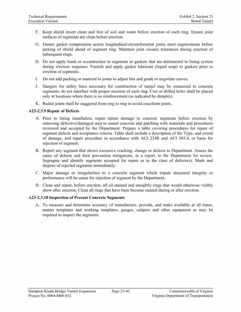
Technical Requirements Exhibit 2, Section 23 Execution Version Bored Tunnel
Hampton Roads Bridge-Tunnel Expansion Page 23-40 Commonwealth of Virginia Project No. 0064-M06-032 Virginia Department of Transportation
F. Keep shield invert clean and free of soil and water before erection of each ring. Ensure joint surfaces of segments are clean before erection.
G. Ensure gasket compression across longitudinal/circumferential joints meet requirements before jacking of shield ahead of segment ring. Maintain joint closure tolerances during erection of subsequent rings.
H. Do not apply loads or eccentricities to segments or gaskets that are detrimental to lining system during erection sequence. Furnish and apply gasket lubricant (liquid soap) to gaskets prior to erection of segments.
I. Do not add packing or material to joints to adjust line and grade or negotiate curves.
J. Hangers for utility lines necessary for construction of tunnel may be connected to concrete segments; do not interfere with proper erection of each ring. Cast or drilled holes shall be placed only at locations where there is no reinforcement (as indicated by dimples).
K. Radial joints shall be staggered from ring to ring to avoid cruciform joints.
A23-2.3.9 Repair of Defects
A. Prior to lining installation, repair minor damage to concrete segments before erection by removing defective/damaged area to sound concrete and patching with materials and procedures reviewed and accepted by the Department. Prepare a table covering procedures for repair of segment defects and acceptance criteria. Table shall include a description of the Type, and extent of damage, and repair procedure in accordance with ACI 224R and ACI 503.4, or basis for rejection of segment.
B. Report any segment that shows excessive cracking, change or defects to Department. Assess the cause of defects and their prevention mitigations, in a report, to the Department for review. Segregate and identify segments accepted for repair as to the class of defects(s). Mark and dispose of rejected segments immediately.
C. Major damage or irregularities to a concrete segment which impair structural integrity or performance will be cause for rejection of segment by the Department.
D. Clean and repair, before erection, all oil stained and unsightly rings that would otherwise visibly show after erection. Clean all rings that have been become stained during or after erection.
A23-2.3.10 Inspection of Precast Concrete Segments
A. To measure and determine accuracy of manufacture, provide, and make available at all times, master templates and working templates, gauges, calipers and other equipment as may be required to inspect the segments.

Technical Requirements Exhibit 2, Section 23 Execution Version Bored Tunnel
Hampton Roads Bridge-Tunnel Expansion Page 23-41 Commonwealth of Virginia Project No. 0064-M06-032 Virginia Department of Transportation
Appendix A23-3 – Tunnel Boring Machine Data Acquisition and Monitoring
A23-3.1 Data Monitoring
A. The tunneling process shall be monitored and documented in an adequate and state-of-the-art way to support a safe, controlled, and undisturbed tunneling operation.
1. The Design-Builder shall supply and maintain a tunneling monitoring and documentation system throughout the Project. It shall consist of the software, hardware and the relevant connections as described below. The Department shall have full access to the Design-Builder’s software with all functions.
2. The Department may purchase and maintain throughout the project an independent TBM monitoring and documentation system. This independent system is not part of the Design-Builder’s delivery. It will consist of the software, hardware and the relevant connections as described below. If desired by the Design-Builder, and subject to approval by the Department, the Design-Builder may have access to the independent monitoring software.
3. The Design-Builder shall make available, maintain, and keep permanently operational the necessary LAN to allow on-site access and remote access, as specified below:
a. The Design-Builder shall allow the installation of one data-acquisition-box on each TBM, more specific within the TBM operator’s cabin, including direct connections of the data-acquisition-box to the TBM PLC network and a network giving access to the internet for delivery of the TBM data to the independent software server on the surface. The Design-Builder shall provide a protected power supply for the installed data-acquisition-box(es).
b. The Design-Builder shall provide the capability for real-time data transfer from the data-acquisition box through the tunnel via data cable to the independent software server on the surface.
c. The Design-Builder shall support the supplier of the independent software during installation and setup for start of TBM excavation. The Design-Builder shall not withhold any information, necessary for the successful setup of the software.
4. The independent software monitoring system does not relieve the Design-Builder from its responsibility to provide a separate data collection and management system for real-time monitoring and recording of TBM operations for his own use and as described in A23-1.3.
A23-3.2 Definitions
For these Technical Requirements, the following definitions shall apply in this section:
A23-3.2.1 Software
A. Computer system to implement the TBM tunnelling monitoring and documenting tasks as described in this appendix. The software includes, but is not limited to, the data base software, database management system, front-ends, interfaces and back-up utilities.
A23-3.2.1.2 Hardware
A. Describes the data-acquisition-box and the data-server, on which the software is installed. The data-server is connected to LAN and Internet. The data-acquisition-box is connected to the TBM PLC network and to the LAN and Internet.
A23-3.2.1.3 Real Time Data Transfer

Technical Requirements Exhibit 2, Section 23 Execution Version Bored Tunnel
Hampton Roads Bridge-Tunnel Expansion Page 23-42 Commonwealth of Virginia Project No. 0064-M06-032 Virginia Department of Transportation
A. Immediate and permanent data transmission of the raw sensor readings without delay or interruption. Transmission as soon as the data are generated by the installations. The Design-Builder shall not withhold any data collected by the TBM PLC from the real-time transmission to the independent data-acquisition box and the independent software. Data retrieval frequency of a full set of data shall be not larger than 1 second, not limited by the number of indicators.
A23-3.2.1.4 Data
A. None of the data, whether generated manually or automatically by the Design-Builder’s installation and equipment, as listed in the relevant section, shall be withheld from the software. The Design-Builder shall submit for acceptance, a list of items/data collected by all equipment/installations relevant for TBM tunnelling to the Department.
A23-3.2.1.5 Local Area Network (LAN)
A. The LAN is the fixed cable connection between hardware, the Department’s and his representative’s work offices and locations, the TBM, and the access points for the tunnelling management to integrate the required data and to access the internet.
A23-3.2.1.6 On-site Access
A. All connections to the software via LAN shall have a transmission speed not less than 1 Gbit/s.
A23-3.2.1.7 Remote Access
A. There shall be uninterrupted access to the software by Internet broadband. Connection shall permit for unlimited maximum licensed users (expected are up to 200), parallel and simultaneously. Access will be controlled, secured and encrypted (for example virtual private network, VPN).
A23-3.2.1.8 Time Stamp
A. Time allocation for each set of data, set to indicate the time of measurement.
A23-3.3 General Design-Builder Software Requirements
A. The software shall permit at least the following general features as described in this section.
A23-3.3.1 Data Visualization
A. The software shall permit real-time display, in numerical form, of all data, such as trend indicators, status indicators and graphs or logic elements which are based on time, ring chainage, or tunnel meter and combinations there-of.
A23-3.3.2 Mathematical Module
A. The software shall offer a mathematical module to permit the individual creation of additional information/indicators, based on existing data. The additional information/indicators, together with all other data, shall be calculated and displayed in real time on the main software and all subsystems.
A23-3.3.3 Reporting
A. The software shall permit the individual user to design reports within the software. The user shall be able to organise individually, the timing and distribution of reports, as well as the visibility of reports according to the individual user’s role.
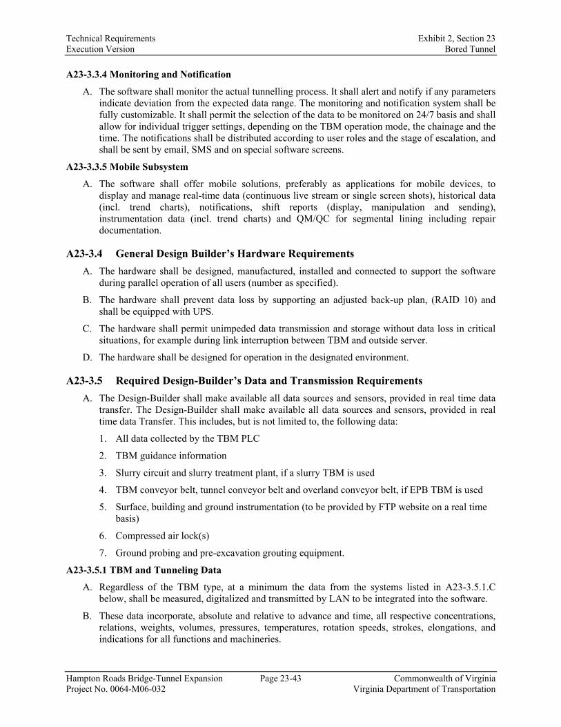
Technical Requirements Exhibit 2, Section 23 Execution Version Bored Tunnel
Hampton Roads Bridge-Tunnel Expansion Page 23-43 Commonwealth of Virginia Project No. 0064-M06-032 Virginia Department of Transportation
A23-3.3.4 Monitoring and Notification
A. The software shall monitor the actual tunnelling process. It shall alert and notify if any parameters indicate deviation from the expected data range. The monitoring and notification system shall be fully customizable. It shall permit the selection of the data to be monitored on 24/7 basis and shall allow for individual trigger settings, depending on the TBM operation mode, the chainage and the time. The notifications shall be distributed according to user roles and the stage of escalation, and shall be sent by email, SMS and on special software screens.
A23-3.3.5 Mobile Subsystem
A. The software shall offer mobile solutions, preferably as applications for mobile devices, to display and manage real-time data (continuous live stream or single screen shots), historical data (incl. trend charts), notifications, shift reports (display, manipulation and sending), instrumentation data (incl. trend charts) and QM/QC for segmental lining including repair documentation.
A23-3.4 General Design Builder’s Hardware Requirements
A. The hardware shall be designed, manufactured, installed and connected to support the software during parallel operation of all users (number as specified).
B. The hardware shall prevent data loss by supporting an adjusted back-up plan, (RAID 10) and shall be equipped with UPS.
C. The hardware shall permit unimpeded data transmission and storage without data loss in critical situations, for example during link interruption between TBM and outside server.
D. The hardware shall be designed for operation in the designated environment.
A23-3.5 Required Design-Builder’s Data and Transmission Requirements
A. The Design-Builder shall make available all data sources and sensors, provided in real time data transfer. The Design-Builder shall make available all data sources and sensors, provided in real time data Transfer. This includes, but is not limited to, the following data:
1. All data collected by the TBM PLC
2. TBM guidance information
3. Slurry circuit and slurry treatment plant, if a slurry TBM is used
4. TBM conveyor belt, tunnel conveyor belt and overland conveyor belt, if EPB TBM is used
5. Surface, building and ground instrumentation (to be provided by FTP website on a real time basis)
6. Compressed air lock(s)
7. Ground probing and pre-excavation grouting equipment.
A23-3.5.1 TBM and Tunneling Data
A. Regardless of the TBM type, at a minimum the data from the systems listed in A23-3.5.1.C below, shall be measured, digitalized and transmitted by LAN to be integrated into the software.
B. These data incorporate, absolute and relative to advance and time, all respective concentrations, relations, weights, volumes, pressures, temperatures, rotation speeds, strokes, elongations, and indications for all functions and machineries.

Technical Requirements Exhibit 2, Section 23 Execution Version Bored Tunnel
Hampton Roads Bridge-Tunnel Expansion Page 23-44 Commonwealth of Virginia Project No. 0064-M06-032 Virginia Department of Transportation
C. These requirements apply to the following tunnelling systems:
1. Excavation equipment machines and interrelated parts.
2. Material handling systems from the working chamber to ground surface, including separation plant.
3. Sealing systems.
4. TBM and back-up.
5. Thrust and steering systems.
6. TBM and tunnel guidance data.
7. Tunnel lining installation, including type and position, clearance inside shield tail before and after installation.
8. Temporary and permanent backfilling of tunnel lining.
9. All consumption materials.
10. Safety including gas monitoring, ventilation and breathable air components.
11. Ground probing and prediction systems.
12. Ground water management and discharge.
13. Cutterhead tool wear and cutterhead structure wear indicators.
A23-3.5.2 Settlement Measurements/Geo-Monitoring
A. According to the specification in the relevant section the manually or automatically acquired data shall be made available by the Design-Builder in a structured form to be integrated into the software. If the Department elects to purchase an independent monitoring software, the Design-Builder shall provide and install all necessary provisions for a transfer using FTP sites for this software. Automatic readings shall be available in real time. Manual readings shall be integrated into the database no later than 6 hours after measurement. The measurement system and software integration plan shall be submitted by the Design-Builder for acceptance by the Department, according to the submittal schedule in the relevant section.
The Department independent software monitoring system does not relieve the Design-Builder from its responsibility to provide a separate data collection and management system for real-time monitoring and recording of geotechnical instrumentation readings.
A23-3.5.3 Shift reports
A. According to the specification in the relevant section of this document the data from the shift reports shall be integrated into the Design-Builder software. Automatic readings shall be available in real time. Manual readings shall be integrated into the data base not later than 2 hours after end of shift. The reporting content, system and software integration plan must be submitted by the Design-Builder for acceptance by the Department, according to the submittal schedule in the relevant section.
A23-3.5.4 Quality Management Tunnel Lining
A. According to the specification in the relevant section of this document the data from the QM/QC of the tunnel lining shall be integrated into the Design-Builder’s software. This shall include all production data of the pre-fabricated lining elements supplied with electronically readable labels, such as bar codes. Data of the installation process, the position and possible damages and repair works shall be integrated into the software. Automatic readings shall be available in real time.

Technical Requirements Exhibit 2, Section 23 Execution Version Bored Tunnel
Hampton Roads Bridge-Tunnel Expansion Page 23-45 Commonwealth of Virginia Project No. 0064-M06-032 Virginia Department of Transportation
Manual readings shall be integrated into the data base not later than 4 hours after end of shift. The data integration plan for this requirement shall be submitted by the Design-Builder for acceptance by the Department, according to the submittal schedule in the relevant section.
A23-3.5.5 Air Quality – Tunnel
A. According to the relevant section of this document data of the air quality shall be collected in real time and monitored. Trigger levels shall be implemented for all individual sensor types to give alerts and warnings by immediate notification when the specified pollution levels are reached (see relevant section). The Design-Builder software shall send out the alarms as well as pass the information directly to the TBM operator. Data, as well as the receipts of confirmation of warning, shall be recorded and stored. The data integration plan for this requirement shall be submitted by the Design-Builder for acceptance by the Department, according to the submittal schedule in the relevant section.
A23-3.7 Data Integrity and Consistency
A. The Design-Builder shall ensure data integrity in every Project phase.
B. The Design-Builder shall ensure that all provided data is consistent and accurate. All data shall be non-contradictory to the Project context.
C. The Design-Builder shall inform the Department immediately and in writing about possible failure to fulfil a) and b).
D. In case of data transfer failure, the Design-Builder shall re-establish the data transfer within 6 hours. The Design-Builder shall undertake all efforts as reasonably possible, to make available the missing data for enclosure into the software.

Technical Requirements Exhibit 2, Section 24 Execution Version Geotechnical – Island and Tunnels
Hampton Roads Bridge-Tunnel Expansion Page 24-1 Commonwealth of Virginia Project No. 0064-M06-032 Virginia Department of Transportation
SECTION 24. GEOTECHNICAL – ISLANDS AND TUNNELS
24.1. Scope A. The geotechnical aspects of the Work (i.e., geotechnical work) pertaining to island expansions,
tunnels, and below-grade tunnel approach structures shall be investigated, designed, documented, constructed, inspected, and monitored pursuant to this Technical Requirement. Refer to Technical Requirement 15 pertaining to roadways, bridges, and landside structures.
B. The exact scope and nature of the geotechnical work is dependent upon the Design-Builder’s approach to complete the work. Aspects of the geotechnical work for island expansions, tunnels, and below-grade tunnel approach structures are anticipated to include the following:
1. Expansion of the existing islands (i.e., to enable construction of new tunnels, tunnel approach structures, and ancillary facilities).
2. Creation of engineered fill berms to enable bored tunnel construction in offshore areas where ground cover along the proposed tunnel alignment is otherwise insufficient.
3. Foundations for structures and appurtenances, including but not limited to, tunnels, below-grade tunnel approach structures, ventilation buildings, and other tunnel ancillary facilities.
4. Retaining walls (i.e., for below-grade tunnel approach structures).
C. The Design-Builder shall consider all project geotechnical information including, but not limited to, the following reports:
1. GBR.
2. GDRs comprised of the following:
a. GDR – Islands.
b. GDR – Marine.
D. Each of the above aspects of the Work requires the following items, the technical requirements for which are also provided herein:
1. Geotechnical investigations.
2. Seismic design.
3. Excavations (i.e., for below-grade tunnel approach structures, ventilation buildings, and other tunnel ancillary facilities).
4. Dewatering systems.
5. Slope design.
6. Ground movement analysis, damage risk assessment, protective measures, and repairs.
7. Ground improvement (i.e., to reduce compressibility, increase strength. or decrease permeability).
8. Geotechnical instrumentation and monitoring.
9. Pre- and post-construction condition inspections.

Technical Requirements Exhibit 2, Section 24 Execution Version Geotechnical – Island and Tunnels
Hampton Roads Bridge-Tunnel Expansion Page 24-2 Commonwealth of Virginia Project No. 0064-M06-032 Virginia Department of Transportation
24.2. References A. Refer to Technical Requirement 15, Section 15.2.
B. FHWA NH1-10-034 Technical Manual for the Design and Construction of Road Tunnels – Civil Elements.
C. FHWA-HIF-15-005 TOMIE Manual.
D. FHWA-HIF-15-006 Specifications for National Tunnel Inventory.
24.3. Requirements
24.3.1. General Requirements
A. Key Personnel: Refer to Technical Requirement 15, Section 15.3.1.A.
24.3.2. Geotechnical Investigations
A. The Design-Builder is exclusively responsible for the adequacy of the subsurface investigation program with respect to the Design-Builder’s proposed design and construction means and methods for the geotechnical work, including safety precautions and programs. The subsurface data included in Reference Information are provided for the Design-Builder’s information in accordance with Part 5, Section 102.04.
B. The Design-Builder shall develop a GEP to supplement information provided in the GDRs. Additional explorations shall be performed, as determined necessary by the Design-Builder and to meet the minimum requirements of the Work. The GEP shall meet or exceed the most stringent requirements outlined in the following:
1. VDOT MOI for Materials Division, Chapter III Geotechnical Engineering, Section 303.
2. AASHTO LRFD Bridge Design Specifications, Article 10.4.
3. AASHTO LRFD Road Tunnel Design and Construction Guide Specifications, First Edition (2017).
4. VDOT Road and Bridge Specifications, Section 700.05 (c).
C. As discussed in the GBR and required in Technical Requirement 23, a geotechnical investigation shall be performed to establish the top and bottom of the soft clay and organic layers within the alluvial marine sediment strata (sub-layers Qf and Qo, respectively) that were defined and baselined in the GBR. The investigation shall consist of soundings (e.g., borings, CPT probes) performed at a maximum spacing of 50 feet along the tunnel centerline(s), where the proposed tunnel alignment will pass though these layers on the GBR baseline subsurface profile.
D. Refer to Technical Requirement 15, Section 15.3.2 for additional requirements.
24.3.3. Geotechnical Analysis, Design, and Reporting
A. Geotechnical Analyses
1. Geotechnical analyses shall meet the requirements outlined in the following:
a. VDOT MOI for Materials Division, Chapter III, Section 305.

Technical Requirements Exhibit 2, Section 24 Execution Version Geotechnical – Island and Tunnels
Hampton Roads Bridge-Tunnel Expansion Page 24-3 Commonwealth of Virginia Project No. 0064-M06-032 Virginia Department of Transportation
b. AASHTO LRFD Bridge Design Specifications, including VDOT Modifications (VDOT IIM-S&B-80).
c. AASHTO LRFD Road Tunnel Design and Construction Guide Specifications, First Edition (2017).
2. Geotechnical analyses shall be performed under the direct supervision of the Geotechnical Manager.
3. Geotechnical analyses shall be performed using geotechnical software that is widely accepted within the industry for the intended application.
B. Geotechnical Design Parameters: Refer to Technical Requirement 15, Section 15.3.3.B.
C. Geotechnical Engineering Reports
1. GERs shall address all geotechnical work, including but not limited to the following:
a. Island expansions and offshore engineered fill berms.
b. Each major and minor structure (see below for definitions).
i. Major structures for VDOT projects include tunnels, retaining walls greater than 10 feet high, and structures to be supported on deep foundations.
ii. Minor structures for VDOT projects are supported on shallow foundations and include retaining walls less than ten 10 feet high.
2. Refer to Technical Requirement 15, Section 15.3.3 for additional requirements.
24.3.4. Seismic Design Considerations
A. The Design-Builder shall account for seismic loadings in accordance with AASHTO LRFD Tunnel Design and Construction Specifications for tunnel structures and below-grade tunnel approach structures.
B. With reference to AASHTO LRFD, the importance category of the tunnel and below-grade tunnel approach structures is defined as “Critical”.
C. The Design-Builder shall demonstrate that the predicted seismic-induced movement of the tunnel can be accommodated by the design in accordance with the Technical Requirements.
D. The Design-Builder shall evaluate liquefaction susceptibility of existing islands, proposed island expansions, and proposed offshore engineered fill berms (if applicable) using cyclic resistance and cyclic stress ratios estimated from in-situ SPT and/or CPT data (R.B. Seed or I.M. Idriss and R.W. Boulanger methods). Liquefaction-induced settlements may also be estimated using the in-situ SPT and/or CPT data (Ishihara and Yoshimi Method). Liquefaction assessments for other work along the project corridor shall be performed in accordance with AASHTO LRFD.
24.3.5. Island Expansions
A. Scope
1. This section describes the technical requirements for the expansion of islands to accommodate the Work, including tunnels, tunnel approach structures, and ancillary facilities.
2. Refer to Technical Requirement 16 for technical requirements related to protection of the expanded islands against scour, ship grounding, ship anchors, and other marine hazards.

Technical Requirements Exhibit 2, Section 24 Execution Version Geotechnical – Island and Tunnels
Hampton Roads Bridge-Tunnel Expansion Page 24-4 Commonwealth of Virginia Project No. 0064-M06-032 Virginia Department of Transportation
B. Design, Analysis and Design Submittals
1. Drawings. The Design-Builder shall provide drawings of the proposed island expansions to the Department for review and authorization. The drawings shall be signed and sealed by the Geotechnical Manager, and shall include:
a. Plans showing the general arrangement of the new land mass, including the locations of tunnels, buildings, retaining walls, paved areas, and other relevant features. The plans shall clearly show the locations of geotechnical explorations for reference.
b. Representative geotechnical profiles, including cross-sections of the island expansion shoreline protection. The profiles shall indicate the island expansion materials and extend from the proposed ground surface to firm, non-compressible soil at depth, below which settlement will not occur.
c. Required engineering properties of the reclamation fill (i.e., grain size distributions, density, and other properties identified by the Technical Requirements and authorized plans and required engineering properties of any geotextiles, coordinated with settlement and slope stability analyses. The Geotechnical Manager shall establish thresholds for tolerances for pockets of non-compliant material within the expanded islands. Acceptable thicknesses of non-compliant material for a single incident and the total accumulated thickness of non-compliant material pockets in the same profile shall be established.
d. Details of any ground improvement, surcharge fill, or drainage system (i.e., wick drains) used to reduce or expedite consolidation settlement.
e. Construction sequence of the proposed island expansions.
f. Work to protect existing islands, structures, utilities, slopes, and other existing features during the proposed construction.
2. Specifications
a. The Design-Builder shall provide specifications, signed and sealed by the Geotechnical Manager, for the proposed island expansions to the Department for review and authorization. At a minimum, the specifications shall address and be consistent with the topics covered in the Technical Requirements. The Design-Builder shall bring to the attention of the Department any proposed deviation from the Technical Requirements.
3. Settlement Analysis
a. In advance of submitting its full settlement analysis, the Design-Builder shall submit its design approach for performing the settlement analysis to the Department for review and acceptance. The design approach submittal shall describe the proposed analysis methods, including the name and description of any computer software modeling programs to be used. The software shall be industry-recognized software.
b. The settlement analysis shall consider elastic settlement, primary (consolidation) settlement, and secondary compression.
c. The settlement analysis shall account for vertical and radial drainage (i.e., anisotropic permeability) as well as reduction in permeability that occurs with compression of the soil and changes in vertical stress that occur beyond the actual limits of loading.

Technical Requirements Exhibit 2, Section 24 Execution Version Geotechnical – Island and Tunnels
Hampton Roads Bridge-Tunnel Expansion Page 24-5 Commonwealth of Virginia Project No. 0064-M06-032 Virginia Department of Transportation
d. The Design-Builder shall perform damage risk assessments for existing structures in accordance with Section 24.3.18.
e. Settlement Limits. Refer to this Technical Requirement, Section 24.3.18 for settlement limits.
4. Slope Stability Analyses. The Design-Builder shall perform slope stability analysis for temporary and permanent conditions in accordance with Section 24.3.17.
5. Documentation of Analyses in GERs
a. Refer to this Technical Requirement, Section 24.3.3.
b. The Design-Builder shall provide a detailed summary of all geotechnical parameters used in the analyses and their supporting raw data (borehole logs, laboratory test results, and their interpretations for use in the analyses).
c. The Design-Builder shall provide design computations for developing the fill/surcharge schedule considering slope stability (i.e., ensure the placement of fill for any lift does not result in short-term instability in the undrained condition). The fill/surcharge schedule shall, at a minimum, include maximum lift heights and target pore pressures for preventing slope failures. Document any assumed strength gains associated with compression from placement of preceding lifts (with justification based on laboratory testing or other method as accepted by the Department).
d. The Design-Builder shall provide predicted settlement contour plans for the expanded islands. Separate plans shall be provided for predicted settlement at the end of primary (consolidation) settlement and predicted settlement at the end of secondary compression. The Design-Builder shall demonstrate that the proposed construction meets the settlement limits provided in this Technical Requirement, Section 24.3.18.
e. The Design-Builder shall provide an Instrumentation and Monitoring Plan that meets the requirements of this Technical Requirement, Section 24.3.20. The plan shall detail the procedures, equipment, methods, and materials planned for monitoring and documenting settlement, lateral movement, and pore water pressure increase/dissipation resulting from the proposed island expansions. The plan shall include threshold levels for each instrument, fully coordinated with the ground movement analysis.
C. Other Submittals
1. Reclamation Plan. The Design-Builder shall submit the Reclamation Plan to the Department for acceptance prior to start of fill operations. The plan shall contain the following:
a. Copies of all permits and certifications (the Design-Builder is responsible to obtain all required permits and certifications from agencies having jurisdiction).
b. Proposed equipment and method for removing or placing each material type. Provide the following information for each vessel to be used: displacement, draft, length. and beam; type and capacity of dredge; crane details; description of hydrographic survey equipment, positioning system, and display system for dredging and placement of fill; nominal crew size and live-aboard capacity; size and types of anchors; size and type of jack-up barge legs; proof of insurance and proof of pollution insurance; indicated horsepower, shaft horsepower, and bollard pull force for towboats.

Technical Requirements Exhibit 2, Section 24 Execution Version Geotechnical – Island and Tunnels
Hampton Roads Bridge-Tunnel Expansion Page 24-6 Commonwealth of Virginia Project No. 0064-M06-032 Virginia Department of Transportation
c. Navigational Channel MOT Plan.
d. Identification of key personnel conducting marine operations and records substantiating their performance of similar work in the past 5 years.
e. Overwater operations safety plan, including criteria and procedures for responding to changes in weather.
f. Approximate schedule for the Work associated with the proposed island expansions.
g. Acceptance areas, and order and sequencing of the Work associated with proposed island expansions, including but not limited to ground improvement, dredging and fill placement, installation of wick drains or other vertical drainage elements, and placement and removal of surcharge fills,
h. Mooring and anchor patterns and locations with respect to fixed structures for all vessels, including proposed anchor, spud pile, and jack-up barge locations,
i. All applicable QC procedures including, but not limited to the following: surveys, inspections, sampling and testing, instrumentation and monitoring, and reporting. The Design-Builder and the Department shall agree on the reporting procedures and formats.
j. Qualifications and equipment calibration certificates for the testing laboratory performing the required tests.
k. List of hydrographic surveying equipment including type, brand, frequency, and precision. Provide calibration certificates of all equipment to be used. Equipment with expired calibration certificates shall not be used.
l. Layout and shop drawings of any dikes, drains, silt fences, berm, and other measures to control erosion and siltation of the borrow materials, approved by the Geotechnical Manager.
m. Material separation plan (i.e., separation of suitable from unsuitable material).
n. Details of the Design-Builder’s intended corrective measures, should any environmental hazards be detected.
o. Location of materials supplies and documentation of supplier’s willingness and capacity to provide the needed quantities of materials for the proposed design.
p. Location of material disposal areas.
q. Methodology for densifying or otherwise improving the reclamation fill or subsurface strata if required to meet the Technical Requirements (i.e., settlement criteria as stated in this Technical Requirement, Section 24.3.18) and achieve the engineering properties as stated in the authorized plans.
r. Demolition and island protection plan, including sequencing of the Work as well as layout and shop drawings of all demolition and island protection features, approved by the Geotechnical Manager.
2. Borrow Source Report. The Design-Builder shall submit a report to the Department pertaining to the borrow source locations prior to the start of fill operations. The report shall

Technical Requirements Exhibit 2, Section 24 Execution Version Geotechnical – Island and Tunnels
Hampton Roads Bridge-Tunnel Expansion Page 24-7 Commonwealth of Virginia Project No. 0064-M06-032 Virginia Department of Transportation
include the borrow source locations, representative material gradations, and moisture density curves for each material proposed for use; laboratory test results; and quantity of available material from each source. Depth of dredge shall be included if the material is being sourced from an offshore location. The Geotechnical Manager shall certify that the borrow source is in accordance with the Technical Requirements and the authorized plans.
3. Stone Materials
a. Stone Sources. The Design-Builder shall submit records of all proposed stone sources, approved by the Geotechnical Manager. The submittal shall include:
i. Areas and lifts of the quarry or pit to be worked.
ii. The specific geological stratum or strata to be utilized.
iii. Available laboratory testing records.
iv. Bulk specific gravity range.
v. Completed projects constructed of the same stone to be furnished.
For the projects completed with stone from the same source, the Design-Builder shall provide detailed descriptions of the size of stone produced, quantity of stone produced, and amount of stone that was rejected. The proposed stone sources shall be designated at least 60 days in advance of using that source.
b. SMC Plan: The Design-Builder shall submit a written SMC plan, approved by the Geotechnical Manager, describing the means and methods to be used for producing, handling, transporting, placing, testing, and inspecting stone materials. The SMC Plan shall also include the anticipated placement and delivery rates for each size of stone. Written procedures shall be included for guiding and instructing the Design-Builder’s inspectors and other employees in the techniques and criteria to be used for examining stone for acceptability and for the proper production gradation, handling, transporting, and placement of stone. Procedures shall be described for tracing armor stones used in conducting gradation tests and for reporting the performance and results of the tests on QC reports. Procedures shall be described for documenting that furnished stone complies with the applicable quarrying period and curing restrictions, if any.
The SMC Plan shall also include a sample of a daily SMC QC inspection report, which shall be used during stone material production. The SMC plan shall be submitted for acceptance not less than 30 calendar days in advance of the date stone materials are to be shipped from the source. Acceptance of the SMC plan by the Department shall not be provided until after the Design-Builder has produced satisfactory demonstration stockpiles, including laboratory testing results.
c. Demonstration Stockpiles. Following submittal of source selection and the SMC plan, the Design-Builder shall select the demonstration stockpile stones for review of the Department. The Design-Builder shall accompany the Department or its designated representative during the evaluation of the demonstration stockpiles. The stockpile shall contain at least 10 stones representing acceptable quality and weight within the specified size range for each type of stone to be furnished. The supplier shall produce a histogram of the initial stockpiles for each type of stone to be furnished, in accordance with ASTM D5519 (Method A) that shows the spectrum of sizes and weights for each class in the

Technical Requirements Exhibit 2, Section 24 Execution Version Geotechnical – Island and Tunnels
Hampton Roads Bridge-Tunnel Expansion Page 24-8 Commonwealth of Virginia Project No. 0064-M06-032 Virginia Department of Transportation
stockpile. The histogram shall be repeated at 100,000-ton frequencies for each type of stone to be furnished. The stones placed in the demonstration stockpiles shall be representative of the overall quality of materials in the source and representative of the stone quality to be furnished to the Project. The stockpiles shall be located at the source of the stone and be laid out in windrow fashion. The Design-Builder shall arrange to have individual stones to be free from any dust or mud covering the faces and turned as necessary to accommodate the Department’s evaluation. The Department will mark rejected stones with a “red X.” If greater than 20% of the stones within a demonstration stockpile are found to be unacceptable, the entire stockpile may be rejected by the Department and a replacement stockpile created for re-evaluation. The set-aside samples selected and marked during the inspection of the demonstration stockpile shall remain unchanged at the source until all other required material of the size range represented by the stockpile has been shipped from the source. Stones having each type of unacceptable features shall also be set aside at the quarry as examples of unacceptable stone that shall not be shipped.
4. Geotextiles:
a. The Design-Builder shall submit the manufacturer’s data sheet detailing the guaranteed physical properties of the geotextile material and shall confirm these properties are consistent with the design requirements as indicated on the authorized plans.
b. The Design-Builder shall describe proposed installation procedure for the geotextile, in accordance with this Technical Requirement.
c. The Design-Builder shall confirm the geotextile material is on Approved List #63 for the intended use. For high-strength geosynthetics and geogrids, manufacturer sample data shall be submitted for the lot that was delivered to the project in accordance with VDOT’s latest SP.
5. Daily Reports
a. Daily Reclamation Report: The Design-Builder shall provide an updated daily log of vessel activity, including locations where each vessel was deployed on each day at the project location, the volumes of each type of material dredged or placed at each location, and other construction activities related to island expansions.
b. The Design-Builder shall provide daily SMC QC inspection reports.
6. Pre-construction, progress, and post-construction surveys (hydrographic and topographic) shall be submitted in accordance with Technical Requirement 8 and with the authorized reclamation plan.
7. Results of material sampling and testing. Test results shall be issued to the Department daily. The Geotechnical Construction Engineer or his qualified inspectors shall provide written certification to the QAM that the test results are in compliance with the Technical Requirements and authorized plans, and shall advise the Department of any discrepancies.
8. Instrumentation and monitoring results as per this Technical Requirement, Section 24.3.20.
9. As-built report for each island expansion, including the results of surveys and inspection, sampling, testing, and monitoring. The Geotechnical Manager shall provide certification that

Technical Requirements Exhibit 2, Section 24 Execution Version Geotechnical – Island and Tunnels
Hampton Roads Bridge-Tunnel Expansion Page 24-9 Commonwealth of Virginia Project No. 0064-M06-032 Virginia Department of Transportation
the island expansions (reclamation) meet the Technical Requirements and authorized plans with reference to the inspection, sampling, testing, and monitoring.
D. Material Requirements
1. Fill Materials
a. Fill materials shall include suitable dredged fill material, suitable fill material from upland sources, and rock fill. All fill materials shall be provided by the Design-Builder.
b. Suitable fill shall be limited to material classified as GW, GP, SW, SP, GW-GM, GP-GM, SW-SM, and SP-SM per ASTM D2487, unless otherwise accepted by the Department.
c. Unsuitable Material is defined as material that meets one or more of the following criteria: classified as CH, MH, OH, and OL in accordance with the Unified Soil Classification System; contains more than 5% by weight organic matter; exhibits a swell greater than 5% as determined from the CBR test using VTM-8; exhibits strength, consolidation, durability of rock, or any other characteristics that are deemed unsuitable by the Geotechnical Manager or are denoted as unsuitable in the Contract Documents for use in the Work. All materials within the uppermost 3 feet of a pavement subgrade that exhibit a soaked CBR value less than 10 shall also be considered unsuitable.
The anticipated locations and methods of treatment for unsuitable materials identified by the Geotechnical Manager shall be shown on the design plans and cross-sections. Saturated, very dry and/or loose, or very soft coarse- and fine-grained soils that exhibit excessive pumping, weaving, or rutting under the weight of construction equipment are also considered unsuitable unless they can be moisture conditioned through either mechanical or chemical means to an acceptable moisture content that allows adequate compaction to meet project specifications, and classification testing indicates they are not otherwise unsuitable. Topsoil, root mat, organic debris, and peat shall be considered unsuitable material. All unsuitable material shall be disposed of and/or treated as discussed in Part 5 - Division I Amendments, Section 106.04 at no additional cost to the Department. Topsoil or other organic soils are also considered unsuitable for use in embankment fill, other than as a cover for slopes for the purpose of establishing vegetative cover. When used as cover for slopes, the thickness of topsoil shall not exceed 12 inches.
d. Fill material shall be composed of hard, sound particles having a specific gravity of solids of not less than 2.6 and a maximum soundness loss of 15% when tested in accordance with AASHTO T103 (freeze and thaw, 100 cycles) or a maximum soundness loss of 30% when tested in accordance with AASHTO T104 (magnesium sulphate, five cycles).
e. Fill material shall be essentially free from thin, flat, and elongated pieces (i.e., not more than 30% by mass of particles retained on 3/8-inch sieve having a maximum to minimum dimensional ratio greater than 5, as determined in accordance with ASTM D4791).
f. The fill shall not contain cohesive soils such as marine mud or swelling clays; peat, vegetation, timber, organic material, or other deleterious materials; material that is soluble or perishable in seawater; hazardous or toxic material, or material susceptible to combustion; metal, rubber, plastic, or synthetic material; or gypsum.

Technical Requirements Exhibit 2, Section 24 Execution Version Geotechnical – Island and Tunnels
Hampton Roads Bridge-Tunnel Expansion Page 24-10 Commonwealth of Virginia Project No. 0064-M06-032 Virginia Department of Transportation
2. Stone
a. All stone to be used in the Work (including rip-rap, filter, and armor stone) and bedding material shall conform to the VDOT Road and Bridge Specifications, Section 204.02(b).
b. Acceptability of stone materials shall be based on visual inspections, evaluation of service records, and applicable laboratory test results. All materials shall meet the minimum quality requirements listed in Table 24.3.5-1, based on field examination and applicable laboratory testing.
c. The maximum aspect ratio (i.e., greatest dimension: least dimension, when measured across three mutually perpendicular axes) shall not be greater than 3:1 for stones used as armor stone, and not greater than 5:1 for filter and bedding stones. Up to 10% by weight of stones may exceed these maximum aspect ratio requirements.
d. Replacement protection stone for existing slopes, where the existing protection stone is removed by the Design-Builder, shall be sized in accordance with Technical Requirement 16.
Table 24.3.5-1: Criteria for Stone Quality
Test1 Text Method Acceptance Criteria
Specific Gravity ASTM D6473 >2.5
Absorption ASTM D6473 < 3%
Los Angeles Abrasion ASTM C535 < 20% loss after 500 revolutions
Freeze Thaw2 ASTM D5312 < 2% loss after 35 cycles
Wetting-Drying2 ASTM D5313 < 2% loss after 80 cycles
Petrographic Examination ASTM C295 No deleterious3 materials allowed
Field Examination ASTM D4992 No deleterious3 materials allowed
Sodium Sulphate Soundness or Magnesium Sulphate Soundness
ASTM D5240 < 5% loss after 5 cycles
Notes: 1 See Paragraph E.2 and Table 24.3.5-2 below for applicability of tests. 2The Design-Builder shall ensure that the selected laboratory is Department-accepted for the required capacity/equipment to allow for testing of large sample sizes. The minimum testing slab dimension shall be 13 inches by 15 inches by 2.5 inches for ASTM D5312 and D5313, and shall be cut perpendicular to the bedding planes of the stone. 3Deleterious material is defined as a zone of impurities or weakness, including seams, cracks, or other structural defects; or material that is soluble in seawater or erodible in a marine environment that could be detrimental to the long-term performance of the stone for the intended application.

Technical Requirements Exhibit 2, Section 24 Execution Version Geotechnical – Island and Tunnels
Hampton Roads Bridge-Tunnel Expansion Page 24-11 Commonwealth of Virginia Project No. 0064-M06-032 Virginia Department of Transportation
3. Geotextiles
a. Geotextiles shall meet the requirements of the VDOT Road and Bridge Specifications, Section 245, and AASHTO M288.
b. Geotextile material shall be on Approved List #63 for the intended use.
c. High-strength geosynthetics and geogrids shall meet the requirements of VDOT’s latest SP.
d. Geotextiles shall be delivered to the Project in packaging that protects the rolls from degradation by ultraviolet light and other weather elements. The labeling shall clearly identify the product supplied in accordance with ASTM D4873.
e. Geotextiles shall be kept in the wrappings provided by the manufacturer until required for use in the Work.
f. The Design-Builder shall ensure the quality and the protection of the product on-site, following the manufacturer’s recommendations.
g. Geotextiles shall be protected against physical or chemical damage.
h. The rolls of geotextile shall be stored on level ground and stacked not more than five rolls high, and no other materials shall be stacked on top of the geotextiles.
4. Topsoil shall be in accordance with the VDOT Road and Bridge Specifications, Section 602.
E. Quality Control: Material sampling, laboratory testing and inspection (as Supplied)
1. Fill
a. The Design-Builder shall sample and test all materials that may be used as fill on the Project. The Geotechnical Construction Engineer and their qualified inspectors shall certify that the fill material meets the Technical Requirements and authorized plans.
b. A grain size analysis (ASTM D6913 or ASTM C136) shall be performed for each 5,000 tons of material to be used as fill for island expansion. Grain size analyses shall be used to assign an ASTM group name, providing the sample shows no plasticity. The Design-Builder shall submit daily reports with average grain size analyses for the samples collected that day.
c. Each sample collected for grain size analysis shall be visually inspected for plasticity and, in any case of doubt, Atterberg Limits testing (ASTM D4318) shall be performed.
d. Direct shear tests (ASTM D3080) and maximum and minimum dry density tests (ASTM D4253 and ASTM D4254, respectively) shall be performed for each 20,000 cubic yards of reclamation material. Direct shear tests shall be performed on specimens prepared to the design density, as per the authorized plans. Each direct shear test shall be performed at three normal loads, representing the ranges of stresses for the material(s). The Geotechnical Manager shall interpret all direct shear tests to establish the Mohr-Coulomb failure criteria and compatibility to the proposed design. The Design-Builder shall allow the Department to witness sampling of the reclamation material at the times and frequency determined by the Department.

Technical Requirements Exhibit 2, Section 24 Execution Version Geotechnical – Island and Tunnels
Hampton Roads Bridge-Tunnel Expansion Page 24-12 Commonwealth of Virginia Project No. 0064-M06-032 Virginia Department of Transportation
2. Stone
a. The Design-Builder shall perform the testing and visual inspection specified in Table 24.3.5-2. At a minimum, the required testing shall be performed once for each stone type listed and once for each quarry sourced. Protection stone that is removed from existing slopes and stockpiled for reuse shall not require stone quality testing but shall require visual inspection (i.e., for wear, cracking, breakage) and gradation testing in accordance with this section.
b. The Design-Builder shall submit copies of test results at least 60 calendar days in advance of shipment of stone to the work site, and no later than the time of inspection of the demonstration stockpile by the Department.
c. Gradation tests shall be performed for armor stone used for slope protection, tunnel protection, and scour protection. One gradation test at the quarry is required for each 20,000 tons of stone, with a minimum of one test for each rock class per quarry. Each armor stone used in gradation testing shall be marked, tracked and documented in accordance with the procedures submitted and accepted in the SMC Plan. Gradation test reports for armor stone shall include the three axis dimensions for aspect ratio measurement and the basis of individual stone weight calculations.
Gradation tests for standard VDOT sized riprap (I, II, III, and AI) will not be required. Standard VDOT sized riprap (I, II, III, and AI) will be accepted based on visual gradation in accordance with VDOT Manual of Instruction for Materials Division.
d. At least one gradation test shall be performed for each 20,000 tons of filter or bedding stone to be delivered to the Project for each specified gradation in accordance with ASTM C136.
e. The stone quality testing frequency may be increased at the direction of the Department if there are visually observed changes in the characteristics of the stone material.
f. The Design-Builder shall perform visual inspection of each proposed armor stone, both at the quarry and at the Project. The visual inspections shall check size, elongation, fractures, deterioration, and other defects to assure that handling during loading, transporting, unloading, and placement has not caused damage to the materials; and to assure the materials are placed in accordance with this Technical Requirement. Weighing or re-measurement of stones shall be performed to verify computed weights when the Department brings the size of specific stones into question.
g. The Department may elect to perform sampling, testing, and inspection in addition to that required to be performed by the Design-Builder. The Design-Builder shall provide safe access for the Department or its representatives to perform sampling, testing, and inspection. In the event the testing requires transportation of stone to an off-site location (i.e., testing laboratory), the Design-Builder shall bear the cost of handling and transporting the stone if the stone is found to be non-compliant with the Technical Requirements or authorized plans; otherwise, the cost of handling and transporting the stone shall be borne by the Department.
h. Except as allowed by gradation tolerances, any material broken, cracked, out of gradation or weight limitation, or improperly placed in the work shall be removed and replaced with satisfactory stones, and corrective action shall be taken, all at no additional expense

Technical Requirements Exhibit 2, Section 24 Execution Version Geotechnical – Island and Tunnels
Hampton Roads Bridge-Tunnel Expansion Page 24-13 Commonwealth of Virginia Project No. 0064-M06-032 Virginia Department of Transportation
to the Department. Rejected material shall be promptly removed from the Project Right of Way.
Table 24.3.5-2: Stone Sampling and Testing Requirements
Stone Type Sample Size Frequency Stone Quality Testing Visual Inspection of Demonstration
Stockpile
Armor Stone One stone 100,000 tons
All tests listed in Table 24.3.5-1 Yes
VDOT Dry Riprap Class I, II, III and AI
20 stones 100,000 tons
All tests listed in Table 24.3.5-1 Yes
Filter and Bedding Stone
2,000 pounds 100,000 tons
ASTM D6473, ASTM C535, ASTM D5240
No
3. Geotextile
a. Geotextile material shall be on Approved List #63 for the intended use.
b. For high-strength geosynthetics and geogrids, testing shall be performed for the product that was delivered to the project in accordance with VDOT’s latest SP.
F. Equipment
1. The Design-Builder shall furnish, maintain, and operate all equipment for island expansion work, including material removal, material placement, and hydrographic surveys.
G. Not Used.
H. Operation of existing islands, including traffic. The Design-Builder shall not impede access to or operation of the existing islands. Traffic through the existing tunnels shall be maintained in both directions at all times. All traffic shall be protected from construction operations throughout the Work.
I. Earthwork shall meet the requirements of VDOT Road and Bridge Specification, Section 303.
J. Settlement. It is anticipated that both the island expansion fill and underlying soils will settle. The Design-Builder shall make all necessary allowances for the effects of settlement on the proposed Work and on the existing buildings, utilities, and infrastructure. Refer to this Technical Requirement, Section 24.3.18.
K. Ground Improvement. The Design-Builder may elect to perform ground improvement of existing soils to improve the engineering properties of these soils in accordance with the authorized plans. Ground improvement shall be performed in accordance with Section 24.3.19.
L. Site Clearing
1. The Design-Builder shall be responsible for identifying, removing, transporting, and disposing of any unsuitable foundation soils (i.e., soft soils and organic soils) prior to placing reclamation material unless such soils are explicitly addressed in the authorized plans (e.g., ground improvement).
2. Trash, debris, and other miscellaneous man-made and natural objects may be encountered during dredging. Material to be expected includes, but is not limited to, the following: stones,

Technical Requirements Exhibit 2, Section 24 Execution Version Geotechnical – Island and Tunnels
Hampton Roads Bridge-Tunnel Expansion Page 24-14 Commonwealth of Virginia Project No. 0064-M06-032 Virginia Department of Transportation
tires, cables, chains, anchors, metallic debris, plastics, munitions, lumber, and tree branches. The Design-Builder shall identify, remove, transport, and dispose of such materials prior to placement of materials for island expansions.
3. All materials shall become property of the Design-Builder upon removal. All materials shall be properly disposed of in conformance with the requirements of the authorized plans at no additional cost to the Department. The Design-Builder shall be solely responsible to identify disposal areas and obtain all necessary permits for disposal.
M. Demolition and Protection of Existing Island Perimeter
1. The Design-Builder shall be responsible for removing or relocating any existing armor stone, seawalls, fencing, utilities, pavements, sidewalks, curbs, gutters, signage, or other features that interfere with the proposed island expansion.
2. Demolition and stone removal operations shall be at the Design-Builder’s risk.
3. The Design-Builder shall plan construction to minimize disturbance to the existing islands.
4. The existing island slopes shall be protected throughout construction (i.e., against scour, erosion, slope failure, and marine hazards) such that their integrity is not compromised during either normal, routine construction or during storm events arising throughout the duration of the Work. At a minimum, the Design-Builder shall provide protection from the 1% annual chance storm wave and current conditions at all times. During periods when construction may be interrupted, the Design-Builder shall provide protection of any exposed ends of construction from damage. Any damage to installed Work during periods of interruptions shall be the Design-Builder’s responsibility.
5. Existing armor stone shall be removed, stockpiled, and segregated as required for reuse or disposal. The Design-Builder shall determine the best use of the removed existing armor stone. All existing armor stone not meeting the requirements for reuse on the expanded island or on existing slopes shall become the Design-Builder’s property and disposed of off-site. The Design-Builder shall be responsible for all permits required for reuse or disposal of the existing armor stone.
6. Existing outfalls, seawalls, structures, highways, roadways, utilities, equipment, and other infrastructure, both on and leading up to the existing islands, shall be maintained and protected throughout construction unless specifically authorized otherwise by the Department.
7. The Design-Builder shall be responsible for damage to areas or items designated by the Department to be protected. All areas disturbed shall be restored to a condition equal to or better than the original conditions, and shall be graded to provide positive drainage to SWM facilities. Repairs to or replacement of areas or items damaged shall be made at the Design-Builder’s expense and to the satisfaction of the Department before acceptance of the completed Work.
N. Supply and Delivery of Reclamation Fill Material
1. Reclamation fill material shall be taken from the borrow areas, as indicated on the authorized plans, by means of dredging or by transporting from an upland source. The Design-Builder shall be responsible for identifying the fill material source and complying with the Technical

Technical Requirements Exhibit 2, Section 24 Execution Version Geotechnical – Island and Tunnels
Hampton Roads Bridge-Tunnel Expansion Page 24-15 Commonwealth of Virginia Project No. 0064-M06-032 Virginia Department of Transportation
Requirements and authorized plans. The Design-Builder shall be responsible for permits associated with using the borrow source.
2. Material shall be transported in dredges, barges, or similar in compliance with permit conditions. Truck delivery of fill material shall not be allowed.
3. Based upon the fill material source, location, and the Baseline Schedule, the Design-Builder shall select equipment of appropriate capacity to perform the work continuously. Any siltation that may occur is the Design-Builder’s responsibility to correct at no additional cost to the Department.
4. The Design-Builder shall be responsible for containment of the reclamation fill material at the dredge site, at the reclamation site, and along the transportation route between the sites. In addition, the Design-Builder shall be responsible for protecting the material (i.e., from gullying, scour, and erosion) once it is deposited on the island. Any loss of material shall be the Design-Builder’s responsibility, with no additional cost to the Department.
5. Fill types and properties shall be in accordance with the Technical Requirements and authorized plans. If the fill material does not comply with the Technical Requirements and authorized plans, the Design-Builder shall submit a remediation plan, approved by the Geotechnical Manager, for review by the Department. The remediation plan shall show that the Technical Requirements and authorized plans for the finished island will be met after completion of remediation. Remedial measures shall be at the cost of the Design-Builder. This shall include the Department’s right to reject any material or source from which the sample was taken. In such case, disposal of the unsuitable material shall be the Design-Builder’s responsibility.
6. Restoration of borrow areas shall be in accordance with federal, state, and local laws and regulations.
O. Dredging and Placing of Fill Materials
1. All necessary site clearing shall be performed prior to placing any reclamation fill materials.
2. Construction shall proceed with a minimum of interruption to the prescribed lines and grades and in accordance with the authorized plans. The Design-Builder shall furnish, set, and maintain ranges, buoys, or markers as needed to guide fill placement and to facilitate surveys and inspections. Dredging and fill placement operations shall be suspended when ranges, buoys, or markers cannot be seen.
3. The Design-Builder shall select fill placement methods that minimize loss of material and the possibility of silt/clay pocket formation within the reclamation. The Design-Builder’s construction methodology and sequence of activities shall protect the reclaimed material from losses from erosion due to wave action, currents, tidal effects, or other natural forces until Final Completion. The Design-Builder shall provide and maintain necessary bulkheads, dikes, ditches, weirs, spillways, and other construction necessary to confine and retain the fill.
4. The Design-Builder shall control the placement of fill materials in a manner than limits the turbidity of bay waters in accordance with permit conditions.
5. Segregation of reclamation materials (i.e., such that distinct bands or layers of soils with different grain sizes are created) shall not be permitted irrespective of the method of

Technical Requirements Exhibit 2, Section 24 Execution Version Geotechnical – Island and Tunnels
Hampton Roads Bridge-Tunnel Expansion Page 24-16 Commonwealth of Virginia Project No. 0064-M06-032 Virginia Department of Transportation
placement. If such segregation occurs, the Design-Builder shall make any required corrections at its own expense.
6. The Design-Builder shall remove any naturally-deposited sediment that accumulates at the base of dredged trenches or between fill placements at reclamation locations.
P. Densification of Fill
1. Island fill material shall be densified or otherwise improved to meet the requirements of the authorized plans and the minimum reclamation fill density as stated below.
2. Minimum Reclamation Fill Density. During the reclamation process, the Design-Builder shall place accepted material within the reclamation area to achieve an in-situ design density in accordance with the authorized plans, but not less than 50% of the relative density of the soil, throughout the full thickness and lateral extent of the fill. If the estimated density of the reclaimed fill is less than the in-situ design density or 50% of the relative density of the soil, as determined by the procedures outlined in this Technical Requirement, Section 24.3.5.Q, then remedial measures will be required as per Section 24.3.5.R.
3. Subgrade compaction testing and control (i.e., for subgrades of buildings and structures, roads, and parking lots located within the proposed fill) shall be as outlined in Table 24.3.5-3.
Table 24.3.5-3 Subgrade Compaction Testing and Control – Testing Frequency per Lift of Fill
Location Frequency1
Buildings and structures 1 test group for every 10 square yards
Road 1 test group for every 100 feet of road
Parking lots 1 test group for every 24 square yards
Unpaved areas 1 test group for every 40 square yards
Pipe or conduit trench 1 test group for every 150 feet
Notes: 1) One test group consists of compaction tests on each layer of fill and backfill.
Q. Quality Control: Inspection, Sampling, and Testing for Reclaimed Land (as Placed)
1. The Design-Builder is responsible for developing an inspection and testing program to demonstrate that the reclaimed land meets the Technical Requirements and authorized plans.
2. At a minimum, the Design-Builder shall perform the following inspection and testing of the reclaimed land, finished in place.
a. Pre-bored pressuremeter tests in accordance with ASTM D4719 shall be conducted on a grid with maximum 300-foot spacing between boreholes. Pressuremeter tests shall be conducted at 5-foot vertical spacing in each borehole, from a depth of 5 feet below the ground surface to a depth of 25 feet below the original seabed. SPTs shall be performed between pressuremeter tests in accordance with ASTM D1586 in all borings at maximum 5-foot intervals, and samples shall be collected using a split-barrel sampler for particle size distribution Using Sieve Analysis ((ASTM D6913) and Atterberg limits (ASTM D4318) testing.

Technical Requirements Exhibit 2, Section 24 Execution Version Geotechnical – Island and Tunnels
Hampton Roads Bridge-Tunnel Expansion Page 24-17 Commonwealth of Virginia Project No. 0064-M06-032 Virginia Department of Transportation
b. CPTs with pore water pressure measurements in accordance with ASTM D5778 shall be conducted on a grid with maximum 300-foot spacing between CPTs. Each CPT shall extend to a minimum 25 feet below the original seabed.
3. The Geotechnical Construction Engineer shall certify in writing that the reclamation meets the Technical Requirements and authorized plans, and all other requirements of the Geotechnical Manager with specific reference to the inspection, sampling, and testing program.
R. Non-Compliance of Reclaimed Land
1. In the event that non-compliant reclaimed land is encountered within the reclamation area (e.g., a pocket/layer of silt or clay, loose material, or other condition in non-compliance with the authorized plans), it shall be brought to the Department’s attention. Remedial actions, including but not limited to additional sampling and testing, ground improvement, vibro-compaction, or other densification techniques shall be proposed by the Design-Builder for the acceptance of the Department, and shall be implemented at no additional cost to the Department.
2. The Department may require further investigation, including but not limited to boreholes, pressuremeter tests, and CPTs, at no additional cost to the Department, to further determine the extent and nature of non-compliant reclaimed land and to verify the success of remedial actions.
3. Following the completion of remedial actions and additional investigation, the Geotechnical Manager shall submit a report certifying that the Technical Requirements and design requirements (as per the authorized plans) have been achieved.
S. Installation of Geotextile
1. General: Installation procedures shall be in accordance with manufacturer recommendations and shall meet the minimum requirements of the guidelines provided in AASHTO M288, Appendix X1 and the requirements below. For high-strength geosynthetics and geogrids, installation shall also follow requirements in VDOT’s latest SP.
2. Laying: Geotextiles shall be laid on prepared surfaces in accordance with manufacturer recommendations, and laid and installed in the positions and to the line and levels described on the authorized plans. Material that is in contact with the geotextile shall not have protrusions that are likely to damage the geotextile during installation or in service. Construction equipment shall not operate directly on the geotextile. On sloping surfaces, the fabric shall be laid with its longitudinal axis down the slope.
3. Overlaps: Overlapping widths between adjacent sheets/rolls shall be adapted to prevent the risk of uncovering soil during installation or armor stone placement. Geotextiles shall be laid with minimum 12-inch long overlaps between adjacent sheets/rolls above MHHW unless detailed or specified otherwise. Where fabric is laid underwater (below MHHW), overlaps shall be a minimum of 36 inches long. The stitching of adjacent sheets in accordance with manufacturer instructions may be considered as an alternative to lapping.
4. Inspection: The Design-Builder shall conduct joint inspections with the Department for laid geotextile prior to backfill or rock placement. Geotextile placed underwater shall be inspected by a third-party dive company provided by the Design-Builder. The dive inspection shall

Technical Requirements Exhibit 2, Section 24 Execution Version Geotechnical – Island and Tunnels
Hampton Roads Bridge-Tunnel Expansion Page 24-18 Commonwealth of Virginia Project No. 0064-M06-032 Virginia Department of Transportation
include underwater video. The Design-Builder shall provide at least 48 hours notification for witnessing the dive inspections.
5. Repair: Should the fabric be damaged during any step of the installation, the damaged section shall be repaired by covering it with a piece of fabric that extends at least 3 feet in all directions beyond the damaged area. The repair fabric shall be secured by stitching per manufacturer repair procedures and as approved by the Geotechnical Manager.
6. Cover Material
a. Backfill materials shall be placed on the geotextile material as shown on the authorized plans.
b. During dumping and spreading, a minimum depth of 8 inches of backfill material shall be maintained between the fabric and wheels of trucks or spreading equipment, as required. All equipment used in spreading or traveling on the geotextile for any reason shall exert ground pressures sufficiently low so as not to tear or otherwise damage the geotextile, and shall be approved by the geotextile manufacturer and the Geotechnical Construction Engineer. Equipment operations shall not make direct contact with the fabric.
c. If tears occur in the fabric during the spreading operation, the backfill material shall be cleared from the fabric and the damaged area repaired as described in the above section.
d. Backfill material shall be spread in the direction of the fabric overlap. Large fabric wrinkles that may develop during the spreading operation shall be folded and flattened in the direction of the spreading. Occasionally, large folds may reduce the fabric overlap width. Special care shall be given to maintain proper overlap and fabric continuity. All land-based equipment spreading cover material or traveling on the cover layer shall avoid making sharp turns, quick stops, or quick starts.
e. The fabric shall be covered as soon as possible after placement to minimize exposure to sunlight. The fabric shall not be exposed to the sun for more than 1 week. If, due to the nature of the work, the entire area of geotextile cannot be covered within 1 week of laying, the exposed areas shall be rolled and protected from sunlight, or shaded by other means approved by the Geotechnical Construction Engineer.
f. The geotextile shall be protected from damage due to the placement of stone materials by limiting the height of drop of the materials. Before any placement of stone, the Design-Builder shall demonstrate to the Department that the placement technique will eliminate damage to the fabric.
T. Placement of Stone
1. General
a. All stone materials shall be placed in accordance with the VDOT Road and Bridge Specifications, Section 414. In case of discrepancy between the VDOT Road and Bridge Specifications and these Technical Requirements, the more stringent requirement shall govern.
b. All stone materials shall be placed uniformly within the slope lines and grades indicated in the authorized plans.

Technical Requirements Exhibit 2, Section 24 Execution Version Geotechnical – Island and Tunnels
Hampton Roads Bridge-Tunnel Expansion Page 24-19 Commonwealth of Virginia Project No. 0064-M06-032 Virginia Department of Transportation
c. Care shall be taken to place the stone so that it forms a compact mass and, as nearly as practicable, forms a cross-section of the height, width, and slopes as shown in the authorized plans.
d. All stones shall be carefully placed to achieve the design porosity for each structure.
e. Material shall be placed by equipment capable of handling materials of the size specified.
f. The Design-Builder shall control the placement of stone in a manner than limits the turbidity of bay waters in accordance with the authorized plans and applicable permit conditions.
2. Core materials
a. Core materials (i.e., stone dikes, quarry run) shall be placed to the positions and slopes indicated on the authorized plans and in accordance with the Design-Builder’s sequence of construction operations.
b. Core materials may be discharged from stone transport barges directly into place, or by dozing or end-dumping. Core materials shall be placed to avoid segregation.
c. The Design-Builder shall make all necessary provisions, including but not limited to temporary mooring, special alignment surveys, and reshaping material after discharging to install the core materials per the neat lines provided in the authorized plans
3. Under Layer/Secondary Armor
a. Under layer, or secondary armor stone, shall be placed in a manner to avoid displacing core material or placing undue force on the underlying materials. The material shall be handled and placed to minimize segregation and provide a well-graded mass. Rearranging of individual stones may be required to achieve this result.
b. The Design-Builder shall determine a maximum distance to advance the under layer and core material construction ahead of armor layer placement to limit the risk of damage during storms. Should damage to the placed stone occur, the Design-Builder shall be required to remediate any damage at no additional cost to the Department.
c. Placement shall be done such that the material is uniformly distributed over the previously placed stone. Placement shall begin at the bottom of the slope and proceed upward.
4. Primary Armor
a. Primary armor stone shall be placed as soon as possible following the placement of secondary layers of stone.
b. Slope protection armor stone shall be placed individually to a full zone thickness in one operation, in a manner to avoid displacing the underlying material or placing undue impact force on underlying materials and supporting subsoils.
c. Armor stone placement shall produce a graded mass of stone in accordance with the Technical Requirements and authorized plans. Rearranging of individual stones may be required to achieve this result.

Technical Requirements Exhibit 2, Section 24 Execution Version Geotechnical – Island and Tunnels
Hampton Roads Bridge-Tunnel Expansion Page 24-20 Commonwealth of Virginia Project No. 0064-M06-032 Virginia Department of Transportation
d. Unsegregated stone shall be lowered in a bucket or container and placed in a systematic manner directly on the underlying material. Dropping of stone more than 1 foot or moving by drifting or manipulating down the slope shall not be permitted.
e. Placement shall begin at the bottom of the slope and proceed upward.
f. The final slope and elevation shall be achieved as the armor stone materials are placed.
5. Scour Protection
a. Scour protection stone shall be placed to a full zone thickness in one operation, in a manner to avoid displacing the underlying material or placing undue impact force on underlying structures, stones, and supporting subsoils.
b. Scour protection stone placement shall produce a graded mass in accordance with the Technical Requirements and authorize plans.
c. Unsegregated stone shall be lowered in a bucket or container and placed in a systematic manner directly on the underlying material. Dropping of stone more than 5 feet shall not be permitted.
d. The final elevation shall be achieved as the scour protection stone materials are placed.
U. Construction Tolerances:
1. Leveling and trimming of reclamation area: The Design-Builder shall level the finished fill surface in accordance with the agreed tolerances as stated in the authorized plans and requirements.
2. Slope Protection
a. The finished surface and stone layer thickness shall not deviate from the lines and grades shown on the authorized plans by more than the tolerances listed in Table 24.3.5-4.
b. The horizontal tolerance of the profile relative to the positioning shown on the authorized plans shall be within 18 inches.
c. The thickness of individual rock layers (normal to the actual surface) shall not be less than 80% of the thickness shown on the authorized plans.
d. Mean actual slope profiles of armor layer shall not be steeper than the design slopes indicated on the authorized plans.
e. The Design-Builder shall make reasonable allowance for stone work settlement that may occur during the Work such that the Work is within the tolerance limits at the time of completion of any section or part of the Work.
Table 24.3.5-4: Stone Placement Tolerances for Core Material, Primary Armor, and Under Layers
Depth of Placement Bulk Placed Stone (Core Material) Design Profile to Actual
Primary Armor and Under Layers Design Profile to Actual
Dry – above MLW +12 in., -8 in. +0.35 Dn50, -0.25 Dn50
< 20 feet below MLW +18 in., -12 in. +0.6 Dn50, -0.4 Dn50
> 20 feet below MLW +36 in., -12 in. +0.6 Dn50, -0.4 Dn50

Technical Requirements Exhibit 2, Section 24 Execution Version Geotechnical – Island and Tunnels
Hampton Roads Bridge-Tunnel Expansion Page 24-21 Commonwealth of Virginia Project No. 0064-M06-032 Virginia Department of Transportation
Notes: 1) Tolerances are measured perpendicular to neat lines. 2) Extreme limits of the tolerances given shall not be continuous in any direction for more than five times the nominal stone dimension, nor for an area greater than 100 square feet of the structure surface. The intention is that the Work be built generally to the required elevation, slope, and grade; and that the outer surfaces shall be even and present a neat appearance. Placed material not meeting these limits shall be removed or reworked.
3. Scour Protection
a. The finished surface and stone layer thickness shall not deviate from the slopes, lines, and grades shown in the authorized plans by more than a tolerance of plus 18 inches or minus 12 inches, measured perpendicular to the indicated neat lines; but shall not develop a thickness less than that shown on the authorized plans.
b. Extreme limits of the tolerances given shall not be continuous in any direction for more than 25 feet, nor for an area greater than 400 square feet of the structure surface.
V. Areas of the island expansions that are not covered by pavement, structures, or other facilities shall receive topsoil and seeding in accordance with the VDOT Road and Bridge Specifications, Sections 602 and 603.
24.3.6. Offshore Engineered Fill Berms
A. This section addresses the requirements for offshore engineered fill berms, which may be required to make feasible the bored tunnel option, depending on the vertical tunnel alignment selected by the Design-Builder, by providing additional cover for the tunnel and possibly by providing the medium through which tunneling occurs.
B. Referenced Sections
1. This Technical Requirement, Section 24.3.5 shall also apply to the design and construction of offshore engineered fill berms.
2. Technical Requirement 16 for protection of offshore engineered fill berms against scour, ship grounding, ship anchors, and other marine hazards.
3. Technical Requirement 23 for offshore engineered fill berms related to bored tunneling.
4. The Design-Builder shall perform slope stability analysis for temporary and permanent conditions in accordance with Section 24.3.17.
5. This Technical Requirement, Section 24.3.18 for settlement limits of the berms.
6. The Design-Builder shall perform ground movement analyses and building damage assessments for existing and proposed facilities in accordance with Section 24.3.18.
7. This Technical Requirement, Section 24.3.19 for technical requirements related to ground improvement, if proposed by the Design-Builder.
8. The Design-Builder shall perform instrumentation and monitoring, including slope stability monitoring and settlement monitoring, in accordance with Section 24.3.20.

Technical Requirements Exhibit 2, Section 24 Execution Version Geotechnical – Island and Tunnels
Hampton Roads Bridge-Tunnel Expansion Page 24-22 Commonwealth of Virginia Project No. 0064-M06-032 Virginia Department of Transportation
24.3.7. Not Used
24.3.8. Excavations
A. Scope. This section provides technical requirements for excavations, including SOE, for constructing tunnel approach structures; including cut-and-cover sections, U-sections, and retaining walls.
1. The Design-Builder shall furnish all design services, labor, tools, equipment, and materials to perform the excavations and to design and install the SOE as required.
2. The Work includes excavation, removal, transportation, and disposal of materials; and placement and compaction of backfill.
3. The Work includes dewatering in accordance with Section 24.3.9.
4. The Work includes slope design in accordance with Section 24.3.17, where applicable.
5. The Work includes ground movement analyses, damage risk assessments, protection of the Work, and protection of adjacent structures and utilities in accordance with Section 24.3.18.
6. The Work includes performing ground improvement in accordance with Section 24.3.19, as required by the authorized plans.
7. The Work includes instrumentation and monitoring in accordance with Section 24.3.20.
B. Design, Analysis, and Design Submittals: Refer to Technical Requirement 15, Section 15.3.8.B.
C. Construction Submittals: Refer to Technical Requirement 15, Section 15.3.8.C.
D. Materials: Refer to Technical Requirement 15, Section 15.3.8.D.
E. Execution: Refer to Technical Requirement 15, Section 15.3.8.E.
24.3.9. Dewatering Systems
A. Refer to Technical Requirement 15, Section 15.3.9.
24.3.10. Foundations
A. Refer to Technical Requirement 15, Section 15.3.10.
24.3.11. Not Used
24.3.12. Retaining Walls
A. Refer to Technical Requirement 15, Section 15.3.12.

Technical Requirements Exhibit 2, Section 24 Execution Version Geotechnical – Island and Tunnels
Hampton Roads Bridge-Tunnel Expansion Page 24-23 Commonwealth of Virginia Project No. 0064-M06-032 Virginia Department of Transportation
24.3.13. Not Used
24.3.14. Not Used
24.3.15. Not Used
24.3.16. Not Used
24.3.17. Slope Design
A. The Design-Builder shall perform engineered slope design (i.e., slope design supported by an engineering analysis based upon site-specific field investigation and site-specific laboratory or accepted in-situ strength testing) for the review and acceptance of the Department for slopes including, but not limited to the following:
1. Critical slopes, where critical is as defined in VDOT MOI, Section 305.03.
2. Cut and fill slopes along the project corridor, either temporary or permanent, with a slope angle steeper than 2H:1V.
3. Fill slopes covering the tunnel, regardless of slope angle.
4. Slopes of proposed island expansions, either temporary or permanent, regardless of slope angle.
5. Global slope stability checks for support of excavation systems and retaining walls.
B. Refer to Technical Requirement 15, Sections 15.3.17.B through 15.3.17.F, for additional requirements.
24.3.18. Ground Movement Analysis, Damage Risk Assessment, Protective Measures, and Repairs
A. Scope
1. The Design-Builder shall perform ground movement analyses, with consideration to both vertical movement (settlement or heave) and horizontal movement, for all Work that could potentially cause significant ground movement. Work that could potentially cause significant ground movement includes, but is not limited to, the following:
a. Major excavations, including but not limited to braced excavations (including installation of support of excavation walls), cut slopes, subaqueous trenches, and bored tunneling.
b. Significant fill placements, including but not limited to island expansions and offshore engineered berm construction.
c. Placement of significant additional loads.
d. Dewatering near compressible soils.
e. Installation of deep foundations (i.e., vibrations).
2. The Design-Builder shall assess the risk of damage from predicted ground movement to adjacent structures and utilities, new or existing, which may potentially be impacted.
3. The Design-Builder shall implement protective measures to reduce the damage risk to acceptable levels as specified herein, at no additional cost to the Department.

Technical Requirements Exhibit 2, Section 24 Execution Version Geotechnical – Island and Tunnels
Hampton Roads Bridge-Tunnel Expansion Page 24-24 Commonwealth of Virginia Project No. 0064-M06-032 Virginia Department of Transportation
4. The Design-Builder shall repair any damage caused by execution of the Work at no additional cost to the Department, regardless of the actual movement that has occurred.
5. The Design-Builder shall perform instrumentation and monitoring in accordance with Section 24.3.20.
6. The Design-Builder shall perform pre- and post-construction condition inspections in accordance with Section 24.3.21.
B. Analysis/Assessment and Documentation: Refer to Technical Requirement 15, Section 15.3.18.B.
C. Performance Requirements – General
1. The ground movement analysis and damage risk assessment shall demonstrate that the proposed Work will not result in predicted damage levels to new or existing structures and utilities that exceed the “very slight” damage risk category as defined by Son and Cording (2005). Additionally, the analysis/assessment shall demonstrate that the proposed Work will not result in increased water infiltration into existing tunnels and underground structures.
2. The Department has set maximum movement limits for specific structures and utilities, as indicated below. The ground movement analysis shall demonstrate that the proposed Work will not cause movement of these structures/utilities that exceeds these limits, regardless of the damage risk category determined above.
3. Should the predicted damage level to a structure or utility exceed the “very slight” damage risk category, or should the predicted movement of the structure/utility exceed the maximum movement limits indicated below, the Design-Builder shall incorporate protective measures into the Work, at no additional cost to the Department. Protective measures may include ground improvement (refer to this Technical Requirement, Section 24.3.19) or other measures that are acceptable to the Department.
D. Movement Limits for Specific Existing Structures due to Construction
1. Existing Immersed Tube Tunnels: Total settlement (1.5 inches); differential settlement across any 40-foot length or width of tunnel section (0.5 inches).
2. Existing Tunnel Approach Structures: Total settlement (1.5 inches); differential settlement across the width or length of each 90-foot section (i.e., between panel expansion joints) (0.5 inches).
3. Existing Ventilation Buildings: Total Settlement (1.5 inches); differential settlement across the width or length of the building (0.5 inches).
E. Regardless of the movement limits stated in Section 24.3.18.D above, the Design-Builder shall not allow cracking or opening of joints that permits infiltration of additional water or soil into the structures.
F. Movement Limits for New Tunnels, Below-Grade Tunnel Approach Structures, and Tunnel Ventilation Buildings.
1. Acceptable total and differential settlement for new tunnels, below-grade tunnel approach structures, and tunnel ventilation buildings shall be established by the Design-Builder and clearly indicated on the authorized plans, subject to the review and acceptance of the Department, and meeting the following restrictions:

Technical Requirements Exhibit 2, Section 24 Execution Version Geotechnical – Island and Tunnels
Hampton Roads Bridge-Tunnel Expansion Page 24-25 Commonwealth of Virginia Project No. 0064-M06-032 Virginia Department of Transportation
a. The Design-Builder shall demonstrate to the satisfaction of the Department that the stated movement limits will neither result in the infiltration of water nor cause cracking (interior or exterior).
b. During construction and after all settlements have occurred, the structure shall meet all structural capacity requirements for all loading combinations requiring such analysis. In addition, the structure shall meet all structural capacity requirements for all load combinations for the listed differential settlement.
c. Joint rotations due to settlement shall be considered in addition to all tolerances for rotations due to live load effects or for constructability.
d. In no case shall anticipated settlements (or rotations due to settlement) cause the structure to encroach on clearance envelopes.
e. Settlements that change superelevation shall not reduce superelevation below the minimum specified by the VDOT Road Design Manual and Technical Requirement 17, Appendix A17-1 for the roadway design speed and roadway type, nor shall they negatively impact the performance of the deck or approach paving.
f. Settlements that change profile grade shall not:
i. Increase spread of drainage beyond limits specified in the VDOT Drainage Manual.
ii. Change performance or maintainability of utilities.
iii. Introduce a low spot in the tunnel or below-grade tunnel approach structure.
iv. Negatively impact rideability provisions.
g. The Design-Builder shall coordinate predicted/expected settlement of the below-grade tunnel approaches with the adjacent bridges and tunnel structures to comply with contract rideability requirements.
h. The structure shall be capable of carrying an additional future wearing surface equal to the magnitude of the total anticipated settlement placed uniformly from curb to curb. All parapets and railings shall accommodate the additional layer of surfacing with no modification or reduction in crash test level after construction.
G. Vibration-Induced Damage. Refer to Technical Requirement 15, Section 15.3.18.G.
24.3.19. Ground Improvement
A. The subsurface explorations performed to date for the Project have revealed the presence of soft or otherwise unstable ground within the work limits. Therefore, in order to meet technical requirements for excavation stability, slope stability, overturning/sliding resistance, bearing capacity, ground movement (settlement), and damage risk, ground improvement may be required for island expansions, offshore engineered fill berms, tunnels, and tunnel approach structures as discussed in the GBR.
B. As indicated in the GBR and detailed in Technical Requirement 23, Section 23.3.3.1.F, ground improvement is required to stabilize certain areas of soft clay and organics layers that would not provide sufficient support to the TBM to maintain line and grade.
C. Refer to Technical Requirement 15, Sections 15.3.19.C through 15.3.19.R, for additional requirements.

Technical Requirements Exhibit 2, Section 24 Execution Version Geotechnical – Island and Tunnels
Hampton Roads Bridge-Tunnel Expansion Page 24-26 Commonwealth of Virginia Project No. 0064-M06-032 Virginia Department of Transportation
24.3.20. Geotechnical Instrumentation and Monitoring
A. The Design-Builder shall install instrumentation and perform monitoring and reporting for any new or existing structure (e.g., tunnels, bridges, buildings, retaining walls), utility, island, berm, embankment, cut slope, pavement, or other facility that is part of the Work or could be impacted by the Work.
B. The Design-Builder’s Instrumentation and Monitoring Program shall achieve the following objectives.
1. Develop monitoring baselines.
2. Observe impacts of construction on new and existing facilities.
3. Calibrate and validate numerical geotechnical models.
4. Monitor any change in deficiencies (e.g., cracks, infiltration) as observed during the pre-construction condition inspection (refer to Section 24.3.21).
5. Provide early warning of potential adverse impacts such that corrective action can be taken.
C. The Department’s Instrumentation and Monitoring Program: The Department may elect to install its own instrumentation (i.e., in addition to the instrumentation required in this section) and monitor that instrumentation for its own benefit. In this event, the Department will provide the results of its monitoring to the Design-Builder upon request. However, the performance of additional instrumentation and monitoring by the Department shall in no way relieve the Design-Builder of its instrumentation and monitoring responsibilities as described herein or its sole responsibility for the maintenance and protection of adjacent structures, utilities and facilities, and the Work.
D. At a minimum, the Design-Builder shall install instrumentation and perform monitoring for the following:
1. Existing Immersed Tube Tunnels and Below-Grade Tunnel Approach Structures
a. Monitor horizontal and vertical movement and tilt of the immersed tube tunnel elements and below-grade tunnel approach structures using a system of fixed displacement monitoring points and tiltmeters. Install and monitor a minimum four fixed displacement points at each end of each existing immersed tube tunnel element (on either side of the joint between elements), and a minimum one tiltmeter per existing immersed tube tunnel element. At a minimum, install and monitor fixed displacement points at top of walls of tunnel approach structures on either side of expansion joints.
b. Measure vibration inside the tunnels using seismographs. Install and monitor seismographs at a minimum three locations in each tunnel, including two fixed seismographs at either end of each tunnel and one seismograph that is periodically moved along the length of each tunnel to monitor the location nearest to outside excavation/tunneling activity.
c. Monitor the progression of cracks within the tunnel, as identified during the pre-construction condition inspection, using crack gauges. Assume 20 crack gauges will be required per tunnel.
d. Devise methods to take quantitative flow measurements at the locations of visible leaks.
e. In the event the proposed work is limited to points west of the existing eastbound immersed tube tunnel, the Design-Builder may propose, for acceptance by the

Technical Requirements Exhibit 2, Section 24 Execution Version Geotechnical – Island and Tunnels
Hampton Roads Bridge-Tunnel Expansion Page 24-27 Commonwealth of Virginia Project No. 0064-M06-032 Virginia Department of Transportation
Department, to omit instrumentation and monitoring of the westbound immersed tube tunnel and tunnel approach structures.
2. Existing Islands
a. Monitor settlement of the existing islands using a system of displacement monitoring points and extensometers. Displacement monitoring points or extensometers shall be installed and monitored at minimum 100-foot spacing along the shared edge with expanded islands.
3. Existing Buildings and Structures
a. Monitor the horizontal and vertical movement and tilt of existing buildings and structures with fixed displacement monitoring points and tiltmeters, including but not limited to buildings and bridges which could be potentially impacted by the proposed Work. Install and monitor a minimum of one monitoring point at each column/pier/abutment location, at the corners of buildings, and at minimum 100-foot spacing along continuous walls. Install and monitor a minimum one tiltmeter per structure monitored.
b. Monitor vibrations levels using geophones secured to the structures, including as necessary to address owner complaints.
4. Island Expansions and Offshore Engineered Fill Berms
a. Monitor settlement of island expansions and offshore engineered fill berms with settlement plates and surface monitoring points (minimum 100-foot spacing between settlement monitoring devices in any direction).
b. Monitor the primary (consolidation) and secondary compression of soft soils at depth using deep settlement monitoring points (i.e., extensometers). Install and monitor a minimum of one extensometer for every acre of expanded island surface/berm. Each extensometer shall consist of multiple monitored points extending from the installed ground surface to a minimum elevation of -100 feet NAVD88, with vertical intervals between monitored points not exceeding 15 feet.
c. Measure the dissipation of excess pore water pressure generated by fill placement or surcharge using piezometers (minimum one piezometer for every acre of fill placement or surcharge).
d. Monitor slope stability using inclinometers and displacement monitoring points (maximum inclinometer spacing of 300 feet, maximum displacement monitoring point spacing of 100 feet).
5. New Tunnel
a. Monitor the horizontal and vertical movement of the new bored tunnel using an array of five displacement monitoring points, installed at maximum intervals of 100 feet around the interior of the tunnel liner, to monitor both the spatial position of the tunnel and the convergence/extension of the tunnel cross-section.
6. Excavations
a. Monitor the vertical and lateral movement of SOE walls using fixed monitoring points at a maximum spacing of 100 feet on each wall of the excavation.
b. Additionally, monitor the lateral movement of SOE walls and adjacent soil with inclinometers at a maximum lateral spacing of 300 feet on each side of the excavation.

Technical Requirements Exhibit 2, Section 24 Execution Version Geotechnical – Island and Tunnels
Hampton Roads Bridge-Tunnel Expansion Page 24-28 Commonwealth of Virginia Project No. 0064-M06-032 Virginia Department of Transportation
c. Determine the loads and stresses in lateral supports using load cells and/or strain gauges (minimum two lateral supports from each level of bracing shall be monitored).
d. Monitor groundwater levels and piezometric pressures adjacent to excavations with a maximum lateral spacing of observation wells or piezometers of 300 feet.
E. Quality: Refer to Technical Requirement 15, Section 15.3.20.E.
F. Submittals: Refer to Technical Requirement 15, Section 15.3.20.F.
G. Materials/system requirements: Refer to Section 15.3.20.G.
H. Pre-Installation: Refer to Technical Requirement 15, Section 15.3.20.H.
I. Installation: Refer to Technical Requirement 15, Section 15.3.20.I.
J. Baseline Readings
1. Refer to Technical Requirement 15, Section 15.3.20.J.
2. Baseline readings for the existing tunnels, tunnel approach structures, and ancillary facilities (e.g., Tunnel Ventilation Buildings), with the exception of vibration monitoring, shall be taken for a period of 1 year prior to start of construction that could potentially influence the readings in order to assess the impact of seasonal change on the readings.
K. Refer to Technical Requirement 15, Sections 15.3.20.K through 15.3.20.P, for additional requirements.
24.3.21. Pre- and Post-Construction Condition Inspections
A. Pre-construction Condition Inspection. Prior to construction, the Design-Builder shall perform a Pre-construction Condition Inspection of the existing structures to remain in service, including but not limited to the existing immersed tube tunnels, tunnel approach structures, ventilation buildings, bridges, retaining walls, sound walls, drainage structures, and pavements. Condition surveys are required for any structure that could be impacted by the Work. The Design-Builder shall document the findings of the inspection and survey in the Pre-construction Condition Inspection and Survey Report, complete with photographs, video, and sketches with measurements of existing defects (including but not limited to cracks, leaks, and offsets) and the location of these defects. Tunnel inspection shall be carried out in accordance with FHWA NTIS. Bridge inspection shall be carried out in accordance with the FHWA NBIS. The inspectors shall meet the requirements of the referenced standards.
B. Post-construction Condition Inspection. Following completion of construction activities that could potentially cause damage to adjacent structures, repeat the condition inspection and document the findings in the Post-construction Condition Inspection and Survey Report.
C. A representative of the Department shall accompany the Design-Builder during Pre- and Post-construction Condition Inspections.
24.4. Deliverables A. At a minimum, the deliverables shall include the items listed in Table 24.4-1 for the Department’s
consultation and written comment. All submittals shall be accompanied by an appropriate level of analysis and calculations to justify all engineering decisions made. The Department reserves the right to reject incomplete submittals.

Technical Requirements Exhibit 2, Section 24 Execution Version Geotechnical – Island and Tunnels
Hampton Roads Bridge-Tunnel Expansion Page 24-29 Commonwealth of Virginia Project No. 0064-M06-032 Virginia Department of Transportation
Table 24.4-1 Deliverables
Deliverable Number of Copies
Delivery Schedule Reference
Section Hard Copy Electronic
Resumes of Geotechnical Manager and Geotechnical Construction Engineer
5 1 24.3.1
(15.3.1)
Geotechnical Exploration Plan (GEP)
5 1 30 days before commencement of geotechnical exploration
24.3.2 (15.3.2)
Borehole logs and laboratory testing results from GEP
5 1 30 days after conclusion of field exploration
24.3.2 (15.3.2)
Geotechnical Engineering Reports (GERs)
5 1 Submitted concurrent with corresponding design package
24.3.3 (15.3.3)
Island Expansion – Drawings, Specifications, GER – Preliminary
5 1 Included as part of the design submittals
24.3.5.B
Island Expansion – Drawings, Specifications, GER – Interim
5 1 Included as part of the design submittals
24.3.5.B
Island Expansion – Drawings, Specifications, GER – Final
5 1 Included as part of the design submittals
24.3.5.B
Reclamation Plan 5 1 Prior to the start of fill operations
24.3.5.C.1
Borrow Source Report 5 1 Prior to the start of fill operations
24.3.5.C.2
Stone Source Submittal 5 1 60 days in advance of using the source
24.3.5.C.3.a
SMC Plan 5 1 30 days before stone is shipped from source
24.3.5.C.3.b
Stone Demonstration Stockpiles 5 1 Following submittal of SMC Plan, before stone is shipped from source
24.3.5.C.3.c
Daily Reclamation Report 5 1 Daily, during reclamation activities
24.3.5.C.5.a
Daily Stone Materials QC Inspection Report
5 1 Daily, during stone shipping activities
24.3.5.C.5.b
Island Expansions – Material Sampling and Testing
5 1 Daily, following completion of tests
24.3.5.C.7
Island Expansion – As-Built Report
5 1 Within 30 days following completion of island expansion
24.3.5.C.9
Offshore Engineered Fill Berms – similar deliverable requirements
See above 24.3.6

Technical Requirements Exhibit 2, Section 24 Execution Version Geotechnical – Island and Tunnels
Hampton Roads Bridge-Tunnel Expansion Page 24-30 Commonwealth of Virginia Project No. 0064-M06-032 Virginia Department of Transportation
Deliverable Number of Copies
Delivery Schedule Reference
Section Hard Copy Electronic
as to island expansions above
Qualifications of SOE Designer 5 1 Prior to start of related design 24.3.8.B
(15.3.8.B.1)
Excavations – Drawings, Specifications, GERs
5 1 Included as part of the design submittals
24.3.8.B (15.3.8.B.2
through 15.3.8.B.5)
Excavations – Shop Drawings 5 1 Prior to start of construction for excavation
24.3.8.C (15.3.8.C.1)
Excavations – Permits 5 1 Prior to start of construction for excavation
24.3.8.C (15.3.8.C.3)
Dewatering Plans 5 1 Prior to start of construction for excavation or installation of dewatering elements
24.3.9 (15.3.9.C)
Foundations - GERs 5 1 Included as part of the design submittals
24.3.10 (15.3.10.C and 15.3.3)
Retaining Walls – GERs 5 1 Included as part of the design submittals
24.3.12 (15.3.12.C and 15.3.3)
Slope Design – included in GERs Included as part of the design submittals
24.3.17 (15.3.17)
Ground Movement Analysis and Damage Risk Assessment – included in GERs
Included as part of the design submittals
24.3.18 (15.3.18)
Ground Improvement Plan (GIP) 5 1 At least 60 days prior to mobilization for FTP
24.3.19 (15.3.19.F.1)
Ground Improvement - Daily Report Forms
5 1 Daily, during ground improvement activities
24.3.19 (15.3.19.F.2)
Ground Improvement - Field Trial Program (FTP) Results
5 1 30 days after installation of FTP, prior to installation of production grouting
24.3.19 (15.3.19.F.3)
Ground Improvement - In-Situ and Laboratory Test Results
5 1 Daily, following completion of tests
24.3.19 (15.3.19.F.4)
Ground Improvement - Production Grouting Report (PGR)
5 1
30 days after installation of production grouting, prior to construction activity that relies on grout
24.3.19 (15.3.19.F.5)
Instrumentation and Monitoring Plan – submitted with GERs
Included as part of the design submittals
24.3.20.F (15.3.20.F.1)

Technical Requirements Exhibit 2, Section 24 Execution Version Geotechnical – Island and Tunnels
Hampton Roads Bridge-Tunnel Expansion Page 24-31 Commonwealth of Virginia Project No. 0064-M06-032 Virginia Department of Transportation
Deliverable Number of Copies
Delivery Schedule Reference
Section Hard Copy Electronic
Instrumentation and Monitoring Plan – As-Builts
5 1 In advance of construction activity that could potentially influence the readings
24.3.20.F (15.3.20.F.2)
Instrumentation and Monitoring Reports
5 1
Readings continuously uploaded to limited-access Project website, plus daily monitoring reports within 24 hours of readings
24.3.20.F (15.3.20.F.3)
Pre-construction Condition Inspection and Survey Report
5 1 Prior to construction activity that could potentially cause damage
24.3.2.A
Post-construction Condition Inspection and Survey Report
5 1 Following completion of construction activity that could potentially cause damage
24.3.2.B

Technical Requirements Exhibit 2, Section 25 Execution Version Tunnel Wall Finishes
Hampton Roads Bridge-Tunnel Expansion Page 25-1 Commonwealth of Virginia Project No. 0064-M06-032 Virginia Department of Transportation
SECTION 25. TUNNEL WALL FINISHES
25.1. Scope A. This Technical Requirement applies to the design and construction of tunnel wall finishes for:
1. Tunnel approach structures, as described in Technical Requirement 22, Section 22.1.
2. Bored tunnel structure, as described in Technical Requirement 23, Section 23.1.
25.2. References A. VDOT Project Development Manual.
B. VDOT Environmental Manual.
25.3. Requirements
25.3.1. General
A. This section pertains to the design of tunnel wall finishes, including preparation of all specifications and drawings, for the cut-and-cover tunnel and the bored tunnel; and to furnishing all material and equipment and performing all Work required for installing tunnel wall finishes as described herein.
25.3.2. Performance Requirements
A. Ceramic tile tunnel wall finishes shall meet the following functional requirements to ensure tunnel safety and ease of maintenance.
1. Shall be compatible with tunnel lighting and in compliance with required minimum reflectance values as detailed in this Technical Requirement, Section 25.3.3.
2. Shall be precluded from producing toxic fumes during a fire (Class A fire classification product).
3. Shall be durable and provided with a 15-year warranty against failure, including detachment and material failure.
B. Tunnel ceramic tile shall not be attached to the fire protection board directly. The Design-Builder shall develop a ceramic tile wall system that includes fire protection board and appropriate attachment systems, ceramic tile, and an intermediate component between ceramic tile and fire protection board that ensures long-term reliable performance and integrity of the system, including no detachment of the ceramic tile. Passive fire protection board is described in Technical Requirement 22 and Technical Requirement 23. The ceiling (area above the top of the ceramic tile) shall be painted matte black.
C. The Design-Builder may propose a tunnel finish alternative to ceramic tile, subject to Department review and acceptance. The alternative finishes shall be comparable to ceramic tile in terms of performance, durability, aesthetics, and maintainability. Possible acceptable alternative finishes include porcelain-enameled metal panels and pre-finished concrete panels.
D. The dynamic and static pressures and low pressure loads acting on wall finishes shall be determined by the Design-Builder based on analysis and applicable national standards and directives. All anticipated loadings shall be considered, including but not limited to the following.

Technical Requirements Exhibit 2, Section 25 Execution Version Tunnel Wall Finishes
Hampton Roads Bridge-Tunnel Expansion Page 25-2 Commonwealth of Virginia Project No. 0064-M06-032 Virginia Department of Transportation
1. Pressure exerted by high pressure water cleaning apparatus shall be based on a nozzle pressure of 2,000 psi using a 25-degree nozzle held no further than 6 inches from the face of the tunnel finish. The Design-Builder shall confirm the adequacy of the proposed finish and its attachments by field testing said pressure on a mock-up area, no smaller than 6 feet high by 6 feet wide, that simulates proposed finish attachments.
2. Specific pressure loads associated with common traffic dynamic loads at the entrance and exit of the tunnel. The total negative load varies due to the dead load of the panel type selected plus the wind load. The total negative load is estimated at approximately 50 psf.
3. The Design-Builder will determine all loadings to which tunnel finishes will be subjected.
E. The Design-Builder shall inspect all parts of the tunnel above the roadway level for water leaks prior to installation of passive fire protection boards, fans, finishes, and any exposed conduit and piping. The inspection shall be recorded by photography and notation relative to project stationing and clock position looking up-station. All leaks identified shall be repaired in a manner to be selected by the Design-Builder, subject to review and acceptance by the Department.
25.3.3. Tunnel Wall Finish
A. The ceramic tile wall system shall be erected to a height of 16 feet 6 inches above the low point of the tunnel roadway, excluding surfaces behind the roadway safety barrier. The minimum properties of ceramic tile shall be as follows.
1. Color Uniformity: ASTM C609. The individual range of Delta L, Delta A, and Delta B values of the sample shall fall within 1.5 units of the referenced standard. The average Delta E value of the sample shall not exceed 2.5.
2. Exposed Face: Plain white smooth, reflective.
3. Specular Gloss: 40 plus or minus 5.
4. Reflectance: ASTM C609. Luminous reflectance value of 70 plus or minus 5.
5. Water Absorption: ASTM 373. Not to exceed average water absorption of 0.2%.
6. Mohs Hardness: Minimum of 6.
7. Bond Strength: ASTM C482. No sample less than 200 psi and average shall be greater than 250 psi.
8. Crazing: ASTM C424. No evidence of crazing.
B. Except as described in this Technical Requirement, Section 25.3.2.C, the ceramic tile shall be G2, Green Squared, or accepted equal; and the tunnel wall finish shall be ceramic tile, with appearance similar to the tile finish in the existing HRBT. The minimum properties of ceramic tile, in addition to minimum properties stated above, shall be as follows.
1. Nominal Tile Size: Determined by the Design-Builder not to exceed 4-1/4inches high by 4-1/4 inches wide as manufactured. Tiles shall not be cut from larger sizes.
2. Thickness: 5/16 inches to 7/16 inches.
3. Tile Back: Raised rib back to provide satisfactory bond, minimum 1/4-inch rib.
4. Caliber Range (size): ASTM C502 plus or minus 0.5% of average facial dimension sample.
5. Warpage, Edge/Diagonal: ASTM C485. No individual value shall exceed plus or minus 0.4%. The range of edge warpage shall not exceed 0.5%.

Technical Requirements Exhibit 2, Section 25 Execution Version Tunnel Wall Finishes
Hampton Roads Bridge-Tunnel Expansion Page 25-3 Commonwealth of Virginia Project No. 0064-M06-032 Virginia Department of Transportation
6. Wedging: ASTM C502 plus or minus 0.5%.
7. Breaking Strength: ASTM C648. Average breaking strength shall be 300 pounds-force or greater.
8. Thermal Shock: ASTM C484. No glaze failure, no body disintegration.
9. The Design-Builder shall supply the Department with a minimum of 10% spare quantity of ceramic tile.
C. The Design-Builder shall investigate and design a method of attachment of the ceramic tile wall finish system components, including tile, intermediate component, and fire protection board, to the tunnel structure that will result in an ultimate pull-out capacity of 200 psi; as confirmed by laboratory testing performed using the selected system, including proposed adhesive, mortar, and fasteners.
D. As an alternative to attachment of the ceramic tile to intermediate component and fire protection board, the Design-Builder may propose and, if accepted, design a modular framing system that isolates the finish from the passive fire protection board, subject to the Department’s review and acceptance.
25.3.3.1. Submittals
A. The Design-Builder shall prepare a Tunnel Wall Finishes Design Statement Report that includes:
1. Specific design parameters to be used that address, at a minimum, performance requirements and strength and reflectivity properties.
2. Discussion of cleaning methods and finish durability.
3. Ceramic tile type recommendation, subject to Department review and acceptance.
B. Design submittals shall include the following, subject to Department, acceptance and/or authorization.
1. Detailed specifications for all products associated with the design, material, and installation of selected tunnel wall finish; including, but not limited to intermediate component, fire protection board, tile, primer, mortar, moisture barrier, grout, metal framing, metal panels, and fasteners.
2. Detailed construction drawings showing the full extent of finish application, including all necessary details related to durability and achievement of the required service life.
25.3.4. Coating System for Exposed Fire Protection Board
25.3.4.1. General
A. This section pertains to the coating system that will be applied to the surfaces of passive fire protection boards, including the edges of the fire protection boards, in the cut-and-cover tunnel and the bored tunnel. Requirements include selection of an appropriate system, preparation of specifications, furnishing all material and equipment, and performing all Work required for installing the coating system as described herein.
25.3.4.2. Performance Requirements
A. The coating system shall have a demonstrable record of successful application in similar environmental conditions on fire protection board identical to the fire protection board used on the Project. The coating system shall meet the following requirements to ensure functionality, acceptable appearance, and ease of maintenance.

Technical Requirements Exhibit 2, Section 25 Execution Version Tunnel Wall Finishes
Hampton Roads Bridge-Tunnel Expansion Page 25-4 Commonwealth of Virginia Project No. 0064-M06-032 Virginia Department of Transportation
1. Shall be a two-component, polymer-based coating designed for application on fire protection board identical to the type used. Solvent-based and epoxy-based paints are not permitted. Water dispersed epoxy paint systems are permitted, provided they meet all other technical requirements of this section.
2. Shall be matte black.
3. Shall conform to all current American Petroleum Institute Standards and carry appropriate approvals for coatings and linings; and shall meet all current EPA requirements for VOC compliance level.
4. Shall be resistant to water and carbon dioxide ingress and tested to anti-carbonization properties acceptable to the Department.
5. Shall be durable and shall be provided with a 15-year warranty against failure, including detachment and material failure.
6. Shall have a high degree of chemical inertness and be fully resistant to sulphur-laden atmosphere, salt sprays, motor vehicle exhaust fumes, oils, gasoline, and alkali detergents.
7. Shall remain adhered to the substrate without blistering or peeling. The manufacturer shall submit pull-off tests to demonstrate adhesion, and the results shall be subject to the Department’s review and acceptance.
8. When tested, the bond between the coating system and fire protection board shall not break but the board itself separate at a depth of approximately 1/32 inches or 1 mm.
9. Shall not be penetrated by a load of 5,000 gallons when tested in accordance with ISO 1518 (scratch test).
10. Shall not cause chemical or other reaction that will reduce the effectiveness.
11. The Design-Builder shall supply the Department with a minimum of 10% of the required amount required to coat the tunnel, portal, and approaches in a form suitable for storage and use in small quantities.
25.3.4.3. Preparation and Application
A. The coating system shall be applied strictly in accordance with the manufacturer’s written requirements and instructions, including the following minimum requirements.
1. Apply one prime coat and two finish coats on the interior (traffic area side) of the fire protection board, and one prime coat and one finish coat on the exterior (ground side) of the fire protection board and all edges of the fire protection board.
2. Provide a minimum dry film thickness of 60 microns per coat.
3. Following the application of the first coat, applied material should be allowed to become tacky or dry to touch prior to application of next coat.
4. Monitor the humidity and dew point at all times. Cease application when conditions are unfavorable.
25.3.4.4. Submittals
A. The Design-Builder shall prepare a coating system for Fire Protection Board Report that includes:
1. Comprehensive assessment of the coating system selected with regard to type, references from other similar project applications, proposed technical director, method of application, and warranty.

Technical Requirements Exhibit 2, Section 25 Execution Version Tunnel Wall Finishes
Hampton Roads Bridge-Tunnel Expansion Page 25-5 Commonwealth of Virginia Project No. 0064-M06-032 Virginia Department of Transportation
2. Examples of successful use.
3. Discussion of recommended cleaning methods.
B. Design submittals shall include the following, subject to Department review, acceptance and/or authorization:
1. Detailed product specifications.
2. Independent laboratory results that confirm properties stated in the specifications.
3. Samples of tile to be used.
C. The Design-Builder shall prepare mock-up panels consisting of two panels: one attached to the wall and the other attached to the ceiling. Mock-up panels shall include, but not be limited to, the furnishing and installation of tiles, adhesives, colors, coatings, finishes, and any other manufacturer-recommended treatments. If acceptable in the opinion of the Department, the mock-up panels may remain permanent; if unacceptable, the panels will be removed and the Design-Builder will repeat the process until Department acceptance. Accepted mock-up panels will set the production standard that shall be followed by the Design-Builder. This production process shall be documented and submitted to the Department by the Design-Builder.
25.3.5. Tunnel Portal and Open Approach Finish
A. The appearance of the portal collar, U-wall sections (boat sections), and retaining walls shall match the appearance on the existing tunnel portals for the HRBT. The Design-Builder shall prepare and submit drawings of the portal finish, subject to review and acceptance by the Department.
25.4. Deliverables A. At a minimum, the design deliverables/reports shall include the items listed above and in Table
25.4-1 for the Department’s consultation and written comment. All submittals shall be accompanied by an appropriate level of analysis and calculations to justify all engineering decisions made. The Department has the right to reject any incomplete submittal.
Table 25.4-1 Deliverables
Deliverable Number of Copies
Delivery Schedule Reference
Section Hard Copy Electronic
Tunnel Wall Finishes Design Statement Report
5 1 Included as part of the Tunnel and Space Proofing design submittals
25.3.3
Fire Protection Board Report 5 1 Included as part of the Tunnel Wall Finishes Design Statement Report
25.3.4

Technical Requirements Exhibit 2, Section 26 Execution Version Mechanical Systems
Hampton Roads Bridge-Tunnel Expansion Page 26-1 Commonwealth of Virginia Project No. 0064-M06-032 Virginia Department of Transportation
SECTION 26. MECHANICAL SYSTEMS
26.1. Scope A. The scope of work is to provide complete working mechanical systems that include but are not
limited to design, manufacturing, testing, installation, and commissioning of mechanical and fire life safety systems. The scope also includes training and requirements to develop the Operations and Maintenance Manual and Emergency Response Plan.
26.2. References A. VDOT Design Manuals, Road and Bridge Standards, Specifications, and Reference Documents
listed herein, which are not all-inclusive.
1. VDOT Road and Bridge Standards.
2. VDOT Road and Bridge Specifications.
3. VDOT Project Development Manual.
4. VDOT Environmental Manual.
5. VDOT Drainage Manual.
6. VDOT IIM.
B. NFPA Standards and Guidelines, including the following:
1. NFPA 502 Standard for Road Tunnels, Bridges, and Other Limited Access Highways.
2. NFPA 3 Standard for Commissioning of Fire Protection and Life Safety Systems.
3. NFPA 20 Standard for the Installation of Stationary Pumps for Fire Protection.
4. NFPA 25 Standard for the Inspection, Testing, and Maintenance of Water-Based Fire Protection Systems.
5. NFPA 101 Life Safety Code.
6. NFPA 2001 Standard on Clean Agent Fire Extinguishing Systems.
7. NFPA 10 Standard for Portable Fire Extinguishers.
8. NFPA 13 Standard for the Installation of Sprinkler Systems, and Automatic Sprinkler System Handbook.
9. NFPA 14 Standard for the Installation of Standpipe, Private Hydrant, and Hose Systems.
10. NFPA 24 Standard for the Installation of Private Fire Service Mains and Their Appurtenances.
11. NFPA 72 National Fire Alarm Code.
12. NFPA 80 Standard for Fire Doors and Other Opening Protectives.
13. NFPA 92 Standard for Smoke Control Systems.
14. NFPA 252 Standard Methods of Fire Tests of Door Assemblies.
15. NFPA 255 Standard Method of Test of Surface Burning Characteristics of Building Materials.

Technical Requirements Exhibit 2, Section 26 Execution Version Mechanical Systems
Hampton Roads Bridge-Tunnel Expansion Page 26-2 Commonwealth of Virginia Project No. 0064-M06-032 Virginia Department of Transportation
16. NFPA 820 Standard for Fire Protection in Wastewater Treatment and Collection Facilities.
17. NFPA 2001 Standard on Clean Agent Fire Extinguishing Systems.
18. NFPA Fire Protection Handbook.
19. NFPA3 Recommended Practice for Commissioning of Fire Protection and Life Safety Systems.
C. FHWA TOMIE Manual.
D. FHWA NTIS.
E. AASHTO Highway Drainage Guidelines.
F. VA USBC.
G. ASHRAE Handbook – Fundamentals Handbook.
H. ASHRAE Handbook – HVAC Applications, Chapter 15 “Enclosed Vehicular Facilities.”
I. ASHRAE 62 Ventilation for Acceptable Indoor Air Quality.
J. ASHRAE 51 Laboratory Methods of Testing Fans for Rating.
K. ASHRAE Guideline 1.5, The Commissioning Process for Smoke Control Systems.
L. ASTM A112.6.3-2001 Floor and Trench Drains.
M. NFPA 70
N. NEC (2011)
O. FHWA Technical Manual for Design and Construction of Road Tunnels.
P. AMCA 210 Laboratory Methods of Testing Fans for Aerodynamic Performance Rating.
Q. AMCA 204 Balance Quality and Vibration Levels for Fans.
R. AMCA 250 Laboratory Methods of Testing Jet Tunnel Fans for Performance.
S. AMCA 301 Methods for Calculating Fan Sound Ratings from Laboratory Test Data.
T. AMCA 500-D Laboratory Methods of Testing Dampers for Rating.
U. AMCA 500-L Laboratory Methods of Testing Louvers for Rating.
V. ASTM A795 Standard Specification for Black and Hot-Dipped Zinc-Coated (Galvanized) Welded and Seamless Steel Pipe for Fire Protection Use.
W. ASTM A53 Standard Specification for Pipe, Steel, Black and Hot-Dipped, Zinc-Coated, Welded and Seamless.
X. SMACNA.
Y. International Fire Code.
Z. UL 10C Standard for Safety – Positive Pressure Fire Test of Door Assemblies.
AA. UL 555S Standard for Smoke Dampers.
BB. UL 508 Industrial Control Equipment (ANSI).
CC. UL 723 Standard for Safety Test for Surface Burning Characteristics of Building Materials.
DD. OSHA standards and guidelines.

Technical Requirements Exhibit 2, Section 26 Execution Version Mechanical Systems
Hampton Roads Bridge-Tunnel Expansion Page 26-3 Commonwealth of Virginia Project No. 0064-M06-032 Virginia Department of Transportation
26.3. Requirements
26.3.1. General
A. This Technical Requirement provides the requirements for mechanical systems. These systems include but are not limited to the following:
1. Tunnel ventilation system.
2. Tunnel air monitoring system.
3. Tunnel drainage (including pump stations at portals and low point).
4. Tunnel fire protection system (i.e., fire detection, fire standpipe and water supply, deluge water-based fire-fighting system).
5. Tunnel panels (including fire extinguishers).
6. Mechanical monitoring and control system.
7. Emergency exits.
8. HVAC system.
9. Ventilation buildings - mechanical systems.
10. Installation, manufacturing, testing, and commissioning.
11. All mechanical piping and equipment located in the tunnel that is supported by post-installed anchors, shall be mechanical undercut anchors. All mechanical piping and equipment located in the tunnel that is supported by cast in place anchors, the anchors shall be “L,” “J,” or plate type. Anchors shall be AISI Type 316/316L/316Ti stainless steel. All anchors shall be designed for the temperature that they can be exposed to during a fire event. For additional criteria, see structural sections on anchor bolt requirements as described in Technical Requirement 23, Appendix A23-2.2.5.
12. All supports for mechanical equipment suspended within the tunnel shall be capable of maintaining support for not less than 2 hours at 600 degrees F, or higher values as developed by fire analysis.
13. The Design-Builder shall store and transport equipment to be used on the Project in an environment or with a method that is in accordance with the manufacturer’s recommendations, to provide the Department with assurance that the equipment will not be harmed and will function appropriately for its intended use.
14. The Design-Builder shall integrate the applicable systems with the SCADA system as required by Technical Requirement 29.
15. No communications, electrical, or mechanical equipment shall be placed below the tunnel roadway slab except as required for the low point pump station. Any exceptions shall be authorized by the Department.
26.3.2. Coordination Requirements
A. The Design-Builder shall fully coordinate with all disciplines and agencies as necessary such that the mechanical systems are fully compatible with other tunnel systems and will function as intended. The Design-Builder shall submit a space proofing report describing and showing mechanical and electrical systems to demonstrate available space meeting the most current version of NFPA 502.

Technical Requirements Exhibit 2, Section 26 Execution Version Mechanical Systems
Hampton Roads Bridge-Tunnel Expansion Page 26-4 Commonwealth of Virginia Project No. 0064-M06-032 Virginia Department of Transportation
B. The construction of the mechanical systems shall be coordinated with other construction works as necessary such that the design performance and assumptions are not compromised, impacted, or degraded due to the final constructed conditions, and the mechanical systems will function as intended.
C. The Design-Builder shall hold, at a minimum, quarterly coordination meetings for design, construction, fire life safety, and other safety-related issues throughout the design and construction of the Project to ensure that all affected parties are made aware of the development of the tunnel and its facilities. During the design phase, an opportunity for affected parties to comment on operational or standard practices shall be provided. The Design-Builder shall document agency comments and code requirements and provide a response to each. The primary focus of the meetings shall be on operational and safety issues as listed below.
1. All meetings shall be convened and recorded by the Design-Builder. Prior to advancement to detailed design of the principal safety-related systems, the Design-Builder shall prepare a report documenting the agreed upon approach resulting from the meetings. This report shall be submitted to participants of the meetings and shall include but not be limited to the design of the tunnel and its systems, and the proposed means of operation and emergency response.
2. The Design-Builder shall develop and provide a fire life safety procedure for first responders and submit it to the Department for review and acceptance within the Emergency Response Plan. This procedure shall include but not be limited to:
a. Proposed tunnel design and facilities for dealing with fires, spillages, and road traffic accidents.
b. Fire department procedures, roles, and responsibilities.
c. Electrical, mechanical, controls, and radio communications requirements and procedures.
d. Training requirements.
3. The Design-Builder shall conduct a combined first responders workshop(s) to discuss:
a. Coordination of emergency response plans, roles, and responsibilities.
b. Requirements for rendezvous and triage areas.
c. Risk level and response capacity as defined in NFPA 502.
d. Proposals for emergency exercises.
26.3.3. Design Requirements – General
26.3.3.1. Design Principles
A. The mechanical system design shall be governed by the following principles.
1. The Design-Builder shall perform engineering analyses in accordance with the most current version of NFPA 502 and apply other applicable project standards to provide an appropriate environment during all emergency and non-emergency operating modes. The Design-Builder shall submit a Fire Life Safety Compliance Report.
2. Location of critical power supply and control equipment shall be in accordance with Technical Requirement 27.
3. Virginia Administrative Code regulates the transport of explosive, flammable, or other hazardous materials in urban, water-proximate facilities. The HRBT tunnels are classified as urban, water-proximate facilities. The transport of hazardous materials within or through

Technical Requirements Exhibit 2, Section 26 Execution Version Mechanical Systems
Hampton Roads Bridge-Tunnel Expansion Page 26-5 Commonwealth of Virginia Project No. 0064-M06-032 Virginia Department of Transportation
Virginia must comply with federal regulations promulgated by the Secretary of Transportation and set forth in Title 49 CFR. Transport of hazardous materials through the HRBT tunnel requires compliance with Title 49 CFR Parts 100-180. Categories of materials grouped under the designations “Prohibited”, “No Restrictions,” or “Restricted” are provided in “Virginia’s Size, Weight and Equipment Requirements for trucks, trailers and towed vehicle” at https://www.dmv.virginia.gov/webdoc/pdf/dmv109.pdf.
4. Bicycles, pedestrians, and animals will not be allowed in the tunnel.
26.3.3.2. Environmental Design Conditions
A. The mechanical equipment and systems shall be designed, furnished, and installed/constructed with features necessary for suitable operation in a tunnel marine environment. The tunnel and other spaces therein, such as the pump stations and egresses/exits, contain environments with adverse conditions such as high humidity, high temperatures, potentially explosive atmospheres, and corrosive atmospheres. The equipment shall be selected, specified, designed, purchased, tested, and installed with the full disclosure of the environments to the manufacturer. Mechanical piping, and equipment located in the tunnel shall be of Type 316 stainless steel unless specified differently in this Technical Requirement; handrails in the tunnel shall be galvanized steel.
B. The road tunnel environment is harsh, consisting of vehicular emissions and fumes. This is coupled with the amount of rainfall in the Hampton Roads area and vapors of salt from the ocean such that the mechanical systems need to be protected from corrosion.
26.3.3.3. Reliability and Availability
A. All mechanical equipment shall be designed to perform reliably in the intended application. All systems and equipment proposed for use shall have a proven track record of reliable service in a similar application.
B. Reliability evaluation of the fire life safety systems shall be performed. Failure or loss of availability of fire life safety equipment shall be considered in the evaluation. Evaluation shall address the following elements.
1. Impact events.
2. Seismic events.
3. Redundancy requirements.
C. The mechanical equipment and systems shall be designed, furnished, and installed/constructed within the manufacturer’s warranted ratings.
D. Mechanical systems shall be designed such that equipment maintenance will not require complete tunnel closure to traffic. Refer to Technical Requirement 34, Section 34.3.3.
26.3.3.4. Protection against Environmental Conditions
A. All parts of the tunnel electrical and mechanical installations, including fasteners and support systems, shall be suitable for use under all reasonably foreseeable conditions in the environment in which they are installed.
B. Conditions to be considered shall include, but not be limited to, the following.
1. Ambient temperature and fire temperature.
2. Humidity and vapors of ocean water.
3. High winds.

Technical Requirements Exhibit 2, Section 26 Execution Version Mechanical Systems
Hampton Roads Bridge-Tunnel Expansion Page 26-6 Commonwealth of Virginia Project No. 0064-M06-032 Virginia Department of Transportation
4. Immersion in water.
5. Accumulation of ice or snow at portal areas.
6. Tunnel washing.
7. Vibration.
8. Electromagnetic interference.
9. Soot and smoke.
10. Vehicle emissions.
C. All parts of the tunnel mechanical installations, including fasteners and support systems, shall be adequately protected against corrosion before, during, and after installation for the duration of their design life. Materials, paint systems, and protective finishes shall be appropriate to the operating environment and shall be designed to inhibit the spread of corrosion should the protective layer be damaged. Suitable measures shall be taken to avoid direct contact between dissimilar metals exposed to the atmosphere. The design life of assets must be as specified in Table 26-3.1, except for listed asset sub-items which may have the specified lesser design life.
D. Equipment installed within the tunnel shall be designed to minimize the accumulation of dust and moisture on exposed surfaces, and, unless stated otherwise, shall have an ingress protection rating equivalent to IP65 as defined in ANSI/IEC 60529.
E. All protective finishes shall be capable of repair on-site, following mechanical or other damage, to a level of durability and corrosion protection equivalent to the original finish, in accordance with manufacturer recommendations.
Table 26-3.1 Specified Design Life for Asset Items
Asset Type Asset Item Asset sub-item Design Life (years) Mechanical equipment, including support systems that are accessible for refurbishment and maintenance
25 years
Ventilation System Jet fans Jet fans 25 years Bearings 40,000 h or 10 years Fan motors 10 years Sensors 10 years
Axial and centrifugal fans Fans 25 years Fan motors 10 years Bearings 10 years Sensors 10 years
Air monitoring Air quality monitor 10 years Air velocity monitoring 10 years
Dampers Dampers w actuators 25 years Bearings 10 years
Drainage System Pump station Level and other sensors 10 years Pumps 25 years Pipework 50 years Tanks 50 years Hydrocarbon sensors 10 years
Fire Suppression Fire suppression Fire extinguishers 10 years Deluge cabinets 50 years Valves 25 years

Technical Requirements Exhibit 2, Section 26 Execution Version Mechanical Systems
Hampton Roads Bridge-Tunnel Expansion Page 26-7 Commonwealth of Virginia Project No. 0064-M06-032 Virginia Department of Transportation
26.3.3.5. Engineering Design Calculations
A. The Design-Builder shall submit engineering design analysis and calculations to the Department for review and acceptance, including those for the ventilation for the main tunnel and egress/utility corridor, evacuation routes, drainage, fire suppression, and HVAC systems and components. The document shall provide the design approach; basis of design; complete sets of calculations, analysis assumptions, inputs, and results; and shall demonstrate the ability of the systems and components to meet the design criteria specified in this Technical Requirement. Submittals shall demonstrate the function of each component and the performance function of the entire system.
B. The Design-Builder shall utilize software in the design of the tunnel mechanical systems as follows.
1. Computational fluid dynamics flow modeling software (ANSYS FLUENT), or accepted equal, for fire and ventilation system airflow modeling and fixed fire suppression system water particle modeling.
2. EPA’s MOVES software, or accepted equal, to estimate vehicle emissions.
3. HASS software, or accepted equal, for hydraulic analysis in accordance with NFPA standards.
4. STEPS software, or accepted equal, for evacuation modeling.
5. Peak stormwater runoff shall be analyzed in accordance with Technical Requirement 17, Section 17.3.4.2.
6. Other drainage requirements are identified in this Technical Requirement, Section 26.3.6.1.
C. The Design-Builder shall submit a list of all software to be used to the Department for review and acceptance.
D. All software must use the English language.
E. To the extent the Design-Builder proposes the use of software not currently available to the Department, the Design-Builder shall provide the Department the software for verification of models, computer runs, and testing prior to acceptance.
F. The calculations, models, inputs, and outputs of computer modeling files shall be in the English language and submitted to the Department for review and comment.
G. All final design calculations shall be certified by a P.E. licensed to practice in the Commonwealth of Virginia.
26.3.3.6. Training
A. The Design-Builder shall provide operation and maintenance training to the Department a minimum of 90 days prior to Substantial Completion. Trainees shall also be invited to observe system testing and commissioning as required in this Technical Requirement and Technical Requirement 34.
B. The Design-Builder shall provide a tunnel O&M training syllabus 30 day prior to beginning training, for review and acceptance by the Department. The training shall be conducted by the manufacturer’s technical service personnel or factory authorized representatives for all mechanical systems installed.
C. The Design-Builder shall provide a minimum of 40 hours of training for each tunnel sub-system.

Technical Requirements Exhibit 2, Section 26 Execution Version Mechanical Systems
Hampton Roads Bridge-Tunnel Expansion Page 26-8 Commonwealth of Virginia Project No. 0064-M06-032 Virginia Department of Transportation
D. The Design-Builder shall include the following in the training: operation instructions, theory of operation, circuit description, preventive maintenance procedures, troubleshooting, and repair of all mechanical systems equipment. The Design-Builder shall provide all participants with material and manuals required for the training.
26.3.4. Tunnel Ventilation
26.3.4.1. Design Requirements
A. General
1. The tunnel ventilation system shall be designed and constructed to provide a safe and tenable environment for motorists and passengers in the tunnel during all expected conditions, including flowing traffic, stopped traffic, and congested traffic. The tunnel ventilation system shall also be designed and constructed to mitigate the effects of smoke and heat during an incident involving a fire, to facilitate the safe evacuation of motorists, passengers, and fire-fighting operations.
2. The tunnel ventilation system shall conform to the requirements of the most current version of NFPA 502, Standard for Road Tunnels, Bridges, and Other Limited Access Highways.
3. The tunnel ventilation system shall be designed to provide the following minimum functions.
a. Ventilation of tunnel vehicle emissions to maintain criteria limits for CO, NOx, SO2, and PM.
b. Removal of smoke and heat, and providing a tenable environment for motorists and passengers evacuating the tunnel during a fire event. A tenable evacuation route and means of accessing the fire for rescue and emergency services must be maintained to support fire-fighting operations.
4. The design of the ventilation system shall assume unidirectional traffic operation in the tunnel during normal and fire emergency conditions. Contra-flow traffic or, in rare cases, bi-directional traffic operation will be a very infrequent operational need for a very short duration under special supervision. Traffic restrictions such as lane closure, restricted speed, escorting, and controlled access will be implemented during rare events and shall be addressed in the Emergency Response Plan, since the tunnel ventilation system will not be effective in a fire emergency event during bi-directional traffic operation.
5. The longitudinal tunnel ventilation system shall be designed with ability to reverse the tunnel airflow for contra-flow operations, to allow emergency rescue services access to the tunnel from the exit portal during fire emergency after complete evacuation of occupants.
6. The longitudinal tunnel ventilation system shall not be obstructed on the intake or discharge sides by other tunnel fixtures, lighting, or signage.
7. The Design-Builder shall ensure that design, construction, and installation of mechanical equipment, such as fans, are done in a manner to make regular/routine maintenance, removal, and/or replacement of equipment as efficient and accessible as possible, with little to no disruption to traffic while maximizing the safety of Department personnel and contractors.
8. The ventilation design shall prevent the recirculation of smoke or exhaust fumes between the portals of the existing and proposed tunnels.
9. The portal design wind shall be determined based on typical winds in the HRBT area registered by the NOAA weather station. A 90th percentile of the winds impinging upon the

Technical Requirements Exhibit 2, Section 26 Execution Version Mechanical Systems
Hampton Roads Bridge-Tunnel Expansion Page 26-9 Commonwealth of Virginia Project No. 0064-M06-032 Virginia Department of Transportation
exit portal shall be used for the tunnel ventilation analysis. The prevailing wind direction with respect to the tunnel axis shall be considered in calculating the portal design wind.
B. Air Quality Control
1. The ventilation system shall be designed and constructed to comply with the in-tunnel air quality limits in accordance with the following requirements. Ventilation must dilute contaminants during normal and congested tunnel operations and control smoke during emergency operations.
2. The Design-Builder shall evaluate the type of vehicles for road tunnel usage and pollutions they produce to tunnel environment. The most common known emissions from spark-ignition engines, compression-ignition (diesel) engines, and alternative fuel vehicles engines are:
a. Carbon monoxide.
b. Oxides of nitrogen.
c. Sulfur dioxide.
d. Haze and visibility.
e. Hydrocarbon emission from alternative fuel vehicles.
3. The following factors shall be evaluated as part of an engineering analysis of emissions and ventilation requirements to control air quality:
a. Type of vehicles. The calculation shall be based on the opening day vehicle-fleet and projected vehicle-fleet distribution based on the tunnel opening day scenario and traffic forecast in 2040.
b. Traffic operating mode.
c. Tunnel Geometry. Determine the tunnel length, gradient, and cross-section.
d. Vehicle speed.
e. Natural factors, including prevailing wind.
f. Traffic congestion. The calculation shall be based on standstill traffic 5 feet apart based on types of vehicle.
4. The following air quality parameters shall be continuously monitored. The ventilation system shall be designed and automatically controlled to maintain air quality below the following thresholds under all reasonably foreseeable traffic conditions:
a. Carbon monoxide. Provision shall be made for continuous monitoring of CO under stationary traffic conditions to ensure that the following exposure times are not exceeded.
i. 120 ppm for 15 minutes.
ii. 65 ppm for 30 minutes.
iii. 45 ppm for 45 minutes.
iv. 35 ppm for 60 minutes.
v. CO level shall be limited to 50 ppm for tunnel operator and maintenance worker exposure. Limits are time-weighted averages for 8 hours of exposure.

Technical Requirements Exhibit 2, Section 26 Execution Version Mechanical Systems
Hampton Roads Bridge-Tunnel Expansion Page 26-10 Commonwealth of Virginia Project No. 0064-M06-032 Virginia Department of Transportation
b. Oxides of Nitrogen (NOx). From compression-ignition (diesel) engines the critical contaminants are NOx, such as nitric oxide and nitrogen dioxide. NO2 shall be limited to 3 ppm. Nitric oxide (NO) shall be limited to 25 ppm.
c. Sulfur Dioxide (SO2). SO2 concentration level in the tunnel shall be limited to 5 ppm for a 15-minute exposure.
d. Haze and Visibility. The presence of particulates leads to reduced visibility inside the tunnel. Haze and visibility are measured using an extinction coefficient, which reflects the amount a light beam is attenuated over a given distance. The extinction coefficients used for design of the ventilation system shall be limited to 0.00152 ft-1 (0.005 m-1) for peak flow as well as for daily congested traffic.
e. Hydrocarbon Emission. The ventilation system shall be used to purge the tunnel of hydrocarbon gases in the event of the gas leak from CNG vehicles. Design of the ventilation system must be based on maintaining air quality below the LEL in the event of a natural gas leak.
f. Accumulative effect of gases. Many gases as present in the tunnel air may act additively, synergically, or antagonistically, and therefore their combined effect shall be evaluated.
5. Fresh air requirements shall be calculated based on predicted vehicle emissions for the year 2040, taking into consideration the likely spread of vehicle ages, standards of maintenance, and traffic speeds.
C. Air Velocity
1. Air velocity in tunnels under normal operating conditions shall be controlled to reduce dust dispersion and for comfort for motorists, passengers, and workers. Air velocity within the tunnels shall not exceed 2000 feet per minute, except when 2000 feet per minute or greater occurs naturally with the piston effect of traffic and wind conditions.
D. Noise Level
1. Noise levels during fire emergency shall not exceed 115 dBA for a few seconds and a maximum of 92 dBA for the remainder of the exposure if the public address mass notification system is not used, but substituted by other mass notification means. The mass notification system shall be designed for the tunnel environment and coordinated with the noise characteristics of the fixed fire-fighting system and jet fans.
2. When the mechanical ventilation system is operating at full load and a tunnel roadway is free of traffic, the sound level at 5 feet above the center line of the road and 30 feet from the ventilation outlet at any point shall not exceed 85 A-weighted dBA during normal operations, congested operations, and standstill operations. The sound power level ratings of all fans shall comply with the latest revision of AMCA 301, Methods for Calculating Fan Sound Ratings from Laboratory Test Data.
3. Fans shall be rated and tested in accordance with the latest edition of AMCA 250, Laboratory Methods of Testing Jet Fans for Performance, or AMCA 300, Reverberant Room Method for Sound Testing of Fans, as applicable.
E. Air Monitoring System
1. The Design-Builder shall conduct all work necessary to complete the air monitoring system for the tunnel.

Technical Requirements Exhibit 2, Section 26 Execution Version Mechanical Systems
Hampton Roads Bridge-Tunnel Expansion Page 26-11 Commonwealth of Virginia Project No. 0064-M06-032 Virginia Department of Transportation
2. The tunnel ventilation control system shall be programmed to operate automatically and efficiently maintain the tunnel air quality during normal flowing, congested, and stopped traffic conditions; and semi-automatically to control heat and smoke during fire emergency.
3. Abnormal air quality alarms shall notify the control room The tunnel ventilation operating modes shall be determined by computer modeling of anticipated environmental conditions.
4. The tunnel shall be equipped with air quality monitoring equipment/sensors to monitor and control CO, NO2, and SO2; hydrocarbon emissions; and visibility/haze levels. Data shall be collected from sensors at five sampling points approximately equally spaced throughout the tunnel, with the end points located within 150 feet from the portals (or closer if supported by the air quality monitoring equipment manufacturer specializing in road tunnels installations) and the middle point within the approximate low point.
5. Sensors for air quality analysis shall be suitable for the tunnel environment, with proven operation in road tunnels.
6. The air monitoring system shall be maintained as efficient and accessible as possible, with little to no disruption to traffic while maximizing the safety of Department personnel and contractors.
7. Sensors shall be completely protected from traffic. Sensor operation shall not be impacted by the tunnel power washing or scrub trucks, tunnel dust, or temperature and air pressure changes.
8. The sensor housing shall be made of stainless steel and all its components shall be corrosion, dust, and moisture resistant.
9. The terminal box of each sensor shall be provided with local display indicating the measured values. The monitoring device shall report readings locally and send readings to the control room via the SCADA system (refer to Technical Requirement 29). Readings shall be recorded and maintained by the system for 1 year.
10. Accuracy of measurements shall not exceed plus or minus 2% of the full scale, while the full scale shall not exceed twice the maximum threshold values.
11. No humidifier or de-humidifier shall be required for air monitoring devices.
12. Monitoring devices for measuring air velocity and its direction in the tunnel shall be provided at 200 feet from both portals or as recommended by the device manufacturer for monitoring airflows. The devices must be suitable for the tunnel environment, and the monitoring data representative of and correlated with the average airflow across the tunnel cross-section.
F. Fire and Smoke Control
1. The ventilation system shall be designed to control heat and smoke from an “ultra-fast” fire development for no less than 15 minutes and for a 100-MW fire peak heat release after activation of the fixed fire suppression system.
2. The fire and smoke properties shall be based on a heavy goods vehicle fire as a minimum and in accordance with Section 26.3.3.1.
3. The effectiveness of the proposed design and compliance with the design requirements to stop fire from further growth at a 100-MW fire peak heat release and to manage smoke shall be demonstrated at an early stage in the design by computer modeling using suitable CFD software to identify any possible deficiencies and the effectiveness of the fire suppression system. Analysis shall be repeated at RFC design stage to incorporate design changes and confirm compliance with the design requirements.

Technical Requirements Exhibit 2, Section 26 Execution Version Mechanical Systems
Hampton Roads Bridge-Tunnel Expansion Page 26-12 Commonwealth of Virginia Project No. 0064-M06-032 Virginia Department of Transportation
4. The longitudinal ventilation system shall be designed to move air in the direction of traffic flow during normal operation of the tunnel. The fans shall be able to reverse flow in the tunnel and shall be individually controlled to enable performance to be optimized during reverse traffic flow and emergency conditions. The brake horsepower for reverse flow shall not exceed the brake horsepower for forward flow.
5. The design shall be determined by the longitudinal air velocity required in the tunnel to prevent backlayering from the design fire at any point in the tunnel under adverse wind conditions, to allow for safe evacuation of occupants and access for emergency services.
6. The tunnel shall be assumed to be fully congested in the length of tunnel leading up to the fire.
7. Tunnel ventilation fans, such as jet fans, that can be directly exposed to fire within the tunnel roadway shall be considered expendable. The design of ventilation systems where fans can be directly exposed to a fire shall incorporate fan redundancy. Safety chains shall be installed to support each fan and sound attenuator.
8. Design for compliance with NFPA 502 shall allow for the eventuality that fans exposed to high temperatures (exceeding the fan specified and tested temperature) downwind from the fire location to be rendered inoperative by a fire, and that fans upwind of the fire are operating in relatively cool air and that all fans downwind will be operating in air at elevated temperatures.
9. The emergency ventilation system shall be designed to meet ventilation requirements with one critical fan being out of service due to maintenance.
10. The CFD model shall demonstrate that for a design fire at any point in the tunnel, and subject to the stated traffic conditions, backlayering of smoke is controlled and a tenable environment is established to allow evacuation upstream of the fire without the longitudinal airflow velocity exceeding the limit permitted by NFPA 502, Annex B. In addition to steady-state CFD analysis as a minimum, time-dependent CFD modeling shall simulate the system performance from fire ignition, fire detection, fire suppression, and ventilation system activation to fully developed fire and airflow conditions for the following fire scenarios:
a. Fire location (most critical) 100 feet in from the entrance portal, unidirectional traffic, tunnel clear ahead of the fire. If jet fan system is used, row of fans closest to the entrance tunnel portal shall be considered expendable.
b. Fire location within 100 feet before the exit portal, unidirectional traffic, and tunnel filled with traffic behind the fire. If jet fan system is used, row of fans closest to the exit tunnel portal shall be considered expendable.
c. Fire at the tunnel midpoint or low point, whichever location is more critical, unidirectional operation, and tunnel filled with traffic behind the fire. If jet fan system is used, row of fans downstream of fire shall be considered expendable.
11. Results of time-dependent CFD fire analyses which model both ventilation and fire suppression systems shall be compared against time-dependent evacuation modeling results to demonstrate tenability during the evacuation and rescue phase.
12. The calculation methods and formulae applied in the CFD model shall be checked and verified by an appropriately qualified independent checker. Qualifications of the modeler and checker shall be submitted to the Department for acceptance.
13. See this Technical Requirement, Section 26.3.7 for egress corridor ventilation requirements.

Technical Requirements Exhibit 2, Section 26 Execution Version Mechanical Systems
Hampton Roads Bridge-Tunnel Expansion Page 26-13 Commonwealth of Virginia Project No. 0064-M06-032 Virginia Department of Transportation
G. Control
1. Air quality sensors strategically located in the tunnel shall alert the operator when air quality levels fall below the thresholds stated above.
2. The direction and velocity of airflow through the tunnel shall be monitored to enable the control room operator to check that the airflow is neither insufficient nor excessive.
3. The control room operator shall have the means to override the control of individual ventilation fans at any time via the SCADA system.
4. Provision shall be made for the system to be controlled manually from a local control, when automatic control of the ventilation is either not possible or insufficient to maintain the required levels of air quality or for any other scenario.
5. The ventilation control system shall respond appropriately to the smoke control requirements for a fire at any given location, in accordance with a smoke control strategy to be reviewed by the Department and first responders.
6. Since it is highly probable that the control room operator will become aware of the existence of a small fire, either by observation of an incident on CCTV or by telephone, provision shall be made for the control room operator to call up and activate the appropriate ventilation plan by manually entering the location of a fire or suspected fire into the SCADA system.
7. All tunnel ventilation fan motors shall be continuously monitored for winding temperature and bearing vibration. If excessive temperature or vibration is detected, an alert shall be raised via the SCADA system. However, in neither case should the motor be shut down automatically during a fire event, since motors must be allowed to run to destruction in the event of a serious fire.
26.3.4.2. Tunnel Ventilation Fan Assembly Manufacturing Requirements
A. Fan and Motor Manufacturer. All fans provided for the Project shall be the product of the same manufacturer whose name appears on the theoretical fan performance curves. Motors and drives for all tunnel ventilation fans shall be supplied by a single manufacturer or supplier.
B. Qualifications of Fan and Motor Manufacturer. The manufacturer of the fans to be provided for the Project shall, for at least 10 years, have been regularly engaged in the production of tunnel ventilation fans of size, capacity, and thrust comparable to that specified.
C. Operating Environment
1. Normal Operation. The entire fan-motor-sound attenuator assembly installed inside the tunnel shall be constructed such that it has industrial protection rating of IP 55, is capable of withstanding water spray from tunnel washing vehicles and is suitable for the operating conditions that may be encountered in a roadway tunnel.
2. Fans shall have provisions for draining water that enters the fan assembly. A drain hole of 0.5-inch diameter minimum shall be provided in the exterior casing of each sound attenuator to drain water that may enter the fan assembly.
3. Emergency Operation. The entire fan-motor-sound attenuator assembly, including hangers, supports, and cables, shall be constructed such that the components do not suffer mechanical, electrical, or structural failure when operating at full capacity with air flowing through the fan at the design temperatures.
4. The entire fan-motor-sound attenuator assembly installed inside the tunnel or designed to exhaust hot air during fire emergency shall be rated to operate at full capacity at an ambient

Technical Requirements Exhibit 2, Section 26 Execution Version Mechanical Systems
Hampton Roads Bridge-Tunnel Expansion Page 26-14 Commonwealth of Virginia Project No. 0064-M06-032 Virginia Department of Transportation
air temperature of 600 degrees F for a minimum period of 1 hour. (Note: The engineering analysis can be used to justify ambient temperature reduction; however, it should not be less than 482 degrees F.)
5. Motors shall be equipped with 120-volt anti-condensation motor winding heaters to prevent condensation of moisture in the motor windings. The heaters shall be energized when the motor is not operating and de-energized when the motor is in operation. Winding space heater leads shall be terminated in a separate NEMA 4X disconnect switch mounted on the exterior of the fan housing.
6. The entire fan-motor-sound attenuator assembly shall operate in the deluge sprinkler system operation environment for an hour.
D. Material. Unless specifically stated otherwise, all material used in the construction and support of the fan assembly shall be fabricated of AISI Type 316/316L/316Ti stainless steel. Common items such as motor windings, circuit boards, control systems, wiring, gaskets, sealants, lubricants, and bearings are exempt from this requirement. Motor housing and impeller hardware are also exempt from this requirement. All exempt components shall have corrosion protection suitable to the humid, salt, and corrosive environment. Access doors shall be fabricated of steel construction with AISI Type 316 stainless steel hardware and provided with not less than a 1/8-inch-thick silicone base gasket suitable for the specified operating conditions to make airtight construction. AISI Type 304 stainless steel bolts and stainless steel support members shall be used to support fans, with rubber isolating material separating the stainless steel from the fan’s steel attachment locations.
1. The Design-Builder shall provide interchangeability of parts in selecting equipment.
2. The Design-Builder shall verify clearance and shall demonstrate on submittal drawings that the clearance is sufficient for fan operation and maintenance with no need for tunnel closure, and without encroaching into the vehicle dynamic clearance envelope.
3. The Design-Builder shall provide motors with a minimum of Class H insulation, rated for Class F temperature rise when tested at the 1.15 service factor load.
4. Sound attenuators shall be provided with an exterior casing of stainless steel, internally lined with inorganic mineral wool or glass fiber acoustic infill covered with not less than No. 22 USSG stainless steel perforated sheets. The acoustic infill material shall be vermin-free and moisture resistant. The facing on the infill shall be of the type that prevents erosion of the fibrous particles by the air stream under all conditions of operation specified. The acoustic infill material shall have combustion rating of Class A or Class I when tested in accordance with Class A ASTM E 84, NFPA 255, or UL 723.
5. The Design-Builder shall provide means to protect the tunnel ventilation system from birds and debris
E. Performance Requirements
1. Furnished fans shall be capable of delivering the required flow in the forward direction, accelerating to full speed in 30 seconds or less. Reversible fans shall be capable of delivering the required thrust in the reverse direction in 75 seconds or less, from full speed forward to full speed reverse or vice versa with a maximum de-energized period of 30 seconds between reversals. All fans shall reach full operating speed within 180 seconds. The forward direction of airflow shall be permanently marked in a conspicuous location on the exterior of the fan housing.

Technical Requirements Exhibit 2, Section 26 Execution Version Mechanical Systems
Hampton Roads Bridge-Tunnel Expansion Page 26-15 Commonwealth of Virginia Project No. 0064-M06-032 Virginia Department of Transportation
a. Fans shall be capable of being operated both manually and automatically, both locally and remotely. The operating procedures may require fans to be operated either individually or simultaneously.
b. Fan performance requirements shall be determined by the Design-Builder and shall apply to fan operation with the standard air density of 0.075 pcf.
c. The fan motors shall operate in ambient air temperature of -5 degrees F to +104 degrees F. The fans are also used for smoke exhaust in emergency conditions and shall be capable of withstanding air temperatures of 600 degrees F for a period of not less than 1 hour. (Note: The engineering analysis can be used to justify ambient temperature reduction; however, it should not be less than 482 degrees F).
d. Fans shall be capable of satisfactory operation in the deluge fire suppression system environment, and capable of satisfactorily withstanding the effect of all stresses and loads under starting and operating conditions.
e. Fans shall have a brake horsepower less than the nameplate rating of the motor.
f. Fans shall be capable of starting at least four times (two cold and two hot starts) during any 1 hour of continuous operation, and of reversing air flow direction at least two times (one cold and one hot start) during any 1 hour of continuous operation.
g. Fans shall have vibration velocity limits in compliance with AMCA 204 for fan application category BV-5 or AMCA 250 for jet fans.
h. Fans shall have a minimum reverse flow efficiency of not less than 90% of the forward capacity.
F. Motor bearings shall be designed and constructed for maximum radial and thrust loads anticipated during starting and operating conditions. Bearings shall have a minimum L-10 life rating equal to 40,000 hours as defined by the AFBMA, which is an average bearing life of approximately 200,000 hours.
G. The Design-Builder shall bring lubrication lines from motor bearings to an easily accessible location for maintenance on the exterior of the fan housing and shall terminate the lines in straight lubrication fittings. Grease relief lines, if used, shall be terminated in spring-loaded relief fittings. Grease fittings shall be provided with covers to exclude water and dust. The Design-Builder shall select a bearing lubricant that provides the lubrication properties specified by the bearing manufacturer under conditions of operation for a minimum of 1 hour in design ambient air temperature.
H. Lubrication lines for motor bearings shall be fabricated of high strength, seamless, stainless steel tubing without kinks or sharp bends. Lubrication lines shall be secured rigidly to the housing with stainless steel clamps and fasteners (cable ties are unacceptable) to prevent vibration of the lines and air leakage.
I. Monitoring Systems
1. Each fan and motor bearing shall be furnished with a vibration monitoring system designed and installed for integration with the PLC remote I/O network through the DICs. The vibration monitoring system shall be a two-wire, current-loop powered system operating on 24-volt, 4-20 mA base. The velocity sensor shall use solid-state, epoxy encapsulated circuitry with a piezoelectric crystal and output current proportional to velocity. The system shall have a frequency response range from 10 Hz to 10,000 Hz. The vibration monitoring components shall be designed, constructed, and capable of full operation from -20 degrees F to +160 degrees F, and in 100% humidity and blowing rain. Encasements and enclosures shall be

Technical Requirements Exhibit 2, Section 26 Execution Version Mechanical Systems
Hampton Roads Bridge-Tunnel Expansion Page 26-16 Commonwealth of Virginia Project No. 0064-M06-032 Virginia Department of Transportation
NEMA 4X stainless steel. The 4-20 mA signal shall be connected to an analog input module in a DIC for processing at the PLC. The PLC shall be programmed to “alert” and “alarm” vibration levels as determined by the fan/bearing manufacturer. The alert level shall relate to general wear and/or minor defects indicating that maintenance is required. The alarm level shall relate to dangerous vibration caused by damage and/or sudden out-of-balance conditions.
a. The motor bearings shall be furnished with a vibration monitoring system, complete with velocity pick-up transducer for each motor bearing. The monitoring system shall trigger remote alarms for two levels of vibrations: “alert” and “alarm.” The measuring range shall include 0.2 inch per second RMS for alert and 0.4 inch per second RMS for alarm. The transducer shall be wired to the common monitoring terminal box mounted on the exterior of the fan housing.
2. Each fan shall be furnished with a flow switch installed to detect airflow. The flow switch shall be wired so that one normally open contact closes when the flow switch is actuated. The electrical rating of the switch shall be 5A @ 125/250 VAC (minimum). The complete flow switch shall be designed to meet NEMA-4X watertight construction.
3. Each fan bearing and motor shall be furnished with two 100 ohm, three-wire, platinum RTDs in the stator winding of each phase wired to a NEMA 4X terminal common junction box mounted on the outside of the fan housing. The PLC shall be programmed to monitor over-temperature levels as determined by the motor manufacturer.
4. All monitoring devices (motor winding RTDs, velocity [vibration monitoring] sensors, and airflow switches) shall have their leads terminated in a common junction box, separate from power or motor heater wiring, mounted on the fan. This shall be a NEMA-4X junction box with threaded hubs for three ¾-inch conduits and one 2 inch conduit.
J. Nameplates
1. Nameplates shall be furnished for each fan assembly. Each nameplate shall show the name and address of the fan manufacturer, installer’s name and address, fan serial number, maximum safe rotational fan speed in revolutions per minute in both forward and reverse directions, design operating conditions, and airflow pressure and density. An additional nameplate for each fan shall be furnished to show, in characters 3 inches high, the designated number of the fan as indicated on the RFC documents. The Design-Builder shall rivet or screw nameplates to the fan housings, making sure that nameplate is not hidden and is visible and easily accessible.
2. Two identical nameplates shall be furnished for each motor. Each nameplate shall show the name and address of the motor manufacturer; motor model number and serial number; motor speed in revolutions per minute; nominal horsepower; electrical characteristics (voltage, phase, frequency); no load, full load, and locked rotor currents; NEMA code-letter designation; NEMA frame size; service factor; rating of space heater; and the terminal connection chart for the motor. The Design-Builder shall securely fasten one of the two nameplates to the motor housing, and rivet or screw the other to the fan housing adjacent to the fan nameplates.
3. All nameplates shall be fabricated of stainless steel, and the specified data permanently marked on the nameplates.
26.3.4.3. Equipment Installation and Testing Requirements
The Design-Builder shall perform the following:

Technical Requirements Exhibit 2, Section 26 Execution Version Mechanical Systems
Hampton Roads Bridge-Tunnel Expansion Page 26-17 Commonwealth of Virginia Project No. 0064-M06-032 Virginia Department of Transportation
A. Provide lifting lugs of steel construction that are welded to the exterior of fan housing, motors, and sound attenuators. Provide lifting lugs in sufficient number to facilitate on-site installation and removal of the fan, motor, and sound attenuators.
B. Provide temporary supports and bracing as required during handling and erection.
C. Provide the services of a qualified erection superintendent who is competent and experienced with the work involved in the installation of ventilation equipment of this type. The erection superintendent shall supervise the ventilation equipment installation, be available and at the site when any of the work in connection with the ventilation equipment installation is proceeding, and shall verify that the work is properly performed.
D. Design the support system to facilitate easy dismantling and reinstallation of fan and sound attenuators as required for maintenance.
E. Install fan assemblies in the space provided in such a manner as to be readily serviceable so that regular/routine maintenance, removal, and/or replacement of equipment will not require complete tunnel closure to traffic, and will maximize the safety of Department personnel and contractors. Refer to Technical Requirement 34, Section 34.3.3
F. Adjust supports for fans and for sound attenuators such that they align accurately on the same horizontal plane.
G. Install fan assemblies as recommended by the fan manufacturer, using vibration isolators of adequate strength to minimize transmission of high frequency vibration to the structure.
H. Install the airflow indicating devices as follows.
1. Differential pressure switches and relays in local instrument cabinet for each fan assembly.
2. 3/8-inch copper tube for total and static pressure probes. Insert tubes through sound attenuators and extend into air stream approximately 8 inches. Tubing in contact with and inside the sound attenuator shall be AISI Type 316/316L/316Ti stainless steel.
3. Terminate total pressure probes facing inlet side of fan assembly.
I. Perform shop tests, including the following.
1. Test at the fan manufacturer’s facility or at a testing laboratory that is suitable for all tests specified. The motor manufacturer may perform the motor test at its facility. Submit all testing standards and procedures for approval by the Department prior to proceeding with the tests. Notify the Department in writing of all shop test dates not less than 14 days prior to all tests so that the Department may witness the tests.
2. Test each fan motor in accordance with the following.
a. Arrange for factory testing of each fan motor. Tests shall be witnessed (pre-production motors) and unwitnessed (production motors).
b. Witnessed Tests (Pre-production Motors)
i. One motor of each nameplate horsepower rating and service factor shall be tested in the presence of the Department. The Department will designate motors for testing.
ii. Tests shall be as follows:
1) Obtain actual fan motor performance curves verifying the theoretical fan motor performance curves and other data submitted as specified previously herein.

Technical Requirements Exhibit 2, Section 26 Execution Version Mechanical Systems
Hampton Roads Bridge-Tunnel Expansion Page 26-18 Commonwealth of Virginia Project No. 0064-M06-032 Virginia Department of Transportation
2) Obtain values for the following electrical and mechanical characteristics, with rated voltage and frequency applied to motor terminals:
a) Full load current in amperes.
b) No load current in amperes.
c) Full load input in kilowatts.
d) No load input in kilowatts.
e) Locked rotor current in amperes.
f) Locked rotor input in kilovolt amperes.
g) Locked rotor torque in pound feet.
h) Rotational moment of inertia of rotor in pound feet squared (as determined by calculation).
i) Displacement power factor in percent at full load amperes and locked rotor amperes.
j) Winding resistances.
k) Losses, no load and full load.
l) Vibration.
iii. Testing of each pre-production motor shall include the following:
1) Performance speed current and speed torque tests.
2) Temperature test, full load.
3) Insulation resistance temperature test shall be taken following heat run, readings taken in degrees F at 1-hour intervals for a period of 4 hours. Temperature shall be determined by the resistance method.
4) Cold and hot winding resistance measurement.
5) Dielectric test (voltage to be applied shall be based on the voltage rating of insulation plus 1,000).
6) Deluge system spray tests at a deluge system water density.
iv. Testing to determine:
1) Winding resistances.
2) Losses, no load and full load.
3) Vibration.
c. Unwitnessed Tests (Production Motors)
i. Each of the remaining production motors shall be tested at its rated synchronous speed unwitnessed.
ii. Tests shall be as follows:
1) Winding resistances.
2) No load current in amperes.

Technical Requirements Exhibit 2, Section 26 Execution Version Mechanical Systems
Hampton Roads Bridge-Tunnel Expansion Page 26-19 Commonwealth of Virginia Project No. 0064-M06-032 Virginia Department of Transportation
3) Dielectric tests.
4) No load speed.
5) Single or three-phase locked rotor current in amperes (at full or reduced voltage).
6) Bearing installation and greasing verification.
7) Cold resistance measurement.
8) Insulation resistance, including recording of winding temperature.
9) Vibration check.
iii. Only those motors for which the Department has accepted test reports and performance curves may be assembled into fan-motor units.
iv. Re-rating and updating the nameplates of motors after testing will not be accepted under any circumstances.
3. Test the fans
a. Balance each impeller statically and dynamically at the rated operating speed before spin testing. Spin test each impeller at 125% of design rotational speed for a period of not less than 5 minutes. Examine impellers for loose blades, hub surfaces, and other visual damage. Perform blade fastener torque test. Replace defective parts and repeat the spin test before further testing.
b. Check each fan for obviously rough operation. Replace defective bearings and recheck fan operation. Test each fan for vibration, measured in two radial planes 90 degrees apart (front and rear) and in the axial direction. Compare the measured vibration levels with the acceptable vibration limits specified. If the measured vibration exceeds the specified limits, determine the cause(s), correct it, and then retest the fan.
c. Pre-Production Model Fan Tests
i. Prior to commencing manufacture of the production fans to be supplied for the Project, the Design-Builder shall complete testing as specified on each pre-production model fan-motor-sound attenuator assembly unit, and the test results reviewed by the Department.
ii. Run-in Test. Operate the fan assembly continuously for 24 hours and monitor the date; time; power (kW) to the fan; and motor frame winding, ambient, and bearing temperatures. Record these parameters every 30 minutes for the duration of the run-in test.
iii. Performance Test. Test the fan assembly for performance in accordance with the requirement of AMCA, with and without sound attenuators. Test the fan assembly in forward and reverse direction of airflow to determine the fan performance and motor brake horsepower (or input power). Adjust and repeat test as required until the specified requirements are satisfied. If the maximum horsepower listed on the schedule is exceeded when delivering the specified thrust, the fan shall be redesigned to meet the maximum horsepower (kW) requirements.
iv. Noise Test. Test the fan assembly in forward and reverse direction of airflow in accordance with the requirements of IEEE 85 to obtain sound pressure data at eight-octave band center frequencies from 63 Hz to 8000 Hz. Record the measured data for each octave band and in the A-weighting (dBA).

Technical Requirements Exhibit 2, Section 26 Execution Version Mechanical Systems
Hampton Roads Bridge-Tunnel Expansion Page 26-20 Commonwealth of Virginia Project No. 0064-M06-032 Virginia Department of Transportation
v. High Temperature Test. Test a completely fabricated (as-installed condition) fan designated for hot air removal (without the sound attenuators) to demonstrate the capability of the fan to operate for 1 hour with 600 degrees F (or justified otherwise) air passing around (as applicable) and through the fan. Test with water droplets passing through the fan and as applicable spreading on its surface. The fan used for this test shall be considered a sacrificial unit and not to be supplied for use for the Project.
d. Production Fans
i. Production fans are the remaining fans of each type that are to be procured for the Project.
ii. Run-in test. Operate each production fan assembly continuously for 24 hours with the predetermined required blade angle. Monitor the date, time, power (kW) to the fan, and motor frame and bearing temperatures; and record these parameters every 30 minutes for the duration of the run-in test.
e. Material Test
i. All material purported to be AISI Type 316/316L/316Ti stainless steel shall be checked with a magnet. Failing the magnet test, materials found to comply with magnetic properties shall be less than 1.02 at 200 H (Oersteds) for rolled products and 1.45 at 200 H (Oersteds) for cast products shall be considered non-magnetic. Products found to be magnetic shall be replaced.
26.3.5. Tunnel Fire Protection Systems
26.3.5.1. Design Requirements
A. General
1. The requirements of this section shall apply to the tunnel and portals (see also Technical Requirement 23, Sections 22.3.1.3 and 23.3.1.3).
2. The fire protection system shall include a fixed fire-fighting system consisting of, but not limited to, fire pumps, a standpipe system with hose valves, deluge sprinkler heads, deluge valve cabinets, and portable fire extinguishers. The fire protection system, including all components of the system, shall be protected from physical damage and shall be located outside the vehicle dynamic envelope.
3. All fire protection equipment, systems, and components shall be designed in accordance with NFPA 502.
4. The tunnel fixed fire-fighting system shall be designed and constructed to provide safety for motorists and passengers in the event of a fire and shall provide uniform suppression across the tunnel.
5. A combined standpipe/suppression system shall be designed, installed, inspected, and maintained as a Class 1 system(s) in accordance with NFPA 13, NFPA 14, NFPA 20, NFPA 25, and NFPA 502.
6. The fixed fire-fighting system shall be designed for a minimum of two zones of activation. Fire suppression zones shall be a minimum of 65 feet in length per zone. An engineering analysis shall be provided to justify the fire zone length and number of zones for fixed fire-fighting system activation. Analysis shall consider traffic type, wind, and ventilation conditions.

Technical Requirements Exhibit 2, Section 26 Execution Version Mechanical Systems
Hampton Roads Bridge-Tunnel Expansion Page 26-21 Commonwealth of Virginia Project No. 0064-M06-032 Virginia Department of Transportation
7. All fire suppression pipes, fittings, elbows, connections, couplings, cabinets, anchors, bolts, accessories, and supports shall be AISI Type 316, 316L, or 316Ti stainless steel unless specifically stated otherwise. Stated compliance with a code or standard that allows material other than 316 stainless steel does not constitute “stated otherwise” and shall not relieve the requirement for 316 stainless steel materials. Weld fill material shall be 316L stainless steel for all welding of 316 and 316L stainless steel. For fire protection in this document “stainless steel” and “316” shall mean AISI Type 316, 316L, or 316Ti stainless steel.
8. All fire-fighting system components except steel piping shall be UL listed. Steel piping components outside the tunnel shall meet the requirements of ASTM A312 Standard Specification for seamless, welded, and heavily cold worked austenitic stainless steel pipes.
9. All fire suppression valves 4 inches and smaller shall be bronze or brass unless specifically stated otherwise or specifically not allowed by the stated code or standards for the specific application. The zone deluge valves shall be ductile iron in conformance with ASTM A536-77, Grade 65-45-12, and shall have a corrosion protection coating.
10. The fire suppression zones shall be controlled by automatic activation, with time delay of one zone and manual activation of a second zone. The maximum number of active zones shall not exceed the capacity of the system; activation of additional zones shall require the shutdown of one of the zones prior to activation of an additional zone.
11. A linear heat detection system shall be used for automatic fire detection and system activation (see Technical Requirement 28).
12. The fire pipe at the portals shall include a squelchable alarm located in the control room, indicating when there is flow in a fire main.
B. Hazard Classification
1. The tunnel fire-fighting system hazard classification is “Ordinary Hazard Group 2” and shall be designed in accordance with NFPA 13 Ordinary Hazard Group 2.
C. Design Fire Size and Growth Rate
1. Design fire size and fire growth rate requirements are as required by this Technical Requirement, Section 26.3.4.1.F.
D. Water Source
1. The minimum suppression density shall be based on a single fire zone of activation and designed in accordance with NFPA 13 density/area curves and shall not be less than 0.2 gpm/sf (gallons per minute/square feet).
2. The fire protection system shall utilize potable water; seawater shall not be used.
3. Both the North and South Islands water lines (8-inch line from the Hampton shore to North Island and a 10-inch line from the Norfolk shore to South Island, both with normal municipal pressure of an average of 60 psi) shall be maintained and replaced. Heat trace system shall be provided for the municipal water lines on trestles with insulation and Department accepted jacket to prevent lines from freezing (See also Section 26.3.5.1.E.5). At a minimum, an 8-inch pipe shall be provided from both south and north shores to the new tunnel to connect the north and south existing water supplies. Tapping into the existing fire loop system of the existing tunnel shall not be permitted.
4. The quantity of water shall be designed for 1 hour of water supply. The quantity of water required to meet the tunnel fire protection 1-hour requirement shall be available at all times and shall not be diminished in any way.

Technical Requirements Exhibit 2, Section 26 Execution Version Mechanical Systems
Hampton Roads Bridge-Tunnel Expansion Page 26-22 Commonwealth of Virginia Project No. 0064-M06-032 Virginia Department of Transportation
5. The flow rate used for calculating the quantity of water for fire protection needs shall be a minimum of two fixed fire suppression fire zones activated simultaneously along with utilization of three hose valves at 250 gpm each.
6. Additional fire hydrants shall be provided. A minimum 6-inch fire line shall connect from the fire department connection to the combination suppression standpipe line for pressurization of the system. The fire department connection shall be protected with an inline check valve and shall be located within 100 feet of the fire hydrant. The fire hydrant shall be located such that access by the fire department fire truck shall not exceed 10 feet.
7. The fire department connections shall be Siamese 2-1/2-inch minimum connections. The connection configuration and treads shall be in accordance with local fire department requirements.
8. Fire suppression zones shall be coordinated with tunnel ventilation zones and sized based upon NFPA requirements, with isolation/zone control valves located and spaced appropriately.
E. Fire Pipe
1. All piping, joints, and fittings shall comply with the International Fire Code. Steel piping components outside the tunnel shall meet the requirements of ASTM A312 Standard Specification for seamless, welded, and heavily cold worked austenitic stainless steel pipes.
2. All piping, joints, and fittings shall be made of Type 316 stainless steel at a minimum of Schedule 10.
3. Fire pipe located in the tunnel shall be installed exposed; it shall not be embedded or concealed. It shall be mounted outside of the vehicle dynamic envelope and be accessible for maintenance and inspection.
4. Piping from the water supply to the fire pump room and piping in the fire pump room shall be made of Type 316 stainless steel at a minimum of Schedule 40.
5. All pipes and valves that have water in them and are exposed to freezing environments shall be protected against freezing. For the combined standpipe/suppression system, a minimum of the first 1,000 feet of pipe, from the portal into the tunnel, shall be insulated, jacketed, and provided with heat tracing. For deluge cabinets located within 1,000 feet of the portal, freeze protection shall be provided inside the cabinet for all piping and trim: wet and dry pipe. Freeze protection shall be calculated using ASHRAE 99.6% heating design temperatures less 20 degrees F. If air duct is utilized, piping located in the air duct shall be considered to be in a freezing environment for its entire length within the air duct.
6. Hydraulic calculations shall be provided justifying the size of the designed pipe and pump system.
F. Sprinkler Heads
1. Sprinkler heads shall be made of Type 316 stainless steel and shall be deluge open type heads suitable for the tunnel environment.
2. Sprinkler heads shall be uniformly spaced along and across the tunnel in accordance with NFPA 13.
3. The maximum allowable coverage shall be based on “obstructed noncombustible” as defined in NFPA 13. Under no circumstance shall a single head coverage exceed 260 sf.
G. Deluge Valves

Technical Requirements Exhibit 2, Section 26 Execution Version Mechanical Systems
Hampton Roads Bridge-Tunnel Expansion Page 26-23 Commonwealth of Virginia Project No. 0064-M06-032 Virginia Department of Transportation
1. Deluge valves shall be provided for each fire deluge zone.
2. Deluge valves shall be equipped with an integrated pressure reducing valve or have a pressure reducing valve prior to the deluge valve.
3. Isolation valves shall be provided just before and just after the deluge valve.
4. Drain and test connections shall be provided in accordance with NFPA 25 for required testing of the system. Drains shall be piped to outside the deluge valve cabinet.
5. The deluge valve and trim shall be UL listed and factory mutual approved for the intended purposes.
6. The deluge valve shall be configured such that the first deluge valve is activated automatically with a time delay for operator verification and the second valve can be manually activated. Activation shall be able to be either at the valve station or remotely at the control room. Provisions shall be made to prevent accidental sprinkler activation.
7. The deluge valve shall be capable of being operated remotely and manually. A local manual override for opening and closing the valve shall be provided.
8. The deluge valve shall be capable of opening and closing under full system pressure in both manual operation and remote operation. This shall allow for the activation and deactivation of a fire zone during a fire event. The fire zone may move during a fire event and the system shall be capable of deactivating of one of the two zones and activating another zone while keeping the second zone operating.
9. The deluge valve(s) shall be contained within a cabinet.
H. Deluge Valve Cabinet
1. The cabinet shall be made of 316 stainless steel.
2. The deluge valve cabinet shall be located in the egress/utility corridor. All access to the cabinet shall be from the egress/utility corridor.
3. Access doors shall be provided for each deluge valve and shall be of adequate size for maintaining the equipment and for removal of the deluge valve. The access door shall be equipped with a security annunciation system. The access doors shall be lockable and have a latch for holding the door in the open position.
4. An alarmed and unlocked door shall be provided for access to the manual on/off valve.
5. The cabinet shall be permanently labeled. Lettering shall be a minimum of 1 inch high in red color.
6. Labeling shall identify the deluge valve(s) that are in the cabinet and the fire zone that they serve.
7. The manual on/off access door shall be labeled “Manual Override.”
8. The cabinet shall be bolted to the wall.
9. Power and controls into and out of the cabinet shall be in accordance with NFPA 72.
I. Portable Fire Extinguishers
1. Portable fire extinguishers and spacing shall be provided in accordance with NFPA 502.
2. Portable fire extinguishers shall be contained in an NFPA 10 compliant cabinet.
3. Portable fire extinguishers shall be visible and accessible from the tunnel.

Technical Requirements Exhibit 2, Section 26 Execution Version Mechanical Systems
Hampton Roads Bridge-Tunnel Expansion Page 26-24 Commonwealth of Virginia Project No. 0064-M06-032 Virginia Department of Transportation
J. Hose Valves
1. Hose valves and spacing shall be provided in the tunnel in accordance with NFPA 502.
2. Hose valves shall be provided at each portal and along the tunnel at locations easy for access, testing, and maintenance, and protected from traffic.
3. Each hose valve niche shall contain two fire hose valves.
4. Hose connections shall have 2-1/2-inch valves and shall be of the pressure-reducing type.
5. Threads shall conform to local fire department requirements.
6. A chain and a cap shall be provided.
7. The hose valves shall be made of brass.
K. Fire Pumps
1. Each island shall have a minimum of two fire pumps. One shall be a primary pump and the second shall be a backup or redundant pump.
2. Each fire pump shall be designed for the minimum flow in accordance with NFPA 25; the flow shall not be less than 100% of the required fire flow for two zones of suppression activation simultaneously with 750 gpm of hose valve water discharge.
3. Fire pumps shall be installed with all required trim: isolation valves, check valves, test connection, jockey pumps, fire department connections, and pressure sensors in accordance with NFPA 20.
4. The fire pump system at each portal island shall include a jockey pump. The jockey pump shall operate at 10 gpm and have a minimum available head pressure of 110% of the design fire pump pressure.
5. A minimum 8-inch diameter pipe shall be installed from the north water supply to the south water supply and from this common header to each fire pump room.
6. All fire pumps shall be provided with normal and emergency power. A maximum of one fire pump at each ventilation building shall be permitted to operate at a time.
7. An automatic transfer switch shall be provided adjacent to the fire pumps for automatic transfer from normal power to emergency power.
26.3.6. Tunnel Drainage
26.3.6.1. Design Requirements
A. General
1. The tunnel drainage system shall be designed and constructed to provide a safe and tenable environment for motorists and passengers in the event of a fire, rainfall event, fuel spill, or hazardous spill. Tunnel drainage shall be discharged to a sanitary sewage system, or VDEQ-approved discharge point into the bay/harbor.
2. At a minimum, pipes and fittings for tunnel drainage shall be suitable for the tunnel environment; meet the most current versions of NFPA 502, NFPA 820, and International Plumbing Code requirements; and be in accordance with the additional requirements of this Technical Requirement.

Technical Requirements Exhibit 2, Section 26 Execution Version Mechanical Systems
Hampton Roads Bridge-Tunnel Expansion Page 26-25 Commonwealth of Virginia Project No. 0064-M06-032 Virginia Department of Transportation
3. Drainage system features shall include but not be limited to drain inlet boxes, gravity drainage pipe, pressurized drainage pipe, portal pump stations, low point pump station, and drainage pumps.
4. Corrosion control measures shall be provided for buried pipes in accordance with the National Association of Corrosion Engineers corrosion control standards.
5. The tunnel drainage conveyance and collection system shall have sufficient capacity to receive and convey, as a minimum, the rate of flow from all roadway sources without causing flooding. For the purposes of this Project, flooding is defined as no standing water on either lane of traffic under normal circumstances and no standing water on a minimum of one lane under emergency conditions. For the purposes of design, the emergency water sources shall be for an infinite time; the system shall be designed based on peak flows.
6. For emergency circumstances the minimum roadway water sources used for designing the tunnel drainage system shall include but not be limited to simultaneous discharge from a minimum of two zones of activation from the fixed fire-fighting system, three hoses at 250 gpm each, and the 100-year storm peak runoff. The critical event that results in the greatest peak inflow to the wet well shall be used for sizing the pumps.
7. For normal circumstances, the minimum roadway water sources used for designing the drainage system shall include but not be limited to simultaneous flow from infiltration, tunnel washing, and the 100-year storm peak runoff. The critical event that results in the greatest peak inflow to the wet well shall be used for sizing the pumps.
8. An engineering analysis shall be provided to justify the sizes for gravity and pressurized drainage pipes for conditions provided above and below. Analysis shall consider the road geometry, road slope, and cross slope.
9. Where drainage cannot be directed to a gravity system, drainage shall be directed to a pump.
10. Pump stations shall be classified per NFPA 70. Pump station equipment shall be suitable for the applicable space hazardous classification; equipment located in wet wells, drywells, and grit chambers shall be explosion proof. Equipment and components installed in wet wells shall be designed to fully exclude moisture, abrasive material, corrosive gases, and all other matter that may contribute to wear.
11. All pump stations shall be monitored at the control rooms. The tunnel control room shall have override control for all pumps.
12. Wet well atmospheric monitoring systems, ventilation, station telemetry systems, and other elements for a complete and operable pumping system shall be provided.
13. A ventilation system for the drywell, wet well, and grit chambers, designed in accordance with NFPA 820 and suitable for a moist and corrosive environment shall be provided. The drywell, wet well, and grit chambers shall be equipped with a hydrocarbon detection system for operating the ventilation system automatically, based on concentration levels of hydrocarbon vapor, and shall be equipped with a manual local override. Ventilation rates shall not be less than six air changes per hour continuous in the drywell and 12 air changes per hour when in alarm hydrocarbon level in any locations, wet wells, and drywells.
14. A hydrocarbon (HC)-based vapor detection system shall be provided with two alarm levels: high HC and high-high HC. In the event hydrocarbon vapors exceed the required limits in the drainage system (high HC level), the HC detection system shall start the exhaust fan(s). Upon high-high HC level in the drywell, the drainage pumps shall be shut down. For a high -water level alarm in the wet well, all pumps shall remain operable and be controlled by the level

Technical Requirements Exhibit 2, Section 26 Execution Version Mechanical Systems
Hampton Roads Bridge-Tunnel Expansion Page 26-26 Commonwealth of Virginia Project No. 0064-M06-032 Virginia Department of Transportation
controllers regardless of the hydrocarbon levels. The alarm shall annunciate locally and be connected to the SCADA system for remote annunciation to a “remote” control location. High-high HC levels in any location shall activate an alarm. All drainage equipment, systems, and components shall be UL listed. FM listing will be acceptable in lieu of UL listing where UL listing can’t be obtained, and subject to Department acceptance. Drainage pipes are not required to be UL listed.
B. Pumps
1. The pumps shall be submersible, non-clogging, non-overloading, grinder/chopping, centrifugal type.
2. The automatic pump control system shall provide equal operating time for each pump and prevent pumps from overheating.
3. Installation and configuration shall be drywell type.
4. The low point pump station shall have a minimum of three pumps.
5. The portal pump stations shall have a minimum of four pumps.
6. Each pump shall be designed to handle 50 percent of the peak inflow. The peak inflow for design purposes for the portal pumps is: two fire suppression zones plus 750 gpm from hose valves plus the peak inflow from the 100 year storm peak runoff plus other roadway drainage. The peak inflow for design purposes for the low point pumps is: two fire suppression zones plus 750 gpm from hose valves plus other roadway drainage.
7. Pumps shall be mounted on housekeeping pads, and be accessible and maintainable.
8. All pumps shall be from a single manufacturer.
9. Pump controls shall be automatic and shall be located in a 316 stainless steel NEMA 6P waterproof box within 25 feet of the pumps they serve. Electrical power and control for the pumps shall be hardened so that all pumps shall remain operable even when the tunnel is 100% submerged. A light will illuminate on the pump control panel to indicate the operation of each pump. A flow meter will indicate the pumping rate for each pump. A squelchable alarm will sound in the tunnel control room if a second pump starts, and will sound again if a third pump starts. The tunnel control room shall include manual on/off switches to allow personnel to operate the pumps and bypass the automatic switches.
10. A 3-foot minimum service area around all pumps and 6-foot minimum clearance from the walls to the pumps shall be maintained.
11. Pumps shall be installed such that any single pump can be removed from the pump station without disconnecting or disrupting the operation of any other pump. The Design-Builder shall include illustrated study showing how equipment can be originally installed, removed, and replaced through structure doorways and openings in accordance with Technical Requirement 34, Section 34.3.3.
12. All pumps shall be provided with isolation valves on both the suction and discharge side of the pump for 100% isolation of each pump.
C. Low Point Pump Station
1. The LPPS shall consist of a maintainable/cleanable wet well, grit chamber, and drywell; and shall be located at the lowest point in the tunnel. The pumps shall be located in the drywell with piping protruding into the wet well. The wet well shall be a single cell sized for a minimum 30-minute run time from one pump-on elevation to pump-off elevation with one

Technical Requirements Exhibit 2, Section 26 Execution Version Mechanical Systems
Hampton Roads Bridge-Tunnel Expansion Page 26-27 Commonwealth of Virginia Project No. 0064-M06-032 Virginia Department of Transportation
pump operating, and no inflow. To facilitate maintenance and cleaning, the minimum dimension inside the wet well shall be 6 feet; neither the height, length, nor width shall be less than 6 feet. To facilitate maintenance and cleaning, the minimum dimensions inside the grit chamber shall be 4 feet wide and 6 feet high. Contiguous piping and chambers shall not be counted or used for sizing the wet well.
2. Maintenance access to the LPPS drywell shall be from the egress/utility corridor via an access hatch and a minimum of 2 feet – 6 inch wide concrete stairs. The stairs shall have a minimum clearance width of 2 feet for the required head clearance at all points on the stairs. Access from the egress/utility corridor shall be configured to allow for easy maintenance ingress and egress. The minimum head clearance at the stairs shall be 5 feet 8 inches (notch the slab as needed to achieve 5 feet 8 inches minimum head clearance).
3. A separate access hatch or man door shall be configured such that the pumps can be rigged into the egress/utility corridor. For pump removal access, the drywell below the hatch shall have a 5 foot by 5-foot platform at 1 foot above the pump room floor. The pump lifting devices shall be directly over the platform and in the egress corridor for removing the pumps.
4. Access to the LPPS wet well and grit chamber shall be through a minimum 3-foot diameter manhole with ships ladder. The manhole shall be located in the egress/utility corridor or centered in the travel lane. Manholes located in the travel lane shall comply with the load requirements of ASME A112.6.3 2001 (airport load), other manhole requirements of AASHTO, and VDOT standards; and require a minimum of Type 316/316L stainless steel frame, flush with the road and bolted down with recessed bolts.
5. Access hatches and manholes located in the egress/utility corridor shall be designed such that they do not create a slip trip or fall hazard in the corridor, and comply with the egress floor requirements.
6. The LPPS shall have a minimum head clearance of 6 feet.
7. The LPPS shall be capable of discharging to the portal pump grit chambers at both portals. All pumps shall have capabilities to discharge to both directions.
8. The drywell shall be equipped with a sump and pump that keeps water from leaks and/or seepage from accumulating on the floor. The pump shall discharge to the wet well.
9. Provide level detection for the wet well that controls the pumps.
10. The grit chamber shall have a weir wall for holding back grit/sludge in this chamber. The grit chamber shall be configured for a minimum of 2 feet high of grit/sludge accumulation and shall be designed such that from the point of entry to the point of discharge a minimum of 10 minutes of dwell time shall be achieved. Dwell time shall be based on inflow from two fixed firefighting system zones plus 750 gpm plus other roadway drainage. The grit chamber shall discharge to the wet well. A vertical grate from the top of the weir wall to the underside of the slab shall be provided.
11. The drywell shall have wet well level indication either by means of a sight glass or level sensor with digital readout and display.
12. The drywell and wet well chambers shall have hydrocarbon detection in accordance with NFPA 502. The detector shall be located in the drywell.
13. The level control for the pumps shall be set up as lead/lag with automatic rotation of which pump is the lead pump after each activation. The water high level alarm shall be set at a minimum of 6 inches from the inside top of the wet well. The level controls shall be designed and submitted for acceptance.

Technical Requirements Exhibit 2, Section 26 Execution Version Mechanical Systems
Hampton Roads Bridge-Tunnel Expansion Page 26-28 Commonwealth of Virginia Project No. 0064-M06-032 Virginia Department of Transportation
D. Portal Pump Stations
1. The PPS shall be located at the tunnel portals and shall consist of an oil water separator that has a drywell and a grit/sludge oil separation chamber. The oil separation compartment shall remove total suspended solids and floatable free oil.. Discharge from the LPPS and surface runoff collected at the portal drain will discharge into the oil water separator at a point that results in a minimum of 10 minutes dwell time. Dwell time shall be based on inflow from two fixed firefighting system zones plus 750 gpm plus the 100-year storm peak runoff. The portal pumps shall be located in the drywell with piping protruding into the wet well. To facilitate maintenance and cleaning, the minimum dimension inside the grit chamber and wet well shall be 6 feet; neither the height, length, nor width shall be less than 6 feet.
2. Access to the PPS drywell shall be from the ventilation building via a standard stair tower and equipment elevator. The access shall be configured to allow for easy maintenance ingress and egress. Access hatches shall be configured for pump removal. The access hatch shall be configured such that the pumps can be rigged to the egress/utility corridor. All access hatches located in the roadway shall be bolted down with recessed bolts. The pumps shall also be able to be removed via the equipment elevator.
3. Access to the PPS oil water separator (grit/sludge oil separation and wet well chambers) shall be through a minimum 3-foot diameter manhole with ships ladder located over each chamber. Where possible the access hatches shall be configured such that they are located in the egress/utility corridor. Where it is not possible to locate the access hatches in the egress/utility corridor they shall be located and meet the same requirements as for the LPPS (this Technical Requirement, Section 26.3.6.1.C).
4. The PPS shall provide for settling of sediment and skimming of floating materials; and shall have an automatic pump operating control system, water level detection and control, and alarm signals to annunciate locally and at a “remote” control location in the event of the water level being too low or too high. The water level detection system installed in the wet well shall be intrinsically safe, mercury free, and suitable for the wet well environment.
5. The PPS shall have a minimum head clearance of 6 feet.
6. The drywell shall be equipped with a sump and pump that keeps water from leaks and/or seepage from accumulating on the floor. The pump shall discharge into the wet well.
7. The pumps shall discharge water from the PPS in compliance with VDOT specifications and VDEQ requirements.
8. The grit/sludge oil separation chamber shall have a weir and baffle wall for holding back grit/sludge oil in this chamber of the oil water separator. The Design-Builder shall design the oil water separator to meet the regulatory requirements of the VDEQ VPDES permit for Industrial Activity Stormwater Discharges. The chamber shall be configured for a minimum of 2 feet high of grit/sludge accumulation and a minimum of 5,000 gallons of oil. The oil water separator shall be designed to intercept and store oil, fine sands, clays, organic particles, and silt in addition to larger floatables and gravel particles. The tunnel approach drainage shall be piped to the grit chamber such that no rain water gets into the tunnel. The terminal catch basin shall be installed within 5 feet from the portal with a submersible motor actuated isolation valve with indication of valve open/close positions and manual override operation handle located between the terminal catch basin and the grit chamber. The isolation valve shall be remotely operated to open/close the valve through SCADA or the flood gate local control panel or manually operated at valve at the time of flood gate open/close operation. The isolation valve shall prevent the U-wall/boat section roadway drainage from

Technical Requirements Exhibit 2, Section 26 Execution Version Mechanical Systems
Hampton Roads Bridge-Tunnel Expansion Page 26-29 Commonwealth of Virginia Project No. 0064-M06-032 Virginia Department of Transportation
getting into the grit chamber of the PPS. The isolation valve shall be located on the tunnel side of the flood gate and may be accessible from a hatch in the roadway centered on a travel lane.
9. The grit, drywell, and wet well chambers shall have hydrocarbon detection in accordance with NFPA 502. The detector shall be located in the drywell.
10. The wet well shall have level detection that controls the pumps.
11. The drywell shall have wet well level indication either by means of a sight glass or level sensor with digital readout and display.
12. The wet well shall be sized for a minimum 30-minute run time from one pump-on elevation to pump-off elevation with one pump operating, and no inflow.
13. The grit chamber, wet well, and drywell shall be provided with mechanical ventilation designed in accordance with NFPA 820, suitable for a moisture and corrosive environment.
14. The level control for the pumps shall be set up as lead/lag with automatic rotation of which pump is the lead pump after each activation. The high level alarm shall be set at a minimum of 6 inches from the grit chamber top of wall. The level controls shall be designed and submitted for acceptance.
E. Access hatches and manholes
1. Access hatches located in the egress/utility corridor shall be hinged, with non-skid surface that does not impede the corridor in any way. The hatches shall be framed such that the lid is flush with the corridor floor. The minimum loading for the hatch shall be 100 psf with an additional 500-lb point load at the center.
2. Hatches and manholes in the roadway shall be centered in the travel lane, bolted down with recessed bolts, and in compliance with ASME A112.6.3 2001 (airport load requirements).
3. Access hatches and manholes shall comply with AASHTO, ASME, and VDOT standards; and shall be bolted down with recessed 316 stainless steel bolt system and cast-iron grates or accepted equal. The frame shall be a minimum of Type 316/316L stainless steel. Weld fill material shall be 316L stainless steel for all welding of 316 and 316L stainless steel.
F. Drainage pipes
1. Pressurized drainage pipe located in the tunnel shall be installed exposed; it shall not be embedded or concealed. The pipe, fittings, and accessories shall not be installed within 6 inches of the vehicular dynamic envelope.
2. The piping system shall be designed to provide scour velocities (minimum velocity of 2 feet per second) with a single pump running, and to handle the flow from all pumps running at the same time. For the low point pump station, scour velocity shall be considered running in only one direction, not to both portals at the same time; and all pumps (three pumps) shall utilize discharge to both portals. This requirement is for pipe design only and does not apply to pump sizing.
3. All exposed pressurized drainage pipes, fittings, elbows, connections, couplings, anchors, and supports shall be made of 316 stainless steel. Pressurized drainage pipe shall be Schedule 40. Weld fill material shall be 316L stainless steel for all welding of 316 and 316L stainless steel.
4. All gravity drainage pipes below the road surface shall be RCP, certified in compliance with ASTM and AASHTO standards, and installed in accordance with VDOT standards for drainage pipe within a roadway.

Technical Requirements Exhibit 2, Section 26 Execution Version Mechanical Systems
Hampton Roads Bridge-Tunnel Expansion Page 26-30 Commonwealth of Virginia Project No. 0064-M06-032 Virginia Department of Transportation
5. All gravity drainage pipes shall be designed to carry the peak inflow to the system at a maximum height of three-quarters full in the pipe.
6. Gravity discharge to the LPPS shall be from a single pipe. Multiple gravity connections to the LPPS wet well are not permitted.
7. Discharge pipe from the LPPS shall be plumbed to both portals. Isolation valves in the LPPS drywell shall be provided such that the discharge can be isolated to either portal.
8. Exposed pressurized drainage pipe within 1,000 feet of the portals shall be insulated and provided with heat tracing.
G. Drain Inlets
1. Inlets shall be designed to accommodate regular maintenance and cleaning and shall not protrude into the travel way.
2. Grate inlets shall be cast iron, designed in accordance with VDOT Standards, AASHTO requirements, and shall be bolted down. Inlets shall be located in 2-foot outside shoulder and shall be designed for a minimum loading of HS-20. All hardware, frame with recessed bolts, and anchors shall be Type 316 stainless-steel. All grates located in the tunnel shall be bolted down with recessed bolts.
3. The drainage inlet system (inlet grates) shall be spaced in conjunction with the fire zones, and shall be sized such that all peak inflow is arrested or captured and will not propagate beyond the adjacent inactive fire zone.
4. The drain inlet box shall have an 18-inch minimum sediment trap in the bottom of each box.
5. The drain inlet box shall be in accordance with VDOT standards for highway drainage structures and AASHTO requirements.
26.3.7. Emergency Exits
26.3.7.1. Design Requirements
A. The primary means of egress in the tunnel shall be via an enclosed, fire-protected egress/utility corridor which leads to grade.
B. The Design-Builder shall provide egress/utility corridor along the entire length of the tunnel from entrance to exit portals.
C. The egress/utility corridor shall be designed for emergency personnel and emergency evacuation of tunnel occupants, and routine use by maintenance staff and patrol.
D. Emergency egress/maintenance corridor and egress stairs shall be designed in accordance with NFPA 502 and NFPA 101 requirements and shall lead to the area outside the tunnel protected from tunnel smoke. A total of four exits from each corridor shall serve the egress/utility corridor: two points of exit shall be provided for maintenance staff and emergency responders, one at each end of the tunnel and protected from traffic; and two points of egress shall be provided using stairs leading to the ventilation building and to the islands, away from smoke-contaminated air and protected from traffic.
E. The clear width of the egress/passage shall not be less than 3 feet 8 inches. The clear height of the egress/passage shall be 7 feet 6 inches. Egress/utility corridor shall be designed with provisions for drainage pump removal. No obstructions shall project into this clear distance, including equipment cabinets or their doors and hardware, whether doors are in open or closed position.

Technical Requirements Exhibit 2, Section 26 Execution Version Mechanical Systems
Hampton Roads Bridge-Tunnel Expansion Page 26-31 Commonwealth of Virginia Project No. 0064-M06-032 Virginia Department of Transportation
F. The Design-Builder shall perform evacuation modeling to verify width of the egress/utility corridor, spacing between exit doors to the corridor, and size of the exit doors; and to determine time needed for evacuation and rescue while comparing results against tenability analysis. Evacuation modeling shall determine the number of open doors for pressurization system calculations to prevent smoke from entering the corridor when doors are open, considering a bus with at least 50 passengers just behind the fire and other vehicles stopped leading back to the entrance portal.
G. Evacuation modeling shall simulate tunnel occupant movements as a function of time and shall account for various types of tunnel occupants. Tunnel occupants of the same type shall include gender and age variations, differences in body dimensions, travel speed, and pre-movement time (lapse before tunnel occupants begin evacuation).
H. Spacing between exits shall be coordinated with the Emergency Response Plan and fire-fighting procedures. Precise locations and design of doors shall be reviewed by the Department.
I. Emergency exit doors shall comply with the requirements of NFPA 502. Emergency escape doors exposed to the tunnel shall be minimum 2-hour fire rated based on the design time-temperature curve. Doors for egress enclosure access from the roadway shall be of the sliding type. All doors shall be self-closing, able to be opened from either side, and fitted with alarm contacts connected to the SCADA system.
J. Where swing doors are used in other locations, they shall open in the direction of evacuation and shall comply with NFPA 101 requirements. Additional doors shall be provided at the extreme ends of the emergency egress/utility corridor for first responder, pump removal, and maintenance access. These doors shall be fitted with access control.
K. The sliding mechanism shall be the level, open track type, with suspended counterweights; closed box tracks shall not be permitted. The door operating mechanism, including counterweights, shall be provided with a stainless steel cover system that is easily cleaned and removed for maintenance. The door shall be free of protuberances that may inhibit operation.
L. All doors shall be clearly marked on both sides with an agreed code to indicate the location in the tunnel. The location codes on the road side of the doors shall be large enough to be read clearly by the nearest CCTV camera, to enable the codes to be used by the control room operator to identify the location of an incident.
1. The emergency egress/utility corridor shall be independently supplied with fresh air from outside the tunnel (protected from tunnel smoke), and pressurized to prevent the ingress of smoke while the tunnel ventilation system is operating in fire and smoke control mode.
2. The egress/utility corridor pressurization system shall initially pressurize the corridor during a fire event to minimum design pressure differences across smoke barriers in accordance with NFPA 92, and prevent smoke from entering the corridor; but shall not over-pressurize, so that the force required to open the egress doors fully when applied to the latch side is as low as possible but shall not exceed 50 lb under the worst-case ventilation differential pressure.
3. A tenable environment shall be provided in the means of egress during the evacuation phase, in accordance with the Emergency Response Plan.
4. At no time shall the air velocity at any point in the corridor exceed 2,200 fpm.
M. Provide duty and stand-by pressurization fans equipped with adjustable speed drives to adjust the speed of pressurization fans with emergency exit doors opened and closed. Provide pressure sensors and barometric relief dampers at each egress door location in the egress/utility corridor, or as otherwise accepted by the Department.

Technical Requirements Exhibit 2, Section 26 Execution Version Mechanical Systems
Hampton Roads Bridge-Tunnel Expansion Page 26-32 Commonwealth of Virginia Project No. 0064-M06-032 Virginia Department of Transportation
1. A permanently lit ‘Emergency Exit’ sign shall be provided above the center of every escape door, with additional downward illumination to highlight the door.
N. Symbol and font height shall be at least 6 inches and white contrast luminance 30-foot Lambert.
O. The style and color of the symbols and legends on the signs shall be agreed upon with the Department. Signs shall be clearly visible both when back-lit in poor ambient light and when front-lit if bright ambient light predominates.
P. Permanently lit or reflective ‘Nearest Emergency Exit’ signs shall be provided at intervals in accordance with NFPA 502 requirements and at 5-foot height, with two directional arrows pointing towards the nearest door or portal in both directions and supplementary text giving the distances in feet to the nearest door or portal.
Q. Additional Emergency Exit signs shall be installed in the emergency egress/utility corridor indicating the shortest way out and the distance to the exit.
R. The walking surfaces of the emergency exits and walkways shall be slip resistant. Trough drains shall be provided along the outside wall of egress/utility corridor to collect condensing and fire water. Slot drains shall be used at each door threshold and shall comply with walking surface for slip resistance and maximum slot dimensions.
S. The Design-Builder shall provide an Emergency Response Plan as required by NFPA 502.
26.3.8. Ventilation Buildings – Mechanical
26.3.8.1. Design Requirements
A. This section applies to HVAC, plumbing and drainage, and fire protection systems, as required for the ventilation buildings.
B. The mechanical systems shall be designed in accordance with all applicable ASHRAE documents, NEC Standards, NFPA standards, and VA USBC (Building, Mechanical, Plumbing, Fire Prevention).
C. The Design-Builder’s architectural design shall identify and define the project’s ancillary facilities and other spaces required. The Design-Builder shall identify and describe these spaces, including their type, function, equipment content, and occupancy status to determine the necessary HVAC, plumbing, and fire protection system design requirements. Table 26.3-2 provides a guide for the application of HVAC systems for types of ancillary spaces anticipated; however, the Design-Builder’s design will ultimately determine the HVAC system applicability for these ancillary spaces. Where required by code, rooms shall be provided with anti-condensation heating, fresh air ventilation, and air conditioning. The systems shall be designed for suitable operation in the marine environment.

Technical Requirements Exhibit 2, Section 26 Execution Version Mechanical Systems
Hampton Roads Bridge-Tunnel Expansion Page 26-33 Commonwealth of Virginia Project No. 0064-M06-032 Virginia Department of Transportation
Table 26.3-2 HVAC Systems by Type of Ancillary Space
Space Description Heating Ventilation1 Air Conditioning
Rooms Battery Rooms X X 3 Electrical Equipment Rooms X X 2 Fire Pump Room X X Generator Room X X 2 Lobby/Corridor X X X Mechanical Equipment Rooms X X 2 Switchgear Room X X 2 Bathroom X X X Control Room X X X Computer / Server Room X X X Conference Room X X X Storage Room X X Generator Closet X X Break Room X X X Locker Room X X X Kitchen X X X Garage X X Inspection Booth X X X
Notes: 1. Quantity of air changes shall be determined based upon the VA USBC requirements and occupancy either by personnel or equipment within the space. 2. Ventilation or air conditioning as required to maintain a maximum temperature of 104ºF within the space 3. As required by Manufacturer to maintain maximum service life of the batteries.
D. If lead-acid batteries are selected for the UPS, ventilation to the battery room shall be provided by a duty/standby fan arrangement to ensure continuous ventilation at all times and to prevent any accumulation of hydrogen gas from the batteries.
E. Rooms containing heat-emitting or heat-sensitive equipment shall be provided with cooling by fresh air or air conditioning, as appropriate.
F. The ambient outdoor design conditions documented in the ASHRAE Fundamentals Handbook shall be used based upon the 0.4% summer and 99.6% winter annual frequency of occurrence.
G. General conditions shall be 72 degrees F summer and 72 degrees F winter unless specifically stated otherwise. The following indoor design temperatures shall be used. Humidity control shall be provided per equipment manufacturer’s recommendations.
1. Summer Season
a. Control/computer/server rooms: 72 degrees F db.
b. Electrical rooms: 104 degrees F db maximum.
c. Battery rooms: 80 degrees F db.
d. Equipment/storage/janitor rooms: 104 degrees F db.

Technical Requirements Exhibit 2, Section 26 Execution Version Mechanical Systems
Hampton Roads Bridge-Tunnel Expansion Page 26-34 Commonwealth of Virginia Project No. 0064-M06-032 Virginia Department of Transportation
e. Corridors/toilets/locker rooms: 78 degrees F db.
2. Winter Season
a. Control/computer/server rooms: 70 degrees F db.
b. Electrical rooms: 55 degrees F db.
c. Battery rooms: 70 degrees F db.
d. Equipment/storage/janitor rooms: 55 degrees F db.
e. Corridors/toilets/locker rooms: 70 degrees F db.
H. Sheet metal ducts in the HVAC system shall be constructed of lock formed, quality galvanized steel with joints that are airtight. Duct gauges and fabrication methods shall comply with guidelines of SMACNA. The ducts shall be sized by the static regain method, or for an equal pressure drop of not more than 0.10 in (inches of water) wg per 100 feet of duct. Test wells and plugged openings shall be provided in ducts for air balancing. Access doors shall be provided in ductwork at all apparatus requiring service and inspection in the duct system. Access doors shall be two gauges heavier than the duct gauge in which they are installed. Air ducts on the roof or outside shall be of Type 316 stainless steel and shall be designed/supported for hurricane forces.
I. Fire dampers as required by the VA USBC shall be UL listed.
J. Splitters and dampers shall be provided with accessible operating mechanisms. Splitters shall be operated by quadrant operators. Manual control dampers shall be operated by locking type quadrant operators. Dampers and splitters shall be two gauges heavier than the duct in which they are installed. Multi-leaf dampers shall be opposed-blade type with maximum blade width of 12 inches.
K. The supply air registers and diffusers shall be selected to provide the required throw and spread with the least amount of draft and noise. Registers shall be provided with adjustable and double deflection louvers and opposed-blade adjustable volume dampers. Ceiling diffusers shall be with adjustable throw opposed-blade adjustable volume dampers. The volume dampers shall be key operable through the face of the diffuser.
L. Hurricane type louvers shall be provided for installation in exterior walls. Louver blades shall be fabricated from Type 316 stainless steel sheets, aluminum, or accepted equal means of protection from corrosion, and protected with a weather-resistant protective coating. Louvers shall be provided with Type 316 stainless steel bird screens.
M. Variable volume, single duct, low and medium pressure terminal units shall be provided with a calibrated air volume sensing device, damper, actuator, and accessory relays. Units shall control air volume to within 5% of each set point volume.
N. Electric unit heaters shall be provided to supplement or replace the heat supplied by the air conditioning units during the cold season. Heaters shall be industrial type and shall meet all requirement of the NEC. Heaters shall be UL listed. Suitable stationary or rotating air deflectors shall be provided to assure proper heat distribution. The electric unit heaters shall be provided with a built-in or surface-mounted high limit thermostat interlocked electrically so the heater cannot be energized unless the fan and fan motor are running. Heater operation shall be controlled by a built-in or remote thermostat and shall have protective devices as required by the NEC.
O. Due to the proximity of the ventilation buildings to the ocean, HVAC equipment shall be protected with a multiple-coat, weather-resistant protective coating which shall be certified as passing a minimum 125-hour salt spray fog test in accordance with the ASTM Standard.

Technical Requirements Exhibit 2, Section 26 Execution Version Mechanical Systems
Hampton Roads Bridge-Tunnel Expansion Page 26-35 Commonwealth of Virginia Project No. 0064-M06-032 Virginia Department of Transportation
P. Ventilation building plumbing and drainage shall be designed in accordance with requirements of the VA USBC. The plumbing systems shall be capable of supplying the required quantity of domestic (hot and cold) water for the various utilities, provide disposal of sanitary waste and stormwater, and shall include any sanitary water treatment if necessary. The plumbing system shall include various plumbing fixtures, piping, valves, backflow preventers, water meters, hose bibs, strainers, domestic water heaters and other accessories as needed for a complete system that meets VA USBC requirements.
Q. The Design-Builder shall provide ancillary facility fire protection systems that shall be comprised of sprinkler and standpipe systems, clean agent systems, and portable fire extinguishers.
R. The sprinkler systems for ancillary buildings and facilities shall conform to the requirements of NFPA 13, the Virginia SFPC, and VA USBC.
S. Clean agent fire suppression systems shall be provided for control room, server rooms and critical electronic equipment rooms. The system shall be provided in accordance with the requirements of NFPA Standards 72 and 2001, the Virginia SFPC, and VA USBC.
T. Portable fire extinguishers shall be provided for each space in accordance with the requirements of NFPA 10, the Virginia SFPC, and VA USBC.
26.4. Mechanical Testing and Commissioning A. The Design-Builder shall retain a qualified independent commissioning agent to prepare a testing
and commissioning plan that consists of individual equipment performance and quality assurance tests, as well as a complete installation testing plan that assures that the systems functions and operates as intended. This plan is not to be written or developed by the Design-Builder or its Design Consultant. Refer to Technical Requirement 34 for additional information.
B. Field testing of the mechanical systems shall be performed to verify that all system operating modes function as intended and comply with the Technical Requirements. The Design-Builder shall be responsible for performing field testing procedures in accordance with standard manufacturer’s test procedures for all operable equipment. The Design-Builder shall prepare field test procedures and submit to the Department for review prior to commencement of any testing.
C. The Department or its duly recognized representative shall be given the opportunity to witness any or all tests at their discretion and will provide the Design-Builder with a list of tests that the Department would like to witness. Coordination with the Department shall be performed so that field measurements are witnessed. Final testing of safety systems will be witnessed and accepted by the Department.
D. Testing for the mechanical equipment shall not be undertaken until the permanent electric service and local controls are established and can be used for testing.
E. The Design-Builder shall submit to the Department a written test program/procedure for each of the field tests identified in this Section at least 21 calendar days before the scheduled date of test initiation. This test program shall contain, as a minimum, the resumes of the key personnel participating in the test phase, specific make and model numbers of the test equipment to be used, and a general procedure to be followed for the set-up of equipment and for the sampling, recording, and production of the test data. In addition, pass/fail criteria shall be included in the test program/procedure for comparison to test results.
F. For each test, a test report shall be provided to include the following:
1. Test methodology.

Technical Requirements Exhibit 2, Section 26 Execution Version Mechanical Systems
Hampton Roads Bridge-Tunnel Expansion Page 26-36 Commonwealth of Virginia Project No. 0064-M06-032 Virginia Department of Transportation
2. Relevant codes or standards.
3. Specific details of the equipment or system tested.
4. Full record of measurements taken, with location.
5. Evidence of calibration of test equipment.
6. Applicable acceptance criteria.
7. Test results.
8. Any further actions or re-testing required.
G. Where airflow measurements are required, the number and location of points traversed shall conform to AMCA and ASHRAE, modified for the shape of the tunnel.
H. The Design-Builder shall perform fan airflow performance tests.
1. After all construction and other work involving the air pathways from the roadway level to fan and to ambient have been completed, and all fans have been installed and run-in, the Design-Builder shall conduct tests at each ventilation building and for each fan to determine actual airflow under operating conditions as specified below.
a. Each fan shall be tested at the design blade angle.
b. For each ventilation building fan, the Design-Builder shall measure and record the following:
i. Power consumed.
ii. Dry bulb and wet bulb temperature of the air passing through the fan.
iii. Simultaneously record the outdoor ambient barometric pressure.
c. For each tunnel fan, the Design-Builder shall perform vibration tests, run-in tests, starting tests, performance tests, and noise measurements.
d. The tunnel fans shall be tested and rated in accordance with the latest edition of AMCA Standard 250, Laboratory Methods of Testing Jet Tunnel Fans for Performance or other as applicable. The sound power level ratings of the jet fans shall comply with the latest revision of AMCA Standard 310, Methods for Calculating Fan Sound Ratings from Laboratory Test Data.
2. Using the recorded data in conjunction with the certified operating fan and motor data and curves derived from the shop tests, the air delivery and static pressure of each fan under all provided operating conditions shall be determined.
3. Brake Horsepower, airflow, and thrust shall be corrected to the design air density before use with the fan performance curves, and all calculations shall be shown in the report.
4. For each fan, the Design-Builder shall perform air velocity traverses with all fans operating, at locations determined by the Design-Builder to confirm fan airflow delivery. For each measurement location, a minimum of three air velocity traverses of the entire duct/cross-section shall be taken and averaged, and the average shall not vary from the measurements by more than 5%. If measurements vary by more than 5%, additional measurements shall be taken until three consecutive sets of measurements do not vary from the average by more than 5%.
5. If the air delivery is less than the design output, the Design-Builder shall perform all work necessary to achieve the design airflow. This may include adjusting the fan blade angle or

Technical Requirements Exhibit 2, Section 26 Execution Version Mechanical Systems
Hampton Roads Bridge-Tunnel Expansion Page 26-37 Commonwealth of Virginia Project No. 0064-M06-032 Virginia Department of Transportation
VFD set point to bring the fan airflow to the design level. In this instance, the design BHP shall not be exceeded.
6. The Design-Builder shall, following any change in air delivery of any fan, repeat the tests to determine actual air output of each fan. Both the Department and the Design-Builder’s field service engineer shall be present at these tests. The Design-Builder shall promptly (within 21 calendar days) submit to the Department copies of the test results. The reports shall show all test results, including those from initial and subsequent tests. The reports shall clearly indicate, with sketches if necessary, the initial and subsequent blade setting angle of the fan and VFD set points.
7. Following any blade angle adjustment, the fan vendor shall provide the Design-Builder with replacement fan nameplates to reflect the latest blade angle setting, and shall re-issue the operations and maintenance manual for the fan-motor units. The Design-Builder shall replace the fan nameplates.
I. The Design-Builder shall perform the following egress corridor pressurization system tests.
1. Test each fan for its actual performance.
2. Verify that the pressurization control sequence is initiated under the design conditions.
3. Verify that all dampers open and close fully, cycle smoothly through their full range of operation, and react correctly to commands from the control system and to pressure changes.
4. Operate system under automated control and witness, measure, and make adjustments to confirm that the specified range of differential pressure is maintained between the egress corridor and the roadway with the doors closed within the required interval. Adjust and limit fan to speed required under this condition.
5. Test duct pressures, differential pressures across equipment, air moving devices, outdoor areas, stairwells, and tunnel pressure (force) to open the egress doors. Adjust fan pressures such that passageway doors shall open with less than 50 lb force. Test pressurization system when all doors are closed, and when different doors and combination of different doors are open anywhere along the tunnel.
6. Confirm fans achieve specified speed (volume) over the specified intervals.
7. Operate, adjust, and limit fan speeds to maintain the schedule velocity through the tunnel and exit doors. The velocity shall be maintained across the open door area to prevent smoke from entering the egress corridor.
8. The egress pressurization system shall be tested independently and with jet fans in operational modes.
J. The Design-Builder shall perform tunnel airflow performance tests.
1. The tunnel ventilation control system shall be tested for proper functionality. Each ventilation operation mode shall be tested via the tunnel ventilation control system to confirm proper performance of the control system.
2. All modes of tunnel ventilation (normal, congested, standstill, and fire emergency operations) shall be tested for conformance with airflow requirements.
3. Calculations shall be performed to determine the airflow that will be moving through the tunnel at commissioning test locations under commissioning conditions (i.e., no fire, no traffic). These calculations shall account for changes in fan operating point due to the lack of resistance that the design fire would generate.

Technical Requirements Exhibit 2, Section 26 Execution Version Mechanical Systems
Hampton Roads Bridge-Tunnel Expansion Page 26-38 Commonwealth of Virginia Project No. 0064-M06-032 Virginia Department of Transportation
4. Field tests shall include measurement of air movement within the tunnel produced by the ventilation system. These measurements by the Design-Builder shall serve as verification that the tunnel ventilation system produces sufficient velocity in the roadway during a fire to satisfy emergency ventilation criteria. The Design-Builder shall conduct an airflow test for at least three representative fire locations. In addition, all operating modes for non-fire emergency shall be tested.
5. The Design-Builder shall determine details on all tests, testing conditions (such as ventilation system operating requirements), acceptance criteria, and test results required for each location, and provide to the Department for review and comment at least 21 calendar days before the scheduled date of testing.
6. Air velocity traverses of the entire tunnel roadway shall be performed to determine the average airflow through the cross-section. For each measurement location, a minimum of three air velocity traverses of the entire cross-section shall be taken and averaged, and the average shall not vary from the measurements by more than 5%. If measurements vary by more than 5%, additional measurements shall be taken until three consecutive sets of measurements do not vary by more than 5%.
7. Air velocity traverses of the entire tunnel roadway shall be performed to assess the average airflow without the tunnel ventilation system operating. The airflow generated by wind conditions only need to be determined before and after the airflow tests performed with tunnel ventilation system operation.
8. The Design-Builder shall provide the Department with the measured test results. If the measured air velocities are less than the required design "cold" air velocities, the Design-Builder shall make adjustments to the system to produce the required tunnel airflow velocities. The field measurements shall then be repeated to verify that the required tunnel airflows have been achieved. The increased fan airflows shall not cause overloading of the fan motors. The tunnel ventilation system shall be modified by the Design-Builder to the extent required to provide the minimum airflows specified. In addition, the fan nameplates shall be updated and replaced.
K. The Design-Builder shall perform the following noise tests.
1. For each tunnel ventilation fan room, the sound levels measured in dBA shall be recorded at three locations upstream and three locations downstream of the fans. Terms upstream and downstream are with respect to fan forward airflow.
a. One measurement location shall be in the air plenum connecting the roadway (egress corridor) to the ventilation building.
b. One measurement location shall be in the air duct and 3 feet from the fan’s connection to atmosphere.
c. One measurement location shall be on the roadway, 3 feet from the barometric relief damper closest to the ventilation building.
d. Background sound levels shall be recorded before and after any fan sound measurement.
e. Sound power levels shall be recorded in each band of the octave band (eight bands).
f. The tests shall be performed by a qualified P.E. licensed to practice in the Commonwealth of Virginia. The Design-Builder has overall responsibility for this measurement program.
2. For each bank of fans, the Design-Builder shall record sound levels measured in dBA at several locations upstream and downstream of the fans. Testing shall be performed first with

Technical Requirements Exhibit 2, Section 26 Execution Version Mechanical Systems
Hampton Roads Bridge-Tunnel Expansion Page 26-39 Commonwealth of Virginia Project No. 0064-M06-032 Virginia Department of Transportation
a single fan operated at high speed, and repeated with all fans operating under design fire emergency modes. The test measurement locations shall be:
a. Directly under the fan discharge at a height of 5 feet above the road surface.
b. At 15 feet and at 30 feet away from the outlet of the fan discharge in both directions, and at a height of 5 feet above the road surface.
c. At the entrance/exit portal, depending on which is nearer the fans.
L. The Design-Builder shall perform air monitoring system testing.
1. The Design-Builder shall prepare a commissioning plan memo that consists of individual equipment performance and quality assurance tests, as well as a complete installation testing plan that confirms that the system functions and operates as intended.
2. Equipment installed by or under direction of the Design-Builder that is found to be a defect shall be remedied in accordance with Part 4 - General Conditions, Article 2.10.
3. Operation tests. Each air monitoring location shall be field tested under operating conditions to determine that all parts of the system function properly. All defects shall be corrected and necessary adjustments made to satisfy the requirements. The Design-Builder shall submit three certified copies of results obtained from field tests to the Department, indicating the total response time for each system.
4. Before Substantial Completion and after testing the Design-Builder shall show by in-service demonstration that the equipment and all associated accessories are in good operating condition and properly performing their intended functions.
5. The following operational test reports are required:
a. Confirming that operational units have remained within specifications for 24 hours during the full range of temperature and humidity testing.
b. Interfering gases do not affect the air monitoring system analysis.
c. Data reading reports within the control room are accurate.
M. The Design-Builder shall perform the following ventilation building HVAC, plumbing, drainage, and fire protection systems tests and commissioning:
1. The Design-Builder shall develop a commissioning plan that consists of individual equipment performance and quality assurance tests, as well as a complete installation testing and commissioning plan that assures that the system functions and operates as intended.
2. The Design-Builder shall prepare a commissioning plan and field test procedures, and submit to the Department for review prior to commencement of any testing.
N. The Design-Builder shall perform drainage pumping plant tests that include but are not limited to testing the pump flow rate and pressure, controls for sump pump operation levels, and ventilation fan operation.
O. The Design-Builder shall test drainage pipes by the lamping or laser method, and shall compare with the Virginia State Plumbing Code for alignment.
P. The Design-Builder shall hydrostatically test the drainage discharge force main. Pressure test shall be 150% of pump normal operating pressure for 1 hour without any leakages or additional water added to the system. Test pressure shall not exceed +/- 5 psi over the test period.
Q. The Design-Builder shall perform the following fire suppression system tests.

Technical Requirements Exhibit 2, Section 26 Execution Version Mechanical Systems
Hampton Roads Bridge-Tunnel Expansion Page 26-40 Commonwealth of Virginia Project No. 0064-M06-032 Virginia Department of Transportation
1. End-to-end time for fire detection, fire alarm, location and confirmation of a fire, with a prescribed allowance for any human intervention.
2. Time to fully charge the system.
3. Time to establish full operation of the system.
4. Rate of water consumption under full availability and pump failure conditions.
5. Deluge valve test in accordance with NFPA 25. In addition to NFPA 25 requirements the deluge vales shall be tested for open and close remotely and locally under full system pressure. Also, the time from detection to full flow release from the sprinkler heads shall be tested.
6. Each deluge zone shall be tested with single zone activation for water density. A minimum of 20 receptacles evenly spaced shall be placed in the zone being tested and the density at each location reported.
7. A minimum of three different locations shall be tested for combination tests for water density. A minimum of 20 receptacles evenly spaced shall be placed in each of the two zones being tested and the density at each location reported. The test shall have two deluge zones and three hose valves (250 gpm each) activated at the same time for these tests. Test locations shall be at the two most hydraulically remote locations and at the lowest elevation in the system.
8. Fire pumps shall be tested in accordance with NFPA 25.
9. The freeze protection system shall be tested by disconnecting each circuit and confirming that an alarm is activated in the control room. If the freeze protection system is shut down automatically for any reason or operation, it shall be tested to confirm that it is automatically reactivated as well.
R. The Design-Builder shall perform the fire hydrant flow tests for flow and pressure in accordance with NFPA 25 requirements.
26.5. Spares
A. The Design-Builder shall supply two spare jet fans of the exact size and type as those installed to the Department upon completion of the Work. Provide jet fan maintenance storage space as required by the manufacturer.
B. The Design-Builder shall supply to the Department upon completion of the Work, two spare portal pump assemblies (pump and motor) and one spare low point pump assembly (pump and motor) of exact size and type of those installed. Provide pump maintenance storage space as required by the manufacturer.
C. The Design-Builder shall provide spare sprinkler heads in accordance with NFPA 13, packed in a suitable metal cabinet. Spare sprinkler heads shall be representative of, and in proportion to, the number of each type and temperature rating of the sprinklers installed. At least one wrench of each type required shall be provided.
D. The Design-Builder shall provide all manuals, software licenses, specialty cables, specialty test equipment, and other specialty equipment or tools required to program, maintain, or repair equipment.

Technical Requirements Exhibit 2, Section 26 Execution Version Mechanical Systems
Hampton Roads Bridge-Tunnel Expansion Page 26-41 Commonwealth of Virginia Project No. 0064-M06-032 Virginia Department of Transportation
E. The Design-Builder shall provide a spare parts and maintenance products (supplies) listing for all mechanical equipment provided in accordance with manufacturer’s recommendation.
F. Spare parts listing shall identify, at a minimum, original manufacturer, item name, item description, manufacturer part number, unit price, unit of issue, quantity recommended, and procurement lead time.
G. Maintain spare products in original containers with labels intact and legible until delivery to the Department.
H. The manufacturer shall guarantee that all spares and replacement parts will be made available during the duration of the equipment’s life expectancy.
26.6. Deliverables At a minimum, the deliverables shall include the items listed in Table 26.6-1 for the Department’s consultation and written comment. All submittals shall be accompanied by an appropriate level of analysis and calculations to justify all engineering decisions made. The Department reserves the right to reject incomplete submittals.
Table 26.6-1 Deliverables
Deliverable Number of Copies
Delivery Schedule1 Reference
Section Hard Copy Electronic
Operations and maintenance manual
5 1 26.1
Emergency response plan 5 1 26.1
Proposed software for tunnel mechanical systems design
1 26.3.3.5
Qualifications of CFD modeler and independent checker
1 26.3.3.5
Fire life safety compliance report 5 1 Prior to submission of mechanical design.
26.3.3.1
Space proofing report 5 1 Prior to submission of mechanical and electrical design.
26.3.2
Ventilation and fire protection CFD modeling report
5 1 Prior to submission of corresponding design work package.
26.3.4.1
Tunnel and tunnel approach structure drainage design report
5 1 26.3.6
Egress Modeling Report 1 Prior to submission of corresponding design work package.
26.3.7.1
Fire protection design report 5 1 26.3.5

Technical Requirements Exhibit 2, Section 26 Execution Version Mechanical Systems
Hampton Roads Bridge-Tunnel Expansion Page 26-42 Commonwealth of Virginia Project No. 0064-M06-032 Virginia Department of Transportation
Deliverable Number of Copies
Delivery Schedule1 Reference
Section Hard Copy Electronic
Testing and Commissioning Plan and all testing results
1 1 Plan due 45 days before start of testing work
26.5
Note 1: Each stated deliverable is to be submitted on the schedule/date as stated in the Technical Requirements. If no submittal schedule/date is provided in the Technical Requirements, the Design-Builder shall provide a submitted date for that deliverable in the Preliminary Schedule, to be approved by the Department and incorporated in the Baseline Schedule.

Technical Requirements Exhibit 2, Section 27 Execution Version Electrical Power and Distribution
Hampton Roads Bridge-Tunnel Expansion Page 27-1 Commonwealth of Virginia
Project No. 0064-M06-032 Virginia Department of Transportation
SECTION 27. ELECTRICAL POWER AND DISTRIBUTION
27.1. Scope
A. This Technical Requirement provides the minimum technical requirements to install an IEC 61850 compliant substation automation system and electrical distribution system for the Project.
1. This Technical Requirement provides the electric service, power, and distribution requirements for the following elements:
a. Descriptions of existing utility service and existing power distribution to the existing HRBT facility.
b. 13.2kV, 480V, and 208V electric distribution equipment, emergency generators, and UPSs on the existing and new HRBT facility.
c. Substation automation systems.
d. 13.2kV feeder(s) from the Hampton shore-gear to the North Island, and 13.2kV feeder(s) from the Norfolk shore-gear to the South Island tunnel tie feeders.
e. Switchgear, MCC, panelboards, and transformers.
f. Manholes, hand-holes, junction boxes, cabinets, and enclosures.
g. Raceways, wiring, and cables.
h. Calculations.
i. Lightning protection, grounding, and bonding.
j. Temporary electric power.
k. Installation.
l. Testing.
m. Integration with existing electrical system.
B. This Technical Requirement assumes there will be one new ventilation building on each island servicing two new tunnels. If two new ventilation buildings are provided on each island, or only a single tunnel is constructed, the Design-Builder shall develop its design such that the intent of these Technical Requirements is met.
27.2. References A. VDOT Design Manuals, Road and Bridge Standards, Specifications, and Reference Documents
listed herein, which are not all-inclusive.
1. VDOT Project Development Manual.
B. VA USBC
C. NFPA Standards and Guidelines, including the following:
1. NFPA 502 Standard for Road Tunnels, Bridges, and Other Limited Access Highways.
2. NFPA 70 NEC.
3. NFPA 110 Standard for Emergency and Standby Power Systems.

Technical Requirements Exhibit 2, Section 27 Execution Version Electrical Power and Distribution
Hampton Roads Bridge-Tunnel Expansion Page 27-2 Commonwealth of Virginia
Project No. 0064-M06-032 Virginia Department of Transportation
4. NFPA 111 Standard for Stored Electrical Energy Emergency and Standby Power Systems.
5. NFPA 101 Life Safety Code.
6. NFPA 780 Standard for the Installation of Lightning Protection Systems.
7. NFPA 70E Standard for Electrical Safety in the Workplace.
8. NFPA 820 Standard for Fire Protection in Wastewater Treatment and Collection Facilities, Chapter 7.
D. NESC.
E. FHWA TOMIE Manual.
F. FHWA NTIS.
G. IEC 61850 Communication Networks and Systems for Power Utility Automation.
27.3. Requirements
Existing Department 34.5kV/23kV and 13.2kV Electric Service and Distribution
A. The existing facility is powered from a Norfolk utility from the south and a Hampton utility from the north.
B. On the south shore, there is a 34.5kV/13.2kV Dominion substation that supplies the Department’s south shore gas-insulated switchgear. The Department’s south shore switchgear has two 500kcmil bridge feeders, one for each south ventilation building. Each of the south ventilation buildings has an outgoing 4/0 tunnel tie feeder that supplies power to the north ventilation building in the same tunnel. The south shore substation also feeds the south approach lighting.
C. On the north shore, there is a 23kV/13.2kV Dominion substation that supplies the Department’s north shore gas-insulated switchgear. The Department’s north shore switchgear has two 500kcmil bridge feeders, one for each north ventilation building. Each of the north ventilation buildings has an outgoing 4/0 tunnel tie feeder that supplies power to the south ventilation building in the same tunnel. The north shore substation also feeds the HRBT administration building and the north approach lighting.
D. Each island has a 2000 kW, 13.2kV generator which is the primary backup source to a utility loss from the closest shore. For example, the North Island generator is the backup to a Hampton utility and the South Island generator is the backup to a Norfolk utility. The secondary backup to each utility is the other utility. In each ventilation building, there are medium voltage cross-building-ties between the medium voltage Norfolk fed and Hampton fed buses, which serve the purpose of supplying power to the other medium voltage bus in the same ventilation building during a generator failure.
E. Each ventilation building has two switchgear lineups, a Norfolk lineup and a Hampton lineup. These switchgear lines are roughly 55 feet to 60 feet long and they face each other with roughly 10 feet between the two lineups. The medium voltage switchgear is in the center of the lineup. Each medium voltage switchgear has two 1000/1333 kVA 13.2 kV/480V substation transformers, one on each side. On each low voltage side of the substation transformers is a low voltage switchgear with roughly four to six low voltage feeder breakers. Each low voltage switchgear lineup is connected to the opposite facing low voltage switchgear in the other lineup from across the room through a low voltage bus and tie breaker. The feeder breakers in the low voltage switchgear supply power to MCC associated with that end of the lineup and other various loads throughout the HRBT facility.

Technical Requirements Exhibit 2, Section 27 Execution Version Electrical Power and Distribution
Hampton Roads Bridge-Tunnel Expansion Page 27-3 Commonwealth of Virginia
Project No. 0064-M06-032 Virginia Department of Transportation
Concept of Operations
A. The electrical distribution system for each new tunnel shall have a similar configuration and operation as the existing HRBT facility. This section provides an overview of the configuration of the system. Specific details are provided in other portions of this Technical Requirement.
1. The new electrical distribution system shall be independent of the existing system. There shall be one medium voltage cross island feeder connecting the two systems. The feeder shall have a breaker on each end and is typically not energized.
2. Both shores shall have a new gas-insulated switchgear connecting to the utility.
3. Each tunnel ventilation building shall have an independent feeder from its respective shore along the trestles. Within each ventilation building, each new tunnel shall have two dual ended line-ups: the Hampton Line-up nominally powered from Hampton and the Norfolk Line-up nominally powered from Norfolk. The line-ups in each ventilation building shall be connected with a medium voltage bus tie. Also, low voltage bus tie shall connect each end of each line-up with its respective end on the other line-up in the building.
4. Tunnel feeders shall connect the line-up with its corresponding line-up on the opposite island.
5. Each island shall have a matched pair of 13.2kV generators for a minimum of four new generators. Each pair of generators shall be of sufficient size to replace the loss of one utility service. The loss of a utility source shall be replaced first with the appropriate generator(s), and second with the opposite utility source. The generators shall backfeed the shore substation.
6. The Design-Builder shall submit a Concept of Operation for review and acceptance by the Department.
New Substation
A. The Design-Builder shall determine the existing tunnel’s worst-case load demand through a Department accepted method, and shall determine the load demand for the new tunnel. The Design-Builder shall then submit to the Department calculations for the worst-case scenario being powered from one shore substation. The Design-Builder shall coordinate with Department and Dominion to ensure that both the Norfolk and Hampton Dominion substations have sufficient capacity to supply the entire facility (new and existing) from one shore substation, with the fire mode with the largest load being run during peak demand plus 25% additional capacity. The existing shore switchgear shall be relocated to accommodate the new construction roadway alignments. The Department shall authorize the new location. The new Dominion shore substation and the Department’s shore switchgear shall be physically hardened, which includes the following:
1. No overhead lines to the switchgear.
2. The fenced-in area and switchgear enclosure shall be locked and secured from any access by unauthorized personnel.
3. 24/7 CCTV security cameras monitoring the Department’s switchgear.
New 13.2 kV Service
A. The Design-Builder shall provide two new 15 kV switchgear shore substations (one on each shore) and coordinate with Dominion to provide the utility service to the new tunnel facility. The existing Department shore switchgear will remain separate from the new Department shore

Technical Requirements Exhibit 2, Section 27 Execution Version Electrical Power and Distribution
Hampton Roads Bridge-Tunnel Expansion Page 27-4 Commonwealth of Virginia
Project No. 0064-M06-032 Virginia Department of Transportation
switchgear. The new shore switchgear shall be SF6 GIS enclosed in outdoor enclosure. The outdoor enclosure shall set on top of a vault of minimum height of 5 foot, 6 inches. All switchgear equipment shall be capable of being monitored and controlled on the facility’s SCADA network. The shore switchgear shall also be automated through a SAS using IEC 61850 standards to communicate to protective relays and at a minimum have the same functionality and capabilities as the existing shore switchgear for the existing HRBT Facility. The new shore switchgear shall, at a minimum, have a utility incoming main breaker, a breaker per each tunnel ventilation building, an approach lighting and shore equipment breaker, and a spare breaker Existing Department shore switchgear shall be relocated if impacted by the Project. Only one utility shall be out of service at any given time.
Emergency Generators
A. The Design-Builder shall provide a minimum of four 13.2kV diesel engine-generators as a matched pair, one matched pair for both the North and South Islands. Each diesel engine-generator shall be classified and function as an emergency power supply, as defined in NFPA 110.
1. All emergency power supplies will be part of the respective island’s EPSS, as defined in NFPA 110.
2. Each 13.2kV diesel engine-generator shall have its own main load break disconnect switch within its enclosure that is monitored through SCADA.
3. Each pair of diesel engines shall be provided with 13.2kV paralleling/synchronizing switchgear. The paralleling switchgear shall contain a 13.2kV, 1200A draw-out circuit breaker for each of the following: feed from each generator, feed to each ventilation building’s 15kV switchgear; The paralleling switchgear shall provide synchronization monitoring and control of the two 13.2kV generator breakers, and shall have separate synchronization monitoring and control of the 13.2kV breaker in the generator paralleling switchgear and the 13.2kV breaker in the respective 13.2kV distribution switchgear that is fed from the generators. The paralleling switchgear shall include optimization software to automatically match the generator capacity to the actual load on the generators at any point in time. The 13.2kV generator paralleling switchgear shall be located in a 2 hour fire rated Emergency Distribution Room within the respective island’s new ventilation building or other location as approved by the Department.
4. Each diesel generator shall be installed in a weatherproof Level 2 sound attenuating enclosure with dual batteries, day tank, inside/outside lighting, inside/outside convenience receptacles, thermostatic electric unit heater, thermostatic ventilation fans with motorized dampers, magnetic contact switches on all doors, and electric panel to feed all generator enclosure loads.
5. On each island, each pair of diesel generator enclosures shall be mounted on galvanized steel platforms such that the bottom of the generator enclosures a minimum elevation of 17.0 feet.
6. Each pair of generator enclosures shall be provided with galvanized steel walkway grating that provides access to all generator enclosure access doors. Elevated platform shall be provided with galvanized steel safety railings and galvanized steel stairs.
7. An alternative generator housing arrangement that meets performance requirements may be proposed for acceptance by the Department.

Technical Requirements Exhibit 2, Section 27 Execution Version Electrical Power and Distribution
Hampton Roads Bridge-Tunnel Expansion Page 27-5 Commonwealth of Virginia
Project No. 0064-M06-032 Virginia Department of Transportation
B. The emergency power supplies and EPSSs provided for the Project shall comply with all requirements in the current editions of NFPA 70 and NFPA 110, and all requirements described and/or identified in the Technical Requirements.
C. Each diesel engine-generator shall be listed and rated as a Class 2, Type 10, Level 1 EPA, as defined and described in the current edition of NFPA 110.
D. The following loads shall be connected to each pair of generators and EPSS on the respective North and South Islands:
1. All new ventilation buildings’ total electric demand load based on one new tunnel in normal heavy traffic operation and the second tunnel in worst-case fire event operation (each island).
2. The new TOC building entire electric demand load during a worst-case fire event in one tunnel (North Island only).
3. The new garage building (North Island only).
4. The new crash house buildings (each island).
5. All new island inspection booth buildings (each island).
6. Backfeed to each Shoregear.
7. Provide an additional 10% spare capacity based on the total highest calculated emergency generator demand load for each generator.
8. The power requirements for the flood gates and all components, equipment and systems associated with the operation of the flood gates. Those power loads associated with the flood gates do not add to the sizing capacity capacity of the generators.
E. Each generator shall be connected to paralleling switchgear. The parallel switchgear will feed the switchgear that is powered by the incoming utility service via the bridge feeders in the ventilation building. The emergency generators shall have a storm anticipation mode function allowing a closed transition paralleling with the utility. In addition, it allows the capability of closed transition back to the utility. Fuel storage shall be sized in accordance with NFPA 70 (NEC), Article 708, to provide a minimum of 72 hours of operation at full load without the need to refuel. The generator shall transfer automatically in less than 10 seconds from the moment a utility failure has been detected. The generator shall be monitored on the facility’s SCADA system.
1. At a minimum, microprocessor-based controlled engine-generator sets shall be provided.
2. The paralleling control functions shall be integrated with the generator set control functions.
3. Local generator operator panel
a. A graphical display with a minimum of up to nine lines of data with approximately 27 characters per line.
b. Analog AC Metering Panel.
c. OFF/MANUAL/AUTO Mode Control Switch.
d. MANUAL RUN/STOP Control Switch and Indicating LED.
e. EXERCISE Control Switch and Indicating LED.
f. Operator adjustments that allow for many set-up and adjustment functions via raising and lowering switches on the operator’s panel.
g. EMERGENCY STOP Control Switch.

Technical Requirements Exhibit 2, Section 27 Execution Version Electrical Power and Distribution
Hampton Roads Bridge-Tunnel Expansion Page 27-6 Commonwealth of Virginia
Project No. 0064-M06-032 Virginia Department of Transportation
h. PANEL LAMP/LAMP TEST Control Switch.
i. AC Metering.
j. Internal Controls. The following internal control components and functions shall at a minimum have the same functions as the existing equipment for the existing HRBT facility.
i. Emergency Start Mode.
ii. Non-emergency Start Mode.
iii. Screen-saver Mode.
iv. Data Logging.
v. Fault Simulation Mode.
vi. Built-in Test.
vii. First Start Sensor System.
viii. Synchronizer.
ix. Load Share Mode.
x. Load Demand Mode.
xi. Load Govern Mode.
xii. Manual (Semi-automatic) Parallel Mode.
k. Engine Control. The following engine control components or functions shall be provided for each generator set in the system.
i. Engine Starting.
ii. Cycle Cranking.
iii. Programmable Idle Speed Control.
iv. Time Delay Start and Stop (cool down).
l. Alternator Control. The following alternator control components or functions shall be provided for each generator set in the system.
i. Digital Output Voltage Regulation.
ii. Torque-Matched Volts/Hz Overload Control.
iii. Fault Current Regulation.
m. Protective Functions. The following generator set protective functions shall be provided for each generator set in the system.
i. Alternator Protection
1) Generator set relaying shall be utility grade equipment.
2) Supplier shall demonstrate that the relays and settings are coordinated with the alternator thermal damage curve.
ii. The following relay functions shall be included:
1) Over Current Warning.

Technical Requirements Exhibit 2, Section 27 Execution Version Electrical Power and Distribution
Hampton Roads Bridge-Tunnel Expansion Page 27-7 Commonwealth of Virginia
Project No. 0064-M06-032 Virginia Department of Transportation
2) Over Current Shutdown (51).
3) Short Circuit Shutdown.
4) High AC Voltage Shutdown (59).
5) Low AC Voltage Shutdown (27).
6) Under Frequency Shutdown (81U).
7) Over Frequency Shutdown/Warning (81O).
8) Overload (kW) Warning.
9) Reverse Power Shutdown (32).
10) Sync Check (25).
11) Fail to Synchronize Warning or Shutdown.
12) Phase Sequence Sensing Shutdown.
13) Reverse VAR Shutdown.
iii. Engine Protection
Each generator set shall be provided with the following engine protection functions that are integral to the generator set monitoring, metering, protection, and control system.
1) Over-speed Shutdown.
2) Low Lube Oil Pressure Shutdown.
3) Low Lube Oil Pressure Warning.
4) High Coolant Temperature Shutdown.
5) High Coolant Temperature Warning.
6) Low Coolant Pressure Warning/Shutdown.
7) Low Coolant Level Warning/Shutdown.
8) Low Coolant Temperature Warning.
9) Low and High Battery Voltage Warning.
10) Discharged Battery Protection.
11) Weak Battery Warning.
12) Fail to Start (Over-crank) Shutdown.
13) Fail to Crank Shutdown.
14) Redundant Starter Disconnect.
15) Redundant Speed Sensors.
16) Low Fuel-Day Tank and Low Fuel-Main Tank warning.
17) Cranking Lockout.
18) Sensor Failure Indication.
19) High Crankcase Blow-by Level Warning.

Technical Requirements Exhibit 2, Section 27 Execution Version Electrical Power and Distribution
Hampton Roads Bridge-Tunnel Expansion Page 27-8 Commonwealth of Virginia
Project No. 0064-M06-032 Virginia Department of Transportation
20) High Fuel Temperature Warning.
21) High Intake Manifold Temperature/Pressure.
22) Aftercooler Cooler Inlet Over Temperature.
n. Alarm and Status Indication (Local and SCADA).
o. Control Power.
Uninterruptable Power Supplies
A. Provide high efficiency UPS
1. Provide lighting UPSs that shall function as a SEPSS, each ventilation building for all designated lighting to be connected to a SEPSS. Each UPS will serve the designated loads on the respective ventilation building to the tunnel midpoint.
2. Provide electronic equipment UPSs, each ventilation building for all electronic equipment designated to be connected to a UPS. Each UPS will serve the designated loads on the respective portal island to the tunnel midpoint.
3. Provide one UPS within each of the Department’s Hampton shore and Norfolk shore new 13.2kV switchgear enclosures for all substation loads designated to be connected to a UPS in this Technical Requirement, Sections 27.3.5.D, E, and F.
4. Provide one UPS within the TOC building for all electronic equipment and lighting associated with that building designated to be connected to a UPS.
5. All lighting UPSs will be part of the respective tunnel SEPSS, as defined in NFPA 111.
6. Each lighting UPS shall be listed and rated as a Type O, Class X (1.0), Level 1 SEPSS, as defined and described in the current edition of NFPA 111.
7. Each lighting UPS and electronic equipment UPS shall have an efficiency rating greater than 97% at 80% load.
8. Each lighting UPS and electronic equipment UPS shall be provided with a manual make-before-break bypass isolation switch that is located in a separate cabinet from the UPS, to allow UPS replacement without interrupting the function and operation of the manual bypass switch.
B. The SEPSS provided for the Project shall comply with all requirements in the current editions of NFPA 70 and NFPA 111, and all requirements described and/or identified in the Technical Requirements.
C. Provide all UPS batteries in enclosed metal cabinets, separate from the UPS, with provisions for direct exhaust venting of the battery cabinet to the building exterior.
1. Batteries shall have capacity to support 100% of each UPS-rated load for 2 hours, and shall have a 7 year warranty.
D. The following loads shall be powered by lighting UPSs:
1. All lighting identified in Technical Requirement 31 and serving the following:
a. Tunnel egress corridor.
b. Stairs.
c. Ventilation building interior spaces.

Technical Requirements Exhibit 2, Section 27 Execution Version Electrical Power and Distribution
Hampton Roads Bridge-Tunnel Expansion Page 27-9 Commonwealth of Virginia
Project No. 0064-M06-032 Virginia Department of Transportation
d. Tunnel roadway lighting required by NFPA 502.
e. Open approach (U-wall) lighting.
2. An additional 10% spare capacity based on the total highest calculated demand load connected to each UPS.
E. The following tunnel and island loads shall be powered by electronic equipment UPSs:
1. Traffic and lane use signals.
2. Dynamic message signs.
3. CCTV equipment.
4. Communication systems and equipment, including tunnel motorist aid call box system, tunnel mass notification system, emergency responder two-way radio enhancement (STARS) system, and Department two-way radio and AM/FM rebroadcast systems.
5. All fire alarm, detection, and control systems.
6. All SCADA EPCS and ITS equipment, servers, PLCs, remote control units, and RIOs.
7. All MCC and standalone (not in a MCC) adjustable speed drive control power.
8. All intrusion detection equipment.
9. All control room workstation computers, monitors, printers, and other electrical operation loads.
10. All lighting within the Primary Control Room and Server Room in the TOC building.
11. An additional 10% spare capacity based on the total highest calculated UPS demand load connected to each UPS.
12. All UPSs located in non-conditioned environments shall be hardened appropriately for the environment in which they are located, with summer and winter design conditions, and supported by calculations to be accepted by the Department.
F. The following loads shall be powered by the Norfolk and Hampton Shore substations UPS.
1. All substation and switchgear interior and exterior lighting.
2. Switchgear enclosure interior ventilation.
3. All switchgear interior convenience receptacles.
4. All substation and switchgear SCADA equipment and components.
5. An additional 10% spare capacity based on the total highest calculated UPS demand load connected to the UPS.
Substation Automation Systems and Protective Relaying
A. The Design-Builder shall provide a SAS that is in compliance with IEC 61850 standard. The automation system at a minimum shall have the same functionality, operations, and capabilities as the existing automation system in the existing HRBT facility. The existing SAS includes IEDs protective relays, and other field devices up to and including the station unit, with local process visualization as well as communication interfaces to SCADA systems. The SAS system shall be selective in identifying faults and limiting them to their place of origin so that they can be eliminated rapidly. All relevant data also must be transmitted, recorded, and evaluated. It is the task of the substation automation system to gather the data of the substation, plant, or field

Technical Requirements Exhibit 2, Section 27 Execution Version Electrical Power and Distribution
Hampton Roads Bridge-Tunnel Expansion Page 27-10 Commonwealth of Virginia Project No. 0064-M06-032 Virginia Department of Transportation
(commands, events, counters, and measured values); pre-process this raw data; and forward the resulting information. The data of the substation, plant, or field must, therefore, be gathered by the decentralized substation automation system via connected IEDs and the relevant transmission protocols. The SAS shall be configured such that appropriate relevant information is passed to the applicable observation, monitoring, or control centers.
A major central task of the substation automation system is the execution of automation tasks, such as logical operations and switching sequences. Additionally, a local HMI shall be required to perform control and monitoring tasks. The Design-Builder shall be responsible for engineering and furnishing protection system IEDs; and programming of all relay settings, virtual logic lockout relays, and all protective relay logic control functions, including peer-to-peer messages for tripping and control interlocks, all required fiber optic switches, fiber optic switch configuration/settings, fiber optic cable (within the substation), fiber optic connectors, and fiber optic termination racks.
B. The system includes the following individual components.
1. Relay manager.
2. Multi-function overcurrent protection relay.
a. At a minimum, shall be installed on all main feeders, tie feeders, and branch feeders.
b. Shall have at a minimum the following functions:
i. Phase fault overcurrent protection.
ii. Ground-fault overcurrent protection.
iii. Negative sequence protection (Unbalanced Load Protection, 46).
iv. Breaker failure protection.
v. Cold load pickup.
vi. Trip circuit supervision.
vii. Thermal overload protection (49).
viii. Event and fault recording.
ix. Auto reclosure.
x. Startup time monitoring.
xi. Intermittent earth fault protection.
xii. HMI, PC software, and SCADA control.
xiii. The overload protection shall be provided and can function with or without thermal input.
xiv. The relay shall provide functionality that allows for RTD inputs for measuring external equipment temperatures.
xv. Programmable protective functions.
xvi. Reverse power (32) flexible function protection.
xvii. Frequency protection (81O/U).
xviii. Restricted earth fault protection (87N).

Technical Requirements Exhibit 2, Section 27 Execution Version Electrical Power and Distribution
Hampton Roads Bridge-Tunnel Expansion Page 27-11 Commonwealth of Virginia Project No. 0064-M06-032 Virginia Department of Transportation
xix. Sensitive ground-fault protection (50Ns/51Ns).
xx. Sensitive directional ground-fault detection (67N/67Ns).
xxi. Trip via displacement voltage V0.
xxii. Two independent stages, or one single independent stage and one user-defined characteristic.
xxiii. Each element can be operated optionally in forward/backward direction or non-directionally.
xxiv. The function also can be operated insensitively as an additional, directional short-circuit protection.
xxv. Synchronism check (25) (function utilized on mains and ties only).
xxvi. Lockout (86).
xxvii. Overvoltage protection (59).
xxviii. Under-voltage protection (27).
xxix. Fault locator (21FL).
xxx. Arc Flash reduction settings.
c. The relay shall have the capability to integrate into the SCADA system. The communication protocol shall be IEC 61850 modular in design, available in fiber connections.
3. Line Differential Relay
a. The relay shall provide the following protection functions: 87, 21, 21N, 50/51, 50N/51N, 67N, 49, 78/68, 85, 50BF, 27, 59, 81, 25, and 79. The 87 differential function and the distance protection shall be phase segregated. The relay should also allow an ability to include a transformer in the differential zone. The relay shall provide the transformer inrush blocking and fault locator capability from both sides.
b. The relay shall have the capability to be used in ring topology or chain topology.
c. The relay shall have the capability to provide two communication channels.
4. All required SAS computer hardware and software.
5. Fiber Optic Switches.
C. Protection and control, as well as SAS data acquisition and control, shall be based upon the IEC 61850 protocol. The communications architecture shall employ fiber optic ethernet switches that support rapid spanning tree technology and ring architecture.
D. A logical and functional description of the SAS submitted to the Department for accepted.
E. The equipment manufacturer shall have at least 10 years‘ experience in producing similar electrical equipment. The Design-Builder shall at a minimum provide a testing procedure to test the functional and logical description of the SAS to be tested and accepted by the Department.
F. Equipment shall be installed in new and undamaged condition. The equipment shall be maintained in new condition until the end of the Project.
G. The substation automation system serves as a control and monitoring device for the switchgear operators. The operator must be able to detect the substation status and carry out switching

Technical Requirements Exhibit 2, Section 27 Execution Version Electrical Power and Distribution
Hampton Roads Bridge-Tunnel Expansion Page 27-12 Commonwealth of Virginia Project No. 0064-M06-032 Virginia Department of Transportation
commands from an HMI, which must be connected to the station unit via the TCP/IP station bus. The substation automation system must record and processes all switchgear events. Each event must be accompanied by a real-time time stamp. The origin of this time stamp must be in the device which acquired the event. Functions of the SAS are summarized below.
1. Communicate to protective relays using IEC 61850.
2. Monitoring.
3. Automation.
4. Online configuration.
5. Local and remote control/control with switchgear interlocking/switching sequences.
6. Serial connection of IEDs and field devices.
7. Connection to a local HMI.
8. Archiving and logging of operation and disturbance data.
9. Open communication channel using OPC client/server mechanisms.
H. The communication architecture shall employ fiber optic ethernet switches that support rapid spanning tree technology, and shall be designed to have a high degree of reliability. A single break in the fiber optic cable shall not cause a disruption of communication with any device on the IEC 61850 network. A star topology will not be accepted.
I. SAS system design shall be capable of growth and contain provision for future expansion.
J. Redundant SAS servers shall be supplied to ensure high system reliability.
K. The SAS servers shall share data with the sitewide SCADA system via OLE for process control (OPC)
L. The SAS server and HMI server software must run on station unit computers that are industrial grade. The SAS server has no moving parts and a MS Windows embedded operating system less than 2 years old.
M. The SAS shall communicate with all protective relays and remote I/O devices using the IEC 61850 standard via a fiber optic backbone.
N. The Design-Builder shall develop functional specifications or logic descriptions to the Department for acceptance prior to building any of the switchgear equipment. The functions shall at a minimum include
1. IEC 61850 GOOSE messaging for breaker tripping, breaker failure initiation, breaker backup tripping, and lockout of breaker closing.
2. GOOSE messaging paths shall be monitored and shall alarm for functional path failures, with information available to support troubleshooting without network tools in hardware failure situations.
3. Distributed lockout implementation shall be consistent with function and operations of the existing equipment in the existing HRBT facility.
4. Maintenance tagging scheme shall include:
a. Multiple tag types or colors for different maintenance use cases do not restore once tripped, maintenance in process.
b. Tag management and data entry via HMI display pages.

Technical Requirements Exhibit 2, Section 27 Execution Version Electrical Power and Distribution
Hampton Roads Bridge-Tunnel Expansion Page 27-13 Commonwealth of Virginia Project No. 0064-M06-032 Virginia Department of Transportation
c. Close blocking or operation blocking for selected tag types.
d. Non-volatile protection against operation of tagged equipment.
e. Tag indications on one-line or control display pages, and in remote data to SCADA.
5. Data collector function with dual redundant HMIs for polling or gathering of metering and status values from relays, IEDs, and remote I/O.
6. HMI with displays shall have at a minimum the same function and capabilities as the existing equipment in the existing HRBT facility.
7. System Security
a. Safety functions such as a hardware self-test and the general interrogation, both done at startup as well as cyclically in the background during system operation, must ensure prompt error or fault signals.
b. The SAS shall be designed to be maintenance-free; that is, no buffer batteries are required and there shall be no rotating parts (no fans and hard disk).
8. Interlocks
a. Shall be implemented locally in the respective IEDs, protective relays, and/or station unit (relay manager).
b. Substation station interlocking shall be accomplished using GOOSE mechanisms between IEC 61850 IEDs.
9. Automation and Interlocking Functions
a. The functionality of this system shall be accepted by the Department prior to the Design-Builder programming the system.
Switchgear, Motor Control Centers, Panelboards, and Transformers
A. Each of the new 13.2kV distribution switchgears and all components shall be designed, manufactured, and tested in accordance with the latest applicable industry standards, including but not limited to ANSI/IEEE 37.20.2, C37.04, and C37.06. The medium voltage configuration shall be such that one shore can provide power to the other shore switchgear, and each shore utility will feed one-half of the new ventilation buildings in the normal configuration. In the case of a utility failure from either shore, the system shall automatically transfer to one of the two backup systems, either generator (primary) or the other utility (secondary). Each of the medium voltage switchgear in the ventilation buildings shall have a main-tie-main circuit that is electrically interlocked. Both main circuit breakers shall operate in the normally closed position and the tie breaker shall operate in the normally open position. The switchgear shall be furnished with communication cabling from relays to communication gateways to support remote monitoring of device data and status plus remote ON and OFF control.
B. Medium Voltage (MV) 13.2kV Distribution Switchgear
1. The suggested layout/lineups provided in this are a minimum that reflect a configuration similar to the existing facilities and are consistent with the concept of operations described in Section 27.3.2. One-lines for the existing facility is provided in Discclosed Information. The actual layout shall be based on the Design-Builder’s design, which shall meet the operational intent of this section and be consistent with the operational characteristics of the existing facilities. The designations provided in this section are for ease of reference only and may be modified by the Design-Builder.

Technical Requirements Exhibit 2, Section 27 Execution Version Electrical Power and Distribution
Hampton Roads Bridge-Tunnel Expansion Page 27-14 Commonwealth of Virginia Project No. 0064-M06-032 Virginia Department of Transportation
C. The switchgear assembly shall consist of individual vertical sections housing various combinations of draw-out circuit breakers and auxiliaries, bolted to form a rigid metal-clad switchgear assembly. Metal side sheets shall provide grounded barriers between adjacent structures, and solid removable metal barriers shall isolate the major primary sections of each circuit. Hinged rear doors, complete with provisions for padlocking, shall be provided. A maximum of two 15kV draw-out breakers shall be installed in the same vertical section.
D. The circuit breaker primary contacts shall be silver-plated and recessed within insulating tubes. A steel shutter shall automatically cover the stationary primary disconnecting contacts when the breaker is in the disconnected position or out of the cell. Rails shall be provided to allow withdrawal of each 15-kV circuit breaker for inspection and maintenance without the use of a separate lifting device.
E. The circuit breakers shall be horizontal draw-out type, capable of being withdrawn on rails. The breakers shall be operated by a motor-charged stored energy spring mechanism, charged normally by a universal electric motor and in an emergency by a manual handle. The emergency manual handle charging is required to offer an Open/Close/Open charged spring cycle in the event of total loss of power to the circuit breaker motor. The primary disconnecting contacts shall be silver-plated copper.
F. Each circuit breaker shall contain three vacuum interrupters separately mounted in a self-contained, self-aligning pole unit, which can be removed easily. The vacuum interrupter pole unit shall be mounted on glass polyester supports. A contact wear gap indicator for each vacuum interrupter, which requires no tools to indicate available contact life, shall be easily visible when the breaker is removed from its compartment. The current transfer from the vacuum interrupter’s moving stem to the breaker main conductor shall be a non-sliding design. The breaker front panel shall be removable when the breaker is withdrawn for ease of inspection and maintenance.
G. The circuit breaker secondary contacts shall be silver-plated and shall automatically engage in the breaker operating position, and can be manually engaged in the breaker test position.
H. Interlocks shall be provided to prevent closing of a breaker between operating and test positions, trip breakers upon insertion or removal from housing, and discharge stored energy mechanisms upon insertion or removal from the housing. The breaker shall be secured positively in the housing between and including the operating and test positions.
I. Breakers shall be electrically operated by the following control voltages:
1. 125V DC charge, close and trip.
2. Each breaker shall be complete with control switch and LED type red and green indicating lights to indicate breaker contact position. The control switch shall have three positions: pull to lock, OFF, and ON.
J. Breakers shall be controlled both manually and automatically through the protective relay.
K. The 125V DC control voltage shall be supplied by the Design-Builder from a remote battery and charger system.
1. 86 device for trip and lockout, with extra auxiliary contacts not used in breaker scheme.
2. 43 control switch, with extra auxiliary contacts, wired to each relay to enable remote ON and OFF control of the breaker.
3. Breaker control switch for manual pull to lock, OFF, and ON control.
4. Two NO and 2 NC auxiliary contacts (may be MOC type) not used in the breaker scheme.

Technical Requirements Exhibit 2, Section 27 Execution Version Electrical Power and Distribution
Hampton Roads Bridge-Tunnel Expansion Page 27-15 Commonwealth of Virginia Project No. 0064-M06-032 Virginia Department of Transportation
5. Two NO and 2 NC cell contacts (may be TOC type) not used in the breaker scheme.
6. SEL351S relays wired for networked and remote OFF/ON control.
7. Separate 125 Vdc control circuit over-current protection; three for charge, close, and trip circuits.
L. Each relay shall utilize digital inputs wired from device contacts as follows.
1. 52 breaker auxiliary contact, type “a”.
2. 52 breaker TOC contact, type “a”.
3. 52 breaker 43 L/R switch, remote mode, contact type “a”.
4. 52 breaker 86 trip and lockout relay, contact type “a”.
5. 52 Control switch, off after lose, contact type “a”.
6. 52 Control switch, off after trip, contact type “a”.
M. The control functions of all new switchgear shall have, at a minimum, the same functionality, operations, and capabilities as the existing switchgear in the existing HRBT facility.
1. Cross Island Tie
a. On the North Island, a tie feeder shall be provided between H11/H12 (North Island existing facility) medium voltage bus to the new medium voltage bus powered by the north shore. The feeder shall be the same size as the largest shore feeder, and shall be connected to the spare breaker in the H11/H12 on one end. The other end of the feeder shall be connected to a new breaker in the new medium voltage switchgear in the new north ventilation building. The feeder breakers under normal operation conditions shall be in the open position, locked from being closed automatically in SAS, and locked from being closed by any unauthorized personnel. These breakers shall be manually operated only.
b. On the South Island, a tie feeder shall be provided between N15/N16 (South Island existing facility) medium voltage bus to the new medium voltage bus powered by the south shore. The feeder shall be the same size as the largest shore feeder and shall be connected to the spare breaker in the N15/N16 on one end. The other end of the feeder shall be connected to a new breaker in the new medium voltage switchgear in the new south ventilation building. The feeder breakers under normal operation conditions shall be in the open position, locked from being closed automatically in SAS, and locked from being closed by any unauthorized personnel. These breakers shall be manually operated only.
c. Provide a two-way medium voltage free standing switch in the Switchgear Room of each new ventilation building for the cross island tie feeder on each island. The medium voltage switches shall be installed between a medium voltage breaker in the new ventilation building and a new breaker in the existing ventilation building. The switches will act as an extra precautionary method to prevent closing the breakers and closing two different sources on each other. The switches will be manually operated only. There shall be a way to physically lockout unauthorized personnel from operating the switch. There shall be an electro/mechanical interlock that will not allow the switch to be closed with both buses hot.
N. Low Voltage Switchgear

Technical Requirements Exhibit 2, Section 27 Execution Version Electrical Power and Distribution
Hampton Roads Bridge-Tunnel Expansion Page 27-16 Commonwealth of Virginia Project No. 0064-M06-032 Virginia Department of Transportation
1. Voltage rating shall be 480VAC, three-phase, four-wire, 60Hz. The entire assembly shall be suitable for 600V maximum ac service. All switchgear buses shall be tinned copper.
2. The assembly shall be rated to withstand mechanical forces exerted during short-circuit conditions when connected directly to a power source with available fault current of 100,000 A symmetrical at rated voltage.
3. The bus system shall have a minimum ANSI short-circuit withstand rating of 65,000 A symmetrical tested in accordance with ANSI C37.20.1 and UL1558.
4. All circuit breakers shall have a minimum symmetrical interrupting capacity of 100,000 A. To ensure a fully selective system, all circuit breakers shall have 30 cycle short-time withstand ratings equal to their symmetrical interrupting ratings through 85,000 A, regardless of whether equipped with instantaneous trip protection or not.
5. All ratings shall be tested to the requirements of ANSI C37.20.1, C37.50, and C37.51; and UL witnessed and approved.
6. Construction of the 480V double ended Low Voltage Switchgear shall be as follows.
a. The switchgear shall consist of the required number of vertical sections bolted together to form a rigid assembly. The sides shall be covered with removable bolt-on covers. All edges of front covers or hinged front panels shall be formed. Ventilators shall be provided on the top of the switchgear over the breaker and bus compartments to ensure adequate ventilation within the enclosure. Hinged rear doors, complete with provisions for padlocking, shall be provided.
b. The assembly shall be provided with adequate lifting means, and shall be capable of being moved into installation position and bolted directly to Design-Builder supplied floor sills to be set level in concrete per the manufacturer’s recommendations. Provisions shall be made for jacking of shipping groups, removal of skids, or insertion of equipment rollers. The base of the assembly shall be suitable for rolling directly on pipes without skids. The base shall be equipped with slots in the base frame members to accommodate the use of pry bars for moving the equipment to its final position.
c. Each vertical steel unit forming part of the switchgear line-up shall be a self-contained housing having one or more individual breaker or instrument compartments, a centralized bus compartment, and a rear cable compartment. Each individual circuit breaker compartment, or cell, shall be segregated from adjacent compartments and sections by means of steel barriers to the maximum extent possible. The cells shall be equipped with draw-out rails and primary and secondary disconnecting contacts. Removable hinge pins shall be provided on the breaker compartment door hinges. Current transformers for feeder instrumentation, where shown on the plans, shall be located within the appropriate breaker cells and be front accessible and removable.
d. The stationary part of the primary disconnecting devices for each power circuit breaker shall be breaker mounted and consist of a set of contacts extending to the rear through a glass polyester insulating support barrier; corresponding moving finger contacts, suitably spaced, shall be furnished on the power circuit breaker studs, which engage in only the connected position. The assembly shall provide multiple silver-to-silver full floating high-pressure point contacts, with uniform pressure on each finger maintained by springs. Each circuit shall include the necessary three-phase bus connections between the section bus and the breaker line side studs. Load studs shall be equipped with insulated copper load extension buses terminating in solderless type terminals in the rear cable

Technical Requirements Exhibit 2, Section 27 Execution Version Electrical Power and Distribution
Hampton Roads Bridge-Tunnel Expansion Page 27-17 Commonwealth of Virginia Project No. 0064-M06-032 Virginia Department of Transportation
compartment of each structure. Bus extensions shall be tin-plated where outgoing terminals are attached.
e. The circuit breaker door design shall be such that the following functions may be performed without the need to open the circuit breaker door: lever circuit breaker between positions, operate manual charging system, close and open circuit breaker, examine and adjust trip unit, and read circuit breaker rating nameplate.
f. The secondary disconnecting devices shall consist of floating terminals mounted on the stationary unit and engaging mating contacts at the front of the breaker. The secondary disconnecting devices shall be gold-plated, and engagement shall be maintained in the connected and test positions.
g. The removable power circuit breaker element shall be equipped with disconnecting contacts and interlocks for draw-out application. It shall have four positions: connected, test, disconnected, and removed. The breaker draw-out element shall contain a worm gear levering “in” and “out” mechanism with removable lever crank. Levering shall be accomplished using conventional tools. Mechanical interlocking shall be provided so that the breaker is in the tripped position before levering “in” or “out” of the cell. Interlocking that trips the breaker will not be accepted. The breaker shall include an optional provision for key locking open to prevent manual or electric closing. Padlocking shall provide for securing the breaker in the connected, test, or disconnected position by preventing levering.
h. An insulating flash shield shall be mounted above each circuit breaker to prevent flashover from the arc chutes to ground.
i. A rear compartment barrier shall be provided between the cable compartment and the main bus to protect against inadvertent contact with main or vertical bus bars.
j. A safety shutter shall be provided in the cell when the circuit breaker is withdrawn to automatically cover the line and load stabs and protect against incidental contact.
k. A metal barrier shall be provided full height and depth between adjacent vertical structures in the cable compartment.
l. A glass polyester barrier shall be provided full height and depth between adjacent vertical structures in the bus compartment, with appropriate slots for main bus.
m. Close-coupled connection to medium voltage step-down transformers shall be provided. A connection box shall be provided with coordinated size to match low voltage throat provided by the transformer manufacturer. The Design-Builder shall provide busway that has the following attributes.
i. All bus bars shall be tin-plated (10 microns) copper. Main horizontal bus bars shall be mounted with all three phases arranged in the same vertical plane. Bus sizing shall be based on ANSI standard temperature rise criteria of 65 degrees C over a 40 degrees C ambient (outside the enclosure).
ii. Provide a full capacity neutral bus.
iii. A copper ground bus shall be firmly secured to each vertical section structure and shall extend the entire length of the switchgear. The ground bus short-time withstand rating shall meet that of the largest circuit breaker within the assembly.
iv. All hardware used on conductors shall be high-tensile strength and zinc-plated. All bus joints shall be provided with belleville-type washers.

Technical Requirements Exhibit 2, Section 27 Execution Version Electrical Power and Distribution
Hampton Roads Bridge-Tunnel Expansion Page 27-18 Commonwealth of Virginia Project No. 0064-M06-032 Virginia Department of Transportation
v. Copper bus shall have a maximum current density of 1,000A per square inch and 200A per square inch for busbar contact surface area.
n. Each of the 480V switchgear units located in the new ventilation buildings shall have main and tie circuit breakers that are electrically interlocked. Both main circuit breakers shall operate in the normally closed position, and the tie circuit breaker shall operate in the normally open position and will close when one of the main circuit breakers trips or loses power. If a 480V switchgear has lost power and detects that the medium voltage bus that was supplying it is still energized, then the system shall automatically transfer to another 480V source fed by the other utility with sufficient capacity to handle the entire load demand of the 480V switchgear.
o. All low voltage switchgear circuit breakers shall be draw-out power circuit breakers.
7. Switchboards and switchboard equipment construction is not permitted. Use only switchgear and switchgear equipment construction.
O. Panelboards
1. All buses shall be tinned copper.
2. All circuit breakers shall be 100% rated.
3. All panelboards shall be provided with a minimum of 20% spare circuit breakers and the remainder, if any, blank spaces.
P. MCCs
1. Provide a minimum of four MCCs in each ventilation building electrical room in the North and South Islands. A minimum of at least eight MCCs are required.
2. Half of each new tunnel mechanical equipment shall be served by a pair of MCCs. Each MCC pair shall be fed from the corresponding Unit Substation 480V Switchgear.
3. All MCC starters, or individually-mounted starters serving motors 40hp or larger, shall be electronic soft start or adjustable speed drive starters, except pump starters. The type of pump starters selected shall be appropriate for the specific pump operation and control.
4. MCC shall feed all fans and pumps serving the tunnels.
5. All MCC 120V control power shall be obtained from the electronic UPS that serves the respective MCC location.
6. All MCC circuit breakers shall be 100% rated.
7. All MCC bus shall be tinned copper.
Q. Transformers (480V Primary or less) shall meet the following requirements.
1. When installed outdoors or any unconditioned space within the tunnel shall be dry resin encapsulated type in a Type 316 stainless steel NEMA 4X enclosure.
2. Shall have copper windings.
3. When serving any electronic equipment, shall have a K13 or higher rating based on the electronic equipment served.
4. Shall be high efficiency.

Technical Requirements Exhibit 2, Section 27 Execution Version Electrical Power and Distribution
Hampton Roads Bridge-Tunnel Expansion Page 27-19 Commonwealth of Virginia Project No. 0064-M06-032 Virginia Department of Transportation
Hangers and Supports
A. All hangers, supports, hardware, and anchors installed within the tunnel, tunnel egress corridor, tunnel stairs, horizontal/vertical ventilation/utility shafts/spaces/plenums, exposed to the outdoors, or indoors in non-conditioned spaces open to outdoors shall be Type 316 stainless steel.
B. All anchors installed within the tunnel above the tunnel roadway clearance envelope to support electrical, SCADA, or ITS equipment and conduit shall be Type 316 stainless steel mechanical undercut anchors.
C. Dielectric isolation shall be provided between dissimilar metals.
Manholes, Hand-holes, and Junction Boxes
A. All manholes, hand-holes, and pull/junction boxes installed in paved areas or areas that can be subject to vehicle traffic shall have H-20 rated bolt-down covers. Bolts shall be Type 316 stainless steel.
B. All manholes, hand-holes, and pull/junction boxes installed within roadways and the tunnel roadway shall have the center line of cover in line with the center of traffic lanes to minimize vehicle tires from riding over covers.
C. All manholes, hand-holes, and pull/junction boxes installed within the tunnel roadway shall have covers provided with gaskets to prevent fuel and oil spills from entering the manhole, hand-hole or pull/junction box. Cover gasket material shall be nitrile-buna rubber (Butadiene Acrylonitrile) or similar material accepted by the Department.
D. All manholes, hand-holes, and pull/junction boxes installed within the tunnel roadway shall be provided with a drain pipe that drains directly into the tunnel roadway drainage system.
E. All pull/junction boxes or concrete cavities installed within the tunnel roadway side barriers shall be provided with a drain pipe that drains directly into the tunnel roadway drainage system.
F. All pull/junction boxes installed within the tunnel, tunnel egress pathways, stairs, horizontal/vertical ventilation shafts/spaces, exposed outdoors, or in non-conditioned spaces open to the outdoors shall be Types 316 stainless steel NEMA 4X.
G. All electrical pull/junction boxes installed within the ventilation building interior in conditioned spaces shall be hot dipped galvanized steel.
H. All tunnel manhole and hand-hole covers shall have cast-in lettering identifying the manhole or hand-hole service function.
I. All tunnel manhole and hand-hole hardware, cable support brackets, ladders, and sump drain grates shall be Type 316 stainless steel.
J. All stainless steel junction/pull box covers shall have machine-printed Type 316 stainless steel nameplates attached to the cover to identify the junction box service function. All other junction box covers shall have machine-printed synthetic nameplates attached to the cover to identify the junction box service function.
K. Where two hour fire rating is required, junction boxes shall be constructed of concrete with minimum wall and bottom concrete thickness of 4-inchs with type 316 stainless steel access cover over a fireboard thickness necessary for a 2-hour fire rating with all conduit entries sealed with fireproofing material. As an option, an oversized NEMA 4X type 316 stainless steel box with hinged cover and the entire inside of the box, all six sides are lined with fireboard thickness necessary for a 2-hr fire rating with all conduit entries sealed with fireproofing material.

Technical Requirements Exhibit 2, Section 27 Execution Version Electrical Power and Distribution
Hampton Roads Bridge-Tunnel Expansion Page 27-20 Commonwealth of Virginia Project No. 0064-M06-032 Virginia Department of Transportation
L. All electrical pull/junction boxes larger than 24 inches by 24 inches shall have hinged covers.
Equipment Cabinets and Enclosures
A. ITS and SCADA cabinets and enclosures in all locations except in the Server and Control Rooms shall be Type 316 stainless steel NEMA 4X enclosures with a full-length hinge and three-point latching door lock system with key lock and recessed door handle.
B. All electrical panelboards, cabinets, and enclosures installed within the tunnel, tunnel egress pathways, stairs, and horizontal/vertical ventilation/utility shafts/spaces, exposed to the outdoors, or in non-conditioned spaces open to the outdoors shall be Types 316 stainless steel NEMA 4X enclosures with a full-length hinge and three-point latching door lock system with key lock and recessed door handle.
C. All electrical panelboards, cabinets, and enclosures installed within the ventilation building interior in conditioned spaces shall be NEMA 12 hot dipped galvanized steel. All electrical panelboards, cabinets, and enclosures installed within the ventilation building interior in non-conditioned spaces or below grade shall be Type 316 stainless steel NEMA 4X.
D. All electrical, SCADA, fire alarm control panel, fire hose, deluge valve cabinets, motorist aid call boxes, and ITS panelboards, cabinets, and enclosures that require operable doors and are installed within the roadway tunnel, tunnel egress corridor, utility spaces created within the tunnel egress corridor, and all outdoor locations shall be provided with magnetic door switches to monitor the door open/close status through the SCADA system. Activation of the door magnetic switch “door open alarm” shall automatically adjust the closest CCTV camera to view the specific device that initiated the door open alarm signal, and display the closest CCTV camera video image on the control room video monitors.
E. All electrical, SCADA boxes, and ITS panels, cabinets, and enclosures shall have machine-printed synthetic nameplates adhered to the front of the unit door with epoxy resin to identify the unit’s unique identification name.
F. All electrical, SCADA, and ITS panelboards and cabinets located within the roadway tunnel shall be enclosed within a 2 hour fire rated enclosure that provides direct access to the entire panelboard or cabinet it encloses through operable 2 hour fire rated doors.
Grounding, Bonding, and Lightning Protection
A. Grounding and Bonding Requirements
1. Provide a ground grid under the entire new fenced area and 3 feet beyond the entire fence perimeter for the Department’s Hampton shore and Norfolk shore new and existing 13.2kV switchgear.
a. Maximum measured grounding system resistance at each switchgear and structure connection point to the ground mat shall be less than 3 ohms.
2. Provide a ground loop around all new buildings.
a. The maximum measured grounding system resistance at each electric distribution room and generator enclosure main ground bus shall be less than 5 ohms.
3. Provide a separate insulated ground conductor with all 600V and below feeders and branch circuits.
4. Provide a separate insulated ground conductor within each raceway for all parallel 600V and below feeders.

Technical Requirements Exhibit 2, Section 27 Execution Version Electrical Power and Distribution
Hampton Roads Bridge-Tunnel Expansion Page 27-21 Commonwealth of Virginia Project No. 0064-M06-032 Virginia Department of Transportation
5. Provide a separate insulated ground conductor with all 15kV feeders for the entire length of each 15kV feeder.
6. All building ground rings and exterior switchgear buried ground grids shall utilize a minimum of #4/0 bare tinned copper encased in a conductive concrete, GEM.
7. The grounding electrode on each island shall be paint- and corrosion-free H-pile of a minimum length of 20 feet below finish grade.
8. All connection to grounding electrode(s), ground electrode conductors, and building steel shall be exothermic welds.
9. Provide a #4/0 bare tinned copper ground conductor on top (outside the concrete encasement) of all 15kV buried concrete encased duct banks. Bond #4/0 ground conductor to ground inside all manhole and hand-holes connected through the duct bank and when the duct bank crosses the grounding grid.
10. In all manholes, hand-holes, and junction/pull boxes, bond all metal components with a minimum #6 AWG bare copper bonding conductor. This includes, but is not limited to, covers, frames, pulling eyes, conduits, cable shields, ground rods, and ground conductors.
11. Bond all metal raceways to all metal junction/pull boxes.
12. Provide bonding jumper for all cable trays and metal conduits across the cable tray gaps or exterior of conduit expansion fittings that have been installed to accommodate thermal or structure expansion/movement.
13. Bond every other pedestal/foundation pier in every direction of all raised access floors.
14. Provide a ground bus in the new ventilation building electric distribution, emergency generator, UPS, SCADA/ITS server, and communication equipment rooms connected to the ventilation building ground grid on each portal island.
15. Provide bonding of all fence posts, the fence top rail to each fence post, each fence leaf gate, and the entire perimeter fence wire mesh at maximum 25 foot intervals to the substation ground grid.
16. Provide ground inspection and test wells at each location that the Department’s Hampton shore and Norfolk shore new and existing 13.2kV switchgear connects to the substation ground mat.
17. Provide ground inspection and test wells on both portal islands at each location that the ventilation building main electric room ground bus connects to the ground loop around the building.
B. Lightning Protection Requirements
1. Lightning protection systems and components shall comply with the requirements of NFPA 780.
2. Provide a lightning protection system for the Department’s Hampton shore and Norfolk shore 13.2kV switchgear, as well as any relocated switchgear. The lightning protection shall consist of a minimum of two high mast poles with single lightning arrestors within the new substation fenced area, one pole on the east side and one pole on the west side of the new and existing 15kV switchgears. The height of each pole and lightning arrestor shall be of adequate height to protect all of the new and existing 15kV switchgear areas. Connect the new substation lightning protection system down conductors to the new and existing 15kV

Technical Requirements Exhibit 2, Section 27 Execution Version Electrical Power and Distribution
Hampton Roads Bridge-Tunnel Expansion Page 27-22 Commonwealth of Virginia Project No. 0064-M06-032 Virginia Department of Transportation
substation ground grids. Provide a test and inspection well at each location that the high mast pole-mounted lightning arrestor down conductor connects to the substation ground grid.
3. Provide lightning protection systems to all new buildings. At a minimum, provide lightning protection down conductors at each of the four building corners for each building. Provide a test and inspection well where the lightning protection system down conductors connect to the ventilation building ground loop at each of the four building corners.
4. The lightning protection systems shall be designed, inspected, and tested following the criteria described in NFPA 780 Annex D and UL’s Master Label Certification program. The Master Label Certificate shall be published to UL’s public directory.
5. All lightning protection components shall be UL listed for lightning protection service.
6. All lightning protection conductors shall be tinned copper.
7. All lightning protection hardware shall be compatible with copper conductors and the material and/or structure the lightning protection components are attached or connected to.
8. Provide lightning surge protection devices on the line side of all 480V and 208V power feeder conductors entering or leaving the ventilation buildings, inside the buildings at the line side of the panelboard or equipment point where the power feeder terminates.
9. Provide lightning surge protection devices on all copper signal, data, and communication circuit conductors or cables entering or leaving the ventilation buildings, inside the buildings at the point of entry or exit of the signal, data, and communication circuit conductors. The surge protection shall be provided for each conductor of each cable.
Raceways
A. All raceways installed exposed in the tunnel, tunnel egress pathways, tunnel stairs, tunnel horizontal/vertical ventilation/utility shafts/spaces, and/or concealed behind finish panels and/or fireproofing panels that are not required to have a 2 hour fire rating shall be Type 316 stainless steel electric metallic tubing or Type 316 stainless steel rigid metal conduit.
B. All raceways containing 15kV feeders, ITS and SCADA fiber optic network cables, and fire alarm system fiber optic network cable shall be routed in separate conduits encased in 4 inches of concrete, with 2 hour fire rated junction/splice boxes for the entire length of both tunnels. Provide following minimum size concrete encased conduits:
1. For 15kV feeders: Two 5 inch conduits in each tunnel, one active and one spare.
2. For ITS and SCADA fiber optic network cables: Two 4 inch with three 1-1/4 inch inner ducts in each 4-inch conduit, one active and one spare conduit in each tunnel.
3. For fire alarm system fiber optic network cable: Two 2-inch conduits in each tunnel, one active and one spare.
C. All raceways containing emergency circuit wiring serving any of the systems identified in NFPA 502-2017, Article 12.4.1 that are not include in Item B of this section; and are routed through the roadway tunnel, tunnel egress corridor, tunnel egress corridor plenum, and/or access stairs and shafts from the ventilation buildings to the tunnel; shall be installed and constructed as a UL listed 2 hour fire rated raceway assembly. All raceways installed concealed with at least 4 inches of concrete cover in the tunnel, tunnel egress corridor, stairs, and horizontal/vertical ventilation/utility shafts/spaces shall be schedule 40 rigid PVC Conduit or RTRC.

Technical Requirements Exhibit 2, Section 27 Execution Version Electrical Power and Distribution
Hampton Roads Bridge-Tunnel Expansion Page 27-23 Commonwealth of Virginia Project No. 0064-M06-032 Virginia Department of Transportation
1. Where concrete encased PVC or RTRC raceways exit concrete and connect to exposed conduit, the last 6 inches of the raceway shall be converted to Type 316 stainless steel rigid metal conduit before exiting the concrete.
D. All raceways that are installed exposed outdoors or indoors in non-conditioned spaces that are open to the outdoors shall be Type 316 stainless steel rigid metal conduit. Conduits installed along underside of bridge decks; trestles; and enclosed, non-conditioned electrical and mechanical rooms may be a Department-accepted alternative in accordance with VDOT Road and Bridge Specifications.
E. All raceways installed in building indoor conditioned spaces, exposed or concealed within walls or above suspended ceilings, shall be galvanized steel rigid metal conduit.
F. All stainless steel electric metallic tubing fittings and connectors shall be waterproof Type 316 stainless steel compression.
G. Use only Type 316 stainless steel supports and mounting hardware with stainless steel electric metallic tubing and stainless steel rigid metal conduit.
H. For indoor conditioned spaces, use galvanized steel supports and mounting hardware with galvanized steel rigid metal conduit.
I. In tunnel, tunnel egress corridor, stairs, and horizontal/vertical ventilation shafts/spaces, all raceway connections to motors, damper actuators, adjustable light fixtures, lane use signs, traffic signals, cameras, and any other equipment or component that requires adjustment or can vibrate shall be made using weatherproof, fire rated type MC cable complying with UL System No. 120, FHIT.120.
J. For indoor locations in conditioned spaces, use only LFMC(galvanized steel) for connection to motors, damper actuators, adjustable light fixtures, lane use signs, traffic signals, cameras, and any other equipment or component that requires adjustment or can vibrate.
K. Provide minimum two, 5-inch heavy wall reinforced fiber glass spare conduits, one eastbound and one westbound, installed exposed under all bridges and trestles from the north and south shores to the respective islands. Conduits servicing eastbound lanes or tunnels shall be installed under the eastbound trestles, and conduits servicing the westbound lanes or tunnels shall be installed under the westbound trestles, generally. Provide exposed Type 316 stainless steel NEMA 4X pull/splice junction boxes with hinged covers in all conduits. All pull/splice boxes shall be sized to accommodate any splices and at least one loop of 15kV slack cable and a future 15kV feeder conduit of same size as being furnished. Support conduit and boxes from bridge and trestle structure with Type 316 stainless steel hardware. All bridge/trestle conduit supports shall be sized to accommodate a future 15kV feeder conduit of same size. Provide deflection fittings in all conduits crossing expansion joints. Provide LFMC with Type 316 stainless steels connectors for all transitions from bridge/trestle abutments to bridge/trestle deck structures. Provide Type 316 stainless steel strain relief mesh (Kellem) grips over both ends of the LFMC at each LFMC connector, with mesh grip eyes at connector end of the LFMC and the mesh eyes secured to bridge/trestle structure to support the LFMC.
L. Use Schedule 40 PVC conduits encased in a minimum of 3 inches of concrete (duct bank) on all sides for all underground raceways not routed through the tunnels. All multiple underground concrete encased conduits shall have a 1.5-inch minimum separation between each conduit in all directions. The installation of direct buried underground cable is not acceptable, except for underground ground grids and/or mats.

Technical Requirements Exhibit 2, Section 27 Execution Version Electrical Power and Distribution
Hampton Roads Bridge-Tunnel Expansion Page 27-24 Commonwealth of Virginia Project No. 0064-M06-032 Virginia Department of Transportation
M. All underground duct banks for 15kV cables shall be constructed with 5-inch (minimum) diameter Schedule 40 PVC conduits.
N. All 15kV underground duct banks shall be constructed with a minimum of two spare 5-inch PVC conduits.
O. All spare conduits and/or ducts shall have all ends capped with removable caps, and have a minimum of 3/8 inch wide flat Dacron true tape installed end to end.
P. All underground duct banks, except 15kV duct banks, shall be constructed with 25% spare ducts/conduits based on the total number of live ducts/conduits within the duct bank. The size of the spare ducts/conduits shall be equal to the diameter of the largest duct/conduit within the duct bank. No duct bank shall have less than one spare duct/conduit.
Q. Provide colored warning tape 12 inches above the top of all underground duct banks.
R. All underground duct banks installed for fiber optic cables shall be provided with a tracer cable system above the duct bank for the entire length of the duct bank.
S. Provide flexible and/or expansion type fittings with bonding jumpers in all raceway systems crossing expansion joints, crossing between different types of structures, and/or crossing between a rigid structure and a structure that may have movement.
T. The minimum diameter conduit for all conduit types is 3/4 inches.
U. All exposed raceways shall be installed parallel or perpendicular to and follow the contour of the surfaces where the raceway is installed.
V. All power and communication conductors and cables installed with any cable tray shall be individually secured to the cable tray at 5-foot intervals using marine grade, ultraviolet and weather resistant synthetic cable ties.
W. Provide dielectric isolation between all dissimilar metals.
X. Provide NEC Class I, Division 2 raceway systems for all wiring and cables serving and/or installed in the tunnel low point and portal pump rooms/spaces, drywells, and wet wells.
Y. Design-Builder shall provide two 4-inch spare conduits in each new tunnel routed from North Island ventilation building to South Island ventilation building. Design-Builder shall provide three 1 ¼ inch low smoke zero halogen inner ducts in each conduit. Junction boxes shall be spaced no more than 300 feet along the alignment.
Wire and Cable
A. All 600V and below feeders, branch circuit, and control wiring shall use tinned copper conductors.
1. Minimum conductor size #12 AWG for power wiring.
2. Minimum conductor size #14 AWG for control and signal wiring.
3. All 600V and below feeders and branch circuit wiring conductors serving anywhere within the tunnels, all pump stations and wells, and all stairs and utility shaft serving the tunnels shall have 600V insulation Types XHHW, XHHW-2, RHW, or RHW-2 INSULATION; shall be listed for wet locations; shall be of the low smoke zero halogen type; and shall comply with the requirements of NFPA 502.
B. All 15kV cables shall be of the single conductor type with tinned copper conductor, EPR insulation, 133% insulation level, 100% foil copper shield, and MV-105 classification with low-

Technical Requirements Exhibit 2, Section 27 Execution Version Electrical Power and Distribution
Hampton Roads Bridge-Tunnel Expansion Page 27-25 Commonwealth of Virginia Project No. 0064-M06-032 Virginia Department of Transportation
friction, flame retardant, and moisture and sunlight resistant outer jacket. Cable shall be listed for wet, aerial, and underground in ducts and cable tray use. Minimum conductor size for the tunnel feeder shall not be less than 250kcmil. Minimum conductor size for the bridge/trestle feeders shall be 500 MCM. All 15kV feeders shall include a separate equipment ground conductor sized per the NEC. At least one 15kV feeder shall be furnished and routed through each new tunnel. One 15kV feeder shall be used to connect the Hampton shore 13.2kV service to the North Island 15kV switchgear, and one 15kV feeder shall be used to connect Norfolk shore 13.2kV service to the South Island 15kV switchgear.
C. All conductors and cables shall be labeled at all termination points, splices, taps, and at boxes where the conductors or cables pass through uninterrupted. All conductor and cable labels installed in manholes, hand-holes, and below-ground locations shall be machine-engraved or printed waterproof and corrosion resistant tags. All conductor and cable labels in other locations shall be machine-printed wraparound, marine grade, waterproof, UV resistant, and fabricated from low smoke zero halogen synthetic material.
D. Installation of all conductors and cables shall comply with NFPA 70 and IEEE Standard 576-2000, IEEE Recommended Practice for Installation, Termination, and Testing of Insulated Power Cable as Used in Industrial and Commercial Applications.
E. All machine- and/or equipment-assisted conductor or cable pulls shall utilize an in-line calibrated dynamometer that is set at the maximum pull tension specified by the conductor or cable manufacturer, and that has been submitted to and accepted by Department. If during any conductor or cable pull the conductor or cable maximum pull tension is exceeded, the pulling operation shall stop, the conductor or cable shall be removed, the removed conductor or cable shall be disposed, and the conductor or cable shall be replaced with a new conductor or cable. The tension gauge calibration shall be certified by a qualified testing laboratory within 1 year of use at all times. Pulling tension and sidewall pressure shall not exceed the manufacturer’s allowable values. If the pulling tension or sidewall pressure is exceeded during a pull, the cable shall be considered damaged and shall be replaced by the Design-Builder. All cable pull tensions shall be recorded and reported.
F. When installing and routing cables and conductors through manholes and hand-holes, the cable shall not be installed utilizing the shortest route, but shall be routed along those walls providing the longest route and the maximum spare cable lengths. All cables installed in manholes and hand-holes shall be formed closely parallel to the walls, shall not interfere with duct entrances, and shall be supported on brackets and cable insulators spaced at a maximum of 4 feet. In existing manholes and hand-holes where new ducts are to be terminated or where new cables are to be installed, the existing installation of cables, cable supports, and grounding shall be modified as required in accordance with applicable codes and standards, with all cables properly arranged and supported.
G. At least one complete loop of slack cable shall be provided around all walls in every manhole and hand-hole for all 13.2kV feeders and cables.
H. Each phase conductor of all 13.2kV feeders shall be individually wrapped (by phase) with arc-proofing tape in every manhole, hand-hole, and junction box. The arc-proofing tape shall be extended on each phase conductor or cable a minimum of 4 inches into all conduits and ducts at all manholes, hand-holes, and junction boxes. To prevent unraveling, the arc-proofing tape shall be random wrapped for its entire length with pressure-sensitive glass cloth tape.
I. Each phase conductor of all 480Vand 208Vfeeders or cables serving pumps, fans, transformers, and/or panelboards anywhere within the tunnel shall be individually wrapped (by phase) with arc-proofing tape in every manhole, hand-hole, and junction box anywhere within the tunnels. The

Technical Requirements Exhibit 2, Section 27 Execution Version Electrical Power and Distribution
Hampton Roads Bridge-Tunnel Expansion Page 27-26 Commonwealth of Virginia Project No. 0064-M06-032 Virginia Department of Transportation
arc-proofing tape shall be extended on each phase conductor a minimum of 4 inches into all conduits and ducts at all manholes, hand-holes, and junction boxes. To prevent unraveling, the arc-proofing tape shall be random wrapped for its entire length with pressure-sensitive glass cloth tape.
J. Splicing and Terminating Products
1. Comply with the following standards.
a. IEEE 48 IEEE Standard Test Procedures and Requirements for High Voltage Alternating Current Cable Terminations.
b. IEEE 400 Guide for Making High Direct Voltage Tests on Power Cable Systems in the Field.
c. IEEE 404 Standard for Power Cable Joints.
d. IEEE 592 Standard for Exposed Semiconducting Shields on Pre-Molded High Voltage Cable Joints and Separable Insulated Connectors.
e. UL 486A Wire Connectors and Soldering Lugs for Use with Copper Conductors".
f. IEEE 386 Standard for Separable Insulated Connector Systems for Power Distribution Systems Rated 2.5 kV through 35 kV.
2. All current-carrying components shall be copper.
3. All connectors/lugs shall be compression type, two-hole, long barrel, seamless, tin-plated copper, listed per UL 486A.
4. All splicing and termination kits shall be as recommended by the manufacturer in writing for the specific sizes, ratings, and configurations of cable conductor, splices, and terminations specified. Kits shall contain all components required for a complete splice or termination, including detailed instructions, and shall be the product of a single manufacturer. Completed splices and terminations shall provide insulation equivalent to the insulation class of the cable they connect.
5. Splices shall be made with standard splicing kits and shall be one of the following types:
a. Heat shrink splice kit of uniform cross-section polymeric construction with outer heat shrink jacket.
b. Pre-molded, cold shrink rubber, in-line splice kit.
c. Separable insulated splice, 600 A, three-phase rated, with capacitive test print on molded T-body. Voltage rating of separable splice shall be 13.2 kV for use on all MV circuits.
6. Deadbreak junctions shall have four 13.2 kV, 600A deadbreak interfaces bused together with copper bus and encapsulated in a precision-molded peroxide-cured EPDM insulated rubber body with a semi-conductive outer shield. Junctions shall meet the requirements of ANSI/IEEE 386, and be equipped with stainless steel mounted bracket with two parking stands. When mated with a compatible product, the junction shall provide a completely shielded, submersible, threaded connection. Unused interfaces shall be covered with insulated protective caps provided by the same manufacturer as the junctions.
7. Conductor terminations shall comply with Class I, IEEE Standard 48. Insulation class shall be equivalent to that of the cable upon which they are installed. Terminations for shielded cables shall include a shield grounding strap. An effective moisture seal shall be included for the end of the insulation, regardless of whether this item is included in termination kits. Seal shall be

Technical Requirements Exhibit 2, Section 27 Execution Version Electrical Power and Distribution
Hampton Roads Bridge-Tunnel Expansion Page 27-27 Commonwealth of Virginia Project No. 0064-M06-032 Virginia Department of Transportation
silicone rubber tape, cold shrink rubber sleeve, or heat shrink plastic sleeve as recommended by the kit manufacturer. Termination kits shall be performance tested for compliance with IEEE Standard 48 and shall be of the following types:
a. Class I Termination for Shielded Cable. Modular type, furnished as a kit, with stress relief tube, multiple molded silicone rubber insulator modules, shield ground strap, and compression type connector.
b. Class I Termination for Shielded Cable. Heat shrinkable type with heat shrinkable inner stress control and outer non-tracking tubes, multiple molded non-tracking skirt modules, and compression type connector.
c. Separable Insulated Elbow Connectors. Modular system, complying with IEEE Standard 386. System shall consist of disconnecting, 600A, three-phase rated single pole, cable terminators and matching stationary, plug-in, dead front terminals. System components shall be designed for the system voltage and for sealing against moisture. Elbows shall include voltage test points on molded connector body. Voltage rating of separable elbow connectors shall be 13.2 kV for use on all MV circuits.
K. Dielectric separation shall be provided between all dissimilar metals.
L. Control cable shall be indientified with the following scheme:
1. DC Power
a. Positive Lead - RED
b. Negative Lead - BLACK
2. DC Control
a. All wiring - BLUE
3. 120VAC Control
a. 120 VAC control wire shall be RED except for a wire entering a control cabinet or panel which is an interlock. This interlock conductor shall be color coded YELLOW. For the purposes of this Section, an interlock is defined as any wiring that brings voltage into the above mentioned equipment from a source outside that equipment.
4. 24VAC Control
a. All wiring - ORANGE
5. Equipment Grounding Conductor
a. All wiring - GREEN
Calculations
A. Requirements for Sizing of the new 13.2kV feeders
1. Bridge/trestle feeder size shall be determined by the required calculations of this section and shall be a minimum of 500kcmil.
2. Tunnel feeder size shall be determined by the required calculations of this section and shall be a minimum of 250kcmil. Two tunnel 13.2kV feeders of the same size are required.
B. Requirements for Electrical Calculations for All Components of the Electric Distribution System at all voltages

Technical Requirements Exhibit 2, Section 27 Execution Version Electrical Power and Distribution
Hampton Roads Bridge-Tunnel Expansion Page 27-28 Commonwealth of Virginia Project No. 0064-M06-032 Virginia Department of Transportation
1. The use of demand or diversity factors less than unity in any calculation must be substantiated by published documentation that validates the use of the demand and/or diversity factor of less than unity, and shall be accepted by the Department.
2. Provide 10% additional spare capacity added to the greater of the total maximum calculated demand load or code required capacity for all switchgear, panelboards, motor control centers, generators, UPSs, transformers, feeders, and any other electrical equipment serving electric power loads provided under this Project. The current kW and kVA rating of all equipment shall be based on the standard size rating larger than the respective calculated total demand load after adding the required 10% additional spare capacity.
C. Provide detailed load analysis and calculations for the entire electrical distribution system, including engine-generators and UPSs at all voltage levels for the system and equipment provided for the Project.
1. The load analysis and calculations shall include the first existing circuit breaker downstream of all connection points at all voltage levels to the new electric distribution system provided for the Project.
2. The load analysis and calculations shall be performed using SKM Systems Analysis, Inc. Power Tool Software (SKM) or accepted equal software.
3. Detailed SKM one-line diagrams showing all nodes shall be submitted with each calculation submittal.
D. Provide detailed voltage drop analysis and calculations for the entire electrical distribution system at all voltage levels for the system provided for the Project:
1. The voltage drop analysis and calculations shall include the first existing circuit breaker downstream of all connection points at all voltage levels to the new electric distribution system provided for the Project.
2. The voltage drop analysis and calculations shall be performed using SKM or accepted equal software. . A copy of the software and license used shall be furnished to the Department for their use.
3. Detailed SKM one-line diagrams showing all nodes shall be submitted with each calculation submittal.
4. Short-Circuit analysis, Coordination Study, and Arc Flash analysis shall be signed and sealed by a licensed Professional Engineer of the Commonwealth of Virginia.
E. Provide detailed engine-generator starting analysis and calculations for each engine-generator and for all operating load conditions based on the authorized load starting sequences.
1. The engine-generator starting analysis and calculations shall be performed using the furnished engine-generator manufacturer.
2. The engine-generator starting analysis shall be based on transient motor starting with fire pump running, and considering that all tunnel jet fans must be running at rated speed within a maximum of 180 seconds per NFPA 502.
F. Provide detailed short circuit analysis and calculations for the entire electrical distribution system at all voltage levels for the system provided for the Project:
1. The short circuit analysis and calculations shall include the first existing circuit breaker downstream of all connection points at all voltage levels to the new electric distribution system provided for the Project.

Technical Requirements Exhibit 2, Section 27 Execution Version Electrical Power and Distribution
Hampton Roads Bridge-Tunnel Expansion Page 27-29 Commonwealth of Virginia Project No. 0064-M06-032 Virginia Department of Transportation
2. The short circuit analysis and calculations shall be performed using SKM or accepted equal software.
3. Detailed SKM one-line diagrams showing all nodes shall be submitted with each calculation submittal.
G. Provide detailed coordination study analysis and calculations for the entire new electrical distribution system at all voltage levels for the system provided for the Project:
1. The coordination study analysis and calculations shall include the first existing circuit breaker downstream of all connection points at all voltage levels to the new electric distribution system provided for the Project.
2. The coordination study analysis and calculations shall be performed using SKM or accepted equal software.
3. Detailed SKM one-line diagrams showing all nodes shall be submitted with each calculation submittal.
H. Provide detailed arc-flash hazard analysis and calculations for the entire new electrical distribution system at all voltage levels:
1. The arc-flash hazard labeling, analysis, and calculations shall include all new and existing switchgear, switchboards, panelboards, motor control centers, industrial control panels, disconnect switches, and enclosed circuit breakers at all voltage levels for the new and existing electric distribution system.
2. The arc-flash hazard analysis and calculations shall be performed using SKM or accepted equal software.
3. The arc-flash hazard analysis detailed SKM one-line diagrams showing all nodes shall be submitted with each calculation submittal.
4. The arc-flash analysis shall be performed in accordance with the current edition of NFPA 70E Appendix D and IEEE 1584. All electrical equipment shall be provided with the appropriate arc-flash hazard-warning label as required by the current edition of NFPA 70 (NEC). The arc-flash hazard-warning label shall also identify the incident energy, working clearance, and required PPE for every new piece of equipment provided for the Project.
I. Provide detailed calculations for ground grids at the Department’s Hampton shore and Norfolk shore new 13.2kV switchgear and at the ventilation buildings in accordance with IEEE Standards 80 and 81, using SKM software or CDEGS grounding software.
J. Provide conductor and cable pull tension calculations for all 15kV and 208V conductors and cables having conductors #2 AWG and larger for all fiber-optic cables, coax cables, and multi-conductor communication cables installed in conduit or ducts.
1. Provide a detailed description and/or explanation of the complete conductor or cable installation and pulling operation and all assumptions used in the calculations.
2. The pull tension calculations must demonstrate that the conductor or cable manufacturer maximum pull tension is not exceeded.
3. The conductor and cable pull tension calculations must be submitted with the final construction plans submittal for Department acceptance.
4. All conductor and cable pull tension calculations must be resubmitted for Department acceptance as shop drawings, including all conduit or duct as installed conditions, prior to the installation and pulling of any conductors or cables in any conduit or ducts.

Technical Requirements Exhibit 2, Section 27 Execution Version Electrical Power and Distribution
Hampton Roads Bridge-Tunnel Expansion Page 27-30 Commonwealth of Virginia Project No. 0064-M06-032 Virginia Department of Transportation
K. Provide detailed calculations verifying the size and ampere-hour capacity selection for all batteries and battery systems.
Monitoring and Control
A. Provide all 13.2kV fused switches and circuit breakers with:
1. CTs and PTs.
2. Digital voltage meter and selector switch to read each phase line-to-line voltage on main and tie breakers only
3. Digital ammeter and selector switch to read each phase current on main and tie breakers only.
4. Provisions for remote open/close control and status.
5. Provision for remote monitoring of each phase current, each phase line-to-line voltage, kW, kVA, and power factor.
6. All remote features shall be monitored and controlled through the SCADA system.
7. All 13.2kV switchgear shall communicate with the SCADA system through a network connection utilizing Modbus, Profibus, PROFINET, Ethernet/IP, or ethernet protocols.
B. Provide all 480V switchgear main power circuit breakers and tie power circuit breakers with:
1. CTs and PTs.
2. Digital voltage meter and selector switch to read each phase line–to-line voltage on main and tie breakers only.
3. Digital ammeter and selector switch to read each phase current on main and tie breakers only.
4. Provisions for remote open/close control and status.
5. Provision for remote monitoring of each phase current, each phase line-to-line voltage, kW, kVA, and power factor.
6. All remote features shall be monitored and controlled through the SCADA system.
7. All 480V switchgear shall communicate with the SCADA system through a network connection utilizing Modbus, Profibus, PROFINET, Ethernet/IP, or ethernet protocols.
C. Provide all 13.2kV to 480V transformers with auto voltage regulators with provisions for remote monitoring of the automatic voltage regulator operation. Each transformer automatic voltage regulator operation shall be remotely monitored by the SCADA system.
D. Provide all engine-generators with auxiliary input and output contacts connected to the SCADA system to allow the SCADA system to start/stop the engine-generator and to monitor all the NFPA 110 required engine-generator status points.
E. Provide all automatic transfer switches with auxiliary input and output contacts connected to the SCADA system. The SCADA system shall indicate the availability of normal and emergency power sources for all automatic transfer switches and indicate that the load is connected to the normal or emergency power source for all switches. SCADA shall also control the switching of the load from normal-to-emergency and emergency-to-normal for all automatic transfer switches if the normal and emergency power sources are available at the respective switches.
F. Provide all UPSs and UPS batteries with the following:
1. Auxiliary outputs to allow all UPS and battery standard output data to be remotely monitored

Technical Requirements Exhibit 2, Section 27 Execution Version Electrical Power and Distribution
Hampton Roads Bridge-Tunnel Expansion Page 27-31 Commonwealth of Virginia Project No. 0064-M06-032 Virginia Department of Transportation
by the SCADA system.
2. All UPSs and UPS batteries shall communicate with the SCADA system through a network connection to the respective UPS utilizing Modbus, Profibus, PROFINET, Ethernet/IP, or ethernet protocols.
G. Provide all MCC Starters and Standalone (not within MCC) Adjustable Speed Drive Starters with:
1. Auxiliary inputs and outputs to allow all starters to be monitored and controlled by the SCADA system.
2. All starters shall communicate with the SCADA system through a network connection utilizing Modbus, Profibus, PROFINET, Ethernet/IP, or ethernet protocols.
Temporary Electric Power for Construction
Temporary power to install, construct, or bore the new tunnel shall be the responsibility of the Design-Builder. The Design-Builder shall not use power dedicated to the existing tunnel for any reason without prior authorization from the Department. The Design-Builder shall not tap off of any Dominion shore substations directly feeding the existing tunnel.
It is the responsibility of the Design-Builder to coordinate with Dominion to put into place the necessary infrastructure to deliver sufficient power to the temporary equipment and any temporary substation. The temporary power connection to any transmission lines shall be made upstream of any Dominion shore substation feeding the HRBT, and shall not affect any power requirements or load demands for the existing HRBT facility. After coordinating with Dominion, the voltage drop calculations and short-circuit and coordination study details shall be submitted to the Department for acceptance prior to any temporary power construction. The voltage drop calculations, short-circuit and coordination study shall be signed and sealed by a Professional Engineer licensed by the Commonwealth of Virginia.
Installation
A. To de-energize any 13.2kV feeder, the Design-Builder shall give the Department minimum notice of 14 calendar days. Only one of the existing 13.2kV feeders can be de-energized at any time. The maximum duration that any one existing 13.2kV feeder can be de-energized is 8 consecutive hours. The existing 13.2kV feeders can only be de-energized between the hours of 8:00 am to 4:00 pm, unless prior consent is provided by Department.
B. All 15kV feeders routed anywhere through the tunnels shall be installed in minimum 5 inch diameter conduit encased in 4 inches of concrete, with 2 hour fire rated junction/splice boxes for the entire length of the tunnels. For every 5 inch conduit that contains a 15kV feeder, one additional 5 inch conduit shall be provided as a spare, encased in the same 4-inch concrete envelope and connected to the same 2 hour fire rated junction/splice boxes.
C. One complete set of draw-out circuit breaker lifting equipment shall be provided in each of the ventilation building electric rooms on both islands.
D. All electrical, communication, SCADA EPCS, and ITS equipment, enclosures, and raceways that are located within and/or penetrate the walls or ceiling of the tunnel egress stairs or egress pathway corridor, and that do not serve the tunnel egress stairs or egress pathway corridor, must be separated from the tunnel egress stairs or egress pathway corridor by fire barriers having a minimum 2-hour fire resistance rating in accordance with the requirements of NFPA 101, Chapter 8, Section 8.3, or as modified by the current applicable edition of NFPA 101.

Technical Requirements Exhibit 2, Section 27 Execution Version Electrical Power and Distribution
Hampton Roads Bridge-Tunnel Expansion Page 27-32 Commonwealth of Virginia Project No. 0064-M06-032 Virginia Department of Transportation
E. The new control room shall be designed and constructed as a DCOA as defined in NFPA 70 (NEC), Article 708. All power and control systems connected to the new control room shall be installed in accordance with all requirements under Critical Operations Power System as defined in the 2014 NEC, Article 708. The new control room construction shall comply with all requirements of NFPA 502-2017, Article 13.5 for an Operations Control Center; and with all requirements of NFPA 72-2016, Article 26.4 for a Proprietary Supervising Station Alarm Systems.
F. The tunnel control room, tunnel egress corridor, tunnel egress corridor plenum, and any shaft connecting the ventilation buildings to the tunnel shall be considered tunnel ancillary areas/spaces. All systems installed in any tunnel ancillary areas/spaces that are required to be connected to emergency circuits per NFPA 502-2017, Article 12.4.1 shall comply with all of the requirements of NFPA 70 (NEC), Article 708.
G. All electrical work and equipment installed in all tunnel low point and portal pump rooms/spaces, drywells, and wet wells shall comply with NFPA 70 (NEC) requirements for Class 1, Division 2 spaces.
Testing
A. Provide the following testing and inspection for electrical equipment:
1. Factory Test
a. Department’s Hampton shore and Norfolk shore new 13.2kV switchgear.
b. 15kV unit substations (15kV switchgear, transformers with automatic voltage regulators, and 480V switchgear).
c. 15kV cable.
d. 15kV switches
e. Motor control centers.
f. Diesel generators, paralleling switchgear and automatic transfer switches.
g. UPSs.
h. Fire rated MC cable.
i. Individual mounted adjustable speed drives.
j. Automation controls logic and the hardware.
2. Pre-Startup Inspection
a. All items listed under Factory Test.
b. Panelboards, individual motor starters, and individual transformers.
c. All feeder conductors (all conductor sizes).
d. All branch circuit conductors (all conductor sizes).
e. Grounding mats, loops, grids, and individual ground busses.
f. Lightning protection system.
3. Startup Test
a. All items listed under Pre-Startup Inspection.

Technical Requirements Exhibit 2, Section 27 Execution Version Electrical Power and Distribution
Hampton Roads Bridge-Tunnel Expansion Page 27-33 Commonwealth of Virginia Project No. 0064-M06-032 Virginia Department of Transportation
4. System Function Test
a. All items listed under Startup Test.
B. Submit detailed test and inspection procedures for the factory test, pre-startup inspection, startup test, and system function test.
C. Submit detailed test and inspection reports for all tests and inspections.
D. Factory test can utilize manufacturers’ standard factory tests.
E. Pre-startup inspections and startup tests shall follow all the inspection and tests listed in ANSI/NETA ATS (current edition) Standard for Acceptance Testing Specifications for Electrical Power Equipment and Systems, Section 7 Inspection, and Test Procedures.
F. System function tests shall follow all the inspection and tests listed in ANSI/NETA ATS (current edition) Standard for Acceptance Testing Specifications for Electrical Power Equipment and Systems, Section 8 System Function Tests, and Section 9 Thermographic Survey.
1. To demonstrate that all equipment operates as specified.
2. Thermographic survey shall be performed with the conductor, equipment, and/or system operating at a minimum of 50% of the rated load capacity of the conductor, equipment, and/or system being surveyed.
G. The testing and inspection organization performing the startup and system function tests shall be independent of the Design-Builder and shall be NETA-accredited.
H. Testing and inspection personnel for all tests shall be technicians certified in accordance with ANSI/NETA ETT, Standard for Certification of Electrical Testing Technicians.
I. Testing instruments used for all tests shall be calibrated and certified within 1 year of the date used for the specific test performed.
27.4. Spares A. Design-Builder shall provide the following spares:
1. One spare operational breaker installed in each medium voltage lineup
2. One spare breaker installed in each low voltage switchgear section of each transformer
3. One spare medium voltage crated breaker of each type per lineup and paralleling gear
4. 10% or a minimum of one of each type multifunction relay, PLC modules, power supplies, switches, and fuses.
5. All manuals, software licenses, specialty cables, specialty test equipment, and other specialty equipment or tools required to program, maintain, or repair electrical power and distribution and SCADA equipment to include PLC equipment, multifunction relays and switches.
B. Each MCC section shall have 25% spare space for future use.
C. Maintain spare products in original containers with labels intact and legible, until delivery to Department.
D. The Design-Builder shall provide a spare parts and maintenance products (supplies) listing for all electrical power and distribution equipment in accordance with manufacturer’s recommendation.

Technical Requirements Exhibit 2, Section 27 Execution Version Electrical Power and Distribution
Hampton Roads Bridge-Tunnel Expansion Page 27-34 Commonwealth of Virginia Project No. 0064-M06-032 Virginia Department of Transportation
E. Spare parts listing shall identify, at a minimum, original manufacturer, item name, item description, manufacturer part number, unit price, unit of issue, quantity recommended, and procurement lead time.
27.5. Deliverables At a minimum, the deliverables shall include the items listed in Table 27.5-1 for Department consultation and written comment. All submittals shall be accompanied by an appropriate level of analysis and calculations to justify all engineering decisions made. The Department reserves the right to reject incomplete submittals.
Table 27.5-1 Deliverables
Deliverable
Number of Copies
Delivery Schedule1 Reference
Section Hard Copy
Electronic
Concept of operations 5 1 27.3.2
New substation load demand calculations
5 1 27.3.3
New 15kV switchgear shore substation plan
5 1 27.3.4
Emergency generator plan 5 1 27.3.5
UPS plan 5 1 27.3.6
SAS plan(s) 5 1 27.3.7
Switchgear, motor control centers, panel board, and transformer plans
5 1 27.3.8
Calculations for 13.2kV feeders 5 1 27.3.15
Electrical Calculations for All Components of the Electrical Distribution System
5 1 27.3.15
Detailed Load Analysis 5 1 27.3.15
Detailed Voltage Drop Analysis 5 1 27.3.15
Detailed Engine-Generator Starting Analysis for each engine-generator
5 1 27.3.15
Detailed Short-Circuit Analysis 5 1 27.3.15
Detailed Coordination Study Analysis
5 1 27.3.15

Technical Requirements Exhibit 2, Section 27 Execution Version Electrical Power and Distribution
Hampton Roads Bridge-Tunnel Expansion Page 27-35 Commonwealth of Virginia Project No. 0064-M06-032 Virginia Department of Transportation
Deliverable
Number of Copies
Delivery Schedule1 Reference
Section Hard Copy
Electronic
Detailed Arc-flash Hazard Analysis
5 1 27.3.15
Calculations for Ground Grids at Hampton Shore and Norfolk Shore new 13.2kV switchgear and at ventilation building
5 1
27.3.15
Conductor and Cable Pull Tension Calculations
5 1 27.3.15
Calculations for Battery Systems 5 1 27.3.15
Testing and Inspection Procedures 5 1 27.3.19
Note 1: Each stated deliverable is to be submitted on the schedule/date as stated in the Technical Requirements. If no submittal schedule/date is provided in the Technical Requirements, the Design-Builder shall provide a submitted date for that deliverable in the Preliminary Schedule, to be approved by the Department and incorporated in the Baseline Schedule.

Technical Requirements Exhibit 2, Section 28 Execution Version Fire Alarm, Detection, and Control
Hampton Roads Bridge-Tunnel Expansion Page 28-1 Commonwealth of Virginia Project No. 0064-M06-032 Virginia Department of Transportation
SECTION 28. FIRE ALARM, DETECTION, AND CONTROL
28.1. Scope A. The Design-Builder shall provide a UL listed fire alarm, detection, and control system throughout
the Project as described in this Technical Requirement and as required by all applicable Codes and Standards. The fire alarm, detection, and control system shall consist of a new MFACC, a new SFACC, new multiple FACPs, and multiple existing FACPs, all connected by a new fire alarm fiber optic cable network. The MFACC and SFACC shall display and perform all fire alarm, detection, and control functions of all new and existing FACPs. The system shall include an automatic heat detection system in the tunnel roadways; manual fire detection in the tunnel roadways; suppression release for the tunnel deluge systems; automatic fire detection in tunnel ancillary spaces; monitoring of fire suppression system valves and piping; a mass notification system; fire alarm, detection, and control systems in each new building, and a fire alarm network. No visual and/or audible fire alarm notification appliances shall be provided anywhere within the tunnel. The fire alarm system shall include but is not limited to the following main components, furnished in accordance with the applicable Codes and Standards.
1. MFACC, located in the PCR in the new TOC.
2. SFACC, located in the SCR.
3. FACP, located in each new building and the tunnel egress corridor.
4. Remote annunciators, located at the main entrance in each new building with a new FACP.
5. Intelligent initiating fire detectors (linear heat detection system, heat detectors, smoke detectors).
6. Conventional initiating fire detectors (heat detectors, smoke detectors).
7. Signaling devices (horns, strobes, bells, and combination horn/strobe).
8. Addressable input (monitor) modules.
9. Addressable output (control) modules.
10. Control units and field mountable modules.
11. Fault isolator modules.
12. Fire pump monitoring.
13. Fire protection water flow switches.
14. Fire protection valve tamper switches.
15. Auxiliary control relays for ventilation equipment shutdown.
16. End of line devices.
17. Auxiliary relay contacts for fuel dispenser, automatic doors, remote alarm, and trouble signals.
B. A mass notification system is required for the tunnel roadways and egress corridors. The mass notification system shall be a subsystem of the fire alarm, detection, and control system. The Technical Requirements for the mass notification system are identified in Technical Requirement 30.

Technical Requirements Exhibit 2, Section 28 Execution Version Fire Alarm, Detection, and Control
Hampton Roads Bridge-Tunnel Expansion Page 28-2 Commonwealth of Virginia Project No. 0064-M06-032 Virginia Department of Transportation
28.2. References A. VDOT Design Manuals, Road and Bridge Standards, Specifications, and Reference Documents
listed herein, which are not all-inclusive.
1. VDOT Road and Bridge Standards.
2. VDOT Road and Bridge Specifications.
3. VDOT Project Development Manual.
4. VDOT IIM.
B. NFPA 70 NEC.
C. NFPA 502 Standards for Road Tunnels, Bridges, and Other Limited Access Highways.
D. NFPA 72 National Fire Alarm and Signaling Code.
E. Virginia USBC.
F. FHWA TOMIE Manual.
G. FHWA NTIS.
H. IEEE 1202 Standard for Flame-Propagation Testing of Wire and Cable.
28.3. Requirements
28.3.1. General
A. The fire alarm and detection system equipment and service provider shall be a nationally recognized company specializing in fire alarm and detection systems. This provider shall employ factory trained and NICET Level IV certified technicians and shall maintain a service organization within 50 miles of the project location. The equipment and service provider shall have a minimum of 20 years of experience in the fire alarm industry. The local office of the fire alarm and detection system installer shall be UL listed under the fire alarm service company category (UUJS) as a qualified system provider. The fire alarm and detection system equipment and service provider shall have single-source responsibility for all components that make up the system and shall assume responsibility for compatibility of all system components.
B. Each item of the fire alarm and detection system shall be listed under the appropriate category by UL and shall bear the UL label.
C. All equipment and components shall be new, and the manufacturer’s current model. The materials, appliances, equipment, and devices shall be tested and listed by a nationally recognized approval agency for use as part of a protected premise protective signaling (fire alarm) system. The authorized representative of the manufacturer of the major equipment, such as control panels, shall be responsible for the satisfactory installation of the complete system.
D. All equipment and components shall be installed in strict compliance with each manufacturer’s recommendations. Consult the manufacturer’s installation manuals for all wiring diagrams, schematics, physical equipment sizes, and other information before beginning system installation.
E. All equipment shall be attached to walls and ceiling/floor assemblies and shall be held firmly in place (e.g., detectors shall not be supported solely by suspended ceilings). Fasteners and supports shall be adequate to support the required load.

Technical Requirements Exhibit 2, Section 28 Execution Version Fire Alarm, Detection, and Control
Hampton Roads Bridge-Tunnel Expansion Page 28-3 Commonwealth of Virginia Project No. 0064-M06-032 Virginia Department of Transportation
28.3.2. Addressable Fire Alarm System
A. The system shall be electrically supervised and monitor the integrity of all conductors.
B. The system specified shall be capable of automatically transmitting all alarm, trouble, and supervisory signals to and receiving control commands from both the MFACC and SFACC, through a common fire alarm network. The MFACC and SFACC shall be capable of performing all functions that can be performed by each FACP connected to the network.
C. The system shall be an active/interrogative type system in which each initiating device and notification appliance circuit is repetitively scanned to ensure that the devices and wiring are functional. Loss of signal at a local FACP shall not impact all other FACPs on the network.
D. Sequence of operation. The following sequence of operations is not intended to be a comprehensive listing of all actions that might initiate an ALARM, TROUBLE, or SUPERVISORY condition, nor a list of all activities as a result of a given condition. All manufacturer standard and code-required actions that generate an ALARM, TROUBLE, or SUPERVISORY condition shall be included as well.
1. The following operations shall occur within the evacuation zone in alarm as the result of an ALARM condition:
a. The location of individual alarm device shall be indicated in English on 80-character displays on the FACP that the device is connected to. The alarm will also be displayed at the network annunciators.
b. Printing and history storage equipment shall log the information associated with the fire alarm control panel condition, along with the time and date of occurrence.
c. All system output programs assigned via control-by-event interlock programming to be activated by the particular point in alarms shall be executed, and the associated system outputs shall be activated on either local outputs or points located on other network nodes, to include the following activities:
i. Initiate visual alarm strobes via addressable control relays and remote power supplies throughout all levels of the fire zone.
ii. A device malfunction or loss of signal as determined in the monitoring of the signaling line circuits causes system to enter TROUBLE condition, which includes the operations below.
1) Indicate location of individual malfunctioning-initiated device in English on 80-character displays on the FACP that the device is connected to. The alarm will also be displayed at the network annunciators.
2) Printing and history storage equipment shall log the information associated with the fire alarm control panel condition, along with the time and date of the occurrence.
3) Initiate TROUBLE signal transmission.
E. The MFACC and SFACC shall each consist of the following components.
1. One fire alarm network server processor in the PCR for the MFACC.
2. One fire alarm network server processor in the SCR for the SFACC.

Technical Requirements Exhibit 2, Section 28 Execution Version Fire Alarm, Detection, and Control
Hampton Roads Bridge-Tunnel Expansion Page 28-4 Commonwealth of Virginia Project No. 0064-M06-032 Virginia Department of Transportation
3. Two 24 inch flat screen monitors and one printer, each UL listed for fire alarm service, located at the workstations designated by the Department, in both the Primary Control Room and Secondary Control Room.
4. The desktop printer shall be enclosed in a separate cabinet suitable for placement on a desktop. Printer shall receive English language text from the fire control panel in an industry standard ASCII format that complies with EIA Standard EIA-232D. The printer shall provide a hard copy of system events printed on standard pin feed paper.
a. Printers shall be capable of printing the following:
i. Log in/out.
ii. ALARM, TROUBLE, and SUPERVISORY historical logs.
iii. Current ALARMS, TROUBLES, and SUPERVISORY conditions.
iv. Acknowledging of ALARMS, TROUBLES, and SUPERVISORY conditions.
v. Alarm silencing.
vi. System reset.
vii. All printed information shall include time and date.
F. System Wiring
1. The fire alarm network provides all fire alarm system communications, and connects the MFACC, SFACC, and multiple FACPs. The network shall utilize a dedicated fiber optic cable furnished and installed as a Class X pathway. The fiber optic cable shall have a minimum of six color coded strands of fiber installed in a separate dedicated raceway. When the fire alarm network cable raceway is routed through or to serve any portion of the tunnels, provide two 2 inch conduits (one active and one spare) encased in 4 inches of concrete with 2 hour fire rated junction boxes for the entire length of the tunnels. The fire alarm network fiber optic cable shall be routed as an “in” and “out” fiber loop not exceeding 10 feet in the same one 2-inch type 316 stainless steel EMT from the 2 hour fire rated junction box to the respective FACP in the tunnel egress corridor. In all buildings the fire alarm network cable shall be routed as a single fiber optic cable “in” and “out” fiber loop in separate galvanized steel rigid metal conduit point to point. Between buildings on the same island, the fire alarm network cable shall be routed as a single cable in-out loop in separate underground concrete encased conduits that do not utilize the same duct banks and junction boxes.
2. All Initiating device circuits shall be furnished and installed as Class A pathways. A minimum of two conduits located in separate areas shall be utilized for the Class A pathway in all locations. In the tunnels the conduit shall be type 316 stainless steel EMT, with one raceway routed in the tunnel egress corridor and the second raceway routed in the egress corridor plenum for each FACP Class A circuit pathway serving all tunnel devices.
3. All notification appliance circuits in all buildings shall be wired as Class B circuit pathways in galvanized steel rigid metal conduit.
4. Fire alarm fiber optic and copper conductors and cables size and type shall be in accordance with NFPA and NFPA 72f and as specified by the fire alarm system manufacturer, unless specified otherwise in this Technical Requirement and acceptable to the Department. All fire alarm fiber optic and copper conductors and cable installed anywhere within the tunnels shall be low smoke, zero halogen type in accordance with NFPA 502 and shall meet the requirements of IEEE 1202.

Technical Requirements Exhibit 2, Section 28 Execution Version Fire Alarm, Detection, and Control
Hampton Roads Bridge-Tunnel Expansion Page 28-5 Commonwealth of Virginia Project No. 0064-M06-032 Virginia Department of Transportation
G. Interface with SCADA System
1. The fire alarm system through the MFACC and SFACC shall be connected to the SCADA System in the respective control room via an ethernet type connection to a SCADA ethernet switch. Each FACP shall report all alarms through the MFACC and SFACC to the SCADA system. The SCADA system will use this information to operate other tunnel fire and life safety systems. In addition, the MFACC and SFACC shall be able to accept commands from the SCADA system to acknowledge alarms, to turn on and off the deluge valves, and to abort deluge discharge by transmitting those commands to the respective FACP via the fire alarm network.
H. Tunnel Deluge Valve Cabinets
1. The tunnel deluge valve cabinets are addressed in Technical Requirement 26.
2. A tunnel deluge cabinet can contain one or two deluge valves and each deluge valve serves a separate deluge fire zone within the tunnels. The MFACC and SFACC shall display graphic screens that show the location of every tunnel deluge cabinet and the tunnel fire zone served by each tunnel deluge cabinet deluge valve.
3. All deluge valve monitoring, supervision, and control functions shall be connected to the appropriate FACP, provided to the MFACC and SFACC for interactive incorporation into the MFACC and SFACC graphics, and communicated to the SCADA system for interactive incorporation into the SCADA graphics. This will allow the operator to interact with the tunnel deluge valves through the SCADA system and/or fire alarm system.
4. The FACP and SCADA shall receive and provide remote open and close valve control, alarm indication for valve automatic or manual activation, valve open and close status, and valve tamper supervision for each tunnel deluge valve.
I. Tamper, Water flow, and Pressure Switches
1. Tamper, water flow, and pressure switches are addressed in Technical Requirement 26.
2. An addressable module shall be provided for each device or group of devices at a single location connected to the FACP. All addressable modules installed anywhere within the tunnels shall be installed in a stainless steel NEMA 4X enclosure as a weather resistant installation.
J. Manual pull stations shall be single action type, fabricated of metal or plastic, and finished in red with molded, raised-letter operating instructions of contrasting color. Stations requiring the breaking of a glass panel are not acceptable. Stations requiring the breaking of a concealed glass rod may be provided with acceptance by the Department. Addressable modules shall be provided for all manual pull stations.
1. Station Reset. Key- or wrench-operated, double-pole, double-throw, switch-rated for the voltage and current at which it operates.
2. Stations shall have screw terminals for connections.
3. Station Housing. All manual pull stations installed anywhere within the tunnels and outdoors shall be listed for outdoor use and shall be provided with a protective weatherproof, hinged, clear polycarbonate cover that is opened by a single action to allow direct access to operate the manual pull station.
K. Notification Devices

Technical Requirements Exhibit 2, Section 28 Execution Version Fire Alarm, Detection, and Control
Hampton Roads Bridge-Tunnel Expansion Page 28-6 Commonwealth of Virginia Project No. 0064-M06-032 Virginia Department of Transportation
1. Combination horn/strobe devices shall consist of factory-combined speaker and strobe notification units in a single assembly. Each speaker and visual component shall meet the same requirement for separate fire alarm speaker and visual strobe notification indicated above. Audible/visual units shall be UL listed for the intended use.
2. Strobe alarm devices shall be electronic, xenon flashtube type, designed for operation from 20 to 24 volts DC. Power connections shall be by means of a terminal block. Device shall comply with ADA requirements and be listed to UL 1971 and marked as such. Flash rate shall not exceed two per second nor be less than one per second. Light output shall be rated at a minimum intensity of 15/75 candelas per UL 1971 over the entire design voltage range, or as indicated on the drawings, whichever is greater. All strobe units shall be synchronized for uniform flashing of visual alarm units.
28.3.3. Fire Alarm, Detection, and Control Requirements by Location
28.3.3.1. Tunnel Roadway
A. The Design-Builder shall provide the following.
1. Provide manual pull stations per Section 28.3.2.J at both ends of the tunnel, adjacent to every fire hose cabinet, adjacent to each tunnel egress corridor door (tunnel side), and adjacent to each tunnel egress stair door (tunnel side) at each roadway portal entrance/exit to the tunnel. Adjacent shall mean not more than 5 feet away.
2. Provide a double looped, zoned linear heat detector system throughout the roadway tunnel to be used for fire detection, alarm, and automatic control of the corresponding fire protection deluge zone.
a. Linear heat detection cable shall be fiber-optic.
b. The detection cable shall be a 190 degrees F alarm temperature sensor cable capable of initiating an alarm once its rated activation temperature is reached. Maximum ambient temperature up to 150 degrees F. The cable shall detect the specified temperature anywhere along the detector length. Averaging, analogy integrating, or thermistor-type detection cables are not acceptable.
c. UL listed spacing of 50 feet without any derating for ceiling height.
d. The detection cable shall be capable of withstanding the tunnel environment, including structural vibrations. Proof shall be provided that the linear heat detection cable has been used successfully in other roadway tunnel applications.
e. All brackets and fittings used to support the linear heat detector in the tunnel shall be Type 316 stainless steel.
3. Provide linear heat detector control panels similar to an FACP, connected to the fire alarm system network the same as an FACP, and mounted in the tunnel egress corridors.
28.3.3.2. Tunnel Egress Corridor, Egress Stairs, and Utility Stairs
A. The Design-Builder shall provide the following.
1. Provide multiple FACPs within the egress corridor to function as the FACPs for all fire alarm, detection, and control equipment throughout the egress corridor. Connect FACPs to new dedicated fiber-optic network loop.
2. Provide manual pull stations per Section 28.3.2.J adjacent to every egress corridor door (egress corridor side). Adjacent shall mean not more than 5 feet away.

Technical Requirements Exhibit 2, Section 28 Execution Version Fire Alarm, Detection, and Control
Hampton Roads Bridge-Tunnel Expansion Page 28-7 Commonwealth of Virginia Project No. 0064-M06-032 Virginia Department of Transportation
3. Provide individual weatherproof heat detectors throughout the egress corridor that are UL listed for outdoor use.
28.3.3.3. Substation Switchgear Enclosure
A. The Design-Builder shall provide the following.
1. Provide an FACP within the substation switchgear enclosure to function as the FACP for all fire alarm and detection equipment in the switchgear enclosure center corridor. Connect the FACP to the existing SCADA system to allow the FACP to be monitored by all SCADA monitoring locations.
2. Provide two smoke detectors within the switchgear enclosure center corridor.
3. Provide two double action manual pull stations within the switchgear enclosure, one at each center corridor exit door.
28.3.3.4. New Tunnel Ventilation Buildings, Traffic Operations Center Building, Garage Building, Crash House Buildings, Island Inspection Booths, and Facility Maintenance Building Expansion
A. The Design-Builder shall provide addressable fire alarm systems in these buildings in accordance with applicable Codes. The systems shall consist of the following where applicable:
1. FACP for each building.
2. Fire alarm remote annunciator at the main entrance to each building.
3. Manual fire alarm boxes.
4. Smoke detectors.
5. Heat detectors.
6. Notification appliances.
7. Addressable interface devices.
8. Provide pre-action dry pipe fire protection systems that provide separate zoned fire protection for each normal electric distribution room, emergency electric distribution room, UPS and battery room, and SCADA and communication equipment room in the tunnel ventilation buildings, with the associated initiation and notification devices connected to the ventilation building FACP.
9. Provide clean agent extinguishing systems that provide separate zoned fire protection for the control room and server room in the traffic operations center building, with the associated initiation and notification devices connected to the traffic operations center building FACP.
10. Monitor and control modules for each elevator machine room and associated elevator.
11. Monitor modules for fire protection tamper, pressure, and water flow switches.
12. Duct smoke detectors and relay modules for control of HVAC equipment.
13. Monitor modules for each fire pump control panel.
14. In each island inspection booth building, provide a smoke detector for each room and a manual pull station adjacent to the building entrance. A single FACP shall serve the two inspection booth buildings on each island.

Technical Requirements Exhibit 2, Section 28 Execution Version Fire Alarm, Detection, and Control
Hampton Roads Bridge-Tunnel Expansion Page 28-8 Commonwealth of Virginia Project No. 0064-M06-032 Virginia Department of Transportation
15. Connect all FACPs to the Master FACP in the primary control room in the new traffic operation center building and to the Master FACP in the secondary control room through the fire alarm fiber optic network cable.
28.3.3.5. Existing Ventilation Buildings
A. The Design-Builder shall provide the following.
1. Provide an addressable fire alarm system in this building. The system consists of:
a. FACP for each building.
b. Fire alarm remote annunciator at the main entrance to each building.
c. Manual pull stations.
d. Smoke detectors.
e. Heat detectors.
f. Notification appliances.
g. Addressable interface devices.
h. Monitor and control modules for each elevator machine room and associated elevator.
i. Monitor modules for fire protection tamper, pressure, and water flow switches.
j. Duct smoke detectors and relay modules for control of HVAC equipment.
k. Monitor modules for each fire pump control panel.
2. Provide fire alarm component in electrical room
a. Area photo smoke detectors for activation of pre-action sprinkler system.
b. Wall-mounted fire alarm horn/strobes.
28.3.4. Installation
A. The Design-Builder shall install:
1. Fire alarm, detection, and control system in accordance with NFPA 70, NFPA 72, NFPA 502, and other standards referenced in this Technical Requirement.
B. Refer to Technical Requirement 27 for additional electrical requirements.
C. All fire alarm, detection, and control wiring, cables, and/or conductors serving the tunnel and tunnel egress corridor and stairs shall be considered emergency circuits with respect to NFPA 502 and must comply with the requirements of NFPA 502-2014, Chapter 12, as modified by the current edition of NFPA 502.
D. Equipment
1. Equipment mounting heights shall be in accordance with state and local fire alarm codes and ADA guidelines.
2. Interconnecting wire and cable shall be provided between the various system devices for proper system operation as recommended by the manufacturer’s representative and in accordance with these Technical Requirements.
3. Connect fire alarm system control modules to devices to be controlled by fire alarm systems.

Technical Requirements Exhibit 2, Section 28 Execution Version Fire Alarm, Detection, and Control
Hampton Roads Bridge-Tunnel Expansion Page 28-9 Commonwealth of Virginia Project No. 0064-M06-032 Virginia Department of Transportation
4. The linear heat detection cable installation shall match the tunnel’s fire protection deluge zones. Install in accordance with manufacturer recommendations. The manufacturer technical representative shall be on site during the entire installation, testing, and commissioning of the linear heat detection systems. The cost of the technical representative shall be the responsibility of the Design-Builder. The cable shall be located not more than 20 inches from the ceiling. The cable shall be installed by hand. Mechanical devices shall not be applied. All bending and fitting shall be done by hand. Pliers and other hand tools shall not be used to form the cable. Observe minimum bending radius. All mounting and fastening hardware shall be stainless steel and approved by the manufacturer. Use stainless steel messenger wire, eyebolts, and turnbuckles to support the cable. Support messenger wire in accordance with manufacturer recommendations. Fireproof all penetrations where cable or conduit is used to penetrate a wall. Provide bushings at all open ends of conduit. All cable shall be wired in a series loop configuration. Circuits with T taps and Y branches shall not be accepted.
5. Manual Pull Stations. Coordinate installation with location of standpipe system hose cabinet, fire extinguisher, and emergency telephone.
6. Automatic detectors. Install ceiling detectors indicated to be ceiling mounted not less than 4 inches from a side wall to the near edge. For exposed beams and solid joist construction, mount detectors per NFPA 72 for the applicable beam and joist depth. Install detectors no closer than 5 feet to air registers.
7. Tamper, pressure, and flow switches. Connect to each tunnel fire protection device. Provide addressable modules.
8. Horn/strobe and strobe. Install 80 inches above finished floor or 6 inches below the ceiling, whichever is lower.
9. FACP. Mount with top of cabinet not more than 6 feet above finished floor.
10. Monitor Modules. Locate within junction box of size recommended by manufacturer, with appropriate cover plate. Monitor modules located anywhere within the tunnels and outside shall be installed in type 316 stainless steel NEMA 4X weather resistant boxes.
11. Control Modules. Locate within junction box of size recommended by manufacturer, with appropriate cover plate. Control modules located anywhere within the tunnels and outside shall be installed in type 316 stainless steel NEMA 4X weather resistant boxes.
E. Conductors
1. Wiring within enclosures. Install conductors parallel with or at right angle to the side and back of enclosure. Bundle, lace, and train the conductors to terminal points. Connect conductors that are terminated, spliced, or interrupted in any enclosure associated with the fire alarm system to terminal bocks. Mark each terminal in accordance with the wiring diagrams of the system. Make all connections with accepted crimp-on terminal spade lugs, pressure-type terminal blocks, or plug connectors.
2. Wire and Cable Connections. Use numbered screw terminal strips in junction, pull or outlet boxes, cabinets, or equipment enclosures where any circuit connection is made.
3. Color Coding. Color code all fire alarm conductors differently from the normal building power wiring. Provide one color code for alarm circuit wiring and a different color code for supervisory circuits. Provide a color code for audible alarm-indicating circuits different from alarm-initiating circuits. Use different colors for visual alarm-indicating devices.
4. Paint fire alarm system junction boxes and covers in unfinished areas the color red

Technical Requirements Exhibit 2, Section 28 Execution Version Fire Alarm, Detection, and Control
Hampton Roads Bridge-Tunnel Expansion Page 28-10 Commonwealth of Virginia Project No. 0064-M06-032 Virginia Department of Transportation
5. Wiring for 24-volt control, alarm notification, emergency communication, and similar power-limited auxiliary functions may be run in the same conduit as initiating and signaling line circuits. All circuits shall be provided with transient suppression devices, and the system shall be designed to permit simultaneous operation of all circuits without interference or loss of signals.
6. Wiring shall be in accordance with Codes and Standards, recommendations by the manufacturer of the fire alarm system, and these Technical Requirements. Number and size of conductors shall be as recommended by the fire alarm system manufacturer, but not less than 16 AWG for signaling line circuits, 16 AWG for speaker circuits, and 12 AWG for strobe circuits.
7. All wire and cable shall be listed and/or approved by a recognized testing agency for use with a protective signaling system.
8. All wire and cable shall only be installed in metal raceway unless encased in concrete, no exceptions.
F. Grounding
1. Ground equipment and conductor and cable shields. All pair shields shall be grounded at one point only. Cable that originates from equipment in the new control room and serves field devices shall be grounded to the signal ground terminal in the new control room.
28.3.5. Testing
A. The Design-Builder shall perform the following activities.
1. Test the entire fire alarm, detection, and control system, including all equipment devices and wiring, in accordance with all requirements and procedures of NFPA 72, Chapter 14-2016, as modified by the current edition of NFPA 72.
2. Provide a factory-authorized service representative to supervise the field assembly and connection of components; and the pre-testing, testing, and adjustment of the system.
3. Upon completing installation of the system, align, adjust, and balance the system and perform complete pre-testing. Determine, through pre-testing, the conformance of the system to the requirements. Correct deficiencies observed in pre-testing. Replace malfunctioning or damaged items with new, and retest until satisfactory performance and conditions are achieved. Prepare forms for systematic recording of acceptance test results.
4. Provide a letter, after pre-testing is complete, certifying that the installation is complete and fully operable. The letter shall include the names of the witnesses to the preliminary tests.
5. Provide 10 calendar days minimum notice in writing when the system is ready for Final Completion testing.
6. Correct deficiencies indicated by tests and completely retest work affected by such deficiencies. Verify by the system test that the total system meets the specifications and complies with applicable standards.
7. Provide a written record of inspections, tests, and detailed test results in the form of a test log. Submit log upon the satisfactory completion of tests. Submit NFPA 72 record of completion to the Department as a condition precedent to Final Completion.
8. Tag all equipment, stations, and other components that tests have been satisfactorily completed.

Technical Requirements Exhibit 2, Section 28 Execution Version Fire Alarm, Detection, and Control
Hampton Roads Bridge-Tunnel Expansion Page 28-11 Commonwealth of Virginia Project No. 0064-M06-032 Virginia Department of Transportation
9. Acceptance will be withheld until the following activities have been successfully completed.
a. Delivery and acceptance of all submittals.
b. System testing.
c. System demonstration, including operation of systems using manuals.
d. Department training.
e. Delivery and acceptance of final documentation.
28.3.6. Maintenance
A. The Design-Builder shall provide maintenance of fire alarm systems and equipment for a period of 12 months from the date of acceptance of the entire fire alarm system by the Department, using factory-authorized service representatives.
28.3.7. Training
A. The Design-Builder shall provide the services of a factory-authorized service representative to demonstrate the system and train Department maintenance personnel. Provide a minimum of 16 hours of training and provide DVD of training session.
28.4. Deliverables A. At a minimum, the deliverables shall include the items listed in Table 28.4-1 for the Department’s
consultation and written comment. All submittals shall be accompanied by an appropriate level of analysis and calculations to justify all engineering decisions made. The Department reserves the right to reject incomplete submittals.
Table 28.4-1 Deliverables
Deliverable
Number of Copies
Delivery Schedule1 Reference
Section Hard Copy
Electronic
Fire Alarm, Detection, and Control System Plan
5 1 28.1
Mass Notification System 5 1 28.1
Installation of Fire Alarm, Detection, and Control System
5 1 15 days before start of installation work.
28.3.4
Testing of Fire Alarm, Detection, and Control System
5 1
and 5 CDs
60 days after completion of installation.
28.3.5
Note 1: Each stated deliverable is to be submitted on the schedule/date as stated in the Technical Requirements. If no submittal schedule/date is provided in the Technical Requirements, the Design-Builder shall provide a submitted date for that deliverable in the Preliminary Schedule, to be approved by the Department and incorporated in the Baseline Schedule.

Technical Requirements Exhibit 2, Section 29 Execution Version SCADA System
Hampton Roads Bridge-Tunnel Expansion Page 29-1 Commonwealth of Virginia Project No. 0064-M06-032 Virginia Department of Transportation
SECTION 29. SCADA SYSTEM
29.1. Scope
A. The scope of this Technical Requirement is to provide the specifications for a new SCADA system that will provide monitoring and control capabilities for the electrical and mechanical systems of the existing and new tunnel facilities. The new SCADA system operator interface shall be integrated into a system HMI which includes monitoring and control for SCADA system components.
B. The operators, HMI, and operational software shall provide a seamless design that provides a consistent, intuitively simple interface for all tunnel SCADA equipment and systems. The operational software, HMI, and SCADA equipment shall provide at least a 99.9982% core system availability of the new tunnel facility and the interconnection of the new system with the existing tunnel SCADA system. The new system shall consist of new hardware and software and shall integrate with the Department’s other existing systems. The new SCADA systems shall consist of the following major components.
1. Existing PLC and SAS for the existing tunnel facility.
2. New PLCs.
3. Interface to the new substation’s SAS that will service the new tunnel.
4. New workstations and server hardware.
5. Expansion of the existing ventilation and power system.
6. Expansion and addition of redundant paths to the existing fiber communications architecture, to include the new tunnel facility.
7. New SCADA central system software and HMI to manage the electrical and mechanical systems of both the existing and new tunnel facilities.
29.2. References A. VDOT Design Manuals, Road and Bridge Standards, Specifications, and Reference Documents
listed herein, which are not all-inclusive.
1. VDOT Project Development Manual.
B. VA USBC.
C. NFPA standards and guidelines
1. NFPA 70 NEC.
2. NFPA 502 Standard for Road Tunnels, Bridges, and Other Limited Access Highways.
3. NFPA 101 Life Safety Code.
4. NFPA 1221 Standards for the Installation, Maintenance, and Use of Emergency Services Communications Systems.
D. ANSI/TIA/EIA 607 Grounding and Bonding Requirements for Telecommunications in Commercial Buildings.

Technical Requirements Exhibit 2, Section 29 Execution Version SCADA System
Hampton Roads Bridge-Tunnel Expansion Page 29-2 Commonwealth of Virginia Project No. 0064-M06-032 Virginia Department of Transportation
E. ANSI/TIA/EIA 569 Commercial Building Standards for Telecommunication Pathways and Spaces.
F. ANSI/TIA/EIA 568 Commercial Building Standard Telecommunication and Cabling Standard.
G. ANSI/TIA/EIA 758 Customer Owned Outside Plant Telecommunications Cabling Standard.
H. IEC 61131 Standard for Programmable Controllers.
I. ISA/IEC 62443 Standards on the Cyber Security of Industrial Controls.
J. ANSI/TIA/EIA 455 Standard Test Procedure for fiber optic Fibers, Cables, Transducers, Sensors, Connecting and Terminating Devices, and Other fiber optic Components.
K. ANSI/TIA/EIA 604 Optical Fiber Cabling Color Coding.
L. NEMA IA 2.1-8 Programmable Controllers.
M. NEMA ICS 5 Control Circuits and Pilot Devices.
N. NEMA ICS 6 Industrial Control and System Enclosures.
O. TSB 140 Additional Guidelines for Field Test Length, Loss and Polarity of Optical Fiber.
P. FHWA TOMIE Manual.
Q. FHWA NTIS.
R. NIST SP 800-82 Rev. 2. Guide to ICS Security.
29.3. Requirements
29.3.1. General
A. This section provides the requirements for the SCADA system for the tunnel’s electrical, mechanical, and security systems. The SCADA system includes interfaces to both of the tunnel’s Master FACPs, CMMS, and system displays and workstations.
B. Redundant hardware and associated software shall be supplied and housed in both the primary and secondary control and equipment rooms.
29.3.2. Primary and Secondary Control and Equipment Rooms
A. The physical requirements for the primary and secondary control rooms and server rooms are specified in Technical Requirement 35. These rooms shall be sufficiently sized to support and contain the equipment prescribed herein.
29.3.3. Replacement of the SCADA HMI Software
A. The new HMI software for each of the respective independent subsystems shall incorporate all the respective new and existing SCADA equipment and control system functions throughout the entire HRBT facility.
B. The HMI software requirements shall be defined and developed in coordination with the Department and the system requirements.
C. The compatibility of the new SCADA HMI software with the respective complete (new and existing) subsystems equipment shall be tested, verified, debugged, and accepted by the

Technical Requirements Exhibit 2, Section 29 Execution Version SCADA System
Hampton Roads Bridge-Tunnel Expansion Page 29-3 Commonwealth of Virginia Project No. 0064-M06-032 Virginia Department of Transportation
Department prior to replacing the existing HMI software in accordance with the developed test plan.
D. The Design-Builder shall perform screen design workshops with the owner during the development of the SCADA HMI. These workshops shall focus on screen layout, functions and ergonomic metrics for common operations and emergency operations sequences. HMI screen layouts and functions must be approved by the Department during the workshops.
E. The development of the new HMI shall include ergonomic metrics such as number of key strokes for common operations and emergency operations. The ergonomic metrics shall be developed during the design phase, included in the HMI screen design workshops and submitted to the Department for approval.
F. The SCADA HMI software shall be provided by one of the following manufacturers:
1. Siemens - WinCC OA.
2. Schneider Electric - Wonderware.
3. GE - Cimplicity.
4. Rockwell Automation - FactoryTalk.
5. Or Approved Equivalent.
G. The HMI software manufacturer shall have a field service department with experienced representatives in the U.S. with the capability to provide telephone consultation and prompt on-site service. On-site emergency service shall be available within 24 hours of notification.
29.3.4. SCADA System Hardware and Software Capabilities
A. The new SCADA system will provide monitoring and control capabilities for the existing tunnel facility and for the new tunnel facility. This system shall be a combination of existing and new control hardware and new SCADA control software and SCADA operator interface. The following major components shall be integrated to form a new HRBT SCADA system.
1. Existing ventilation control hardware: NWVB, NEVB, SEVB, and SWVB building PLC and Master PLC.
2. Existing SAS hardware, including the existing Siemens SICAM units.
3. Existing generator controller.
4. Existing drain pump controller.
5. New ventilation control hardware.
6. New SAS hardware.
7. New generator and generator controller.
8. New drain pump controllers.
9. New SCADA HMI interface. The existing tunnel’s SCADA HMI interface and system software will be replaced with a new SCADA HMI and system software that will manage both the existing and new tunnel facilities.
10. New and existing access control system controllers, including building doors and tunnel emergency exit door. Status on all equipment cabinets, deluge valve cabinets, and equipment rooms.

Technical Requirements Exhibit 2, Section 29 Execution Version SCADA System
Hampton Roads Bridge-Tunnel Expansion Page 29-4 Commonwealth of Virginia Project No. 0064-M06-032 Virginia Department of Transportation
11. New TOC building, tunnel equipment rooms.: monitoring utilities in building and tunnel equipment room utilities: HVAC, power, water supply, drainage, fire suppression system, fire detection system.
B. The new SCADA system shall be able to monitor and/or control each system listed below in both the new and the existing tunnels.
1. Power (monitor and control)
a. Medium voltage gear.
b. Shore gear.
c. Low voltage gear.
d. Motor control centers.
e. Generators and generator fuel supplies.
f. Uninterruptible power supplies.
g. Automatic transfer switches.
h. Substation automation systems.
i. Flood gates with associated fire panels and drain isolation valves
2. Ventilation
a. Tunnel jet fans
b. Tunnel support building fans and dampers.
c. Ventilation instrumentation (sensors including but not limited to CO, SO2, NOx, visibility, fan bearing sensors, temperature sensors, vibration detectors, flow switches, and limit switches).
d. Staircase pressurization fans, dampers and sensors, service corridors.
3. Pumps
a. Drain pumps.
b. Fire pumps.
c. Pump instrumentation (level sensors, hydrocarbon sensors).
4. Fire Detection System Monitoring
a. The SCADA system will only monitor the fire detection systems through its connection to the Master FACP. Each fire detection subsystem and sensor shall be connected directly to the FACP system. The central system HMI shall display all results of the SCADA monitoring, including but limited to, the following:
i. Linear heat detector status within the tunnel bore and service corridors.
ii. Heat and smoke detector status within the in-tunnel equipment rooms, control building equipment rooms, control rooms, building utility rooms, kitchens, restrooms, and other rooms.
iii. Smoke and heat detector status within the emergency egress staircases and service corridors.
iv. Building(s) Sprinkler Systems

Technical Requirements Exhibit 2, Section 29 Execution Version SCADA System
Hampton Roads Bridge-Tunnel Expansion Page 29-5 Commonwealth of Virginia Project No. 0064-M06-032 Virginia Department of Transportation
1) Pre-action (multi-trigger) dry sprinkler system and equipment, including air compressor (if used).
2) Wet sprinkler system.
5. Fire Suppression System Monitoring
a. The SCADA system monitors all fire suppression systems equipment, including the system’s freeze protection system, through its connection to the Master FACP.
b. The SCADA system shall be supplied with a secondary method to monitor and control the deluge fire suppression system, with the capability to activate and deactivate each of the deluge valves of the system through a direct auxiliary connection at each deluge valve. Each deluge valve monitoring sensor shall be connected to the FACP system, and separately to the SCADA system through its own network.
c. The status of all deluge valves and deluge system sensors, including temperature sensors installed at each deluge valve and distributed through the tunnel piping, shall be reported to the SCADA system using two separate paths:
i. The data interface between the Master FACP and SCADA system.
ii. The direct connection of the SCADA system through an independent path from the FACP path to report the position of each deluge valve and deluge valve sensor.
d. The SCADA system will set an alert and alarms based on the status reports received through the Master FACP and through its own monitoring. These include, but are not limited to:
i. Discrepancies between the SCADA-determined deluge valve or sensor status and that same status reported through the Master FACP.
ii. Failure of a deluge valve to open when activated by the FACP or SCADA system.
iii. Failure of the sensors to correctly report deluge valve status to the FACP and/or SCADA system.
iv. Failure of the deluge valve to close upon command by the SCADA system. Given the length of the tunnel, it is recommended to provide the system with a remote capability to close any deluge valve. Precautions shall be built in such that if the linear heat detector or other fire detection device is still detecting a fire or high-heat condition, then a warning shall be displayed to the SCADA operator, and cameras on either side of the deluge valve will automatically display with the warning. The SCADA operator with the proper authorizations may still elect to close a deluge valve under these conditions.
e. The tunnel operators shall be informed through the SCADA displays of the status of all systems and sensors, and shall not be required to depend on decoding the Master FACP displays.
f. FACP activation shall be repeated in each fire detection subsystem and sensor that is connected directly to the FACP system. The central system HMI shall display all results of the SCADA monitoring, including but not limited to:
i. New and existing fire suppression system through the Master FACP panel and through auxiliary SCADA connections to the deluge system valves and controllers,

Technical Requirements Exhibit 2, Section 29 Execution Version SCADA System
Hampton Roads Bridge-Tunnel Expansion Page 29-6 Commonwealth of Virginia Project No. 0064-M06-032 Virginia Department of Transportation
deluge system freeze protection systems, clean agent fire suppression system, and tunnel control building sprinkler systems.
C. The following existing SCADA hardware equipment located in the existing facility is to be upgraded to match the new SCADA hardware.
1. NEVB building SCADA workstation.
2. SEVB building SCADA workstation.
3. SWVB building SCADA workstation.
4. NWVB building SCADA workstation.
5. SCADA servers.
D. The new tunnel buildings shall include SCADA workstations similar to existing ventilation buildings.
E. The new SCADA hardware and software design shall be consistent with ISA/IEC 62443 Standards on the Cyber Security of Industrial Controls; and NIST SP 800-82, Rev. 2, Guide to ICS Security.
1. Due to the system availability requirements, the system requires redundant PLCs operating in hot-standby mode; one PLC located at the PCR building and a second PLC at the SCR building. The design shall also require redundant communications paths, redundant communications switches, redundant remote I/O chassis and I/O cards, and/or redundant remote terminal units for the connection of critical tunnel equipment.
2. The design of the primary control center, tunnel communications network, communications connections to RIO or remote terminal units, and connections to critical field equipment shall eliminate any single point of failure. The design shall be fault tolerant. The level of redundancy within the secondary control center shall include a second PLC operating in hot-standby mode, with redundant communication paths and power supplies. Additional redundant equipment may be required, as determined by the Design-Builder, to meet the system availability requirements.
3. The level of redundancy required to meet the system availability requirements increases the overall system complexity. Therefore, the Design-Builder shall retain a Department accepted system design specialist with the appropriate credentials and experience. The design specialist shall generate the design and oversee its implementation and testing through to commissioning.
4. The Design-Builder shall propose a design specialist to the Department. The proposed nominee shall be reviewed by the Department. The Department reserves the right to reject the nominee. If the nominee is rejected by the Department, the Design-Builder shall propose an alternate design specialist to the Department, as often as required to secure the Department’s acceptance of the nominee.
5. The SCADA system preliminary design shall be submitted to the Department for review and acceptance within the time allotted in the project schedule (120 days of the LNTP). The Department shall review the preliminary design; however, the Design-Builder shall be solely responsible for the adequacy of the system design to meet functional and availability requirements.
6. The Design-Builder shall require its design specialist to provide a separate report detailing the operational capabilities and redundancy measures of the overall design. The report shall list

Technical Requirements Exhibit 2, Section 29 Execution Version SCADA System
Hampton Roads Bridge-Tunnel Expansion Page 29-7 Commonwealth of Virginia Project No. 0064-M06-032 Virginia Department of Transportation
the possible system failure modes and the scope of testing required to ensure the design meets the requirements, including stress testing.
F. The SCADA hardware shall consist of the following.
1. The SCADA system shall have redundant PLCs arranged in hot-standby mode. PLC 0 shall be located in the PCR and PLC 1 shall be located in the SCR. This is the minimum number of PLCs required. The Design-Builder shall determine whether additional PLCs are needed for the system to achieve the required system availability requirements. If it is determined that additional PLCs are needed, they shall be provided at no additional cost to the Department.
2. The PLC shall also be capable of exchanging information with the existing facility-wide SCADA system. In the event of a failure in the primary PLC (PLC 0), there shall be a seamless transfer of control and monitoring capabilities to the backup (PLC 1). The SCADA system shall use the PLC as a data concentrator, collecting information from all associated devices, performing pre-programmed tasks and receiving commands from the new SCADA HMI.
3. RIO racks. All field devices shall be connected to a RIO rack near the device locations. Critical field equipment shall be redundantly connected to separate RIO racks, providing two independent links between two separate RIO racks and I/O boards and the critical field equipment. The Design-Builder may submit justification for a design that does not include the two independent links from two different RIO racks, but the justification must demonstrate that the design meets the system availability criteria, especially for each of the life safety systems.
4. RIO racks shall have the necessary communication modules to communicate to the PLC over geo-diverse paths. The RIO racks shall have redundant communication adapters to provide the operator with the full functionality of the tunnel systems, even in the event that one communication path fails.
5. The SCADA PLC software platform shall be a commercial off-the-shelf package. This program creation and editing software shall allow the functional program to be edited both online and offline.
6. Provide new separate and independent SCADA operational program and operating HMI software for the entire new and existing HRBT facility. Replace the existing SCADA operating HMI software with new SCADA HMI software. The new SCADA HMI software shall be fully tested and debugged to the Department’s satisfaction prior to the replacement of each of the existing SCADA HMI software. The Design-Builder shall perform screen design workshops with the Department during development of the SCADA HMI. These workshops shall focus on screen layout and functions. The replacement of each of the existing SCADA HMI software with the new SCADA HMI software shall be coordinated with the Department and scheduled to provide a seamless transition between the new and existing operating SCADA HMI software, and to minimize the disruption of HRBT operations.
29.3.5. Workstation Computer and Server Hardware
A. All existing SCADA servers and workstations will be replaced with new SCADA servers and workstations. The new SCADA servers and workstations will allow operators to manage the existing and new tunnel systems associated with the SCADA system.
B. The SCADA servers shall be furnished in redundant server sets. One of the server set shall be installed in the PCR building and designated as the primary server set. A second server set shall be installed in the SCR and be designated as backup. In the event of a failure of one the servers ,

Technical Requirements Exhibit 2, Section 29 Execution Version SCADA System
Hampton Roads Bridge-Tunnel Expansion Page 29-8 Commonwealth of Virginia Project No. 0064-M06-032 Virginia Department of Transportation
the transition to the associated backup server will be seamless and without any disruption to the operations.
C. The system shall be fully functional while using any combination of servers from any of the sets. If the proposed design utilizes a blade server design and/or a virtualized environment, allowances shall be made for this difference in design. Nevertheless, two instances of each server function shall be provided, one at the PCR building and one at the SCR building.
D. It is noted that the design parameters within this Technical Requirement are placeholders for the final design to be developed by the Design-Builder. This placeholder design, for simplicity, presents a traditional server arrangement with different functions being supplied through different server boxes. It is expected that in the developed design, many server functions shall be combined within one physical server; however, the combination of multiple functions within the same server shall not degrade the system performance or reliability. The preliminary and final design reports shall provide evidence, by citing percent CPU usage and other metrics, that system functions are not slowed down or compromised. Other design methodologies are permitted and encouraged if at least three functional server sets are maintained, two at the primary control building and one at the secondary control building.
E. The server and workstation minimum requirements provided are also placeholder specifications. It is expected that given the time required to develop the Project, most of these minimum specifications will be obsolete before any server or workstation production hardware will be procured. The Design-Builder is expected to furnish up-to-date hardware in its delivered systems.
F. The SCADA servers in each of the SCADA server sets shall be industrial grade and furnished by an approved manufacturer. The SCADA servers shall meet at a minimum the following requirements.
1. Latest Windows OS compatible with the SCADA HMI software.
2. Quad core processors.
3. 16GB or more of RAM.
4. 100MB/1GB ethernet required for networking.
5. RAID drives shall be fast solid-state drives.
6. Furnish all necessary communication cards in the server required for connection to the network and any other devices to be connected to the SCADA HMI.
7. Sound card and speakers required for local alarm annunciation.
8. Rack mounted.
G. Dedicated server included in each SCADA server set shall meet the minimum SCADA server requirements. Each SCADA server set shall consist of a minimum of the following servers.
1. Domain management server.
2. SCADA database server supporting all system logging, all SCADA alarms, and all reporting functions.
3. SCADA application server, including the SCADA portion of the HMI.
4. Lighting System Server.
5. Network Management Server.
6. CMMS Server.

Technical Requirements Exhibit 2, Section 29 Execution Version SCADA System
Hampton Roads Bridge-Tunnel Expansion Page 29-9 Commonwealth of Virginia Project No. 0064-M06-032 Virginia Department of Transportation
7. Access Control Server.
8. Mass Notifications System and/or Public Address Server (if used, see Technical Requirement Sections 19 and 30).
9. FACP Servers (see Technical Requirement 27 - Electric Power and Distribution).
10. Emergency Services Two-way Radio System Server and Equipment (see Technical Requirement 19).
11. Linear Heat Detector System Server.
12. Power Management Server.
H. Workstations. The following workstations shall be supplied. Co-location of functions shall be permitted if there is no interference, time delays, or operational issues. The design report shall provide justification for combining functions within one workstation. The HMI shall permit each of the operator workstations to access all system functions, controls, and status. The listing of dedicated VMS or lane control sign workstations is for maintenance purposes only; the submitted design does not have to supply each workstation function as a separate box. However, certain functions, such as CMMS and NMS, generally require their own servers for maintenance; and due to workload, these servers may well supply their own operator interface, alleviating the need for a separate workstation for each function. With the acceptance of the Department, the functions listed for the workstations below may be combined and furnished within a smaller series of workstations or a single operator workstation.
1. .SCADA network management server workstation.
2. Operator workstation(s), including the SCADA client.
3. SCADA workstation, dedicated for programming changes and maintenance.
4. ..CMMS workstation.
I. The operator workstation shall house the SCADA client workstation. As with the server specifications, the minimum specifications listed below are expected to be obsolete prior to the procurement of production equipment. The Design-Builder is expected to furnish up-to-date hardware in its delivered systems.
1. Latest Windows OS compatible with the SCADA HMI software.
2. Quad core processors.
3. 16 GB or more of RAM.
4. 100MB/1GB ethernet required for networking.
5. Furnish all necessary communication cards in the server required for connection to the network and any other devices to be connected to the SCADA HMI.
6. Sound card and speakers required for local alarm annunciation.
7. All external ports (e.g., Network, USB, HDMI) not used shall be secured or disabled.
29.3.6. FHWA Rule 940 Compliance
A. The Design-Builder shall follow the system engineering process as defined by 23 CFR Part 940, commonly referred to as FHWA Rule 940. The Design-Builder shall comply with the entire process including, but not limited to the following.

Technical Requirements Exhibit 2, Section 29 Execution Version SCADA System
Hampton Roads Bridge-Tunnel Expansion Page 29-10 Commonwealth of Virginia Project No. 0064-M06-032 Virginia Department of Transportation
1. Provide all documentation, such as an updated regional architecture, concept of operations, requirements, and other documents required under Rule 940.
2. Develop test plans and procedures.
3. Verify all test plans and procedures.
B. System Architecture
1. The systems in this Section shall all interact together to control and monitor SCADA and shall be included as a minimum with and part of the SCADA documentation requirements of Rule 940. Below is a partial but not all inclusive listing of these systems:
a. SCADA system EPCS and intrusion detection system.
b. Ventilation.
c. Pumping.
d. Electrical.
e. Lighting.
f. Fire protection.
g. Fire alarm, detection, and control system.
h. Flood gates.
i. Air quality.
2. The Design-Builder shall coordinate with the Department to review and verify the existing regional architecture, including all components in the existing HRBT, and supply documentation to the Department summarizing the review. The Design-Builder shall update the existing regional architecture to include any additional components required to meet Rule 940. The Design-Builder shall then include all new market packages, equipment, systems, functionality, and data flows in the updated regional architecture, and demonstrate that the proposed systems interface and function with all the new and existing systems required in the HRBT to satisfy Rule 940. The Design-Builder shall use the latest version of “Turbo Architecture” to update the regional architecture.
C. Concept of Operation
1. The Design-Builder shall provide a detailed concept of operations document that complies with requirements of Rule 940 and IEEE 1362, or the current standard that replaces IEEE 1362. The concept of operations shall describe in general all systems components associated with the new tunnel and how those systems will interface and function with all the Department’s existing systems and components.
2. The concept of operations document shall be submitted to and accepted by the Department prior to submitting for Department review and acceptance any related final construction plans.
D. System Engineering Analysis
1. The Design-Builder shall provide a detailed system engineering analysis document that complies with requirements of Rule 940 and describes in detail with specific information all systems and components associated with the new tunnel and how those systems will interface and function with all the Department’s existing systems and components.

Technical Requirements Exhibit 2, Section 29 Execution Version SCADA System
Hampton Roads Bridge-Tunnel Expansion Page 29-11 Commonwealth of Virginia Project No. 0064-M06-032 Virginia Department of Transportation
2. The system engineering analysis document shall be submitted to and accepted by the Department prior to submitting for Department review and acceptance any related final construction plans.
E. System and Component Traceability Matrix
1. The Design-Builder shall provide a detailed system and component traceability matrix document that complies with requirements of Rule 940. The traceability matrix shall identify all the systems and components associated with the new tunnel, how the operation and function of those systems and components will be tested, and how the tests results will be documented.
2. The traceability matrix document shall be submitted to and accepted by the Department prior to the testing and/or commissioning of systems and components covered under or with the traceability matrix.
29.3.7. HMI Graphics
A. The Design-Builder shall furnish and install a complete software package to provide detailed, full-color animated displays of the remote-control unit status and operating conditions for the workstations.
B. Develop and implement the graphic views as applicable. Graphic views shall include new and existing systems. Each view shall show current, real-time conditions of the system. The Department shall not incur additional costs for requesting changes in the HMI graphics or screen content. Following the commencement of operations, further small changes may be required to make the screens more useful or for ergonomic reasons such as color, icon size, and other elements. ITS elements, such as lane control signs and in-tunnel cameras, may be required to be superimposed upon some of the SCADA screens. The design shall permit this as an operator-selected option. The SCADA system HMI/GUI graphic screens shall include the following, as a minimum for all new and existing systems.
1. Tunnel and facilities menu screens with system login passwords for the various operator access levels system.
2. Tunnel and facilities graphic overview screens.
3. Tunnel jet fan screens with individual operator and automatic control modes of operation.
4. Tunnel egress passage screens with individual operator and automatic control modes of operation.
5. Tunnel lighting screens with individual operator and automatic control modes of operation.
6. Pump station screens with individual operator and automatic control modes of operation.
7. Intrusion detection and access control screens with individual operator and automatic control modes of operation.
8. Diesel engine/generator(s) screens with individual operator and automatic control modes of operation, as defined in the tunnel SCADA “SC” drawings, the tunnel electrical service “EP” drawings, and elsewhere in the specifications.
9. Tunnel air quality monitoring screens.
10. Fire protection and fire pump screens with individual operator and automatic control modes of operation.

Technical Requirements Exhibit 2, Section 29 Execution Version SCADA System
Hampton Roads Bridge-Tunnel Expansion Page 29-12 Commonwealth of Virginia Project No. 0064-M06-032 Virginia Department of Transportation
11. Fire alarm, detection, and control screens with individual operator and automatic control modes of operation.
12. Tunnel and facilities electrical distribution screens with individual operator and automatic control modes of operation.
13. Tunnel motorist aid call box screens.
14. Tunnel fire zone screens.
15. UPS system(s) screens.
16. Tunnel and facilities SCADA system screens.
17. Building HVAC screens with individual operator and automatic control modes of operation.
18. Alarm with acknowledgement screens with individual operator and automatic control modes of operation.
19. Historical and event screens.
C. Coordinate with the Department for the specific criteria for each screen to be created.
D. Coordinate with the Department on the look, configuration, and operator interaction requirements of all graphic screens for all workstations.
29.3.8. Network
A. The existing SCADA network consists of two independent networks: the electrical power network and the ventilation network. The power network is a single ring fiber optic network. The ventilation network is a dual redundant ring fiber optic network.
B. Expand existing power and ventilation ring network to integrate all power and ventilation fire and life safety systems for the new tunnel.
C. All network switches in the existing power and ventilation network will be upgraded to be identical to the network switches to be installed to incorporate the new tunnel facility.
D. The new network switches shall meet the following requirements:
1. All switches shall be managed network switches.
2. Provide 1000Mbit/s ethernet communication between the servers, workstations, touch panels, and PLCs in a self-healing ring configuration.
3. Provide a dual redundant ring configuration. There shall be four (two sets of transmit and receive) single mode fiber-optic cable ports to support ethernet at 1000 Mbit/s up to 10km. Fiber shall use SC connectors.
4. Provide 24 IE FC RJ45 ports to support ethernet at 100 Mbit/s over IE FC TP standard cable. Provide additional Power-over-Ethernet ports as needed to integrate PoE devices.
5. Switches shall be 19 inches rack mounted, with operating temperature -4 degrees F (-20 degrees C) to 158 degrees F (70 degrees C).
E. The power network and switches shall meet criteria defined in NERC CIP-007. Any exceptions will require acceptance by the Department.
F. All network ports on the new network switches shall support port lock utility. The utility shall scan all network ports to identify attached devices and enable selection of specific devices to

Technical Requirements Exhibit 2, Section 29 Execution Version SCADA System
Hampton Roads Bridge-Tunnel Expansion Page 29-13 Commonwealth of Virginia Project No. 0064-M06-032 Virginia Department of Transportation
communicate on each port as an authorized device. It will prevent unselected or unauthorized devices from communicating through the network ports.
G. All existing systems shall be kept operational during the expansion of power and ventilation networks. The operators will be able to perform their tasks through the existing SCADA system.
H. All new fiber optic cable to be furnished and installed shall be single mode. All necessary connectors shall be provided and terminated on new and existing fiber optic cable to be connected to the new network switches. All new and existing fiber optic cable shall be tested with an optical power meter. The optical power meter results shall be in accordance to the following; 0.5 dB loss per km for 1310 nm sources, 0.4 dB loss per km for 1550 nm, and 0.3 dB for each splice loss. Splices shall be minimized, and no midpoint splices to join fiber from different reels shall be permitted.
29.3.9. Mechanical and Electrical Monitoring and Control
A. 13.2kV fused switches and circuit breaker monitor and control
1. SCADA system shall provide remote open/close control and monitoring.
2. SCADA system shall provide remote monitoring of each phase current, each phase line-to-line voltage, kW, kVA, and power factor.
3. All remote features shall be monitored and controlled through the SCADA system.
4. All 13.2kV switchgear shall communicate with the SCADA system through a network connection utilizing Controlnet, Modbus, Profibus, PROFINET, EtherNET/IP, or ethernet protocols.
B. 480V switchgear main power circuit breakers and tie power circuit breakers monitoring and control
1. SCADA system shall provide remote open/close control and status.
2. SCADA system shall provide remote monitoring of each phase current, each phase line-to-line voltage, kW, kVA, and power factor.
3. All remote features shall be monitored and controlled through the SCADA system.
4. All 480V Switchgear shall communicate with the SCADA system through a network connection utilizing Controlnet, Modbus, Profibus, PROFINET, EtherNET/IP, or ethernet protocols.
C. The SCADA system shall monitor all 13.2kV to 480V transformer auto voltage regulators with remote monitoring of the automatic voltage regulator operation.
D. The SCADA system shall monitor and control all engine-generators equipped with auxiliary input and output contacts. The SCADA system shall have the capability to start/stop the engine-generator and to monitor all the NFPA 110 required engine-generator status points.
E. The SCADA system shall monitor all automatic transfer switches provided with auxiliary output contacts connected to the SCADA system to allow the SCADA system to monitor which transfer switch normal/emergency sources are available, and the position of the transfer switch load connected to normal/ or emergency power.
F. Provide all UPSs with the following:
1. Auxiliary outputs to allow all UPS standard output data to be remotely monitored by the SCADA system.

Technical Requirements Exhibit 2, Section 29 Execution Version SCADA System
Hampton Roads Bridge-Tunnel Expansion Page 29-14 Commonwealth of Virginia Project No. 0064-M06-032 Virginia Department of Transportation
2. All UPSs shall communicate with the SCADA system through a network connection utilizing Controlnet, Modbus, Profibus, PROFINET, EtherNET/IP, or ethernet protocols.
G. Provide all Motor Control Centers with:
1. Auxiliary inputs and outputs to allow all MCC starters to be monitored and controlled by the SCADA system.
2. All MCC starters shall communicate with the SCADA system through a network connection utilizing Controlnet, Modbus, Profibus, PROFINET, EtherNET/IP, or ethernet protocols.
H. Provide all jet fans with the following:
1. Forward and reverse operation monitoring and control for all inputs and outputs.
2. Fan inboard and outboard vibration indication as analog inputs direct from sensor furnished with fan, and fan shutdown through SCADA.
3. Fan winding temperature status for each phase as analog temperature inputs direct from sensor furnished with fan, and fan shutdown through SCADA.
4. Fan inboard and outboard bearing temperature status as analog temperature inputs direct from sensor furnished with fan, and fan shutdown through SCADA.
5. Fan running status based on fan motor full load current draw under normal operation as analog inputs obtained from current sensors installed in fan MCC starter.
6. Fan control selection in local or remote-control status indication, and fan H-O-A in hand, off, or auto position status indication.
7. Fan start-stop control local at MCC and remote through SCADA.
8. Fan safety shutdown control automatic override during tunnel fire.
9. Fan runtime.
10. Fan starter fault/failure status.
11. Fan speed control local at MCC and remote through SCADA.
I. Provide all pumps with the following:
1. Pump moisture status direct from sensor furnished with pump.
2. Pump thermal overload status direct from sensor furnished with pump.
3. Pump running status based on pump motor full load current draw under normal operation obtained from current sensors installed in pump MCC starter.
4. Pump control selection in local or remote-control status indication, and pump H-O-A in hand, off, or auto position status indication.
5. Pump start-stop control local at MCC and remote through SCADA.
6. Pump sump liquid level as an analog.
7. Pump sump multiple level sensor for pump on-off control.
8. Pump sump level sensor for sump high level alarm.
9. Pump runtime.
10. Pump starter fault/failure status.

Technical Requirements Exhibit 2, Section 29 Execution Version SCADA System
Hampton Roads Bridge-Tunnel Expansion Page 29-15 Commonwealth of Virginia Project No. 0064-M06-032 Virginia Department of Transportation
11. Pump sump hydrocarbon detection for gasoline, methane, and diesel alarm.
J. Provide tunnel roadway lighting control.
K. Provide lighting control when operating under emergency generator power.
L. Provide lighting controls for increased lighting under emergency conditions.
M. Provide for transition lighting controls tied to external meters at tunnel entrance and exit portals to facilitate normal or reversed traffic operations.
N. Provide tunnel air quality monitoring and control.
1. Monitor all outputs for all tunnel sensors and controllers associated with tunnel air quality monitoring and control, as described in Technical Requirement 26.
2. Provide automatic and remote manual control of all tunnel ventilation equipment to maintain tunnel air quality, as described in Technical Requirement 26.
O. The SCADA system shall include and provide all monitoring and control functions required under Technical Requirement 26 -Mechanical Systems, and Technical Requirement 27 that has not been specifically identified in Items A through N above.
P. The SCADA system shall monitor and control each new flood gate system. The flood gate system consists of flood gate, flood gate fire panels that protect flood gate slot opening, flood gate roadway drain isolation valve and flood gate system local control panel. Provide all flood gates with the following monitoring and control functions through SCADA and at the respective flood gate system local control panel:
1. Full automatic open/close control of each flood gate with associated fire panels and roadway drain isolation valves by single command remotely through SCADA and at each flood gate local control panel. The flood gate system automatic close sequence shall consist of initiating system close command, turnoff all fans serving and/or within the tunnel, flood gate fire panel open, fire panel full open confirmed, flood gate closes, flood gate full close confirmed, flood gate roadway drain isolation valve closed, isolation valve full close confirmed, flood gate system closed. The flood gate system automatic open sequence is the reverse of the close sequence.
2. Open/close control of flood gate (separate control only at flood gate local control panel).
3. System normal status from flood gate local control panel.
4. Flood Gate Local Control Panel “Local/Remote” selector switch position; default control shall be local.
5. System general failure alarm (common for all malfunction alarms) from flood gate local control panel.
6. Flood gate full open indication (2-separate indicators, one on each end of gate).
7. Flood gate full closed indication (2-separate indictors, one on each end of gate).
8. Gate dogging device fully engaged, locked (for each of 2-separate dogging devices, one on each end of gate).
9. Gate dogging device fully dis-engaged, unlocked (for each of 2 separate dogging devices, one on each end of gate).
10. Gate rising indication based on gate motor or gate cable drum rotation.
11. Gate lowering indication based on gate motor or gate cable drum rotation.

Technical Requirements Exhibit 2, Section 29 Execution Version SCADA System
Hampton Roads Bridge-Tunnel Expansion Page 29-16 Commonwealth of Virginia Project No. 0064-M06-032 Virginia Department of Transportation
12. Gate lift motor high current alarm.
13. Gate lift motor high bearing alarm.
14. Exceed time alarm (field set based on gate operation) for gate to full open.
15. Exceed time alarm (field set based on gate operation) for gate to full closed.
16. Gate local control panel loss main AC power and loss of control power alarms.
17. Exceed time alarm (field set based on gate operation) for each dogging device to engage (lock).
18. Exceed time alarm (field set based on gate operation) for each dogging device to dis-engage (unlock).
19. Gate left/right lift cable tension ratio out of range alarm (field set based on gate operation).
20. Gate lift cable high tension alarm (field set based on gate operation).
21. Each flood gate lift cable tension displayed on digital meter (meter display only at flood gate local control panel).
22. Open/close control of flood gate fire panels (separate control only at flood gate local control panel).
23. Flood gate fire panels full open/closed indication.
24. Open/close control of flood gate roadway drain isolation valve (separate control only at flood gate local control panel).
25. Flood gate roadway drain valve full open/closed indication.
26. Any flood gate system alarm or operation failure to obtain function confirmation shall stop flood gate system operation.
29.3.10. Access Control System and Intrusion Detection
A. The Design-Builder shall coordinate with the Department for procurement and installation of all access control hardware and software, and provide intrusion detection and card access for the following locations, at a minimum:
1. All exterior doors to the new TOC building, ventilation buildings, server room, control room, and duct doors shall be provided with waterproof, corrosion resistant, industrial grade magnetic switches to monitor door open/closed status.
2. All roadway tunnel, tunnel egress corridor, and tunnel egress stair doors shall be provided with waterproof, corrosion resistant, industrial grade magnetic switches to monitor door open/closed status.
3. All equipment cabinet doors located within the roadway tunnel, egress corridor, egress stair, tunnel plenum, and outdoors shall be provided with waterproof, corrosion resistant, industrial grade magnetic switches to monitor door open/closed status. This includes, but not limited to, the doors of all fire protection deluge cabinets, fire hose cabinets, motorist aid call boxes, program logic controller cabinets, remote I/O cabinets, fire alarm control panels, panelboards, and junction box cabinets.

Technical Requirements Exhibit 2, Section 29 Execution Version SCADA System
Hampton Roads Bridge-Tunnel Expansion Page 29-17 Commonwealth of Virginia Project No. 0064-M06-032 Virginia Department of Transportation
4. All North and South Island access road security gates. Each gate shall be provided with waterproof, corrosion resistant, industrial grade switches and controls, and CCTV security camera.
5. The Work associated with this section shall be coordinated with the Department in conjunction with Technical Requirement 11.
29.3.11. Fiber-Optic Cable
A. The SCADA system shall use a separate segregated fiber optic network from the ITS system. See the fiber optic cable requirements outlined in Technical Requirement 19.
29.3.12. Installation
A. Install SCADA in accordance with VDOT Standards, NFPA 70, and NFPA 502.
B. All associated wiring, cables, and/or conductors serving the tunnel and tunnel egress corridor and stairs shall be considered “Emergency Circuits with respect to NFPA 502” and must comply with the requirements of NFPA 502-2014, Chapter 12, Sections 12.1.2 and 12.2.1.3 or as modified by the current edition of NFPA 502.
C. The design shall conform with the current guidelines for the construction of a secure SCADA control system.
1. NIST SP 800-82, Revision 2, Guide to ICS Security.
2. Guide to SCADA and ICS (the security recommendations of NIST).
29.3.13. Testing
A. The Design-Builder shall provide detailed test plans for all testing. The test plans must test the entire SCADA system, including all equipment devices, software, and wiring. Testing shall include induced fault and failover testing, including testing of all redundancy features built into the system, such as redundant PLCs, servers, switches, RIO, and all redundant communication paths (e.g., primary PLC with primary server, primary PLC with secondary server, backup PLC with primary PLC, backup PLC with backup server). All possible permutations of redundant equipment and communication links shall be fully tested under worst-case operational conditions.
B. Provide a detailed test plan for testing each of the new SCADA operating HMI software. Ergonomic metrics, such as number of keystrokes for common operations and emergency operations, shall be developed during the design phase and submitted to the Department for acceptance. The testing shall include verification that the accepted ergonomic metrics have been met.
C. Provide a detailed procedure and test plan for implementing the replacement of each of the existing SCADA operating HMI software. The test plan shall include estimates of the amount of time that of all or part of the existing system will not be available to the tunnel operators.
D. The Design-Builder shall perform screen design workshops with the Department during the development of the SCADA HMI. These workshops shall focus on screen layout, functions, and ergonomic metrics for common operations and emergency operations, such as tunnel closure sequences. SCADA HMI screen layouts and functions must be accepted by the Department during the workshops.
E. Submit detailed procedures for all inspections and tests to be performed. Inspections shall be coordinated with the mandated FHWA tunnel inspection standard 23 CFR E-NTIS and the

Technical Requirements Exhibit 2, Section 29 Execution Version SCADA System
Hampton Roads Bridge-Tunnel Expansion Page 29-18 Commonwealth of Virginia Project No. 0064-M06-032 Virginia Department of Transportation
FHWA TOMIE Manual. The testing procedures shall support completion of a full tunnel inventory following existing FHWA rules, reference: Specifications for the National Tunnel Inventory.
F. Testing and inspection for all components (equipment and cables) of the SCADA system shall progress through the following four stages of testing.
1. Factory Acceptance Test (FAT). The first test shall be the FAT. As part of its submittals, the Design-Builder shall develop a plan which assembles, configures, and connects all equipment in a manner that simulates the complete Project. The Design-Builder shall then perform extensive testing to demonstrate that the hardware and system work as intended. The factory test shall have an unwitnessed phase, where the Design-Builder shall perform the tests themselves and submit signed test forms documenting the results. After certifying that the test has passed, a witnessed test shall be scheduled with the Department. The FAT must take place within the continental United States. The Design-Builder shall be responsible for providing transportation, hotel accommodations, and meals for up to six Department representatives to witness the FAT. In the event that the FAT fails to pass, the Design-Builder shall be responsible for providing transportation, hotel accommodations, and meals for up to six Department representatives for any subsequent FAT testing.
2. Local Equipment Test. Once the equipment has been fully exercised as part of the FAT and installed according to the Contract Documents, the Design-Builder shall perform a local site test. This test shall verify that the equipment has not been damaged in shipment and has been installed properly. To the extent possible, the equipment shall be exercised locally to demonstrate full functionality. This test shall be witnessed by the Department.
3. Remote Equipment Test. After passing the local equipment test, the Design-Builder shall demonstrate that the equipment can function as a part of a complete system. From a designated control point, the Design-Builder shall exercise the remote equipment and demonstrate full functionality. This test shall be witnessed by the Department.
4. Final System Acceptance Test. The final test of the system shall be submitted to the Department for review and acceptance. The final completion test shall follow industry standard testing procedures, including but not limited to full operational testing; scenario testing (e.g., fire, congestion, CO buildup); stress testing of the system; redundancy testing; fault induction and recovery; interaction testing with all other tunnel electrical, mechanical, and fire suppression and detection systems; and all TMC building systems. Testing shall include the monitoring and accurate reporting of the electrical system and SAS testing that is to be conducted in accordance with the final system acceptance test. This test shall be an endurance test, requiring flawless operation for the designated time period as described below.
G. Factory testing can use the manufacturer’s standard factory tests or be developed by the Design-Builder and submitted to the Department for acceptance.
H. Local equipment tests and remote equipment tests shall be developed by the Design-Builder and submitted to the Department for acceptance.
I. The final system acceptance test shall follow all the inspection and tests listed in ANSI/ISA-62381, and additional security testing standards and guidelines such as the following:
1. Guide to SCADA and ICS (the security recommendations of NIST).
2. IEEE Standard for SCADA and Automation Systems: https://ieeexplore.ieee.org/stamp/stamp.jsp?arnumber=4518930

Technical Requirements Exhibit 2, Section 29 Execution Version SCADA System
Hampton Roads Bridge-Tunnel Expansion Page 29-19 Commonwealth of Virginia Project No. 0064-M06-032 Virginia Department of Transportation
3. Cyber Assessment Methods for SCADA Security: https://www.energy.gov/sites/prod/files/Cyber%20Assessment%20Methods%20for%20SCADA%20Security_2.pdf
J. The Design-Builder shall submit detailed certified inspection and test reports for all inspections and tests performed.
K. The testing and inspection organization performing the local equipment tests shall be independent from the Design-Builder and the installer and shall be NETA-accredited.
L. Testing and inspection personnel for all tests shall be technicians certified in accordance with ANSI/NETA ETT, Standard for Certification of Electrical Testing Technicians.
M. Testing instruments used for all tests shall be calibrated and certified within 1 year of the date used for the specific test performed.
N. All software testing shall be performed by personnel trained and certified by the SCADA software vendor.
O. All testing documents shall be submitted electronically and in hard copy at least 30 days prior to the test. The test schedule shall be provided to the Department at least 30 days in advance of the test. If modifications to the test schedule are required, the Department shall be informed in writing and electronically immediately. The Department reserves the right to reject and/or modify a test procedure. The Department reserves the right to accept test results as satisfactory or to reject the test results as a failure.
29.4. Spares A. The Design-Builder shall provide a spare parts and maintenance products (supplies) listing for all
SCADA systems, equipment and components provided in accordance with manufacturer’s recommendation.
B. Spare parts listing shall identify, at a minimum, original manufacturer, item name, item description, manufacturer part number, unit price, unit of issue, quantity recommended, and procurement lead time
C. Provide all manuals, software licenses, specialty cables, specialty test equipment, or other specialty equipment and tools, required to program, maintain or repair equipment including PLC equipment, multifunction relays, and switches.
D. Maintain spare products in original containers with labels intact and legible, until delivery to the Department.
29.5. Deliverables A. At a minimum, the deliverables shall include the items listed in Table 29.4-1 for the Department’s
consultation and written comment. The Design-Builder shall submit, for the Department’s review and acceptance, a full test report on each test conducted. All submittals shall be accompanied by an appropriate level of analysis and calculations to justify all engineering decisions made. The Department reserves the right to reject incomplete submittals.

Technical Requirements Exhibit 2, Section 29 Execution Version SCADA System
Hampton Roads Bridge-Tunnel Expansion Page 29-20 Commonwealth of Virginia Project No. 0064-M06-032 Virginia Department of Transportation
Table 29.4-1 Deliverables
Deliverable Number of Copies
Delivery Schedule Reference
Section Hard Copy Electronic
FHWA Rule 940 Compliance Documents
5 1 29.3.6
Develop Rule 940 Test Plans and Procedures
5 1 29.3.6
Verify all Test Plans and Procedures
5 1
and 5 CDs 29.3.6
Rule 940 Concept of Operations Document
5 1 29.3.6
Rule 940 Systems Engineering Analysis Document
5 1 29.3.6
Rule 940 System and Component Traceability Matrix
5 1 29.3.6
Develop Graphics Views Software Package
5 1 29.3.7
Develop SCADA System HMI/GUI graphic screens
5 1 29.3.7
Develop Detailed Test Plans for SCADA System
5 1 29.3.13
Testing and Inspection of all components of SCADA system
5 1 29.3.13
Note: Each stated deliverable is to be submitted on the schedule/date as stated in the Technical Requirements. If no submittal schedule/date is provided in the Technical Requirements, the Design-Builder shall provide a submitted date for that deliverable in the Preliminary Schedule, to be approved by the Department and incorporated in the Baseline Schedule.

Technical Requirements Exhibit 2, Section 30 Execution Version Communication Systems
Hampton Roads Bridge-Tunnel Expansion Page 30-1 Commonwealth of Virginia Project No. 0064-M06-032 Virginia Department of Transportation
SECTION 30. COMMUNICATION SYSTEMS
30.1. Scope A. Provide communication systems consisting of Department UHF/VHF two-way radio systems,
AM/FM rebroadcast system, telephone system, mass notification system, and motorist aid call box system as described in this Technical Requirement and as required by all applicable codes and standards.
B. The two-way radio enhancement communication system for emergency responders for the new tunnel and associated new ventilation buildings will be the VSP system known as STARS. The STARS system for the new tunnel and associated new ventilation buildings will be furnished and installed by the VSP.
30.2. References A. VDOT Design Manuals, Road and Bridge Standards, Specifications, and Reference Documents
listed herein, which are not all-inclusive.
1. VDOT IIM.
2. VDOT Construction IMM.
3. VDOT Traffic Engineering Division IMM.
4. VDOT Structure and Bridge Division IMM.
B. NFPA standards and guidelines
1. NFPA 70 NEC.
2. NFPA 72- National Fire Alarm and Signaling Code
3. NFPA 502 Standard for Road Tunnels, Bridges, and Other Limited Access Highways.
4. NFPA 101 Life Safety Code.
5. NFPA 1221 Standards for the Installation, Maintenance, and Use of Emergency Services Communications Systems
C. Virginia State Police STARS
D. ANSI/TIA/EIA 607 Grounding and Bonding Requirements for Telecommunications in Commercial Buildings.
E. ANSI/TIA/EIA 569 Commercial Building Standards for Telecommunications Pathways and Spaces.
F. ANSI/TIA/EIA 568 Commercial Building Standard Telecommunications and Cabling Standard.
G. ANSI/TIA/EIA 758 Customer Owned Outside Plant Telecommunications Cabling Standard.
H. IEC 61131 Standard for Programmable Controllers.
I. ISA/IEC 62443 Standards on the Cyber Security of Industrial Controls.
J. ANSI/TIA/EIA 455 Standard Test Procedure for fiber optic Fibers, Cables, Transducers, Sensors, Connecting and Terminating Devices, and Other fiber optic Components.
K. ANSI/TIA/EIA 604 Optical Fiber Cabling Color Coding.

Technical Requirements Exhibit 2, Section 30 Execution Version Communication Systems
Hampton Roads Bridge-Tunnel Expansion Page 30-2 Commonwealth of Virginia Project No. 0064-M06-032 Virginia Department of Transportation
L. NEMA IA 2.1-8 Programmable Controllers.
M. NEMA ICS 5 Control Circuits and Pilot Devices.
N. NEMA ICS 6 Industrial Control and System Enclosures.
O. TSB 140 Additional Guidelines for Field Test Length, Loss and Polarity of Optical Fiber.
P. FHWA TOMIE Manual.
Q. FHWA NTIS.
30.3. Requirements
30.3.1. Design Requirements – Communication Systems by Location
A. Tunnel Roadway
1. Provide transmitter antenna and all equipment, cable, and hardware to allow Department UHF/VHF two-way radio system to provide 100% coverage.
2. STARS furnished and installed by VSP.
3. Provide all equipment, cable, and hardware for motorist aid call boxes.
4. Provide mass notification system. Provide all equipment and cabling as a subsystem of the fire alarm, detection, and control system. See Technical Requirement 28.
B. Tunnel Egress Corridor, Egress Stairs and Utility Stairs
1. Provide transmitter antenna and all equipment, cable, and hardware to allow Department UHF/VHF two-way radio system to provide 100% coverage.
2. STARS furnished and installed by VSP.
3. Provide all equipment, cable, and hardware for motorist aid call boxes/emergency phones.
4. Provide mass notification system. Provide all equipment and cabling as a subsystem of the fire alarm, detection, and control System. See Technical Requirement 28.
C. Hampton and Norfolk Shore Substation Switchgear Enclosures
1. Provide telephone at the switchgear enclosure connected to the existing Department telephone system.
D. New Ventilation Buildings Interiors
1. Provide telephones in every room connected to the existing Department telephone system.
2. Provide transmitter antenna and all front-end transmitting equipment and hardware to allow Department UHF/VHF two-way radio system to provide 100% coverage.
3. Space and infrastructure for STARS furnished and installed by Virginia State Police.
4. Provide PABX and all front-end equipment for motorist aid call boxes.
5. Provide all mass notification system equipment as subsystem of the fire alarm, detection, and control System. See Technical Requirement 28.
E. New TOC Building
1. Provide telephones in every room connected to the existing Department telephone system.
2. In primary control room, provide the following:

Technical Requirements Exhibit 2, Section 30 Execution Version Communication Systems
Hampton Roads Bridge-Tunnel Expansion Page 30-3 Commonwealth of Virginia Project No. 0064-M06-032 Virginia Department of Transportation
a. Provide two dedicated telephone lines and handset equipment to allow operator to notify fire department.
b. Provide telephones on every workstation connected to the existing Department telephone system.
c. Provide six desk stations to allow operator to communicate and interact with all motorist aid call boxes.
d. Provide six desk stations to allow operator to activate and communicate over the mass notification system through the MFACC.
F. Secondary Control Rooms
1. Provide six desk stations to allow operator to communicate and interact with all motorist aid call boxes.
2. Provide six desk stations to allow operator to activate and communicate over the mass notification system through the SFACC.
30.3.2. Design Requirements – Communication Systems Components
A. Mass Notification System
1. Provide a mass notification system throughout the roadway tunnels and tunnel egress corridors that will be operated from both the primary control room and secondary control room.
2. The mass notification system shall comply with the requirements of NFPA 72-2016, Chapter 24, Sections 24.4.5 and 24.4.6, or as modified by the current edition of NFPA 72.
3. Provide all mass notification system primary front-end equipment in the primary control room. Provide complete redundant mass notification front-end equipment in the secondary control room.
4. The mass notification system shall only provide one-way voice communication messages, which are spoken by the operator through a microphone or are manually activated pre-recorded messages from either the primary or secondary control rooms. Both control rooms shall have system control capability.
5. The mass notification system shall accommodate both operator voice message and pre-recorded messages that are selected by the operator.
6. In addition to NFPA 72 requirements, the mass notification system wiring, cables and/or conductors serving the tunnel and tunnel egress pathway corridor loudspeakers shall be considered “Emergency Circuits with respect to NFPA 502” and shall comply with the requirements of NFPA 502-2017, Chapter 12. They shall also be considered as Emergency Communication and Signaling System, and the installation and all cabling routed anywhere within the tunnels shall comply with all requirements of NFPA 70, Article 708.14.
7. The mass notification system equipment, loudspeakers, and loudspeaker circuiting shall be monitored and supervised by the tunnel fire alarm system and monitored by the SCADA system.
8. All mass notification system loudspeakers shall be alternately wired on separate circuiting (consisting of an “a” and a “b” circuit) and amplifier equipment so that any equipment or wiring malfunction does not impact adjacent loudspeaker operation. Each speaker circuit wiring shall be separately supervised for opens and shorts through an end-of-line resistor.

Technical Requirements Exhibit 2, Section 30 Execution Version Communication Systems
Hampton Roads Bridge-Tunnel Expansion Page 30-4 Commonwealth of Virginia Project No. 0064-M06-032 Virginia Department of Transportation
Each amplifier output circuit shall be separately supervised. Each amplifier shall be supervised for faults and loss of power.
9. All circuit wiring serving the tunnels and the tunnel egress corridors shall be installed in raceways routed within the tunnel egress corridors and egress corridor plenums. Route the speaker circuit wiring described in Item 8 above such that all tunnel and egress corridor “a” circuit wiring raceways are routed within the egress corridor, and all tunnel and egress corridor “b” circuit wiring raceways are routed within the egress corridor plenums.
10. Mass notification system shall provide information and instructions to motorist and shall be intelligible voice communications. Voice communications shall meet the intelligibility requirements of NFPA 72.
11. Provide detailed computer software-generated models and calculations with the design document submissions to validate all speaker selections, speaker locations, amplifiers capacities, and speaker dB settings. Submit software type to be used for calculations for acceptance prior to starting any modeling and calculations.
12. All loudspeakers shall be waterproof and corrosion resistant to a saltwater environment.
B. Telephone System
1. Provide a wall telephone in every room within the new ventilation buildings connected to the existing Department telephone system. Coordinate hardware requirements, connection points, and telephone system interface requirements with the Department.
C. Motorist Aid Call Box System
1. Provide a motorist aid call system using call boxes located within the tunnel and tunnel egress corridor.
2. The motorist aid call boxes (call box) shall include a handset and handset receiver cradle behind a weatherproof, latched, hinged door. The entire call box and door assembly shall be a NEMA 4X enclosure constructed of Type 316 stainless steel.
3. When any call box handset is removed from the handset receiver cradle, a call with a unique station call number shall be automatically initiated to the primary and secondary control room workstation telephone console. When the handset is returned to the receiver cradle the call shall automatically be ended. When successive call box calls are received by the tunnel operator, either another operator can receive the call or one operator can answer the call and advise the caller that the call is being placed on hold.
4. The tunnel motorist aid call box system shall automatically record all call box calls with a time and date stamp.
5. The tunnel motorist aid call box system shall be provided with monitoring/diagnostic hardware and software that will automatically poll each call box to verify the call box is in service and functioning, and will report a call box malfunction to the system front-end equipment. The tunnel motorist aid call box system equipment availability to operate and/or equipment malfunctions shall be monitored by the SCADA system.
6. The tunnel operator from either the primary or secondary control room workstation telephone console shall be able to receive or initiate a call from or to any motorist aid call box.
7. The motorist aid call box system shall expand the existing Department PABX. The final capacity of the PABX shall be at least 10% greater than the total number of combined existing and new motorist aid call boxes. The dedicated PABX shall be monitored for alarm and trouble conditions through the SCADA system.

Technical Requirements Exhibit 2, Section 30 Execution Version Communication Systems
Hampton Roads Bridge-Tunnel Expansion Page 30-5 Commonwealth of Virginia Project No. 0064-M06-032 Virginia Department of Transportation
8. The call box hinged door shall be provided with an internal magnetic door switch that automatically activates an alarm signal to both the primary and secondary control rooms through the SCADA system indicating the unique call box door has been opened. The alarm signal shall require the SCADA operator to acknowledge the alarm. Activation of the magnetic switch on the call box door “door open alarm” shall automatically adjust the closest camera to view the specific device that initiated the door open alarm signal and display the camera video image on both primary and secondary control room video monitors.
9. All tunnel and tunnel egress corridor motorist aid call boxes shall be compatible with the existing PABX, located in the existing ventilation buildings. The call boxes shall be manufactured by a vendor such as Talkaphone or equivalent, subject to Department acceptance.
10. All wiring, cables, and/or conductors serving the tunnel and tunnel egress corridor call boxes shall be considered “Emergency Circuits with respect to NFPA 502” and shall comply with the requirements of NFPA 502-2017, Chapter 12. They shall also be considered as Emergency Communication and Signaling System, and the installation and all cabling routed anywhere within the tunnels shall comply with all requirements of NFPA 70, Article 708.14.
11. All call box system wiring, cables, and/or conductors shall be installed in a raceway system complying with the raceway requirements identified under Technical Requirement 27, Section 27.3.13, Raceway.
12. Locate tunnel call boxes at both ends of the tunnel, adjacent to each tunnel fire hose cabinet, adjacent to each tunnel egress door (tunnel side), and adjacent to each tunnel egress stair door (tunnel side). Adjacent shall mean not more than 5 feet away.
13. Locate tunnel egress corridor call boxes adjacent to each tunnel egress pathway corridor door (pathway side), not more than 300 feet apart for the entire length of tunnel egress pathway corridor, and inside at the top and bottom of all egress stairways.
14. All tunnel and tunnel egress corridor call boxes shall be alternately wired to separate front-end equipment such that loss of the equipment or call box wiring will not cause all call boxes to be inoperative.
15. Provide six 50-line pushbutton telephone desk sets on the workstations in both the primary and secondary control rooms for tunnel operator use to communicate with the motorist aid call boxes.
16. Mount top of call box 48 inches above top of user floor elevation where the call box is located.
17. Provide a wall mounted self-illuminating reflective sign above each motorist aid call box at all locations.
18. All tunnel and tunnel egress corridor motorist aid call boxes shall use analog phones with digital converters, compatible with the existing PABX located in the existing ventilation buildings.
19. All tunnel and tunnel egress corridor motorist aid call boxes shall be compatible with the existing PABX.
D. VPS STARS
1. The Design-Builder shall coordinate the project design and construction with VSP to accommodate all VSP requirements.

Technical Requirements Exhibit 2, Section 30 Execution Version Communication Systems
Hampton Roads Bridge-Tunnel Expansion Page 30-6 Commonwealth of Virginia Project No. 0064-M06-032 Virginia Department of Transportation
2. The Design-Builder shall provide space within and on the new ventilation buildings on the portal islands to accommodate STARS equipment and antennas in accordance with Virginia State Police requirements.
3. The Design-Builder shall provide the size and quantity of empty conduits with pull strings to accommodate STARS between the following locations as designated by the VSP.
a. New and existing ventilation buildings on the portal islands. At a minimum, provide one 4-inch diameter empty conduit between each new and existing ventilation building on each portal island.
b. New ventilation building roof and building interior. At a minimum, provide one 2-inch diameter empty conduit.
c. New ventilation buildings and tunnel egress corridor. At a minimum, provide two 2-inch diameter empty conduits between each new ventilation building on each portal island and the tunnel egress corridor.
d. Tunnel egress corridor and tunnel. At a minimum, provide two 2-inch diameter empty conduits in the tunnel egress corridor from the south portal island to the north portal island, with access pull boxes at four locations (both ends and at the 1/3 and 2/3 distance locations). At each of the four pull box access points, provide two 2-inch diameter empty conduits to the tunnel.
4. The Design-Builder shall provide the necessary infrastructure throughout the roadway tunnel and tunnel egress corridor to accommodate STARS equipment and antenna supports at the locations designated by the VSP.
5. All conduit infrastructure provided to accommodate STARS shall utilize conduit bends with a minimum conduit radius of 24 inches, and not more than a total of 270 degrees of conduit bends between pull boxes and/or pull points.
6. The Design-Builder shall provide electric power to all STARS equipment in accordance with Virginia State Police requirements.
a. To accommodate the electric power requirements for the STARS equipment, the Design-Builder may be required to provide a dedicated UPS and batteries that serve only the STARS equipment. UPS capacity and battery would be in accordance with VSP requirements.
b. If VSP does not require a dedicated UPS and batteries to power the STARS equipment, the Design-Builder shall power the STARS equipment from a dedicated panelboard that is fed from the lighting UPSs that are designated as a SEPSS and that are also connected to the EPSS. The lighting UPS total capacities shall be increased to include the addition of the STARS equipment.
c. At a minimum, provide two 20 A, 120-volt power feed circuits, each circuit having a connected load of 16 A to power STARS equipment at the following locations:
i. At STARS equipment location within each new ventilation building on the South and North Islands.
ii. At each of the four pull box access points within the tunnel egress corridor identified in Item D.3.d above.
iii. At the STARS roof antennas on new the ventilation buildings on the North and South Islands. Each roof antenna location only requires a minimum of one 20 A, 120-volt power feed circuit.

Technical Requirements Exhibit 2, Section 30 Execution Version Communication Systems
Hampton Roads Bridge-Tunnel Expansion Page 30-7 Commonwealth of Virginia Project No. 0064-M06-032 Virginia Department of Transportation
7. Provide a two-way radio communication enhancement system that will allow all Department radios and radio operating frequencies to function within the tunnel, tunnel egress pathways, tunnel stairways, tunnel horizontal and vertical ventilation shaft/spaces, new tunnel support buildings, and new control rooms.
30.3.3. Installation
A. Install all communication systems in accordance with the current versions of NFPA 70, NFPA 72, NFPA 502, and NFPA 1221.
B. Refer to Technical Requirement 27 for additional related requirements.
30.3.4. Testing
A. Provide the following testing and inspection for all communication systems provided.
1. Factory Test.
2. Pre-Equipment Startup Inspection.
3. Equipment Startup Test.
4. System Function Test.
B. Submit detailed test and inspection procedures for all communication systems for each of the four stages of testing and inspection.
C. The mass notification system, including all equipment devices and wiring, shall also be tested in accordance with all requirements and procedures identified in NFPA 72-2013, Chapter 14 or as modified by the current edition of NFPA 72.
D. Submit detailed testing and inspection reports for all tests and inspections.
30.4. Deliverables A. At a minimum, the deliverables shall include the items listed in Table 30.4-1 for the Department’s
consultation and written comment. All submittals shall be accompanied by an appropriate level of analysis and calculations to justify all engineering decisions made. The Department reserves the right to reject incomplete submittals.
Table 30.4-1 Deliverables
Deliverable Number of Copies
Delivery Schedule1 Reference
Section Hard Copy Electronic
Detailed Test and Inspection Procedures for four stages of Testing and Inspection
5 1 30.3.4
Mass Notification System testing 5 1 15 days before start of installation work
30.3.4
Detailed Testing and Inspection Reports
5 1
and 5 CDs
60 days after completion of installation, including testing
30.3.4
Note 1: Each stated deliverable is to be submitted on the schedule/date as stated in the Technical Requirements. If no submittal schedule/date is provided in the Technical Requirements, the Design-Builder shall provide a submitted date for that deliverable in the Preliminary Schedule, to be approved by the Department and incorporated in the Baseline Schedule.

Technical Requirements Exhibit 2, Section 31 Execution Version Lighting
Hampton Roads Bridge-Tunnel Expansion Page 31-1 Commonwealth of Virginia Project No. 0064-M06-032 Virginia Department of Transportation
SECTION 31. LIGHTING
31.1. Scope A. The Design-Builder shall provide and or maintain lighting conditions that conform to VDOT’s
standard lighting requirements for freeway operations and shall be subject to the Department’s acceptance.
31.2. Standards and References A. VDOT and Virginia Design Manuals, Road and Bridge Specifications, and Standard Drawings,
including SPs, Supplement Specifications, and other Reference Documents listed herein, which are not all-inclusive.
1. VDOT Traffic Engineering Design Manual.
2. VA USBC.
3. Commonwealth of Virginia Energy Conservation Code.
4. FHWA Roadway Lighting Handbook.
5. VDOT SP for LED Luminaires (July 27, 2018)
B. AASHTO, FHWA Design Manuals, Road and Bridge Standards, Specifications, and Reference Documents listed herein, which are not all-inclusive.
1. AASHTO Roadway and Lighting Design Guide.
2. AASHTO Technical Manual for Design and Construction of Road Tunnels – Civil Elements.
3. NFPA 70 NEC.
4. NFPA 502 Standards for Road Tunnels, Bridges, and Other Limited Access Highways.
5. ANSI/IES RP-22 Tunnel Lighting.
6. ANSI/IES RP-8 Roadway Lighting.
7. ANSI/IES RP-1 Office Lighting.
8. ANSI/IES RP-20 Lighting for Parking Facilities.
9. ANSI/IES RP-33 Lighting for Exterior Environments.
10. VDOT SP for LED Luminaires (July 27, 2018)
31.3. Requirements
31.3.1. General
A. A lighting warrant analysis and photometric design shall be performed and submitted as part of the lighting design documentation to the Department for review and acceptance.
B. All new lights shall be LED and comply with VDOT SP for LED Luminaires.
C. The LED luminaires shall be warranted by the manufacturer for a minimum of 10 years from date of installation against any failure resulting from materials, defects, and workmanship.

Technical Requirements Exhibit 2, Section 31 Execution Version Lighting
Hampton Roads Bridge-Tunnel Expansion Page 31-2 Commonwealth of Virginia Project No. 0064-M06-032 Virginia Department of Transportation
D. All new conventional and high mast fixtures shall be equipped with individual photoelectric control and prewired seven-pin twist lock ANSI C136.41-compliant receptacle and a raintight shorting cap. LED luminaires shall be used inside the tunnel and other locations as shown on the plans and/or as directed by the Department.
E. Temporary and permanent lighting facilities for the Project shall be installed to ensure lighting facilities meet current VDOT Lighting Design Standards and Guidelines (Chapter 2 of the VDOT Traffic Engineering Design Manual) and ANSI/IESNA RP-8 requirements.
F. Roadway light poles shall be LP-2 offset design.
G. Dedicated load centers or disconnects shall be provided for roadway lighting.
H. All lighting design shall:
1. Be prepared in accordance with the USDOT Roadway Lighting Handbook and AASHTO Roadway and Lighting Design Guide.
2. Be performed using AGi32 computer software.
3. Include point-to-point lighting analysis and calculations submitted to the Department for review and acceptance.
4. Be provided as required for all entrances to the general purpose and/or managed (HOT) lanes.
31.3.2. Roadway Lighting
A. The Design-Builder shall maintain lighting conditions that conform to VDOT’s standard lighting requirements for freeway operations and shall be subject to the Department’s acceptance.
B. All new lights shall be LED.
C. All new conventional pole luminaires shall be equipped with individual photoelectric control and prewired 7-pin twist lock ANSI C136.41-compliant receptacle and a rain-tight shorting cap. This does not include under-bridge lights, tunnel lights, high mast lights, and aerial/marine navigation lights.
D. The Design-Builder shall install continuous freeway lighting for the entire length of the HRBT Expansion Project. The Design-Builder shall design and construct the temporary and permanent roadway lighting system to properly illuminate all road, bridge, and tunnel segments in accordance with VDOT Lighting Design Standards and Guidelines (Chapter 2 of the VDOT Traffic Engineering Design Manual); and ANSI/IESNA RP-8 (roadway), RP-20 (parking lots), and RP 22 (tunnels) requirements. The Design-Builder shall also be required to illuminate the emergency pull-off/truck inspection areas on I-64 eastbound and I-64 westbound, as well as the parking lot and circulatory roadway areas of the North and South Islands.
E. All Lighting Designs shall:
1. Be prepared in accordance with the USDOT Roadway Lighting Handbook and AASHTO Roadway and Lighting Design Guide.
2. Be performed using AGi32 computer software or equivalent pending Department acceptance.
3. Include point-to-point lighting analysis and calculations submitted to the Department for review and acceptance.
4. Be provided near all entrances to the HOT lanes.

Technical Requirements Exhibit 2, Section 31 Execution Version Lighting
Hampton Roads Bridge-Tunnel Expansion Page 31-3 Commonwealth of Virginia Project No. 0064-M06-032 Virginia Department of Transportation
F. For I-64 overpasses over city-maintained streets that currently have under-bridge lighting and are being modified or replaced by the Project, the Design-Builder shall design and install new under-bridge lighting systems with LED luminaires.
G. LED lights shall use LEDs with CCT of 4000K at all interchanges and within the tunnels. LEDs that illuminate continuous section of freeway between interchanges shall be 3000K.
31.3.3. Bridge Lighting
A. The Design-Builder shall install continuous freeway lighting for the entire length of all new bridges. The Design-Builder shall design and construct the permanent roadway lighting system to broadcast sufficient lumens as required by VDOT’s standard lighting requirements for freeway operations for the full width of the bridges.
31.3.4. Tunnel Lighting
A. Luminaires shall be mounted to the tunnel with a surface multi-position adjustable type bracket fabricated from type 316 stainless steel bent metal and hardware. The lowest point of the luminaire shall be installed at least 12 inches above the tunnel clearance envelope.
B. Luminaires shall utilize 4000K CCT LED as the light source and be provided with an electronic driver to allow remote dimming to control luminaire light level output.
C. Luminaires shall be fabricated from Type 316 stainless steel, minimum 20-gauge, with welded seams and joints, and luminaire hardware shall be Type 316 stainless steel hardware.
D. Luminaires shall be watertight and corrosion resistant to protect their interiors from periodic high-pressure tunnel washing. Luminaires shall be UL listed for wet locations and direct spray application and have an IP65 rating or better. Refer to this Technical Requirement, Section 31.5 for luminaire testing.
E. Luminaire lens shall be clear, flat tempered glass, minimum 0.25 inches thick. Luminaire lens shall be minimum 0.25-inch thick poly-carbonate.
F. Luminaires shall use multiple rotary draw compression cam latches to provide access to the fixture interior for servicing.
G. Luminaires shall have luminaire efficacy greater than 65.5%.
31.3.5. Tunnel Open Approach Sections
A. Luminaires shall be pole (mounted to top of boat wall) or surface wall mounted with a multi-position adjustable type bracket fabricated from type 316 stainless steel bent metal and hardware.
B. Luminaire shall utilize 4000K CCT LED as the light source and be provided with an electronic driver to allow remote dimming to control luminaire light level output.
C. Luminaires shall be watertight and corrosion resistant to protect their interiors from periodic high-pressure tunnel washing. Luminaires shall be UL listed for wet locations and direct spray application and have an IP65 rating or better. Refer to Section 31.5 for luminaire testing.
D. Wall-mounted luminaires shall be fabricated from Type 316 stainless steel, minimum 20-gauge, with welded seams and joints, and Type 316 stainless steel hardware.
E. Luminaire lens shall be tempered glass, minimum 0.25 inches thick.
F. Luminaires shall have luminaire efficacy greater than 65.5%.

Technical Requirements Exhibit 2, Section 31 Execution Version Lighting
Hampton Roads Bridge-Tunnel Expansion Page 31-4 Commonwealth of Virginia Project No. 0064-M06-032 Virginia Department of Transportation
31.3.6. Tunnel Egress Corridor, Egress Stairs, and Utility Stairs
A. Luminaires shall be surface mounted that use 4000K CCT LED as the light source and be provided with an electronic driver to allow remote dimming to control luminaire light level output.
B. Luminaires shall be corrosion-resistant to saltwater, waterproof. Refer to this Technical Requirement, Section 31.5 for luminaire testing.
C. Luminaire lens shall be tempered glass, minimum 0.25 inches thick.
D. Luminaires that require latches shall use multiple rotary draw compression cam latches to provide access to the fixture interior for servicing.
E. Luminaires shall have luminaire efficacy greater than 65.5%.
31.3.7. Tunnel and Building Horizontal Air Plenums
A. Luminaires shall be surface or bracket-mounted that use 4000K CCT LED as the light source.
B. Luminaires shall be corrosion-resistant to saltwater, waterproof and UL listed for use in a Class 1, Division 2, wet saltwater location. Refer to this Technical Requirement, Section 31.5 for luminaire testing.
C. Luminaire lens shall be tempered glass, minimum 0.25 inches thick, with Type 316 stainless steel hardware and metal lens guard.
D. Luminaires shall have luminaire efficacy greater than 65.5%.
31.3.8. Islands Service Roads and Parking Areas
A. Luminaires shall be pole-mounted with a Type II, III, or IV wide asymmetric optical distribution that utilizes maximum of 4000K CCT LED as the light source, and be provided with an electronic driver to allow remote dimming to control luminaire light level output.
B. Luminaires shall be provided with surge protection, vibration isolation, and power compartment removable access door.
C. Luminaires shall be corrosion-resistant to saltwater and waterproof. Refer to Section 31.5 for luminaire testing.
D. Luminaire lens shall be tempered glass, minimum 0.25 inches thick.
E. Existing luminaires and poles shall be replaced to match the new poles, luminaires, and illumination configuration.
F. Luminaires shall have luminaire efficacy greater than 65.5%.
31.3.9. Norfolk and Hampton Shore Switchgear
A. Exterior fenced area luminaires shall be pole- or surface wall-mounted full cut-off, utilize maximum of 4000K CCT LED as the light source, and be provided with an electronic driver to allow remote dimming to control luminaire light level output.
B. All luminaires shall be corrosion-resistant to saltwater, waterproof and UL listed for use in a Class 1, Division 2, wet saltwater location. Refer to Section 31.5 for luminaire testing.
C. Exterior luminaires shall be fabricated from one-piece heavy wall die cast saltwater marine grade T6 aluminum with Type 316 stainless steel hardware, finish color gray, or shall be fabricated

Technical Requirements Exhibit 2, Section 31 Execution Version Lighting
Hampton Roads Bridge-Tunnel Expansion Page 31-5 Commonwealth of Virginia Project No. 0064-M06-032 Virginia Department of Transportation
from Type 316 stainless steel, minimum 20-gauge, with welded seams and joints, and Type 316 stainless steel hardware.
D. Exterior luminaire lens shall be tempered glass, minimum 0.25 inches thick.
E. Pole-mounted luminaires shall be provided with surge protection.
F. Interior switchgear enclosure luminaires shall utilize 4000K CCT as the light source.
G. Luminaires shall have luminaire efficacy greater than 65.5%.
31.3.10. Ventilation Building Interior
A. Interior luminaires shall be surface, pendant, or recessed and use 4000K CCT LED as the light source.
B. Luminaires shall have luminaire efficacy greater than 65.5%.
31.3.11. Ventilation Building Exterior Perimeter
A. Luminaires shall be surface wall-mounted full cut-off with a Type II, III, or IV wide asymmetric area optic distribution, utilizes 4000K CCT LED as the light source, and be provided with an electronic driver to allow remote dimming to control luminaire light level output.
B. Luminaires shall be corrosion-resistant to saltwater and waterproof. Refer to Section 31.5 for luminaire testing.
C. Luminaire lens shall be tempered glass, minimum 0.25 inches thick.
D. Luminaires shall have luminaire efficacy greater than 65.5%.
31.3.12. Pump Stations
A. Luminaires shall be surface- or bracket-mounted and use 4000K CCT LED as the light source.
B. Luminaires shall be corrosion-resistant to saltwater, waterproof and UL listed for use in a Class 1, Division 2, wet saltwater location. Refer to Section 31.5 for luminaire testing.
C. Luminaires shall be fabricated from Type 316 stainless steel, minimum 20-gauge with welded seams and joints, and Type 316 stainless steel hardware.
D. Luminaire lens shall be tempered glass with a Type 316 stainless steel hardware and metal lens guard.
E. All luminaires shall have luminaire efficacy greater than 65.5%.
31.4. Design Requirements – Light Levels A. All light levels provided in this section are maintained light levels, not initial light levels.
B. Tunnel, tunnel open approach sections, and trestles
1. Provide roadways with luminance levels in candela per square meter (cd/m2) in compliance with RP-8 and RP-22 for expressways having a posted speed limit of 55 mph.
2. Provide emergency illumination levels in compliance with NFPA 502, where applicable.
3. Provide tunnel exit zone luminance levels in cd/m2 based on treating the tunnel exit the same as the tunnel entrance, including transition zone and threshold zone lighting.
C. Tunnel egress corridor, egress stairs, and utility stairs lighting

Technical Requirements Exhibit 2, Section 31 Execution Version Lighting
Hampton Roads Bridge-Tunnel Expansion Page 31-6 Commonwealth of Virginia Project No. 0064-M06-032 Virginia Department of Transportation
1. Provide an average foot-candle illumination level equivalent to not less than 10 foot-candle (ft-c) at the floor or walking surface, with an average-to-minimum ft-c ratio of 2:1.
2. When any electrical, mechanical, SCADA or ITS equipment, panels, or cabinets are located within the egress corridor, provide an average illumination level equivalent to not less than 30 ft-c for the equipment, panels, cabinets, and associated work space clearance areas.
D. Tunnel and Building Horizontal Air Plenum Lighting
1. Provide an average illumination level equivalent to not less than 5 ft-c at the floor, with a maximum-to-minimum ft-c ratio of 10:1.
2. When any electrical, mechanical, SCADA or ITS equipment, panels, or cabinets are located within the horizontal plenum, provide an average foot-candle illumination level equivalent to not less than 30 ft-c for the equipment, panels, cabinets, and associated work space clearance areas.
E. Island Roads
1. Provide roadways with luminance levels in cd/m2 in compliance with RP-8 for expressways having a posted speed limit of 55 mph.
F. Island Parking Areas
1. Provide an average illumination level equivalent to not less than 0.5 ft-c at the parking surface, with a maximum-to-minimum ft-c ratio of 10:1 and an average-to-minimum ft-c ratio of 4:1.
2. Provide an average vertical illuminance of not less than 0.25 ft-c at 5 feet above finished grade, with calculations in accordance with RP-20.
G. Norfolk and Hampton Shore Switchgear
1. Exterior fenced area. Provide an average illumination level equivalent to not less than 20 ft-c at washed river rock level, with a maximum-to-minimum ft-c ratio of 10:1 and less than 0.2 ft-c of spill-over light at any point along adjacent property lines.
2. Interior Switchgear Enclosure. Provide an average illumination level equivalent to not less than 30 ft-c at floor level, with a maximum-to-minimum ft-c ratio of 6:1.
H. Island Support Buildings Interior Lighting
1. Provide all utility and equipment rooms an average illumination level equivalent to not less than 30 ft-c at floor level, with an average-to-minimum ft-c ratio of 3:1, unless otherwise noted.
2. Provide all corridors, stairs, general use, and toilets an average illumination level equivalent to 10 ft-c, with an average-to-minimum ft-c ratio of 2:1 for stairs and 3:1 for all other spaces.
3. Provide all offices and occupied work spaces an average illumination level equivalent to not less than 50 ft-c at desk top work surface, with an average-to-minimum ft-c ratio of 3:1.
I. New Control Room Lightning
1. The control room shall provide an average illumination level equivalent to not less than 50 ft-c at desk top work surface, with an average-to-minimum ft-c ratio of 3:1. The lights shall be dimmable in the control room.
J. Islands Support Building Exterior Perimeter Lighting

Technical Requirements Exhibit 2, Section 31 Execution Version Lighting
Hampton Roads Bridge-Tunnel Expansion Page 31-7 Commonwealth of Virginia Project No. 0064-M06-032 Virginia Department of Transportation
1. Provide an average illumination level equivalent to not less than 10 ft-c at ground level, with a maximum-to-minimum ft-c ratio of 10:1 around the entire building for a distance of 15 feet from the building walls.
2. Provide a minimum illumination level equivalent to not less than 2 ft-c at the ground level for an area extending 10 feet in all directions in front of all building swing and overhead doors.
K. Pump Stations
1. Provide an average illumination level equivalent to not less than 30 ft-c at the pump station bottom, with a maximum-to-minimum ft-c ratio of 10:1 in each pump station pit section.
31.4.1. Design Requirements – Calculations
A. All lighting calculations shall be performed using AGi32 software. Lighting calculations shall be performed and submitted for all areas, locations, and spaces without exception.
B. A detailed lighting analysis report identifying all assumptions shall be submitted with all design submissions, in accordance with the Technical Requirements, using manufacturer data for each luminaire. The reports shall include the actual AGi32 software calculations in electronic format and printouts from AGi32, including the luminaire schedule and all calculation summary sheets.
C. Prior to fixture installation, an updated lighting analysis report shall be submitted based on the results from the independent laboratory test results and report.
D. The reflectance values used in all lighting calculations shall be the reflectance values for the finished construction.
E. Computerized horizontal illuminance levels shall be calculated in foot-candle taken at 2-foot increments longitudinally for one fixture cycle and a maximum of 3 feet transversely across the finished surface. Include average maintained, maximum, and minimum values. Also include average/minimum and maximum/minimum uniformity ratios. Sample calculation areas shall be submitted for each area, and are defined as areas with significant geometric differences that will make each test area unique to itself and/or common to others.
F. Calculations for the tunnel roadway and side walls shall be performed in accordance with ANSI/IES RP-22.
1. The following criteria shall be used in preparing computerized calculations.
a. Specific IES file submitted for each lighting fixture type to be clearly referenced.
b. Tunnel roadway type reflectance (r-table).
c. Tunnel walls reflectance.
d. Roadway barriers reflectance.
e. Ceiling reflectance.
f. LLF.
g. Specific tunnel geometry.
h. Luminance levels in cd/m2 for each tunnel lighting zone based on the Lseq method described in RP-22.
i. Distribution data according to ANSI/IESNA classification type, as defined in IESNA Lighting Handbook.
j. All resultant luminance levels in cd/m2 converted to illuminance levels in ft-c.

Technical Requirements Exhibit 2, Section 31 Execution Version Lighting
Hampton Roads Bridge-Tunnel Expansion Page 31-8 Commonwealth of Virginia Project No. 0064-M06-032 Virginia Department of Transportation
G. The following formula shall be used for determining the LLF for all interior and exterior lighting calculations for all areas and all individual spaces:
1. LLF = (LAT) x (VF) x (RSDD) x (BO) x (LLD) x (LDD).
a. LLF = light loss factor.
b. LAT = luminaire ambient temperature factor.
c. VF = voltage factor.
d. RSDD = room surface dirt depreciation factor.
e. BO = burn out factor.
f. LLD = lamp lumen depreciation.
g. LDD = luminaire dirt depreciation factor (use LDD = 0.85 for all calculations).
2. The minimum LLF used for all interior lighting calculations shall not be higher than 0.85.
3. The minimum LLF used for all exterior lighting calculations shall not be higher than 0.70.
4. The minimum LLF used for tunnel roadway and egress corridor shall not be higher than 0.65.
31.4.2. Design Requirements – Installation
A. Temporary Lighting
1. Provide and maintain temporary lighting for all construction work areas.
2. All existing lighting serving all roadways available for Department operation and use must remain in operation, unless temporary lighting is provided.
B. Bored Tunnel
1. Mount all tunnel roadway luminaires on the tunnel side curved wall outside the tunnel clearance envelope on both sides of the tunnel roadway. The luminaire installation cannot extend into, and must be at least 12 inches above, the tunnel clearance envelope.
2. Provide adjustable mounting brackets for each luminaire to allow individual aiming of each fixture such that the fixture light distribution is optimized to the roadway surface.
3. As a guide, every third luminaire on both sides of the tunnel roadway shall be connected to branch circuits that are connected to the new lighting SEPSS. The actual quantity of luminaires connected to branch circuits that are connected to the new lighting SEPSS shall be increased or decreased to meet the foot-candle requirements along the roadway surface as specified in NFPA 502 for emergency lighting. All other lighting serving the tunnel roadway shall be connected to branch circuits that are connected to the new EPSS.
4. Tunnel roadway lighting control system shall incorporate the following features.
a. Fully automatic dimming of all roadway lighting in response to external luminance as measured by two luminance photometers at each end of the tunnel.
b. Automatic detection and isolation of failed photometers.
c. Alarming of control system faults (including loss of communication with luminaires) and failure of complete lighting power supply circuits.
d. Override to increase or decrease tunnel lighting from the lighting control panel.

Technical Requirements Exhibit 2, Section 31 Execution Version Lighting
Hampton Roads Bridge-Tunnel Expansion Page 31-9 Commonwealth of Virginia Project No. 0064-M06-032 Virginia Department of Transportation
e. Links to the SCADA system to permit remote indication of system status and alarms, and to increase and decrease lighting.
f. Provide a minimum of six lighting control levels through SCADA.
g. Provide analog luminance photometers for each tunnel as follows: one in the tunnel entrance portal, one in the tunnel threshold zone, one in the tunnel transition zone, three in the tunnel interior zone (equally spaced), one in the tunnel exit zone, and one in the tunnel exit portal. The portal luminance photometer shall be located at a site that is a safe stopping distance from the entrance portal and aimed at the tunnel portal in accordance with RP-22. This photometer will be used by SCADA to automatically control the tunnel roadway lighting based on daylight. The remaining photometers will be used to monitor the actual light levels at any location at any point in time.
h. Include a dimming system controlled through SCADA that will adjust the light level output of each tunnel roadway luminaire to achieve uniform light levels throughout the tunnel for each lighting zone for each control level.
C. Trestles
1. Mount trestle luminaire on reinforced spun-cast concrete poles. The luminaire mounting/attachment to the pole; pole fabrication material, height, shape, taper, and outer diameter; and pole mounting/attachment to the trestle shall be similar to the existing poles, with any additional modifications to accommodate current wind load, vibration, and seismic requirements as described in the Technical Requirements.
2. The branch circuits that feed the pole-mounted luminaires installed on the new trestles shall be connected to the existing trestle lighting power distribution system.
D. Tunnel Open Approach Sections
1. Luminaires shall be pole-mounted and/or surface-mounted to tunnel open approach section side walls. Luminaire branch circuit conduit shall be concealed within the open approach side wall construction.
2. The wall- mounted luminaires illuminating the tunnel island shall be connected to branch circuits that are connected to the new lighting SEPSS.
E. Tunnel Egress Corridor, Egress Stairs, and Utility Stairs
1. All luminaires and branch circuit wiring raceway shall be surface-mounted.
2. All luminaires shall be connected to branch circuits that are connected to the new lighting SEPSS.
F. Tunnel and Building Horizontal Air Plenums
1. All luminaires and branch circuit wiring raceway shall be surface-mounted.
2. All luminaires shall be connected to branch circuits that are connected to the new EPSS.
3. All plenum lighting shall be remotely controlled through SCADA and local single switches at all of the entrances to the plenum.
G. Islands Service Roads and Parking Areas
1. All new and existing North Island and South Island service roads and parking area light poles shall be new, with new luminaires and new branch circuit wiring and raceway.

Technical Requirements Exhibit 2, Section 31 Execution Version Lighting
Hampton Roads Bridge-Tunnel Expansion Page 31-10 Commonwealth of Virginia Project No. 0064-M06-032 Virginia Department of Transportation
2. All light poles shall be fabricated from reinforced spun-cast concrete and be equivalent to the new spun-cast concrete poles that will be utilized for the trestle luminaire poles.
3. All light poles shall be mounted on reinforced concrete piers behind the portal walls. Light pole piers must be at least 24 inches in diameter, and the top of the concrete pier must be 30 inches above finished grade at the location of the light pole. All light pole piers must be protected by bollards.
4. The light pole luminaires illuminating all island service roads providing access to and from the new and existing ventilation buildings shall be connected to branch circuits that are connected to the new EPSS.
5. The light pole luminaires illuminating the island parking areas shall be connected to branch circuits that originate from the respective new island normal power distribution system.
6. All light pole luminaires shall be controlled by photoelectric control controllers.
H. Norfolk and Hampton Shore Switchgear
1. Install new lighting within substation fenced area on poles and on the exterior walls of the switchgear enclosure. Poles shall be fabricated from reinforced spun-cast concrete and be equivalent to the new spun-cast concrete poles that shall be utilized for the trestle luminaire poles.
2. All substation exterior lighting shall be controlled by a local common photo cell controller and a weatherproof toggle switch located on the inside of the substation fenced area, adjacent to the substation fenced area man gate. The toggle switch shall be used to keep the exterior lighting off when the area is not occupied.
3. The exterior luminaires located above both substation switchgear enclosure doors shall be provided with 2 hours of battery back-up power.
4. All interior luminaires located with the substation switchgear enclosure shall be provided with 2 hours of battery back-up power.
5. Substation switchgear interior lighting shall be controlled by interior three-way switches located adjacent to each entrance door.
6. All substation exterior and interior lighting shall be powered from the substation switchgear power panels.
I. Islands Support Buildings Interior
1. All luminaires shall be recessed, surface-mounted and/or pendant-mounted. All luminaires shall be controlled by local on/off switches.
2. Fifty percent of all new luminaires shall be connected to branch circuits that are connected to the new SEPSS. The remaining 50% percent of all new luminaires shall be connected to branch circuits that are connected to the new EPSS.
J. New Control Room Interior
1. Provide new recessed indirect luminaires in the new North Island control room. Provide dimming control for the new lighting such that the lighting over each workstation can be separately dimmer-controlled from the workstation directly below the respective lighting. All new luminaires shall be connected to branch circuits that are connected to the new SEPSS.
K. Island Support Building Exterior Perimeters

Technical Requirements Exhibit 2, Section 31 Execution Version Lighting
Hampton Roads Bridge-Tunnel Expansion Page 31-11 Commonwealth of Virginia Project No. 0064-M06-032 Virginia Department of Transportation
1. All new luminaires shall be surface wall-mounted and connected to branch circuits that are connected to the new EPSS.
L. Pump Stations
1. All luminaires shall be ceiling surface-mounted and controlled by a local on/off switch.
2. All lighting branch circuit wiring and conduit shall be suitable for a Class 1, Division 2 location and connected to branch circuits that are connected to the new EPSS.
M. All branch circuit conductors serving the tunnel emergency lights, tunnel egress corridor, and stairs lights shall be considered “Emergency Circuits with respect to NFPA 502” and shall comply with the requirements of NFPA 502-2014, Chapter 12, Sections 12.1.2 and 12.2.1.3, or as modified by the current edition of NFPA 502.
N. All luminaire mounting hardware and support brackets shall be Type 316 stainless steel unless the luminaires are installed within temperature- or humidity-controlled spaces within the portal.
O. All luminaires, luminaire poles, and luminaire mounting brackets shall be designed for applicable wind loads, vibration, and seismic requirements.
P. All tunnel roadway, trestle, open approach section, and roadway luminaires, luminaire poles, and luminaire mounting brackets shall be designed to accommodate the fatigue load that would be imposed on a light fixture by a large truck or bus traveling at the posted speed limit plus 10 mph, in accordance with AASHTO bridge fatigue loading requirements.
31.5. Testing
31.5.1. Lighting Testing
A. All luminaires using LED light source must have one fixture randomly selected from the fixture production run sent to an independent nationally recognized testing laboratory to have the luminaire IES light distribution measured and verified.
B. IES LM-79, IES LM-80, and an ISTMT report shall be submitted to the Department for each LED luminaire.
C. The Department shall randomly select two luminaires of each light distribution from the project's production lot at either the manufacturer's plant or job site; this choice shall be of sole discretion of the Department. The Design-Builder shall then deliver the luminaires to a recognized independent testing laboratory that is acceptable to the Department. The luminaires shall be tested at the independent testing laboratory for compliance with illumination, efficiency, and uniformity ratios of illumination depicted on the design documents. The results of these tests shall be forwarded to the Department directly. If one or more in each group fails to meet the criteria, the Design-Builder shall deliver two additional luminaires for testing. Additional groups of two luminaires shall be delivered until one group fully passes all tests. No rejected luminaires may be used on the Project. All testing shall be at the sole expense of the Design-Builder.
D. Water Spray Test
1. Water spray tests shall be conducted on luminaires selected at random by the Department, by an independent testing laboratory engaged by the fixture manufacturer. The tests shall be witnessed by the Department. The test results shall include a detailed description of the test, observations, and results. The test results shall be submitted to the Department for review.
2. Test Procedure. The completely assembled and operable luminaire shall be mounted on a rack with the lens side of the fixture facing the spray nozzles. Either the rack-mounted

Technical Requirements Exhibit 2, Section 31 Execution Version Lighting
Hampton Roads Bridge-Tunnel Expansion Page 31-12 Commonwealth of Virginia Project No. 0064-M06-032 Virginia Department of Transportation
luminaire or the spray nozzles can be adjustable to provide various angles of water spray to the luminaire lens. The spray apparatus shall consist of four spraying nozzles spaced 24 inches apart attached to a 2-inch pipe header, with each nozzle delivering 12 gpm at 100 psi in a 90-degree cone. A water pressure gauge shall be installed after the last spray nozzle.
3. The luminaire assembly shall be positioned centered between two nozzles at a distance of 18 inches from the nozzles. The assembly shall be rotated so that the water spray is directly aimed at a point 25 degrees over from the bottom of the lens assembly.
4. Energize the luminaire for a minimum of 30 minutes before turning on the water spray. Turn on the water spray and apply the spray to the energized luminaire for 15 minutes. After the 15 minutes, de-energize the luminaire and continue to apply the water spray for 15 minutes. After the second 15-minute water spray interval, turn off the water spray and wipe dry the outside of the luminaire. Within 15 minutes or less after turning off the water spray, open the luminaire and inspect for water infiltration into all interior areas of the luminaire.
5. Photographs of the test luminaire shall be taken throughout the entire test process and included in the report to document the interior and exterior conditions of the luminaire before, during, and after testing.
6. The luminaire assembly shall not show any signs or evidence of water infiltration into the luminaire interior housing after completion of the test.
7. During the water spray test, no luminaire lens frame latch shall release. A releasing latch is an indication of test failure regardless of water infiltration into the luminaire interior housing.
E. Vibration Testing for Tunnel Roadway and Trestle
1. Vibration tests shall be conducted on ten fixtures selected at random by the Department, by an independent testing laboratory engaged by the fixture manufacturer. The tests shall be witnessed by the Department. The test results shall be submitted to the Department for review. Testing shall be in accordance with ANSI 136.31.
F. Tunnel Roadway Luminaire Test Procedure
1. While the luminaire is attached to the mounting bracket that would be used to attach the luminaire to the tunnel concrete structure, the completed luminaire, lamped and energized, shall successfully pass a vibration test at a 2G loading for 100,000 cycles in each of the three major axes followed by a 4G test for 5,000 cycles along the same axis.
G. Trestle Luminaire Test Procedure
1. Similar to tunnel roadway test procedure except test at 3G for 100,000 cycles.
31.6. Deliverables A. At a minimum, the deliverables shall include the items listed in Table 31.6-1 for the Department’s
consultation and written comment. All submittals shall be accompanied by an appropriate level of analysis and calculations to justify all engineering decisions made. The Department reserves the right to reject incomplete submittals.

Technical Requirements Exhibit 2, Section 31 Execution Version Lighting
Hampton Roads Bridge-Tunnel Expansion Page 31-13 Commonwealth of Virginia Project No. 0064-M06-032 Virginia Department of Transportation
Table 31.6-1 Deliverables
Deliverable Number of Copies
Delivery Schedule Reference
Section Hard Copy Electronic
Lighting Warrant Analysis 5 1 Prior to Lighting Design 31.3.1
Detailed Lighting Analysis Report
5 1 With Lighting Design submission, update prior to fixture installation
31.4.1
Light Testing 5 1 Prior to installation 31.5

Technical Requirements Exhibit 2, Section 32 Execution Version Aesthetics
Hampton Roads Bridge-Tunnel Expansion Page 32-1 Commonwealth of Virginia Project No. 0064-M06-032 Virginia Department of Transportation
SECTION 32. AESTHETICS
32.1. Scope A. Aesthetic treatments shall be designed to be consistent with the local landscape and architecture
as well as the developed themes of the local setting. The Design-Builder shall coordinate with local and state agencies to develop an aesthetic concept while maintaining applicable design standards. The Department will be responsible for coordinating the Design-Builder’s aesthetic concepts for sound barrier walls located adjacent to five historic properties (Pasture Point Historic District, Hampton Institute Historic District, Hampton National Cemetery, Phoebus Section, Phoebus-Mill Creek Terrace Neighborhood Historic District, and Norfolk Naval Base Historic District) with the VA SHPO, local government, and property owners/representatives in compliance with the provisions set forth in the Section 106 PA (see Technical Requirement 5, Section 5.3.2).
32.2. References A. VDOT Design Manuals, Road and Bridge Standards, Specifications, and Reference Documents
listed herein, which are not all-inclusive.
1. VDOT Manual of the Structure and Bridge Division, Part 2 Design Aids and Details, Chapter 5.
2. VDOT Manual of the Structure and Bridge Division, Part 12 Sound Walls Architectural Treatment.
32.3. Requirements
32.3.1. General
A. The following items shall be considered in defining the aesthetics concepts for the Project when these features shall be visible to the public upon completion.
1. Material, finish, color, and texture of sound barrier walls, retaining walls (including MSE walls, soil nail walls, tie-back walls, and gravity walls), and bridge elements (barriers, railings, parapets walls, abutments, wingwalls, and piers).
2. Paved slope treatments and hardscape at interchanges and intersections.
3. Median or other specialty paving, including material, finish, and color.
4. Fencing.
5. Signage (including overhead, attached, ground-mounted, and gantries).
6. Lighting poles and lamps.
7. Any permanent building construction for the Project, including ancillary support and operations.
B. All permanent structures shall be carefully detailed to achieve the greatest level of aesthetic quality and fit in accordance with Item A above. All permanent building construction shall be submitted for review, acceptance and/or authorization to the Department, and for subsequent submittal to the State Art and AARB. All permanent structures shall be proportioned to avoid excessive size, bulk, and mass.

Technical Requirements Exhibit 2, Section 32 Execution Version Aesthetics
Hampton Roads Bridge-Tunnel Expansion Page 32-2 Commonwealth of Virginia Project No. 0064-M06-032 Virginia Department of Transportation
C. Graphics, signage, and lighting shall be consistent along the entire length of the Project.
D. Aesthetic elements shall be easy to maintain and resistant to vandalism and graffiti.
E. Aesthetics elements shall be fully integrated with the overall landscape design.
F. Use of form liners shall meet geometric requirements of the VDOT Manual of the Structure and Bridge Division, Part 2, Chapter 5. Shoulder widths and horizontal clearances shall take into consideration relief of form liner.
G. Where existing structural elements that are to be incorporated into the Project have aesthetic treatments, the surface finish and color for sound barrier walls, retaining walls, bridge parapets and walls, and bridge abutments shall match existing, provided the environmental commitments of the Section 106 PA regarding sound barrier walls are met (see Technical Requirement 5, Section 5.3.2).
H. Where structural elements have no aesthetic surface treatments specified, elements shall receive a smooth concrete finish in accordance with the VDOT Road and Bridge Specifications.
32.3.2. Specific Requirements
A. Sound Barrier Walls. Architectural treatment shall be provided for both the roadway and the landowner side of all sound barrier walls. Architectural treatment details shall be in accordance with the requirements of the VDOT Manual of the Structure and Bridge Division, Part 12, and accepted aesthetic concept. Pattern and relief shall be accepted by the Department, following coordination with the VA SHPO and other parties under the terms of the Section 106 PA, as applicable.
B. Retaining Walls. Architectural treatment details shall be in accordance with the requirements of the VDOT Manual of the Structure and Bridge Division, Part 2, Chapter 5. Pattern and relief shall be accepted by Department.
C. Bridges
1. Bridges over I-64. Bridges that cross-over I-64 shall include the following elements.
a. Barriers and railings. Department standard form liners applied to the outboard face of barriers conforming to the VDOT Manual of the Structure and Bridge Division, Part 2, Chapter 5 (pattern and relief to be accepted by the Department).
b. Abutment walls. VDOT standard form liners and medallion on breastwall and wingwalls (pattern and relief to be accepted by the Department).
c. Piers. Any wall piers or piers with rectangular or square columns adjacent to roadway (shoulder or median) shall have form liners in accordance with the VDOT Manual of the Structure and Bridge Division, Part 2, Chapter 5 (pattern and relief to be accepted by the Department).
2. Approach Bridges. For new bridges immediately approaching the tunnel shall include the following:
a. Barriers and Railings. VDOT standard form liners applied to the inboard face of barriers conforming to the VDOT Manual of the Structure and Bridge Division, Part 2, Chapter 5 (pattern and relief to be accepted by the Department).
D. Finishes shall be in accordance with Technical Requirement 25, Section 25.3.5.

Technical Requirements Exhibit 2, Section 32 Execution Version Aesthetics
Hampton Roads Bridge-Tunnel Expansion Page 32-3 Commonwealth of Virginia Project No. 0064-M06-032 Virginia Department of Transportation
E. Landscape Architecture
1. The Design-Builder shall develop a landscape plan incorporated into the final roadway plan for the Project. The Design-Builder shall furnish and install all landscaping according to its authorized landscaping plan. Reforestation areas are generally located between the interstate and private properties, screening sound barrier walls, screening SWM facilities, between frontage roads and the interstate, and adjacent to Hampton University and Hampton National Cemetery Phoebus; but may include other areas as identified by the Department, Naval Station Norfolk, National Park Service, and the Cities of Hampton and Norfolk.
2. A landscaping plan shall be developed by the Design-Builder’s landscape architects and shall examine various landscaping opportunities and treatments for the project area that could be implemented to maintain the aesthetics of the corridor. The landscape plans shall be developed in concert with input from the Department, National Park Service, and the cities of Hampton and Norfolk. A final planting plan for the Project shall be prepared by a Virginia licensed landscape architect and shall be submitted to the Department for review and authorized.
3. Topsoil and seeding for soil stabilization and erosion and sediment control for the Project shall be performed in accordance with Sections 602 and 603 of the VDOT Road and Bridge Specifications.
4. Planting for bioretention swales or other proposed water quality features shall be developed in accordance with VDEQ criteria for appropriate species, density, and planting zones for developing water quality features. The cost for any plantings for proposed SWM facilities required to meet VDEQ criteria shall be included in the Design-Builder’s Contract Price. SWM facility planting plans shall be developed as part of the overall planting plan for the Project.
5. All landscaping shall be in accordance with the Memo for Guidance for Planting in the Clear Zone and Landscaping for VDOT Projects, November 2, 2000; Guidelines for Context Sensitive Solutions/Design, February 25, 2004; and FHWA 23 CFR 752 Landscaping and Roadside Development and the SP for Section 605 and 244 of the VDOT 2016 Road and Bridge Standards. A majority of the plant materials should be native or indigenous to the area and able to adapt to and survive in roadside environments.
6. The planting plans shall be designed and constructed to require minimal maintenance and be compatible with the existing landscape adjacent to the Project and may reflect historic and cultural features of the area. Plant stock shall be specified with the following species, minimum sizes, and spacing.
a. Street Tree Selections. Columbia Sycamore, Allee Elm, Darlington Oak, 2.5-inch caliper (spacing between 25 feet and 50 feet).
b. Flowering Trees. Kwanzan Cherry, Capital Pear, 1.5-inch caliper (spacing between 15 feet and 25 feet)
c. Multi-stem Trees: William Toovy Crape Myrtle, Acoma Crape Myrtle, 8-foot height (spacing between 12 feet and 15 feet, in groups)
d. Evergreen Trees. Nellie Stephens Holly, Hollywood Juniper, 8-foot height (spacing between 8 feet and 25 feet)
e. Ornamental Shrubs. Carissa Holly, no. 3 container (spacing between 2 and 2.5 feet on center)
f. Perennials. Happy Returns daylily, no. 1 container, 18 inches on center. g. Narcissus Sp. Bulb. Top Size DN-II (space groups of five bulbs 18 inches on center, or
individual bulbs at 6 to 8 inches on center).

Technical Requirements Exhibit 2, Section 32 Execution Version Aesthetics
Hampton Roads Bridge-Tunnel Expansion Page 32-4 Commonwealth of Virginia Project No. 0064-M06-032 Virginia Department of Transportation
h. Native Grasses. Cloud Nine Switch Grass, Regal Mist muhly grass, no. 1 to no. 3 containers (spacing 2 to 3 feet on center for medians and interchange loop areas).
i. Seedlings. Tulip Poplar, Red Maple, Serviceberry, no. 3 container (spacing on 8-foot centers for interchange loop no-mow area)
j. Native Shrubs. Groundsel Shrub, no. 3 to no. 5 containers (spacing between 2.5 and 3 feet on center for use in interstate loop no-mow area).
7. Spacing of other plant material shall be in accordance with accepted horticultural and landscape architectural design principles based upon species selection. Planting plans shall provide for screening where appropriate and for replacement of trees impacted by the Project in accordance with VDOT IIM-LM-253.1, December 18, 2014. All plants shall conform to the American Standard for Nursery Stock (ANSI-Z60.1-2004), container-grown or balled and burlapped.
8. For plant beds, soil shall be prepared and amended per Section 605 of the VDOT Road and Bridge Specifications throughout the limits of the planting bed or as detailed on the plans. Street trees shall be planted in individual oversize planting pits providing a minimum of 200 cubic feet of planting medium per tree. Groups of flowering trees shall be planted in linear planting pits and detailed on the plans as to the length, with a 7-foot width and 15-inch minimum depth of amended soil mixture for the planting pits. Daffodils shall be added in a 10-inch-wide strip centered on the median beneath all median tree plantings. Amendments shall be in accordance with Section 605 of the Specifications or as detailed and denoted on the plans.
9. Landscaped areas outside of interstate median and SWM facilities shall be planted with larger plant stock. Landscape plans shall provide for screening and for replacement of trees impacted by the Project outside the interstate roadway. The Design-Builder shall plant a tree 2 inches in caliper for every increment of 6 inches in caliper of a tree that is removed. For example, if the Design-Builder removes a 24-inch red oak, they should plant four 2-inch caliper trees. When planted, shade trees should be 2 inches in caliper and spaced 20 to 30 feet on center, flowering trees 6 to 8 feet in height and spaced 10 to 15 feet on center, evergreen trees 7 feet in height and spaced 15 to 25 feet on center, and shrubs 2 to 4 feet in height and spaced 3 to 5 feet on center, depending on the species. Where areas are too small or steep (slopes at 2H: 1V) for adequate tree growth, the Design-Builder shall provide densely planted shrubs. Vines can be planted on walls and where there are areas too narrow for any other plants.
10. Trees of significant aesthetic or historical value should be identified and considered for preservation if they can be located at least 5 feet outside of the grading limits and not become a future safety hazard as determined by the Department. Environmental commitments in the Section 106 PA require special treatment of the Emancipation Oak on Hampton University property and a nearby row of loblolly pines located along the southwest side of the I-64 eastbound entrance ramp at Exit 267, US60/VA 143 Settlers Landing Road (see Technical Requirement 5, Section 5.3.2).
11. All planting operations and holes shall use improved backfill as the medium for installing plants per the Department-authorized planting details provided on the plans. This includes laydown restoration areas. The improved backfill shall be 2/3 Class B topsoil and 1/3 organic compost.
12. The roadside development sheet should not include tall fescue. It shall include native and low-growing grasses and groundcovers both for erosion and sediment control and permanent seeding.

Technical Requirements Exhibit 2, Section 32 Execution Version Aesthetics
Hampton Roads Bridge-Tunnel Expansion Page 32-5 Commonwealth of Virginia Project No. 0064-M06-032 Virginia Department of Transportation
13. Four specific ecotypes are to be addressed and a rough estimate of these quantities, by acre, shall be provided to the Department in sketch plan form prior to developing final plans for authorization.
a. Special seeding overlays shall consist of three types: wetland, intermediate, and dry conditions. These are in addition to the roadside development sheet.
b. Reforestation: As defined above under larger plant stock, and to include native hardwoods and evergreens planted 15 to 20 feet on center.
c. Native small tree large shrub mix.
d. Special landscape areas that address best management practices for all SWM areas.
e. These ecotypes may overlap.
14. The Design-Builder’s Contract Price shall include all landscaping and other related incidental costs based on the anticipated clearing limits, proposed laydown areas, and impacts to locations requiring screening.
15. The Project shall have a minimum 1-year plant establishment (warranty) period applicable to all plantings.
32.4. Deliverables A. At a minimum, the deliverables shall include the items listed in Table 32.4-1 for the Department’s
consultation and written comment. All submittals shall be accompanied by an appropriate level of analysis and calculations to justify all engineering decisions made. The Department reserves the right to reject incomplete submittals.
Table 32.4-1 Deliverables
Deliverable Number of Copies
Delivery Schedule Reference
Section Hard Copy Electronic
Form liner patterns, specifications, and sources
5 1 32.3.1
Paint or stain color and industry product number
5 1 32.3.1
Sound barrier wall post and pattern specifications
5 1 32.3.2.A
Retaining wall form specifications 5 1 32.3.2.B
Landscape plan 5 1 32.3.2.E
Planting plan 5 1 32.3.2.E
Note 1: Each stated deliverable is to be submitted on the schedule/date as stated in the Technical Requirements. If no submittal schedule/date is provided in the Technical Requirements, the Design-Builder shall provide a submitted date for that deliverable in the Preliminary Schedule, to be approved by the Department and incorporated in the Baseline Schedule.

Technical Requirements Exhibit 2, Section 33 Execution Version Demolition
Hampton Roads Bridge-Tunnel Expansion Page 33-1 Commonwealth of Virginia Project No. 0064-M06-032 Virginia Department of Transportation
SECTION 33. DEMOLITION
33.1. Scope A. An essential component of the Project is the removal of permanent structures, including bridges.
The Design-Builder shall perform all execution of the Work in accordance with the VDOT Standard Specifications and modified as stated herein.
33.2. References A. VDOT and Virginia Design Manuals, Road and Bridge Standards, Specifications, and Reference
Documents listed herein, which are not all-inclusive.
1. VDOT Road and Bridge Specifications.
2. VDOT SP for Inspection of Structures for ACM on Design-Build Projects (October 5, 2017).
3. VDOT SPCN – Demolition Notification for Structures not Requiring Asbestos Removal (October 5, 2017).
4. VDOT SP for Asbestos Removal and NESHAP-Related Demolition Requirements for Structures on Design-Build Projects (October 5, 2017).
5. VDOT Asbestos Project Monitoring and Clearance Air Monitoring Procedures.
6. VDOT Asbestos Inspection Procedures.
B. Commonwealth of Virginia CPSM by the BCOM.
33.3. Requirements
33.3.1. General
A. Detailed demolition and erection plans shall be included with the final design plan submittals. The demolition and erection plans shall include, but not be limited to, details of protection of the underlying roadway, environment, and users. The staged construction plans shall outline expected methods of protecting roadway users during each stage.
B. It is the Design-Builder’s responsibility to obtain and/or verify any required as-built field dimensions and locations needed for the purposes of design and construction.
C. An existing sign inventory shall be completed prior to site demolition in accordance with the VDOT Traffic Engineering Design Manual. This existing information shall be submitted at the same time as the first plan submittal for proposed signing.
D. Total closure of I-64 for such work as installation and removal of overhead sign structures, demolition of existing bridges, and erection of bridge members, or with substantiation of need by the Design-Builder, will require coordination with appropriate stakeholders and public notice.
E. The Design-Builder shall perform asbestos inspections on all structures (including bridge structures) and, as applicable, perform asbestos abatement, abatement monitoring, notifications, and demolition in accordance with VDOT procedures and specifications. Prior to demolition, asbestos abatement shall be performed for all structures found to contain RACM and non-RACM that is expected to become friable (i.e., RACM) during

Technical Requirements Exhibit 2, Section 33 Execution Version Demolition
Hampton Roads Bridge-Tunnel Expansion Page 33-2 Commonwealth of Virginia Project No. 0064-M06-032 Virginia Department of Transportation
demolition. The Design-Builder shall make all appropriate abatement and demolition notifications as required by federal and state regulations.
F. Asbestos inspection, abatement, and project monitoring shall be performed by individuals and firms licensed by the Virginia Department of Professional and Occupational Regulation. Asbestos abatement shall not be performed by an asbestos contractor who has an employee/employer relationship with, or financial interest in, the laboratory utilized for asbestos sample analysis; nor shall the asbestos contractor have an employee/employer relationship with, or financial interest in, the asbestos inspector and Key Personnel working on the Project. Copies of all asbestos inspection, monitoring, and disposal records shall be provided to the Department.
G. For any asbestos waste and other non-hazardous waste, the Design-Builder shall have the signatory responsibility for the waste shipping manifests and/or bills of lading. For hazardous waste, the Design-Builder shall be responsible for preparing hazardous waste shipping manifests for the Department representative’s signature and as otherwise consistent with the signatory requirement under Section 411 of the VDOT Road and Bridge Specifications. The generator identified on the waste manifest will be in accordance with Part 4 - General Conditions, Article 4.
H. Demolition of any building, regardless of size and type, shall be authorized by the Governor prior to proceeding (§2.2-2402, B, Code of Virginia). Specific instructions on the authorization process are provided in Section 8.4.11 of the CPSM. Demolition which is required to permit construction shall be authorized before preliminary drawings are prepared.
33.3.2. Existing Control Room
A. The existing HRBT control room on the North Island shall be demolished and materials removed in accordance with an authorized plan after the full switchover, testing, and final commissioning of the newly constructed PCR.
33.4. Deliverables A. At a minimum, the deliverables shall include the items listed in Table 33.4-1 for the Department’s
consultation and written comment. All submittals shall be accompanied by an appropriate level of analysis and calculations to justify all engineering decisions made. The Department reserves the right to reject incomplete submittals
Table 33.4-1 Deliverables
Deliverable Number of Copies
Delivery Schedule Reference
Section Hard Copy Electronic
Detailed demolition and erection plans
5 1 33.3.1
Material disposal location and plan and manifests and/or bills of lading
5 1
Sequencing of Work 5 1
Note 1: Each stated deliverable is to be submitted on the schedule/date as stated in the Technical Requirements. If no submittal schedule/date is provided in the Technical Requirements, the Design-Builder shall provide a

Technical Requirements Exhibit 2, Section 33 Execution Version Demolition
Hampton Roads Bridge-Tunnel Expansion Page 33-3 Commonwealth of Virginia Project No. 0064-M06-032 Virginia Department of Transportation
submitted date for that deliverable in the Preliminary Schedule, to be approved by the Department and incorporated in the Baseline Schedule.

Technical Requirements Exhibit 2, Section 34 Execution Version Commissioning, Operations, and Maintenance
Hampton Roads Bridge-Tunnel Expansion Page 34-1 Commonwealth of Virginia Project No. 0064-M06-032 Virginia Department of Transportation
SECTION 34. COMMISSIONING, OPERATIONS, AND MAINTENANCE
34.1. Scope A. The Design-Builder shall, using an independent commissioning agent, prepare a commissioning
plan that consists of individual equipment performance and quality assurance tests, as well as a complete installation testing plan that assures that the systems function and operates as intended. Refer to Technical Requirements 19, 26, 27, 28, 29, 30 and 31 for additional detail.
34.2. References A. AMCA Standard 250, Laboratory Methods of Testing Jet Tunnel Fans for Performance.
B. NFPA standards
1. NFPA 25 Water-Based Fire Protection.
2. NFPA 3 Standard for Commissioning of Fire Protection and Life Safety Systems.
3. NFPA 502 Standard for Road Tunnels, Bridges, and Other Limited Access Highways.
C. ASHRAE SPC217P Non-Emergency Ventilation in Enclosed Road, Rail and Mass Transit Facilities.
D. FHWA TOMIE Manual.
E. 23CFR650 Subpart E, NTIS.
34.3. Requirements
34.3.1. General
A. The Design-Builder shall establish an independent commissioning agent to perform the testing and commissioning of the tunnel and building systems. The commissioning agent will not be otherwise associated with the Design-Builder team, though they may be hired as a subcontractor to them. This will be similar to the Project QAM relationship; however, the QAM cannot serve in this role. The commissioning agent will have experience in testing and commissioning of similar complex systems. The commissioning agent will be engaged beginning at the design phase of the Project.
B. Commissioning is the systematic process of ensuring that all mechanical, electrical, and communications systems perform interactively according to the design requirements, the Department’s operational needs, and critical fire life safety standards. This is achieved by beginning in the design phase and documenting design intent, and continuing through construction, acceptance, and the warranty period with actual verification of performance. The commissioning process shall encompass and coordinate system documentation, equipment startup, control system calibration, testing and balancing, performance testing, and training.
C. The commissioning process is intended to achieve specific objectives according to the Technical Requirements. The commissioning agent will:
1. Verify that all applicable equipment and systems are installed according to manufacturer’s recommendations and industry accepted minimum standards.

Technical Requirements Exhibit 2, Section 34 Execution Version Commissioning, Operations, and Maintenance
Hampton Roads Bridge-Tunnel Expansion Page 34-2 Commonwealth of Virginia Project No. 0064-M06-032 Virginia Department of Transportation
2. Verify and document the proper performance of equipment and systems.
3. Verify that operations and maintenance documentation is complete.
4. Verify that the Department’s operations and maintenance personnel are adequately trained to operate new tunnel systems.
D. The commissioning agent will prepare a commissioning plan responsive to the objectives stated above. The commissioning plan is intended to provide direction for the commissioning tasks during construction. The plan focuses on providing support for the specifications and provides standardized forms for the application of the commissioning process. The commissioning plan is provided to give a single source of information on the overall commissioning process and roles and responsibilities of the commissioning team; and to provide direction for the commissioning process during construction, particularly in resolving issues and providing details that cannot be, or were not, fully developed during design, such as scheduling, participation of various parties in the Project, actual lines of reporting and acceptances and coordination.
E. The commissioning agent will prepare a final report certifying that all systems have been tested and operate in accordance with all authorized and accepted plans and documents. The commissioning process does not take away from or reduce the responsibility of the Design-Builder to meet the Technical Requirements.
F. Field testing of the mechanical, electrical, and IT systems shall be performed to verify that all system operating modes function as intended and comply with the Technical Requirements. The Design-Builder shall be responsible for performing field testing in accordance with standard manufacturer’s test procedures for all operable equipment. The Design-Builder shall prepare field test procedures and submit to the Department for review and acceptance prior to commencement of any testing.
G. The Department shall be given the opportunity to witness any or all tests at their discretion and will provide the Design-Builder with a list of tests to be witnessed. Coordination with the Department shall be performed so that field measurements are witnessed. Final testing of safety systems will be witnessed and accepted by the Department.
H. Testing for the mechanical equipment shall not be undertaken until the permanent electric service and local controls are established and can be used for testing.
I. The Design-Builder shall submit to the Department a written test program/procedure for each of the field tests identified in the Technical Requirements and the commissioning plan at least 45 days before the scheduled date of test initiation. This test program shall contain, as a minimum, the resumes of the key personnel participating in the test phase; the specific make, model numbers, and calibration certifications of the test equipment to be used; and a general procedure to be followed for the set-up of equipment and for the sampling, recording, and production of test data. In addition, pass/fail criteria shall be included in the test program/procedure for comparison to test results.
J. Where a range of values is used for acceptance criteria, the actual observed test values shall be recorded in the test report.
K. Where airflow measurements are required, the number and location of points traversed shall conform to AMCA and ASHRAE, modified for the shape of the tunnel.
L. As stated in Technical Requirement 23, Section 23.3.1.5, and in accordance with the FHWA NTIS, all new tunnels shall be inspected prior to opening to traffic. A statement from the inspecting entity noting no critical findings will be required prior to opening to traffic. If it is proposed that a tunnel be open to traffic in an interim condition prior to Substantial Completion,

Technical Requirements Exhibit 2, Section 34 Execution Version Commissioning, Operations, and Maintenance
Hampton Roads Bridge-Tunnel Expansion Page 34-3 Commonwealth of Virginia Project No. 0064-M06-032 Virginia Department of Transportation
the Design-Builder shall closely coordinate with the Department on conditions and level of systems completion that shall be met prior to opening in that condition. At a minimum, all systems required to comply with NFPA 502 shall be tested and accepted prior to opening to traffic.
34.3.2. Testing
A. The commissioning agent will verify that the completed systems conform to the functionality, performance, and safety requirements, in accordance with the Technical Requirements. The Department may independently verify some or all testing. Refer to Sections 19, 26, 27, 28, 29, 30 and 31 for additional detail.
B. Specific performance tests shall include, but are not necessarily limited to, the following.
1. Tunnel Ventilation
a. Air velocity and uniformity.
b. Noise levels.
c. Efficiency of smoke extraction.
2. Tunnel Lighting
a. Luminance levels.
3. Drainage Pumping Plant
a. Pump discharge flow and pressure.
4. Fire Suppression System
a. End-to-end time for detection, alarm, location, and confirmation of a fire, with a reasonable allowance for any human intervention.
b. Time to charge the system.
c. Time to establish full operation of the system.
d. Rate of water consumption under full availability and pump failure conditions.
5. Fire Hydrants
a. Flow and pressure.
6. SCADA, ITS, EC, and traffic control systems
a. Comprehensive functional tests.
7. Electrical power.
C. For each test, a test report shall be provided to include the following information.
1. Test methodology.
2. Relevant codes or standards.
3. Specific details of the equipment or system tested.
4. Full record of measurements taken, with locations.
5. Evidence of calibration of test equipment.
6. Applicable acceptance criteria.

Technical Requirements Exhibit 2, Section 34 Execution Version Commissioning, Operations, and Maintenance
Hampton Roads Bridge-Tunnel Expansion Page 34-4 Commonwealth of Virginia Project No. 0064-M06-032 Virginia Department of Transportation
7. Test results.
8. Any further actions or re-testing required.
34.3.3. Materials Handling Report for Equipment
A. The Design-Builder shall ensure that design, construction, and installation of Work are performed in a manner to make regular/routine maintenance, removal, and/or replacement of equipment as efficient and accessible as possible. The Design-Builder will detail this approach in a MHR for all equipment that will be included into the final Project in all new and expanded facilities. The purpose of the MHR is to avoid future disputes or rejection of the Design-Builder’s approach to providing material handling for the newly constructed facilities, and to provide a manual of instruction to the Department operations staff for major equipment replacement. This report shall be comprehensive in detailing the following information.
1. Material handling for all mechanical and electrical equipment requiring routine maintenance (as identified by the manufacturer).
2. All mechanical and electrical equipment with service life less than 100 years. All Design-Builder installed equipment with service life less than 100 years shall be removable using existing Department maintenance equipment and tools, unless otherwise provided to the Department by the Design-Builder. Removal of the equipment shall not require extensive disassembly of equipment, shall have minimal impact to the remaining operations of the facility, and shall not require removal and replacement of any permanent construction work such as walls, doorways or windows.
3. Access, transport, and lifting procedures for all mechanical and electrical equipment weighing in excess of 50 lb.
B. The MHR shall include, at a minimum, the following elements.
1. Space utilization plan that reflects optimal placement of equipment for ease of maintenance, with little to no disruption to traffic while maximizing the safety of Department personnel and contractors.
2. Material and equipment selection that reflects the best effort to standardize materials and minimize differing parts to be maintained in the inventory. The Design-Builder is responsible for providing adequate storage for spare parts and new equipment to operate and maintain the completed facility.
3. Demonstration of how the proposed equipment can be accessed for maintenance and removal within the considerations in this Technical Requirement. The Design-Builder shall identify the ability for equipment to be removed and replaced within the finished building interior; including tools and equipment needed for removal and transport of existing material, and highlighting requirements for passage through doorways or hatches, around pieces of equipment, and access via maintenance elevator or other means of access. All hoisting equipment, jacks, sliders, rails, skates, or other means of transport of equipment shall be shown.
4. Details on means of Department operations personnel accessing work areas and transporting equipment, while demonstrating OSHA compliance.
5. Detailed maintenance procedures to ensure all maintenance can be conducted from a single lane closure in the tunnel and approaches. Where safety of the traveling public is of concern for removal of large overhead equipment within the tunnel (i.e., jet fans), the Design-Builder

Technical Requirements Exhibit 2, Section 34 Execution Version Commissioning, Operations, and Maintenance
Hampton Roads Bridge-Tunnel Expansion Page 34-5 Commonwealth of Virginia Project No. 0064-M06-032 Virginia Department of Transportation
shall provide a reasonable procedure to remove, transport, and reinstall such equipment without complete closure of the tunnel to public traffic for more than 15 minutes.
6. The MHR shall include a separate section for each facility that houses equipment and/or tools meeting the requirements in this Technical Requirement, Section 34.3.3.A, detailing each room or designated area to be accessed. Facilities may include but are not limited to:
a. Facilities on the North Island to include ventilation building, traffic operations center building/control room, facility maintenance building, garage building, crash house building, and portal pump station.
b. Tunnel area to include handling of ventilation equipment for tunnel and egress corridors and low point pump station.
c. Facilities on the South Island to include ventilation building, crash house building, and portal pump station.
7. A listing of all equipment and major tools needed for access, maintenance, and removal/replacement for each installed piece of equipment, which includes hand trucks, boom trucks, and cranes. The listing shall indicate:
a. If the Department currently owns such equipment or tools or if the maintenance equipment will be provided as part of the Design-Builder’s final Work Product. If new maintenance equipment will be provided to the Department, the MHR shall detail size, storage requirements, and/or means of movement from maintenance storage buildings to individual pieces of equipment.
b. Parts and equipment that currently require long lead times to procure and/or that will be difficult to transport to the project location.
c. Any hazardous materials contained within the equipment, with means and methods for appropriate identification and handling.
C. The Department reserves the right to reject the following:
1. Any material handling or installed equipment that did not receive prior Department acceptance as part of an MHR as detailed in this Technical Requirement.
2. A maintenance plan that requires demolition of permanent structure or portions thereof to gain access to equipment.
3. An MHR requiring use of extraordinary, non-typical maintenance equipment, requiring excessive Department storage or non-routine maintenance.
4. Work failing to meet the requirements of the Department-accepted MHR or the Technical Requirements. Any reconfiguration, replacement, demolition, or new construction to comply with the MHR and/or Technical Requirements will be considered rejected Work.
D. The MHR shall be developed in conjunction with the Tunnel Space Proofing Report (see Sections 22.3.1, 23.3.1, and 26.3.2); Fire Life Safety Compliance Report (see Section 26.3.3.1); and Concept of Operations Document (see Section 29.3.5). The Design-Builder shall prove ease of access and equipment installation, maintenance, or replacement to the Department’s acceptance before finalizing the tunnel internal diameter.
34.3.4. Operations and Maintenance Manuals
A. The Design-Builder shall submit operations and maintenance manuals describing all methods and processes required to operate and maintain the elements and submit to the Department for review.

Technical Requirements Exhibit 2, Section 34 Execution Version Commissioning, Operations, and Maintenance
Hampton Roads Bridge-Tunnel Expansion Page 34-6 Commonwealth of Virginia Project No. 0064-M06-032 Virginia Department of Transportation
1. Preliminary manuals at least 12 months prior to Final Completion. Preliminary manuals shall have a complete table of contents and appropriate level of detail for the Department to review and provide meaningful input to the Design-Builder.
2. Draft final manuals at least 6 months prior to Final Completion. Draft final manuals shall be developed to a 100% completion pending Department comment and issue resolutions and clarification.
3. Final manuals at least 60 days prior to Final Completion. This is the completed manual that Department staff can rely on for operations and maintenance. The Design-Builder shall provide at least 40 hours of training to the Department within 21 days after Final Completion, and another 40 hours of training for Department staff on each system within 90 days after the systems are brought on-line and under the operation of Department staff.
B. The Design-Builder shall prepare and submit, as an appendix to the operations and maintenance manual, an ERP that meets all requirements of an ERP as described in NFPA 502. The ERP shall consider all potential conditions related to an emergency and shall be fully coordinated with the emergency response procedures established for the existing facility. The ERP shall be developed in conjunction with the Department and other stakeholders to ensure coordination of response to incidents. The Design-Builder shall provide an outline and proposed plan for preparation of the ERP to the Department for review and comment within 18 months prior to Final Completion, including draft document submittals, coordination meetings, and agency reviews. The ERP shall be approved by involved agencies prior to opening the tunnel for service.
34.3.5. Training of Department Personnel
A. The Design-Builder will be responsible for training coordination and scheduling, and ultimately for ensuring that training is complete.
B. A training plan will be prepared by the commissioning agent that details the type of training required for each piece of equipment and system commissioned.
C. The commissioning agent will be responsible for overseeing and approving the content and adequacy of the training for commissioned equipment and systems.
D. The commissioning agent will coordinate with the Department to determine special needs and areas where training will be most valuable and decide how rigorous the training should be for each piece of equipment and system commissioned.
34.4. Deliverables A. At a minimum, the deliverables shall include the items listed in Table 34.4-1 for the Department’s
consultation and written comment.
Table 34.4-1 Deliverables
Deliverable Number of Copies
Delivery Schedule Reference
Section Hard Copy Electronic
Field test procedures 5 1 45 days before start of testing work
34.3.1.F
Commissioning plan 5 1 45 days before start of testing work
34.3.2

Technical Requirements Exhibit 2, Section 34 Execution Version Commissioning, Operations, and Maintenance
Hampton Roads Bridge-Tunnel Expansion Page 34-7 Commonwealth of Virginia Project No. 0064-M06-032 Virginia Department of Transportation
Deliverable Number of Copies
Delivery Schedule Reference
Section Hard Copy Electronic
Materials Handling Report 5 1
Submitted with each package that includes equipment, hatches, openings, doors, access points, ramps, ladders
34.3.3
Commissioning Agent Final Report
5 1 Prior to Final Completion 34.3.1.E
Operations and Maintenance Manuals
5 1 Final manuals due at least 60 days prior to opening new tunnels to public traffic
34.3.4
Emergency Response Plan 5 1 18 months prior to Final Completion
34.3.4.B
Training Plan 5 1 45 days before start of testing work
34.3.5

Technical Requirements Exhibit 2, Section 35 Execution Version Tunnel Support and Facility Buildings
Hampton Roads Bridge-Tunnel Expansion Page 35-1 Commonwealth of Virginia Project No. 0064-M06-032 Virginia Department of Transportation
SECTION 35. TUNNEL SUPPORT AND FACILITY BUILDINGS
35.1. General A. The Design-Builder shall provide the following tunnel support buildings associated with the
Project.
1. Ventilation buildings.
2. Traffic operations center building.
3. Facility maintenance building expansion.
4. Garage building (North Island).
5. Crash house buildings.
6. Inspection booths.
35.2. References A. The applicable Standards and References as defined in Technical Requirement 4, are as follows:
1. DGS BCOM CPSM..
2. VA USBC.
3. Virginia Plumbing Code.
4. Virginia Mechanical Code.
5. NFPA 101 Life Safety Code (2018).
6. NFPA 70 NEC, 2017 Edition.
7. NFPA 72 National Fire Alarm and Signaling Code (2016).
8. Commonwealth of Virginia Energy Conservation Code.
9. ADA Standards for Accessible Design.
10. 28CFR35 Title II of the ADA
11. 28CFR36 Title III of the ADA
35.3. Design Requirements
35.3.1. General Requirements
A. Pre-engineered metal buildings are not permitted for any permanent buildings.
B. The exterior architectural design and materials shall complement the existing HRBT facility buildings.
C. Should any existing buildings not discussed in this section be impacted by construction, they shall be replaced in-kind and in accordance with current standards.
D. Height limitations on buildings are no higher than the highest exiting building on the associated island, or as accepted by the Department.

Technical Requirements Exhibit 2, Section 35 Execution Version Tunnel Support and Facility Buildings
Hampton Roads Bridge-Tunnel Expansion Page 35-2 Commonwealth of Virginia Project No. 0064-M06-032 Virginia Department of Transportation
E. These facilities are necessary for emergency preparedness and operations center required for emergency response, and shall be designed for Risk Category IV, and with an Exposure C according to ASCE 7-10.
F. Each island has an estimated peak occupancy of 45 personnel, but is staffed continuously with lower totals during off-peak shifts.
G. Adequate storage space shall be provided to accommodate storage of spare parts required to be provided by the Design-Builder as part of the Technical Requirements. Space can be provided in the new tunnel support buildings or in a separate stand alone building.
35.3.2. Ventilation Buildings
35.3.2.1. Building Size and Configuration
A. New ventilation building shall be provided for each newly constructed tunnel, near each portal, over the tunnel. If the new tunnel portals are proposed in close proximity to one another, the ventilation buildings may be combined for a single building at each portal.
B. Each tunnel ventilation building shall include space necessary for the respective tunnel egress corridor pressurization fans.
C. Each tunnel ventilation building shall be provided with designated separate rooms to accommodate the normal electrical distribution equipment, emergency electric distribution equipment, UPSs with batteries, and SCADA and communication equipment; with independent HVAC systems and axial/centrifugal fans if used for the ventilation system.
D. Each tunnel ventilation building shall include space necessary to accommodate stairs and corridors, equipment elevators, storm drainage pumps, and fire pumps with associated HVAC equipment.
E. The new tunnel ventilation and flood gate buildings on each island shall be provided with emergency generator backup power for 100% of the entire electric power requirements of all buildings served. This emergency generator backup power shall be obtained from the new emergency generators that are described in Technical Requirement 27.
F. Flood gates may be housed either in the tunnel ventilation buildings or in standalone structures.
G. The tunnel ventilation buildings shall have a minimum finished floor elevation of 17 feet. All floor drains should be routed to the wet wells.
35.3.2.2. Ancillary Building System Requirements
A. Each new tunnel ventilation building SCADA and communication equipment room shall be sized for all necessary hardware, with three additional empty racks for future use.
1. A minimum of 12 equipment racks shall be provided. Minimum rack dimensions are 2 feet wide, 4 feet deep, and 7 feet high.
2. Five-foot minimum clearance shall be provided at the front and rear of all racks.
3. SCADA and communication equipment room shall have a dedicated HVAC system that provides 100% redundancy for the equipment room HVAC requirements.
B. A minimum of one unisex bathroom facility shall be located in each tunnel ventilation building.
C. A storage closet, minimum size 6 feet by 8 feet, shall be provided in each ventilation building.
D. The design of the interior of the tunnel ventilation buildings shall be such that a pathway, for equipment and materials within the building to be removed for maintenance or replacement, can

Technical Requirements Exhibit 2, Section 35 Execution Version Tunnel Support and Facility Buildings
Hampton Roads Bridge-Tunnel Expansion Page 35-3 Commonwealth of Virginia Project No. 0064-M06-032 Virginia Department of Transportation
be utilized as needed. A common loading bay may be used in lieu of individual loading bays for the various equipment rooms.
E. Personnel doors for occupant access shall be provided.
F. Covered loading docks attached to the building with roll-up doors of minimum size of 12 feet wide by 15 feet high to load and unload any and all equipment to and from the building. Equipment hatches, with lifting points, shall be provided to enable equipment on lower levels of the tunnel ventilation buildings to be moved to upper levels. The number of loading docks shall be determined by the Design-Builder, based on the proposed building configuration, to provide access to every room in the building to load and unload all equipment. A minimum 20-foot by 20-foot staging area shall be provided at each dock.
G. The equipment elevators shall be able to transport occupants and equipment to each level, including the tunnel, of the tunnel ventilation buildings.
H. Applicable fire detection and alarm systems.
I. Applicable fire protection systems.
J. Applicable security access (internal and external).
K. The design of the interior of the tunnel ventilation buildings shall be such that routine maintenance and inspections of the building and systems can be performed.
L. The floated concrete floor shall be epoxy coated such that it may be easily cleaned.
35.3.3. Traffic Operations Center Building
35.3.3.1. Building Size and Configuration
A. The new traffic operations center building shall be sized to house the primary control room for the complete HRBT facility (the existing HRBT facility and the proposed expansion).
B. The traffic operations center building shall have a minimum finished floor elevation of 17 feet.
C. A control room shall be provided, of sufficient size to facilitate the daily operational duties and functions of the control room personnel for the complete facility.
1. Control room shall include eight workstations oriented for visibility of the video wall. One workstation shall be elevated for use by a supervisor. Workstations shall include ergonomic sit-to-stand desks.
2. Control room shall have minimum ceiling height of 15 feet.
3. Control room shall have a raised floor to accommodate under-floor cabling distribution.
4. Control room lighting shall be per Technical Requirement 31.
5. Control room shall have an independent dedicated HVAC system that provides 100% redundancy for the control room HVAC requirements.
6. Control room and server room shall be provided with UPS/battery backup for 100% of all electric power requirements (except HVAC equipment) of both rooms, that is backed up by emergency generator power.
7. Control room shall be designed to meet NFPA 70, Article 708, Critical Operations Power Systems; NFPA 72, Chapter 26, Section 26.4, Proprietary Supervising Station Alarm System; and NFPA 502, Chapter 13, Section 13.5, Operation Control Center.

Technical Requirements Exhibit 2, Section 35 Execution Version Tunnel Support and Facility Buildings
Hampton Roads Bridge-Tunnel Expansion Page 35-4 Commonwealth of Virginia Project No. 0064-M06-032 Virginia Department of Transportation
8. The new control room shall include a video wall, per requirements of Technical Requirement 19.
a. The video wall shall be sized to display each fixed camera, SCADA, traffic control, and chokepoint screen.
9. The control room shall be protected by a clean agent fire extinguishing system.
D. The building shall include six separate private offices.
1. Each office shall include a desk, chair, and file cabinet.
2. The offices shall be served by a dedicated HVAC system, separate from all other HVAC systems serving the building.
E. The new traffic operations center building shall be located on the north end of the North Island or in an alternate location as accepted by the Department. It shall be between the existing eastbound and westbound tubes or between the existing eastbound tube and new facility, whichever space can accommodate the new building and associated parking.
F. The total normal occupancy for this building is 14 employees.
35.3.3.2. Ancillary Building System Requirements
A. The building shall meet all NFPA standards for fire protection, including NFPA 70, Article 708 for Critical Operations Power Systems.
B. A dedicated server room shall be provided in the new traffic operations center building.
1. Server room shall be located adjacent to the control room.
2. All doors with access to the server room shall be access controlled.
3. Server room shall have a raised floor to accommodate under-floor cabling distribution.
4. Server room shall be sized for all necessary hardware, with three additional empty racks for future use.
5. Server room shall have a dedicated HVAC system that provides 100% redundancy for the server room HVAC requirements.
6. Control room and server room shall be provided with UPS/battery backup for 100% of all electric power requirements (except HVAC equipment) of both rooms, that is backed up by emergency generator power.
7. The server room shall be protected by a clean agent fire extinguishing system.
C. In addition to offices, the new traffic operations center shall include the following facilities based on full building occupancy.
1. Restrooms with changing area (separate male/female), to include one shower per restroom.
2. Kitchenette/breakroom (including stove, microwave, refrigerator, sink, table, and chairs).
3. Conference room, including table and chairs, to accommodate 20 people.
4. Locker area (can be in common space) to include 40 lockers, minimum size 18 inches wide by 36 inches high.
5. Storage room (minimum 15 feet by 20 feet).
6. Janitorial closet with washtub and supply shelving.

Technical Requirements Exhibit 2, Section 35 Execution Version Tunnel Support and Facility Buildings
Hampton Roads Bridge-Tunnel Expansion Page 35-5 Commonwealth of Virginia Project No. 0064-M06-032 Virginia Department of Transportation
7. Applicable security access (internal and external).
8. Applicable fire detection and alarm systems.
9. Applicable fire protection systems.
10. Appropriate HVAC systems.
11. Emergency generator backup power for 100% of the building electric power requirements. This emergency generator backup power shall be obtained from the new emergency generators that that serve the new ventilation building on the same island as this building, and as addressed in Technical Requirement 27.
35.3.4. Secondary Control Room
35.3.4.1. Building Size and Configuration
A. The existing HRBT administrative building located at 204 National Avenue, Hampton Virginia shall be upgraded to house the secondary control room for the complete HRBT facility (the existing HRBT facility and the proposed expansion). Building upgrades shall include the following features.
1. Secondary control room shall include 6 workstations oriented for visibility of the video wall. Secondary control room shall have independent dedicated HVAC system.
2. Server room shall have an independent dedicated HVAC system.
3. Secondary control room and server room shall be provided with UPS/battery backup for 100% of all electric power requirements (except HVAC equipment) of both rooms, that is backed-up by emergency generator.
4. Upgrade of all building electrical systems.
5. Upgrade of building mechanical HVAC systems.
6. Installation of new auxiliary HVAC systems.
7. Installation of new building fire detection and alarm system.
B. The Department has 100% design submission drawings and associated specifications as to the intent of the changes needed to accomplish the above listed requirements. The Design-Builder will be presented the reference documents. The Design-Builder shall utilize the design submission drawings and specifications as a baseline for the above listed upgrades. Any modifications as deemed necessary by the Design-Builder to accomplish the work shall be submitted to the Department for acceptance.
35.3.5. Facility Maintenance Building
35.3.5.1. Building Size and Configuration
A. The existing maintenance building on the North Island shall be expanded to include the following features.
1. Three additional maintenance bays consistent in finished floor elevation, size, and architectural treatment to the existing bays. One new bay shall be sized to accommodate the equivalent of an F-650 truck with 40-foot reach bucket attached, and the other two sized to accommodate the equivalent of an F-550 truck with a mounted service crane.
2. Seven workstations with ergonomic sit-to-stand desks.
Technical Requirements Exhibit 2, Section 35 Execution Version Tunnel Support and Facility Buildings
Hampton Roads Bridge-Tunnel Expansion Page 35-6 Commonwealth of Virginia Project No. 0064-M06-032 Virginia Department of Transportation
3. Supply closet (minimum 15 feet by 20 feet).
4. Server room with independent HVAC system, sized for a minimum of three equipment racks. Minimum rack dimensions are 2 feet wide, 4 feet deep, and 7 feet high. Minimum clearance of 5 feet at front and rear of all racks. Server room shall have a raised floor to accommodate under-floor cabling distribution.
B. To meet the requirements for the facility maintenance building the Design-Builder can submit the option to build a new facility maintenance building to the Department for acceptance.
C. The total normal occupancy for this building is 30 employees.
35.3.5.2. Ancillary Building System Requirements
A. The existing building shall be assumed adequate without additional structural support to accommodate added bays. Added bays shall meet all code requirements.
B. The overall building shall also include the following facilities based on full building occupancy.
1. Restrooms with changing area (separate male/female), to include one shower per restroom.
2. Kitchenette/breakroom (including stove, microwave, refrigerator, sink, table, and chairs).
3. Locker area (can be common space) to include 40 lockers, minimum size 18 inches wide by 36 inches high.
4. Applicable security access (internal and external).
5. Applicable fire detection and alarm systems.
6. Appropriate HVAC systems.
7. Emergency generator backup power for 100% of the building expansion electric power requirements. This emergency generator backup power shall be obtained from the new emergency generators that that serve the new ventilation building on the same island as this building, and as addressed in Technical Requirement 27.
35.3.6. New Garage Building
35.3.6.1. Building Size and Configuration
A. A new garage building shall be constructed on the North Island, located between the existing eastbound tube and new facility, near the south side of the island. The dimensions, architecture, and size (i.e., number of bays) shall match the existing garage building on the South Island.
B. The garage building shall have a minimum finished floor elevation of 13.0 feet.
35.3.6.2. Ancillary Building Requirements
A. Other rooms as required for mechanical equipment for the new building shall be included.
B. The new garage building shall also include the following facilities based on full building occupancy:
1. Storage closet, minimum size 6 feet by 8 feet.
2. Applicable security access (internal and external).
3. Applicable fire detection and alarm systems.
4. Applicable fire protection systems.
5. Appropriate HVAC systems.

Technical Requirements Exhibit 2, Section 35 Execution Version Tunnel Support and Facility Buildings
Hampton Roads Bridge-Tunnel Expansion Page 35-7 Commonwealth of Virginia Project No. 0064-M06-032 Virginia Department of Transportation
6. Emergency generator backup power for 100% of the entire building electric power requirements. This emergency generator backup power shall be obtained from the new emergency generators that that serve the new ventilation building on the same island as this building and required under Technical Requirement 27.
C. The total normal occupancy for this building is five employees.
35.3.7. Crash House Buildings
35.3.7.1. Building Size and Configuration
A. A single crash house is required for each island. The location of the crash house shall allow access to all tunnels on each island without stopping/crossing traffic. Each crash house shall provide the following features.
1. Four vehicle bays. Bays shall be consistent in size and architecture to existing bays. At least one bay must be sized to accommodate a 30-ton wrecker.
2. Four workstations with ergonomic sit-to-stand desks.
B. The crash house building shall be situated such that work areas have half-height exterior walls with windows that provide 180-degree views of the access to and from the islands (similar to the existing crash houses).
C. The crash house building shall have a minimum finished floor elevation of 13.0 feet.
D. The total normal occupancy for each crash house is five employees.
35.3.7.2. Ancillary Building Requirements
A. Other rooms as required for mechanical equipment for the new building shall be included.
B. Server room with independent HVAC system, sized for a minimum of three equipment racks. Minimum rack dimensions are 2 feet wide, 4 feet deep, and 7 feet high. Minimum clearance of 5 feet at front and rear of all racks. Server room shall have a raised floor to accommodate under-floor cabling distribution.
The crash house buildings shall also include the following facilities based on full building occupancy:
1. Restrooms with changing area (separate male/female), to include one shower per restroom.
2. Locker area (can be common space) to included 40 lockers, minimum size 18 inches wide by 36 inches high.
3. Kitchenette/Breakroom (including stove, microwave, refrigerator, sink, table, and chairs).
4. Storage closet, minimum size 6’x8’
5. Applicable security access (internal and external).
6. Applicable fire detection and alarm systems.
7. Applicable fire protection systems.
8. Appropriate HVAC systems.
9. Emergency generator backup power for 100% of the entire building electric power requirements.

Technical Requirements Exhibit 2, Section 35 Execution Version Tunnel Support and Facility Buildings
Hampton Roads Bridge-Tunnel Expansion Page 35-8 Commonwealth of Virginia Project No. 0064-M06-032 Virginia Department of Transportation
35.3.8. Inspection Booth Buildings
35.3.8.1. Building Size and Configuration
A. Two inspection booths are required for each island. The location shall be in close proximity to each tunnel approach in the direction of travel to allow safe access to the facility by Department personnel.
B. The island inspection booth buildings shall have a minimum finished floor elevation of 13 feet.
C. If existing booths are impacted, or new booths are required, landside inspection booths shall meet these requirements.
D. For each inspection booth the total normal occupancy is one employee.
E. Each booth shall include the following features.
1. Visibility in all directions.
2. One restroom.
3. Applicable security access (internal and external).
4. Applicable fire detection and alarm systems.
5. Appropriate HVAC systems.
6. Emergency generator backup power for 100% of the building electric power requirements. This emergency generator backup power shall be obtained from the new emergency generators that that serve the new ventilation building on the same island as this building, and as addressed in Technical Requirement 27.
35.4. Deliverables A. At a minimum, the deliverables shall include the items listed in Table 35.4-1 for the Department’s
consultation and written comment.
Table 35.4-1 Deliverables
Deliverable Number of Copies
Delivery Schedule1 Reference
Section Hard Copy Electronic
Architectural design plan 5 1 35.3.1
Note 1: Each stated deliverable is to be submitted on the schedule/date as stated in the Technical Requirements. If no submittal schedule/date is provided in the Technical Requirements, the Design-Builder shall provide a submitted date for that deliverable in the Preliminary Schedule, to be approved by the Department and incorporated in the Baseline Schedule.


![[Exhibit A] [Exhibit B]. [Exhibit D] [Exhibit F]](https://static.fdocuments.net/doc/165x107/6294402616e6d749834caeff/exhibit-a-exhibit-b-exhibit-d-exhibit-f.jpg)