EXHAUST ODOR IN VEHICLE TSB 17-0044
17
FORD: 2016-2017 Explorer ISSUE Some 2016-2017 Explorer/Police Utility vehicles may exhibit an exhaust odor in the vehicle while the climate control system is in auto or recirculation mode. This may be more pronounced after a hard acceleration, driving in hilly conditions and/or towing a trailer. Customers may indicate the odor smells like sulfur. Whether and to what extent any customer or occupant of a 2016-2017 Explorer vehicle experiences the exhaust odor will be affected by driving habits, weather and individual sensitivities. ACTION Follow the Service Procedure steps to improve the condition. SERVICE PROCEDURE 1. Does the vehicle have upfitter (Police or other aftermarket) content installed? a. No - proceed to Non Police/Aftermarket Upfitter Service Procedure. b. Yes - proceed to Police/Aftermarket Up-fitter ServiceProcedure. Police/Aftermarket Upfitter Service Procedure Any hole or added fasteners in the body must be thoroughly and permanently sealed with Motorcraft® Seam Sealer or foil backed mastic patch. (Figure 1) Figure 1 - Article 17-0044 1. Inspect all pass through locations created for wiring and brackets. Areas commonly affected by aftermarket upfitters include but are not limited to the following: a. Liftgate outer sheet metal. b. Liftgate primary seal. c. Rear end sheet metal. EXHAUST ODOR IN VEHICLE TSB 17-0044 NOTE: The information contained in Technical Service Bulletins is intended for use by trained, professional technicians with the knowledge, tools, and equipment to do the job properly and safely. It informs these technicians of conditions that may occur on some vehicles, or provides information that could assist in proper vehicle service.The procedures should not be performed by "do-it-yourselfers". Do not assume that a condition described affects your car or truck. Contact a Ford, Lincoln, or Mercury dealership to determine whether the bulletin applies to your vehicle. Warranty Policy and Extended Service Plan documentation determine Warranty and/or Extended Service Plan coverage unless stated otherwise in the TSB article.The information in this Technical Service Bulletin (TSB) was current at the time of printing. Ford Motor Company reserves the right to supercede this information with updates.The most recent information is available through Ford Motor Company's on-line technical resources. Copyright © 2017 Ford Motor Company Online Publication Date May 15, 2017 PAGE1
Transcript of EXHAUST ODOR IN VEHICLE TSB 17-0044
FORD:2016-2017 Explorer
ISSUESome 2016-2017 Explorer/Police Utility vehicles may exhibit an exhaust odor in the vehicle while the climate controlsystem is in auto or recirculation mode. This may be more pronounced after a hard acceleration, driving in hilly conditionsand/or towing a trailer. Customers may indicate the odor smells like sulfur. Whether and to what extent any customer oroccupant of a 2016-2017 Explorer vehicle experiences the exhaust odor will be affected by driving habits, weather andindividual sensitivities.
ACTIONFollow the Service Procedure steps to improve the condition.
SERVICE PROCEDURE
1. Does the vehicle have upfitter (Police or other aftermarket) content installed?
a. No - proceed to Non Police/Aftermarket Upfitter Service Procedure.
b. Yes - proceed to Police/Aftermarket Up-fitter ServiceProcedure.
Police/Aftermarket Upfitter Service Procedure
Any hole or added fasteners in the body must be thoroughly and permanently sealed with Motorcraft® Seam Sealer or foilbacked mastic patch. (Figure 1)
Figure 1 - Article 17-0044
1. Inspect all pass through locations created for wiring and brackets. Areas commonly affected by aftermarket upfittersinclude but are not limited to the following:
a. Liftgate outer sheet metal.
b. Liftgate primary seal.
c. Rear end sheet metal.
EXHAUST ODOR IN VEHICLE TSB 17-0044
NOTE: The information contained in Technical Service Bulletins is intended for use by trained, professional technicians with the knowledge, tools, and equipment to do the jobproperly and safely. It informs these technicians of conditions that may occur on some vehicles, or provides information that could assist in proper vehicle service.Theprocedures should not be performed by "do-it-yourselfers". Do not assume that a condition described affects your car or truck. Contact a Ford, Lincoln, or Mercury dealershipto determine whether the bulletin applies to your vehicle. Warranty Policy and Extended Service Plan documentation determine Warranty and/or Extended Service Plancoverage unless stated otherwise in the TSB article.The information in this Technical Service Bulletin (TSB) was current at the time of printing. Ford Motor Company reservesthe right to supercede this information with updates.The most recent information is available through Ford Motor Company's on-line technical resources.
Copyright © 2017 Ford Motor Company Online Publication Date May 15, 2017 PAGE1
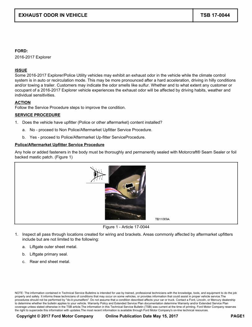
d. Rear end underbody sheet metal/body plugs. (Figure 2)
Figure 2 - Article 17-0044
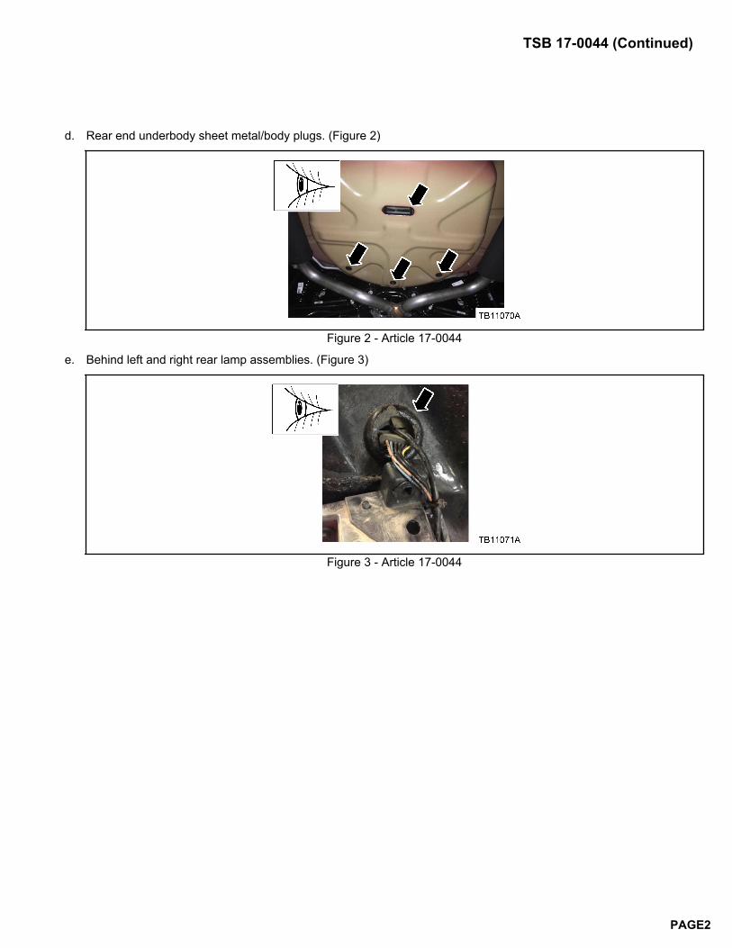
e. Behind left and right rear lamp assemblies. (Figure 3)
Figure 3 - Article 17-0044
TSB 17-0044 (Continued)
PAGE2
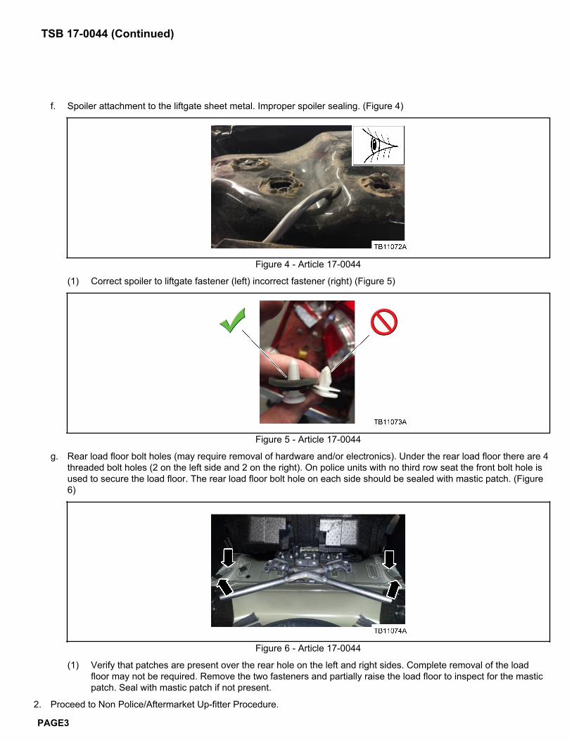
f. Spoiler attachment to the liftgate sheet metal. Improper spoiler sealing. (Figure 4)
Figure 4 - Article 17-0044
(1) Correct spoiler to liftgate fastener (left) incorrect fastener (right) (Figure 5)
Figure 5 - Article 17-0044
g. Rear load floor bolt holes (may require removal of hardware and/or electronics). Under the rear load floor there are 4threaded bolt holes (2 on the left side and 2 on the right). On police units with no third row seat the front bolt hole isused to secure the load floor. The rear load floor bolt hole on each side should be sealed with mastic patch. (Figure6)
Figure 6 - Article 17-0044
(1) Verify that patches are present over the rear hole on the left and right sides. Complete removal of the loadfloor may not be required. Remove the two fasteners and partially raise the load floor to inspect for the masticpatch. Seal with mastic patch if not present.
2. Proceed to Non Police/Aftermarket Up-fitter Procedure.
TSB 17-0044 (Continued)
PAGE3
Non Police/Aftermarket Up-fitter Service Procedure
The Non Police/Aftermarket Up-fitter Service Procedure consists of 2 separate repair routines. Most vehicles will not requirethe second procedure.
Non Police/Aftermarket Up-fitter Service Procedure 2 does not apply to vehicles equipped with the 3.7L Twin independent-variable camshaft timing (Ti-VCT), 2.3L gasoline turbocharged direct injection (GTDI) or 3.5L GTDI engines.
The body sealing steps in this procedure are critical elements in helping to manage subjective odor concerns.
1. Is the customer returning with the exhaust odor complaint after Non Police/Aftermarket Up-fitter Procedure 1 wascompleted?
a. No - proceed to Non Police/Aftermarket Up-fitter Procedure 1.
b. Yes - is the vehicle equipped with the 3.5L Ti-VCT engine?
(1) Yes - proceed to Non Police/Aftermarket Up-fitter Procedure 2.
(2) No - the procedure does not apply. Continue with normal diagnostics.
Non Police/Aftermarket Upfitter Service Procedure 1
1. Reprogram the heating ventilation air conditioning (HVAC) module to the latest calibration using IDS release 105.01 orhigher. Make sure you are connected to the internet when entering module programming to obtain the latest updates.Calibration files may also be obtained at www.motorcraftservice.com.
a. When reprogramming the HVAC, IDS will have additional questions which will require a yes response to reprogramthe module.
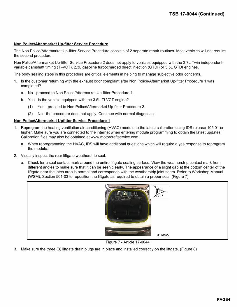
2. Visually inspect the rear liftgate weatherstrip seal.
a. Check for a seal contact mark around the entire liftgate sealing surface. View the weatherstrip contact mark fromdifferent angles to make sure that it can be seen clearly. The appearance of a slight gap at the bottom center of theliftgate near the latch area is normal and corresponds with the weatherstrip joint seam. Refer to Workshop Manual(WSM), Section 501-03 to reposition the liftgate as required to obtain a proper seal. (Figure 7)
Figure 7 - Article 17-0044
3. Make sure the three (3) liftgate drain plugs are in place and installed correctly on the liftgate. (Figure 8)
TSB 17-0044 (Continued)
PAGE4
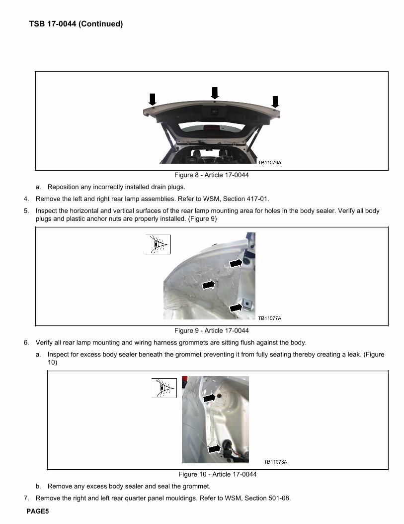
Figure 8 - Article 17-0044
a. Reposition any incorrectly installed drain plugs.
4. Remove the left and right rear lamp assemblies. Refer to WSM, Section 417-01.
5. Inspect the horizontal and vertical surfaces of the rear lamp mounting area for holes in the body sealer. Verify all bodyplugs and plastic anchor nuts are properly installed. (Figure 9)
Figure 9 - Article 17-0044
6. Verify all rear lamp mounting and wiring harness grommets are sitting flush against the body.
a. Inspect for excess body sealer beneath the grommet preventing it from fully seating thereby creating a leak. (Figure10)
Figure 10 - Article 17-0044
b. Remove any excess body sealer and seal the grommet.
7. Remove the right and left rear quarter panel mouldings. Refer to WSM, Section 501-08.
TSB 17-0044 (Continued)
PAGE5
8. Remove the right and left rear quarter panel splash shields. Refer to WSM, Section 501-08.
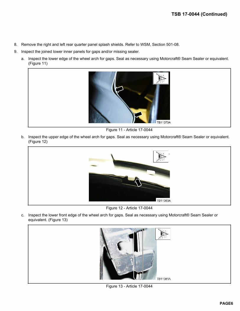
9. Inspect the joined lower inner panels for gaps and/or missing sealer.
a. Inspect the lower edge of the wheel arch for gaps. Seal as necessary using Motorcraft® Seam Sealer or equivalent.(Figure 11)
Figure 11 - Article 17-0044
b. Inspect the upper edge of the wheel arch for gaps. Seal as necessary using Motorcraft® Seam Sealer or equivalent.(Figure 12)
Figure 12 - Article 17-0044
c. Inspect the lower front edge of the wheel arch for gaps. Seal as necessary using Motorcraft® Seam Sealer orequivalent. (Figure 13)
Figure 13 - Article 17-0044
TSB 17-0044 (Continued)
PAGE6
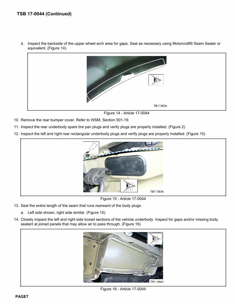
d. Inspect the backside of the upper wheel arch area for gaps. Seal as necessary using Motorcraft® Seam Sealer orequivalent. (Figure 14)
Figure 14 - Article 17-0044
10. Remove the rear bumper cover. Refer to WSM, Section 501-19.
11. Inspect the rear underbody spare tire pan plugs and verify plugs are properly installed. (Figure 2)
12. Inspect the left and right rear rectangular underbody plugs and verify plugs are properly installed. (Figure 15)
Figure 15 - Article 17-0044
13. Seal the entire length of the seam that runs rearward of the body plugs.
a. Left side shown, right side similar. (Figure 15)
14. Closely inspect the left and right side boxed sections of the vehicle underbody. Inspect for gaps and/or missing bodysealant at joined panels that may allow air to pass through. (Figure 16)
Figure 16 - Article 17-0044
TSB 17-0044 (Continued)
PAGE7
a. If any gaps or missing body sealant are found, seal with Motorcraft® Seam Sealer or equivalent.
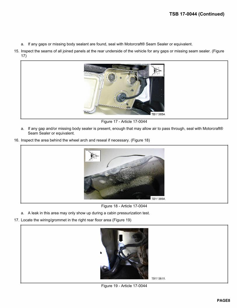
15. Inspect the seams of all joined panels at the rear underside of the vehicle for any gaps or missing seam sealer. (Figure17)
Figure 17 - Article 17-0044
a. If any gap and/or missing body sealer is present, enough that may allow air to pass through, seal with Motorcraft®Seam Sealer or equivalent.
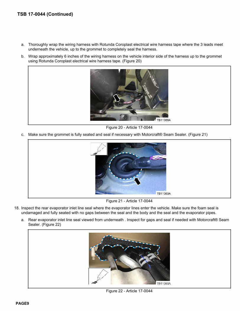
16. Inspect the area behind the wheel arch and reseal if necessary. (Figure 18)
Figure 18 - Article 17-0044
a. A leak in this area may only show up during a cabin pressurization test.
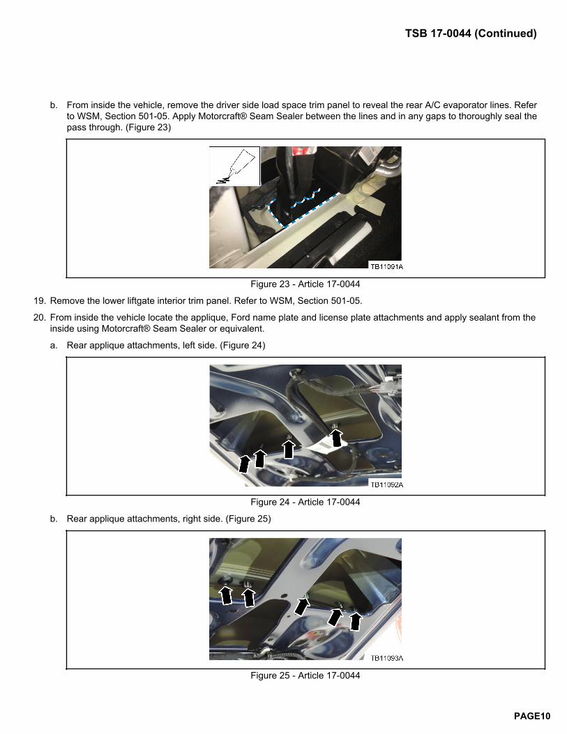
17. Locate the wiring/grommet in the right rear floor area (Figure 19)
Figure 19 - Article 17-0044
TSB 17-0044 (Continued)
PAGE8
a. Thoroughly wrap the wiring harness with Rotunda Coroplast electrical wire harness tape where the 3 leads meetunderneath the vehicle, up to the grommet to completely seal the harness.
b. Wrap approximately 6 inches of the wiring harness on the vehicle interior side of the harness up to the grommetusing Rotunda Coroplast electrical wire harness tape. (Figure 20)
Figure 20 - Article 17-0044
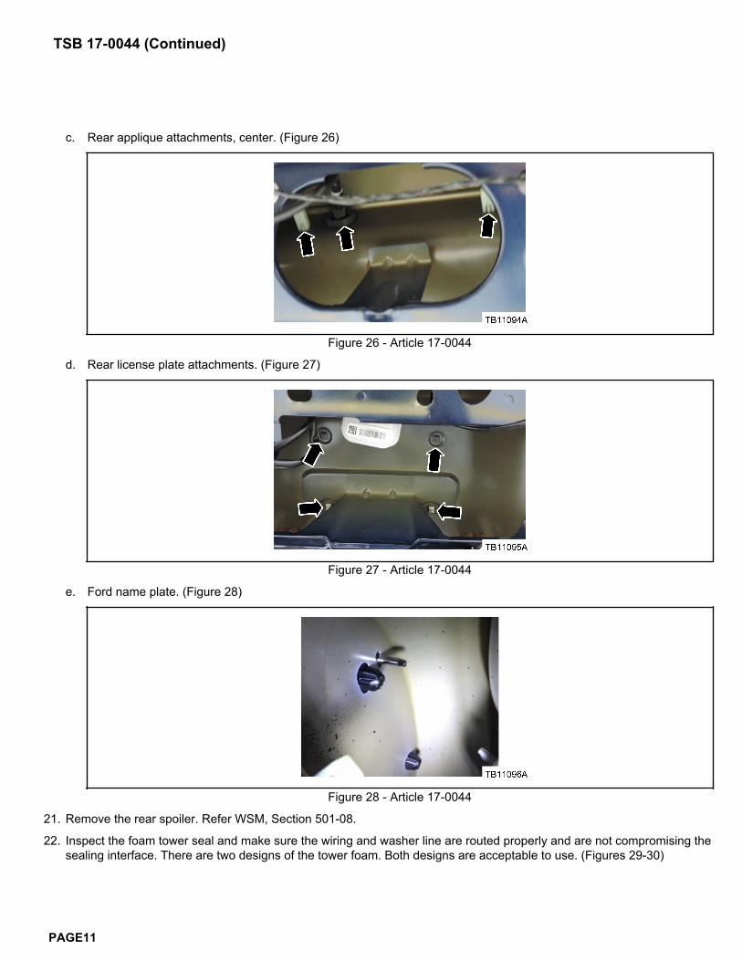
c. Make sure the grommet is fully seated and seal if necessary with Motorcraft® Seam Sealer. (Figure 21)
Figure 21 - Article 17-0044
18. Inspect the rear evaporator inlet line seal where the evaporator lines enter the vehicle. Make sure the foam seal isundamaged and fully seated with no gaps between the seal and the body and the seal and the evaporator pipes.
a. Rear evaporator inlet line seal viewed from underneath . Inspect for gaps and seal if needed with Motorcraft® SeamSealer. (Figure 22)
Figure 22 - Article 17-0044
TSB 17-0044 (Continued)
PAGE9
b. From inside the vehicle, remove the driver side load space trim panel to reveal the rear A/C evaporator lines. Referto WSM, Section 501-05. Apply Motorcraft® Seam Sealer between the lines and in any gaps to thoroughly seal thepass through. (Figure 23)
Figure 23 - Article 17-0044
19. Remove the lower liftgate interior trim panel. Refer to WSM, Section 501-05.
20. From inside the vehicle locate the applique, Ford name plate and license plate attachments and apply sealant from theinside using Motorcraft® Seam Sealer or equivalent.
a. Rear applique attachments, left side. (Figure 24)
Figure 24 - Article 17-0044
b. Rear applique attachments, right side. (Figure 25)
Figure 25 - Article 17-0044
TSB 17-0044 (Continued)
PAGE10
c. Rear applique attachments, center. (Figure 26)
Figure 26 - Article 17-0044
d. Rear license plate attachments. (Figure 27)
Figure 27 - Article 17-0044
e. Ford name plate. (Figure 28)
Figure 28 - Article 17-0044
21. Remove the rear spoiler. Refer WSM, Section 501-08.
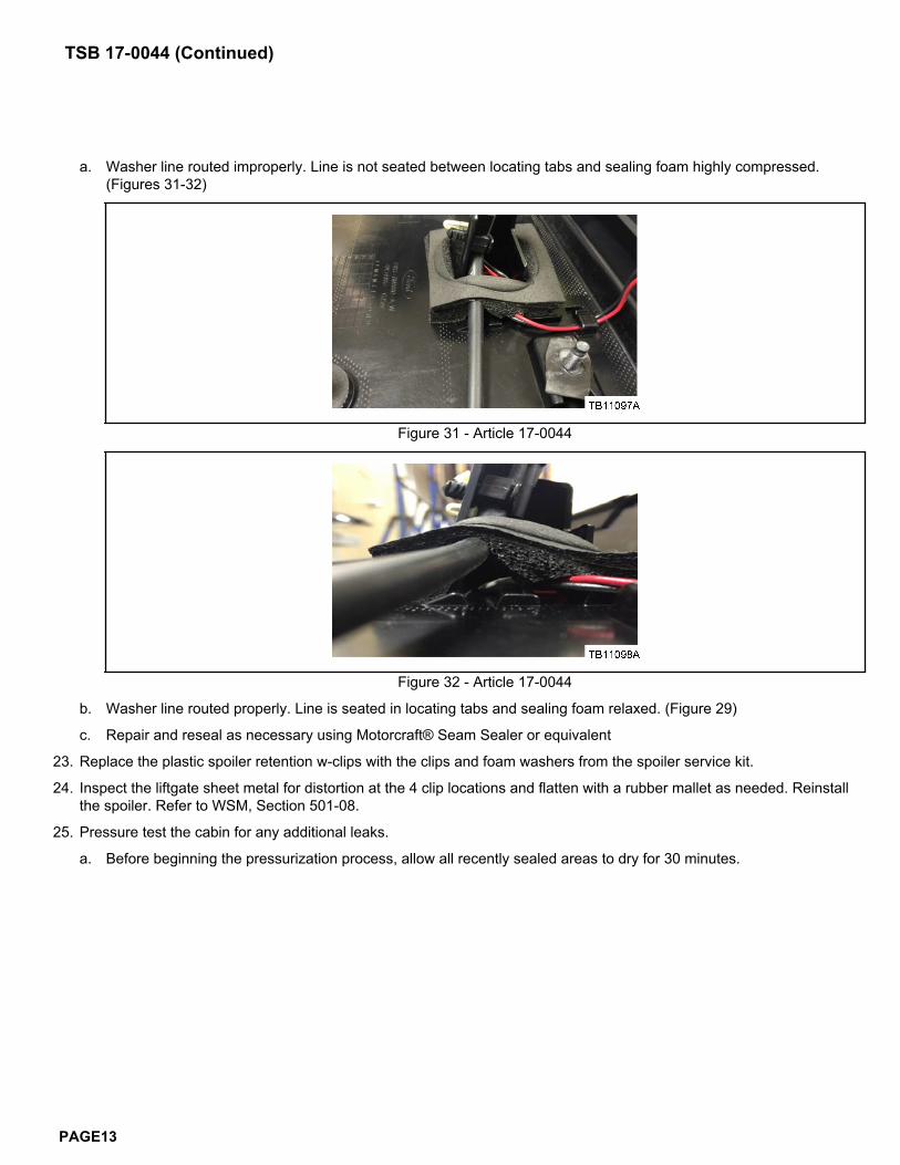
22. Inspect the foam tower seal and make sure the wiring and washer line are routed properly and are not compromising thesealing interface. There are two designs of the tower foam. Both designs are acceptable to use. (Figures 29-30)
TSB 17-0044 (Continued)
PAGE11
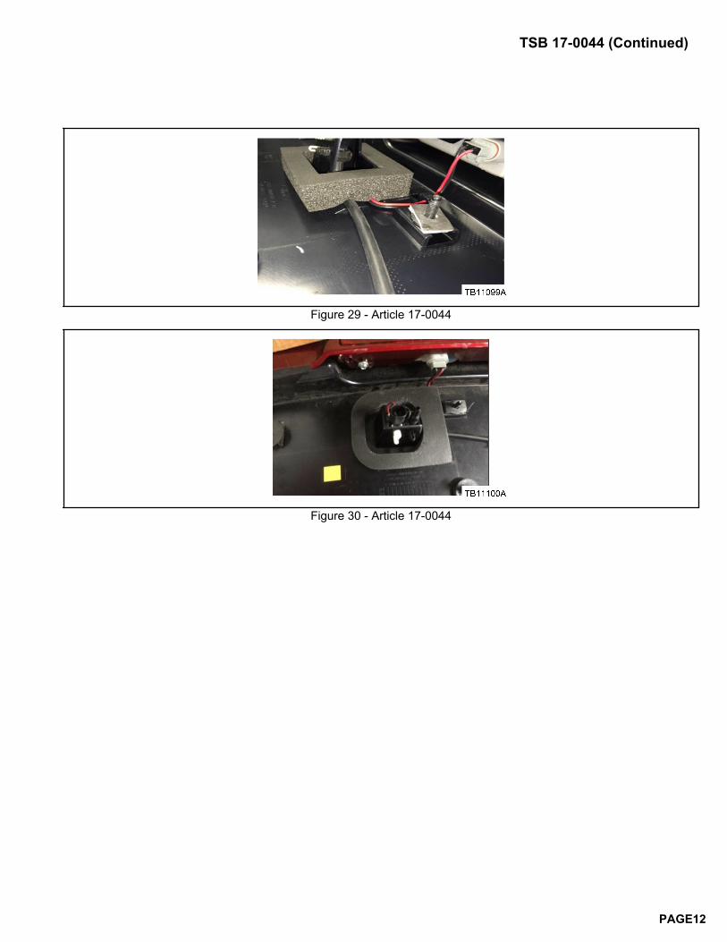
Figure 29 - Article 17-0044
Figure 30 - Article 17-0044
TSB 17-0044 (Continued)
PAGE12
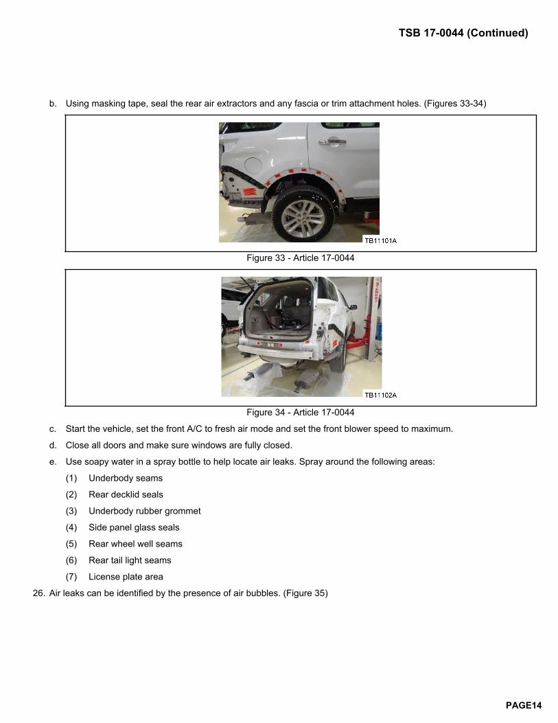
a. Washer line routed improperly. Line is not seated between locating tabs and sealing foam highly compressed.(Figures 31-32)
Figure 31 - Article 17-0044
Figure 32 - Article 17-0044
b. Washer line routed properly. Line is seated in locating tabs and sealing foam relaxed. (Figure 29)
c. Repair and reseal as necessary using Motorcraft® Seam Sealer or equivalent
23. Replace the plastic spoiler retention w-clips with the clips and foam washers from the spoiler service kit.
24. Inspect the liftgate sheet metal for distortion at the 4 clip locations and flatten with a rubber mallet as needed. Reinstallthe spoiler. Refer to WSM, Section 501-08.
25. Pressure test the cabin for any additional leaks.
a. Before beginning the pressurization process, allow all recently sealed areas to dry for 30 minutes.
TSB 17-0044 (Continued)
PAGE13
b. Using masking tape, seal the rear air extractors and any fascia or trim attachment holes. (Figures 33-34)
Figure 33 - Article 17-0044
Figure 34 - Article 17-0044
c. Start the vehicle, set the front A/C to fresh air mode and set the front blower speed to maximum.
d. Close all doors and make sure windows are fully closed.
e. Use soapy water in a spray bottle to help locate air leaks. Spray around the following areas:
(1) Underbody seams
(2) Rear decklid seals
(3) Underbody rubber grommet
(4) Side panel glass seals
(5) Rear wheel well seams
(6) Rear tail light seams
(7) License plate area
26. Air leaks can be identified by the presence of air bubbles. (Figure 35)
TSB 17-0044 (Continued)
PAGE14
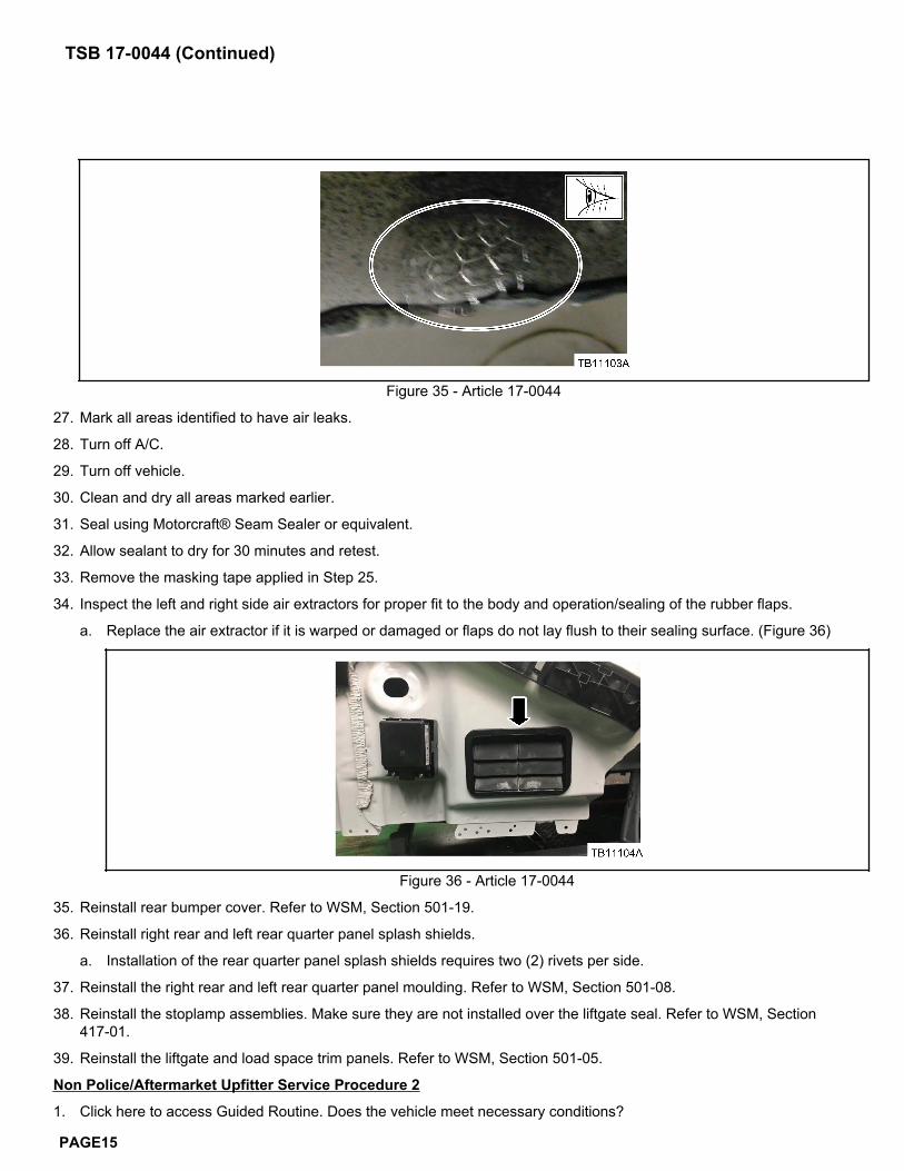
Figure 35 - Article 17-0044
27. Mark all areas identified to have air leaks.
28. Turn off A/C.
29. Turn off vehicle.
30. Clean and dry all areas marked earlier.
31. Seal using Motorcraft® Seam Sealer or equivalent.
32. Allow sealant to dry for 30 minutes and retest.
33. Remove the masking tape applied in Step 25.
34. Inspect the left and right side air extractors for proper fit to the body and operation/sealing of the rubber flaps.
a. Replace the air extractor if it is warped or damaged or flaps do not lay flush to their sealing surface. (Figure 36)
Figure 36 - Article 17-0044
35. Reinstall rear bumper cover. Refer to WSM, Section 501-19.
36. Reinstall right rear and left rear quarter panel splash shields.
a. Installation of the rear quarter panel splash shields requires two (2) rivets per side.
37. Reinstall the right rear and left rear quarter panel moulding. Refer to WSM, Section 501-08.
38. Reinstall the stoplamp assemblies. Make sure they are not installed over the liftgate seal. Refer to WSM, Section417-01.
39. Reinstall the liftgate and load space trim panels. Refer to WSM, Section 501-05.
Non Police/Aftermarket Upfitter Service Procedure 2
1. Click here to access Guided Routine. Does the vehicle meet necessary conditions?
TSB 17-0044 (Continued)
PAGE15
a. Yes - proceed to Step 2.
b. No - return the vehicle to the customer. No additional repairs are available.
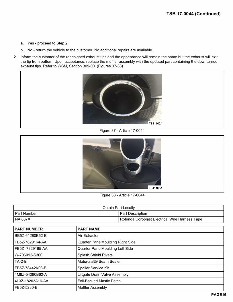
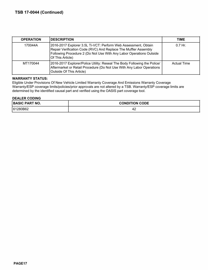
2. Inform the customer of the redesigned exhaust tips and the appearance will remain the same but the exhaust will exitthe tip from bottom. Upon acceptance, replace the muffler assembly with the updated part containing the downturnedexhaust tips. Refer to WSM, Section 309-00. (Figures 37-38)
Figure 37 - Article 17-0044
Figure 38 - Article 17-0044
Obtain Part LocallyPart Number Part DescriptionNAI837X Rotunda Coroplast Electrical Wire Harness Tape
PART NUMBER PART NAMEBB5Z-61280B62-B Air ExtractorFB5Z-7829164-AA Quarter PanelMoulding Right SideFB5Z- 7829165-AA Quarter PanelMoulding Left SideW-706092-S300 Splash Shield RivetsTA-2-B Motorcraft® Seam SealerFB5Z-78442K03-B Spoiler Service Kit4M8Z-54280B62-A Liftgate Drain Valve Assembly4L3Z-18203A16-AA Foil-Backed Mastic PatchFB5Z-5230-B Muffler Assembly
TSB 17-0044 (Continued)
PAGE16
OPERATION DESCRIPTION TIME170044A 2016-2017 Explorer 3.5L Ti-VCT: Perform Web Assessment, Obtain
Repair Verification Code (RVC) And Replace The Muffler AssemblyFollowing Procedure 2 (Do Not Use With Any Labor Operations OutsideOf This Article)
0.7 Hr.
MT170044 2016-2017 Explorer/Police Utility: Reseal The Body Following the Police/Aftermarket or Retail Procedure (Do Not Use With Any Labor OperationsOutside Of This Article)
Actual Time
WARRANTY STATUS:Eligible Under Provisions Of New Vehicle Limited Warranty Coverage And Emissions Warranty CoverageWarranty/ESP coverage limits/policies/prior approvals are not altered by a TSB. Warranty/ESP coverage limits aredetermined by the identified causal part and verified using the OASIS part coverage tool.
DEALER CODINGBASIC PART NO. CONDITION CODE61280B62 42
TSB 17-0044 (Continued)
PAGE17