EXFO-OLTS vs OTDR - VIRZ Expertennetzwerk · OTDR settings (pulse, range, averaging duration) are...
47
1 © 2016 EXFO Inc. All rights reserved. OLTS vs OTDR Christian Till, Application Engineer 2016/12/09 Tier-2 Expert; How far from Tier-1?
Transcript of EXFO-OLTS vs OTDR - VIRZ Expertennetzwerk · OTDR settings (pulse, range, averaging duration) are...

1© 2016 EXFO Inc. All rights reserved.
OLTS vs OTDR
Christian Till, Application Engineer
2016/12/09
Tier-2 Expert; How far from Tier-1?

2© 2016 EXFO Inc. All rights reserved.
›Bandwidth grows like crazy… Global DC traffic 5ZB now, 10.4ZB 2019
›Hyperscale are going 100% SMF… planning 200-400G intra-DC!
›MMF OM5 standard has been adopted… SWDM4 transceivers rise
›10 GbE (SFP) is OK at top-of-the rack switch, 40G/100G+ Leaf-Spine
›2016: Year of 25 GbE (SFP) and 4x25G lane, 100G Serial duplex OR Parralel
›Mobile & Telco operators re-architecture their CO in Data Center (CORD)
›Existing infrastructure (LC/UPC patch panels) are more sensitive to back reflection…
›What is the value of testing?
Why this industry is exciting!

3© 2016 EXFO Inc. All rights reserved.
Standard Testing Requirements
Tier-1Certification Tests
Tier-2Extended Tests & Troubleshooting
Normative Measurements
� Polarity (VFL)
� Insertion Loss (IL)� Length
Informative Measurements
� Polarity (VFL)
� Insertion Loss� Length� Connector and Splice
Loss� Connector Reflectance
Recommended Method
� LS/PM
� OLTS/Certifier
Recommended Method
� OTDR/iOLM

4© 2016 EXFO Inc. All rights reserved.
IEEE Standards (published or under development)
IEEE 802.3bs ���� 200/400G Fiber
� Includes MMF & SMF options
� SMF� Duplex Series up to
500m/2Km/10Km
� MMF � Parallel 16x25G.
Source: Commscope
5© 2016 EXFO Inc. All rights reserved.
What fiber & connector types to choose?
Serial Duplex – LC connectors Parralel Optics - Multi-Fiber MPO/MTP
� Ceramic ferrule (zirconia)
� One fiber per connector
� Typically used in duplex (transmit & receive)
� Common types include LC
� Polymer ferrule
� Multiple fibers in linear array (8, 12, 24)
� High-density connectivity in single connector.
� Common type is MPO or MTP®
MMF (OM4, OM5) UPC versus SMF (OS1) / APC or UPC

6© 2016 EXFO Inc. All rights reserved.
Construction (Tier-1 test)
Only OLTS (or LSPM) defined for Tier 1 testing

7© 2016 EXFO Inc. All rights reserved.
Troubleshooting (Tier-2 test)
Copper (CAT)
Fiber
FIPFIP
FIP FIP
FIP
FIP
Mapping faults along the fiber requires the use of an iOLM-OTDR
iOLM
Receive fiber
Serial – DuplexTransceiversSMF or MMF
Launch fiber
Leaf
Spine
iOLM-OTDR is the only
tool for:
• Detect Macrobends
• Measure and
validate proper
return loss of
connectors
• Detect excessive
connector loss due
to contamination,
damage
• Identify the position
of a fiber fault or
issue
MTP/MPO trunks

8© 2016 EXFO Inc. All rights reserved.
Move Add & Change (MAC) Transceivers
Leaf
Spine
Copper (CAT)
Fiber
FIPFIP
FIP FIP
FIP
FIP
Serial – DuplexTransceiversSMF or MMF
OLTS
OLTS
OLTS and Fiber Inspection probe, because it’s faster (3 sec.)!
1- Validate channel is
Pass with OLTS
2- Clean & inspect
connectors
3- Connect new
transceivers/ link
4- Validate the link
works properly
5- If not proper,
transceiver is likely to
be the issue.
MTP/MPO trunks

9© 2016 EXFO Inc. All rights reserved.
Can OTDR provides total fiber link attenuation/loss measurement as
accurately as OLTS provides, “in the field”?
1. Slight variations of fiber geometry along the fiber under test induce some errors
in the OTDR measurement when tested from a single direction.
2. When testing link attenuation, the local errors due to fiber geometry mismatch
are not cumulative. The link attenuation error only depends on launch vs
receive fiber geometry.
3. Averaging measurements performed from both ends remove these errors
(bidirectional averaging).
OTDR for Tier-1 testing..?

10© 2016 EXFO Inc. All rights reserved.
Why Encircled Flux (EF) is Important
OFL/Mandrel Wrap per TIA-426-14-A,
Encircled Flux (EFL) TIA-426-14-B, Annex A
Source: Belden (2011)
Optical loss testing in the field, not as simple as it seems
VCSELLED
Ideal/ EF
conditioned

11© 2016 EXFO Inc. All rights reserved.
Uncertainty contributor Source of errors Value Comment
Light source instability Test Equipment +/- 0.05 dB Typical instability of a light source as
per IEC 61282-14
Light source wavelength Test Equipment/
FUT (spectral
dependency)
Spectral loss dependence
for 300 m at 850 nm +/- 30
nm
Light source wavelength tolerance
specified as per ISO/IEC-14763-3
(2016)
MMF Launch condition Test Equipment +/- 10% x 1.6 dB (850 nm) For Encircled Flux compliant source
Mating reproducibility FUT +/- 0.1 dB As per IEC 61282-14
Reference connector
repeatability
FUT +/- 0.05 dB As per IEC 61282-14
LSPM: Main uncertainty contributors
MMF loss measurement using a 1-cord reference, at 850 nm for a link of 300 m, with a total loss of 1.6 dB
+/- 0.27 dB (850 nm) total uncertainty ref. IEC TR 61282-14 (2016)
(considers statistical addition of all contributors, weight dependent)

12© 2016 EXFO Inc. All rights reserved.
›OLTS measurement has been made in duplex (1-cord reference)
›Typical FUT:
MMF: OLTS reference set-up
EF compliant EF compliantREF-Grade (3m) REF-Grade (3m)

13© 2016 EXFO Inc. All rights reserved.
MMF: OLTS attenuation (850 nm)
+/- 0.27 dB
Uncertainty of light-source / power meter
measurement on a MMF link as per
IEC TR 61282-14 (2016)
Reproductibility of the OLTS measurement is consistent with the expected measurement
uncertainty (using three different OLTS).
Test conditions:
3OLTS, TJ-REF
Jumpers

14© 2016 EXFO Inc. All rights reserved.
Uncertainty
contributor
Comment
Launch and receive
test cord fiber
geometry
Fiber geometry (mainly the core size and the numerical aperture of the fiber) influence the amount of
backscatter signal that a fiber generates (source uncertainty in the measurement of individual connectors and
splices loss with an OTDR).
The uncertainty contribution due to fiber geometry mismatch is +/- 0.19 dB for SMF assuming a (fairly typical)
fiber core specification of 9.2 +/- 0.4 mm. Performing bidirectional OTDR measurement will remove this error.
Loss spectral
dependency of fiber
The fact that the LS and the iOLM can have slightly different nominal wavelengths will cause some deviation in
the measurements due to the spectral attenuation characteristics of the fiber (in general, connectors and splices
losses have low dependencies on nominal wavelength, but not the fiber)
OTDR trace noise OTDR is dependent on the right adjustment of OTDR test parameters (pulse length, distance range and
averaging time).
Trace recovery When a strong reflectance occurs close to the end of the link under test, it may cause some error on the
measurement of the backscatter level on the receive test cord
Proper measurement
of link loss
Minimum receive test cord length depends on worse case reflectance that is expected.
Trace analysis/event
detection robustness
In general, OTDR performances are highly dependent on the quality of the “raw” OTDR trace (clean trace, no
distortion or artefacts) as well as the robustness of the algorithms performing trace analysis (event detection
and characterization).
OTDR - Main uncertainty contributors
15© 2016 EXFO Inc. All rights reserved.
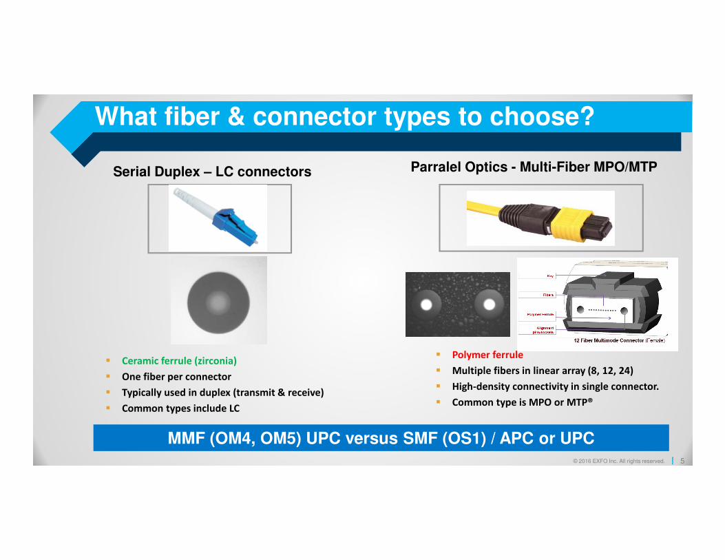
iOLM IL measurement
- In the iOLM application, specify the Launch and Receive lengths
- Launch an iOLM acquisition and read the span loss.
DUT iOLM
SPSB-EF SPSB-100m
PM
MMF: iOLM reference set-up

16© 2016 EXFO Inc. All rights reserved.
Consistent results
over multiple instruments.
Test conditions:
3OTDRs, Launch & Receive fibers
Reproductibility of the iOLM measurement exhibits very good consistency (using
three different iOLM) .
MMF: iOLM attenuation (850 nm)
EXFO is willing to share its procedure for
comparison.

17© 2016 EXFO Inc. All rights reserved.
MMF: OLTS vs iOLM attenuation (850 nm)
iOLM measures slightly lower
attenuation than OLTS
(average bias -0.25 dB)
Test conditions:
3OTDRs, Launch &
Receive fibers
OLTS, TJ-REF Jumpers
This bias is explained by the fundamental mechanism of backscattering which produces a
slightly underfilled equivalent measurement (even if the iOLM is conditioned for EF).

18© 2016 EXFO Inc. All rights reserved.
SMF: iOLM reference set-up (1310/ 1550 nm)
A reference measurement is required to validate accuracy of OTDR method. The reference is done using Light
Source (LS) and Power Meter (PM). The best possible conditions are set for the reference:
LS is using OTDR source in CW mode to ensure same wavelength as OTDR measurement
A Polarization scrambler is used to reduce PDL effects
A high-linearity, cooled detector, Laboratory PM is used
Ambient temperature is 23 C +/- 1C
Long warm-up are allowed (>30 minutes) before measurements
This setup can provide an attenuation reference with 0.01 dB uncertainty.
OTDR settings (pulse, range, averaging duration) are appropriate to ensure a low-noise measurement.
Launch and receive cords are of sufficient lengths.
Polarization Scrambler
Launch Fiber
Power Meter
OTDR1310/1550
1625
Polarization Scrambler
Launch Fiber
FUTReceive
FiberPower Meter
OTDR1310/1550
1625
P1
P2
AttenuationREF = P1-P2
Presented at TR-42.11 meeting, Philadelphia 2016.10.08

19© 2016 EXFO Inc. All rights reserved.
SMF: Single Direction OTDR Measurement
Launch & receive from same fiber type & manufacturer (to reduce uncertainty due to MFD mismatch)
+/- 0.15 dB
Test
conditions:
5OTDRs
Launch fibers
Receive fibers

20© 2016 EXFO Inc. All rights reserved.
SMF: Bi-directional OTDR Measurement
Bi-directional OTDR measurement: cancel out Backscatter characteristics between launch & receive fibers
+/- 0.1 dB
Test
conditions:
5OTDRs
Launch fibers
Receive fibers

21© 2016 EXFO Inc. All rights reserved.
� For SMF, only launch & tail cords backscatter characteristics are important for link attenuation.
� When launch & tail cords have the same backscatter characteristics, there is no error introduced in the link attenuation.
� For MMF, there is a slight bias between OTDR and LSPM due to the nature of the backscattering process.
� OTDR can provide extremely accurate fiber link attenuation measurements for SMF and fairly accurate for MMF.
� OTDR should be considered as a valid tool/method for Tier 1 characterization of SMF.
� For characterization of MMF, improvements are on the way.
Conclusions

22© 2016 EXFO Inc. All rights reserved. 22© 2016 EXFO Inc. All rights reserved.

23© 2016 EXFO Inc. All rights reserved.
Reflectance issues at the patch panel?
Source: EXFO Application Note 327 – Touching on Failure: Sources of Singlemode Fiber Issues in the Data Center, December 2016
10-12 dB average change (clean vs. oil)
Strict correlation (clean vs. oil)0.70.70.70.7
0.60.60.60.6
0.50.50.50.5
0.40.40.40.4
0.30.30.30.3
0.20.20.20.2
0.10.10.10.1
0000
70707070
60606060
50505050
40404040
30303030
20202020
10101010
0000
Thresholds (customers):
Standards (TIA-568.3-D (2016, b.3), IEC-11801 (2010): SMF 35dB, MMF 20dB
Direct modulation (CWDM4, PSM4, PAM4): -40 to -45dB CRC issues
Coherent-based: -30dB = EDFA APR mode issue
Finger oil

24© 2016 EXFO Inc. All rights reserved.
MTP/MPO based links (Tier-1 & Tier-2)
Pre-installation quality test
Migration to 100G/ 200G/ 400G
1 2 3
Parallel optics

25© 2016 EXFO Inc. All rights reserved.
Server to server communication inside a DC
26© 2016 EXFO Inc. All rights reserved.
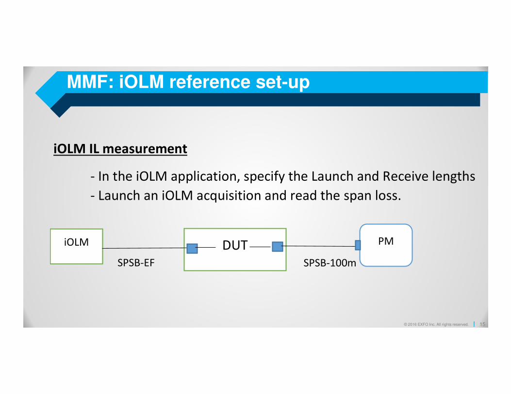
Leaf – Spine topology: Redundant, scalable
• Efficient use of most
affordable components,
QSFP28, switches
• Each servers in the data
center is linked with all the
other servers with the
same number of hops.
• Can be configured in Layer
2 (switched) or Layer 3
(routed)

27© 2016 EXFO Inc. All rights reserved.
OM5 MMF Considerations (SWDM4)
Source: Commscope
Test parameter Test vendor advices
Attenuation Testing 850 nm worst case appears the best practice850 nm presents higher attenuation than 950 or 1300 nm
ORL / Reflectance VCSEL is more sensitive to ORL than LEDORL is wavelength independent, not light source independent
Dispersion (Chromatic and Modal)
Expect the smallest differential mode delay (DMD) specs possible for WBMMFUnless stated otherwise by the fiber manufacturer, CD (chromatic) and modal dispersion shall be considered OK by design
Source: EXFO

28© 2016 EXFO Inc. All rights reserved. 28© 2016 EXFO Inc. All rights reserved.
What are the main contributors of uncertainty?
Light Source / Power Meter (OLTS) OTDR
� Light Source (LS) instability (warming time)
� LS wavelength drift after referencing
� Reference test jumpers conditions
� Multimode reference test jumpers launch condition
� Mating reproducibility
� Reference connector repeatability
� LSPM vs OLTS (coupler PDL)
� Ideal LSPM vs OTDR (same for SM, slight difference for MM)
� OTDR loss linearity (vs loss uncertainty)
� Launch vs receive fiber geometry (different backscattering ratio)
� Noise on trace (vs pulse, vs averaging time)
� Trace recovery (vs reflectance, vs length of receive fiber)
� Echos
� Trace analysis/ event detection robustness
1- Equipment variation (repeatability)
2- Product variation (FUT variation)
Respect calibration period and change
your test jumpers…

29© 2016 EXFO Inc. All rights reserved.
UNCERTAINTY SPECIFICATIONS
• Specifications of FTB-730-iOLM testing of short span links (3m<Link<500m)
• Results valid at Results valid at 1310 and 1550 nm at 23±3°C
• Launch/ Receive (matched): 150m (for FUT <5 dB IL) or 500m (for FUT <12 dB IL)
• Reflectance specifications valid for L ≥15 m
OTDR - iOLMSpecification (dB)
Typical Notes
Link IL uncertainty 0.1 Link loss for 3m<L<500m or <12 dB.
Single connector IL uncertainty 0.1 15m≤ L <500m
Reflectance uncertainty 0.75 From -45 to -65 dB
Short link ORL uncertainty 1For L<15 m. Includes two connectors and fibre loss
uncertainties. Events may be merged.
• USING SUITABLE REFERENCE CABLES
Source & Power meter - OLTSSpecification (dB)
Typical Notes
Link IL uncertainty 0.1 (0.2) PM/LS: Loss <46 dB (OLTS: Loss <55 dB)
Single connector IL uncertainty N/AReflectance uncertainty N/A
Short link ORL uncertainty 0.5 (1) PM/LS: mandrel method (OLTS: Up to 55 dB ORL for APC)

30© 2016 EXFO Inc. All rights reserved. 30© 2016 EXFO Inc. All rights reserved.
Why Encircled Flux method is so important?
LED
VCSEL
IDEAL (EF)
EF ready, no external mode conditioner required
EF ready, external mode conditioner required
10G+ fiber-optic testing, requires EF metric,
launching condition to satisfy the required
REPEATABILITY, REPRODUCIBILITY and OPTIMAL
UNCERTAINTY

31© 2016 EXFO Inc. All rights reserved. 31© 2016 EXFO Inc. All rights reserved.
Is up to 30% uncertainty acceptable?
OFL/Mandrel Wrap per TIA-426-14-A,
Encircled Flux (EFL) TIA-426-14-B, Annex A
Source: Belden (2011)
Optical loss testing in the field, not as simple as it seems
TIA-568 C.3 : 3.5dB (OM1-OM4)
IEEE 802.3ae 10GBASE-LX4 : 2dB (OM2-OM4)
IEEE 802.3ba 40/100GBASE-SR4 : 1.5dB (OM4)

32© 2016 EXFO Inc. All rights reserved.
OLTS/ PM-LS / certification
LC-MTP⁄MTP-LC (1G/10G)TX RX
100 m OM4, 2km OS1
<3 seconds, 2 wavelengths Duplex, bi-directional, EF testingOLTS IL = 1.27 dB
TIA-568-C.3 – ISO/IEC-14763.3 = 3.5 dB
IEEE802.3.ba 40/100GBASE-SR4 (4x25) = 1.9 dB
Two evolutive tablet-inspired Platforms
Expert guidance, every step of the way
On-board multistandard Certification
Reduced cost of ownership
TX RX
MAX-940-QUAD

33© 2016 EXFO Inc. All rights reserved. 33© 2016 EXFO Inc. All rights reserved.
Is MMF dead? I think not: WBMMF (SWDM4)
Wideband Multimode Fiber (WBMMF)
Source: Commscope
2 fibers / 850 nm
880 nm910 nm940 nm
Test parameter Test vendor advices
Attenuation Testing 850 nm worst case appears the best practice850 nm presents higher attenuation than 950 or 1300 nm
ORL / Reflectance VCSEL is more sensitive to ORL than LEDORL is wavelength independent, not light source independent
Dispersion (Chromatic and Modal)
Expect the smallest differential mode delay (DMD) specs possible for WBMMFUnless stated otherwise by the fiber manufacturer, CD (chromatic) and modal dispersion shall be considered OK by design
Chromatic Dispersion
Modal Dispersion
Pulse spreading
Source: EXFO

34© 2016 EXFO Inc. All rights reserved. 34© 2016 EXFO Inc. All rights reserved.
Questions, checklist & test objectives
# Checklist Prerequisite Note
Important: Test instruments calibration
and reference test jumpers
Change test jumpers each 200-300 connections or
if they are scratched.
Measurement uncertainty depends on these
factors.
Input: Multimode or Singlemode fiber Keep in mind the 150 m reach limitation for MMF
(OM4/WBMMF).
Tighter budget for 40G & 100G over OM4
MMF / WBMMF, SMF more $
Input: What volume or counts of fiber
to test
What is the test task: fiber certification,
troubleshooting, warranty registration
Set your objectives carefully.
Decision: Test tools, testing time &
test procedures
OLTS helps screen suspect links (ORL)
OTDR maps fault and connectors RL
Test instruments alone do not solve
everything!
1 Contaminants on the connector
endfaces
Clean & inspect, first time right. Ultimate baseline for an effective and
efficient optical testing!
2 Mastering test repeatability,
uncertainty
Multimode fiber, Encircled Flux compliant
equipment & procedure.
Respect calibration and test jumpers quality!
3 Test data valorization Documentation system and processes Best practices to speed up future trouble
shooting.
4 Managing 10G to 100G+ migration:
connectors’ RL impact
RL can kill a network at 25 Gbps line rate… 25/50 Gbps more demanding than
10 Gbps…

35© 2016 EXFO Inc. All rights reserved. 35© 2016 EXFO Inc. All rights reserved.
OLTS vs iOLM-OTDR / RL, BR, ORL… Tier-1 & 2
Return loss (RL) is the loss of power in the signal returned/reflected by a discontinuity in a transmission line or optical fiber. This
discontinuity can be a mismatch with the terminating load or with a device inserted in the line (also called Reflectance or back
reflection ).
Optical Return Loss (ORL) is a measure taken from one end of the total energy reflected back to the source by all the interfaces
due to a variation of the index of refraction (IOR), breaks, voids, backscatter, etc., created inside a component or along a link.
LC LC
iOLM
LaunchReceive
End-to-end
iOLM - OTDR
OLTS FasTest Simplex

36© 2016 EXFO Inc. All rights reserved. 36© 2016 EXFO Inc. All rights reserved.
EXAMPLE

37© 2016 EXFO Inc. All rights reserved. 37© 2016 EXFO Inc. All rights reserved.
OLTS/ ORL: screening & link certification
MAX-945iCERT-QUAD
Targeted applications
• Move, Add and Changes (MACs) of pluggables optics
• Construction, certification of total loss budget (tier-1)
MAX-945iCERT-QUAD
500 ft.
(150 m)
1- OLTS
1- OLTS2- FIP3- iOLM
1- OLTS2- iOLM

38© 2016 EXFO Inc. All rights reserved. 38© 2016 EXFO Inc. All rights reserved.
iOLM – OTDR single fiber
100G-SWDM4
MDA
IDA
DCI WDM
ToR
OTDR-iOLM positions faults,
loss, reflectance and provide
link loss and ORL.
Threshold and standard
certification-based Pass/Fail.
LC Patch panel
LC patch panel
1.5 dB / 150 m (OM4)
Standard OM3
SPSB-EF-30m
Launch
30m Receive

39© 2016 EXFO Inc. All rights reserved. 39© 2016 EXFO Inc. All rights reserved.
iOLM – OTDR software interface
OTDR-iOLM positions faults,
loss, reflectance and provide
link loss and ORL.
Threshold and standard
certification-based Pass/Fail.

40© 2016 EXFO Inc. All rights reserved. 40© 2016 EXFO Inc. All rights reserved.
Testing MPO

41© 2016 EXFO Inc. All rights reserved. 41© 2016 EXFO Inc. All rights reserved.
MTP/MPO cable configurations (polarity, types)

42© 2016 EXFO Inc. All rights reserved. 42© 2016 EXFO Inc. All rights reserved.
Adapter
MPO Unpinned (Female)
MPO Pinned (Male)
MPO Guiding holes
MPO Guiding pins

43© 2016 EXFO Inc. All rights reserved. 43© 2016 EXFO Inc. All rights reserved.
Physical ContactThe Physical Contact area is the critical
joining point in the fiber network.
If no clean physical connection, the light
path is disrupted and the connection is
compromised.
Multiple connects-disconnects can create fiber
misalignments (loose pin/ hole or memory shape related
issues)

44© 2016 EXFO Inc. All rights reserved. 44© 2016 EXFO Inc. All rights reserved.
LC serial duplex – MTP/MPO trunk
catastrophic

45© 2016 EXFO Inc. All rights reserved. 45© 2016 EXFO Inc. All rights reserved.
FIP MTP/ MPO inspection auto-center / focus
Low mag view PIP (100X):
Allows to see which fiber is being
inspected in High magnification
High mag view (400X):
Highest Magnification on the market
Auto-center + Auto Focus
FIP controls:� AutoCenter
� AutoFocus
� Capture
� Analysis
MTP12 – MTP24 (MM/SM)

46© 2016 EXFO Inc. All rights reserved. 46© 2016 EXFO Inc. All rights reserved.
10G MTP/ MPO trunk test
Step 1: Pre-installation quality test Step 2: End to end LC-LC permanent link test

47© 2016 EXFO Inc. All rights reserved.