
Executive Summary - Pennsylvania State University · 2006-10-26 · Executive Summary Greg...
37
Transcript of Executive Summary - Pennsylvania State University · 2006-10-26 · Executive Summary Greg...


Executive Summary Greg Kochalski JW Marriott, Grand Rapids, MI Structural October 27, 2006 Advisor: Boothby
Purpose: The goal of this report is to investigate alternative floor systems for the flat plate system used in the JW Marriott. Once the alternatives have been analyzed, I will determine which systems are and are not viable based on numerous economic, construction, structural, and architectural criteria. Alternative Systems: Five alternate systems were investigated as alternatives for the JW.
1. Two Way Flat Slab with Drop Panels Figure A. JW Marriott and its Flat Plate System
2. Two Way Flat Plate 3. One Way Flat Plate with
Beams* 4. Hollow Core Plank 5. Composite Steel Figure A. JW Marriott and Flat Plate system
Conclusion: The current one way flat plate system performs best to meet the vision of the architect. This includes unobstructed views from the guest rooms, greater license with interior partitions, freedom with ceiling finishes, and mechanical/electrical system routing ease. The high aspect ratio, >2, lends itself best to the system used. With a few of the alternate systems it is possible to limit interior partition width to the current10 inches. However the material and construction savings do not outweigh the uniformity of construction and architectural sacrifices. In addition the bay size and floor loads are not large enough to take full advantage of the two way systems’ benefits. The most viable alternatives are two way flat plate and composite steel, due to reduction in slab thickness and improved seismic response, respectively. Simple construction techniques and formwork drive project costs down. Smaller vertical runs increase economic gains with other building systems. Given the unique shape of the JW Marriott I believe that the existing floor system is the best choice.

Table of Contents Introduction 1 Existing Structural Description 2 Alternate Structural Systems 3
Two Way Flat Slab with Drop Panels 4 Two Way Flat Plate 5 One Way Flat Slab with Beams 6 Hollow Core Plank 7 Composite Steel 8
Comparison and Conclusion 9 Appendices 10

1
Introduction Description: The JW Marriottis a 24 story hotel currently under construction in Grand Rapids, Michigan and is being constructed under the 2003 Michigan Building Code. The 2003 MBC references the IBC 2003 design loads for buildings. In this report I will study the typical floors from level 5 through 22. On these levels the code specifies 40 psf live load. This live load matches the designer’s choice. The designer also specified 20 psf dead load for the partitions, flooring, MEP, etc. This is a generous allowance in part because the interior spaces had yet to be designed once erection began. The code calls for 12 psf for the partitions used. This allows the designer 8 psf remaining for the flooring and MEP, which usually is 3 psf and 5 psf. These loads will be used in the determination of alternate floor systems throughout this report. Structural Codes:
• Building Code Michigan Building Code 2003. The 2003 Michigan Building Code is an adoption of the IBC 2003 with state amendments.
• Structural Concrete ACI 318-2002. Building Code Requirements for Structural Concrete. • Concrete Masonry ACI 530-1999. Building Code Requirements for Masonry Structures. • Structural Steel LRFD Specification for Structural Steel Buildings, 2nd Edition. AISC.

2
Existing Structural Description Existing System: The existing floor system of the JW is a one-way reinforced concrete flat plate from floors 5 through 22. The slab is 7.5 inches thick and uses 5000 psi strength concrete (unless otherwise noted). Normal weight concrete was used. 14 openings in the slab, located in the main corridor, allow for mechanical duct access. The overall shallow depth of the system permits greater flexibility for the architect’s interior design. The size of the typical bay is a trapezoid with vertical lengths 10’-7” and increasing to 17’-9” and a horizontal length of 35’-3”. The typical bay studied in this report has been highlighted in Figure 1.
Advantages: The flat plate system in the JW allows for maximum freedom of design of partitions and ceiling finishes. A shallow floor system has significant savings in MEP runs from floor to floor. Simple formwork reduces construction costs by increasing uniformity. Guest views are not obstructed by edge beams and create larger glass windows to view the skyline. Disadvantages: The higher aspect ratio of the bay gives way to larger flexure and shear forces in the slab. The thickness is governed by the longer span and can result in economy loss. Figure 1. Typical Bay.

3
Alternate Structural Systems Five alternate systems were investigated throughout this report for the JW. For those marked with an asterisk, additional columns were added (Fig. 2 shown in green) to achieve a suitable aspect ratio or overall system depth and subsequently making one bay into two.
• Two Way Flat Slab with Drop Panels*
• Two Way Flat Plate* • One Way Flat Plate with Beams* • Hollow Core Plank • Composite Steel
Figure 2. Bay with Added columns. In order to make these investigations possible several reference handbooks and software programs were used.
• References o CRSI Handbook 2002 o PCI Design Handbook 6th Edition o AISC Specification for Structural Steel Buildings 13th Edition o RS Means Assemblies Cost Data, 2006 Edition o Underwriters Laboratories Fire Resistance – Volume 1. 2001
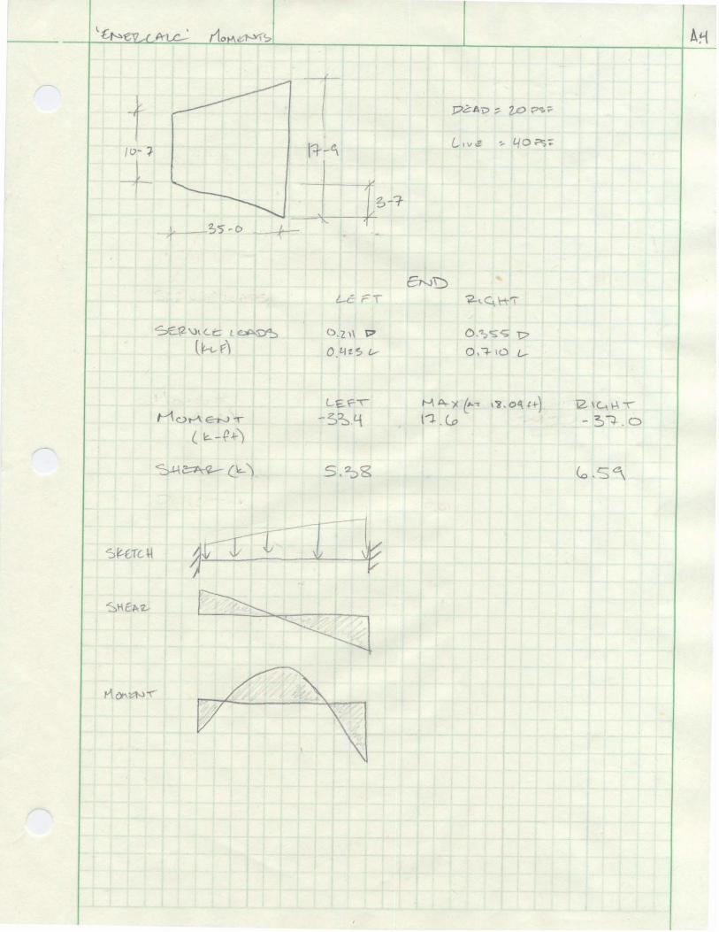
• Software o RAM Structural System o Enercalc
The alternate systems were designed with the hopes that the added columns would not disrupt the current floor plan and be small enough to fit within existing partitions. A few systems met this goal, others did not. The wall columns for this report were assumed to be replaced by a square shape and located at the perimeter. The existing wall columns are 10 inches wide and made this goal difficult to reach. Alternate system overall depths were designed attempting to match the 7.5 inch flat plate depth of the JW. Due to the reduction in spans, most systems were able to accomplish this.

4
Alternate 1: Two Way Flat Slab with Drop Panels This system uses two-way reinforced slab with drop panels only. In order to achieve an aspect ratio necessary to utilize this system two columns were added at the mid-span of the existing system (Fig. 2) and one column in the South West corner. Column capitals were not used due to higher costs. The design given in the CRSI handbook gives the minimum drop panel size per ACI 13.4.7. The larger, exterior bay governs the sizing of the slab, columns, and reinforcing. The interior bay shall be built to the specifications of the larger bay to increase constructability and form efficiency. Calculations may be found in Appendix A. Figure 3. Drop Panel Detail. Chapter 10 of the CRSI Handbook was used to determine the appropriate size, details, reinforcing, drop panels, etc. Advantages: For heavier loads and longer spans, the flat slab will require less reinforcing and concrete. The slight added cost of forming drop panels has savings over a flat plate in the amount of rebar and concrete needed. In addition smaller columns can be utilized. These designs are most efficient for bays that are square. Drop panels help to provide shear strength around the column and guard against “punching shear.” Disadvantages: Unsightly drop panels around columns have potential to disrupt interior designs and possibly even floor plans. In a bay with span of roughly 18 ft. there is not enough span to take full advantage of the cost savings when compared to a flat plate. For a live load of 50 psf or less a flat plate is only economically viable with spans between 25 and 30 ft. Formwork costs are approximately 47% of the total system cost. The addition of columns will limit partition placement and has potential to alter floor plans.
5
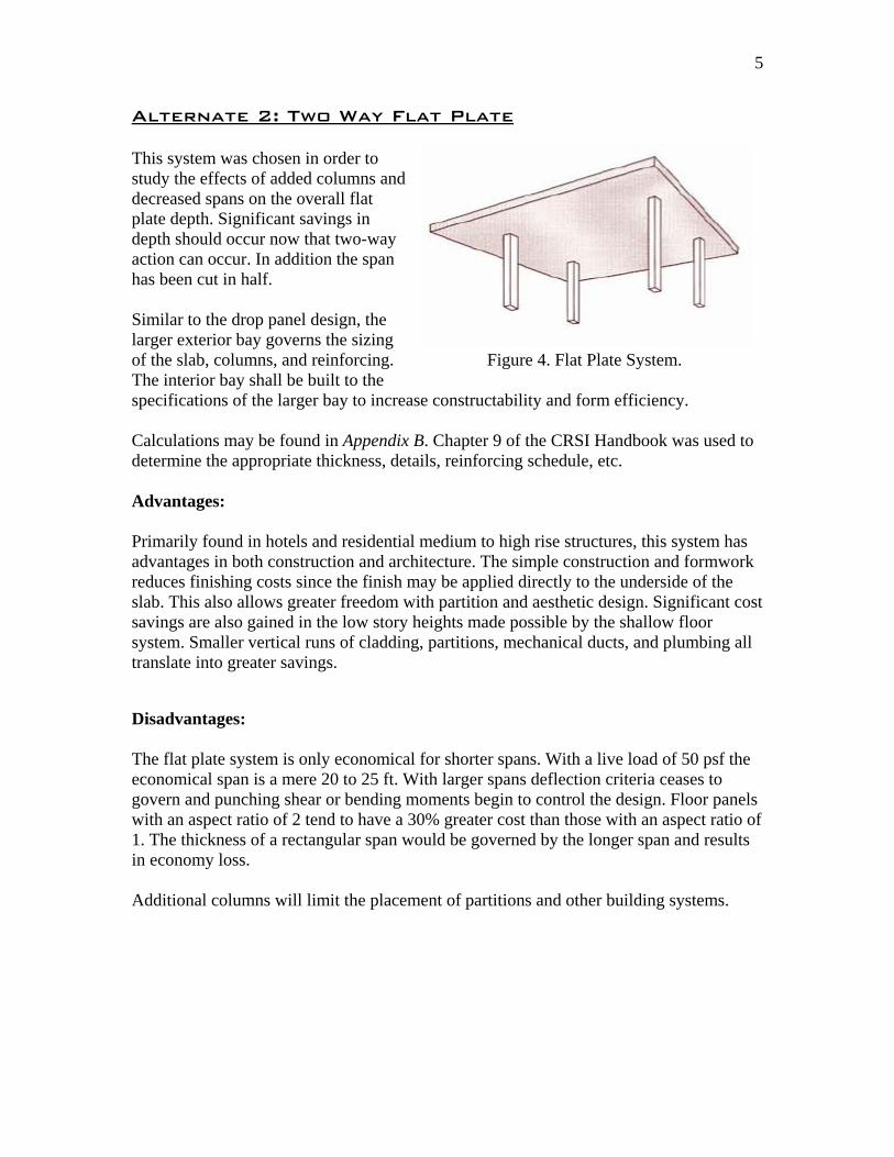
Alternate 2: Two Way Flat Plate This system was chosen in order to study the effects of added columns and decreased spans on the overall flat plate depth. Significant savings in depth should occur now that two-way action can occur. In addition the span has been cut in half. Similar to the drop panel design, the larger exterior bay governs the sizing of the slab, columns, and reinforcing. Figure 4. Flat Plate System. The interior bay shall be built to the specifications of the larger bay to increase constructability and form efficiency. Calculations may be found in Appendix B. Chapter 9 of the CRSI Handbook was used to determine the appropriate thickness, details, reinforcing schedule, etc. Advantages: Primarily found in hotels and residential medium to high rise structures, this system has advantages in both construction and architecture. The simple construction and formwork reduces finishing costs since the finish may be applied directly to the underside of the slab. This also allows greater freedom with partition and aesthetic design. Significant cost savings are also gained in the low story heights made possible by the shallow floor system. Smaller vertical runs of cladding, partitions, mechanical ducts, and plumbing all translate into greater savings. Disadvantages: The flat plate system is only economical for shorter spans. With a live load of 50 psf the economical span is a mere 20 to 25 ft. With larger spans deflection criteria ceases to govern and punching shear or bending moments begin to control the design. Floor panels with an aspect ratio of 2 tend to have a 30% greater cost than those with an aspect ratio of 1. The thickness of a rectangular span would be governed by the longer span and results in economy loss. Additional columns will limit the placement of partitions and other building systems.

6
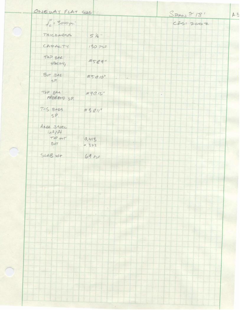
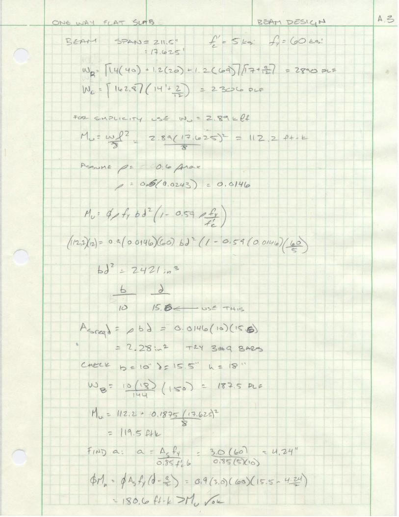
Alternate 3: One Way Flat Slab with Beams The addition of beams to the flat slab system was done in order to remove the unsightly drop panels from view of the guests. The beams shown in Figure 5 are wider than the column, but in this design it was attempted to keep the base of the beam to a maximum of 10 inches, the same width of the JW’s existing wall-columns. Savings in thickness should occur in this system due to the addition of flexural members Figure 5. Flat Slab with Beams. and shorter spans. The larger span will control the overall design of the beams and the slab in the two bays. Formwork efficiency can only be achieved if this is the case. Calculations may be found in Appendix C. Chapter 7 of the CRSI Handbook was used to determine the appropriate thickness, details, reinforcing schedule, etc. of the slab. The provisions set forth in Chapter 10 of the ACI code were used to design the beams. Advantages: The added flexural stiffness of the beams will have savings of slab depth when compared to a flat plate. Limiting the beam width to 10 inches, although not always possible, will allow the architect to hide the beams in the interior partitions of the JW. Disadvantages: The presence of beams complicates the routing mechanical ducts, plumbing systems, and limits the placing of interior partitions. The necessary formwork for the beams will slow the production schedule and add formwork, labor, and schedule costs to the project. The additional columns with further restrict the freedom of partition placement.

7
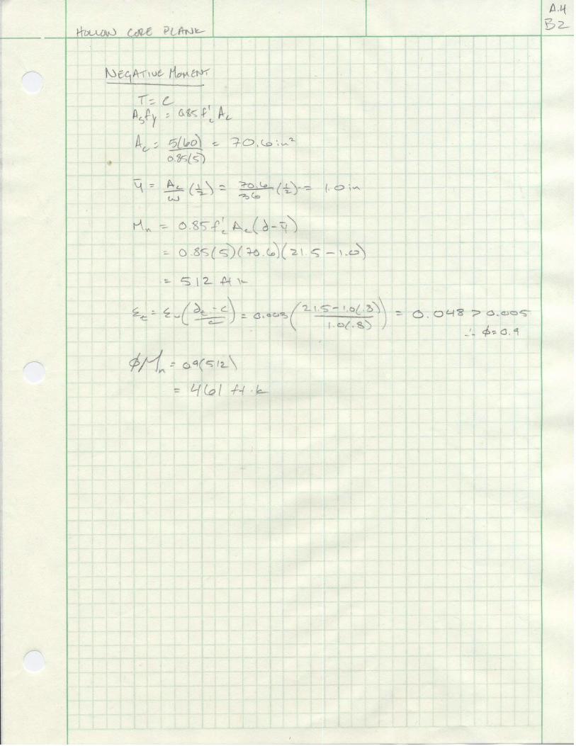
Alternate 4: Hollow Core Plank This system utilizes the same beam layout as floors 1 through 4. The addition of a column in the Southwest corner of the bay (Fig. 2) was necessary to carry out the design. Although the planks are capable of longer runs, spanning two bays for roughly 35 ft. was not reasonable due the unique shape of the JW Marriott. The larger exterior span will control the overall size of the the plank. Formwork efficiency can only be achieved Figure 6. Hollow Core Plank. if this is the case. Calculations may be found in Appendix D. Chapter 2 of the PCI Design Handbook was used to determine the appropriate thickness, details, reinforcing schedule, etc. of the slab. The provisions set forth in Chapter 10 of the ACI code were used to design the beams. Advantages: Hollow core plank provides a finished ceiling surface that can be used as installed or easily painted or sprayed to match the specifications of the architect. The plank may be drilled to install dropped ceilings, lighting, electrical, and mechanical fixtures. The hollow cores give the plank superior acoustic properties. Higher strengths, longer spans, desirable fire ratings, and increased durability may be reached due to precision casting done in a controlled environment. With no curing time, construction may continue in any weather or season. Disadvantages: The beams supporting the plank may influence partitions and building system designs. Additional formwork can be expensive and inhibit the construction schedule. This system may not be economical given the shorter spans of the JW’s typical size bay. Design changes may be hazardous with lead-in times that accompany hollow core construction. The addition of one column in the Southwest corner may disrupt partition placement.
8
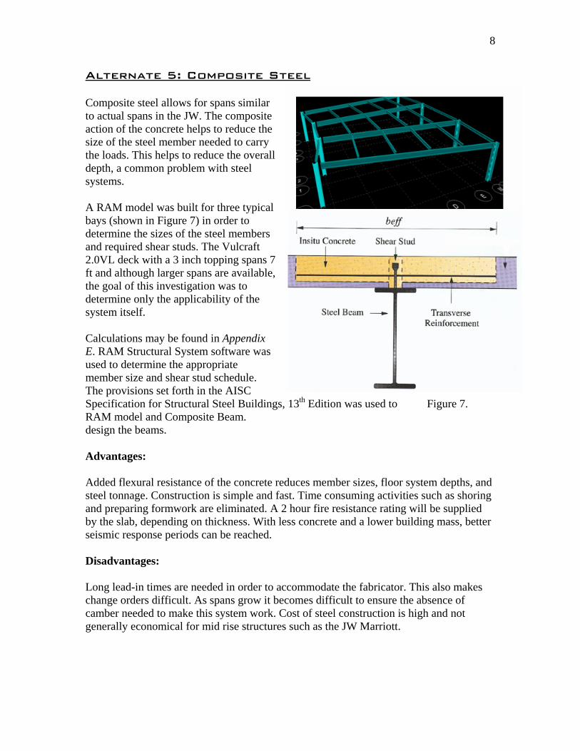
Alternate 5: Composite Steel Composite steel allows for spans similar to actual spans in the JW. The composite action of the concrete helps to reduce the size of the steel member needed to carry the loads. This helps to reduce the overall depth, a common problem with steel systems. A RAM model was built for three typical bays (shown in Figure 7) in order to determine the sizes of the steel members and required shear studs. The Vulcraft 2.0VL deck with a 3 inch topping spans 7 ft and although larger spans are available, the goal of this investigation was to determine only the applicability of the system itself. Calculations may be found in Appendix E. RAM Structural System software was used to determine the appropriate member size and shear stud schedule. The provisions set forth in the AISC Specification for Structural Steel Buildings, 13th Edition was used to Figure 7. RAM model and Composite Beam. design the beams. Advantages: Added flexural resistance of the concrete reduces member sizes, floor system depths, and steel tonnage. Construction is simple and fast. Time consuming activities such as shoring and preparing formwork are eliminated. A 2 hour fire resistance rating will be supplied by the slab, depending on thickness. With less concrete and a lower building mass, better seismic response periods can be reached. Disadvantages: Long lead-in times are needed in order to accommodate the fabricator. This also makes change orders difficult. As spans grow it becomes difficult to ensure the absence of camber needed to make this system work. Cost of steel construction is high and not generally economical for mid rise structures such as the JW Marriott.

9
Comparison and Conclusion System Existing Flat Slab w
Drop Panels 2 Way
Flat PlateFlat Slab w Beams
Hollow Core
Comp. Steel
Weight (psf)
93.75 75 93.75
68.75 74 62.5
Slab Depth (in.)
7.5 6 7.5 5.5 4 5
Largest Depth
(in.)
7.5 8.5 7.5 18 24 W16x26 d = 16.7
Column Size (in.)
10x140 12x12 10x10 10x10 24Ф W14
Construction Difficulty
Medium Medium- Hard
Medium Medium- Hard
Easy Medium
Long Lead No No No No Yes Yes Formwork Yes Yes Yes Yes No No Fire Rating
(hrs.) >2 >2 >2 >2 1-2 1.5-2
Cost per ft2
(USD)
Materials 5.45 5.75 5.45 5.30 15.60 12..25 Labor 7.20 7.55 7.20 10.00 5.55 6.45 Total 12.65 13.30 12.65 15.35 21.15 18.70
Foundation Impact
- Little- None
None Little Little-None
Yes*
Viable Alternative
- No Yes Yes No Yes
Further Study - No Yes No No Yes *Less building mass from the change to a steel system will reduce soil stresses and allow for foundation designs. Conclusion: The flat plate performs its purpose best to meet the vision of the architect. This includes unobstructed views from the guest rooms, greater license with partitions, freedom with ceiling finishes, and mechanical/electrical system routing. The high aspect ratio, >2, lends itself best to the system used. With a few of the alternate systems it is possible to limit interior partition width to the current10 inches. However the material and construction savings may not outweigh uniformity of construction and architectural costs. In addition the bay size and floor loads are not large enough to take full advantage of the two way systems investigated. The most viable alternatives are two way flat plate and composite steel, due to reduction in slab thickness and improved seismic response, respectively. Simple construction techniques and formwork drive project costs further downward with the current system. Smaller vertical runs increase economic gains with other building systems. Given the unique shape of the JW Marriott I believe that the existing floor system is the best choice.
10
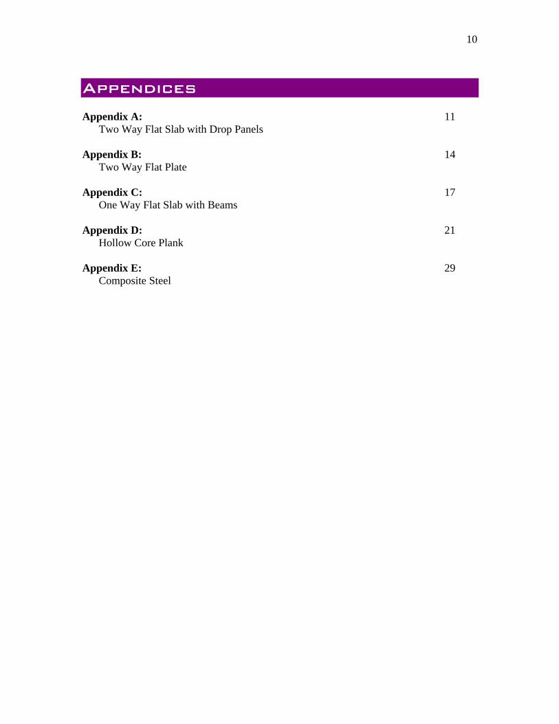
Appendices Appendix A: 11
Two Way Flat Slab with Drop Panels Appendix B: 14
Two Way Flat Plate Appendix C: 17
One Way Flat Slab with Beams Appendix D: 21
Hollow Core Plank Appendix E: 29
Composite Steel

11
Appendix A
This page is intentionally left blank.


14
Appendix B
This page is intentionally left blank.


17
Appendix C
This page is intentionally left blank.


21
Appendix D
This page is intentionally left blank.


29
Appendix E
This page is intentionally left blank.

Floor MapRAM Steel v10.0DataBase: tech 2 bay 10/25/06 21:57:24Building Code: IBC Steel Code: AISC LRFD
Floor Type: 5th floor framing
II A B C D E III F8
7
1
2
3
4
5
6W
8x10
(5)
W14x22 (20)
W8x10 (5)
W14x22 (20)W
8x10
(4)
W16x26(5) (5) (2) (6) (6)
W16x26
(5) (5) (2) (6) (6)
W8x
10 (4
)
W8x10 (5)
W8x
10 (5
)
W8x
10 (5
)
W8x10 (5)
W8x
10 (5
)
W8x
10 (5
)
W8x10 (5)
W8x
10 (5
)
W8x
10 (5
)
W8x10 (5)
W8x
10 (5
)
W8x
10 (5
)
W8x10 (5)
W8x
10 (6
)
Floor MapRAM Steel v10.0DataBase: tech 2 bay 10/25/06 21:57:24Building Code: IBC Steel Code: AISC LRFD
Decks: Deck Type OrientationVULCRAFT 2.0VL 0.00 degrees
Page 2/2

Floor MapRAM Steel v10.0DataBase: tech 2 bay 10/25/06 21:57:24Building Code: IBC Steel Code: AISC LRFD
Floor Type: 5th floor framing
II A B C D E III F8
7
1
2
3
4
5
617
18
13
155
4
2
26
22
7
25
21
8
24
20
9
23
19
10
16
14
3

Beam SummaryRAM Steel v10.0DataBase: tech 2 bay 10/25/06 21:57:24Building Code: IBC Steel Code: AISC LRFD
STEEL BEAM DESIGN SUMMARY:
Floor Type: 5th floor framing
Bm # Length +Mu -Mu Mn Fy Beam Size Studs ft kip-ft kip-ft kip-ft ksi
17 10.77 9.9 0.0 63.4 50.0 W8X10 518 35.73 173.8 0.0 259.0 50.0 W14X22 2013 10.77 9.9 0.0 63.4 50.0 W8X10 515 35.73 175.5 0.0 259.0 50.0 W14X22 205 10.31 8.8 0.0 63.3 50.0 W8X10 44 35.21 306.3 0.0 384.9 50.0 W16X26 5, 5, 2, 6, 62 35.18 307.4 0.0 384.9 50.0 W16X26 5, 5, 2, 6, 6
26 11.44 19.2 0.0 64.0 50.0 W8X10 422 11.49 19.4 0.0 64.0 50.0 W8X10 57 11.80 20.0 0.0 64.0 50.0 W8X10 5
25 12.09 21.1 0.0 64.1 50.0 W8X10 521 12.20 21.4 0.0 64.1 50.0 W8X10 58 13.29 25.4 0.0 64.1 50.0 W8X10 5
24 12.74 23.4 0.0 64.1 50.0 W8X10 520 12.90 24.0 0.0 64.1 50.0 W8X10 59 14.78 31.4 0.0 64.2 50.0 W8X10 5
23 13.39 25.9 0.0 64.1 50.0 W8X10 519 13.60 26.7 0.0 64.1 50.0 W8X10 510 16.26 38.1 0.0 64.2 50.0 W8X10 516 14.04 20.8 0.0 63.7 50.0 W8X10 514 14.31 21.6 0.0 63.7 50.0 W8X10 53 17.75 33.2 0.0 63.9 50.0 W8X10 6
* after Size denotes beam failed stress/capacity criteria.# after Size denotes beam failed deflection criteria.u after Size denotes this size has been assigned by the User.

Load DiagramRAM Steel v10.0DataBase: tech 2 bay 10/25/06 21:57:24Building Code: IBC
Floor Type: 5th floor framing Beam Number = 2Span information (ft): I-End (0.00,14.17) J-End (35.00,17.75)
W1 W2
P1P2
P3P4
Load Dist DL LL+ LL- Max Totft kips kips kips kips
P1 7.037 6.691 2.541 0.000 9.232P2 14.073 7.287 2.767 0.000 10.054P3 21.110 7.932 3.012 0.000 10.944P4 28.146 8.577 3.257 0.000 11.834
ft k/ft k/ft k/ft k/ftW1 0.000 0.056 0.011 0.000 0.067W2 35.183 0.056 0.012 0.000 0.068


