Executable UML Report - OoCities - Geocities Archive ... · EXECUTABLE UML Author : Selo Sulistyo...
24
EXECUTABLE UML Author : Selo Sulistyo and Warsun Najib Dept of Information and Communications Technology Agder University College, Norway Email : [email protected] [email protected] Abstract The history of software development is a history of raising the level of abstraction. Executable UML is at the next higher layer of abstraction, abstracting away both specific programming languages and decisions about the organization of the software so that a specification built in Executable UML can be deployed in various software environments without change. Executable UML is fundamental approach to Model Driven Architecture, MDA, a new way of writing specifications and developing applications, based on a platform-independent model (PIM). This paper is a rapport of our case studies how Executable UML tool can be used to develop software system. 1. Introduction The history of software development is a history of raising the level of abstraction. In the beginning of software engineering, many industries used to build systems by soldering wires together to form hard-wired programs. Now we have languages such as Smalltalk, C++, Eiffel, and Java, each with the notion of object-orientation, an approach for structuring data and behavior together into classes and objects. And as we moved from one language to another, generally we increased the level of abstraction at which the developer operates, requiring the developer to learn a new higher-level language that may then be mapped into lower-level ones, from C++ to C to assembly code to machine code and the hardware As the profession has raised the level of abstraction at which developers work, software developers have developed tools to map from one layer to the next automatically. Developers now write in a high- level language that can be mapped to a lower-level language automatically, instead of writing in the lower level language that can be mapped to assembly language, just as our predecessors wrote in assembly language and translated that automatically into machine language. "Executable UML models systems at a higher level of abstraction, avoiding the costs involved in a premature design," reports Steve Mellor of Project Tech. "It also offers the benefits of early verification through simulation, the ability to translate the UML model directly into efficient code, and the ability to delay implementation decisions until the last minute. 2. Executable UML The UML provides many ways of representing aspects of software and systems. Some of the notations provide alternative ways of representing the same concepts with a different emphasis. Users of the UML have to select which elements to use and to decide how to use them. In addition, not all aspects of the UML are fully defined, for example what is the behaviour implied by a return action? Executable UML seeks to define, precisely, the execution semantics of the relevant elements of the UML. The benefits of this are many-fold: • The UML models can be unambiguously interpreted, which at the very helps the human reader; • The UML models can be executed, which, given a suitable environment, means that they can be validated early in the development lifecycle;
Transcript of Executable UML Report - OoCities - Geocities Archive ... · EXECUTABLE UML Author : Selo Sulistyo...

EXECUTABLE UML
Author : Selo Sulistyo and Warsun Najib
Dept of Information and Communications Technology Agder University College, Norway
Email : [email protected] [email protected]
Abstract
The history of software development is a history of raising the level of abstraction. Executable UML is at the next higher layer of abstraction, abstracting away both specific programming languages and decisions about the organization of the software so that a specification built in Executable UML can be deployed in various software environments without change. Executable UML is fundamental approach to Model Driven Architecture, MDA, a new way of writing specifications and developing applications, based on a platform-independent model (PIM). This paper is a rapport of our case studies how Executable UML tool can be used to develop software system.
1. Introduction
The history of software development is a history of raising the level of abstraction. In the beginning of software engineering, many industries used to build systems by soldering wires together to form hard-wired programs. Now we have languages such as Smalltalk, C++, Eiffel, and Java, each with the notion of object-orientation, an approach for structuring data and behavior together into classes and objects. And as we moved from one language to another, generally we increased the level of abstraction at which the developer operates, requiring the developer to learn a new higher-level language that may then be mapped into lower-level ones, from C++ to C to assembly code to machine code and the hardware
As the profession has raised the level of abstraction at which developers work, software developers
have developed tools to map from one layer to the next automatically. Developers now write in a high-level language that can be mapped to a lower-level language automatically, instead of writing in the lower level language that can be mapped to assembly language, just as our predecessors wrote in assembly language and translated that automatically into machine language.
"Executable UML models systems at a higher level of abstraction, avoiding the costs involved in a
premature design," reports Steve Mellor of Project Tech. "It also offers the benefits of early verification through simulation, the ability to translate the UML model directly into efficient code, and the ability to delay implementation decisions until the last minute.
2. Executable UML
The UML provides many ways of representing aspects of software and systems. Some of the notations provide alternative ways of representing the same concepts with a different emphasis. Users of the UML have to select which elements to use and to decide how to use them. In addition, not all aspects of the UML are fully defined, for example what is the behaviour implied by a return action? Executable UML seeks to define, precisely, the execution semantics of the relevant elements of the UML. The benefits of this are many-fold:
• The UML models can be unambiguously interpreted, which at the very helps the human reader;
• The UML models can be executed, which, given a suitable environment, means that they can be validated early in the development lifecycle;

2
• The UML models can be translated to target code achieving 100% code generation; • The UML models can potentially be translated to silicon; • The UML becomes a very high level language
Executable UML is a profile of the Unified Modeling Language with defined semantics for both the
components and the interactions between them during execution. The UML was originally designed to sketch the structure of object-oriented software systems.
Consequently, it contains elements designed to map closely to software concepts such as class, task, parameter and so on. Given this sketch of the software, a designer/programmer can then fill in the details in the selected programming language to complete the system. In this view, there is little purpose in defining the details of actions closely-they might just as well be programmed directly.
The UML can also be used to model the structure of a solution quite independent of the structure of
the software. In this context, a class is a packaging of information and behavior which could be rendered in any form, perhaps a class in an object-oriented programming language, a block of data and a set of functions in a traditional programming language, or even in hardware. The concept of a task is an implementation structure which has no place in a model of a solution. Consequently, executable UML is a subset of UML proper. On the other hand, to be useful, this subset of UML must have a way to specify actions at a higher level of abstraction than a programming language.
There are many executable profiles that could be defined to select a set of meaningful components
and how they interact during execution. For example, a object can invoke methods of other objects, which in turn invoke more methods, all in a completely synchronous environment. Only one thing happens at a time (the currently executing method) and the concept of a state machine is useful only as way to state constraints on the order of method execution.
The first profile defined for executable UML is one based on state charts and asynchronous,
distributed behavior. Each object has a state machine that executes independently of all others. It is in just one state at a time, possibly executing many actions. It can invoke data access methods (that do not change state) synchronously, and it can send asynchronous signal events to communicate and synchronize with other independently executing state charts. Both these elements and the interactions between them have a precise definition at run-time-sufficiently well-defined, in fact, to be executable, and translatable into multiple possible implementations. A model built in executable UML is therefore independent of software organization and implementation decisions: It is software-platform independent.
2.1. Executable UML Tool
There are many research groups that propose and develop an executable UML tool. Three of them are iUML (intelligent UML) from Kennedy Carter 1), Kabira from Kabira Design Center2) and BridgePoint Development Suite from Project Technology3) that has Automated Support for Executable and Translatable UML. Unfortunately, all of them are not full free distributed. One of the executable UML tools that limited distributed is iUMLite from Kennedy Carter, as a free version of iUML.
Some other tools that have related to UML and its code generation (code generator) are
UML2EJB4) from Sourceforge.net that can generate the EJB code from UML, WMEE5) from Sygel that can used to build J2EE applications from UML.
Beside executable UML and Code Generator, there are also exist other simulator for UML such
as UMLAUT software from IRISA in France6) and Prosasim from Insof Finland7)
2.2. Action Language
The Action Semantics aims at providing modelers with a complete, software-independent specification for actions in their models. The goal is to make UML modeling executable modeling,

3
i.e. to allow designers to test and verify early and to generate 100% of the code if desired. It builds on the foundations of existing industrial practices such as SDL, Kennedy Carter or BridgePoint action languages.
Traditional modeling methods which do not have support for any action language have focused
on separating analysis and design, i.e. the what the system has to do and the how that will be achieved. While this separation clearly has some benefits, such as allowing the designer to focus on system requirements without spreading himself/herself too thinly with implementation details, or allowing the reuse of the same analysis model for different implementations, it also has numerous drawbacks. The main one is that this distinction is a difficult, not to say impossible, one to make in practice: the boundaries are vague; there are no criteria for deciding what analysis is, and what is not. Rejecting some aspects from analysis make it incomplete and imprecise; trying to complete it often obliges the introduction of some how issues for describing the most complex behavior.
As described above, the complete UML specification of a model relies on the use of un-
interpreted entities, with no well-defined and accepted common formalism and semantics. This may be, for example, guards on transitions specified with the Object Constraint Language (OCL), actions in states specified in Java or C++.
In the worst case, that is for most of the modeling tools, these statements are simply inserted at
the right place into the code skeleton. The semantics of execution is then given by the specification of the programming language. Unfortunately, this often implies an over-specification of the problem, for example in Java, a sequential execution of the statements of a method is supposed), verification and testing are feasible only when the code is available, far too late in the development process. Moreover, the designer must have some knowledge of the way the code is generated for the whole model in order to have a good understanding of the implications of her inserted code.
At best, the modeling tool has its own action language and then the model may be executed and
simulated in the early development phases, but with the drawbacks of no standardization, no interoperability, and two formalisms for the modeler to learn (the UML and the action language).
The Action Semantics provides designers with an expressive formalism for writing model
transformations in an operational way, and a model for UML statement execution that fills some semantic gaps in the behavior aspects of a UML model. Moreover, since the UML metamodel itself is a UML model, the Action Semantics can be used as a powerful mechanism for meta-programming. This particularity opens new perspectives for designers, compared to other model manipulations languages (e.g. J or Visual Basic), thanks to its perfect integration with the UML: all the features of the UML, such as constraints (pre or post-conditions, invariants), refinements or traces can be applied within the Action Semantics.
2.3. Executable UML by Kennedy Carter
xUML is a sub-set of the Unified Modeling Language incorporating a complete Action Language that allows system developers to build executable system models and then use these models to produce high quality code for their target systems.
xUML is an executable version of the UML, with
• Clearly defined simple model structure • A precise semantics for actions, which will be incorporated into the UML standard • A compliant action specification language • An accompanying process
xUML is a proven development process, oriented towards… • Executable modeling • Large-scale reuse • Pattern based design
Kennedy Carter defines that xUML as UML1.4 minus semantically weakness plus precisely
Defined action semantics as shows in the following figure:

4
Figure 1 xUML, an executable UML version by Kennedy Carter
The designers of UML did not intend that developers would use all the formalism at any one time. Rather, they intended it to support a particular paradigm for a particular type of development.
xUML has no hierarchical notations. It is just model layer as shown in the following figure.
Figure 2 xUML notation
2.3.1. Action Specific Language, ASL The Action Specification Language (ASL), which is an UML semantic language defined by
Kennedy Carter, is an implementation independent language for specifying processing in the methods and state actions of object models. The language has been placed in the public domain and may be freely used by analysts and developers. The translation techniques used range from fully automatic generation to manual coding using a defined set of rules. Target languages have included C, C++, Objective C, Java, FORTRAN, SQL and proprietary languages.
The ASL definition is independent of any particular implementation. Potential users should
therefore check carefully the level of support offered by any particular CASE tool or code generator, before embarking on large-scale use of the language.
• ASL is a language providing: • Sequential Logic • Access to the data described by the Class Diagram • Access to the data supplied by signals initiating actions • The ability to generate signals • Access to timers • Access to synchronous operations provided by classes and objects • Access to operations provided by other domains • Tests and Transformations
UML V1.4
xUML = Precisely Defined Action Semantics + Semantically
Weak Elements -
Calendar
User Interface
Domains
Event Calendar
EventIDDescription Time Date Location
UserUserName UserID Email AddUserList deleUser(user)
01
1
R2
Classes
2. Add Program entry/ evt = create Event Calender with \ EventID=1 Description=”Seminar xUML” Time= 11.30 Date=2002.11.22 Location=”HiA”
States
Operations
AddUser(UserName,UserID,Email)

5
This processing can, in principle, execute at the same time as processing associated with another state machine. In xUML ASL segments can be used to define:
• The processing to be carried out on entry to a state • The processing to be carried out by a method behind an operation • The startup sequence for a system either for test or for target system purposes • The processing to be carried out by test methods for simulation purposes • The processing to be executed in bridges providing the mapping between domains
Figure 3 xUML based development [Kennedy Carter]
2.3.2. Executable UML Based Development There are three phases in developing a model with xUML:
a. Preparation or Inception Phase As a preparation phase, this phase does not produce any executable models but
provides the foundation for the next phase. This phase aim is to establish requirement and scope:
• scope the project • capture requirement with uses cases • partition the system into domains • identity new, reused or COTS domains • produce first-cut class and interaction diagram for new domains • identify key risk • produce size and cost estimates
b. Modeling or Elaboration Phase
In this phase, executable modeling is ideal for iterative and incremental development which each of iteration takes form:
• Update the domain interaction diagram if necessary • For each domain involved: • Produce the class collaboration diagram • Produce state models for classes • Update the class diagram as required • Add operation to the classes • Specify the operations and state actions with action language • Specify initial conditions and test methods with an action language • Specify the provided and required interface of the domain • Build the domain model • Simulate the scenario through the domain
Design
Design Patterns
Small team oftechnology
experts
the“software
architectur
Implement
Software System
Automatically in minutes or hours
Analyse
xUML Model
Complete, Precise &
testable
small teams of application experts

6
• Specify the bridge which connect the domains • Build the multi domain model • Simulate the scenario through all involved domains
c. Construction Phase Manual or automatic application of abstract design rules to application models.
2.3.3. Executable UML Process The xUML process is a rigorous object-oriented system development method based upon
experience with executable modeling that has been applied to many pioneering projects in sectors such as telecommunications, automotive, aerospace and defense.
It is based upon the principle of building a set of precise, testable analysis models of the system to be developed, executing defined tests on these models, and defining a systematic strategy by which the models will be used to produce code for the desired target system. The xUML process embodies these distinctive characteristics:
• Precise, Complete Analysis Models, that can be subjected to rigorous testing by simulation. Thus xUML provides a strong analysis completion criterion, which is: “The analysis model is complete when it delivers the expected results for all test cases.”
• Simple Notations, using the Unified Modeling Language organized into a coherent set of layers. This means that normal human beings, such as customers, hardware engineers and managers can read, understand and provide helpful feedback on the emerging analysis models.
• An Understandable and Repeatable Partitioning Strategy, based upon the idea of Separation of Subject Matters. This means that both small and large system development projects can be partitioned in a way that avoids, for example, fruitless arguments about what constitutes analysis and what constitutes design.
• A Conceptually Coherent Process, that provides a small but sufficient set of techniques to address all subject matters, including “design”, in a uniform way.
• Useable Analysis Models, which can be used by system designers and coders without the need for unreliable “interpretation” of the meaning of the models.
• Implementation by Translation, in which the entire system can, if desired, can be automatically, generated from the analysis models, using a set of rigorously specified rules that deliver a system with the required performance characteristics.
• Large-Scale Reuse, in which entire sets of objects are reused as a single component.
Figure 4 xUML process [Kennedy Carter]
ANALYSE NEW DOMAINS
Build Static Model Build Dynamic Models
Specify Actions Model domain use cases
Execute and debug xUML models
PRODUCE TARGET CODE
Apply design patterns to xUML models
Perform target testing
SPECIFY DOMAINS Identify new/reused domains
Model system use cases
VALIDATE ANALYSIS
Execute domain use cases Execute system use cases
FORMALISE ABSTRACT DESIGN MODEL
Select or develop suitable patterns
and mechanisms
(Build/Buy xUML compiler)
7
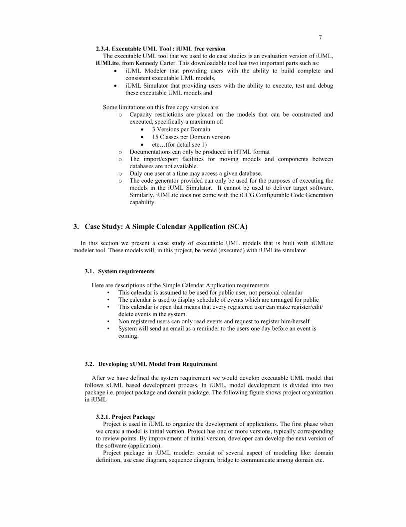
2.3.4. Executable UML Tool : iUML free version The executable UML tool that we used to do case studies is an evaluation version of iUML,
iUMLite, from Kennedy Carter. This downloadable tool has two important parts such as: • iUML Modeler that providing users with the ability to build complete and
consistent executable UML models, • iUML Simulator that providing users with the ability to execute, test and debug
these executable UML models and Some limitations on this free copy version are:
o Capacity restrictions are placed on the models that can be constructed and executed, specifically a maximum of:
• 3 Versions per Domain • 15 Classes per Domain version • etc…(for detail see 1)
o Documentations can only be produced in HTML format o The import/export facilities for moving models and components between
databases are not available. o Only one user at a time may access a given database. o The code generator provided can only be used for the purposes of executing the
models in the iUML Simulator. It cannot be used to deliver target software. Similarly, iUMLite does not come with the iCCG Configurable Code Generation capability.
3. Case Study: A Simple Calendar Application (SCA)
In this section we present a case study of executable UML models that is built with iUMLite modeler tool. These models will, in this project, be tested (executed) with iUMLite simulator.
3.1. System requirements
Here are descriptions of the Simple Calendar Application requirements • This calendar is assumed to be used for public user, not personal calendar • The calendar is used to display schedule of events which are arranged for public • This calendar is open that means that every registered user can make register/edit/
delete events in the system. • Non registered users can only read events and request to register him/herself • System will send an email as a reminder to the users one day before an event is
coming.
3.2. Developing xUML Model from Requirement
After we have defined the system requirement we would develop executable UML model that follows xUML based development process. In iUML, model development is divided into two package i.e. project package and domain package. The following figure shows project organization in iUML
3.2.1. Project Package Project is used in iUML to organize the development of applications. The first phase when
we create a model is initial version. Project has one or more versions, typically corresponding to review points. By improvement of initial version, developer can develop the next version of the software (application).
Project package in iUML modeler consist of several aspect of modeling like: domain definition, use case diagram, sequence diagram, bridge to communicate among domain etc.

8
Figure 5 Project Organization in iUML
3.2.1.1. Use Case Diagram A good place to start when analyzing the Simple Calendar Application system is to
consider the things we would expect to do with the system. In xUML, Use Cases describe the ways the system can be used. It is a “black box” view of required functionality of the system.
An actor, in this case is users, is an external entity that interacts with the system by invoking the behavior described by the Use Cases. An actor may represent a role performed by a person (note that a single person may perform many roles). In this application, a user can add, modify or delete an event to/from database of the system. A user can also register himself as new user in database of application..
Figure 6 SCA use case diagram
3.2.1.2. Domain Partitioning In xUML, the system being analyzed is separated into subject matters called domains. The
domains are captured as individual xUML models, each of which addresses one subject matter only, and is uncontaminated by knowledge of other system aspects. This results in components that are exceptionally reusable.

9
In this Calendar Application we have created three domains i.e. Calendar, Email Agent and User Interface domains as shown in the following figure.
Figure 7 SCA Domain model
3.2.1.3. Sequence Diagram
Figure 8 Sequence diagram for add new event Domain Interaction Analysis is a complimentary technique which allows the project team
to analyze the dynamics of the complete system of domains. iUML supports this approach through the provision of Sequence Diagrams. Sequence Diagrams bring together the work already done on Use Cases and Domain Partitioning. Using the sequence diagram the analyst models the interactions between selected domains necessary to provide the behavior specified in a particular Use Case. Sequence Diagrams provide a powerful modeling technique with the following benefits:
o Early exploration of the dynamic interactions between domains. o Reduced risk of incorrect domain partitioning o Provides traceability from use cases to domain models o Leads to the definition of the provided and required interfaces for each domain o Documents the system design by answering the question ‘how does the system
do this?’ o Forms the basis for planning Multi-Domain Simulation and Integration testing
Figure 8 depicts one of some sequence diagrams that we have developed for Calendar Application. This example shows sequence diagram when a user wants to add new event into system.

10
3.2.2. Static Modeling in Domain Package The purpose of the Static Model is to describe the state of the problem domain at any point
in time. The data described by the model will change over time as the system executes. A static model is represented on a Class Diagram which is enhanced with supportive descriptions and data definitions. By contrast, the Dynamic model describes the events and operations which will cause the data described in the static model to change.
Each of the Domains on the Domain model will require a corresponding Domain within the database in which the analysis can be conducted - as such we will be required to create one or more domains to the database.
In this case study the ‘Calendar’ domain will be created to the database corresponding with this domain that has been identified on the Domain model in the project package development.
3.2.2.1. Class Diagram The first stage of editing the static model involves adding classes to the Class Diagram and
the associations between them. A Class Diagram depicts the classes in the domain. Classes represent the conceptual entities which make up the subject matter under consideration. They each possess pertinent characteristics, which are depicted as Attributes, and they participate in relevant associations, which are depicted as links between the classes.
In this project we have defined four classes in “Calendar” domain as follow: o Event Calendar o User o Calendar User Interface o Reminder
Figure 9 SCA Class Diagram
3.2.2.2. Attributes Attributes describe the characteristics of a class in the ‘real world’. Each characteristic is
represented as an attribute, for example, the Event Calendar Class will have these attributes: event ID, description, time, date and location.
Often there is more than one way of identifying a instance of a class. iUML thus allows the definition of multiple alternative identifiers. Of these, one is always designated as the "Preferred" by the analyst. The preferred identifier is presented by default on some model views. Such identifiers are also used by iUML to “formalize” associations by the automatic creation of Referential Attributes in associated classes. Such attributes serve to further emphasize the nature of an association either by renaming of them or by merging of them with other referential attributes.

11
3.2.2.3. Associations So far we have defined the 'information' relating to the domain in terms of classes and
attributes. The relationships between the classes are equally important since these provide information about the way objects of the classes (objects) are related to one another. Such relationships are modeled as Associations between the respective classes. For example there is an association between Event Calendar and User. A user have zero or more event calendar..
Every association has a unique association number which is automatically assigned by iUML. At each end, the association has: a. A role phrase: Every association has a pair of role phrases, indicating the meaning of the
association from each class’s point of view. b. Multiplicity: Each end of an association has a multiplicity string indicating how many
objects of one class can participate with respect to a single object of the other class. After we define all class with its attributes and operation we have the following class
diagram
3.2.3. Class Collaboration Diagrams Now we move from static modeling to dynamic modeling, but before specifying class
behavior in detail, it is important to establish: • The primary responsibilities of each class. • The interface provided by each class. • The way in which the classes will interact.
This is achieved by building the Class Collaboration Diagram. This provides a graphical
summary of all the interactions between the classes. The interactions will be in one of two forms:
• Asynchronous Interactions: These are modeled using Signal Transmissions. • Synchronous Interactions: These are modeled with Operation Invocations.
The behaviors of a class may be defined as:
• State Dependent: Where the class behaviors exhibits a ‘life cycle’ form which is defined in a State Machine. It is this state machine that defines the responses to the respective Asynchronous Interactions. In the case study, Tank, Pump, Delivery and Transaction, have state dependant behavior.
• State Independent: The classes’ behavior is expressed as a set of provided operations (analogous to a function/procedure/subroutine in most programming languages). It is these services that define the responses to the respective synchronous interactions.
The Class Collaboration Diagram summarizes the interactions in terms of:
• A class as defined in class diagram • A Terminator - This is an abstraction of something outside a domain. An
example for terminator is User Command (see figure below) • A half arrow head represents an asynchronous Signal Transmission from one
state machine to another. All interaction in Calendar Application are in the form of signal transmission. We do not define operation.
• A full arrow head represents an operation invocation. Note that the direction of the arrowhead reflects the invocation direction, not the data flow.

12
Figure 10 Class Collaboration Diagram Each class in the domain can have one object state machine. Some association classes may
also have an “assigner state machine”. The Dynamic Model outlines the behavior of the system in response to signals and
invocations. The Dynamic Model models real world policies and behavior, moving closer to the implementation of domain requirements.
The modeling components for a dynamic model are State Machines, Signals and Operations. These components are represented on Class Diagrams (operations), the Class Collaboration Diagram, State Charts, State Tables and Sequence Diagrams.
3.2.4. State Machine The Class Collaboration Diagram provides a graphical representation of the interactions
between the classes in a domain, in terms of the operation invocations and signal transmissions. The Class Collaboration Diagram only provides a black box view of the classes. The State Machine provides a representation of the way in which each class responds to signals. The State Machine is therefore a white box view of the state dependant interface of a class.
In the Calendar domain, classes such as Event Calendar, User, and User Interface have interesting life cycles consisting of states and transitions between these states.
These life cycles are modeled using State Machines. In iUML they can be represented in two forms: • The State Chart
The State Chart provides a clear graphical representation of the state machine. It enables you to see clearly the sequences and cycles of a class.
• The State Table The State Chart does not require addressing every possible combination of state and
signal. The tabular representation of the state machine used for the State Table supports the complete specification of the state machine. In the State Table, each row corresponds to a state, each column corresponds to a signal and each cell represents a potential transition. These cells are referred to as effects.

13
Figure 11 State Machine for User Interface Class
3.3. Test Methods
The executable UML model that has built with iUML modeler will be tested (executed) with iUML simulator to see behavior of the model. In order to test the model, it needs to define initialization-segment and several test methods. We have defined the following segment code with ASL semantic.
o Initialization o Add New User o Delete User o Add Event o Delete Event o Display All Event
Initialization code is defined by ASL semantic that follows the iUML software. Detail of ASL
code for initialization and all test methods could be seen in appendix. Test method is used when we simulate model to give stimulus that represent interaction with user, into application.
3.4. Test Results with iUML Simulator
Detail simulation result of the model given in appendix. The figure below depicts one of table resulted by simulator that shows object of “Event Calendar” Class.
Figure 12 Simulation result shows object of the Event Calendar Class

14
3.5. Code Generation
Evaluation copy of iUML tool can only generate code (execute model) into simulator. But in full version it capable to generate into executable application. Simulation of the executable UML domain is achieved by translating the model into code, compiling it and then executing it within a simulation environment. This enables model’s behaviour to be verified. In iUML tool, this is done in the following steps:
o Writing the domain to the build area (directory where code generation takes place) o Building the simulation executable. This involves translating the model into code and
then compiling and linking it to generate the executable. o Executing the model using iUML simulator. Simulation include ability to set
breakpoint, stimulate the model, and browse the object and local variable. List of files generated by code generation can be seen in appendix.
4. Future Work : MDA
Defining a mapping from the rigorously defined PIM (expressed in xUML) to the implementation is what is at the heart of xMDA. Since xUML models are executable and rigorous they act as much more than a simple agenda for the software developer, they actually embody in the business logic required to execute and verify the system.
It is interest to study the possibility of transforming an existing UML model to a Platform
Independent Model (PIM) and reverse engineering of components specified by IDL interfaces to a MDA context
5. Conclusion
Benefits of design with executable UML to develop software system are: 1. The modeling notations are simple and precise that makes them easier to learn and use
effectively. 2. The xUML models can be tested at the earliest opportunity by executing them in the
iUML simulation environment that reduces risk and cuts development costs. 3. The xUML modelers are isolated from the software detail and so can concentrate on a
through exploration of the problem space. 4. The xUML models can be translated directly to code that follows shortens development
time and eliminates redundancy in analysis and design models. 5. Executable models support the MDA approach in two ways. First, they allow early
testing using simulation and debug tools and secondly, since they are full and formal specification of the system behavior, they allow generation of the target code.
6. Literatures
1. www.kc.com, kennedy carter’s website. 2. www.kabira.com 3. www.projtech.com 4. www.sygel.com 5. www.irisa.fr 6. www.prosa.fi 7. Mellor, S.J. , 2002, Executable UML A foundation for Model Driven Architecture 8. Starr, L, 2002 Executable UML How to Build Class Models, Prentice Hall PTR 9. www.umlactionsemantics.org 10. www.omg.org/mda.

1
Appendix: Documentations
1 Model
1.1 Use Case Model
Figure A.1 Use Case Model
1.2 Domain Model
Figure A.2 Domain Model
1.3 Sequence Diagram
Figure A.3 Sequence diagram : Add New Event Calendar.

2
Figure A.4 Sequence diagram : Add New User
Figure A.5 Sequence diagram : Delete Event Calendar
Figure A.6 Sequence diagram : Display All Event Calendar

3
Figure A.7 Sequence diagram : Modify Event Calendar
1.4 Class Diagram
Figure A.8 Class diagram

4
1.5 State Machine 1.5.1 State Machine for Calendar User Interface Class
Figure A.9 State machine for Calendar User Interface Class. 1.5.2 State Machine for Event Calendar Class
Figure A.10 State machine for Event Calendar Class

5
1.5.3 State Machine for User Class
Figure A.11 State machine for User Class

6
2 ASL Code
2.1 Initialization
# Initialization segment, create objects (instance handle) of # user interface, event calender and user ui = create Calendar_User_Interface ui.Current_State = 'Waiting_Command' event101 = create Event_Calender with \ EventID = 101 & \ Description = "Seminar XUML" & \ Time = "09:30 - 14.00 " & \ Dato = "10.01.2003" & \ Location = "Grimstadl" event102 = create Event_Calender with \ EventID = 102 & \ Description = "Painting Exhibition" & \ Time = "10:00 - 14.00" & \ Dato = "01.01.2003 - 05.01.2003" & \ Location = "Kristiansand" user1 = create User with \ UserID = 101 & \ Name = "Hilde Osdal" & \ Email = "[email protected]" user2 = create User with \ UserID = 102 & \ Name = "Stein Kristiansen" & \ Email = "[email protected]" link user1 R1 event101 link user2 R1 event102
2.2 Test Methods
2.2.1 Add New Event Calendar # Test method for add new event calender ui = find-one Calendar_User_Interface where Current_State = 'Waiting_Command' EventID = 103 Description = "Seminar XMI" Time = "09:30 - 15:00" Dato = "11.10.2002" Location = "HIO" generate UI1:Add_Program(EventID,Description,Time,Dato,Location) to ui
2.2.2 Delete Event
# Test method for delete an event Assume that event will # be deleted is event with EventID = 101 ui = find-one Calendar_User_Interface where Current_State = 'Waiting_Command' delevent = 101 generate UI5:Delete_Event(delevent) to ui

7
2.2.3 Add New User
# Test method add new user ui = find-one Calendar_User_Interface where Current_State = 'Waiting_Command' UserID = 103 Name = "Signe Lovdal" Email = "[email protected]" generate UI2:Add_User(UserID,Name,Email) to ui
2.2.4 Delete User
# Deleting a User which have UserID = 102 ui = find-one Calendar_User_Interface where Current_State = 'Waiting_Command' deluser = 102 generate UI4:Delete_User(deluser) to ui
2.2.5 Display All Event # Test method for displaying all program ui = find-one Calendar_User_Interface where Current_State = 'Waiting_Command' generate UI6:Display_All_Event() to ui
3 Simulation
Figure A.12 Simulator window while first opened.
This window shows ASL code of initialization segment

8
Figure A.13 Table consist of objects of Event Calendar Class
Figure A.14 User object defined by initialization
Figure A.15 Simulator window shows loaded test method for Add New Event

9
Figure A.16 Table of Event Calendar objects after execute “Add New Event” test method
4 Calendar Application Files Generated by Code Generation in iUMLite
Figure A.17 List of files generated by code generation

10
5 Documentation Generated by iUMLite
Executable UML tools like iUML has ability to generate documentation in several format i.e. html, postscript, ASCII text, Groff and Frame Maker. But unfortunately, in evaluation version it can only generate documentation in html format. Here are two of documentations that follow this report.
• Use Case Analysis Report • Domain Notebook