Excalibur Bus Functional Model User Guide - Altera · The bus functional model interprets a file of...
32
UG-XBUS-1.2 Bus Functional Model Excalibur 101 Innovation Drive San Jose, CA 95134 (408) 544-7000 http://www.altera.com User Guide July 2002 Version 1.2
Transcript of Excalibur Bus Functional Model User Guide - Altera · The bus functional model interprets a file of...
UG-XBUS-1.2
Bus Functional Model
Excalibur
101 Innovation DriveSan Jose, CA 95134(408) 544-7000http://www.altera.com
User GuideJuly 2002
Version 1.2

ii Altera Corporation
Excalibur Bus Functional Model User Guide
Copyright 2002 Altera Corporation. Altera, The Programmable Solutions Company, the stylized Altera logo, specific device designations, and allother words and logos that are identified as trademarks and/or service marks are, unless noted otherwise, the trademarks and service marks of AlteraCorporation in the U.S. and other countries. All other product or service names are the property of their respective holders. Alteraproducts are protected under numerous U.S. and foreign patents and pending applications, mask work rights, and copyrights.Altera warrants performance of its semiconductor products to current specifications in accordance with Altera’s standard warranty,but reserves the right to make changes to any products and services at any time without notice. Altera assumes no responsibility orliability arising out of the application or use of any information, product, or service described herein except as expressly agreed toin writing by Altera Corporation. Altera customers are advised to obtain the latest version of device specifications before relying onany published information and before placing orders for products or services. All rights reserved.
User Guide
About this User Guide
This user guide provides comprehensive information about the Altera® Excalibur™ bus functional model.
Table 1 shows the user guide revision history.
How to Find Information
� The Adobe Acrobat Find feature allows you to search the contents of a PDF file. Click on the binoculars icon in the top toolbar to open the Find dialog box.
� Bookmarks serve as an additional table of contents.� Thumbnail icons, which provide miniature previews of each page,
provide a link to the pages.� Numerous links, shown in green text, allow you to jump to related
information.
Table 1. Revision History
Revision Date Description
1.2 July 2002 Minor changes to text; plus modifications to Appendix A for additional command types and examples
1.1 January 2002 Changes to introduction
1.0 January 2001 Initial publication
Altera Corporation iii

About this User Guide Excalibur Bus Functional Model User Guide
How to Contact Altera
For the most up-to-date information about Altera products, go to the Altera world-wide web site at http://www.altera.com.
For additional information about Altera products, consult the sources shown in Table 2.
Note:(1) You can also contact your local Altera sales office or sales representative.
Table 2. How to Contact Altera
Information Type USA & Canada All Other Locations
Product literature http://www.altera.com http://www.altera.com
Altera literature services [email protected] (1) [email protected] (1)
Non-technical customer service
(800) 767-3753 (408) 544-7000 (7:30 a.m. to 5:30 p.m. Pacific Time)
Technical support (800) 800-EPLD (3753)(7:30 a.m. to 5:30 p.m. Pacific Time)
(408) 544-7000 (1)(7:30 a.m. to 5:30 p.m. Pacific Time)
http://www.altera.com/mysupport/ http://www.altera.com/mysupport/
FTP site ftp.altera.com ftp.altera.com
iv Altera Corporation
Excalibur Bus Functional Model User Guide About this User Guide
Typographic Conventions
The Excalibur Bus Functional Model User Guide uses the typographic conventions shown in Table 3.
Table 3. Conventions
Visual Cue Meaning
Bold Type with Initial Capital Letters
Command names, dialog box titles, checkbox options, and dialog box options are shown in bold, initial capital letters. Example: Save As dialog box.
bold type External timing parameters, directory names, project names, disk drive names, filenames, filename extensions, and software utility names are shown in bold type. Examples: fMAX, \qdesigns directory, d: drive, chiptrip.gdf file.
Italic Type with Initial Capital Letters
Document titles are shown in italic type with initial capital letters. Example: AN 75: High-Speed Board Design.
Italic type Internal timing parameters and variables are shown in italic type. Examples: tPIA, n + 1.Variable names are enclosed in angle brackets (< >) and shown in italic type. Example: <file name>, <project name>.pof file.
Initial Capital Letters Keyboard keys and menu names are shown with initial capital letters. Examples: Delete key, the Options menu.
“Subheading Title” References to sections within a document and titles of on-line help topics are shown in quotation marks. Example: “Typographic Conventions.”
Courier type Signal and port names are shown in lowercase Courier type. Examples: data1, tdi, input. Active-low signals are denoted by suffix n, e.g., resetn.
Anything that must be typed exactly as it appears is shown in Courier type. For example: c:\qdesigns\tutorial\chiptrip.gdf. Also, sections of an actual file, such as a Report File, references to parts of files (e.g., the AHDL keyword SUBDESIGN), as well as logic function names (e.g., TRI) are shown in Courier.
1., 2., 3., and a., b., c.,... Numbered steps are used in a list of items when the sequence of the items is important, such as the steps listed in a procedure.
� Bullets are used in a list of items when the sequence of the items is not important.
v The checkmark indicates a procedure that consists of one step only.
1 The hand points to information that requires special attention.
� The angled arrow indicates you should press the Enter key.
f The feet direct you to more information on a particular topic.
Altera Corporation v

Contents
About this User Guide ............................................................................................................................... iiiHow to Find Information ............................................................................................................iiiHow to Contact Altera .................................................................................................................. ivTypographic Conventions ............................................................................................................. v
Bus Functional Model .................................................................................................................................9Introduction ......................................................................................................................................9Input Files ........................................................................................................................................10
Stripe-to-PLD Transactions ..................................................................................................10PLD-to-Stripe Memory Specification ..................................................................................11
Operation ........................................................................................................................................11Stripe-to-PLD Emulator ........................................................................................................11PLD-to-Stripe Emulator ........................................................................................................13
Processing Description ..................................................................................................................14Algorithms ......................................................................................................................................14Output Files ....................................................................................................................................14Using the Model with Third-Party Simulators ..........................................................................15Using Model with the Quartus II Software ................................................................................16Filenames .........................................................................................................................................16File Locations ..................................................................................................................................19
Appendix A—Bus Command Language ..............................................................................................21Bus Commands ..............................................................................................................................21
Bus Command Rules .............................................................................................................22exc_bus_translate ...................................................................................................................22
Appendix B—Bus Control File ...............................................................................................................25
Appendix C—Memory Configuration File ..........................................................................................27
Appendix D—Memory Initialization File ...........................................................................................29
Appendix E—Output Log File Format .................................................................................................31
Altera Corporation vii

Notes:

User Guide
1
Bus FunctionalM
odelBus Functional Model
Introduction The Excalibur bus functional model emulates the behavior of the AMBA™ high-performance bus (AHB) masters and slaves. It allows you to quickly perform AHB master and slave peripheral verification (essentially an AHB testbench).
� Follow peripheral verification with system level verification using the Excalibur Stripe Simulator or the Full Stripe Simulation Model.
The bus functional model can either be run with a stand-alone third-party tool, such as the ModelSim simulation tool, or as part of the Quartus™ II software. Its behavior is the same irrespective of environment.
The bus functional model interprets a file of bus read and write transactions and applies them to the peripheral. The bus functional model emulates the master interface of the stripe-to-PLD bridge and the slave interface of the PLD-to-stripe bridge. When acting as a stripe-to-PLD emulator, the bus functional model issues valid AHB transactions to a slave in the PLD. When acting as a PLD-to-stripe emulator, the bus functional model accepts AHB transactions from a master in the PLD. The bus functional model instantiates a series of memory banks, in which masters in the PLD can store and subsequently access data.
To simulate the stripe-to-PLD interface file, you must specify a file of bus command transactions. For a PLD-to-stripe interface file, you must specify an initialization file for memory locations, and a control file for details of the behavior of each memory block.
Figure 1 on page 10 outlines the process for using the bus functional model.
Altera Corporation 9

Bus Functional Model Excalibur Bus Functional Model User Guide
Figure 1. Bus Functional Model Process
Input Files With the exception of the bus control file, the files input to the bus functional model must be manually encoded. However, the bus control file can be specified in a high-level, C-type language and translated into an acceptable format; see Appendix A—Bus Command Language for details.
The format of the bus functional model input files is the same irrespective of whether the bus functional model runs with third-party tools or from within the Quartus II software.
Stripe-to-PLD Transactions
The bus functional model interprets read and write transactions supplied in a control file.
Transaction specifications can include wrapping and incremental burst operations, busy and idle transactions. The maximum number of transactions is fixed, but varies according to the simulator used.
� You can code the low-level control file directly, or you can specify the bus transactions in a high-level bus command language which is translated into the bus control file; see Appendix A—Bus Command Language for details of this.
Quartusenvironment
Third-partyenvironment
Bus FunctionalModel
Bus FunctionalModel
PLDPLD
BusControl
File
MemoryConfig-uration
FileMemory
BankContents
Files
10 Altera Corporation

Excalibur Bus Functional Model User Guide Bus Functional Model
1
Bus FunctionalM
odel
PLD-to-Stripe Memory Specification
The PLD-to-stripe input consists of a configuration file and a variable number of memory initialization files, as follows:
� The configuration file contains memory mapping information, such as the number, size, and access delays for each memory bank
� Each memory initialization file specifies the initial contents of a particular memory bank. The number of memory initialization files is determined by the configuration information.
Operation As soon as it is loaded, the bus functional model reads the input files for the bus interfaces. It stores the transactions from the bus control file and uses the PLD-to-stripe information to configure and initialize its memory banks.
Bus functional model behavior for the respective bus interfaces is explained below.
Stripe-to-PLD Emulator
Figure 2 on page 12 shows how the bus functional model operates as a stripe-to-PLD interface.
Altera Corporation 11

Bus Functional Model Excalibur Bus Functional Model User Guide
Figure 2. Stripe-to-PLD Emulator
Although the bus read and write operations are initiated by the bus functional model, to the PLD they appear to be AHB-protocol bus transactions originating at the stripe-to-PLD interface.
During simulation, the bus functional model interprets the read and write operations in its transaction table and applies them to the PLD. It interprets the given signals accurately as transactions, determining full details and the success of each transaction. Bus events are triggered by the rising edge on the bus interface clocks.
read (1023, 8);write (9954, 32, 9999);read (65536, 8, 256);write (7, 16, 65000);
0FF45EA001FE00670AD100FFE446E1
Stripe
PLDAHB Protocol
Master Port
Bus CommandLanguage File
Bus Control File
exc_bus_translate
AHBslaveundertest
12 Altera Corporation
Excalibur Bus Functional Model User Guide Bus Functional Model
1
Bus FunctionalM
odel
PLD-to-Stripe Emulator
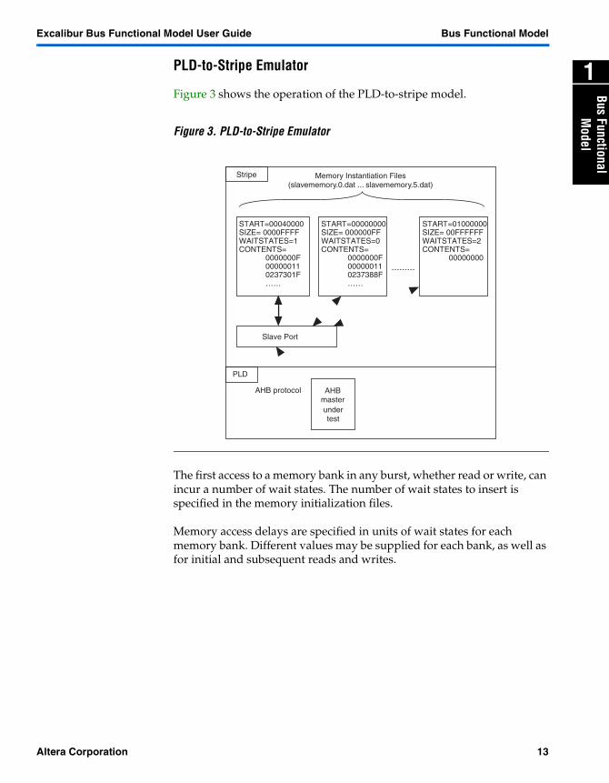
Figure 3 shows the operation of the PLD-to-stripe model.
Figure 3. PLD-to-Stripe Emulator
The first access to a memory bank in any burst, whether read or write, can incur a number of wait states. The number of wait states to insert is specified in the memory initialization files.
Memory access delays are specified in units of wait states for each memory bank. Different values may be supplied for each bank, as well as for initial and subsequent reads and writes.
Slave Port
START=00040000SIZE= 0000FFFFWAITSTATES=1CONTENTS=
0000000F000000110237301F……
AHB protocol
START=00000000SIZE= 000000FFWAITSTATES=0CONTENTS=
0000000F000000110237388F……
START=01000000SIZE= 00FFFFFFWAITSTATES=2CONTENTS=
00000000
Memory Instantiation Files(slavememory.0.dat ... slavememory.5.dat)
Stripe
PLD
AHBmasterundertest
Altera Corporation 13
Bus Functional Model Excalibur Bus Functional Model User Guide
Processing Description
The AMBA Specification documents bus transaction processing; however, the following additional points apply:
� The operation of slavebuserrint (caused by errors on posted writes, general bridge errors, and time-outs) is not simulated.
� The operation of slaveselreg (the bridge-register select) is not supported.
� The PLD-to-stripe emulator accepts all valid transactions. The first transaction (read or write NONSEQ transaction) applied to each bank introduces n wait states, and subsequent transactions incur m wait states, where n and m are specified in the memory configuration file.
� The PLD-to-stripe emulator only samples control and addressing data at the start of a burst operation. No protocol checking is performed.
� The stripe-to-PLD emulator reports, but otherwise ignores, ERROR responses.
Algorithms See the AMBA Specification for further details of bus transactor algorithms.
Output Files The files output from the bus functional model are text log files. When used within a third-party tool, the bus functional model produces one output file. When it is used from within the Quartus II software, details of stripe-to-PLD transactions are recorded separately from PLD-to-stripe activity. See “Filenames” on page 16 for details.
For the stripe-to-PLD interface, the following information is logged:
� Transaction number (i.e., the position in the transactions file)� Transaction address� Transaction type� READ or WRITE� Data� Expected value� Length of the data access (WORD, HALF_WORD, etc.)� Transaction state (OKAY, ERROR,...).
For the PLD-to-stripe interface, the following information is logged:
� Transaction address� Transaction type� Data size� Data written from the PLD
See Appendix E—Output Log File Format for an example output log file.
� There is no special functionality for examining these files from within the Quartus II software.
14 Altera Corporation
Excalibur Bus Functional Model User Guide Bus Functional Model
1
Bus FunctionalM
odel
Using the Model with Third-Party Simulators
You can use the bus functional model to support third-party simulation of the bus interfaces using VHDL and Verilog HDL models.
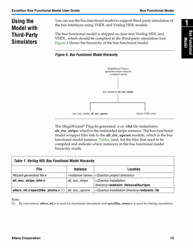
The bus functional model is shipped as clear-text Verilog HDL and VHDL, which should be complied in the third-party simulation tool. Figure 4 shows the hierarchy of the bus functional model.
Figure 4. Bus Functional Model Hierarchy
The MegaWizard® Plug-In-generated .v or .vhd file instantiates alt_exc_stripe, which is the embedded stripe instance. The bus functional model wrapper files link to the alt_exc_upcore module, which is the bus functional model instance. Tables 1and list the files that need to be compiled and indicate where instances in the bus functional model hierarchy reside.
Note:(1) By convention, altera_mf.v is used for functional simulation and apex20ke_atoms.v is used for timing simulation
MegaWizard Plug-In- generated stripe instance:
<instance name>
lpm_instance: alt_exc_stripe
bidir(in VHDL only)bus_func_model: alt_exc_upcore
Table 1. Verilog HDL Bus Functional Model Hierarchy
File Instance Location
Wizard-generated file.v <instance name> <Quartus project directory>
alt_exc_stripe_bfm.v alt_exc_stripe <Quartus installation directory>\eda\sim_lib\excalibur\lpm
altera_mf.v/apex20ke_atoms.v (1) alt_exc_upcore <Quartus installation directory>\eda\sim_lib
Altera Corporation 15

Bus Functional Model Excalibur Bus Functional Model User Guide
Note:(1) By convention, altera_mf.vhd is used for functional simulation and apex20ke_atoms.vhd is used for timing
simulation
Using Model with the Quartus II Software
You use the bus functional model to simulate the bus interfaces from within the Quartus II simulator.
For simulations run natively in the the Quartus II software, the PLD-to-stripe model does not simulate the presence of memory banks. These transactions are recorded in a log file and read transactions always return zeros.
Filenames The filenames expected by the bus functional model depend on whether it is being used as part of a third-party tool or from within the Quartus II software.
For use with third-party tools, bus functional model filenames are as follows:
� mastercommands.dat—Bus control input file for the master port (see Appendix B—Bus Control File for an example of this file)
� slavememory.cfg.dat —Input file containing configuration details for all memory banks (see Appendix C—Memory Configuration File for an example of this file)
� slavememory.n.dat—Input file containing memory bank initialization data, where n is a number between 0 and 5, referring to the appropriate memory bank (see Appendix D—Memory Initialization File for an example of this file)
� output.dat—Output log file containing details of the transactions effected (see Appendix E—Output Log File Format for an example of this file)
Table 2. VHDL Bus Functional Model Hierarchy
File Instance Location
Wizard-generated file.vhd <instance name> <Quartus project directory>
alt_exc_stripe.vhd alt_exc_stripe/bidir <Quartus installation directory>\eda\sim_lib\excalibur\lpm
alt_exc_stripe_arch_bfm.vhd architecture of alt_exc_stripe <Quartus installation directory>\eda\sim_lib\excalibur\lpm
altera_mf.vhd/apex20ke_atoms.vhd alt_exc_upcore <Quartus installation directory>\eda\sim_lib
altera_mf_components.vhd/apex20ke_components.vhd
Component declartion of alt_exc_upcore
<Quartus installation directory>\eda\sim_lib
16 Altera Corporation
Excalibur Bus Functional Model User Guide Bus Functional Model
1
Bus FunctionalM
odel
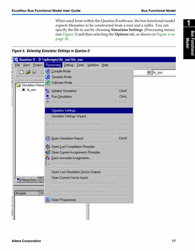
When used from within the Quartus II software, the bus functional model expects filenames to be constructed from a root and a suffix. You can specify the file to use by choosing Simulator Settings (Processing menu) (see Figure 5) and then selecting the Options tab, as shown in Figure 6 on page 18.
Figure 5. Selecting Simulator Settings in Quartus II
Altera Corporation 17
Bus Functional Model Excalibur Bus Functional Model User Guide
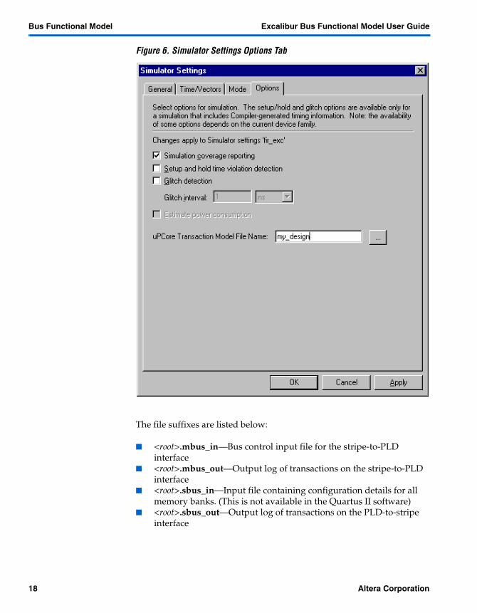
Figure 6. Simulator Settings Options Tab
The file suffixes are listed below:
� <root>.mbus_in—Bus control input file for the stripe-to-PLD interface
� <root>.mbus_out—Output log of transactions on the stripe-to-PLD interface
� <root>.sbus_in—Input file containing configuration details for all memory banks. (This is not available in the Quartus II software)
� <root>.sbus_out—Output log of transactions on the PLD-to-stripe interface
18 Altera Corporation
Excalibur Bus Functional Model User Guide Bus Functional Model
1
Bus FunctionalM
odel
File Locations The bus transaction and memory initialization files must always be present in the simulation directory. An error is generated if no files are found; in addition the bus functional model leaves all stripe-to-PLD interfaces in a null transaction state, and PLD-to-stripe read data is left undefined.
Altera Corporation 19

Notes:

Appendix A
2
Appendix A—Bus CommandLanguage
You can use a high-level, C-type bus command language to specify the commands for the stripe-to-PLD interface; but you then convert the bus commands file to a format suitable for input to the bus functional model. Although it is easier to use bus command language, writing the bus control file in low-level code gives greater flexibility.
Bus Commands Four command types form the bus command transaction set:
� read(<address>, <bit-size>, <length>);� write(<address>, <bit-size>, <length>, <datavalue>[, <datavalue>…]);� idle(<cycles>);� readmatch(<address>,<bit-size>,<length>,<datavalue>[,<datavalue>…]);� read_w(<address>,<bit-size>,<length>);� read_i(<address>,<bit-size>,<length>);� write_w(<address>,<bit-size>,<length>,<datavalue>[,<datavalue>...]);� write_i(<address>,<bit-size>,<length>,<datavalue>[,<datavalue>...]);� readmatch_w(<address>,<bit-size>,<length>,<datavalue>[,<datavalue>...]);� readmatch_i(<address>,<bit-size>,<length>,<datavalue>[,<datavalue>...]);
where address, bit-size, length, and cycles are all decimal integer values.
exc_bus_translate can also handle C-style comments (/*….*/), as shown in the following example:
read(1025, 8, 1); /* read byte at address 1025 */write(1024, 16, 1, 73); /* write the 16-bit value 73 into
address 1024 */idle(20); /* idle for 20 clock cycles (i.e.
using the bus)*/read(1025, 8, 3); /* read bytes at addresses 1025,
1026, 1027 */write(1024, 32, 3, 1, 2, 3); /* write the values 1, 2, 3 into
the words at addresses 1024, 1028, 1032 */
write_i(0x97, 32, 4, 1, 2, 3, 4); /* defined length Incremental burst write of length 4 to hex address 0x97*/
readmatch_w(0xF, 32, 8, 1, 2, 3, 4,5,6,7,8); /*wrap burst read match of length 8 to hex address 0xF*/
Altera Corporation 21
Excalibur Bus Functional Model User Guide Appendix A—Bus Command Language
For a stripe-to-PLD interface file, you must specify a file of bus command transactions. For a PLD-to-stripe interface file, you must specify an initialization file for memory locations, and a control file for details of the behavior of each memory block.
Bus Command Rules
The bus commands are subject to various formatting rules, as listed below:
� Case—Commands are case-sensitive. The command Read is different from read.
� Data sizes—Data can only be used in 8-, 16- and 32-bit formats (byte, half-word, and word).
� Addressing—A byte can occupy any address, a 16-bit value must occupy an address divisible by 2, and a 32-bit value must occupy an address divisible by 4.
� 1-Kbyte boundary limit—Commands must not operate over any 1024-Byte boundary. For example, the following command is illegal:
write(2044, 32, 3, 1, 2, 3);
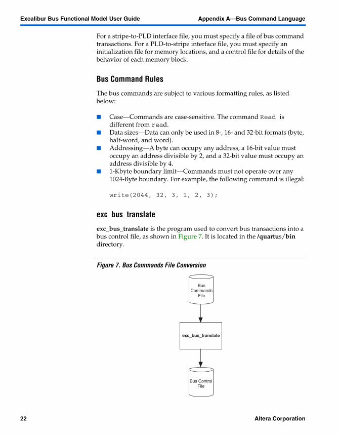
exc_bus_translate
exc_bus_translate is the program used to convert bus transactions into a bus control file, as shown in Figure 7. It is located in the /quartus/bin directory.
Figure 7. Bus Commands File Conversion
Bus ControlFile
exc_bus_translate
BusCommands
File
22 Altera Corporation
Appendix A—Bus Command Language Excalibur Bus Functional Model User GuideAppendix A
2
Running exc_bus_translate
To run exc_bus_translate, type the following command at the command line:
exc_bus_translate <input> <output>
where <input> is the filename of the input bus commands file and <output> is the filename of the hex memory initialization file. If you do not specify an output file, the default output filename is mastercommands.dat.
� Although the output file may be declared as anything you wish, the file must be called mastercommands.dat if you want to use it with third-party simulation tools.
� For the Quartus II internal simulator, the file must be called <prefix>.mbus_in. You can specify which file to use for simulation in the Quartus II Simulator Settings panel.
You can get help on using the script utility by appending -h, e.g.:
exc_bus_translate -h
The production of the output file terminates if an error occurs. Errors are reported in the DOS window.
Altera Corporation 23

Appendix B
3
Appendix B—Bus ControlFile
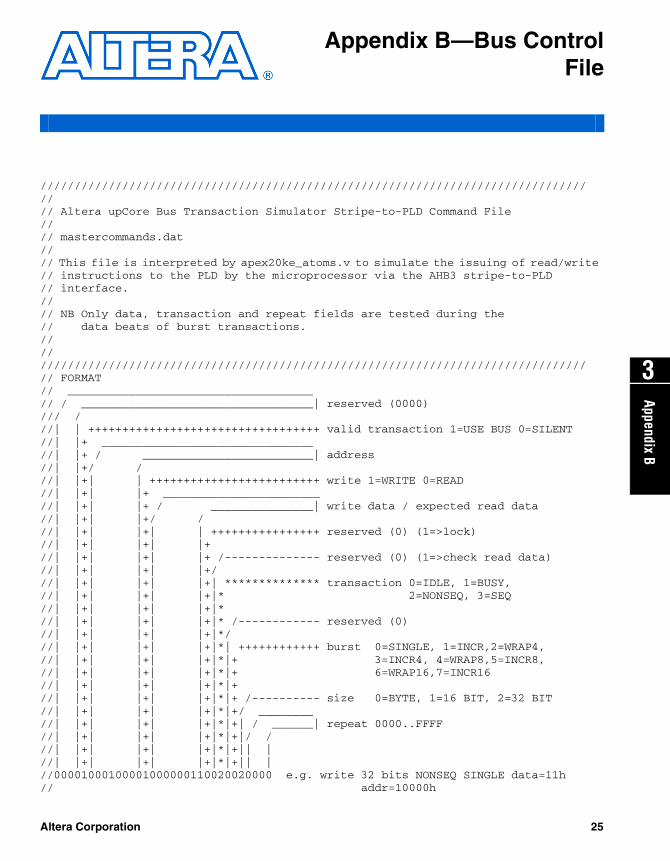
//////////////////////////////////////////////////////////////////////////////////// Altera upCore Bus Transaction Simulator Stripe-to-PLD Command File//// mastercommands.dat//// This file is interpreted by apex20ke_atoms.v to simulate the issuing of read/write // instructions to the PLD by the microprocessor via the AHB3 stripe-to-PLD// interface.//// NB Only data, transaction and repeat fields are tested during the // data beats of burst transactions.////////////////////////////////////////////////////////////////////////////////////// FORMAT// ____________________________________// / __________________________________| reserved (0000)/// ///| | ++++++++++++++++++++++++++++++++++ valid transaction 1=USE BUS 0=SILENT//| |+ _______________________________//| |+ / _________________________| address //| |+/ ///| |+| | +++++++++++++++++++++++++ write 1=WRITE 0=READ//| |+| |+ _______________________ //| |+| |+ / _______________| write data / expected read data//| |+| |+/ ///| |+| |+| | ++++++++++++++++ reserved (0) (1=>lock)//| |+| |+| |+//| |+| |+| |+ /-------------- reserved (0) (1=>check read data)//| |+| |+| |+///| |+| |+| |+| ************** transaction 0=IDLE, 1=BUSY,//| |+| |+| |+|* 2=NONSEQ, 3=SEQ//| |+| |+| |+|*//| |+| |+| |+|* /------------ reserved (0)//| |+| |+| |+|*///| |+| |+| |+|*| ++++++++++++ burst 0=SINGLE, 1=INCR,2=WRAP4,//| |+| |+| |+|*|+ 3=INCR4, 4=WRAP8,5=INCR8,//| |+| |+| |+|*|+ 6=WRAP16,7=INCR16//| |+| |+| |+|*|+//| |+| |+| |+|*|+ /---------- size 0=BYTE, 1=16 BIT, 2=32 BIT//| |+| |+| |+|*|+/ ________//| |+| |+| |+|*|+| / ______| repeat 0000..FFFF//| |+| |+| |+|*|+|/ ///| |+| |+| |+|*|+|| | //| |+| |+| |+|*|+|| | //00001000100001000000110020020000 e.g. write 32 bits NONSEQ SINGLE data=11h// addr=10000h
Altera Corporation 25
Appendix B—Bus Control File Excalibur Bus Functional Model User Guide
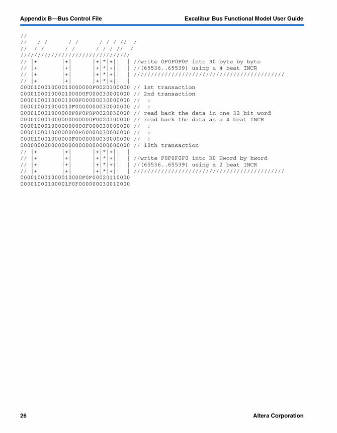
//// / / / / / / / // /// / / / / / / / // /////////////////////////////////// |+| |+| |+|*|+|| | //write 0F0F0F0F into R0 byte by byte// |+| |+| |+|*|+|| | //(65536..65539) using a 4 beat INCR // |+| |+| |+|*|+|| | ////////////////////////////////////////////// |+| |+| |+|*|+|| | 000010001000010000000F0020100000 // 1st transaction0000100010000100000F000030000000 // 2nd transaction 00001000100001000F00000030000000 // :000010001000010F0000000030000000 // :000010001000000F0F0F0F0020030000 // read back the data in one 32 bit word000010001000000000000F0020100000 // read back the data as a 4 beat INCR0000100010000000000F000030000000 // :00001000100000000F00000030000000 // :000010001000000F0000000030000000 // :00000000000000000000000000000000 // 10th transaction// |+| |+| |+|*|+|| | // |+| |+| |+|*|+|| | //write F0F0F0F0 into R0 Hword by hword// |+| |+| |+|*|+|| | //(65536..65539) using a 2 beat INCR // |+| |+| |+|*|+|| | ////////////////////////////////////////////000010001000010000F0F0002011000000001000100001F0F000000030010000
26 Altera Corporation

Appendix C
4
Appendix C—MemoryConfiguration File
//////////////////////////////////////////////////////////////// Altera upCore Bus Transaction Simulator Slave Memory Configuration File//// slavememory.cfg.dat//// This file is interpreted by apex20ke_atoms / altera_mf to initialize // the memory space available through the PLD-to-stripe slave port.//// The address space is divided into 6 banks each of up to 65536 32-bit words.// Banks should not overlap.// Memory is little-endian.// Bank start addresses should be word aligned.//// The initial contents of each bank are defined in Verilog compatible hex files// slavememory.<bank number>.dat//// NB unused banks should be specified as all zeros////////////////////////////////////////////////////////////// FORMAT// // ******** - Bank Start byte address// ******** - Bank End byte address // ** - Number of wait states to insert before first access to bank// ** - Number of wait states on subsequent cycles of burst access// HHHHHHHHHHHHHHHHHHHH// | || |++**// | || |++**// 00000000000000FF0000 // Bank zero contains 255 bytes between 00 and FF// | || |++** // initialization file: slavememory.0.dat// | || |++** // no wait states/// // /++**// // /++**// || |++**//-----||------|++** ///////////////////////////////////////// || |++**// || |++**00000000000000FF0000 // Bank zero contains 255 bytes between 00 and FF00000000000000000000 // Bank 100000000000000000000000000000000000000000000000000000000000000000000000000000000 // Bank 5//////////////////////////////////////////////////////////////
Altera Corporation 27


Appendix D
5
Appendix D—MemoryInitialization File
//////////////////////////////////////////////////////////////////////////////////
//
// Altera upCore Bus Transaction Simulator Slave Memory Initialization File
//
// slavememory.0.dat
//
// This file is interpreted by apex20ke_atoms.v to initialize the memory space
// available
// through the PLD slave port.
//
// The data in this file should correspond to the memory image to be loaded into the
// bank.
// The image should be
//
//////////////////////////////////////////////////////////////////////////////////
//
// ******** - Initial value
// HHHHHHHH
//
//////////////////////////////////////////////////////////////////////////////////
//
00000001// addr=@00
00000002// addr=@04
00000003
00000004
00000005
00000006
00000007
00000064
00000065
//////////////////////////////////////////////////////////////////////////////////
Altera Corporation 29


Altera Corporation 31
Appendix E
6
Appendix E—Output LogFile Format
SLAVE: addr=[00010000] WRITE data=[0000000f] BYTESLAVE: addr=[00010001] WRITE data=[00000f00] BYTEMASTER: trans=[ 1] addr=[00010000] WRITE data=[0000000f] expected=[0000000f]
BYTE OKAYSLAVE: addr=[00010002] WRITE data=[000f0000] BYTEMASTER: trans=[ 2] addr=[00010001] WRITE data=[00000f00] expected=[00000f00]
BYTE OKAYSLAVE: addr=[00010003] WRITE data=[0f000000] BYTEMASTER: trans=[ 3] addr=[00010002] WRITE data=[000f0000] expected=[000f0000]
BYTE OKAYMASTER: trans=[ 4] addr=[00010003] WRITE data=[0f000000] expected=[0f000000]
BYTE OKAYSLAVE: addr=[00010000] READ data=[0f0f0f0f] WORDMASTER: trans=[ 5] addr=[00010000] READ data=[0f0f0f0f] expected=[0f0f0f0f]
WORD OKAYSLAVE: addr=[00010000] READ data=[0000000f] BYTESLAVE: addr=[00010001] READ data=[00000f00] BYTEMASTER: trans=[ 6] addr=[00010000] READ data=[0000000f] expected=[0000000f]
BYTE OKAYMASTER: trans=[ 7] addr=[00010001] READ data=[00000f00] expected=[00000f00]
BYTE OKAYSLAVE: addr=[00010002] READ data=[000f0000] BYTESLAVE: addr=[00010003] READ data=[0f000000] BYTEMASTER: trans=[ 9] addr=[00010002] READ data=[000f0000] expected=[000f0000]
BYTE OKAYMASTER: trans=[ 10] addr=[00010003] READ data=[0f000000] expected=[0f000000]
BYTE OKAYSLAVE: addr=[00010000] WRITE data=[0000f0f0] HALF
WORDSLAVE: addr=[00010002] WRITE data=[f0f00000] HALF
WORDMASTER: trans=[ 12] addr=[00010000] WRITE data=[0000f0f0] expected=[0000f0f0]
HALF WORD OKAYMASTER: trans=[ 13] addr=[00010002] WRITE data=[f0f00000] expected=[f0f00000]
HALF WORD OKAY