
Examples of fractures, failures and rejections in engineering
61
- 1 - Examples of fractures, failures and rejections in engineering materials and components C.Dasarathy May 2011
Transcript of Examples of fractures, failures and rejections in engineering

- 1 -
Examples of fractures, failures and rejections in engineering
materials and components
C.Dasarathy
May 2011

- 2 -
Preface
For over two decades, I have had the good fortune of lecturing to graduate, post-graduate
and doctoral students of engineering at different universities within the UK and abroad.
Engineering students of various disciplines, civil, mechanical, electrical, metallurgical,
materials, aeronautical, etc deal with materials to varying levels of depth, penetration and
expertise. Some even learn the basics of predictive failure analysis. Yet, they are not
exposed to a broad spectrum of examples of failures, fractures and rejection of materials
as well as components.
A civil engineer successfully designed a motorway bridge. Yet, within months after the
opening of a new section of a motorway bridge in Melbourne in 1962, there was a
collapse of this section in 1963; fortunately, no lives were lost. The reason for the failure
was apparently related to the fusion welds that were employed to join the different steel
sections. The civil engineer had little awareness of the complex metallurgical issues
involved.
It is precisely for these reasons that an attempt is being made in this compilation to
provide engineering students as well as those actively engaged in peripheral disciplines in
the industry an awareness of the multitude of the issues involved when one studies
failures and fractures in engineering components. This compilation covers a broad range
of examples where, failures, fractures and rejections have occurred in the engineering and
manufacturing sectors. It is hoped that this will prove to be a source of reference and will
help to broaden the awareness of the readers and, indeed, enthuse them to probe deeper.
An introduction to this compilation
There are several reasons for failure:-
1. Rejection can be on the grounds of appearance.
2. Rejection can also result from poor surface quality
3. The properties not being uniform/consistent in a batch can lead to rejection
4. There can be premature failure in service
5. There can be failure of critical components that can endanger human lives
6. Failure of components can lead to the threat of litigation
7. Failures, fractures and rejections can lead to a big fall in profitability arising from a
loss of business or delivery schedules not being met
Design engineers specify a list of material properties based on the requirements of the
component. These properties are developed as a result of the presence of an appropriate
microstructure in the material. Parameters such as the grain size, grain shape, precipitate
type, size, volume fraction and distribution characterise the microstructure. Two essential
factors govern the development of the microstructure-
1 the composition of the material

- 3 -
2.the processing parameters such as, temperature, time at temperature, strain, strain rate,
heating as well as cooling rates, etc.
Given that the above two factors are controlled to precise limits and that they are
reproducible, the material will develop a microstructure that is appropriate to the
properties required.
In practice, however, problems arise due to several reasons; these include
1 properties are not up to specification
2 processing has been incorrect
3 unexpected loss of some key elements in the composition; such loss can occur due to
segregation, oxidation or decarburisation during processing
4. incorrect design of components ( as in faulty design of castings)
5. the use of incorrect temperatures ( as in hot rolling), incorrect pressures ( as in press
shops that produce automotive panels, etc)
6. a general unawareness of the issues involved as well as a breakdown in
communications
It is a combination of such factors that leads to failures, fractures and rejections of
engineering components. The following compilation covers a broad range of these
examples that have been observed in automotive, aerospace and engineering
components produced from metallic as well as composite materials. The failed
components used here as examples have been produced by a range of manufacturing
processes that include rolling, deep drawing, hydroforming, welding, superplastic
forming, protective zinc coating, etc.
C.Dasarathy

- 4 -
Table of contents
Section Content Page No.
1 Preface and an introduction to this compilation 2
2 Table of contents 4
3 Examples of fractures, failures and rejections 6
3.1 The stress-strain diagram 6
3.2 Discontinuous yielding 8
3.3 Plastic deformation during forming of sheet steel components 11
3.4 Deep drawing 12
3.5 Stretch forming 15
3.6 Anisotropy and earing behaviour 17
3.7 Wrinkling during forming 18
3.8 Rejection of formed components due to other reasons 19
3.9 True stress-True strain curve 20
3.10 Ductile fractures and the effect of non-metallic
inclusions on ductility 20
3.11 When and why do materials fail in a brittle manner? 23
3.12 Fatigue failures 25
3.13 Failures in welded structures 27
3.14 Failures in castings 31
3.15 Hydroforming and failures that can occur 36
3.16 Superplastic forming ,examples of failures 38
3.17 Aircraft engine component failures due to a combination of
- 5 -
high temperatures and stress levels 43
3.18 Stress corrosion cracking 46
3.19 Corrosion in the absence of stress ; failures in zinc coated
sheet steel components 48
3.20 Surface defects on sheet steels which lead to rejection 52
3.21 Incorrect processing temperatures can lead to
rejection of materials 56
3.22 Examples of failures in composite materials 59
4. Remarks in conclusion 61
5. Acknowledgements 61
- 6 -
3.1 The stress-strain diagram
From my experience of marking examination papers, students often fail to write the
units of the X and Y axes , N/mm2 or Tons/inch
2. They need to be reminded of the
importance of this.
The elastic modulus , E, influences the stiffness/rigidity in bending. This follows the
equation Stiffness S= E.I where I is the moment of inertia. Students need to know
why the E for steels is ~210GPa whilst that of aluminium is ~70GPa. For that matter,
why is the E for diamond as high as 1050-1200 GPa ?
The strain rate/ crosshead speed is small as one approaches the yield point; once, this
has been recorded, the strain rate is increased so as to complete the test to fracture in a
relatively short time.
Implicit in the construction of the Engineering stress-Engineering strain diagram is
the assumption that the cross-sectional area of the test piece remains constant. In
reality, this is seldom the case since the area continually decreases with increasing
strain. This is, hence, the reason why the True stress-True strain diagram is often
more representative.
Students need to appreciate that the strain beyond the yield point is plastic strain.
Also, that the mode of straining here is uniaxial tension. Commercial press forming
of sheet materials is often carried out at much higher strain rates; the stress systems
are also much more complex than simple uniaxial tension. Hence, the question often
arises as to how relevant are the data from such tests in being able to predict the
material behaviour of automotive components produced under high speed ( high
strain rates) and complex stress systems.
Material properties are affected by the strain rate. A case in point is the behaviour of
sheet steels in cars subjected to crash velocities/ strain rates . The strength levels
increase with the strain rate. Hence, the information derived from Fig1 bears no
relevance to the conditions that prevail at high strain rates. The students need to be
aware of this. In fact, the test procedure to determine the properties at high strain rates
is more complex.
Ductility is reflected in the value of the Total Elongation. Softer materials are more
ductile. Students may also be invited to consider why face centered cubic metals such
as Ni, Cu, Au, Ag, Al and gamma Fe are more ductile than body centered cubic
metals such as Cr, Mo, and alpha Fe.

- 7 -
Fig.1 Stress–strain curve showing typical yield behavior for nonferrous alloys. Stress
(σ) N/mm2 is shown as a function of strain (ε)
1: True elastic limit
2: Proportionality limit
3: Elastic limit
4. 0.2% off set yield strength, known as proof stress
(data obtained from Internet.Wikipedia)

- 8 -
Fig 2
stress
strain
A
B C
A= upper yield point
B=lower yield point
B to C= yield point
elongation
Luders
Lines at
45 0
to
the
tensile
axis
appear
over
the
strain
range B
to C
σ
σ
3.2 Discontinuous yielding and its effects
Stress-strain curve for steels
(Stress in N/mm2)
Fig 2a
C

- 9 -
Fig 2 shows discontinuous yielding ie. a sharp upper yield point, A, a lower yield
point B and an yield point elongation (YPE)/BC in steels.
YPE triggers the appearance of Luders bands at 450 to the stress axis. (Figs2,2a &
3). Why does this happen at 450? This is because the max. critical resolved shear
stress is at 450
to the principal stress axis
The students need to be aware of why this phenomenon occurs; that interstitial
atoms , C and N are responsible for the pinning of dislocations, thus depleting the
availability of mobile dislocations
Fig 3
In commercial pressings where the stress system is not merely uniaxial tension but, in
fact , more complex, Luders lines are replaced by Stretcher Strain marks (Figs 4&5) .
When sheet steels are used in the manufacture of external autobody components , door ,

- 10 -
roof, bonnet panels, etc, these Stretcher Stain marks are highly undesirable. In fact, they
often lead to the rejection of otherwise sound materials on the grounds of the surface
quality being unacceptable.
Fig 4
Fig 5
How is ‘discontinous yielding’ replaced by ‘continuous yielding’ in order to avoid the
formation of ‘Stretcher Strain marks on exterior autobody panels ?
Skin passing/Temper rolling, a very small amount ( ~0.8%) cold rolling of
annealed sheet steels is the practice normally employed .
By adding Ti or Nb to the steel; these tie the C and N up as TiCN or NbCN ; the
steel thus becomes free of interstitials, C or N.

- 11 -
The students could consider why this happens; the slight amount of cold rolling ,
most of which is confined to the skin provides just enough mobile dislocations to
facilitate the progress of plastic deformation .In the absence of a well defined yield point,
the parameter 0.2% proof stress is used instead ( see Fig1)
3.3 Plastic deformation during forming of sheet steel components
We now proceed along the strain axis in Figs 1&2 and apply plastic deformation to
produce the example shown in Fig 6
Fig6
This is a car door panel (outer), made from sheet steel, typically about 0.9-1.2 mm thick.
The points to note are
Levels of strain in the panel vary significantly; the students can guess as to the extent of
strain gradient within the panel
Some regions are more strained than others
How is this strain applied ?
Essentially, in commercial practice, there are two major modes of forming:
deep drawing and stretch forming
- 12 -
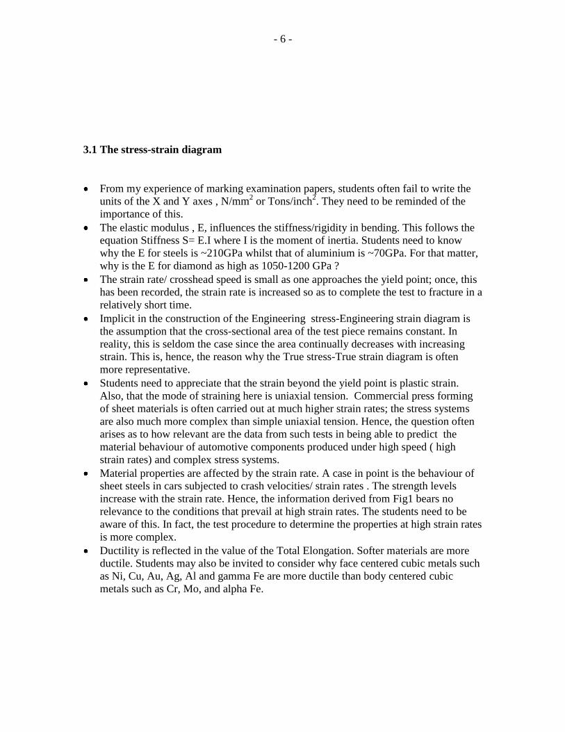
3.4 Deep drawing
Fig7 The key parameters in deep drawing are
The force on the punch,
The rate of punch travel,
The blank holder pressure

- 13 -
Fig 8
Fig 8 is a sheet steel ( thickness ~ 0.9mm) pressing / an oil sump in a car
The major mode of plastic straining is via a deep draw
Deep drawability is assessed by the plastic strain ratio ie, the ratio of the
width strain to the thickness strain in a tensile test piece/ Lankford
parameter , R or r
The corners exhibit ‘’ears’’, this is because of anisotropy
Anisotropy implies that the properties are different in the three directions
ie. along ,across and at 450
to the direction in which the sheet was
originally rolled in the mill
The mean plastic anisotropy, Rm or rm is ( R0 + 2R45 + R 90 ) ÷ 4
Rolled sheet materials exhibit planar anisotropy
Following the draw, all the ‘’ears’’ are trimmed away from the main
pressing

- 14 -
Fig 9
This is from a sheet steel about 1.4-1.6mm thick
This is an example of a failed draw
The mean plastic strain ratio, Rm, calculated from the 00,
900
and at 450
to the rolling direction was relatively low
Significant thinning is evident as the wall thickness strain rose to a high
level. Also evident are the score marks on the wall; this may suggest that
the tooling was not set correctly or that the level of lubrication was poor .

- 15 -
3.5 Stretch forming
Fig 10
Stretching (Fig 10) is the second major mode of forming components
from sheet
Deformation around the radii of a bath or a kitchen sink is based on
stretching/ for eg. the failure around the radii in the bath ( Fig 11)
The parameter, work hardening index, n, derived from the slope of the
log.true stress
log/true strain
relationship,
reflects the
stretchability
Components can
fail when the ‘n’
value is low
Fig 11

- 16 -
Fig 12
Fig 13
Fig 12 shows a successful pressing based on a steel with good
stretchability ie. a high ‘n’ value
Fig 13 shows the failure around the radii of the component in a steel with
a poor ‘ n’ value
Other than this difference in the ‘n’values, both materials showed
comparable deep drawaibity ie. their R m values were similar
Also to be noticed in both figures is the pronounced earing arising from
anisotropy
Clear evidence of wrinkling can be seen on the ears; this arises from
inadequate blank holder pressure exerted during forming

- 17 -
3.6 Anisotropy and earing
behaviour
Fig 14a
Fig 14b
Fig 14a is the first stage pressing. Note the onset of
earing. Fig 14b is the final pressing. Fig 14c shows the
tearing that has led to the failure . A combination of
poor deep drawabilty and stretchabilty has led to the
failure.
Also evident are
a. pronounced earing due to anisotropy of the steel
sheet
( seen in Fig 14b)
b. clear evidence of wrinkling ; evidently, the correct
blank holder pressure may not have been used.
Fig 14c

- 18 -
3.7 Wrinkling during forming
Fig 15 shows the importance of the optimum blank holder pressure to be applied.( see
also Figs 7 &10)
Fig 15

- 19 -
3.8 Rejection of formed components due to other reasons
Internal defects such as non-metallic inclusions ( to be described in detail later) can result
in failures in otherwise sound pressings. An example is seen in Fig 16.
Fig16
The settings in the press can have very significant effects on the operation. Material that
is entirely satisfactory can be rendered useless by incorrect press parameters, such as the
rate of punch travel, force applied on the punch, blank holder pressure, die clearance ,
level of lubrication, etc. (Fig17).
Fig17

- 20 -
3.9 True stress-True strain curve
Fig.18 shows the difference between the Eng. stress/Engineering strain curve and the
True stress/True strain curve. With the former, it is assumed that the cross sectional area
remains unchanged whilst with the latter, the cross sectional area changes steadily with
increasing strain.
Fig 18
As the level of strain increases, we approach the point of plastic instability; in ductile
samples, a typical necking failure is the outcome ( Figs 19 &20). Inin
3.10 Ductile fractures and effect of non-metallic inclusions on ductility
Fig 19 Ductile fracture in a rod sample Fig 20 Ductile fracture in a sheet sample

- 21 -
Ductile materials exhibit significant total elongation prior to fracture. Typically, with a
well annealed sheet steel ( mild steel), the total elongation over a 50mm gauge length can
exceed about 40%.Fig 21 shows a scanning electron micrograph of a typical ductile
fracture; the fibrous nature of the fracture is clearly evident.
In industrial applications , there are many occasions when a seemingly ductile material
fails prematurely. This is because of the presence within the material of non-metallic
inclusions (NMIs); these are metallic oxides, sulphides and silicates that get entrapped
during solidification. Particles of entrapped slag or eroded refractories used in the
tundish whilst teeming get worked within the material during forging or extrusion or hot
rolling, cold rolling etc. These NMIs are sub-microscopic particles that often escape
detection by conventional tests. However, when the material is used to produce
components, these particles act as stress raisers and lead to the fracture or splitting during
forming. The particles create voids around them, adjacent voids coalesce thereby creating
large discontinuities within the material. These are shown in Figs 22-25.
Fig 21 Ductile fracture Fig 22 Ductile fracture showing Fig 23 Ductile fracture
a NMI & a void around it & an enlarged void
with a NMI within
Fig 24 Effect of
NMIs (from
Roehrig,
CCtechnologies,
Dublin/ obtained
from the Internet)

- 22 -
Due to poor production practices, commercial materials can, at times, suffer from a
higher than normal level of contamination from NMIs. Fig 25 is an example.
Components produced from such a material will fail either during the production stage or
after a very short time in service.
Fig25
Fig26
Fig 26 clearly shows that production practices need to be very carefully controlled
in order to drastically reduce the NMI count. This is particularly important in the
case of critical aircraft components such as turbine discs and blades. The level of
inspection must be such that freedom from NMIs down to an agreed size is
ensured in the material supplied to the customer.

- 23 -
3.11 When and why do materials fail in a brittle manner ?
Fig 27 Fig 28
It is clear from Figs 27 and 28 that the ductility ( as measured by the ‘total elongation to
fracture’) and the stretchabilty ( as measured by ‘n’, the work hardening index / see also
Fig 10) decrease as the tensile strength increases.
Martensitic steels are typical examples. Heavy cold working , for example, by cold
rolling, wire drawing or extruding, also leaves the materials with very low ductility. In
these instances the materials fail in a brittle manner.
Materials that are otherwise ductile at ambient temperatures and above can fail in a brittle
manner when exposed to sub-zero temperatures. This is known as the
‘ductile to brittle transition’ behaviour, typical of Body Centered Cubic (BCC) materials
such as Fe ( steels), Cr and Mo. Plate or structural steels that are used in oil rig
installations, platform decks, jacket legs secured to the sea bed are examples where the
steels are alloyed with nickel to ensure that the components do not fail on impact in a
brittle manner when exposed to temperatures of around -40 to -800C.

- 24 -
Figs 29- 31 are examples of heat treated steel components that failed in a brittle
manner.
Fig 29 Fig 30 Fig 31
Fig 31 is a part of the drive shaft (shown in the right of the figure), a
broken fragment of which impacted the wall of the magnesium casting oil sump
( shown in the left of the figure) within which the drive shaft is located. The
impacting broken fragment tore a hole through the casting( shown with an arrow)
and led to a total loss of the oil within the sump.
Fig 32 is an example of a typical brittle fracture , also known as a clevage
fracture.
Fig 32

- 25 -
3.12 Fatigue failures
Fatigue fractures similar to those in Figs 33 ( a bolt) & 34 ( a pulley) show features,
often described in books as clam shell markings or beach markings.
Fig 33 Fig 34
In the electron microscope, these striations appear as in
Fig 35. Fig 36 explains the manner in which these
striations appear on the fracture surfaces.
Fig 35
Fig 36

- 26 -
Fig 37 shows an example of a valve spring ( info. supplied from Ford/Dunton) that had
failed in fatigue prematurely. Examination of the fracture surface showed that the cracks
that led to the failure of the spring had nucleated from a NMI that was embedded within
the steel. This is seen if Figs 38&39. The role of the NMIs is also seen in Figs.21-26.
Fig
38
Fig 37
Fig 39
Other issues in this context are examples of abrasion of components subjected to fatigue
loading . Fig.40 shows the pitting/ abrasion and wear on the roller bearings and the cage.
Fig 40
- 27 -
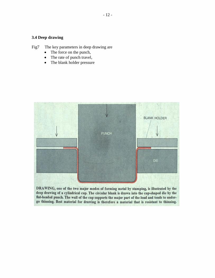
3.13 Failures in welded structures
Fig 41 Fig 42
Fig 43
Fig 44

- 28 -
Examples of the ‘Heat Affected Zone ’ HAZ, are seen in Figs 41-44. Potentially, this area
is most prone to failure for a number of reasons.
1. The weld metal solidifies , there is a change from the liquid to solid state with
accompanying volume changes.
2. The weld metal may often exhibit porosity as well as large dendritic crystals,
similar , in principle , to as- cast structures.
3. Rapid cooling as the heat source is removed can lead to the formation of
martensite that is hard and brittle
4. Rapid solidification can also lead to residual stresses in the HAZ.
Fig 45 Fig 46
Fig 47

- 29 -
Fig45 shows the fusion welds in an automotive component made from an austenitic
stainless steel. On cooling from the weld heat as the electrode is removed, certain areas
in the immediate vicinity of the weld transform to martensite. Potentially, this leads to
brittleness in the HAZ. Figs 46 & 47 clearly show the failure in the HAZ. It is interesting
to note in Fig 47 that the weld area exhibits a ‘ herring bone’ appearance, typical of as –
cast structures.
Damp electrodes can often be responsible for the entrapment of hydrogen which leads to
the weld cracking in the vicinity of the HAZ. An example is shown in Fig 48.
Fig 48
The role of the NMIs has already been shown in several examples of failures in Figs 22-
26 and Figs 37-39 . NMIs that remain relatively soft at hot rolling temperatures such as
~1200 0 C get deformed and are strung out along the rolling direction; they remain
undetected within the hot rolled product. When components produced from such
materials are welded and put into service, they fail in a manner similar to that seen in Fig
49.
Fig 49
- 30 -
The strong directionality of the almost parallel cracks indicates that the cracking has
taken the line of least resistance ie. along the directionally strung out NMIs within the
material.
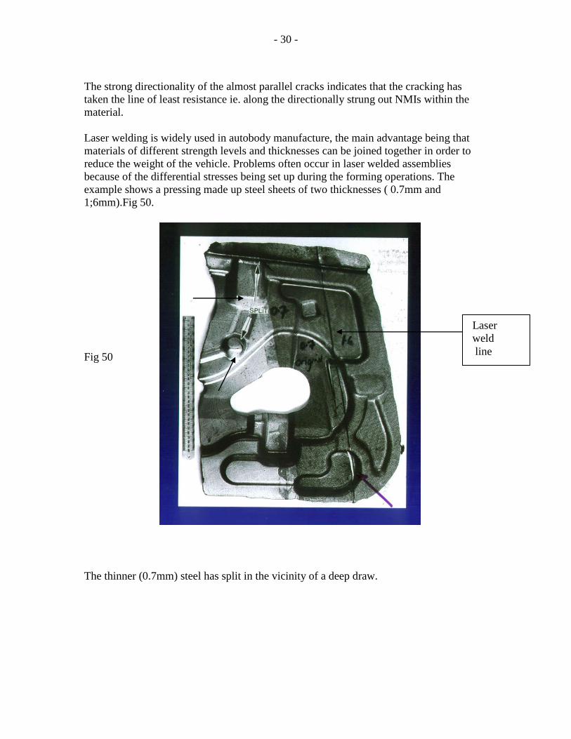
Laser welding is widely used in autobody manufacture, the main advantage being that
materials of different strength levels and thicknesses can be joined together in order to
reduce the weight of the vehicle. Problems often occur in laser welded assemblies
because of the differential stresses being set up during the forming operations. The
example shows a pressing made up steel sheets of two thicknesses ( 0.7mm and
1;6mm).Fig 50.
Fig 50
The thinner (0.7mm) steel has split in the vicinity of a deep draw.
Laser
weld
line

- 31 -
3.14 Failures in castings
Fig 51 Fig 52 Fig 53
Figs 51-53 are examples of massive steel castings ( about 75 -100 Tonnes in weight)
produced by the River Don works , Sheffield .These are used as nodes to secure the
jacket legs that are fixed in the sea bed. These stabilise the platform decks in the off-
shore oil industries. ( photos/ courtesy of Dr. Roger Richardson)
An important point to appreciate whilst dealing with castings relates to the dendrites that
form as the casting solidifies. After the
formation of the chill /equiaxed crystals
immediately adjacent to the mould
surface, large dendritic crystals ( shown
by an arrow in Fig 54) form and grow in
the direction of the temperature gradient.
The bigger the casting, the slower the
cooling rate and larger is the size of the
dendrites.
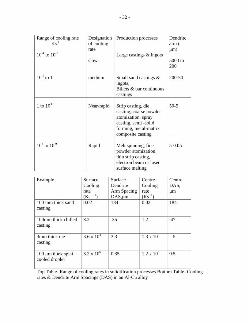
The Tables below show how the size and
the manner of castings affect the cooling
rates and, hence, the size of the dendrites.
Fig 54
- 32 -
Range of cooling rate
Ks-1
10-4
to 10-2
Designation
of cooling
rate
slow
Production processes
Large castings & ingots
Dendrite
arm (
μm)
5000 to
200
10-2
to 1
medium
Small sand castings &
ingots,
Billets & bar continuous
castings
200-50
1 to 103
Near-rapid
Strip casting, die
casting, coarse powder
atomization, spray
casting, semi -solid
forming, metal-matrix
composite casting
50-5
103 to 10
9
Rapid
Melt spinning, fine
powder atomization,
thin strip casting,
electron beam or laser
surface melting
5-0.05
Example Surface
Cooling
rate
(Ks - 1
)
Surface
Dendrite
Arm Spacing
DAS,μm
Centre
Cooling
rate
(Ks -1
)
Centre
DAS,
μm
100 mm thick sand
casting
0.02 184 0.02 184
100mm thick chilled
casting
3.2 35 1.2 47
3mm thick die
casting
3.6 x 10³
3.3 1.3 x 10³ 5
100 μm thick splat –
cooled droplet
3.2 x 10⁶ 0.35 1.2 x 10
6 0.5
Top Table- Range of cooling rates in solidification processes Bottom Table- Cooling
rates & Dendrite Arm Spacings (DAS) in an Al-Cu alloy
- 33 -
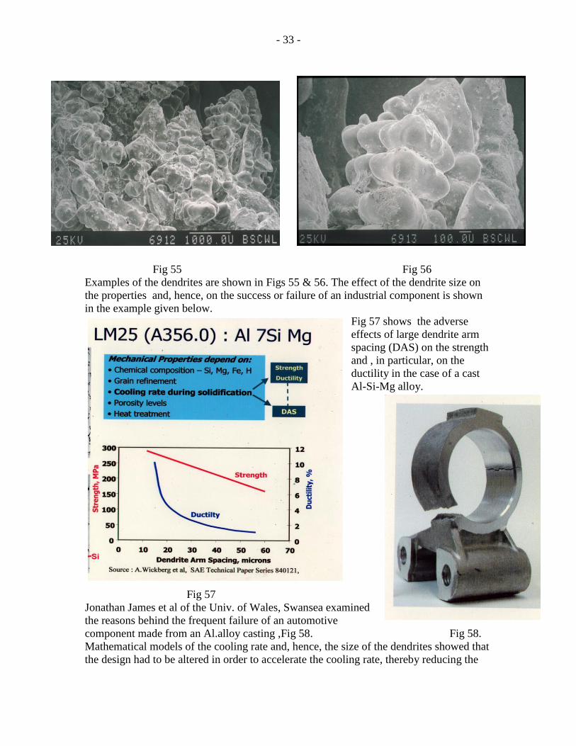
Fig 55 Fig 56
Examples of the dendrites are shown in Figs 55 & 56. The effect of the dendrite size on
the properties and, hence, on the success or failure of an industrial component is shown
in the example given below.
Fig 57 shows the adverse
effects of large dendrite arm
spacing (DAS) on the strength
and , in particular, on the
ductility in the case of a cast
Al-Si-Mg alloy.
Fig 57
Jonathan James et al of the Univ. of Wales, Swansea examined
the reasons behind the frequent failure of an automotive
component made from an Al.alloy casting ,Fig 58. Fig 58.
Mathematical models of the cooling rate and, hence, the size of the dendrites showed that
the design had to be altered in order to accelerate the cooling rate, thereby reducing the

- 34 -
size of the dendrite and , thus making the casting less prone to failure. Their results are
shown in Figs. 59-60.
Fig59
Fig60
The modified design is shown in the right of Figs 59 & 60. Apparently, the new design
proved more satisfactory to the customer and the incidence of failure was drastically
- 35 -
reduced. The example shows how important it is to control the cooling rate so as to limit
the size of the dendrite and thus reduce the risk of a failure of the casting.
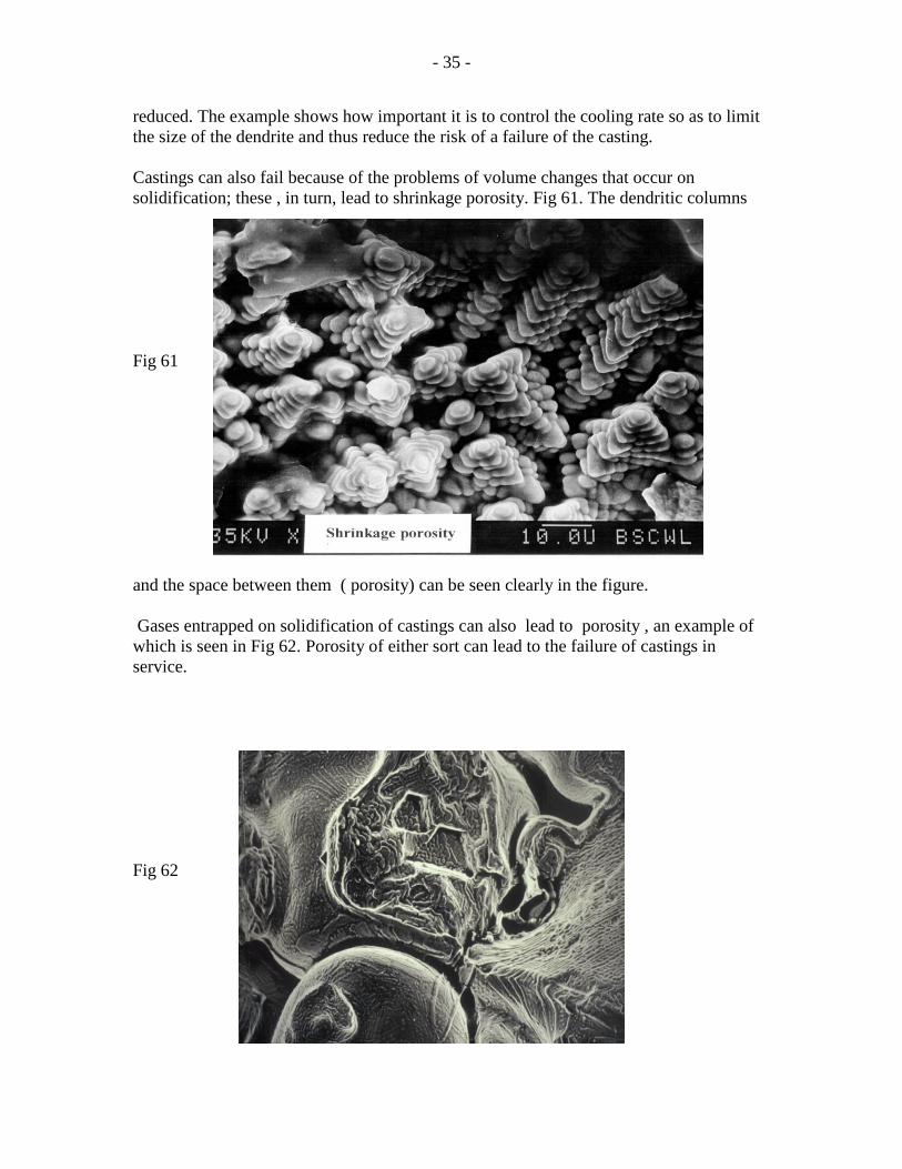
Castings can also fail because of the problems of volume changes that occur on
solidification; these , in turn, lead to shrinkage porosity. Fig 61. The dendritic columns
Fig 61
and the space between them ( porosity) can be seen clearly in the figure.
Gases entrapped on solidification of castings can also lead to porosity , an example of
which is seen in Fig 62. Porosity of either sort can lead to the failure of castings in
service.
Fig 62

- 36 -
3.15 Hydroforming
Conventional forming methods based on deep drawing and stretch forming have already
been discussed with reference to Figs. 6-17. Over the past decade or so, hydroforming
has been employed with great success. With tubular automotive components such as side
roof rails, exhaust manifolds and exhaust systems, engine cradles, etc, the benefits are
significant in that the operation can be completed in one step. This is in contrast to
conventional forming, where several components are formed individually and joined
together by spot welding. The operations involved in hydroforming are shown in Figs 63
& 64.
Fig 63 Fig 64
The pre-bending of the tube follows the design imported from the CAD file relating to
the component. When the ends are sealed and the tube filled with the fluid and axial force
is applied, the pressures reach in excess of 600 bar. Hydraulic pressure is used to expand
the tube to follow the contours of the die cavity.
Trial and error help to optimise the pressure and the axial force applied during forming.
Fig 65 illustrates how critical it is to avoid failures such as those shown in Figs 66 & 67.
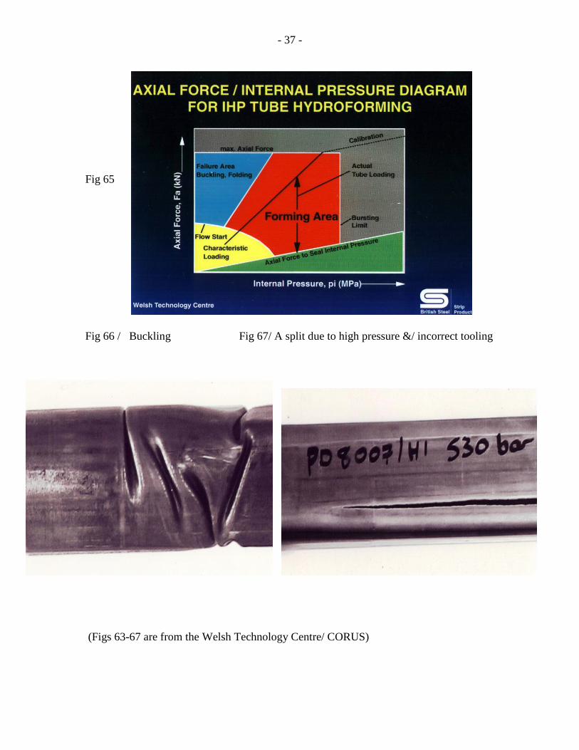
- 37 -
Fig 65
Fig 66 / Buckling Fig 67/ A split due to high pressure &/ incorrect tooling
(Figs 63-67 are from the Welsh Technology Centre/ CORUS)
- 38 -
3.16 Superplastic forming (SPF)
The total elongation values of ductile materials such as mild steels , typically, are about
40% as measured over a test piece of 50mm gauge length. ( see Figs 2,19 & 20). These
exhibit the typical ‘necking’ failures. In contrast to these figures, as far back as about
1934, Pearson discovered the phenomenon of superplasticity; given the correct test
temperatures and strain rates, he was able to obtain total elongation values of 1950 % ! It
is this feature that has ,over the past two decades, been commercially exploited with
certain aluminium, titanium and nickel alloys.
Conventional forming systems discussed with reference to Figs.6-17 and Figs.63-67,
have high tooling costs, involve high strain rates, leave the components with problems
such as ‘ spring back’ and are used for high volume, mass produced parts. In contrast,
SPF entails minimal tooling costs and slow strain rates; it is , hence, not ideal for high
volume, mass produced parts and leaves the components in a relatively strain-free
condition. However, SPF involves operating at relatively high temperatures ie. when the
materials behave superplastically. The aerospace industry has benefitted significantly
from the SPF methods.
Essentially, the strip is heated to a high temperature, relatively close to the melting point ;
it is about 510 0 C with aluminium alloys and > 900
0 C with titanium alloys. The heated
strip is placed in the die chamber where gas ( inert) pressure is used to force the sheet to
follow the contours of the die ( female forming) or to drape over the tool ( drape forming)
or male forming..The strain rate involved is slow. Often, more than one sheet is used,
sometimes with separators or spacers in between. After SPF, the components still remain
at the SPF temperature and the gas pressure is raised to bring about homogenisation of
the microstructure. This is called diffusion bonding and can last a few hours. Examples of
SPF procedures are given in Figs. 68 & 69.
In comparison to the automotive industry, the aerospace industry entails a relatively low
volume production. SPF has proved highly beneficial to the production of aerospace
components. SPF is widely employed in the manufacture of the fan blades in commercial
and military aircraft( Figs 70-73 ).

- 39 -
Fig
68
Fig69

- 40 -
The information in Figs 70-73 has been given to me during my visit to the Rolls- Royce
(RR) Plant at Barnoldswyck in Lancashire on the 25th
of Feb.1999.
Fig 70 Fig 71
Fig 72 Fig 73
Fig 72 Fig 73

- 41 -
Fan blades (Fig 72) have to withstand the force of the air being sucked into the engine
during take-off. In addition, they have to be strong enough to withstand the impact of
projectiles, runway debris and bird strikes. They should not break or fragment since the
broken segments could endanger the engine components.They must not be prone to low
cycle or high cycle fatigue failure . The blades made by RR are based on a three-sheet
process with a titanium alloy. For reasons of confidentiality, the processes details are not
given here. Fig 73 shows a cross-section of the blade ; the top and bottom faces are from
a~10mm thick sheet whilst the reinforcing membrane within is ~1mm thick. The
membrane is shaped in the form a’ Warren’ girder; it helps to stiffen the blade . SPF is
carried out at > 900 0 C under a protective gas atmosphere. The gas pressure is increased
during the diffusion bonding (DB) process that follows.
Failures arise during and after SPF due to a number of reasons. A first requirement is that
the material employed shows a very fine grained microstructure that is uniform through
the thickness and along the length and width of the sheet. The temperature of the sheet,
the strain rate employed, the gas pressure used and the conditions of the DB process are
important. The examples in Figs 74 &75 shows that cavitation can lead to a sharp fall in
the elongation.
Fig 74
Grain growth
and associated cavitation in SPF 8090 aluminum alloy( Info.from ALCAN)
T=515 0 C, 500% elongation
- 42 -
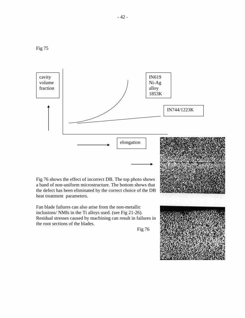
Fig 75
Fig 76 shows the effect of incorrect DB. The top photo shows
a band of non-uniform microstructure. The bottom shows that
the defect has been eliminated by the correct choice of the DB
heat treatment parameters.
Fan blade failures can also arise from the non-metallic
inclusions/ NMIs in the Ti alloys used. (see Fig 21-26).
Residual stresses caused by machining can result in failures in
the root sections of the blades.
Fig 76
cavity
volume
fraction
elongation
IN744/1223K
IN619
Ni-Ag
alloy
1853K

- 43 -
3.17 Engine component failures due to a combination of high temperatures and
stress levels
Figs 70 & 71 show examples of the R-R engines . With increase in long haul flights and
higher pay-loads ( a Boeing 747 fully laden on take-off weighs about 400 Tonnes),
bigger, better engines with higher thrust levels(exceeding 115,000lbs) are constantly
being developed. Fig 77 shows the rise in the turbine entry temperatures.
Fig 77
With entry temperatures approaching ~ 16000 C, the demands placed on the turbine
discs and blades are very severe. The materials chosen must be free of NMIs, must
withstand high temperature oxidation, must have adequate yield and fatigue strength at
these temperatures. In general, a complex alloy mix of Ni, V, Mo, W, Cr is employed to
meet the severe conditions within the engine. The turbine blades used in the high pressure
section of the engine are produced by an investment –type of casting to produce single

- 44 -
crystals, from which the blades are machined out. Fig 78 shows a blade cut at the base to
reveal the channels within to provide air
cooling. The examples shown below have
been given to me during visit to the Turbine
Blade Division of R-R at Bristol.
Fig 78
Fig 79
Fig 80
The root of the
blade is shaped
like a fir tree and
slots within the
turbine disc

- 45 -
Fig 79 & 80 are examples of damage to the high pressure turbine blades. Continued
exposure to a combination of high stress levels and temperatures has led to the shape
distortion to the blade as well as to the breakage at the tips . Fig 81 is an example of
failure within the vents in the intermediate section of the engine . This is primary
damage; secondary damage occurs as the broken fragment spins away with a high
centrifugal velocity and force and impacts and ricochets elsewhere within the engine .
Fig 81
Engine components subjected to a combination of stress and high operating temperatures
fail due to reasons that include- weakened grain boundaries ,excessive grain growth
brought about by the gradual disappearance of the precipitate particles that normally
restrict grain boundary migration
and grain growth.
Fig 82 shows the denuded grain
boundaries, known as
‘precipitate-free zones’, PFZ.
The precipitates seen on the
boundaries have grown in size
during service at the expense of
those that were, at the outset,
uniformly distributed on either
side of the boundaries. As a
consequence, the boundaries are
weakened. Potentially, failure
can occur in service.
Fig 82

- 46 -
Fig 83 ( sourced from the Internet)
The extent of microstructural damage seen at the grain boundaries in Fig 83 is a typical
example of the reasons behind the failure of components as a result of creep . Softening,
shape distortion and eventual fragmenting seen in Figs.79-81 are often attributed to
failure under creep.
3.18 Stress corrosion cracking SCC
A combination of stress and a corrosive environment can lead to SCC. Steel structural
components, reinforcements, turbine rotors, automobile bimetal bearings based on alpha
plus beta type brasses,, high strength aluminium alloys of the 2000 and 7000 series are
examples of materials known to exhibit SCC . Several studies have shown that SCC
takes the form of intergranular cracking. Examples of SCC are shown in Figs 84-86.

- 47 -
Fig 84 . SCC in rotor steels at two applied stress rates /exposed to water at 30 0
C (after
Ramamurthy & Atrens Corrosion Science,52 /2010, Pp1042-1051)
Fig 85 Failure at the grainboundaries
& severe pitting on the grain surfaces.
Fig 86 .a. base alloy/Al-Zn-Mg-Cu-Zr
showing SCC. b. same alloy with
Sc addition showing a ductile fracture
(Bobby Kannan & Raja,Eng. Fracture
Mechanics,77/2010)P249-256
- 48 -
SCC involves slow, environmentally induced crack propagation which may be assisted
by a combination of mechanical and chemical forces. The stresses required are tensile
and relatively small, usually below the yield strength. Given a corrosive environment,
externally applied stresses or residual stresses promote SCC. Cracks nucleate and
propagate at a slow rate; according to R.H.Jones & R.E.Ricker , the rates are ~10 –
9
to 10 – 6
m/s. Pre-existing defects such as NMIs ( discussed in Figs 21-26) can often help
to nucleate the cracks.
It is evident from fig 84 that SCC occurs at all stress rates. Ramamurthy &Atrens note
that the fracture stress decreased slightly with a falling applied stress rate until 0.02
MPa/sec and then decreased significantly with a further fall in the applied stress rate.
They note that SCC velocity is affected by the applied stress rate and the crack tip strain
rate. Preventive measures suggested include a decrease in the magnitude of the stress by
a decrease in the external load or by an increase in the cross-sectional area perpendicular
to the applied stress. A heat treatment to anneal out residual stresses is also
recommended.
Fig 86a (Bobby Kannan & Raja /2010) shows severe intergranular attack in an Al-Zn-
Mg-Cu-Zr alloy. They found that resistance to SCC can be enhanced by additions of Sc
which help to inhibit recrystallisation . This is shown in Fig 86 b which reveals an
essentially ductile fracture.
3.19 Corrosion in the absence of stress; failures in zinc coated sheet steel
components
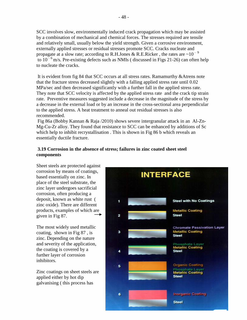
Sheet steels are protected against
corrosion by means of coatings,
based essentially on zinc. In
place of the steel substrate, the
zinc layer undergoes sacrificial
corrosion, often producing a
deposit, known as white rust (
zinc oxide). There are different
products, examples of which are
given in Fig 87.
The most widely used metallic
coating, shown in Fig 87 , is
zinc. Depending on the nature
and severity of the application,
the coating is covered by a
further layer of corrosion
inhibitors.
Zinc coatings on sheet steels are
applied either by hot dip
galvanising ( this process has

- 49 -
many variations) or by electrodeposition involving a soluble zinc anode , an electrolytic
cell and the sheet steel being the cathode). The most widely used hot dip galvanised
product can be seen on the guard rails of roadside bridges, motorway crash barriers, farm
buildings, grain silos, new metal dustbins, etc. The characteristic ‘spangle’ appearance of
the zinc crystals on such products can be seen with the naked eye ( Fig.88).
Fig 88
Relatively smoother zinc coating by electrodeposition has until recently been widely used
for automotive skin planels. When seen under the electron microscope , platelets of zinc
are clearly visible.
Fig 89.
A product that is
widely used in the
roofs and interiors
of buildings, office
furniture and
similar applications
is known as
COLORCOAT. Cut
edges of sheets of
this product often
suffer from
corrosion. An
example is shown
in Figs 90a&b
Fig 90a
(from The Welsh
TechnologyCentre
Centre/ex
CORUS)

- 50 -
Sheet steels used in the manufacture of autobodies need to meet exacting demands since
cars are exposed to a range of severe conditions. The coating must have a good bond with
the steel substrate; this is
especially important during the
forming of door, wing, bonnet and
roof panels in the press shops. At
times, the adhesion of the coating
is poor and defects such as those in
Fig 91&92 appear on the surface .
The reasons for such failures can
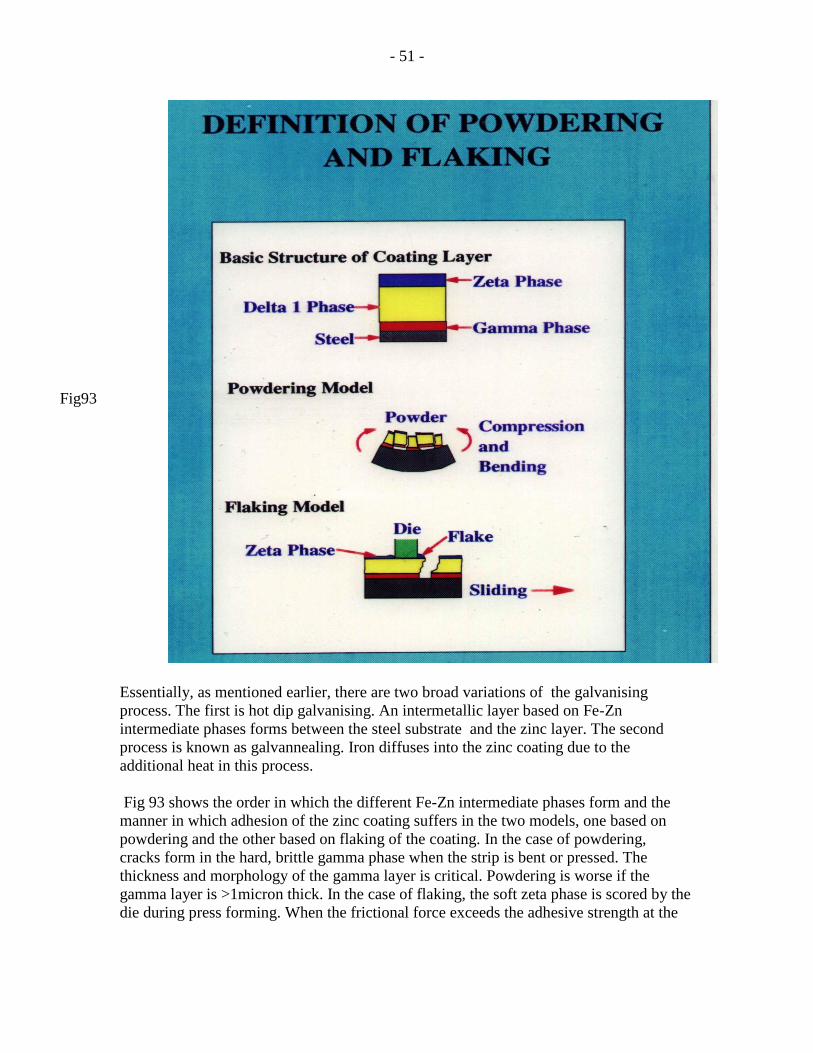
be seen from Fig 93.
Fig 90b
Fig 91
Fig 92
- 51 -
Fig93
Essentially, as mentioned earlier, there are two broad variations of the galvanising
process. The first is hot dip galvanising. An intermetallic layer based on Fe-Zn
intermediate phases forms between the steel substrate and the zinc layer. The second
process is known as galvannealing. Iron diffuses into the zinc coating due to the
additional heat in this process.
Fig 93 shows the order in which the different Fe-Zn intermediate phases form and the
manner in which adhesion of the zinc coating suffers in the two models, one based on
powdering and the other based on flaking of the coating. In the case of powdering,
cracks form in the hard, brittle gamma phase when the strip is bent or pressed. The
thickness and morphology of the gamma layer is critical. Powdering is worse if the
gamma layer is >1micron thick. In the case of flaking, the soft zeta phase is scored by the
die during press forming. When the frictional force exceeds the adhesive strength at the

- 52 -
zinc-coating interface, flaking occurs. The adhesive strength is governed by the thickness
of the gamma phase.
(Figs 87,90 &93 are from the Welsh Technology Centre/CORUS /JACQUI
NORTH/2001)
The most recent information from Tata Steel /Llanwern Works is that galvannealing is not
the preferred route now .Sheet steels for autobodies are produced successfully by hot dip
galvanising. This is achieved by a careful control of the chemical composition of the
steel and the zinc bath as well as the process parameters so as to obtain an optimum
distribution of the various intermediate phases that lie between the steel substrate and the
zinc coating. Electrocoated zinc steels are not widely used at present since the process is
relatively slow and, hence, not ideal for high volume, high tonnage production for the
current automotive sector.
3.20 Surface defects on sheet steels which lead to rejection
Essentially, sheet steels are supplied under two categories; where the surface quality is
not critical since the steels are intended for interior panels on cars, the grade is classified
as ‘general purpose’ GP. For surface-critical applications such as exterior panels on cars,
the grade is classified as ‘full –finished’. The latter grade is very closely watched on the
inspection benches and rejection follows when the sheet surface shows defects such as
those listed below.
Blisters
During steel making, argon gas is blown from the bottom of the vessel in order to agitate
the bath, homogenise the mixing of the alloy additions with the liquid steel and to
promote a temperature uniformity within the bath. On occasions, traces of the gas get
entrapped as the steel is poured into the tundish and as solidification starts. On further
downstream processing, pockets of this gas lead to the formation of blisters. Fig 94.
Fig 94
- 53 -
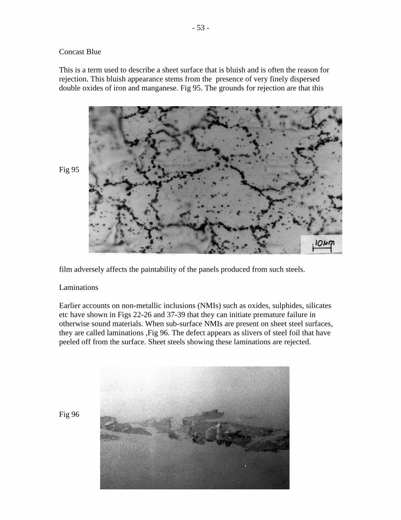
Concast Blue
This is a term used to describe a sheet surface that is bluish and is often the reason for
rejection. This bluish appearance stems from the presence of very finely dispersed
double oxides of iron and manganese. Fig 95. The grounds for rejection are that this
Fig 95
film adversely affects the paintability of the panels produced from such steels.
Laminations
Earlier accounts on non-metallic inclusions (NMIs) such as oxides, sulphides, silicates
etc have shown in Figs 22-26 and 37-39 that they can initiate premature failure in
otherwise sound materials. When sub-surface NMIs are present on sheet steel surfaces,
they are called laminations ,Fig 96. The defect appears as slivers of steel foil that have
peeled off from the surface. Sheet steels showing these laminations are rejected.
Fig 96

- 54 -
Sticker wrench marks
Batch annealing of sheet steels involves annealing stacks of coils of strip that has been
cold reduced to the desire gauge. The cold rolled coils are wound under a given line
tension. Annealing restores the ductility and formability of the steel. During the
prolonged soak at the annealing temperature ( ~7000 C), adjacent laps of the coils stick
together by a process of local welding of the high spots on the surface of the strip. At the
end of annealing, the coils are cooled down, unwrapped and fed into a temper mill which
gives a slight cold rolling reduction , typically, ~0.8%. This is called temper rolling and is
designed to eliminate discontinuous yielding ( see Figs2-5 ). During this process of
unwrapping and feeding into the temper mill, the high spots on the surface that had
welded together during annealing now break free. This results in the formation of marks
on the surface; these are known as sticker wrench marks, Fig 97. Their appearance is
undesirable and this leads to rejection of the steels intended for ‘surface-critical’
applications.
Fig 97

- 55 -
Pinch marks
These may occur when the coil is fed into the cold rolling mill or even the temper mill.
Incorrect feeding, lack of the appropriate line tension or surface irregularities can lead to
these surface marks, Fig 98
Fig 98
The appearance of these marks will lead to the rejection of the relevant portion of the
coil.
Scale on hot rolled coils
Bearing in mind the fact that hot rolling of sheet steels starts at ~ 12000 C ( t=~250mm)
and finishes at ~ 9000
C (t=~1.4mm), the steel is exposed to a very high temperature. This
leads to the formation of a layer of oxides of iron, manganese, etc on the surface. This is
known as scale Fig 99.
Fig 99

- 56 -
The scale is removed by agitating the hot rolled coil in a bath of dilute acid, typically
hydrochloric acid. In general, the process is highly successful and the strip is free of scale
and other contaminants prior to being cold rolled on the five or six stand , four high
tandem mill. However, on occasions, the surface is chemically reactive with the presence
of hydrogen that remains essentially dormant. When the steels is used for enamelling
applications, the nascent hydrogen can affect the coating of enamel; with time, this can
lead to a problem known as fish scaling.
3.21 Incorrect processing temperatures can lead to rejection of materials
Temperature control at all stages of processing is crucial. One of the best examples to
illustrate this point is the case of hot rolling of steel strip. Typically, the slabs (~250 mm
thick) enter the hot mill at ~1200 0 C and leave it , for example, at 900
0 C ( ~1.4mm
thick). At an intermediate stage, the steel is ~ 100 mm thick and is coiled in the unit
known as the coil box. Fig100. Further hot rolling down to the final gauge is carried out
Fig 100 Fig 101 Fig 102
in the finishing mill ,Figs 101-103
, Fig 103.
- 57 -
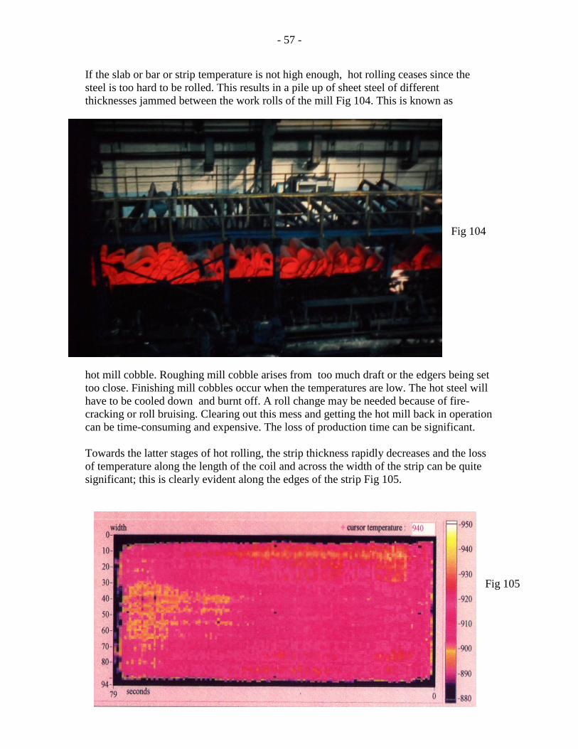
If the slab or bar or strip temperature is not high enough, hot rolling ceases since the
steel is too hard to be rolled. This results in a pile up of sheet steel of different
thicknesses jammed between the work rolls of the mill Fig 104. This is known as
Fig 104
hot mill cobble. Roughing mill cobble arises from too much draft or the edgers being set
too close. Finishing mill cobbles occur when the temperatures are low. The hot steel will
have to be cooled down and burnt off. A roll change may be needed because of fire-
cracking or roll bruising. Clearing out this mess and getting the hot mill back in operation
can be time-consuming and expensive. The loss of production time can be significant.
Towards the latter stages of hot rolling, the strip thickness rapidly decreases and the loss
of temperature along the length of the coil and across the width of the strip can be quite
significant; this is clearly evident along the edges of the strip Fig 105.
Fig 105

- 58 -
Fig 105 can be interpreted as follows.
1.the edges are at ~880 0 C or less. This means that the parent austenite would have
partially transformed to ferrite. Once transformed, these ferrite grains continue to grow.
2.the regions away from the edges are still at a temperature ( >890 0 C)high enough for
the austenite to remain untransformed.
3. when the strip eventually reaches the water sprays at the ‘run-out’ table, these austenite
grains in the regions away from the edges now transform to fine ferrite grains.
4. the outcome is a mixture of large ferrite grains at the edges and fine ferrite grains away
from the edges.
5. Fig 106 shows a part of the microstructure on the plane of the sheet ie across the sheet
width. .The very large ferrite grains are at the edge ( bottom of Fig 106) and the fine
ferrite grains are seen in the region away from the edge. The same pattern occurs at the
other edge.
Fig 106
The consequence of this grain size variation across the width of the strip is evident when the hot
rolled sheet is later cold rolled in the cold mill. The larger grains at the edges are softer and
hence, are cold rolled more than the regions away from the edges. This over-rolling in the cold
mill can lead to the
formation of wavy edges
seen in Fig 107. The strip
would hence be rejected
due to poor shape.
Fig 107

- 59 -
3.22 Examples of failures in composite materials
There are several types of composites used in the industry. In general, a relatively soft and
ductile matrix provides the base into which are embedded different types of hard fibres based
on , for example, carbon or ceramic materials. The nature of the environment determines the
choice of the matrix , the type of fibres and, whether the fibres are aligned in relation to the
principal stress axis. Aligning the fibres helps to control the propagation of the cracks since
they absorb a part of the energy of deformation. A carbon-epoxy resin combination absorbs
more energy than steel.
With high temperature applications such as in aerospace, the issues are; temperatures can be up
to 1500 0
C and above., a service time of ~1500 hours and an oxidising atmosphere. Vacancy
diffusion at such temperatures can be very high, stress-aided diffusion needs to be prevented
and this requires that the fibres are aligned and that dislocation multiplication is prevented. To
stop dislocation motion, a high enough Pierels stress is needed. In Formula 1 racing cars,
carbon fibre-epoxy resin panels are used with the fibres being aligned to produce laminate
sandwiches.
Examples of alumina fibres are shown in Fig 108.
Fig 108 Fig 109
At high magnification, Fig 109, the alumina fibres are clearly seen to be recrystallised.
The bonding of the fibres to the resin matrix is a critical issue. In the absence of a good bond,
fibre-pullout can occur which can lead to the failure of the component. Equally, there are
instances where a certain level of fibre-pullout is deliberately allowed for since this helps to
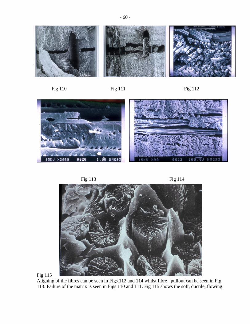
absorb the energy of deformation. Examples of failures are shown in Figs 110-115.
- 60 -
Fig 110 Fig 111 Fig 112
Fig 113 Fig 114
Fig 115
Aligning of the fibres can be seen in Figs.112 and 114 whilst fibre –pullout can be seen in Fig
113. Failure of the matrix is seen in Figs 110 and 111. Fig 115 shows the soft, ductile, flowing

- 61 -
nature of the failure in the matrix; in contrast, the hard fibre has failed in a brittle manner. In
some respects, these examples of ductile and brittle failures are similar to those seen earlier in
metallic materials, Figs 20-22 and Fig 32.
4. Remarks in conclusion
This compilation is merely a small window through which the reader can get some
appreciation of why materials and components fail in industry. Over one hundred
photographs, illustrations and other data have been provided in order for the student to
identify the nature and appearance of the defect, recognise it if it occurs in the future,
understand why this occurs, what will be consequences if it goes undetected and what can
be done to prevent the recurrence of it in the future. It is hoped that this compilation will
prove to be a source of reference to the broad spectrum of fractures, failures and
rejections of engineering materials and components.
5. Acknowledgements
The illustrations given here have been drawn from several sources. Wherever relevant,
these sources have been mentioned. A significant amount of data has been obtained
during my visits to the Rolls-Royce plants at Barnoldwick, Lancashire, Bristol and
Derby as well as to the Customer Support facility of Rolls-Royce in London. Information
and data have also been collected during my visits to the Ford’s R & D centre based in
Dunton, Essex. Some of the illustrations and examples cited have been extracted from
my reports and notes made during my days at the Welsh Technology Centre, ( formerly
Corus/ now Tata Steel) Port Talbot. Finally, the few remaining examples have been
derived from the internet; references to these are given in the text.
I place on record my gratitude to the people in the above institutions who gave me the
information that enabled me to undertake this compilation.