Example: Full-bridge parallel resonant inverter 2. Steady-state solution
22
Fundamentals of Power Electronics 1 Chapter 19: Resonant Conversion resonant inverter 1. Construct steady-state plus small- signal phasor model
-
Upload
craig-howe -
Category
Documents
-
view
54 -
download
2
description
Example: Full-bridge parallel resonant inverter 1. Construct steady-state plus small-signal phasor model. Example: Full-bridge parallel resonant inverter 2. Steady-state solution. Example: Full-bridge parallel resonant inverter 3. Small-signal perturbation in output phasor. - PowerPoint PPT Presentation
Transcript of Example: Full-bridge parallel resonant inverter 2. Steady-state solution

Fundamentals of Power Electronics 1 Chapter 19: Resonant Conversion
Example: Full-bridge parallel resonant inverter1. Construct steady-state plus small-signal phasor model
Fundamentals of Power Electronics 2 Chapter 19: Resonant Conversion
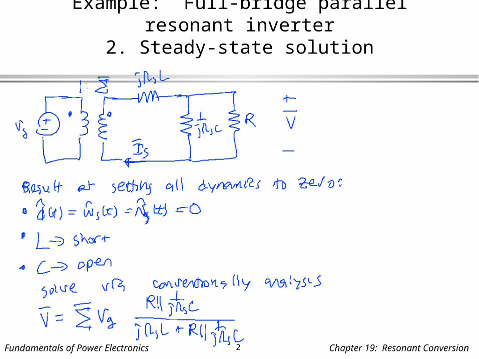
Example: Full-bridge parallel resonant inverter2. Steady-state solution
Fundamentals of Power Electronics 3 Chapter 19: Resonant Conversion
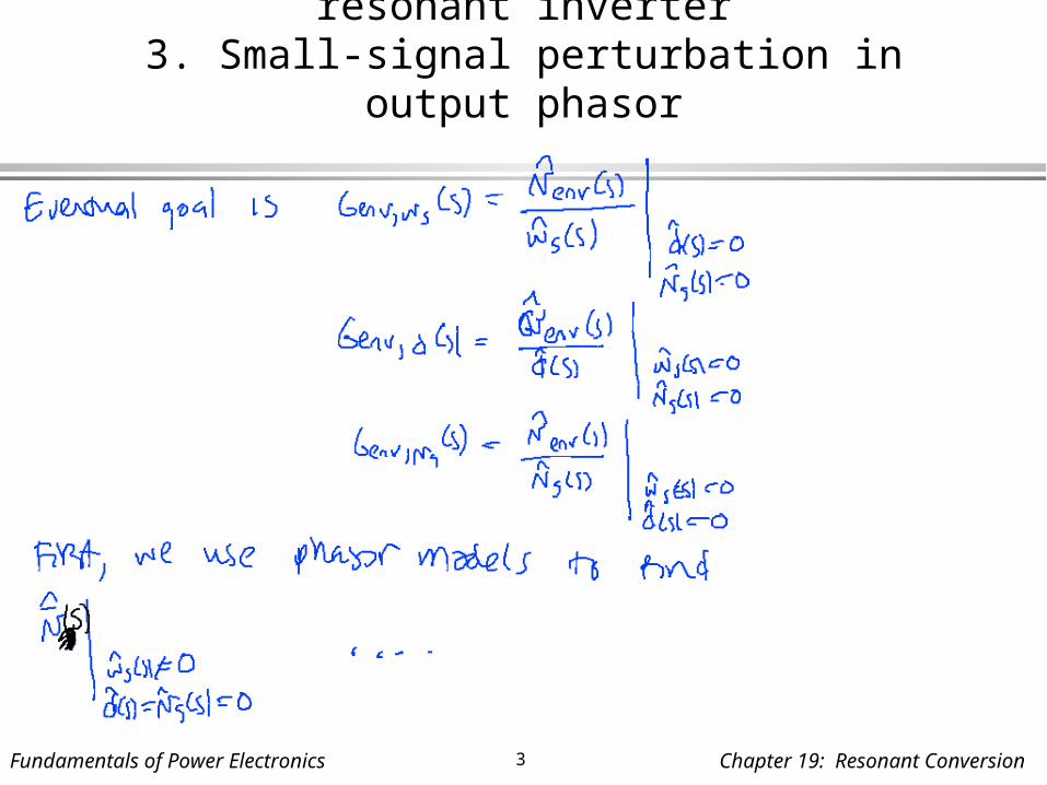
Example: Full-bridge parallel resonant inverter3. Small-signal perturbation in output phasor

Fundamentals of Power Electronics 4 Chapter 19: Resonant Conversion
Example: Full-bridge parallel resonant inverter3. Small-signal perturbation in output phasor

Fundamentals of Power Electronics 5 Chapter 19: Resonant Conversion
Recovering the actual output envelope

Fundamentals of Power Electronics 6 Chapter 19: Resonant Conversion
Recovering the actual output envelope
Fundamentals of Power Electronics 7 Chapter 19: Resonant Conversion
Recovering the actual output envelope
Fundamentals of Power Electronics 8 Chapter 19: Resonant Conversion
Recovering the actual output envelope

Fundamentals of Power Electronics 9 Chapter 19: Resonant Conversion
Simulation using SPICE
Fundamentals of Power Electronics 10 Chapter 19: Resonant Conversion
SPICE inductor model
Fundamentals of Power Electronics 11 Chapter 19: Resonant Conversion
SPICE models

Fundamentals of Power Electronics 12 Chapter 19: Resonant Conversion
SPICE models
Fundamentals of Power Electronics 13 Chapter 19: Resonant Conversion
Example: Full-bridge parallel resonant inverterSPICE-compatible model

Fundamentals of Power Electronics 14 Chapter 19: Resonant Conversion
Recovering the actual output envelope in SPICE

Fundamentals of Power Electronics 15 Chapter 19: Resonant Conversion
Recovering the actual output envelope in SPICE
Fundamentals of Power Electronics 16 Chapter 19: Resonant Conversion
Recovering the actual output envelope in SPICE

Fundamentals of Power Electronics 17 Chapter 19: Resonant Conversion
Recovering the actual output envelope in SPICE

Fundamentals of Power Electronics 18 Chapter 19: Resonant Conversion
Recovering the actual output envelope in SPICE

parallel resonant inverter
*PARAMETERS AND NODESETS
*main circuit parameters.param L=627u.param Cp=7.9n.param Vg = 150.param R=400.param fs=86k.param ws=540k;.param Vin = 191
*steady-state switching frequency.nodeset v(w)=540k
*voltages and currents.nodeset i(L_re)=0.5209.nodeset i(L_im)=-0.8382.nodeset v(out_re)=-92.99.nodeset v(out_im)=-176.5.nodeset v(outi)=0.6536.nodeset v(outv)=199.5.nodeset v(in_im)=0.nodeset v(in_re)=191.nodeset v(xl_im)=0.nodeset v(xl_re)=191.nodeset v(in_rex)=191.nodeset v(out_imdum)=0.nodeset v(out_redum)=0
*CIRCUIT CONSTRUCTION
*real part
V_re in_rex 0 dc 191 ac 0V_rex in_re in_rex sin(0 0 1000 0 0) ac 0L_re in_re xl_re {L}EXL_re xl_re out_re value {-v(w)*{L}*i(EXL_im)}Cp_re out_re 0 {Cp} Gcp_re out_re 0 value {-v(w)*{Cp}*v(out_im)}Rp_re out_re 0 10g
*add dummy voltage to measure currentvdum_re out_re out_redum 0R_re out_redum 0 {R}
*imaginary part
V_im in_im 0 dc 0 ac 0L_im in_im xl_im {L}EXL_im xl_im out_im value {v(w)*{L}*i(EXL_re)}Cp_im out_im 0 {Cp} Gcp_im out_im 0 value {v(w)*{Cp}*v(out_re)}Rp_im out_im 0 10g
*add dummy voltage to measure currentvdum_im out_im out_imdum 0R_im out_imdum 0 {R}
*frequency perturbation vw w 0 {ws} ac 1Rph w 0 1meg
*EXTRACT ENVELOPE
Evout outv 0 value {sqrt(v(out_re)*v(out_re)+v(out_im)*v(out_im))}Rvout outv 0 100Eiout outi 0 value {sqrt(i(vdum_re)*i(vdum_re)+i(vdum_im)*i(vdum_im))}Riout outi 0 100
*analysis setup.op.ac dec 201 1000 300k*.tran 1n 500u 0 0.1u
.probe
.END

Fundamentals of Power Electronics 20 Chapter 19: Resonant Conversion
Genv,ws(s) from SPICE

Fundamentals of Power Electronics 21 Chapter 19: Resonant Conversion
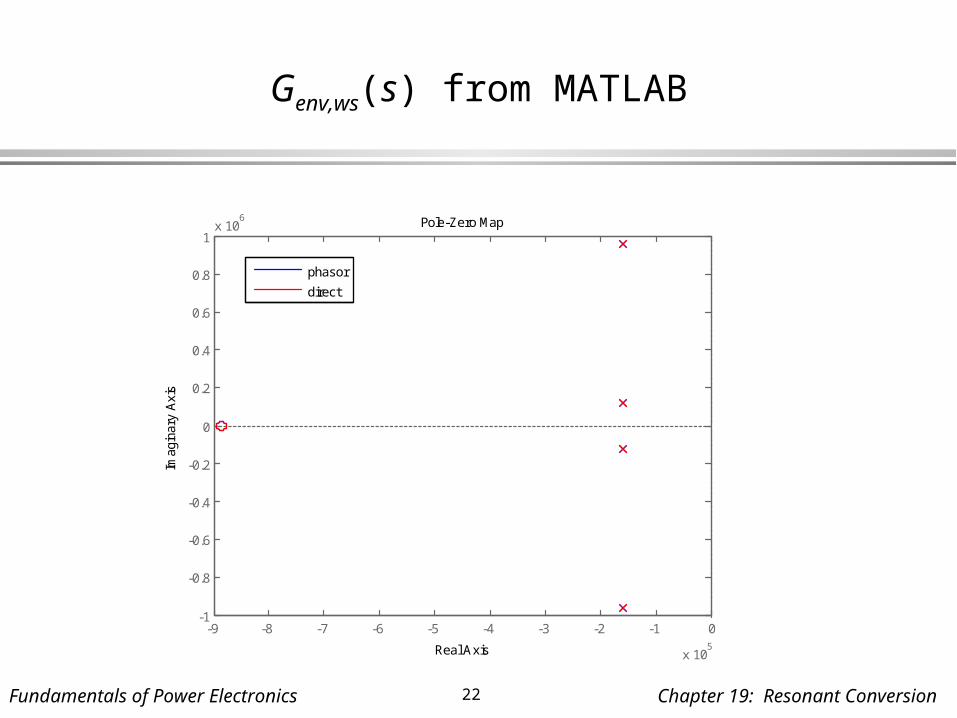
Genv,ws(s) from MATLAB
-110
-100
-90
-80
-70
-60From: w s-hat To: vout-env
Mag
nitu
de (
dB)
100
101
102
103
104
105
-180
-90
0
90
180
Pha
se (
deg)
Bode Diagram
Frequency (Hz)
phasor
direct
Fundamentals of Power Electronics 22 Chapter 19: Resonant Conversion
Genv,ws(s) from MATLAB
-9 -8 -7 -6 -5 -4 -3 -2 -1 0
x 105
-1
-0.8
-0.6
-0.4
-0.2
0
0.2
0.4
0.6
0.8
1x 10
6
Pole-Zero Map
Real Axis
Imag
inar
y A
xis
phasor
direct


![A High-Frequency Resonant Inverter Topology with Low ... · PDF fileA High-Frequency Resonant Inverter Topology with ... the well-known class E inverter [12] uses resonant operation](https://static.fdocuments.net/doc/165x107/5a9f06527f8b9a76178c370c/a-high-frequency-resonant-inverter-topology-with-low-high-frequency-resonant.jpg)