Examination of the Fatigue Life under Combined Loading of Specimens€¦ · Examination of the...
8
Applied and Computational Mechanics 2 (2008) 37–45 Examination of the Fatigue Life under Combined Loading of Specimens F. Fojt´ ık a,∗ , J. Fuxa a a Faculty of Mechanical Engineering, V ˇ SB – Technical University of Ostrava, 17. listopadu 15, 708 33 Ostrava-Poruba, Czech Republic Received 25 August 2008; received in revised form 6 October 2008 Abstract This contribution describes experimental results under combined loading of specimens manufactured from com- mon construction steel 11523. Specimens were gradually loaded by amplitude of the torque, then by combination of torque and tension prestress. The last set of specimens was loaded in combination of torque and inner over- pressure. To obtain the required input values the stress-strain analysis of specimens by finite element method in software Ansys was performed within the last experiment. For evaluation of the results the Fuxa’s criterion was applied. The performed experiments and their results embody a good agreement with bellow mentioned conju- gated strength criterion. The experiments were performed on reconstructed testing machine equipped by pressure chamber. c 2008 University of West Bohemia in Pilsen. All rights reserved. Keywords: combined loading, high-cycle fatigue, experiment, multi-axial fatigue, mean stress effect 1. Introduction To verify the developed multi-axial Fuxa’s conjugated strength criterion and to determine the proper constants the new jig was developed which generalizes the possibilities of reconstructed testing machine SHENCK typer PWXN [1]. In this case the testing machine was newly equip- ped by pressure chamber which makes possible to load the specimen by constant inner over- pressure (in the range 0 to 70 MPa) in addition with torque amplitude. It is also possible to add the constant tension/pressure pre-stress into the system and to realize the proper combinations of stress states. 2. Experimental Device For material testing under combined loading in the region of high-cycle fatigue and for veri- fication of Fuxa’s conjugated strength criterion was reconstructed the testing device SHENCK type PWXN [1, 2]. The new conception of the testing device changes the loading character of the specimen from deformation-controlled to force-controlled — see fig. 1. The base of the testing machine is the frame 1 with gear box which is driven by asyn- chronous electromotor. Required torque is gained by the acceleration of driven part and by bal- ance wheel located in measuring box 2. Axial tension/pressure force is gained by straight-line hydro motor 3 connected with hydraulic aggregate. Newly is the testing machine equipped by pressure chamber 4 which is connected with multiplier and hydraulic aggregate. The measured ∗ Corresponding author. Tel.: +420 597 323 292, e-mail: [email protected]. 37
-
Upload
truongcong -
Category
Documents
-
view
220 -
download
0
Transcript of Examination of the Fatigue Life under Combined Loading of Specimens€¦ · Examination of the...
Applied and Computational Mechanics 2 (2008) 37–45
Examination of the Fatigue Life under CombinedLoading of Specimens
F. Fojtıka,∗, J. Fuxaa
aFaculty of Mechanical Engineering, VSB – Technical University of Ostrava, 17. listopadu 15, 708 33 Ostrava-Poruba, Czech Republic
Received 25 August 2008; received in revised form 6 October 2008
Abstract
This contribution describes experimental results under combined loading of specimens manufactured from com-mon construction steel 11523. Specimens were gradually loaded by amplitude of the torque, then by combinationof torque and tension prestress. The last set of specimens was loaded in combination of torque and inner over-pressure. To obtain the required input values the stress-strain analysis of specimens by finite element method insoftware Ansys was performed within the last experiment. For evaluation of the results the Fuxa’s criterion wasapplied. The performed experiments and their results embody a good agreement with bellow mentioned conju-gated strength criterion. The experiments were performed on reconstructed testing machine equipped by pressurechamber.c© 2008 University of West Bohemia in Pilsen. All rights reserved.
Keywords: combined loading, high-cycle fatigue, experiment, multi-axial fatigue, mean stress effect
1. Introduction
To verify the developed multi-axial Fuxa’s conjugated strength criterion and to determine theproper constants the new jig was developed which generalizes the possibilities of reconstructedtesting machine SHENCK typer PWXN [1]. In this case the testing machine was newly equip-ped by pressure chamber which makes possible to load the specimen by constant inner over-pressure (in the range 0 to 70 MPa) in addition with torque amplitude. It is also possible to addthe constant tension/pressure pre-stress into the system and to realize the proper combinationsof stress states.
2. Experimental Device
For material testing under combined loading in the region of high-cycle fatigue and for veri-fication of Fuxa’s conjugated strength criterion was reconstructed the testing device SHENCKtype PWXN [1, 2]. The new conception of the testing device changes the loading character ofthe specimen from deformation-controlled to force-controlled — see fig. 1.
The base of the testing machine is the frame 1 with gear box which is driven by asyn-chronous electromotor. Required torque is gained by the acceleration of driven part and by bal-ance wheel located in measuring box 2. Axial tension/pressure force is gained by straight-linehydro motor 3 connected with hydraulic aggregate. Newly is the testing machine equipped bypressure chamber 4 which is connected with multiplier and hydraulic aggregate. The measured
∗Corresponding author. Tel.: +420 597 323 292, e-mail: [email protected].
37

F. Fojtık et al. / Applied and Computational Mechanics 2 (2008) 37–45
Fig. 1. Experimental device
values of the torque, axial force and inner overpressure are evaluated in software LabVIEW8.0.1. [4].
The new conception of the testing device is patented as: Experimental Device for combinedloading of specimens, Nr. 17286 (2007).
3. Experiment — alternating torsion
Specimens manufactured from steel 11523, melting nr. T18556 whose parameters are in fig. 2were loaded by amplitude of torque in the condition of alternating cycle. The amplitude oftorque was gradually decreased until the limit 107 cycles was reached.
Fig. 2. Specimen
The results are placed in tab. 1. In the fig. 3 can be seen measured values, Baskin’s approxi-mation curves (1) and Fuxa’s approximation curves (2) [5]. Point of crack initiation under statictorsion was measured by reconstructed Testing machine INOVA in the institute lab.
Basquin’s approximation:τa = τ ′
f · (2Nf)b , (1)
where τ ′f (758,75 MPa) is the fatigue strength and b (−0.083 6) is fatigue strength coefficient.
38

F. Fojtık et al. / Applied and Computational Mechanics 2 (2008) 37–45
Table 1. Experimental results for alternating torsion
Specimen Nr. Stress amplitude Number of cycles Notesτa [MPa]
1 250 267 8002 224 1 238 0003 221 1 539 7004 215 1 620 0005 200.5 3 547 0006 196 10 103 000 No crack generated7 193 10 356 000 No crack generated8 546 0.25
Fig. 3. W – curve for alternating torsion
Fuxa’s approximation:
τaF =τf + τC
2+
τf − τC
2· cos
{π ·[
log (4 · Nf )
log (4 · NC)
]a1}
, (2)
for Nf in interval [1/4; NC ] and τaF in interval [τf ; τC ].τf (546 MPa) is a value of real shear strength, τC (197 MPa) is the stress at the fatigue
limit, NC (9 130 000) is number of cycles at the fatigue limit, a1 (1.324) is constant, τaF is thelimit stress amplitude under alternating torsion and Nf is the limit number of cycles until crackinitiation.
4. Experiment — alternating torsion and tension prestress
The specimens according fig. 4 were used for this way of loading. Those specimens are manu-factured from the same material and melting as in the previous case. Every series of specimenswas loaded by different constant axial tension stress. For given tension stress value was chosen
39

F. Fojtık et al. / Applied and Computational Mechanics 2 (2008) 37–45
the torque amplitude which was the specimen loaded until the crack initiation by. This am-plitude was gradually decreased until the value when was the specimen able to endure 107 ofcycles.
Fig. 4. Specimen for combined loading torsion — tension
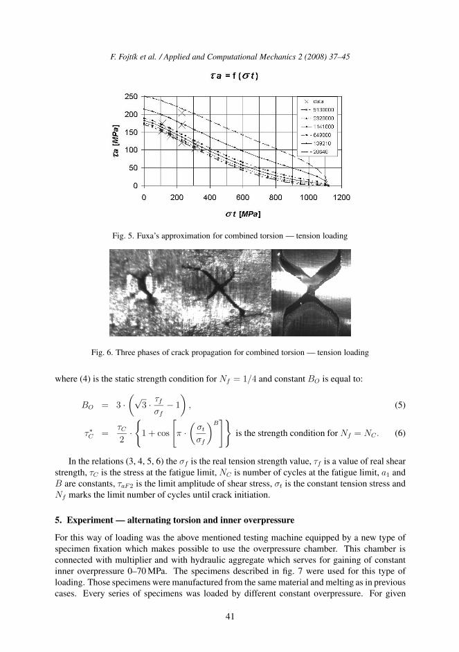
The results of those experiments are mentioned in tab. 2. The experimental results arealso shown in fig. 5 and approximated by lower described Fuxa’s approximation (3, 4, 5, 6)which takes the influence of mean stress into account. Particular approximations are based onmeasured number of cycles which is mentioned in fig. 2.
Table 2. Experimental results for alternating torsion and tension prestress
Specimen Nr. Tension Stress Stress amplitude Number of Cycles Notes[MPa] τa [MPa]
1 110 174 649 0002 110 154.2 11 500 000 No crack generated3 160.4 148 2 320 0004 160.4 139.5 11 600 000 No crack generated5 228.4 203.7 28 6406 228.2 170 139 2107 228.4 120 10 800 000 No crack generated8 310 116 1 141 0009 310 104.7 11 300 000 No crack generated
On the fig. 6 are displayed three phases of crack propagation for described combined load-ing.
Fuxa’s approximation with influence of mean stress:
τaF2 =τ ∗f + τ ∗
C
2+
τ ∗f − τ ∗
C
2· cos
{π ·[
log (4 · Nf )
log (4 · NC)
]a1}
, (3)
τ ∗f =
1√3·(
(√
3 · τf )2 − 2 ·√
3 · τf · BO · σt
3+ σ2
t ·B2
O
9− σ2
t
)1/2
, (4)
40
F. Fojtık et al. / Applied and Computational Mechanics 2 (2008) 37–45
Fig. 5. Fuxa’s approximation for combined torsion — tension loading
Fig. 6. Three phases of crack propagation for combined torsion — tension loading
where (4) is the static strength condition for Nf = 1/4 and constant BO is equal to:
BO = 3 ·(√
3 · τf
σf− 1
), (5)
τ ∗C =
τC
2·{
1 + cos
[π ·(
σt
σf
)B]}
is the strength condition for Nf = NC . (6)
In the relations (3, 4, 5, 6) the σf is the real tension strength value, τf is a value of real shearstrength, τC is the stress at the fatigue limit, NC is number of cycles at the fatigue limit, a1 andB are constants, τaF2 is the limit amplitude of shear stress, σt is the constant tension stress andNf marks the limit number of cycles until crack initiation.
5. Experiment — alternating torsion and inner overpressure
For this way of loading was the above mentioned testing machine equipped by a new type ofspecimen fixation which makes possible to use the overpressure chamber. This chamber isconnected with multiplier and with hydraulic aggregate which serves for gaining of constantinner overpressure 0–70 MPa. The specimens described in fig. 7 were used for this type ofloading. Those specimens were manufactured from the same material and melting as in previouscases. Every series of specimens was loaded by different constant overpressure. For given
41

F. Fojtık et al. / Applied and Computational Mechanics 2 (2008) 37–45
constant inner overpressure value was chosen the torque amplitude which was the specimenloaded until the crack initiation by. This amplitude was gradually decreased until the valuewhen was the specimen able to endure 107 of cycles. The results of those experiments arementioned in tab. 3.
Fig. 7. Specimen for combined torsion — inner overpressure loading
Table 3. Experimental results for alternating torsion and tension prestress
Specimen Overpressure σt = σa + σt1 Stress Number NotesNr. amplitude of cycles
[MPa] [MPa] [MPa]1 13 155.1 158.3 496 9002 13 155.1 142.5 11 640 000 No crack generated3 27 321.1 149 204 0004 27 321.1 142.5 311 5605 27 321.1 104.6 2 013 0006 27 321.1 91.6 10 118 800 No crack generated
From the evaluation of results can be observed the significant value of circumferential stressσt1 and of axial stress σa at the surface of specimen. It is not easy to determine those two stressesanalytically due to the complicated shape of specimen and face of acting inner overpressure.Hence this stress state had to be determined by finite element method in software ANSYS.
The static analysis was performed, where 1/4 of specimen was modeled, the SOLID element186 was use, the material parameters was obtained on the base of tensile test. The boundaryconditions are chosen so that the resting 3/4 of specimen is compensated by symmetry andfurther one point of specimen face is fixed in three directions (x, y, z). Opposite end of thespecimen is free. On the relevant length the inner overpressure was applied. This length resultsfrom the dimensions of testing jig. Results for given overpressure are in tab. 3. Results ofcircumferential and axial stresses in MPa, obtained from FEM analysis for inner overpressure13 MPa, are on fig. 8.
42

F. Fojtık et al. / Applied and Computational Mechanics 2 (2008) 37–45
Fig. 8. Circumferential and axial stresses for inner overpressure 13 MPa
Experimental results obtained from performed experiments and computation are on fig. 9.Those results are approximated by already mentioned Fuxa’s approximation (3, 4, 5, 6) whichtakes into account the influence of mean stress. For from inner overpressure obtained stressstate it is necessary to adjust the relations (4) Mentioned equation can be written as follows:
τ∗f =
1√3·(
(√
3 · τf )2 − 2 ·√
3 · τf · BO · (σt1 + σa) /3
+ (σt1 + σa)2 · B2
O/9 − σ2t1 + σt1 · σa + σ2
a
)1/2
(7)
This equation is based on reference stresses [3] and on the stress state analysis for givenloading case.
Particular approximations result from measured number of cycles written in tab. 3. On thebase of fig. 9 can be compared the measured data at the fatigue limit obtained from previousexperiment. The good agreement with proposed approximation can be seen. On the fig. 10 arementioned three different types of failures and the crack propagation for different amplitudes ofloading and reached number of cycles.
Fig. 9. Fuxa’s approximation for combined torsion — inner overpressure loading
43

F. Fojtık et al. / Applied and Computational Mechanics 2 (2008) 37–45
Fig. 10. Three types of crack propagations for different ways of loadings
6. Conclusion
The reconstructed testing machine equipped by overpressure chamber is briefly described inthis contribution. Further are mentioned three types of experiments performed at the specimensmade from steel 11523 melting T18556.
First experiment — alternating torsion. Obtained results are approximated by Basquin’s andFuxa’s approximation. The Fuxa’s approximation embodies a good agreement with experiment.The Basquin’s approximation does not take into account the value of real shear strength — seeFig. 3.
Second experiment — combined loading by amplitude of torque and by constant axial ten-sion force. The results are successfully approximated by Fuxa’s approximation with the influ-ence of mean stress. Also here the Fuxa’s approximation embodies the good agreement withexperiment — see Fig. 5. The constants of strength criterion were tuned on this experiment.
Third experiment — combined loading by the amplitude of torque and by inner overpres-sure. Appropriate circumferential and axial stresses (mentioned in Tab. 3) are obtained by finiteelement method and the modification of Fuxa’s approximation is mentioned. The experimentalresults are approximated by Fuxa’s approximation whose constants result from previous exper-iment. The good agreement can be seen here and hence it is possible to state the appropriateconstant tuning for further possible combined loading — see fig. 9. Described Fuxa’s approx-imation is a part of conjugated stress criterion which is based on the conception of referencenormal and reference shear stresses, see [3] for more details.
Acknowledgements
The paper was created under support of GACR, project no: 101/08/P141.
References
[1] F. Fojtık, The Experimental Machine for the Multiaxis Fatigue Testing of Material, DissertationThesis, FS VSB-TU Ostrava, 2007.
[2] F. Fojtık, The Fatigue Testing Machine and Experiment, In: Applied Mechanics 2008, Wisla,Polsko, 2008.
[3] J. Fuxa, R. Kubala, F. Fojtık, Idea of Conjugated Strength, In: Experimental Stress Analysis 2006,Cerveny Klastor, Slovensko, 2006, pp. 125–130.
[4] Fuxa, J., Fojtık, F., Kubala, R., Torque machine fit for high cycle fatigue of material testing, In:Experimental Stress Analysis 2007, Hotel Vyhledy. 2007.
[5] J. Fuxa, R. Kubala, F. Fojtık, Z. Poruba, Reconstruction of the Torque Test Machine and ItsUtilization for Strength Criterion Searching In: Experimental Stress Analysis 2005, Skalsky dvur,2005.
44