
Ex ecutive Summ ar ry - Karnataka State Pollution Control …kspcb.kar.nic.in/PH/ES EIA Karnataka...
34
En Integ (Mad Envotech (A Subsi nvironm grated W danhatti Project P h Waste M diary of SM Ex mental Im Waste M & Pitch Dis Proponent Manageme MS Envocar xecu mpact A Managem hguntrah strict, a : ent Limited re Limited) utive Of Assessm ment fac hali Vill and Karn d ) 304 & Comm Pho e Su ment Stu cility co lage, M nataka.) E EQM & 305 Rishabh munity Centre one: 011 – 300 umm dy of Pr mprisin Malur Ta ) EIA Consu MS INDIA h Corporate T e, Karkardoom 003200; 3000 22374775 mar roposed ng of TS aluk, Ko ultant: PVT. LTD Tower, Plot N ma, Delhi – 1 03218; Fax: 01 ry d DF olar D No. 16, 110092. 11—
Transcript of Ex ecutive Summ ar ry - Karnataka State Pollution Control …kspcb.kar.nic.in/PH/ES EIA Karnataka...
P A G E | 1
EnInteg(Mad
Envotech(A Subsi
nvironmgrated Wdanhatti
Project Ph Waste Mdiary of SM
Ex
mental ImWaste M
& PitchDis
Proponent
ManagemeMS Envocar
xecu
mpact AManagem
hguntrahstrict, a
: ent Limitedre Limited)
utive
Of
Assessmment fachali Vill
and Karn
d )
304 &Comm
Pho
e Su
ment Stucility colage, Mnataka.)
E
EQM
& 305 Rishabhmunity Centreone: 011 – 300
umm
dy of Prmprisin
Malur Ta)
EIA Consu
MS INDIA
h Corporate Te, Karkardoom003200; 3000
22374775
mar
roposedng of TSaluk, Ko
ultant:
PVT. LTD
Tower, Plot Nma, Delhi – 1
03218; Fax: 01
ry
d DF
olar
D
No. 16, 110092. 11—
P A G E | 2
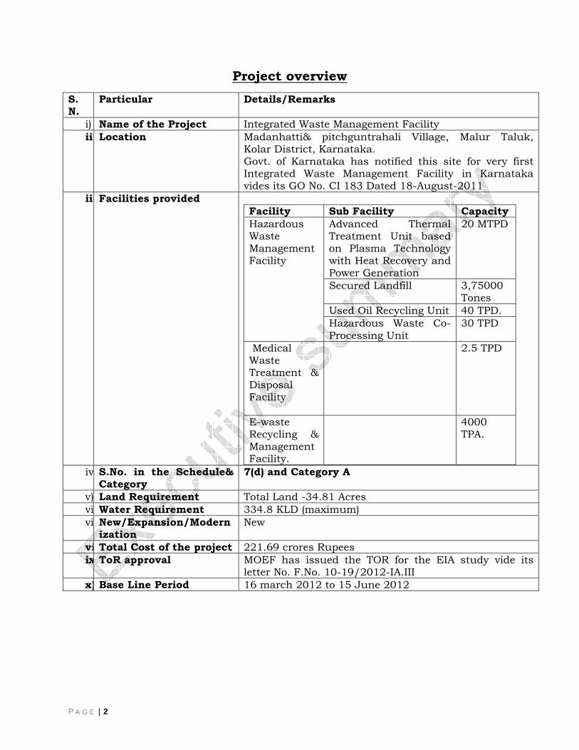
Project overview S. N.
Particular Details/Remarks
i) Name of the Project Integrated Waste Management Facility ii) Location Madanhatti& pitchguntrahali Village, Malur Taluk,
Kolar District, Karnataka. Govt. of Karnataka has notified this site for very first Integrated Waste Management Facility in Karnataka vides its GO No. CI 183 Dated 18-August-2011
iii Facilities provided Facility Sub Facility Capacity Hazardous Waste Management Facility
Advanced Thermal Treatment Unit based on Plasma Technology with Heat Recovery and Power Generation
20 MTPD
Secured Landfill 3,75000 Tones
Used Oil Recycling Unit 40 TPD. Hazardous Waste Co-Processing Unit
30 TPD
Medical Waste Treatment & Disposal Facility
2.5 TPD
E-waste Recycling & Management Facility.
4000 TPA.
iv S.No. in the Schedule& Category
7(d) and Category A
v) Land Requirement Total Land -34.81 Acres vi Water Requirement 334.8 KLD (maximum) vi New/Expansion/Modern
ization New
vi Total Cost of the project 221.69 crores Rupees ix ToR approval MOEF has issued the TOR for the EIA study vide its
letter No. F.No. 10-19/2012-IA.III x) Base Line Period 16 march 2012 to 15 June 2012
P A G E | 3
E. 1. Project Proponent
Envotech Waste Management Limited is a Special purpose vehicle of SMS Envocare Limited of SMS infrastructure Limited Group and Nviro Element Pvt Ltd. SMS Infrastructure Ltd. (SMSIL) is a leading company for infrastructure development, Environment & Clean Energy Projects with the track record of Quality & Technical engineering capabilities since last 47 years having its head office in Nagpur. Various projects of international standard are been successfully erected and executed under Environment and Clean Energy Sector.
The SMSIL believes in adopting the best eco-friendly technology available world over for the scientific disposal of wastes and specializes in treatment and disposal of hazardous solid and liquid waste using environmentally sound methods.
SMSILis pioneer in establishing the first-of-its kind Plasma Gasification based Hazardous Waste Management.
Various projects of international standard are being successfully erected and executed under Environment and clean energy sector.
Nviro Elements Pvt. Ltd., Bangalore is one of the prominent company in the Envotech Waste Management Limited which is professionally managed companydeliveringhigh quality service in the field of Environmental Consultancy, Engineering and Management with a cumulative experience of more than 5 decades in Consultancy, Design, Engineering, Execution & Commissioning of Sewage Treatment Plants, Effluent Treatment Plants, Air Pollution Control Equipment’s etc.
E. 2. Regulatory Framework
As per the Ministry of Environment & Forests (MoEF), Government of India EIA Notification 2006 and as amended on December 1, 2009; the proposed ‘Common Hazardous Waste Treatment & Disposal Facility’ has to take environmental clearance prior to commissioning of the plant. The proposed project is covered under Schedule 7(d) Category 'A'(1)as per the Schedule of EIA Notification and hence requires environmental clearance from MOEF.
Public hearing shall be conducted for the project as per provisions of Environmental Impact Assessment Notification, 2006 and the issues raised by the public shall be addressed in the Environmental Management Plan.
1The Project shall have landfill as well as Incineration Facility. Therefore it comes under category ’A’ project
P A G E | 4
The proponents have engaged M/s EQMS India Pvt. Ltd. New Delhi to carry out EIA study, who is authorized to represent, in the matter
E. 3. Project Location
The proposed project site is located at 3/2,5/2, 65,4P2 from village Pitchguntrahalli and96/5, 96/6,96/7,96/8,134/1,134/2,134/3,135/1,135/2,135/3,136/2,136/3,136/4. From Madanhatti Village, Malur Taluk, Kolar District, Karnataka
Site Selection Justification
Two alternate sites were considered, one in North of NH-4 in Kolar district located approximately 5 KM away from NH-4 and the another one in South-East of NH-4 approximately 12 KM from NH-4.
Govt. of Karnataka has adopted an approach of IWMF for handling of Hazardous waste, E-waste and Medical waste at a single unit along with Waste recycling facility in line with this decision Govt. of Karnataka has notified its very first Integrated Waste Management Facility at this location vide its GO No. CI 183 Dated 18-August-2011
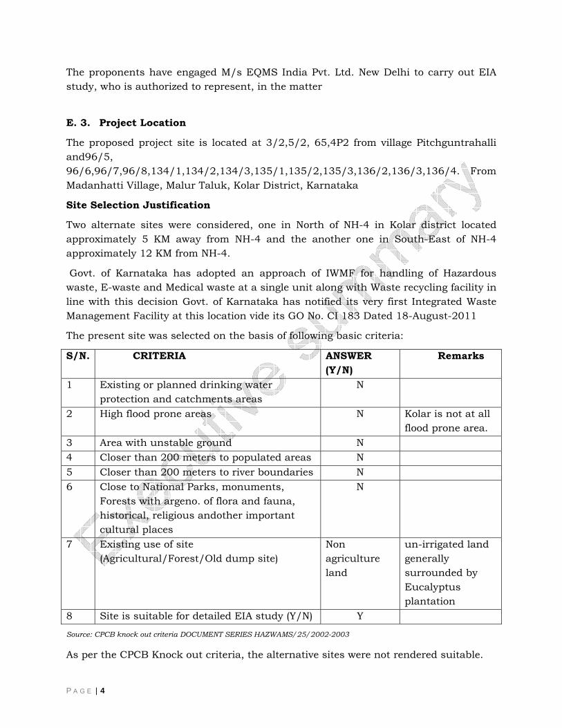
The present site was selected on the basis of following basic criteria:
S/N. CRITERIA ANSWER (Y/N)
Remarks
1 Existing or planned drinking water protection and catchments areas
N
2 High flood prone areas N Kolar is not at all flood prone area.
3 Area with unstable ground N 4 Closer than 200 meters to populated areas N 5 Closer than 200 meters to river boundaries N 6 Close to National Parks, monuments,
Forests with argeno. of flora and fauna, historical, religious andother important cultural places
N
7 Existing use of site (Agricultural/Forest/Old dump site)
Non agriculture land
un-irrigated land generally surrounded by Eucalyptus plantation
8 Site is suitable for detailed EIA study (Y/N) Y Source: CPCB knock out criteria DOCUMENT SERIES HAZWAMS/25/2002-2003
As per the CPCB Knock out criteria, the alternative sites were not rendered suitable.
P A G E | 5
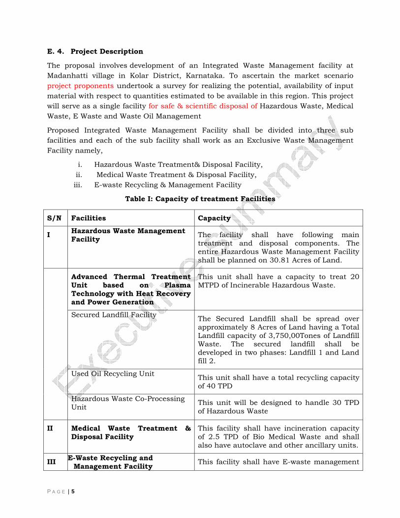
E. 4. Project Description
The proposal involves development of an Integrated Waste Management facility at Madanhatti village in Kolar District, Karnataka. To ascertain the market scenario project proponents undertook a survey for realizing the potential, availability of input material with respect to quantities estimated to be available in this region. This project will serve as a single facility for safe & scientific disposal of Hazardous Waste, Medical Waste, E Waste and Waste Oil Management
Proposed Integrated Waste Management Facility shall be divided into three sub facilities and each of the sub facility shall work as an Exclusive Waste Management Facility namely,
i. Hazardous Waste Treatment& Disposal Facility, ii. Medical Waste Treatment & Disposal Facility, iii. E-waste Recycling & Management Facility
Table I: Capacity of treatment Facilities
S/N Facilities Capacity
I Hazardous Waste Management Facility
The facility shall have following main treatment and disposal components. The entire Hazardous Waste Management Facility shall be planned on 30.81 Acres of Land.
Advanced Thermal Treatment Unit based on Plasma Technology with Heat Recovery and Power Generation
This unit shall have a capacity to treat 20 MTPD of Incinerable Hazardous Waste.
Secured Landfill Facility
The Secured Landfill shall be spread over approximately 8 Acres of Land having a Total Landfill capacity of 3,750,00Tones of Landfill Waste. The secured landfill shall be developed in two phases: Landfill 1 and Land fill 2.
Used Oil Recycling Unit
This unit shall have a total recycling capacity of 40 TPD
Hazardous Waste Co-Processing Unit
This unit will be designed to handle 30 TPD of Hazardous Waste
II Medical Waste Treatment & Disposal Facility
This facility shall have incineration capacity of 2.5 TPD of Bio Medical Waste and shall also have autoclave and other ancillary units.
III E-Waste Recycling and Management Facility This facility shall have E-waste management
P A G E | 6
capacity of 4000 TPA
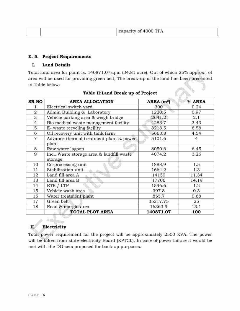
E. 5. Project Requirements
I. Land Details Total land area for plant is. 140871.07sq.m (34.81 acre). Out of which 25% approx.) of area will be used for providing green belt, The break-up of the land has been presented in Table below:
Table II:Land Break up of Project
SR NO AREA ALLOCATION AREA (m²) % AREA 1 Electrical switch yard 300 0.24 2 Admin Building & Laboratory 1220.5 0.97 3 Vehicle parking area & weigh bridge 2641.2 2.1 4 Bio medical waste management facility 4283.7 3.43 5 E- waste recycling facility 8218.5 6.58 6 Oil recovery unit with tank farm 5663.8 4.54 7 Advance thermal treatment plant & power
plant 5101.6 4
8 Raw water lagoon 8050.6 6.45 9 Inci. Waste storage area & landfill waste
storage 4074.2 3.26
10 Co-processing unit 1888.9 1.5 11 Stabilization unit 1664.2 1.3 12 Land fill area A 14150 11.34 13 Land fill area B 17706 14.19 14 ETP / LTP 1596.6 1.2 15 Vehicle wash area 397.8 0.3 16 Water treatment plant 855.7 0.68 17 Green belt 35217.75 25 18 Road & margin area 16363.9 13.1 TOTAL PLOT AREA 140871.07 100
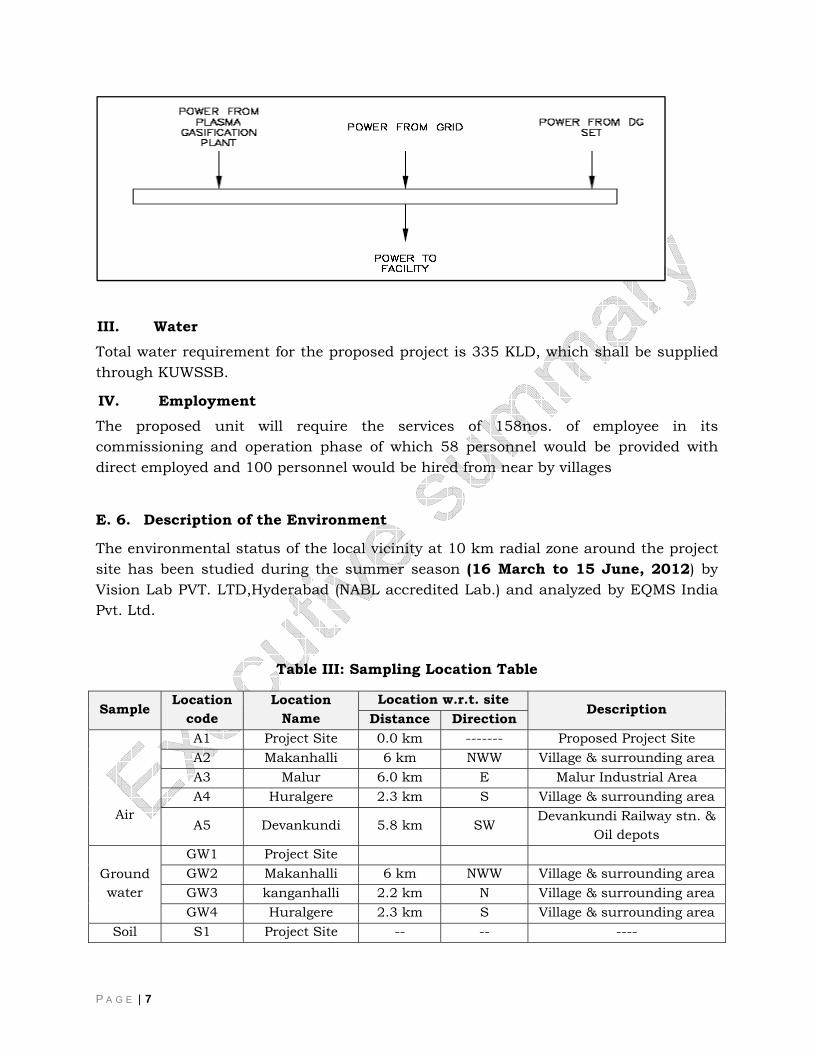
II. Electricity
Total power requirement for the project will be approximately 2500 KVA. The power will be taken from state electricity Board (KPTCL). In case of power failure it would be met with the DG sets proposed for back up purposes.
P A G E | 7
III. Water Total water requirement for the proposed project is 335 KLD, which shall be supplied through KUWSSB.
IV. Employment The proposed unit will require the services of 158nos. of employee in its commissioning and operation phase of which 58 personnel would be provided with direct employed and 100 personnel would be hired from near by villages
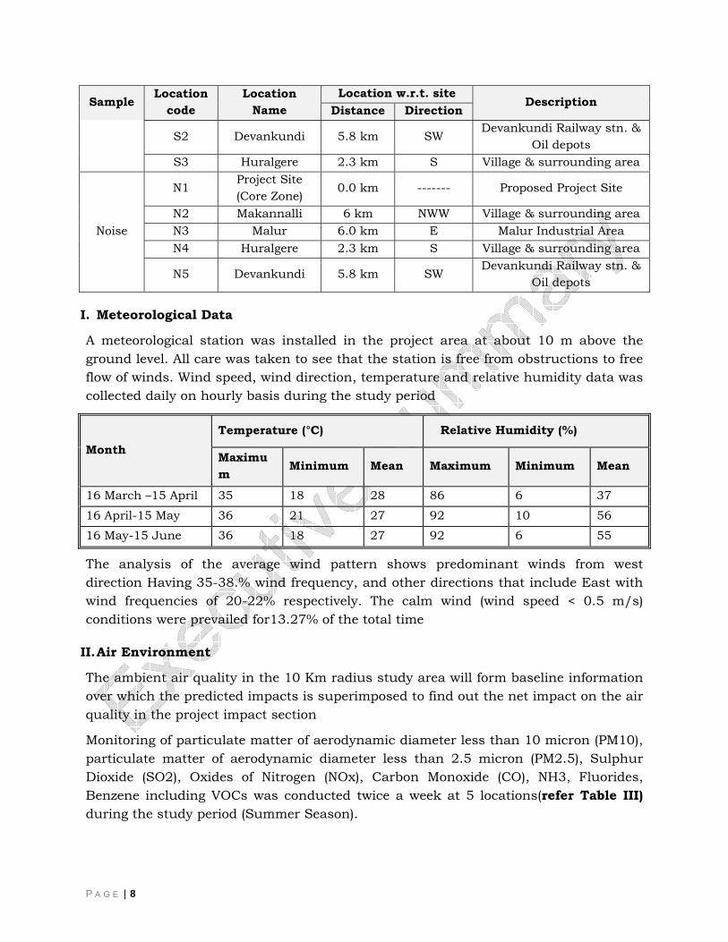
E. 6. Description of the Environment
The environmental status of the local vicinity at 10 km radial zone around the project site has been studied during the summer season (16 March to 15 June, 2012) by Vision Lab PVT. LTD,Hyderabad (NABL accredited Lab.) and analyzed by EQMS India Pvt. Ltd.
Table III: Sampling Location Table
Sample Location
code Location
Name Location w.r.t. site
Description Distance Direction
Air
A1 Project Site 0.0 km ------- Proposed Project Site A2 Makanhalli 6 km NWW Village & surrounding area A3 Malur 6.0 km E Malur Industrial Area A4 Huralgere 2.3 km S Village & surrounding area
A5 Devankundi 5.8 km SW Devankundi Railway stn. & Oil depots
Ground water
GW1 Project Site GW2 Makanhalli 6 km NWW Village & surrounding area GW3 kanganhalli 2.2 km N Village & surrounding area GW4 Huralgere 2.3 km S Village & surrounding area
Soil S1 Project Site -- -- ----
P A G E | 8
Sample Location code
Location Name
Location w.r.t. site Description
Distance Direction
S2 Devankundi 5.8 km SW Devankundi Railway stn. & Oil depots
S3 Huralgere 2.3 km S Village & surrounding area
Noise
N1 Project Site (Core Zone) 0.0 km ------- Proposed Project Site
N2 Makannalli 6 km NWW Village & surrounding area N3 Malur 6.0 km E Malur Industrial Area N4 Huralgere 2.3 km S Village & surrounding area
N5 Devankundi 5.8 km SW Devankundi Railway stn. & Oil depots
I. Meteorological Data
A meteorological station was installed in the project area at about 10 m above the ground level. All care was taken to see that the station is free from obstructions to free flow of winds. Wind speed, wind direction, temperature and relative humidity data was collected daily on hourly basis during the study period
Month Temperature (°C) Relative Humidity (%)
Maximum
Minimum Mean Maximum Minimum Mean
16 March –15 April 35 18 28 86 6 37
16 April-15 May 36 21 27 92 10 56
16 May-15 June 36 18 27 92 6 55
The analysis of the average wind pattern shows predominant winds from west direction Having 35-38.% wind frequency, and other directions that include East with wind frequencies of 20-22% respectively. The calm wind (wind speed < 0.5 m/s) conditions were prevailed for13.27% of the total time
II. Air Environment
The ambient air quality in the 10 Km radius study area will form baseline information over which the predicted impacts is superimposed to find out the net impact on the air quality in the project impact section
Monitoring of particulate matter of aerodynamic diameter less than 10 micron (PM10), particulate matter of aerodynamic diameter less than 2.5 micron (PM2.5), Sulphur Dioxide (SO2), Oxides of Nitrogen (NOx), Carbon Monoxide (CO), NH3, Fluorides, Benzene including VOCs was conducted twice a week at 5 locations(refer Table III) during the study period (Summer Season).
P A G E | 9
After Comparing the analysis Results with the NAAQ standards of MoEF august 2009.It can be concluded that the air quality of the monitored locations in the study area are well within the permissible standards for Industrial, Residential, Rural & other areas.
III. Noise
Noise levels were recorded at four different locations(refer Table III) within the study area. It has been observed that in all the locations, the noise level during day time and night time was well within limit specified for Residential areas i.e. 65dB (in Day),55dB(in night) and industrial limitsi.e.75dB (in Day),70dB(in night).
However, locally the installed machinery’s noise level should be studied after installation of the plant machineries.
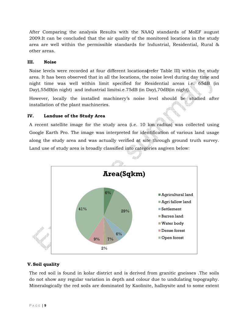
IV. Landuse of the Study Area
A recent satellite image for the study area (i.e. 10 km radius) was collected using
Google Earth Pro. The image was interpreted for identification of various land usage
along the study area and was actually verified at site through ground truth survey.
Land use of study area is broadly classified into categories asgiven below:
V. Soil quality
The red soil is found in kolar district and is derived from granitic gneisses .The soils do not show any regular variation in depth and colour due to undulating topography. Mineralogically the red soils are dominated by Kaolinite, halloysite and to some extent
6%
29%
6%7%
2%
9%
41%
Area(Sqkm)
Agricultural land
Agri fallow land
Settlement
Barren land
Water body
Dense forest
Open forest
P A G E | 10
iron and aluminium oxides. The soil samples were taken fromvarious locations (refer Table I)and examined for various parameters to determine the existing soil characteristics of the study area.
From the analysis it is concluded that Physical Properties of Soil i.e. Sand, silt, clay etc. reveals that soil is sandy clay in nature. The type of soil is best suited for landfills because it is impervious to water, chemicals and it compacts very well.
VI. Topography
The topography of the project site and the study area of 10 km radial zone is calculated with the help of contour and TIN map.
The elevation of the project area varies from 840 to 960 m in general. However, in the northern and western side to the project area the elevations are in the range of 910 to 920 m, which provides a gentle slope towards east direction of the project site.
VII. Ground water Quality
Ground Water samples were collected from four locations (refer Table III) within the study area as following and analyzed for parameter mentioned in IS 10500.The summary of the results is given below
S.N. Name of Village
Parameters Above
Desirable Value Maximum Permissible Value
1. Project site TDS, Total Alkalinity as CaCO3, Magnesium as Mg, Fluorine as F
Total Hardness as CaCO3, calcium as Ca
2. Makanhalli
TDS, Total Alkalinity as CaCO3, Total Hardness as CaCO3, calcium as Ca, Magnesium as Mg
-
3. Kanganhali
TDS, Total Alkalinity as CaCO3, Chlorides as Cl-, Magnesium as Mg, Fluoride as F, Copper as Cu, Arsenic as As
Total Hardness as CaCO3, calcium as Ca
4. Huralgere
TDS, , Total Alkalinity as CaCO3, Sulphates as SO4-2, calcium as Ca, Magnesium as Mg, Fluoride as F, Copper as Cu, Arsenic as As
Total Hardness as CaCO3,
The Ground water quality in the region has been compared with respect to the Drinking Water Quality Standards as per IS: 10500:1991 and it has been found that
P A G E | 11
the Ground water is not desirable for Drinking Purposes. Some of the Parameters like Total Hardness as CaCO3, calcium as Ca which is above Permissible Limit
It is also noticed that arsenic in Kanganhali and Huralgere village is also exceeding the desirable arsenic value for drinking water. The Potential health impacts of arsenic can be Skin damage or problems with circulatory systems, and may have increased risk of getting cancer.
VIII. Surface Water Quality
No Surface Water samples were collected as because of no surface water body was found within the study area.
IX. Biological Environment
For the purpose of surveying the vegetation quadrates were laid to record phyto- sociological features of the vegetation. The vegetation data collected for phytosociological information were analyzed
Project area has been defined as core zone (CZ) and surrounding area has been defined as Buffer Zone (BZ).
Total Nine study sites were selected following general survey No reserve forest was found in the adjoining areas except the village waste land and plantation along the roadside. However, commercial plantation for Eucalyptus has been undertaken at large scale. No perennial water bodies and drains / stream are present in the study area. However, some low lying area where soil has been dugout for Brick Industries are able to get stagnate some rain waters.. It was also observed from the landuse pattern that most of the area falls under agriculture land and drought prone in nature
During the study no endangered species of flora and fauna was observed in the study area and same has also been confirmed from the record of State Forest Department as per Red data book of Botanical Survey of India and Wild Life (Protection) Act 1972.
Ecological Sensitive Areas No major eco-system / biosphere reserves have been identified within the periphery of the project site. Also, the study area does not contain any such features having great historical or archaeological importance.
Fisheries and Aquatic Life No natural or commercial fishery activities are observed within 10 Km radius of the existing premises, and hence proposed project activities are not envisaged to have any adverse effect on fisheries and aquatic life.
National Parks/wildlife Sanctuary/Reserve Forest
P A G E | 12
There are no National Parks/wildlife sanctuaries in the 10 km radius of the study area.
X. Socio-Economic Profile
The study area of 10 km radial zone mainly falls in the Tehsil: Malur of District Kolar and, Tehsil:Haskote of district Bangalore rural.There are total 28 villages in study area, 19 of them belongs to Tehsil: Malur, 9 of them in Hoskote Tehsil.
Education facilities
There are 34 Primary School, 4 Secondary Schools in Study Area. No College exists in the Study Area. Almost all of the villages have at least one primary School.
Health facilities
No Hospitals and Dispensaries are present in the study area There are only 1 Primary Health Centre and 10 Primary Health Sub-centres found in the study Area. However, several private medical practitioner and community health workers are also found.
Drinking Water facilities
Villagers depend on groundwater as a source of Drinking water. Hand pumps, Well water, Tube well and Tap water are observed in almost every village.
Communication Facilities
There are 10 post office found in the study area. 73 Telephone connections were encountered in the study area.
Banking Facilities
2 Banks and 6 Credit Societies are found within the 28 Villages of Study Area.
E. 7. Anticipated Environmental Impact Identification, Prediction and Mitigation
The methodology adopted to carryout impact assessment of the Common Hazardous waste facility is such that the whole Project is divided into major activities and for each activity adverse or positive impact is identified.on the Basis of these the complete chapter is divided into following sections
Identification of major Activities
Impact Prediction, evaluation due to these activities and its mitigation Measures
Impact analysis i.e. consequence/Score analysis
I. Air Environment
P A G E | 13
Construction phase
The sources of air emission during construction phase will include site clearing, vehicles movement, materials storages and handling and operation of construction equipment. Emissions from them are expected to result in temporary degradation of air quality, primarily in the working environment affecting construction employees. However, dust generation and PM rise in the ambient air will be coarse and will settle within a short distance close to the construction sites. Hence, dust and other emissions are unlikely to spread sufficiently to affect the surroundings of the construction site.
Mitigation Measures:
Dust Control
Water spray, through water trucks is an effective way to keep dust under control. Sprinklers can also be employed to deliver continuous moisture in dust prone areas.
High vehicle speeds increase the amount of fugitive dust created from unpaved areas. Reducing the speed of a vehicle to 20 km/hr. can reduce emissions by a large extent.
Care shall be taken to keep all material storages adequately covered and contained so that they are not exposed to situations, where winds on site could lead to dust/ particulate emissions. Fabrics and plastics for covering piles of soils and debris is an effective means to reduce fugitive dust from the material stores/ warehouses.
Spills of dirt or dusty materials shall be cleaned up promptly so that the spilled materials do not become a source of fugitive emission.
Spilled concrete slurries or liquid wastes shall be contained/ cleaned up immediately before they can infiltrate into the soil/ ground or runoff in nearby areas.
Gaseous Emissions Control
Regular maintenance of machinery and equipment will be carried out.
All the vehicles used for construction activity shall be checked for ‘Pollution under Control’.
Ambient air quality monitoring should be carried out during construction phase. If monitored parameters are above the prescribed limits, suitable control measures must be taken
Operation Phase
Impacts on ambient air during operation phase would be due to emissions from the stacks attached to plasma gasification unit, incinerator of medical waste, metal recovery unit and coal fired boilers. All except DG sets are continuous stacks. In
P A G E | 14
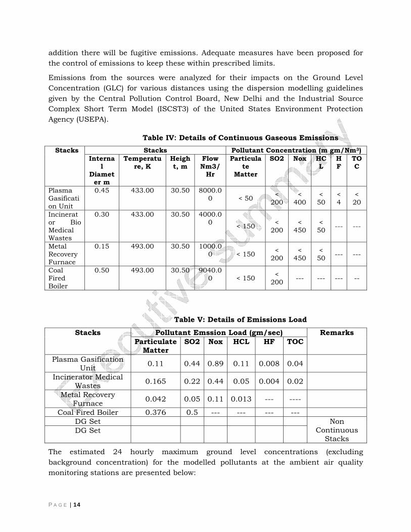
addition there will be fugitive emissions. Adequate measures have been proposed for the control of emissions to keep these within prescribed limits.
Emissions from the sources were analyzed for their impacts on the Ground Level Concentration (GLC) for various distances using the dispersion modelling guidelines given by the Central Pollution Control Board, New Delhi and the Industrial Source Complex Short Term Model (ISCST3) of the United States Environment Protection Agency (USEPA).
Table IV: Details of Continuous Gaseous Emissions Stacks
Stacks Pollutant Concentration (m gm/Nm3) Interna
l Diamet
er m
Temperature, K
Height, m
Flow Nm3/
Hr
Particulate
Matter
SO2
Nox
HCL
HF
TOC
Plasma Gasification Unit
0.45 433.00 30.50 8000.00 < 50 <
200 <
400 < 50
< 4
< 20
Incinerator Bio Medical Wastes
0.30 433.00 30.50 4000.00 < 150 <
200 <
450 < 50 --- ---
Metal Recovery Furnace
0.15 493.00 30.50 1000.00 < 150 <
200 <
450 < 50 --- ---
Coal Fired Boiler
0.50 493.00 30.50 9040.00 < 150 <
200 --- --- --- --
Table V: Details of Emissions Load
Stacks Pollutant Emssion Load (gm/sec) Remarks Particulate
Matter SO2
Nox
HCL
HF TOC
Plasma Gasification Unit 0.11 0.44 0.89 0.11 0.008 0.04
Incinerator Medical Wastes 0.165 0.22 0.44 0.05 0.004 0.02
Metal Recovery Furnace 0.042 0.05 0.11 0.013 --- ----
Coal Fired Boiler 0.376 0.5 --- --- --- --- DG Set Non
Continuous Stacks
DG Set
The estimated 24 hourly maximum ground level concentrations (excluding background concentration) for the modelled pollutants at the ambient air quality monitoring stations are presented below:
P A G E | 15
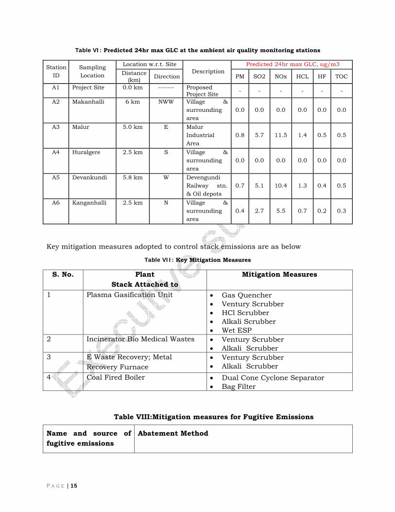
Table VI: Predicted 24hr max GLC at the ambient air quality monitoring stations
Station ID
Sampling Location
Location w.r.t. Site Description
Predicted 24hr max GLC, ug/m3 Distance
(km) Direction PM SO2 NOx HCL HF TOC
A1 Project Site 0.0 km ------- Proposed Project Site - - - - - -
A2 Makanhalli 6 km NWW Village & surrounding area
0.0 0.0 0.0 0.0 0.0 0.0
A3 Malur 5.0 km E Malur Industrial Area
0.8 5.7 11.5 1.4 0.5 0.5
A4 Huralgere 2.5 km S Village & surrounding area
0.0 0.0 0.0 0.0 0.0 0.0
A5 Devankundi 5.8 km W Devengundi Railway stn. & Oil depots
0.7 5.1 10.4 1.3 0.4 0.5
A6 Kanganhalli 2.5 km N Village & surrounding area
0.4 2.7 5.5 0.7 0.2 0.3
Key mitigation measures adopted to control stack emissions are as below
Table VII: Key Mitigation Measures
S. No. Plant Stack Attached to
Mitigation Measures
1 Plasma Gasification Unit • Gas Quencher • Ventury Scrubber • HCl Scrubber • Alkali Scrubber • Wet ESP
2 Incinerator Bio Medical Wastes • Ventury Scrubber • Alkali Scrubber
3 E Waste Recovery; Metal Recovery Furnace
• Ventury Scrubber • Alkali Scrubber
4 Coal Fired Boiler • Dual Cone Cyclone Separator • Bag Filter
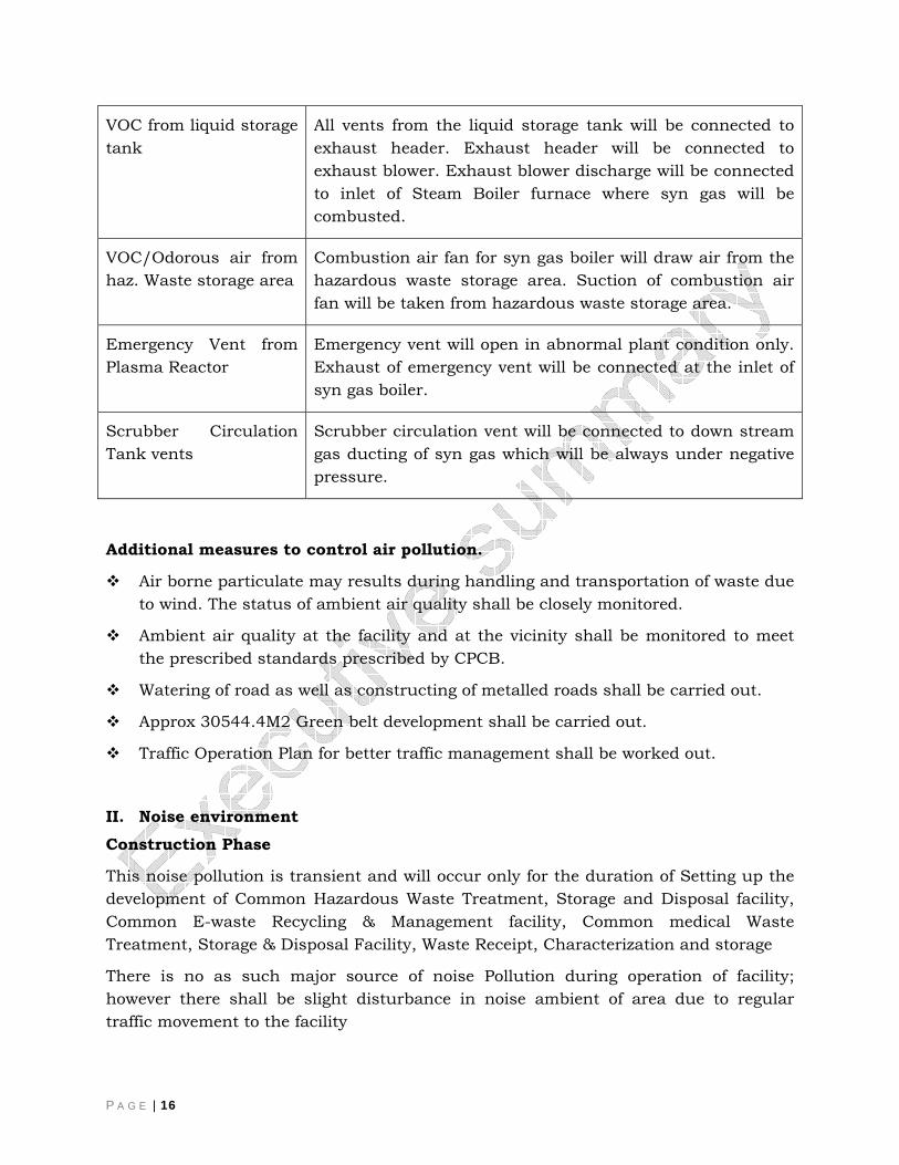
Table VIII:Mitigation measures for Fugitive Emissions
Name and source of fugitive emissions
Abatement Method
P A G E | 16
VOC from liquid storage tank
All vents from the liquid storage tank will be connected to exhaust header. Exhaust header will be connected to exhaust blower. Exhaust blower discharge will be connected to inlet of Steam Boiler furnace where syn gas will be combusted.
VOC/Odorous air from haz. Waste storage area
Combustion air fan for syn gas boiler will draw air from the hazardous waste storage area. Suction of combustion air fan will be taken from hazardous waste storage area.
Emergency Vent from Plasma Reactor
Emergency vent will open in abnormal plant condition only. Exhaust of emergency vent will be connected at the inlet of syn gas boiler.
Scrubber Circulation Tank vents
Scrubber circulation vent will be connected to down stream gas ducting of syn gas which will be always under negative pressure.
Additional measures to control air pollution.
Air borne particulate may results during handling and transportation of waste due to wind. The status of ambient air quality shall be closely monitored.
Ambient air quality at the facility and at the vicinity shall be monitored to meet the prescribed standards prescribed by CPCB.
Watering of road as well as constructing of metalled roads shall be carried out.
Approx 30544.4M2 Green belt development shall be carried out.
Traffic Operation Plan for better traffic management shall be worked out.
II. Noise environment Construction Phase
This noise pollution is transient and will occur only for the duration of Setting up the development of Common Hazardous Waste Treatment, Storage and Disposal facility, Common E-waste Recycling & Management facility, Common medical Waste Treatment, Storage & Disposal Facility, Waste Receipt, Characterization and storage
There is no as such major source of noise Pollution during operation of facility; however there shall be slight disturbance in noise ambient of area due to regular traffic movement to the facility
P A G E | 17
Mitigation measures for noise will include the following:
Sufficient engineering control during installation of equipments and machineries (like mufflers in DG sets) is to be ensured to reduce noise levels at source.
Proper and timely maintenance of machineries and preventive maintenance of vehicles is to be adopted to reduce noise levels.
Plant and equipment will be designed to ensure that noise generated is limited to CPCB norms. Equipment will be provided with noise control measures such as acoustic insulation etc, to ensure noise abatement. Rotating equipment will be properly balanced. Where high noise levels are produced, employees will be provided with ear protection devices.
Personnel Protective Equipments (PPE) like ear plugs/muffs is to be given to all the workers at site and it will be ensured that the same are wore by everybody during their shift.
All the openings like covers, partitions shall be acoustically sealed.
III. Water Environment Impact by integrated waste Management Facility on Water environment can be predicted in two ways i.e.
Impact on water resources
Impact on Water Quality
Impact on water resources
Surface water resources
No impact on surface water resources is anticipated during both the construction phase and operational phase of the project as there is no such surfacewater resources prevails in the study area,
Ground Water Resources
No impact on Ground water resources is anticipated during both construction as well as operational phase of the project as there is no withdrawl of water, however Water demand shall be met through state Water Board supply.
Impact on Water Quality
Construction Phase
The wastewater generated during construction phase is mainly from construction works & domestic activities. Adequate drainage system will be provided for runoff water to avoid water logging and it will be utilized during the construction phase for

P A G E | 18
the proposed plant. Therefore, no long term adverse impact on water quality (surface as well as ground) is anticipated during construction phase
Operation Phase
The total maximum requirement of water for the facility is delineated to 335 KLD maximum.
Two alternate mode of disposal is proposed for the facility.
Alternative I: Disposal of treated waste water to CETP through tankers
Alternative II: Disposal of treated waste water through Multi EffectEvaporation system (MEES) and recycle treated waste water to plant for reuse. Waste water treatment system consist of following sub systems
Physico Chemical Treatment Units
Heavy Metal Removal Units
Oil Removal System
Multi Effect Evaporation system
Packaged Sewage Treatment Plant
The following mitigation measures will also be implemented:
EWML will use best engineering technique during setting up the development of Common Hazardous Waste Treatment facility so that proposed activities will not contaminate the ground water.
Hazardous waste storage area and plant area will be completely covered from top and side. Strom water run off will be managed through separate storm water drains. Before discharging storm water into surface drain, it will be passed through small RCC pit where online pH sensor and recorder will be provided to keep check on pH of outgoing storm water.
Regular monitoring of ground water quality through monitoring wells as per CPCB guideline.
The water samples shall be analyzed for the 36 physical, chemical and bacteriological parameters as per MOEF guidelines.
The landfill is proposed with double liner system with a view to avoid the leachate infiltration into the ground
Vehicle or Wheel Wash shall be treated in Physico Chemical Treatment Plant followed by MEE for reuse or sent to CETP for further disposal.
ETP sludge shall be disposed off to secure landfill
IV. Land Environment
P A G E | 19
As the project site is on non agriculture land (Provided in ch-2 i.e. 30.81 Acre) and no major rehabilitation prevails in the site area so impact on land use shall be of no significance.
However Positive Impact will be there as Project Proponent will provide the Employment to the Workers from nearby villages (158 workers) which further affect (Positive effect) the Occupational structure of the Area.
V. Impact on Soil and Geology During the operational phase, there is a probability of accidental spillage of hazardous waste on the routes through which hazardous waste would be transported and its adjoining areas if a vehicle carrying hazardous waste meets with an accident. Since the hazardous waste is stored at the site for incineration there is a possibility that due to accidental spillage soil can be contaminated. Land fills gas production and migration leading to changes in soil temperature.
Mitigation Measures
During the operational phase of hazardous landfill as there is a possibility of contamination risk due to damage of liners of the landfill at the site. Therefore the Landfill will be constructed by complying the CPCB Land Fill sitting Guide lines. Store, preserve and protect topsoil separately to use it during restoration period; and domestic waste
VI. Ecology and Biodiversity There is no notified/protected ecologically sensitive area including national park, sanctuary, Elephant/Tiger reserves existing in the study area. Most of the vegetation is aggregated on agricultural boundaries, road side plantation, private land and social forest area
Mitigation Measures
Installation of systems to discourage nesting or perching of birds indangerous environments
VII. Socio Economic Critical analysis of the socio-economic profile of the area vis-à-vis its scenario with project activities identifies the following impacts:
Social impacts like property price depreciation represent an external ‘cost’ of waste disposal and treatment facilities. Property values are also affected by their proximity to a new landfill. The other adverse impact includes stress arising from fear to risk to health, etc. However, as a result of such projects, there would be employment generation, business generation, infrastructure development, etc.
P A G E | 20
The proposed activities shall generate indirect employment in the region due to the requirement of workers in trail making, supply of raw material, auxiliary and ancillary works, which would marginally improve the economic status of the people.
The activities would result in an increase in local skill levels through exposure to activities.
As the existing loose / soft surface roads, trails shall be upgraded to facilitate the movement of the heavy equipment required, the project in turn would lead to improvement in transport facilities.
Mitigation Measures
Proper compensation for land and crop based on APMC rates: this does not have significance in this case as the land was specifically allotted to the project proponent for the TSDF project by State Government.
Approach roads will be upgraded to facilitate heavy vehicular movement
Project proponent may provide educational aid to local villages based on need and request from the village Panchayat.
Conclusion
After implementation of all the mitigation measures the project can be considered as non –polluting project on the basis of rating criteria discussed in detail in EIA report.
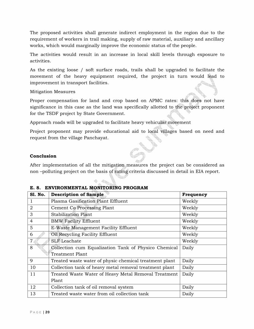
E. 8. ENVIRONMENTAL MONITORING PROGRAM Sl. No. Description of Sample Frequency 1 Plasma Gasification Plant Effluent Weekly 2 Cement Co Processing Plant Weekly 3 Stabilization Plant Weekly 4 BMW Facility Effluent Weekly 5 E-Waste Management Facility Effluent Weekly 6 Oil Recycling Facility Effluent Weekly 7 SLF Leachate Weekly 8 Collection cum Equalization Tank of Physico Chemical
Treatment Plant Daily
9 Treated waste water of physic chemical treatment plant Daily 10 Collection tank of heavy metal removal treatment plant Daily 11 Treated Waste Water of Heavy Metal Removal Treatment
Plant Daily
12 Collection tank of oil removal system Daily 13 Treated waste water from oil collection tank Daily
P A G E | 21
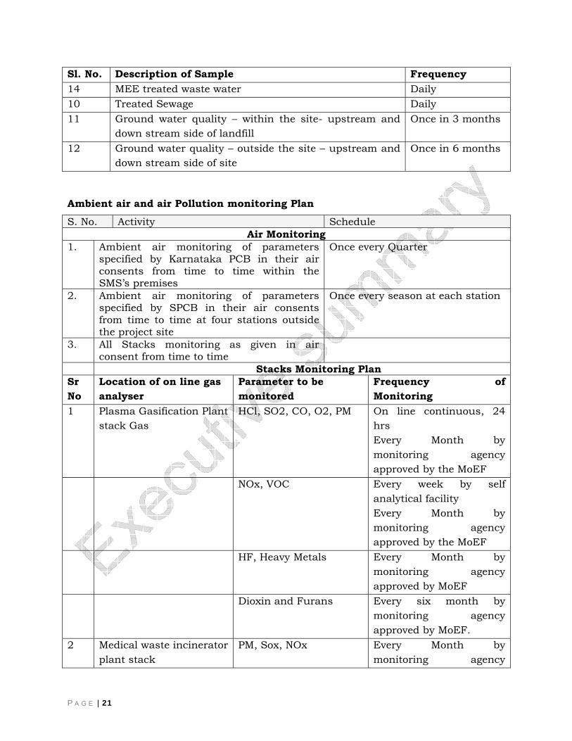
Sl. No. Description of Sample Frequency 14 MEE treated waste water Daily 10 Treated Sewage Daily 11 Ground water quality – within the site- upstream and
down stream side of landfill Once in 3 months
12 Ground water quality – outside the site – upstream and down stream side of site
Once in 6 months
Ambient air and air Pollution monitoring Plan
S. No. Activity Schedule Air Monitoring
1. Ambient air monitoring of parameters specified by Karnataka PCB in their air consents from time to time within the SMS’s premises
Once every Quarter
2. Ambient air monitoring of parameters specified by SPCB in their air consents from time to time at four stations outside the project site
Once every season at each station
3. All Stacks monitoring as given in air consent from time to time
Stacks Monitoring Plan Sr No
Location of on line gas analyser
Parameter to be monitored
Frequency of Monitoring
1 Plasma Gasification Plant stack Gas
HCl, SO2, CO, O2, PM On line continuous, 24 hrs Every Month by monitoring agency approved by the MoEF
NOx, VOC Every week by self analytical facility Every Month by monitoring agency approved by the MoEF
HF, Heavy Metals Every Month by monitoring agency approved by MoEF
Dioxin and Furans Every six month by monitoring agency approved by MoEF.
2 Medical waste incinerator plant stack
PM, Sox, NOx Every Month by monitoring agency
P A G E | 22
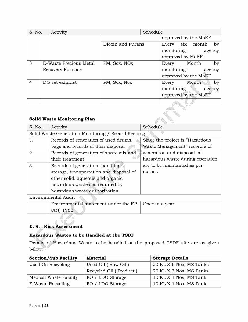
S. No. Activity Schedule approved by the MoEF
Dioxin and Furans Every six month by monitoring agency approved by MoEF.
3
E-Waste Precious Metal Recovery Furnace
PM, Sox, NOx Every Month by monitoring agency approved by the MoEF
4 DG set exhaust PM, Sox, Nox Every Month by monitoring agency approved by the MoEF
Solid Waste Monitoring Plan
S. No. Activity Schedule Solid Waste Generation Monitoring / Record Keeping 1. Records of generation of used drums,
bags and records of their disposal Since the project is “Hazardous Waste Management” record s of generation and disposal of hazardous waste during operation are to be maintained as per norms.
2. Records of generation of waste oils and their treatment
3. Records of generation, handling, storage, transportation and disposal of other solid, aqueous and organic hazardous wastes as required by hazardous waste authorization
Environmental Audit Environmental statement under the EP
(Act) 1986 Once in a year
E. 9. Risk Assessment
Hazardous Wastes to be Handled at the TSDF Details of Hazardous Waste to be handled at the proposed TSDF site are as given below:
Section/Sub Facility Material Storage Details Used Oil Recycling Used Oil ( Raw Oil ) 20 KL X 6 Nos, MS Tanks
Recycled Oil ( Product ) 20 KL X 3 Nos, MS Tanks Medical Waste Facility FO / LDO Storage 10 KL X 1 Nos, MS Tank E-Waste Recycling FO / LDO Storage 10 KL X 1 Nos, MS Tank
P A G E | 23
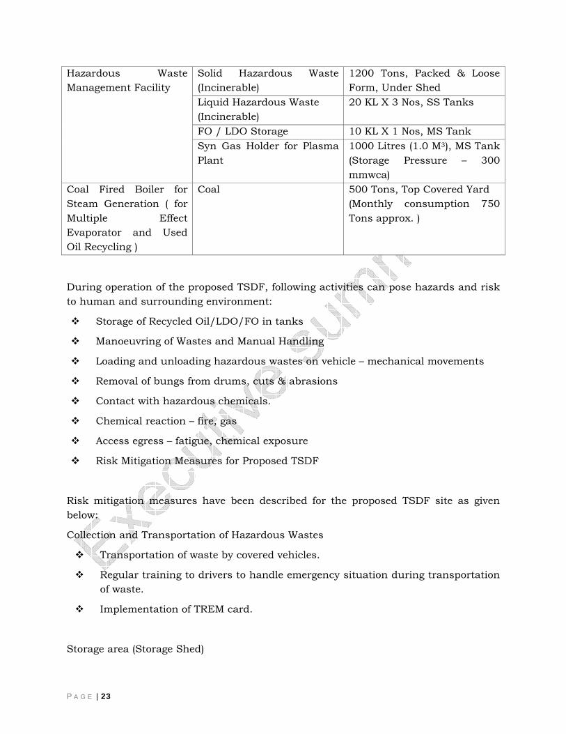
Hazardous Waste Management Facility
Solid Hazardous Waste (Incinerable)
1200 Tons, Packed & Loose Form, Under Shed
Liquid Hazardous Waste (Incinerable)
20 KL X 3 Nos, SS Tanks
FO / LDO Storage 10 KL X 1 Nos, MS Tank Syn Gas Holder for Plasma Plant
1000 Litres (1.0 M3), MS Tank (Storage Pressure – 300 mmwca)
Coal Fired Boiler for Steam Generation ( for Multiple Effect Evaporator and Used Oil Recycling )
Coal 500 Tons, Top Covered Yard (Monthly consumption 750 Tons approx. )
During operation of the proposed TSDF, following activities can pose hazards and risk to human and surrounding environment:
Storage of Recycled Oil/LDO/FO in tanks
Manoeuvring of Wastes and Manual Handling
Loading and unloading hazardous wastes on vehicle – mechanical movements
Removal of bungs from drums, cuts & abrasions
Contact with hazardous chemicals.
Chemical reaction – fire, gas
Access egress – fatigue, chemical exposure
Risk Mitigation Measures for Proposed TSDF
Risk mitigation measures have been described for the proposed TSDF site as given below:
Collection and Transportation of Hazardous Wastes
Transportation of waste by covered vehicles.
Regular training to drivers to handle emergency situation during transportation of waste.
Implementation of TREM card.
Storage area (Storage Shed)
P A G E | 24
Flammable, ignitable, reactive and non-compatible wastes should be stored separately and never should be stored in the same storage shed.
Storage area may consist of different sheds for storing different kinds of incinerable hazardous wastes and sheds should be provided with suitable openings.
Adequate storage capacity (i.e. 50 % of the annual capacity of the hazardous waste incinerator) should be provided in the TSDF premises.
Storage area should be designed to withstand the load of waste stocked and any damage from the hazardous waste spillage.
Hazardous waste storage area should be provided with the flameproof electrical fittings and it should be strictly adhered to.
Automatic smoke, heat detection system should be provided in the sheds. Adequate fire fighting systems should be provided for the storage area and boundary of TSDF.
There should be at least 15 meter distance between the storage sheds.
Loading and unloading of wastes in storage sheds should only be done under the supervision of the well trained and experienced staff.
“Fire break” of at least 04 meter between two blocks of stacked drums should be provided in the storage shed. One block of drum should not exceed 300 MT of waste.
Minimum of 1.5/>2.5 meter clear space should be left between two adjacent rows of pallets in pair for movement of personnel and or fork lift and inspection.
The storage and handling should have at least two openings/ routes to escape in the event of any fire in the area.
Doors and approaches of the storage area should be of suitable sizes for entry of fork lift and fire fighting equipment;
The exhaust of the vehicles used for the purpose of handling, lifting and transportation within the facility such as forklifts or trucks should be fitted with the approved type of spark arrester.
In order to have appropriate measures to prevent percolation of spills, leaks etc. to the soil and ground water, the storage area should be provided with concrete floor or steel sheet depending on the characteristics of waste handled and the floor must be structurally sound and chemically compatible with wastes.
P A G E | 25
Measures should be taken to prevent entry of runoff into the storage area. The Storage area shall be designed in such a way that the floor level is at least 150 mm above the maximum flood level.
The storage area floor should be provided with secondary containment such as proper slopes as well as collection pit so as to collect wash water and the leakages/spills etc.
All the storage yards should be provided with proper peripheral drainage system connected with the sump so as to collect any accidental spills in roads or within the storage yards as well as accidental flow due to fire fighting.
Special care should be taken for storing medical wastes. It should be kept totally isolated from other wastes:
o All care should be taken sothat infectious material should not leak and infection spread.
o All personnel these wastes should take all care while handling these wastes.
o Medical wastes should be immediately treated and made harmless.
Storage Drums/Containers
The container shall be made or lined with the suitable material, which will not react with, or in other words compatible with the hazardous wastes proposed to be stored.
The stacking of drums in the storage area should be restricted to three high on pallets (wooden frames). Necessary precautionary measures should be taken so as to avoid stack collapse. However, for waste having flash point less than 65.5 oC, the drums should not be stacked more than one height.
No drums should be opened in the storage sheds for sampling etc. and such activity should be done in designated places out side the storage areas;
Drums containing wastes stored in the storage area should be labeled properly indicating mainly type, quantity, characteristics, source and date of storing etc.
Spillage/Leakage Control Measures
The storage areas should be inspected daily for detecting any signs of leaks or deterioration if any. Leaking or deteriorated containers should be removed and ensured that such contents are transferred to a sound container.
P A G E | 26
In case of spills / leaks/dry adsorbents/cotton should be used for cleaning instead of water.
Proper slope with collection pits be provided in the storage area so as to collect the spills/leakages.
Storage areas should be provided with adequate number of spill kits at suitable locations. The spill kits should be provided with compatible sorbent material in adequate quantity.
Fire Protection System
The fire protection system shall comprise of:
Pressurized Hydrant System - For waste storage, PGVR plant, administration building area and other areas also;
Transformer rooms, consumer 11KV SSU, generator set room and UPS room will be outfitted with CO2 total flooding system;
Plasma torch power supply rooms, MCC/PCC room and PLC/Control Room will be outfitted with FM200 Total Flooding System;
Fire detection and alarm system for waste storage area, PGVR plant, power plant block and administration building area;
Fire Fighting system shall comprises of following major equipment and systems;
Electric driven main fire pumps with emergency power from standby Diesel Genset for hydrant network serving of hydrants and hose reels;
All necessary pump controls complete with all accessories for the above-mentioned pumps;
All buried piping and over-ground pipes, fitting, valves, automatic actuators, supports etc for fire water distribution networks;
All necessary sign-posting for the water-hydrant ring system including brackets, complete with accessories;
All electrical rooms will be provided with clean agent automatic fire extinguisher systems
Complete Addressable analogue fire detection system with heat and smoke detectors for various plant area including storages with necessary cabling, interface panels, controllers, sounders, manual call points, sirens, response indicators, and all necessary hardware and accessories; and
P A G E | 27
All necessary electrical equipment, such as LV switch-gear, LV motors, LV power and control cables, control panels with alarm, PBB and interlocks, necessary DC systems, push button stations, cable trays and accessories, cabling, glands lugs, earthing and lightning protection conforming to relevant electrical specifications.
Miscellaneous risk Mitigation Measures
Smoking shall be prohibited in and around the storage areas;
Good house keeping need to be maintained around the storage areas.
Signboards showing precautionary measures to be taken, in case of normal and emergency situations should be displayed at appropriate locations.
To the extent possible, manual operations within storage area are to be avoided. In case of manual operation, proper precautions need to be taken, particularly during loading / unloading of liquid hazardous waste in drums.
A system for inspection of storage area to check the conditions of the containers, spillages, leakages etc. should be established and proper records should be maintained.
The wastes containing volatile solvents or other low vapour pressure chemicals should be adequately protected from direct exposure to sunlight and adequate ventilation should be provided.
Tanks for storage of liquids waste should be properly dyked and should be provided with adequate transfer systems.
Storage sites should have adequate & prompt emergency response equipment systems for the hazardous waste stored on-site. This should include fire fighting arrangement based on the risk assessment, spill management, evacuation and first aid.
Immediately on receipt of the hazardous waste, it should be analyzed and depending upon its characteristics and storage & disposal should be finalized.
Only persons authorized to enter and trained in hazardous waste handling procedures should have access to the hazardous waste storage areas.
Mock drill for onsite emergency should be conducted regularly and records maintained.
Hazard Analysis and Safety Audit
P A G E | 28
During operation of TSDF, a preliminary hazard analysis should be conducted. Safety Audit should be conducted internally by the operator every year & externally once in two years by a reputed expert agency and same should be submitted to the regulatory agencies. Conditions stipulated by SPCBs while granting authorization under Hazardous Waste (Management, Handling & Transboundary Movement) Rules, 2008 to the TSDF operation should be complied.
E. 10. ENVIRONMENTAL MANAGEMENT PLAN
As per TOR Compliances with Respect to Provisions of Bio-Medical Wastes (Management, Handling) Rules, 2000 ,Hazardous Wastes (Management, Handling and Trans-boundary movement) Rules and E- Waste (Management & Handling) Rules, 2011 shall be done according to the action plan provided in the EIA report separately. Some of the vital technological measures shall be undertaken are:
I. Technological Measures Odor Control
The main sources of odour are from waste storage yard, collection sump, sorting area incineration unit and Land fill
Storage Facility
The proposed facility will receive and store the waste in an enclosed area with a negative pressure with the airflow being routed through the incinerator which prevents unpleasant odours from escaping into the atmosphere. While handling odourous wastes, care shall be taken to avoid smell nuisance.
Incineration
Incineration (medical in this case) is the oxidation of the odour into carbon dioxide and water by the combustion of the odour with fuel and air. The reaction takes place at temperatures ranging from 7500C to 8500C.This is generally above the auto-ignition temperature of most solvents and other VOCs and is a reflection of the heat required to maintain the reaction at dilute concentrations with additional process heat losses. In this regime, the destruction efficiency is almost 100%, assuming adequate oxygen supply. In some cases, other compounds may be formed depending on the mixture of fuel and air used the flame temperature and the composition of the odour. These compounds may include carbon monoxide, oxides of nitrogen and sulphur oxides.
Wet scrubbing/Absorption
Wet scrubbing of gases to remove odour involve either absorption in a suitable solvent or chemical treatment with a suitable reagent. It is important that hot, moist streams are cooled before they contact scrubbing solutions. If this is not done the scrubbing
P A G E | 29
solution will be heated and become less efficient and the scrubbing medium will become diluted from condensation of water vapour. Venture scrubbers and packed bed scrubbers are used for this purpose along with absorption of other flue gases like CO, NOx, and SO2 etc.
Landfill Cell
For landfill cell following methods can be used to control odour:
Excluding Development Close to the Site
Green belt development to form a surface capable of sorbing and forming sinks for odorous gases. Leaves with their vast area in a tree crown, sorbs pollutants on their surface, thus effectively reduce their concentrations in the ambient air and source emissions
Ensuring that the operation is carried out under the best management practices
Cleaning and removing spilled debris from storage and transport containers
Minimization of the area and time that the active portion of the landfill remains exposed to the environment
Herbal spray on hazardous waste after disposing it in the landfill cell.
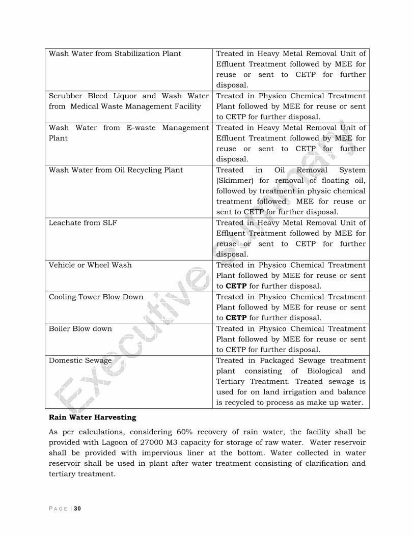
Water and Waste water Management Various waste water bleed streams generated from various section of the plant with typical quality of waste water streams and their treatment method provided in the facility.
Name and source of bleed stream Abatement Method Scrubber Bleed Liquor and Wash Water from Plasma Gasification Plant
Treated in Physico Chemical Treatment Plant followed by MEE for reuse or sent to CETP for further disposal.
Wash Water from “Waste Bank and unit for Co-processing of Hazardous Waste Unit”
Treated in Heavy Metal Removal Unit of Effluent Treatment followed by MEE for reuse or sent to CETP for further disposal.
P A G E | 30
Wash Water from Stabilization Plant Treated in Heavy Metal Removal Unit of Effluent Treatment followed by MEE for reuse or sent to CETP for further disposal.
Scrubber Bleed Liquor and Wash Water from Medical Waste Management Facility
Treated in Physico Chemical Treatment Plant followed by MEE for reuse or sent to CETP for further disposal.
Wash Water from E-waste Management Plant
Treated in Heavy Metal Removal Unit of Effluent Treatment followed by MEE for reuse or sent to CETP for further disposal.
Wash Water from Oil Recycling Plant Treated in Oil Removal System (Skimmer) for removal of floating oil, followed by treatment in physic chemical treatment followed MEE for reuse or sent to CETP for further disposal.
Leachate from SLF Treated in Heavy Metal Removal Unit of Effluent Treatment followed by MEE for reuse or sent to CETP for further disposal.
Vehicle or Wheel Wash Treated in Physico Chemical Treatment Plant followed by MEE for reuse or sent to CETP for further disposal.
Cooling Tower Blow Down Treated in Physico Chemical Treatment Plant followed by MEE for reuse or sent to CETP for further disposal.
Boiler Blow down Treated in Physico Chemical Treatment Plant followed by MEE for reuse or sent to CETP for further disposal.
Domestic Sewage Treated in Packaged Sewage treatment plant consisting of Biological and Tertiary Treatment. Treated sewage is used for on land irrigation and balance is recycled to process as make up water.
Rain Water Harvesting
As per calculations, considering 60% recovery of rain water, the facility shall be provided with Lagoon of 27000 M3 capacity for storage of raw water. Water reservoir shall be provided with impervious liner at the bottom. Water collected in water reservoir shall be used in plant after water treatment consisting of clarification and tertiary treatment.

P A G E | 31
Land Environment
Green Belt Development Approx 25% of total area of plant shall be considered for Green belt area. Green belt is proposed primarily for effective control of pollution. The proposed green belt around the proposed site may be designed taking into consideration the availability of space as the efficiency of green belt in mitigating environmental impact mainly depends on the width of green belt, distance from source and tree height.
The following criterion is to be considered while selecting the species for plantation:
• The plant species should be fast growing. • They should have thick canopy cover. • They should be perennial and evergreen. • They should have high sink potential. • They should be effective in absorbing pollutants without significantly
affecting their growth.
Based on above following plant species are recommended for plantation:
• Acacia nilotica (Babul) • Deldergia sissoo (Shishum) • Acacia auriculiformis (Australian Babul) • Azadirachta indica (Neem) • Lagerstroemia speciosa (Jamun) • Pongamia pinnata (Karanji)
Minimum two rows of plants are required for plantation on roadside to minimize the pollution effects. While planting care should be taken to ensure that plants in second row fall in between the two plants of the first row.
Transportation Management Plan
The transport of waste to a facility provides for the most obvious source of Impact. The physical impact of transport relates not only to volume increases upon existing networks, but also to its operational characteristics and composition, most particularly the percentage of heavy good vehicles. There are various components of the sources of traffic, which will have impact on environmental. These include the location and spatial extent of traffic movements, the operational hours of the facility, the types of wastes being moved, and the volume of traffic being generated. Some of the precautionary steps shall be followed to curtail the pollution due to transportation activities:
The words “HAZARDOUS WASTE” shall be displayed on all sides of the vehicle in Vernacular, Hindi and English.
P A G E | 32
Vehicle used for transportation shall be in accordance with the provisions under the Motor Vehicle Act, 1988, and rules made thereunder.
Transporter shall possess requisite copies of the certificate (valid authorization obtained from the concerned SPCB/PCC for transportation of waste by the waste generator and operator of a facility) for transportation of hazardous waste.
Transporter should have valid “Pollution under Control Certificate” (PUCC) during the transportation of hazardous waste and shall be properly displayed.
Vehicle shall be painted preferably in blue colour with white strip of 15 to 30 cm width running centrally all over the body. This is to facilitate easy identification.
Vehicle should be fitted with mechanical handling equipment as may be required for safe handling and transportation of the wastes.
Emergency phone numbers and TREM Card in Form 11 of HW (M, H & TM) Rules,2008.
Carrying of passengers is strictly prohibited and those associated with the waste haulers shall be permitted only in the cabin.
Transporter shall carry documents of manifest for the wastes during transportation as required under Rule 21 of the HW (M, H & TBM) Rules.
Each vehicle shall carry first-aid kit, spill control equipment and fire extinguisher.
Hazardous Waste transport vehicle shall run only at a speed specified under Motor Vehicle Act in order to avoid any eventuality during the transportation of hazardous waste.
Driver (s) shall be properly trained for handling the emergency situations and safety aspects involved in the transportation of hazardous wastes.
The design of the trucks shall be such that there is no spillage during transportation.
Human resources In case of an emergency, the On-site Emergency Plan of the proposed TSDF will come into action. Effective on-site emergency plan requires that in the event of an accident, nominated functionaries be given specific responsibilities, often separate from their day-to-day activities
The emergency organization follows the usual pattern of the hierarchy. The senior-most functionary available during an emergency at the proposed TSDF takes charge as Chief Emergency Coordinator (CEC) and will locate himself at the designated Primary Command Post. The senior most functionaries for each emergency service will act as coordinator and shall report at the Primary Command Post unless otherwise instructed by the Chief Coordinator.
P A G E | 33
The senior most persons in the shift will be designated as the Site Incident Controller (SIC). The SIC will take charge of the incident site and take the overall command. He will be supported by other key persons representing various emergency services. Key persons are personnel available at the site on round the clock basis. It is to be appreciated that the key persons remain the front line fighters. The role of various coordinators is to assess the situation from time to time, take appropriate decisions in consultation with the CEC and to provide timely resources to the key persons to fight the emergency.
Financial Planning The total project capital outlay for integrated waste management facility is estimated at Rs. 221.69 crores. Also company shall invest 0.1 % to 0.2 % of annual turnover to CSR activities. M2
Proposed Corporate Social Responsibility Charity we believe begins at home and hence our CSR is directed at people in proximity to our work sites, which is why:
We employ local work force around the project site, provide education, health care & capacity building training to the work force. We also show concern and regard towards our project’s local region.
Providing medical facilities to villages in the vicinity of our project sites.
Enhancing the green cover by tree plantation drives.
Organizing water and energy conservation rallies through “SAVE WE”.
In the interest of the society and the nation at large, we support the projects titled:
Child Adoption for Education (CAFÉ)
Child Adoption for Rehabilitation & Education (CARE)
Scholarships for employee’s children for education.
We contribute to the society and environment by safe disposal of hazardous waste.
For CSR budgetary outlay considered tobe 0.1 % to 0.2 % of annual turnover of the company
E. 11. Project Benefits
Having an integrated facility would minimize the risk involved in waste transportation and waste movement and monitoring of such facility would be better and feasible. These factors as well as a strong desire to come up as a single window solution
P A G E | 34
provider for waste management issues; led SMSIL to embark setting up this Integrated Waste Management project, apart from achieving other social objectives.
This project will serve as a single facility for Hazardous Waste, Biomedical Waste, E Waste and Waste Oil Management. It will have various facilities such as Common Hazardous Waste Treatment Storage and Disposal Facility, Common E Waste Management Facility, Common Bio medical Waste Treatment Storage and Disposal Facility, Unit for Co-Processing for Hazardous Waste and a facility for Waste Oil Recovery.
The project benefits are summarized as follows:
Provide the ability to provide facility for the destruction of incinerable waste as such facility is not available in state of Karnataka.
Present an innovative and cost-effective use of the valuable alternative energy such as power and steam produced by the syngas generated by the Plasma Gasification system.
The Project is projected to result in a net reduction of CO2 emissions and should therefore qualify for Clean Development Mechanism benefits.
Offer the above benefits while exhibiting the highest levels of safety and environmental compliance.
PGVR plant produces virtually no secondary wastes; while generating valuable end-products with commercial value. Emissions from the PGVR system shall be far below regulatory limits (and significantly lower than current regulatory standards). PGVR systems do not produce any harmful pollutants such as dioxins and furans.


