eWONFlexyBaseUnits · eWONFlexyBaseUnitsInstallationGuide IG-0014-001.7 TableofContents Page 1...
40
eWON Flexy Base Units INSTALLATION GUIDE IG-0014-00 1.7 ENGLISH
Transcript of eWONFlexyBaseUnits · eWONFlexyBaseUnitsInstallationGuide IG-0014-001.7 TableofContents Page 1...

eWON Flexy Base Units
INSTALLATION GUIDEIG-0014-00 1.7 ENGLISH

Important User InformationLiabilityEvery care has been taken in the preparation of this document. Please inform HMS Industrial Networks SA of anyinaccuracies or omissions. The data and illustrations found in this document are not binding. We, HMS IndustrialNetworks SA, reserve the right to modify our products in line with our policy of continuous product development.The information in this document is subject to change without notice and should not be considered as a commit-ment by HMS Industrial Networks SA. HMS Industrial Networks SA assumes no responsibility for any errors thatmay appear in this document.
There are many applications of this product. Those responsible for the use of this device must ensure that all thenecessary steps have been taken to verify that the applications meet all performance and safety requirements in-cluding any applicable laws, regulations, codes, and standards.
HMS Industrial Networks SA will under no circumstances assume liability or responsibility for any problems thatmay arise as a result from the use of undocumented features, timing, or functional side effects found outside thedocumented scope of this product. The effects caused by any direct or indirect use of such aspects of the productare undefined, and may include e.g. compatibility issues and stability issues.
The examples and illustrations in this document are included solely for illustrative purposes. Because of the manyvariables and requirements associated with any particular implementation, HMS Industrial Networks SA cannot as-sume responsibility for actual use based on these examples and illustrations.
Intellectual Property RightsHMS Industrial Networks SA has intellectual property rights relating to technology embodied in the product de-scribed in this document. These intellectual property rights may include patents and pending patent applications inthe USA and other countries.
eWON Flexy Base Units Installation Guide IG-0014-00 1.7

eWON Flexy Base Units Installation Guide IG-0014-00 1.7
Table of Contents Page
1 Preface ............................................................................................................................... 31.1 About This Document.....................................................................................................31.2 Document history...........................................................................................................31.3 Related Documents .......................................................................................................31.4 Trademark Information ...................................................................................................3
2 Product Summary ........................................................................................................... 42.1 Introduction ...................................................................................................................42.2 Modular Concept of the Flexy .........................................................................................42.3 Features of the Flexy......................................................................................................62.4 General Specification of the Hardware Platform ...............................................................62.5 Typical applications........................................................................................................62.6 Types & Part Numbers ...................................................................................................7
3 Safety, Environmental & Regulatory Information ................................................... 83.1 Scope ...........................................................................................................................83.2 ESD Damage Prevention................................................................................................83.3 Applicable Directives, Standards and Compliance ............................................................83.4 Reference Standards for Type Tests................................................................................93.5 Internal Battery ............................................................................................................103.6 Field Implementation & Environmental Conditions .......................................................... 11
4 Base Unit Hardware Description............................................................................... 144.1 Base Unit Label ...........................................................................................................144.2 Mechanical Dimensions................................................................................................154.3 Base Unit Interface ......................................................................................................15
5 Extension Cards ............................................................................................................ 215.1 Base Unit Slot Compatibility..........................................................................................215.2 Extension Card Insertion ..............................................................................................225.3 Powering On the Flexy with its Extension Cards .............................................................235.4 Multiple Extension Cards ..............................................................................................245.5 Extension Card Power Requirements ............................................................................24
6 IPAddress & Access to the Web Configuration.................................................... 266.1 Factory Default IP Settings ...........................................................................................266.2 Powering On ...............................................................................................................266.3 Connecting to the LAN IPAddress.................................................................................266.4 Web Interface ..............................................................................................................27
eWON Flexy Base Units Installation Guide IG-0014-00 1.7
Table of Contents
7 Resetting the Flexy ....................................................................................................... 287.1 Normal Boot Sequence ................................................................................................287.2 First Level Reset (User Reset) ......................................................................................287.3 Second Level Reset (Factory Reset) .............................................................................287.4 Reset Impact Matrix .....................................................................................................29
A Connector Pinout & Related Specifications........................................................... 31A.1 Main Connector ...........................................................................................................31A.2 Specification of the External Power Supply ....................................................................31A.3 Serial Interface (Flexy 102 & 202) .................................................................................32A.4 MPI Interface (Flexy 103 & 203) ....................................................................................32
B Flexy Products Overview ............................................................................................ 33B.1 Base Unit ....................................................................................................................33B.2 Extension Cards ..........................................................................................................33
C Flexy Isolation Scheme ............................................................................................... 35C.1 Base Unit ....................................................................................................................35C.2 Extension Cards ..........................................................................................................35

Preface 3 (38)
1 Preface1.1 About This Document
This document describes the hardware of the eWON Flexy base units and explains how to getstarted with the embedded web site. It also describes the basic software features needed to in-stall the equipment.
For additional related documentation and file downloads, please visit www.ewon.biz/support.
1.2 Document historyVersion Date Description1.0 2015-03-06 First release1.1 2015-05-11 Changed: Content / Label1.2 2015-11-18 Changed: New template1.3 2016-01-11 Changed: DO diagram1.4 2016-07-27 Changed: Update of the Legal References1.5 2016-09-05 Added: Energy points for FLB3402 and FLB36011.6 2017-05-22 Added: Appendix C
Added: Appendix B.2 – FLB 32041.7 2017-08-31 Changed: New document template
1.3 Related DocumentsDocument Author Document IDeWON configured by SD Card eWON CTS AUG-0062-00eBuddy eWON CTS AUG-0063-00EUM Card - Extend eWON User directory memory eWON CTS AUG-0069-00FLA 3301 - 2 Serial Ports Extension Card eWON CTS IG-0016-00FLX 3101 - Single Ethernet Extension Card eWON CTS IG-0017-00FLX 3401 - 8DI-4AI-2DO Extension Card eWON CTS IG-0018-00FLX 3402 - 8DI-4AI-2DO Extension Card eWON CTS IG-0018-01FLB 3202 - 3G GSM extension card eWON CTS IG-0019-00FLB 3271 - Wi-Fi Extension Card eWON CTS IG-0020-00FLA 3501 - PSTN Extension Card eWON CTS IG-0021-00FLB 3204 - 4G (Europe) extension card eWON CTS IG-0026-00General Reference Guide eWON CTS RG-0001-00
1.4 Trademark InformationeWON® is a registered trademark of HMS Industrial Networks SA. All other trademarks men-tioned in this document are the property of their respective holders.
eWON Flexy Base Units Installation Guide IG-0014-00 1.7
Product Summary 4 (38)
2 Product Summary2.1 Introduction
The Flexy is the first modular industrial M2M router available on the market.
It has been designed to fulfill the following key requirements:
• Flexible WAN, allowing within the same product to address different Internet connectivitytechnologies (Ethernet, Wi-Fi, 4G,…) and securing the investment in case of technologyupgrade (eg. 3G > 4G).
• Flexible Field, providing easy connection to a wide range of external devices, including var-ious field protocols.
• Flexible Apps, embedding alarms, data logging, remote access, routing and web HMI appli-cations with mouse click based configuration but also customization offering openness andprogramming tools.
The Flexy is fully compatible with the Talk2M cloud connectivity services and with the eFive, aVPN server appliance, for real-time control application.
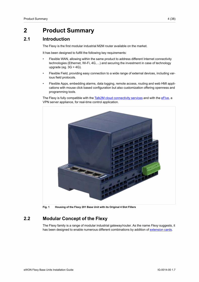
Fig. 1 Housing of the Flexy 201 Base Unit with its Original 4 Slot Fillers
2.2 Modular Concept of the FlexyThe Flexy family is a range of modular industrial gateway/router. As the name Flexy suggests, ithas been designed to enable numerous different combinations by addition of extension cards.
eWON Flexy Base Units Installation Guide IG-0014-00 1.7

Product Summary 5 (38)
Fig. 2 Modular Concept of the Flexy
1 Base unit2 Communication interface3 Main connector including power input terminals (1 DO and 2 DIs)4 Extension cards
2.2.1 Base UnitThe Flexy base units are available in 3 different versions (mother boards) depending on theircommunication interface:
Ethernet Switch Flexy 101 & 201
Serial & Ethernet Flexy 102 & 202
MPI & Ethernet Flexy 103 & 203
Each base unit features:
• 2 DIs and 1 DO.
• 4 free slots allowing the insertion of extension cards
Each base unit version is available as:
M2M Data Gateway Flexy 10x (without WAN / LAN / serial routing)
M2M Router Flexy 20x (full version)
See features matrix in Features of the Flexy, p. 6
eWON Flexy Base Units Installation Guide IG-0014-00 1.7

Product Summary 6 (38)
2.2.2 Extension CardsThe extension cards fit inside all the different base unit versions and extend the communicationfeatures by adding either:
• a WAN communication interface (Ethernet WAN, wireless modem, ...)
• a field communication interface (serial, IO card, …)
How the extension cards should be integrated in the eWON Flexy base units is explained in Ex-tension Cards, p. 21.
2.3 Features of the FlexyThe following section lists the different main features supported by the Flexy.
M2M Data Gateway(Flexy 10x)
M2M Router(Flexy 20x)
Open VPN ● ●
Talk2M connections ● ●Data acquisition protocols (IO Servers) ● ●
Alarm management and notification ● ●
Data logging ● ●
BASIC scripting ● ●
JAVA ETK ● ●Web server ● ●ViewON 4 Web HMI ● ●FTP client and server ● ●HTTP(S) client (Get & Post requests) ●
Ethernet to Serial gateway ●
Routing between Ethernet interfaces (WAN to LAN) ●
Routing features: IP forwarding, NAT, Port forwarding ●
2.4 General Specification of the Hardware PlatformCharacteristic ValueDesign Industrial design (24 VDC power supply, DIN Rail mounting, extended temperature)Processor ARM9Clock Backed up real time clock (RTC)
Backup battery has 10 years life expectancyEthernet Interface 4 LAN Ethernet ports 10/100 MbpsDigital Input 2Digital Output 1Mounting Latch for DIN rail EN50022-compliant
2.5 Typical applicationsThe Flexy is mostly used for
• Remote access of Ethernet, serial and MPI devices
• Industrial VPN router
• Remote metering and monitoring
eWON Flexy Base Units Installation Guide IG-0014-00 1.7

Product Summary 7 (38)
2.6 Types & Part NumbersAvailable Types
Routing capabilitiesCommunication Interface
4 Ethernet ports only 4 Ethernet ports + 1 seri-al port
4 Ethernet ports + 1 MPIport
M2M Data Gateway Flexy 101 Flexy 102 Flexy 103M2M Router Flexy 201 Flexy 202 Flexy 203
Available Part NumbersPart Number Type DescriptionFLEXY10100_00MA Flexy 101 M2M Data Gateway – 4 Ethernet portsFLEXY10200_00MA Flexy 102 M2M Data Gateway – 4 Ethernet ports + SerialFLEXY10300_00MA Flexy 103 M2M Data Gateway – 4 Ethernet ports + MPIFLEXY20100_00MA Flexy 201 M2M Router – 4 Ethernet portsFLEXY20200_00MA Flexy 202 M2M Router – 4 Ethernet ports + SerialFLEXY20300_00MA Flexy 203 M2M Router – 4 Ethernet ports + MPI
In the above table, the MA extension stands for “Multiple language A” (regrouping EN, FR, DEand IT). The part number syntax is explained in the Base Unit Label, p. 14.
eWON Flexy Base Units Installation Guide IG-0014-00 1.7

Safety, Environmental & Regulatory Information 8 (38)
3 Safety, Environmental & RegulatoryInformation
3.1 ScopeThe present section addresses safety, environmental & regulatory information for the eWONFlexy base units. They generally have a similar compliance frame but some aspects differ. Forexample, in the case of telecommunication extension cards, additional directives, standardsand instructions apply.
3.2 ESD Damage PreventionTo avoid possible damage to the base unit and / or extension card, please wait 30 seconds afterswitching off the equipment before inserting (or removing) an extension card.
Always use ESD precautions when handling extension cards and / or opened baseunit as they contain parts and assemblies susceptible to be damaged byelectrostatic discharge (ESD).
The printed circuit boards (PCBs) of the eWON Flexy base units described in the present docu-ment are partially exposed when slot fillers are removed to place extension cards. In order toavoid ESD damage, the product, when it is opened, must be handled with the necessary pre-caution including:
• Grounded ESD functional work surface
• Personal grounding
• Verification that the configuration is compatible with the firmware capabilities before beingoperated.
• Verification that the configuration complies with the energy point balance before operating(see Energy Demand Points (Extension Cards), p. 25).
The extension cards described in this document are modules exposing both sides of an elec-tronic printed circuit board. Therefore, they are packed in anti static ESD bags. In order to avoidESD damage, the product must be handled with the necessary precaution as described above.
3.3 Applicable Directives, Standards and ComplianceThe eWON Flexy base units belong to class A Information Technology Equipment (ITE). In adomestic environment, this product may cause radio interference in which case the user mighthave to take appropriate measures.
3.3.1 Conformity to European DirectivesThe eWON Flexy base units and their extension cards are in conformity with the following ECdirectives:
• RoHS Directive 2011/65/EU
• EMC Directive 2014/30/EU
• RE Directive 2014/53/EU1
eWON Flexy Base Units Installation Guide IG-0014-00 1.7
1. When applicable, the product conforms to the corresponding RE Directive articles: RF spectrum efficiency: Art 3 (2);EMC: Art. 3(1)(b); Safety: Art. (3)(1)(a)

Safety, Environmental & Regulatory Information 9 (38)
3.3.2 Applicable Safety StandardsThe eWON Flexy base units and their extension cards are in conformity with the following safetystandards:
• IEC/EN 60950-1
• UL 60950-1
• CSA-C22.2 No 60950-1-07
3.3.3 FCC ComplianceThe eWON Flexy base units and their extension cards comply with Part 15 of the FCC Rules.
Operating is subject to the following two conditions:
• This device may not cause harmful interference
• This device must accept any interference received, including interference that may causeundesired operation.
3.3.4 CertificationsThe eWON Flexy base units and their extension cards have been duly certified by authorizedbodies:
• UL Certificate of Compliance (COC) # 20121129-E350576
• CB certificate # DK-53957-UL
These certificates can be downloaded on www.ewon.biz/support
3.4 Reference Standards for Type TestsThe eWON Flexy base units and their extension cards have been fully validated on tempera-ture, vibration and shock against the requirements of the following standards:
Operating & Storage TemperatureTest nature Reference StandardCold test IEC 60068-2-1Dry heat test IEC 60068-2-2Temperatur change test IEC 60068-2-14Cyclic damp heat test IEC 60068-2-30
Vibration & Shock TestsTest nature Reference StandardProgrammable controllers test IEC 61131-2Vibration test (sinusoidal) IEC 60068-2-6Vibration test (broad-band random) IEC 60068-2-64Shock test IEC60068-2-27
eWON Flexy Base Units Installation Guide IG-0014-00 1.7

Safety, Environmental & Regulatory Information 10 (38)
3.5 Internal Battery3.5.1 Purpose and Reference
All eWON Flexy base units feature a small battery for RTC backup in case of power failure. Thelife expectancy of the battery is greater than 10 years starting from the product manufacturingdate.
The battery type is of CR2032. Only this type of battery delivered by HMS Industrial NetworksSA may be used to comply with the UL and safety standards. Please do not use any other bat-tery than the one referenced below:
• Replacement CR2032 Battery
• eWON part number: FAC90101_0000.
3.5.2 Battery Replacement Procedure
There is a risk of explosion if the battery is replaced by an incorrect type.
Before starting, make sure the necessary precautions to avoid ESD damage (see ESD DamagePrevention, p. 8) have been taken.
Be aware that insulated tweezers (e.g from manufacturer EREM model 249 SA, see below) areneeded to be able to handle the battery without short-circuiting it.The RTC battery is located on the mother board in the alignment of slot 3 starting from the leftas the eWON logo is on the right side.
Fig. 3 Battery Replacement
eWON Flexy Base Units Installation Guide IG-0014-00 1.7
Safety, Environmental & Regulatory Information 11 (38)
Here’s the procedure to replace the battery:
1. Power the unit off and wait 30 seconds before continuing the procedure.
2. For a practical access, it is recommended to remove all slot fillers and / or extension cards.
3. Carefully remove the battery from its holder and put the new one in place.
4. Check that the locking tab is correctly placed on top of the battery.
Do not dismantle, crush, puncture the battery or attempt to open the servicebattery as this can lead to severe injuries.
Do not dispose of batteries in fire or with household waste but according to instruc-tions. Consider the environment, check the battery recycling services available inyour region.
3.6 Field Implementation & Environmental Conditions3.6.1 Ingress Protection
The eWON Flexy base units have an IP20 protection grade. Therefore, the eWON Flexy baseunits are NOTsuited for outdoor mounting.
They have to be integrated in an electrical cabinet, protected from excessive heat, humidity anddust. Do not push any sharp object into the air vents or openings of the equipment.
3.6.2 Mounting RecommendationsThe normal mounting position of the Flexy is wall mounted on a horizontal Omega type DIN-rail(EN 50022).
To ensure a proper ventilation of the equipment, a free gap of at least 2 cm must be respectedin front of all ventilation openings of the unit.
In any other mounting position than the one explained here under, the specifiedtemperature has to be derated to -25°C to +40°C.
eWON Flexy Base Units Installation Guide IG-0014-00 1.7

Safety, Environmental & Regulatory Information 12 (38)
Fig. 4 Flexy Heat Ventilation
Here is the process how to mount / remove a unit from a DIN-rail:
• Mounting the unit on DIN-railPresent the unit in front of the DIN rail and tilt it upwards in order to hang it on the upperedge of the DIN rail by the hooks at the rear. Gently tilt the unit downwards until the slidelock snaps. The slide lock is located in the middle at the bottom of the unit (see MechanicalDimensions, p. 15).
• Removing the unit from DIN-railInsert a medium size screwdriver in the small slot of the slide lock located in the middle atthe bottom of the unit. Release the unit by pulling the slide lock downwards while gently tilt-ing the unit upwards. Free the unit by unhooking it from the upper rail edge (see Mechani-cal Dimensions, p. 15).
3.6.3 EarthingEarthing the Flexy is necessary to eliminate unwanted transients (lightning protection) and toconform to the EMC requirements.
Therefore, a functional earth (FE) terminal is available on the main connector as shown in MainConnector, p. 31. Connect this terminal directly to a low impedance ground. Shielded cableshave to be used for Ethernet and serial connectivity to comply with the EMC requirements.
A scheme of the Flexy isolation is available in Flexy Isolation Scheme, p. 35.
eWON Flexy Base Units Installation Guide IG-0014-00 1.7
Safety, Environmental & Regulatory Information 13 (38)
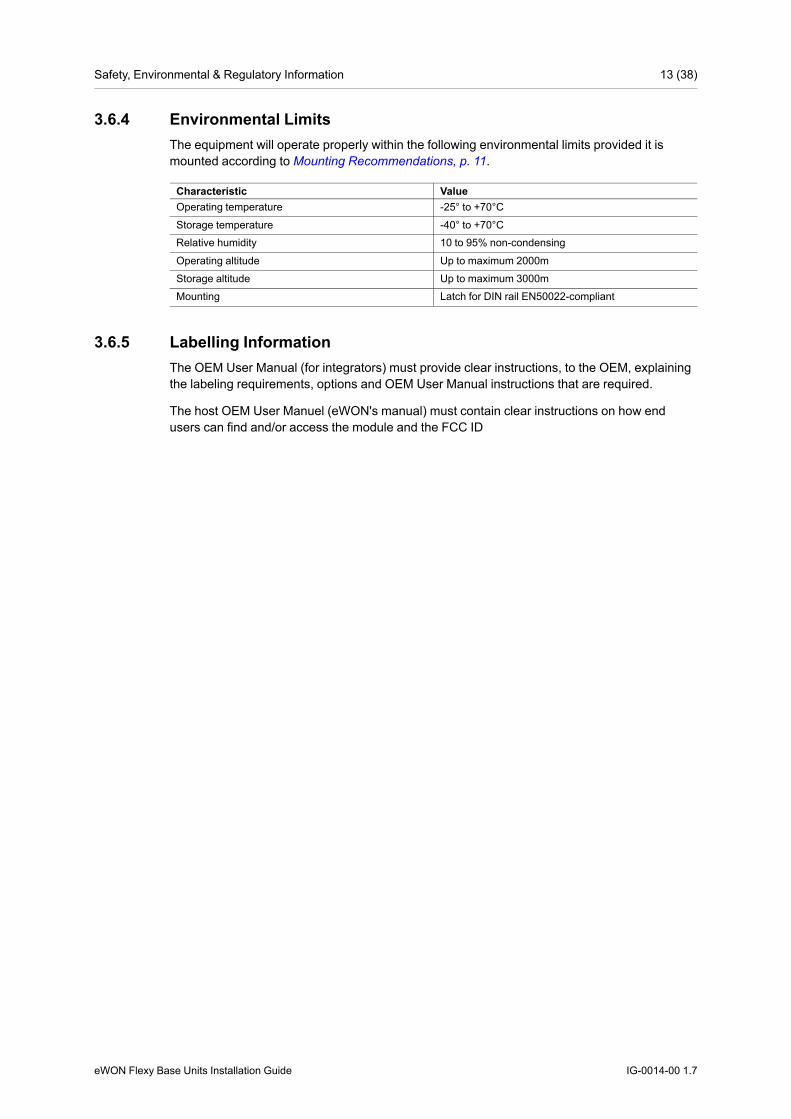
3.6.4 Environmental LimitsThe equipment will operate properly within the following environmental limits provided it ismounted according to Mounting Recommendations, p. 11.
Characteristic ValueOperating temperature -25° to +70°CStorage temperature -40° to +70°CRelative humidity 10 to 95% non-condensing
Operating altitude Up to maximum 2000mStorage altitude Up to maximum 3000mMounting Latch for DIN rail EN50022-compliant
3.6.5 Labelling InformationThe OEM User Manual (for integrators) must provide clear instructions, to the OEM, explainingthe labeling requirements, options and OEM User Manual instructions that are required.
The host OEM User Manuel (eWON's manual) must contain clear instructions on how endusers can find and/or access the module and the FCC ID
eWON Flexy Base Units Installation Guide IG-0014-00 1.7

Base Unit Hardware Description 14 (38)
4 Base Unit Hardware Description4.1 Base Unit Label
The identification label of the eWON Flexy base units is placed on the right hand side of thehousing. The different parts of the label are described below:
Fig. 5 Flexy 201 Label
Label DefinitionPN Part Number
(see syntax in Syntax of the Part Number, p. 14)SN Serial Number YYWW-SSSS-PP
YY = 2 last digits of production yearWW = production week numberSSSS = Sequential production numberPP = Product Code
MAC MAC address of the Ethernet adapterRating Power supply requirementsMarks CE, UL,... logos if applicable
Syntax of the Part NumberFLEXY12233_44AA/BB
Position(s) Description Acceptable valuesFLEXY Name of the eWON device model Only Flexy (constant)1 Single figure
Defines routing capabilities1 M2M Data Gateway2 M2M Router
22 Two figuresDefines the type of the motherboard
01 4 Ethernet ports02 1 Ethernet port & 1 Serial port03 1 Ethernet port & 1 MPI port
33 Two figuresDefines the primary software option
00 No primary software option
44 Two figuresDefines the secondary softwareoption
00 No secondary software option
AA Two capital lettersDefines the firmware language
MA EN + FR + DE + IT
/BB Two capital lettersDefines the model type
S Compliance with UL / IEC / EN 60950Standard
H Compliance with Hazardous Location (C1D2)
MarksMarks Description
Conformité Européenne or European Conformity (EC)
UL Recognized - Underwriters Laboraties
eWON Flexy Base Units Installation Guide IG-0014-00 1.7
Base Unit Hardware Description 15 (38)
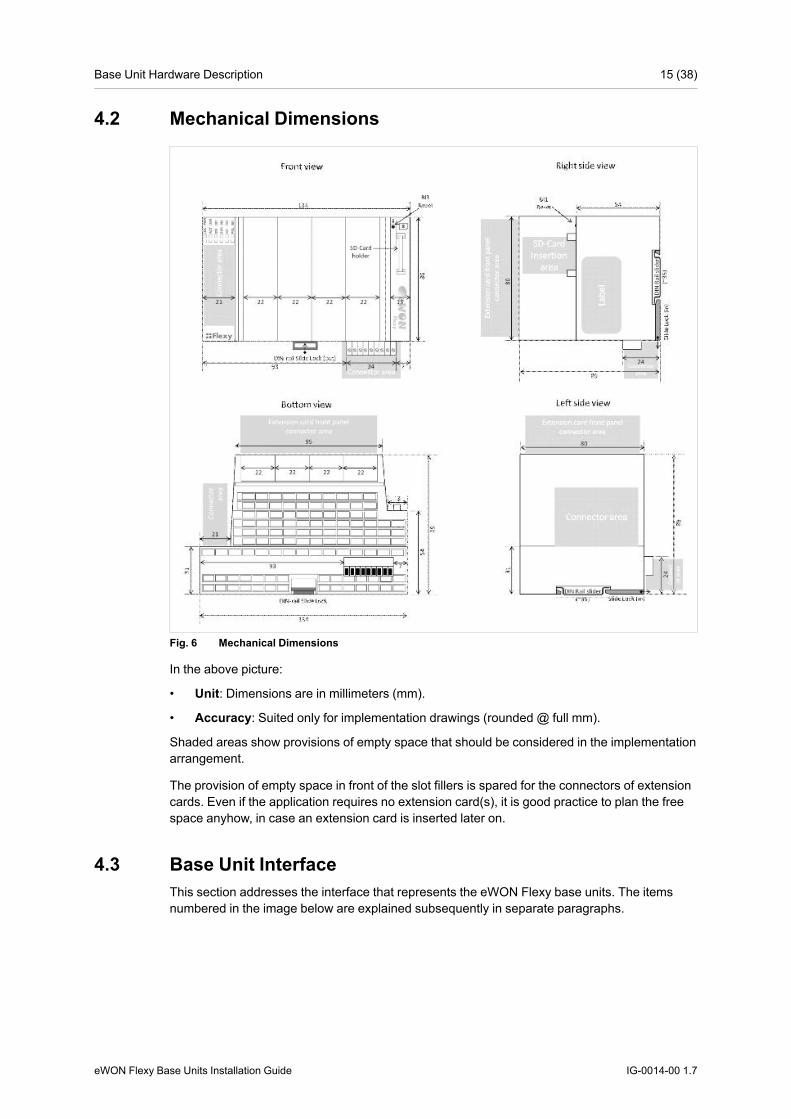
4.2 Mechanical Dimensions
Fig. 6 Mechanical Dimensions
In the above picture:
• Unit: Dimensions are in millimeters (mm).
• Accuracy: Suited only for implementation drawings (rounded @ full mm).
Shaded areas show provisions of empty space that should be considered in the implementationarrangement.
The provision of empty space in front of the slot fillers is spared for the connectors of extensioncards. Even if the application requires no extension card(s), it is good practice to plan the freespace anyhow, in case an extension card is inserted later on.
4.3 Base Unit InterfaceThis section addresses the interface that represents the eWON Flexy base units. The itemsnumbered in the image below are explained subsequently in separate paragraphs.
eWON Flexy Base Units Installation Guide IG-0014-00 1.7

Base Unit Hardware Description 16 (38)
Fig. 7 Base Unit Interface
1 LED panel2 RESET button - BI13 SD card slot4 Main connector
Used to connect the power supply and the digital I/O5 4 slots fillers
Can be removed and replaced by extension cards6 Main board communication interfaces
Depends on the base unit type (in the above picture: 4 Ethernet Ports)
4.3.1 LED PanelThe LED panel displays the system status and is located opposite the eWON logo. The follow-ing table explains the common LEDs of all base units.
Fig. 8 LED Panel Example of a Flexy
Label DefinitionPWR Power
Steady green = unit is powered onUSR User
Blinking green slowly = Unit is okRed pattern = special attention required
DI1 Digital IN 1Green = ON : Signal on Input 1 detected
DI2 Digital IN 2Green = ON : Signal on Input 2 detected
DO Digital outputGreen = ON : Signal on Output detected
BI1 Button BI1 inputSteady green = reset button is being pressed
Specific LEDs of each base unit model are ad-dressed in distinct chapters.
4.3.2 Reset ButtonThe reset button allows the reset of the Flexy partially (Reset Level 1) or completely (Reset Lev-el 2). For the reset procedures check Resetting the Flexy, p. 28.
eWON Flexy Base Units Installation Guide IG-0014-00 1.7
Base Unit Hardware Description 17 (38)
4.3.3 SD Card SlotThe SD card can be used for two purposes:
• Easy Commissioning: Configure a Flexy and perform actions such as a firmware upgrade /downgrade, recovery, restore a backup, Talk2M account integration, ...
• Extended User Memory: Named as the EUM card, it increases the user memory capacityof the Flexy.
For more information on each of those possibilities, easy commissioning or EUM, please referto the Related Documents, p. 3.
4.3.4 Main ConnectorThe Flexy is powered via its main connector using a male connector (a mating female connectorwith screw terminals is delivered with the eWON Flexy base units).
For details see Main Connector, p. 31.
4.3.5 Four Slots for ExtensionsThe slot fillers can be removed to add extension cards. A general overview of the available ex-tension cards is available in the Extension Cards, p. 33.
It is recommended to never leave a slot empty. Either a slot filler or an extension card should al-ways be inserted in the Flexy.
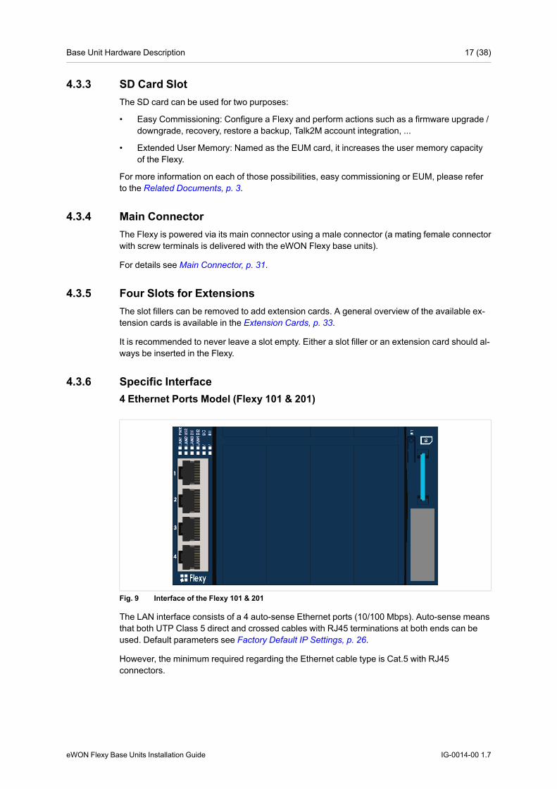
4.3.6 Specific Interface4 Ethernet Ports Model (Flexy 101 & 201)
Fig. 9 Interface of the Flexy 101 & 201
The LAN interface consists of a 4 auto-sense Ethernet ports (10/100 Mbps). Auto-sense meansthat both UTP Class 5 direct and crossed cables with RJ45 terminations at both ends can beused. Default parameters see Factory Default IP Settings, p. 26.
However, the minimum required regarding the Ethernet cable type is Cat.5 with RJ45connectors.
eWON Flexy Base Units Installation Guide IG-0014-00 1.7
Base Unit Hardware Description 18 (38)
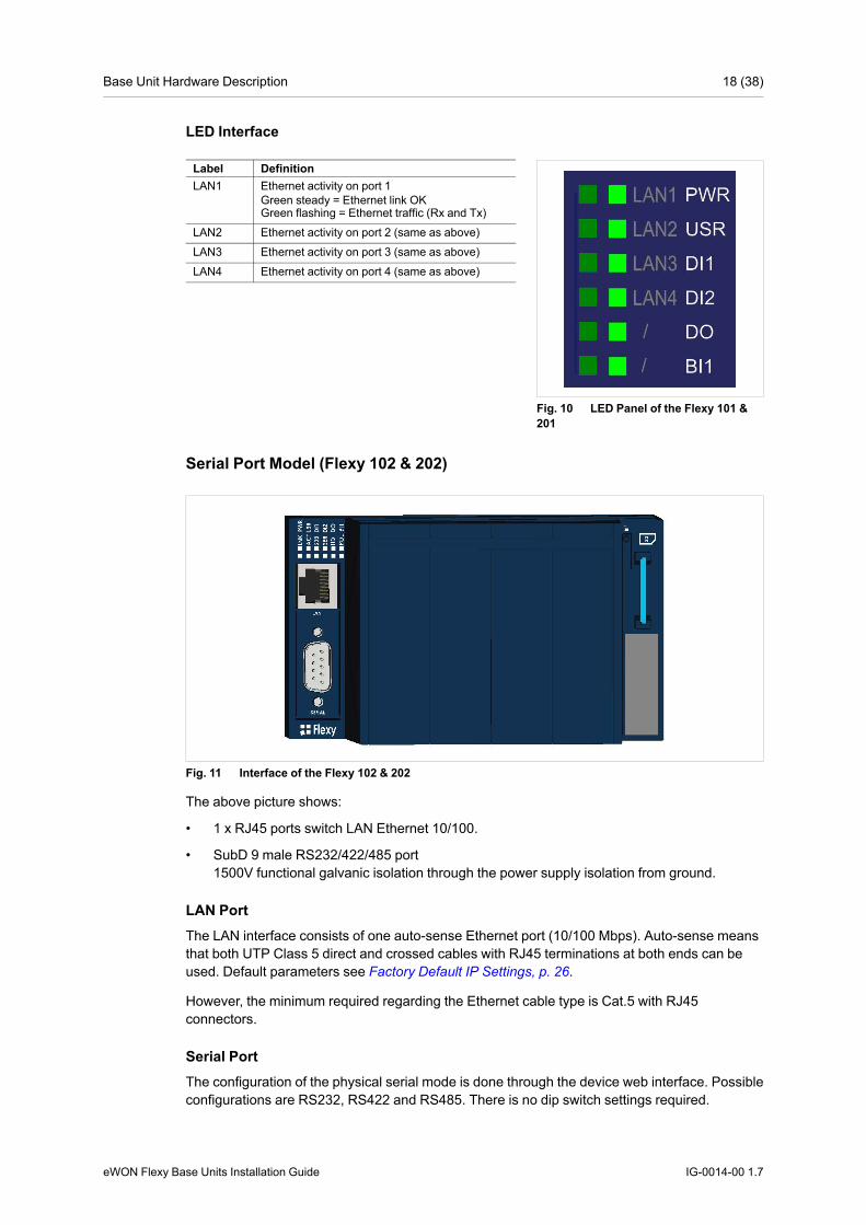
LED Interface
Fig. 10 LED Panel of the Flexy 101 &201
Label DefinitionLAN1 Ethernet activity on port 1
Green steady = Ethernet link OKGreen flashing = Ethernet traffic (Rx and Tx)
LAN2 Ethernet activity on port 2 (same as above)LAN3 Ethernet activity on port 3 (same as above)LAN4 Ethernet activity on port 4 (same as above)
Serial Port Model (Flexy 102 & 202)
Fig. 11 Interface of the Flexy 102 & 202
The above picture shows:
• 1 x RJ45 ports switch LAN Ethernet 10/100.
• SubD 9 male RS232/422/485 port1500V functional galvanic isolation through the power supply isolation from ground.
LAN PortThe LAN interface consists of one auto-sense Ethernet port (10/100 Mbps). Auto-sense meansthat both UTP Class 5 direct and crossed cables with RJ45 terminations at both ends can beused. Default parameters see Factory Default IP Settings, p. 26.
However, the minimum required regarding the Ethernet cable type is Cat.5 with RJ45connectors.
Serial PortThe configuration of the physical serial mode is done through the device web interface. Possibleconfigurations are RS232, RS422 and RS485. There is no dip switch settings required.
eWON Flexy Base Units Installation Guide IG-0014-00 1.7

Base Unit Hardware Description 19 (38)
LED Interface
Fig. 12 LED Panel of the Flexy 102 &202
Label DefinitionLNK Ethernet link
Green steady = Ethernet link OKACT Ethernet activity
Green flashing = Ethernet traffic (Rx & Tx)232 RS232 mode
Green steady = port configured in RS232 modeSER Green flashing = RX/TX traffic on serial portHD Half duplex
Green steady = configured in RS485 modePOL Polarization resistors
Green steady = Polarization and termination ON
MPI Port Model (Flexy 103 & 203)
Fig. 13 Interface of the Flexy 103 & 203
The above picture shows:
• 1 x RJ45 ports switch LAN Ethernet 10/100.
• SubD 9 female MPI-port1500V functional galvanic isolation through the power supply isolation from ground.
LAN PortThe LAN interface consists of one auto-sense Ethernet port (10/100 Mbps). Auto-sense meansthat both UTP Class 5 direct and crossed cables with RJ45 terminations at both ends can beused. Default parameters see Factory Default IP Settings, p. 26.
However, the minimum required regarding the Ethernet cable type is Cat.5 with RJ45connectors.
MPI PortThe MPI - Profibus port allows the connection to an MPI or Profibus network. No further hard-ware configuration is required.
eWON Flexy Base Units Installation Guide IG-0014-00 1.7

Base Unit Hardware Description 20 (38)
LED Interface
Fig. 14 LED Panel of the Flexy 103 &203
Label DefinitionLNK Ethernet link
Green steady = Ethernet link OKACT Ethernet activity
Green flashing = Ethernet traffic (Rx & Tx)MPI MPI status
Green flashing = TX activity on the MPI portMTK MPI token
Green steady = Hold Token in MPI operationmode
eWON Flexy Base Units Installation Guide IG-0014-00 1.7

Extension Cards 21 (38)
5 Extension Cards5.1 Base Unit Slot Compatibility
The eWON Flexy base units feature two type of slots :
• The type-A slots are the two first slots starting from the left
• The type-B slots are the two last slots
Fig. 15 Flexy Slot Compatibility
Some cards fit in both type-A and type-B slots. Others don't. Cards that fit in only one type ofslot have a mechanical Poka-Yoke security.
The reference code of the Flexy extension cards includes a letter that defines their compatibilityeither with “A” slots, “B” slots or both.
• FLA xxxx - designates cards that fit into “A” slots
• FLB xxxx - designates cards that fit into “B” slots
• FLX xxxx - designates cards that fit into both “A” and “B” slots
In addition to the card reference, each type of extension card bears a visual compatibility sym-bol on its front panel.
eWON Flexy Base Units Installation Guide IG-0014-00 1.7

Extension Cards 22 (38)
Fig. 16 Slot Compatibility Markings
Indica-tion
Design Location
1 ●●○○ 2 first slots only - Type-A2 ●●●● Any slot - Type-X3 ○○●● 2 last slots only - Type-B
5.2 Extension Card Insertion
Wait 30 seconds after turning off the equipment before inserting (or removing) anextension card in order to avoid possible damage to the eWON Flexy base unitsand the extension cards.
Remove the slot filler of the location the new card will be inserted. To do this, press on both endsof the cover, note that the hooks are off-centered.
Insert the extension card carefully and slide it down until the hook clicks. Make sure the card iscompletely inserted. DO NOT insist if a resistance is felt when trying to insert the card, it prob-ably means the extension card is being placed in a wrong slot. In such case, check slot compat-ibility of the relevant extension card. Refer to Base Unit Slot Compatibility, p. 21.
eWON Flexy Base Units Installation Guide IG-0014-00 1.7
Extension Cards 23 (38)
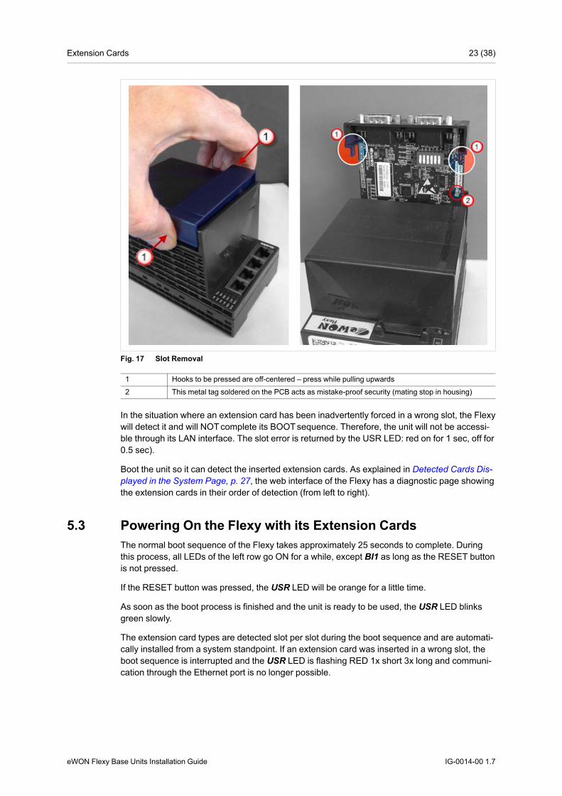
Fig. 17 Slot Removal
1 Hooks to be pressed are off-centered – press while pulling upwards2 This metal tag soldered on the PCB acts as mistake-proof security (mating stop in housing)
In the situation where an extension card has been inadvertently forced in a wrong slot, the Flexywill detect it and will NOTcomplete its BOOTsequence. Therefore, the unit will not be accessi-ble through its LAN interface. The slot error is returned by the USR LED: red on for 1 sec, off for0.5 sec).
Boot the unit so it can detect the inserted extension cards. As explained in Detected Cards Dis-played in the System Page, p. 27, the web interface of the Flexy has a diagnostic page showingthe extension cards in their order of detection (from left to right).
5.3 Powering On the Flexy with its Extension CardsThe normal boot sequence of the Flexy takes approximately 25 seconds to complete. Duringthis process, all LEDs of the left row go ON for a while, except BI1 as long as the RESET buttonis not pressed.
If the RESET button was pressed, the USR LED will be orange for a little time.
As soon as the boot process is finished and the unit is ready to be used, the USR LED blinksgreen slowly.
The extension card types are detected slot per slot during the boot sequence and are automati-cally installed from a system standpoint. If an extension card was inserted in a wrong slot, theboot sequence is interrupted and the USR LED is flashing RED 1x short 3x long and communi-cation through the Ethernet port is no longer possible.
eWON Flexy Base Units Installation Guide IG-0014-00 1.7
Extension Cards 24 (38)
5.4 Multiple Extension Cards5.4.1 Detection Order
The boot sequence of the Flexy includes an automated detection of the inserted extensioncards. This detection is done sequentially, slot per slot starting from left to right (when holdingthe Flexy with its logo on the right side).
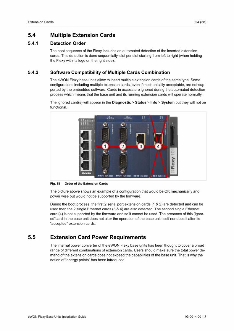
5.4.2 Software Compatibility of Multiple Cards CombinationThe eWON Flexy base units allow to insert multiple extension cards of the same type. Someconfigurations including multiple extension cards, even if mechanically acceptable, are not sup-ported by the embedded software. Cards in excess are ignored during the automated detectionprocess which means that the base unit and its running extension cards will operate normally.
The ignored card(s) will appear in the Diagnostic > Status > Info > System but they will not befunctional.
Fig. 18 Order of the Extension Cards
The picture above shows an example of a configuration that would be OK mechanically andpower wise but would not be supported by the firmware.
During the boot process, the first 2 serial port extension cards (1 & 2) are detected and can beused then the 2 single Ethernet cards (3 & 4) are also detected. The second single Ethernetcard (4) is not supported by the firmware and so it cannot be used. The presence of this “ignor-ed”card in the base unit does not alter the operation of the base unit itself nor does it alter its“accepted” extension cards.
5.5 Extension Card Power RequirementsThe internal power converter of the eWON Flexy base units has been thought to cover a broadrange of different combinations of extension cards. Users should make sure the total power de-mand of the extension cards does not exceed the capabilities of the base unit. That is why thenotion of “energy points” has been introduced.
eWON Flexy Base Units Installation Guide IG-0014-00 1.7

Extension Cards 25 (38)
5.5.1 Available Energy Points (Base Unit)Each base unit type has a certain amount of available energy points.
These available energy points depend on the temperature range in which the equipment will beused. Considering the fact very few applications require the equipment to actually work between50° and 70°C, the available energy points per base unit type are specified for both up to 50°Cmax. and up to 70°C max.:
Available Energy Points per Base Unit TypeEthernetFlexy 101 & 201
SerialFlexy 102 & 202
MPIFlexy 103 & 203
Available energy points(max. 50°C)
29 30 31
Available energy points(max. 70°C)
20 21 22
5.5.2 Energy Demand Points (Extension Cards)Each extension card requires a certain amount of energy demand points.
These energy demand points per extension card type are specified in the table of ExtensionCards, p. 33.
Example of Energy Demand Points2 serial portsFLA 3301
Single EthernetFLX 3101
3G GSMFLB 3202
Energy demande points 1 1 10
5.5.3 Power Balance Check ExampleConsidering the configuration shown in the second picture of Base Unit Slot Compatibility, p. 21.
Energy points(max. 50°C)
Energy points(max. 70°C)
Available energy points for base unit: Flexy 201 29 20Energy demand for 2 serial ports card: FLA 3301 1 1Energy demand for single Ethernet card: FLX 3101 1 1Energy demand for 3G GSM card: FLB 3202 10 10Energy Balance 17 8
Both results are higher than 0 which means that this combination works.
eWON Flexy Base Units Installation Guide IG-0014-00 1.7

IP Address & Access to the Web Configuration 26 (38)
6 IPAddress & Access to the Web Configuration6.1 Factory Default IP Settings
Characteristics ValuesLAN IP address 10.0.0.53LAN subnet mask 255.255.255.0Gateway 0.0.0.0
Since firmware version 10, the WAN IP address is set by default in DHCP mode.
6.2 Powering OnPower the unit on and wait approximately 25 seconds until the boot process is completed.
After a successful boot process the USR LED is blinking green slowly.
If the USR LED is blinking red according to a given pattern, it indicates an interruption of theboot process due to a problem. The most frequent issues are:
• an extension card is inserted in a wrong slot: USR LED blinking pattern is red 1x short, 3xlong
• a duplicate IP address was detected on the LAN network: USR LED blinking pattern is red1x short, 1x long
For other LED patterns in case of error, please refer to the RG-0001-00: General ReferenceGuide.
6.3 Connecting to the LAN IPAddressEstablish the first communication with the Flexy by using eWON companion tool eBuddy whichcan be downloaded from www.ewon.biz/support.
Connect one of the LAN ports of the Flexy to the computer point-to-point or through a networkprovided the default IP address of the Flexy will not conflict with another connected device.
Start the eBuddy application. The application scans through the Ethernet adapter network andretrieves the connected eWON devices displaying the IP address, subnet mask and serialnumber.
The utility also allows the modification of the default IP address without being necessarily in thesame network range. To do so, follow this process:
1. Start the eBuddy utility
2. Optional: Highlight the row representing the device which IP address needs to be modified
3. Click on the button “Set IP” from the top bar menu or hit F2 keyboard shortcut
4. If step 2 has been fulfilled, the serial number of the selected device appears in the newpopup. If not, indicate the serial number of the device that needs to be modified. Click Next
5. Indicate the new IP address and its subnet mask. By clicking Next, eBuddy sends the com-mand to the device to change its IP address and to reboot
6. Wait until the reboot has ended to reach the Flexy on its new IP address
eWON Flexy Base Units Installation Guide IG-0014-00 1.7
IP Address & Access to the Web Configuration 27 (38)
6.4 Web InterfaceWhile the computer is connected to a LAN port of the Flexy, open an Internet browser and reachthe Flexy web server which URL is the LAN IP address of the Flexy (default is 10.0.0.53).
Another way to access the web panel of the Flexy is by using eBuddy with its EZ DHCP feature.For more info, refer to AUG-0063-00: eBuddy.
Before beginning the configuration of the Flexy, an authentication is required.
Default login & password are both adm. For security reasons, default passwordmust be modified. To change it, go to Configuration > Users Setup and doubleclick on the adm entry to edit its parameters. Enter the new password twice andclick Save.
At the very first boot of the Flexy or after a reset level 2 and after successfully logging in, an in-terface language selection will be proposed.
A configuration wizard will be proposed afterwards which sets the configuration of the Flexy butalso the connection to the Talk2M environment.
On eWON website, a Quick Start Guide can be found which helps in the configuration of theFlexy.
6.4.1 Detected Cards Displayed in the System PageThe System page allows to check the status of the system including detected extension cards.
To access the system status summary, click on Diagnostic > Status > System Info > System.
eWON Flexy Base Units Installation Guide IG-0014-00 1.7
Resetting the Flexy 28 (38)
7 Resetting the FlexyThe reset button BI1 is located on the right side of the eWON Flexy base units (see Reset But-ton, p. 16). The reset function of this button is active only if pressed while powering on. TheFlexy features two type of reset levels. A table with the impacted configuration zones per resetlevel can be found in Reset Impact Matrix, p. 29.
7.1 Normal Boot SequenceThe normal boot sequence of the Flexy takes approximately 25 seconds to complete. Duringthis process, all LEDs of the left row go ON for a while, except BI1 as long as the RESET buttonis not pressed.
If the RESET button was pressed, the USR LED will be orange for a little time.
As soon as the boot process is finished and the unit is ready to be used, the USR LED blinksgreen slowly.
7.2 First Level Reset (User Reset)The first level reset consists in formatting only the “user files” part of the non volatile memory.This type of reset does not modify the communication parameters of the Flexy.
How to generate a first level reset:
1. Power the unit OFF and ON again
2. Immediately press and maintain the reset button. The LED labeled BI1 turns ON
3. Wait approximately 30 seconds until the USR LED blinks red 1x per second
4. Immediately release the button. The LED labeled BI1 turns OFF. If the button keeps beingpressed at this point, the second level reset will be engaged
5. Wait approximately 30 seconds until the reset procedure is completed.
6. The Flexy restarts automatically and the unit is ready to be used, the USR LED blinksgreen slowly.
7.3 Second Level Reset (Factory Reset)This second level reset formats all non volatile memories and erases the Flexy back to its fac-tory defaults. This operation consists in 3 steps:
• Erasement of all non volatile memories, including all COM parameters and IP addresses
• Full hardware auto test with result shown by the USR LED
• Return to factory configuration (default one)
How to generate a second level reset:
1. Power the unit OFF and ON again
2. Immediately press and maintain the reset button. The LED labeled BI1 turns ON
3. Wait approximately 35 seconds until the USR LED remains red steady
4. When this state is reached, release the button. The LED labeled BI1 turns OFF
5. It takes no longer than 5 seconds to complete.
eWON Flexy Base Units Installation Guide IG-0014-00 1.7

Resetting the Flexy 29 (38)
6. Check if the auto test is successful, the USR LED blinks red following a pattern of 200msON and 1,5 sec OFF. The Flexy does not restart in normal mode by itself and remains inthis diagnose mode.
7. Power the Flexy OFF and ON again to reboot the unit in normal mode. As described be-fore, the Flexy returns to its default COM parameters and factory IP addresses (defaultLAN IP: 10.0.0.53) after this second level reset is performed.
If a different pattern than the successful auto test one is displayed then this pattern reflects anissue.
The pattern starts with 200ms ON (beginning of the pattern) followed by OFF and a certainnumber of times 1 sec ON which allows to identify the nature of the detected problem. Pleasewrite down the observed pattern and contact the local distributor referring to the pattern error.
7.4 Reset Impact MatrixErased or Reset Preserved
Impact Reset Level 1User Reset
User(s) LAN IP address + maskadm password Internet accessTags Language settingsIO Server config COM settings (modem, etc)Gateway config Talk2M config + keyeWON Identification Proxy configurationUser Web site Memory configurationUser Scripts
Impact Reset Level 2Factory Reset
LAN IP address + mask NothingInternet accessLanguage settingsCOM settings (modem, etc)Talk2M config + keyProxy configurationMemory configurationUser(s)adm passwordTagsIO Server configGateway configeWON IdentificationUser Web siteUser Scripts
eWON Flexy Base Units Installation Guide IG-0014-00 1.7

This page intentionally left blank
Appendix A: Connector Pinout & Related Specifications 31 (38)
A Connector Pinout & Related SpecificationsA.1 Main Connector
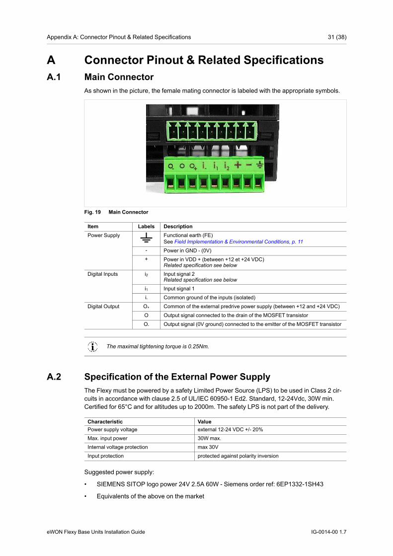
As shown in the picture, the female mating connector is labeled with the appropriate symbols.
Fig. 19 Main Connector
Item Labels DescriptionPower Supply Functional earth (FE)
See Field Implementation & Environmental Conditions, p. 11- Power in GND - (0V)+ Power in VDD + (between +12 et +24 VDC)
Related specification see below
Digital Inputs i2 Input signal 2Related specification see below
i1 Input signal 1i- Common ground of the inputs (isolated)
Digital Output O+ Common of the external predrive power supply (between +12 and +24 VDC)O Output signal connected to the drain of the MOSFET transistorO- Output signal (0V ground) connected to the emitter of the MOSFET transistor
The maximal tightening torque is 0.25Nm.
A.2 Specification of the External Power SupplyThe Flexy must be powered by a safety Limited Power Source (LPS) to be used in Class 2 cir-cuits in accordance with clause 2.5 of UL/IEC 60950-1 Ed2. Standard, 12-24Vdc, 30W min.Certified for 65°C and for altitudes up to 2000m. The safety LPS is not part of the delivery.
Characteristic ValuePower supply voltage external 12-24 VDC +/- 20%Max. input power 30W max.Internal voltage protection max 30VInput protection protected against polarity inversion
Suggested power supply:
• SIEMENS SITOP logo power 24V 2.5A 60W - Siemens order ref: 6EP1332-1SH43
• Equivalents of the above on the market
eWON Flexy Base Units Installation Guide IG-0014-00 1.7

Appendix A: Connector Pinout & Related Specifications 32 (38)
A.3 Serial Interface (Flexy 102 & 202)Characteristic ValuePhysical modes RS232/422/485 (1500V galvanic isolation through the power supply isolation from ground)Polarization 330 Ω (if polarization & termination are activated)Termination 120 Ω (if polarization & termination are activated)
SUBD9 maleconnector pin-out (Flexy side)
Pin # RS232 RS485 RS4221 - - -2 RXD - Rx+3 TXD A+ Tx+4 - - -5 GND GND GND6 - - -7 RTS - Rx-8 CTS B- Tx-9 - - -
A.4 MPI Interface (Flexy 103 & 203)Characteristic ValuePhysical mode MPI (1500V galvanic isolation through the power supply isolation from ground)Baud rates From 9,6 kBauds to 12,0 MBaudsPolarization 100 kΩTermination NoneSUBD9 female connec-tor pinout (Flexy side)
Pin # MP1 -2 -3 B+4 -5 GND6 -7 -8 A-9 -
eWON Flexy Base Units Installation Guide IG-0014-00 1.7
Appendix B: Flexy Products Overview 33 (38)
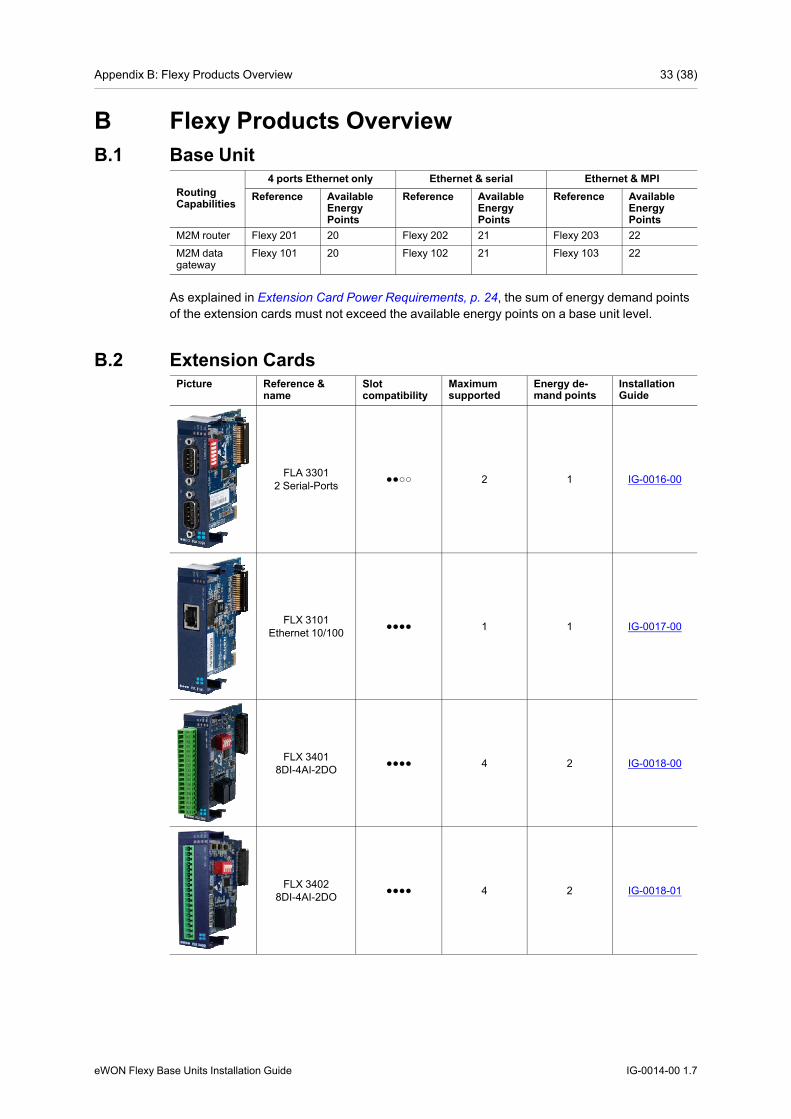
B Flexy Products OverviewB.1 Base Unit
RoutingCapabilities
4 ports Ethernet only Ethernet & serial Ethernet & MPIReference Available
EnergyPoints
Reference AvailableEnergyPoints
Reference AvailableEnergyPoints
M2M router Flexy 201 20 Flexy 202 21 Flexy 203 22M2M datagateway
Flexy 101 20 Flexy 102 21 Flexy 103 22
As explained in Extension Card Power Requirements, p. 24, the sum of energy demand pointsof the extension cards must not exceed the available energy points on a base unit level.
B.2 Extension CardsPicture Reference &
nameSlotcompatibility
Maximumsupported
Energy de-mand points
InstallationGuide
FLA 33012 Serial-Ports ●●○○ 2 1 IG-0016-00
FLX 3101Ethernet 10/100 ●●●● 1 1 IG-0017-00
FLX 34018DI-4AI-2DO ●●●● 4 2 IG-0018-00
FLX 34028DI-4AI-2DO ●●●● 4 2 IG-0018-01
eWON Flexy Base Units Installation Guide IG-0014-00 1.7

Appendix B: Flexy Products Overview 34 (38)
Picture Reference &name
Slotcompatibility
Maximumsupported
Energy de-mand points
InstallationGuide
FLB 32023G GSM ○○●● 1 10 IG-0019-00
FLB 32044G EU ○○●● 1 8 IG-0026-00
FLB 3271WI-FI ○○●● 1 4 IG-0020-00
FLA 3501PSTN ●●○○ 1 2 IG-0021-00
FLB3601USB ○○●● 1 9 IG-0024-00
Since July 2016, the FLX 3401 has been tagged as end of life and is replaced bythe FLX 3402.
As explained in Software Compatibility of Multiple Cards Combination, p. 24, the number ofcards of the same type supported by the firmware is indicated in this table.
As explained in Extension Card Power Requirements, p. 24, the sum of energy demand pointsof the extension cards must not exceed the available energy points on a base unit level.
eWON Flexy Base Units Installation Guide IG-0014-00 1.7

Appendix C: Flexy Isolation Scheme 35 (38)
C Flexy Isolation SchemeC.1 Base Unit
Flexy 201 Flexy 202 & 203Connector shielding Earth connectedEthernet signals Isolated from DGNG with a transformerMPI / serial ports / Isolated from PGND only
Serial ports GND = DGND
Fig. 20 Isolation Scheme for the Base Unit
Based on the above picture:
• External and internal power supplies are isolated from each other (1.5kV)
• DI signals: isolated from DO signals, PGND and DGND (optocoupler)
• DO signals: isolated from DI signals, PGND and DGND (optocoupler)
• Earth is isolated from external and internal power supplies
C.2 Extension CardsC.2.1 FLB 320x – Cellular
DGND = GND RF from SMA connector
Avoid external connections between GND RF and Earth.
C.2.2 FLX 3101 – WAN EthernetConnector shielding: Earth connected
Ethernet signals: isolated from DGND with a transformer
eWON Flexy Base Units Installation Guide IG-0014-00 1.7

Appendix C: Flexy Isolation Scheme 36 (38)
C.2.3 FLX 3271 – Wi-FiDGND = GND RF from SMA connector
Avoid external connections between GND RF and Earth.
C.2.4 FLX 340x – I/ODO signals: isolated relays outputs
DI signals: isolated from DGND (optocoupler)
AI signals: isolated from PGND only
AI-GND = DGND
C.2.5 FLA 3301 – Dual Serial PortsSerial port signals: isolated from PGND only
Connector shielding: connected to Earth
Serial ports GND = DGND
C.2.6 FLB 3601 – 3 USB PortsUSB signals: isolated from PGND only
Connector shielding: connected to Earth
Due to USB connector design, Earth-DGND isolation is limited to 500V when the USB exten-sion card is inserted
AI-GND = DGND
eWON Flexy Base Units Installation Guide IG-0014-00 1.7

This page intentionally left blank

last page
© 2017 HMS Industrial Networks ABBox 4126300 04 Halmstad, Sweden
[email protected] IG-0014-00 1.7.5094 / 2017-09-01T09:31:52