EVOS M5000 Imaging System - assets.thermofisher.com · Peel the protective paper from the UV light...
10
For Research Use Only. Not for use in diagnostic procedures. EVOS ™ M5000 Imaging System Pub. No. MAN0017783 Doc. Part No. 710208 Rev. B.0 Note: For safety and biohazard guidelines, see the “Safety” appendix in the EVOS ™ M5000 Imaging System User Guide (Pub. No. MAN0017563). Read the Safety Data Sheets (SDSs) and follow the handling instructions. Wear appropriate protective eyewear, clothing, and gloves. Standard items included.................................................................................................... 1 Operating environment and site requirements ................................................................. 2 Instrument exterior components and mechanical controls ............................................... 3 Prepare for installation ...................................................................................................... 5 Install the instrument ......................................................................................................... 5 Related documentation and support............................................................................... 10 Standard items included EVOS ™ M5000 Imaging System • EVOS ™ M5000 Imaging System, includes the following components and pre-installed accessories: - 18.5 in articulated LCD monitor (1920 ×1080 pixel resolution) - Embedded PC (4 GB RAM) - Light cube shipping restraint (remove before use) - Stage lock pin (remove before use) - EVOS ™ Condenser Light Shield, 110 mm - Light cube tool (remove before use) - Blank light cube (remove before use) - LED light cubes, as ordered - Objectives, as ordered EVOS ™ M5000 Accessories • EVOS ™ M5000 Accessories Kit (located in the instrument box), contains: - Wireless mouse and keyboard - USB receiver (for wireless mouse and keyboard connection) - USB Wi-Fi adapter (for wireless network connection to Thermo Fisher Cloud applications) - USB 3.0 flash drive, 16 GB (for image storage, and preloaded with user documentation) - EVOS ™ Vessel Holder, two 25 × 75 mm slides (Cat. No. AMEPVH001) - EVOS ™ Vessel Holder, universal (Cat. No. AMEPVH009) - EVOS ™ Calibration Slide (Cat. No. AMEP4720) - EVOS ™ Light Shield Box - UV shield assembly
Transcript of EVOS M5000 Imaging System - assets.thermofisher.com · Peel the protective paper from the UV light...

For Research Use Only. Not for use in diagnostic procedures.
EVOS™ M5000 Imaging System Pub. No. MAN0017783 Doc. Part No. 710208 Rev. B.0
Note: For safety and biohazard guidelines, see the “Safety” appendix in the EVOS™ M5000
Imaging System User Guide (Pub. No. MAN0017563). Read the Safety Data Sheets (SDSs) and follow the handling instructions. Wear appropriate protective eyewear, clothing, and gloves.
Standard items included .................................................................................................... 1
Operating environment and site requirements ................................................................. 2
Instrument exterior components and mechanical controls ............................................... 3
Prepare for installation ...................................................................................................... 5
Install the instrument......................................................................................................... 5
Related documentation and support ............................................................................... 10
Standard items included EVOS™ M5000 Imaging System
• EVOS™ M5000 Imaging System, includes the following components and pre-installed accessories:
- 18.5 in articulated LCD monitor (1920 ×1080 pixel resolution)
- Embedded PC (4 GB RAM)
- Light cube shipping restraint (remove before use)
- Stage lock pin (remove before use)
- EVOS™ Condenser Light Shield, 110 mm
- Light cube tool (remove before use)
- Blank light cube (remove before use)
- LED light cubes, as ordered
- Objectives, as ordered
EVOS™ M5000 Accessories
• EVOS™ M5000 Accessories Kit (located in the instrument box), contains:
- Wireless mouse and keyboard
- USB receiver (for wireless mouse and keyboard connection)
- USB Wi-Fi adapter (for wireless network connection to Thermo Fisher Cloud applications)
- USB 3.0 flash drive, 16 GB (for image storage, and preloaded with user documentation)
- EVOS™ Vessel Holder, two 25 × 75 mm slides (Cat. No. AMEPVH001)
- EVOS™ Vessel Holder, universal (Cat. No. AMEPVH009)
- EVOS™ Calibration Slide (Cat. No. AMEP4720)
- EVOS™ Light Shield Box
- UV shield assembly

2 EVOS™ M5000 Imaging System Installation Guide
- Condenser Slider, Block (Cat. No. AMEP4688)
- Condenser Slider, 4X Pupil (Cat. No. AMEP4738)
- Condenser Slider, Diffusion for Brightfield Applications (Cat. No. AMEPDFS1)
- Universal power supply (12 V, 5 A) and power cord (type B, North America)
- EVOS™ Dust Cover
- Accessories box with adjustable compartments
- Hex driver, 2 mm
- Mouse pad
EVOS™ M5000 user documentation
• EVOS™ M5000 Quick Start Guide, printed (Pub. No. MAN0017765)
• EVOS™ M5000 Imaging System Installation Guide, printed (Pub. No. MAN0017783)
• USB 3.0 flash drive (located in the accessories box) contains:
- EVOS™ M5000 User Guide (Pub. No. MAN0017763)
- EVOS™ M5000 Quick Start Guide (Pub. No. MAN0017765)
- EVOS™ M5000 Imaging System Installation Guide (Pub. No. MAN0017783)
Note: Contact your distributor if anything is missing. If you do not have your distributor information, contact Technical Support (page 10). Damage claims must be filed with the carrier; the warranty does not cover in-transit damage.
Operating environment and site requirements • The dimensions of the EVOS™ M5000 Imaging System are 18 × 23 × 18 in (W×H×D)
(46 × 59 × 46 cm). The system requires a benchtop of approximately 36 × 36 in (92 ×92 cm).
• If the system includes the optional EVOS™ Onstage Incubator (Cat. No. AMC1000), then add 16 in (40 cm) to the width of the bench.
• Allow at least 5 cm (2 in) free space at the back of the instrument to allow for proper ventilation and prevent overheating of electronic components.
• Place the EVOS™ M5000 Imaging System on a level surface away from vibrations from other pieces of equipment. Tabletop centrifuges, vortex mixers, and other laboratory equipment can vibrate the instrument during a run and cause a decrease in instrument performance.
• The EVOS™ M5000 Imaging System should be installed away from direct light sources such as windows. Ambient light can enter the imaging path and affect the image quality.
• Operating temperature range: 4°–32°C (40°–90°F).
• Relative humidity range: 30–90%.
• Operating power: 100–240 VAC, 1.8 A
• Frequency: 50–60 Hz
• Electrical input: 12 VDC, 5 A
IMPORTANT! Do not position the instrument so that it is difficult to turn off the main power switch located on the back of the instrument base. In case of an instrument malfunction, turn the main power switch to the OFF position and disconnect the instrument from the wall outlet.
Hood set up The EVOS™ M5000 Imaging System fits in cell culture hoods that are at least 24 in (61 cm) deep
and 36 in (92 cm) high with a 30 in (76 cm) opening. If your cell culture hood is smaller, it may be possible to fit the instrument by turning it at a slight angle.

EVOS™ M5000 Imaging System Installation Guide 3
Instrument exterior components and mechanical controls Front view
LCD monitor Stage Y-axis positioning knob Condenser slider slot Objective selection wheel Condenser head Focusing knob Mechanical X-Y stage Vessel holder Stage X-axis positioning knob Objective

4 EVOS™ M5000 Imaging System Installation Guide
Rear view
LCD monitor Network port Mechanical X-Y stage USB-A 2.0 ports (4×) Focusing knobs USB 3.0 port (1×) Power switch Stage X-axis positioning knob 4-pin power input port (12 VDC, 5 A) Stage Y-axis positioning knob* Display port (video output) *Not visible in this perspective

EVOS™ M5000 Imaging System Installation Guide 5
Prepare for installation Receive and inspect the shipment
1. Verify that the items shown on the shipping list are the same items that you ordered at the time of purchase.
2. Carefully inspect the shipping containers and report any damage to the Thermo Fisher Scientific service representative. Record any damage or mishandling on the shipping documents.
Move the instrument to the installation site
1. Clear the installation site of all unnecessary materials.
2. If possible, move the crated instrument and other shipping containers to the installation site.
CAUTION! PHYSICAL INJURY HAZARD. Lift or move the instrument using proper lifting techniques. We recommend that you lift or move the crated instrument with the assistance of others and the use of appropriate moving equipment. Improper lifting can cause painful and permanent back injury. Depending on the weight, moving or lifting an instrument may require two or more persons.
Install the instrument Unpack the instrument
1. Open the shipping box and remove the accessory box.
2. Carefully lift the instrument out of the box by grasping it firmly with both hands under the support arm.
IMPORTANT! Do not subject the EVOS™ M5000 Imaging System to sudden impact or excessive vibration. Handle the instrument with care to prevent damage.
3. Place the instrument on a flat, level surface that will be free from vibration and leave enough room around it for the stage to move freely.
4. Tilt the LCD monitor upright.
5. Examine the instrument carefully for damage incurred during transit.
6. Unpack the accessories box and verify all parts are present. See page 1 for the list of standard items included in the shipment.
Note: Contact your distributor if anything is missing. If you do not have your distributor information, contact Technical Support (page 10). Damage claims must be filed with the carrier; the warranty does not cover in-transit damage.
Note: Make sure to set aside packaging and foam for future transport and storage. Re-install the stage lock pin and the light cube shipping restraint before moving or transporting the instrument. Always ensure that the instrument is properly cushioned and braced to prevent damage.

6 EVOS™ M5000 Imaging System Installation Guide
Remove shipping restraints
The EVOS™ M5000 Imaging System is equipped with two shipping restraints (stage lock pin and light cube shipping restraint) to protect the instrument from shock and vibration during transport. You must remove the shipping restraints before you power on the EVOS™ M5000 Imaging System.
Stage lock pin
Light cube shipping restraint
Light cube tool
1. Pull firmly to remove the stage lock pin and release the X- and Y-axis brakes.
2. Using the X-axis and Y-axis stage positioning knobs, move the stage back to obtain access to the light cube shipping restraint, which is centered under the back of the stage.
Note: The light cube shipping restraint is secured with the light cube tool to the blank light cube installed in the light cube turret. Used together, they immobilize the light cube turret to protect it during transport.
Before stage reposition After stage reposition
3. Unscrew and remove the light cube tool, which secures the shipping restraint block to the blank light cube.
4. Remove the shipping restraint block and store it in the accessories box. Removal of the restraint block provides access to the blank light cube in the light cube turret.
Note: The blank light cube is red and does not have the grooved copper top of the LED light cubes.
EVOS™ M5000 Imaging System Installation Guide 7
Blank light cube
Thread hold
Screws
5. Using the light cube tool, loosen the two screws that secure the blank light cube to the instrument. You do not need to remove the screws.
6. Screw the light cube tool to the thread hold on the light cube, then lift the blank light cube up and out of the light cube turret. Store the blank light cube and the light cube tool in the accessories box.
7. Place the desired EVOS™ Vessel Holder on the stage.
Note: Store the shipping restraints and the light cube tool for future use in the accessories box provided with your system. Always re-secure the X-Y stage with the stage lock pin and re-install the light cube restraint before moving the instrument.
IMPORTANT! Before changing light channels, ALWAYS verify the light cube restraint has been removed. Attempting to change the light channels while the restraint is in place can seriously damage the mechanism. This type of damage is not covered by manufacturer’s warranty.
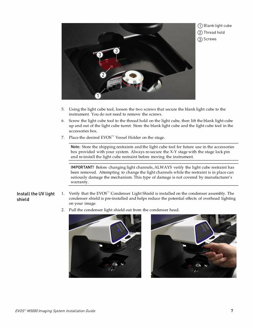
Install the UV light shield
1. Verify that the EVOS™ Condenser Light Shield is installed on the condenser assembly. The condenser shield is pre-installed and helps reduce the potential effects of overhead lighting on your image.
2. Pull the condenser light shield out from the condenser head.

8 EVOS™ M5000 Imaging System Installation Guide
] 3. Secure the UV light shield mount to the top of the condenser light shield using the two screws supplied with the UV shield assembly (not the protruding screws on the mount).
4. Clip the condenser light shield with the attached UV light shield mount back onto the condenser head.
5. Peel the protective paper from the UV light shield, then slide the orange UV light shield over the two protruding screws on light shield mount to attach it to the instrument.
Note: The UV light shield is provided as a safety feature and should be installed whenever the unit is in operation. The UV light shield is removable for access to the condenser sliders used in transmitted light mode. Simply unhook it from the screws on the UV light shield mount.
Connect the instrument
1. Confirm that the power switch is OFF (located on the back; see page 4).
2. Connect the USB receiver for the wireless mouse and keyboard to an available USB-A 2.0 port (located on the back; see page 4).
3. Connect the power adapter and power cord. Ensure a tight connection
4. Plug the power adapter into the power input port on the instrument (see page 4).
5. Plug the power cord into a power outlet and check for the light on the power supply.

EVOS™ M5000 Imaging System Installation Guide 9
Power ON the EVOS™ M5000 Imaging System
1. Turn the instrument power switch (located on the back; see page 4) to the ON position.
2. When the Capture tab is displayed, the EVOS™ M5000 Imaging System is ready to use.
IMPORTANT! You must remove all shipping restraints before you power on the EVOS™ M5000
Imaging System to prevent damage (page 6).

thermofisher.com/support | thermofisher.com/askaquestion
thermofisher.com
08 January 2019
Related documentation and support Related documentation
The publication numbers in this section are for the latest product versions available at the time of publication. For documentation supporting newer product versions, go to thermofisher.com/support.
Document Pub. No.
EVOS™ M5000 Imaging System User Guide MAN0017563
EVOS™ M5000 Imaging System Quick Reference MAN0017765 Customer and technical support
Visit thermofisher.com/support for the latest in services and support, including:
• Worldwide contact telephone numbers
• Product support, including:
- Product FAQs
- Software, patches, and updates
- Training for many applications and instruments
• Order and web support
• Product documentation, including user guides, manuals, and protocols Limited product warranty
Life Technologies Corporation and/or its affiliate(s) warrant their products as set forth in the Life Technologies’ General Terms and Conditions of Sale found on Life Technologies’ website at www.thermofisher.com/us/en/home/global/terms-and-conditions.html. If you have any questions, please contact Life Technologies at www.thermofisher.com/support.
Manufacturer: Life Technologies Corporation | 22025 20TH Ave SE | Bothell, WA 98021
The information in this document is subject to change without notice.
DISCLAIMER: TO THE EXTENT ALLOWED BY LAW, THERMO FISHER SCIENTIFIC AND/OR ITS AFFILIATE(S) WILL NOT BE LIABLE FOR SPECIAL, INCIDENTAL, INDIRECT, PUNITIVE, MULTIPLE OR CONSEQUENTIAL DAMAGES IN CONNECTION WITH OR ARISING FROM THIS DOCUMENT, INCLUDING YOUR USE OF IT.
Revision history: MAN0017783
Revision Date Description
B.0 08 January 2019 Update Capture screen.
A.0 07 August 2018 New installation guide for the EVOS™ M5000 Imaging System.
Trademarks: All trademarks are the property of Thermo Fisher Scientific and its subsidiaries unless otherwise specified.
© 2019 Thermo Fisher Scientific Inc. All rights reserved.