Evolution of Mount Fuji, Japan: Inference from drilling … Article Evolution of Mount Fuji, Japan:...
19
Research Article Evolution of Mount Fuji, Japan: Inference from drilling into the subaerial oldest volcano, pre-KomitakeMITSUHIRO YOSHIMOTO, 1 *TOSHITSUGU FUJII, 2 TAKAYUKI KANEKO, 2 ATSUSHI YASUDA, 2 SETSUYA NAKADA 2 AND AKIKAZU MATSUMOTO 3 1 Department of Natural History Sciences, Faculty of Science, Hokkaido University, N10 W8, Kita-ku, Sapporo, 060-0810, Japan (email: [email protected]), 2 Earthquake Research Institute, University of Tokyo, 1-1-1 Yayoi, Bunkyo-ku, Tokyo 113-0032, Japan, and 3 Geological Survey of Japan, National Institute of Advanced Industrial Science and Technology, Tsukuba Central 7, 1-1, Higashi 1-Chome, Tsukuba, Ibaraki 305-8567, Japan Abstract A buried, old volcanic body (pre-Komitake Volcano) was discovered during drill- ing into the northeastern flank of Mount Fuji. The pre-Komitake Volcano is characterized by hornblende-bearing andesite and dacite, in contrast to the porphyritic basaltic rocks of Komitake Volcano and to the olivine-bearing basaltic rocks of Fuji Volcano. K-Ar age determinations and geological analysis of drilling cores suggest that the pre-Komitake Volcano began with effusion of basaltic lava flows around 260 ka and ended with explosive eruptions of basaltic andesite and dacite magma around 160 ka. After deposition of a thin soil layer on the pre-Komitake volcanic rocks, successive effusions of lava flows occurred at Komitake Volcano until 100ka. Explosive eruptions of Fuji Volcano followed shortly after the activity of Komitake. The long-term eruption rate of about 3 km 3 /ka or more for Fuji Volcano is much higher than that estimated for pre-Komitake and Komitake. The chemical variation within Fuji Volcano, represented by an increase in incompatible elements at nearly constant SiO 2 , differs from that within pre-Komitake and other volcanoes in the northern Izu-Bonin arc, where incompatible elements increase with increasing SiO 2 . These changes in the volcanism in Mount Fuji may have occurred due to a change in regional tectonics around 150 ka, although this remains unproven. Key words: basalt, drilling core, eruptive history, Fuji Volcano, hornblende dacite, Komi- take Volcano, pre-Komitake Volcano. INTRODUCTION Mount Fuji is situated in a complex tectonic setting near the junction of three plates (North American Plate in the east, Eurasian (or Amur) Plate in the west, and Philippine Sea Plate in the south), under two of which the Pacific Plate subducts from east to west (Fig. 1a). It is one of the largest stratovolca- noes in the Japan arc with high, long-term erup- tion rates (5 km 3 /ka), as compared with typical subduction-related volcanoes (0.1–0.01 km 3 /ka; Tsukui et al. 1986). Fuji Volcano, the youngest part of Mount Fuji, has grown since about 100 ka through dominant eruptions of basaltic lava flows and tephra. The geochemistry is characterized by a wide variation of incompatible elements with little change in SiO 2 . It differs from other volca- noes of the northern Izu-Bonin arc (Fig. 1), which show a coupled variation between incompatible elements and SiO 2 (Tsuya 1971; Fujii 2001). The unique chemical characteristics of Fuji Volcano have been discussed in relation to its tec- tonic setting by several investigators (e.g. Arculus et al. 1991; Takahashi 2000; Fujii 2007). Fujii (2007) proposed that the chemical variations were formed by fractional crystallization of a hydrous magma in a deep magma chamber. That is, in hydrous basalt magma at high pressures, pyroxenes become the *Correspondence. Received 25 April 2009; accepted for publication 23 April 2010. Island Arc (2010) 19, 470–488 © 2010 Blackwell Publishing Asia Pty Ltd doi:10.1111/j.1440-1738.2010.00722.x
Transcript of Evolution of Mount Fuji, Japan: Inference from drilling … Article Evolution of Mount Fuji, Japan:...

Research ArticleEvolution of Mount Fuji, Japan: Inference from drilling into the
subaerial oldest volcano, pre-Komitakeiar_722 470..488
MITSUHIRO YOSHIMOTO,1* TOSHITSUGU FUJII,2 TAKAYUKI KANEKO,2 ATSUSHI YASUDA,2
SETSUYA NAKADA2 AND AKIKAZU MATSUMOTO3
1Department of Natural History Sciences, Faculty of Science, Hokkaido University, N10 W8, Kita-ku, Sapporo,060-0810, Japan (email: [email protected]), 2Earthquake Research Institute, University of Tokyo,
1-1-1 Yayoi, Bunkyo-ku, Tokyo 113-0032, Japan, and 3Geological Survey of Japan, National Institute of AdvancedIndustrial Science and Technology, Tsukuba Central 7, 1-1, Higashi 1-Chome, Tsukuba, Ibaraki 305-8567, Japan
Abstract A buried, old volcanic body (pre-Komitake Volcano) was discovered during drill-ing into the northeastern flank of Mount Fuji. The pre-Komitake Volcano is characterizedby hornblende-bearing andesite and dacite, in contrast to the porphyritic basaltic rocks ofKomitake Volcano and to the olivine-bearing basaltic rocks of Fuji Volcano. K-Ar agedeterminations and geological analysis of drilling cores suggest that the pre-KomitakeVolcano began with effusion of basaltic lava flows around 260 ka and ended with explosiveeruptions of basaltic andesite and dacite magma around 160 ka. After deposition of a thinsoil layer on the pre-Komitake volcanic rocks, successive effusions of lava flows occurred atKomitake Volcano until 100 ka. Explosive eruptions of Fuji Volcano followed shortly afterthe activity of Komitake. The long-term eruption rate of about 3 km3/ka or more for FujiVolcano is much higher than that estimated for pre-Komitake and Komitake. The chemicalvariation within Fuji Volcano, represented by an increase in incompatible elements atnearly constant SiO2, differs from that within pre-Komitake and other volcanoes in thenorthern Izu-Bonin arc, where incompatible elements increase with increasing SiO2. Thesechanges in the volcanism in Mount Fuji may have occurred due to a change in regionaltectonics around 150 ka, although this remains unproven.
Key words: basalt, drilling core, eruptive history, Fuji Volcano, hornblende dacite, Komi-take Volcano, pre-Komitake Volcano.
INTRODUCTION
Mount Fuji is situated in a complex tectonic settingnear the junction of three plates (North AmericanPlate in the east, Eurasian (or Amur) Plate in thewest, and Philippine Sea Plate in the south), undertwo of which the Pacific Plate subducts from east towest (Fig. 1a). It is one of the largest stratovolca-noes in the Japan arc with high, long-term erup-tion rates (5 km3/ka), as compared with typicalsubduction-related volcanoes (0.1–0.01 km3/ka;Tsukui et al. 1986). Fuji Volcano, the youngest part
of Mount Fuji, has grown since about 100 kathrough dominant eruptions of basaltic lava flowsand tephra. The geochemistry is characterized bya wide variation of incompatible elements withlittle change in SiO2. It differs from other volca-noes of the northern Izu-Bonin arc (Fig. 1), whichshow a coupled variation between incompatibleelements and SiO2 (Tsuya 1971; Fujii 2001).
The unique chemical characteristics of FujiVolcano have been discussed in relation to its tec-tonic setting by several investigators (e.g. Arculuset al. 1991; Takahashi 2000; Fujii 2007). Fujii (2007)proposed that the chemical variations were formedby fractional crystallization of a hydrous magma ina deep magma chamber. That is, in hydrous basaltmagma at high pressures, pyroxenes become the
*Correspondence.
Received 25 April 2009; accepted for publication 23 April 2010.
Island Arc (2010) 19, 470–488
© 2010 Blackwell Publishing Asia Pty Ltd doi:10.1111/j.1440-1738.2010.00722.x
Mie
ハイライト表示
Mie
ハイライト表示

major phase to crystallize, instead of olivine andplagioclase. He proposed that the Fuji Volcanomagma chamber is located at a depth of 15–25 km,based both on petrology and on seismologicalinvestigations (Lees & Ukawa 1992; Ukawa 2005;Nakamichi et al. 2007). On the other hand, Taka-hashi (2007) proposed an upwelling of mantlematerial through a split within the subducted Phil-
ippine Sea Plate just beneath Mount Fuji, based oncurrent GPS measurements and on the absence ofearthquakes at the subducting slab surface underMount Fuji (Yamaoka 1995). However, the geom-etry of the subducted slab and seismological evi-dence (Seno 2005) do not support this proposal. Toexplore the tectonic background controlling thehigh eruption rate and chemical evolution of this
Fig. 1 Tectonic setting and location of Mount Fuji and drilling sites. (a) Tectonic setting of the study area. PHS, Philippine Sea Plate; EUR, Eurasian Plate;NAM, North American Plate; PAC, Pacific Plate. (b) Quaternary volcanoes around Mount Fuji. Solid circles are Higashi-Izu Monogenic volcanoes (c)Locations of drilling sites, ERI-FJ-1 to -5 of the Earthquake Research Institute (ERI), University of Tokyo. Maps, ‘Fujisan’ and ‘Subashiri’, published by theGeographical Survey Institute, Japan, were used. Dotted lines indicate a horseshoe-shaped crater.
Evolution of Mount Fuji 471
© 2010 Blackwell Publishing Asia Pty Ltd
Mie
ハイライト表示
Mie
ハイライト表示

volcano, detailed temporal, geologic and chemicalchanges in this volcano, including older volcanicactivity hidden by the younger edifice, need to beexamined, along with the relationships of the sur-rounding volcanoes.
Scientific drilling, a good way to investigate thetemporal, geological and chemical development ofMount Fuji in detail, was sponsored by the Minis-try of Education, Culture, Sports, Science andTechnology, Japan, and was carried out during2001–2003, soon after the occurrence of a spate ofdeep-seated, low frequency earthquakes. In thispaper, we describe lithological features, whole-rock chemistry and K-Ar ages of the drilled coresamples, aiming to provide new constraints on thevolcanological and geochemical evolution of MountFuji.
TECTONIC SETTING AND GEOLOGY OF THE FUJIVOLCANIC FIELD
Collision of the Philippine Sea Plate and the NorthAmerican Plate resulted in accretion of the uppercrust onto the North American Plate and subduc-tion of the lower crust beneath the North Ameri-can Plate (e.g. Seno 2005). The boundary betweenthe North American and Philippine Sea Platesjumped to the south periodically during repeatedaccretion episodes. The upper crust accreted fromthe Philippine Sea Plate forms the present IzuPeninsula. Mount Fuji is located just behind thepresent plate boundary, which runs from west ofAshitaka Volcano to the northeast of HakoneVolcano (Fig. 1b). Deep depressions suggestingpossible remnants of an older plate boundary arefound to the west and north of Mount Fuji (Amano1991).
Fuji Volcano has grown to cover a part of Ashi-taka Volcano in the south and most of KomitakeVolcano in the north (Tsuya 1971). Results fromdrilling on a saddle between Mount Fuji and Ashi-taka indicate that olivine basalt of Fuji Volcanocovers olivine-two-pyroxene andesite of AshitakaVolcano at about 200 m above sea level (a.s.l.)(Tsuya 1962). At present, Komitake Volcano isexposed on the north flank of Mount Fuji (Fig. 1c).These volcanoes had been active before the initialeruptions from Fuji Volcano at about 100 ka.
ASHITAKA VOLCANO
Ashitaka Volcano, located on the southeastern footof Mount Fuji, is a dissected stratovolcano. Its
activity initiated with eruption of basalt to basalticandesite lava flows and pyroclastics at around400 ka and ended with eruption of a hornblende-bearing dacite lava dome around 100 ka (Yui &Fujii 1989). Its rocks are within the range of thehigh-alumina basalt and pigeonitic rock series ofKuno (1968). The andesite and dacite fall withinthe calc-alkaline hypersthenic rock series.
KOMITAKE VOLCANO
The edifice of Komitake Volcano is exposed only ina horseshoe-shaped crater that opens to the north-east on the northern middle slope (about 2300 ma.s.l.) of Mount Fuji (Fig. 1). Lava flows, each0.3–1 m thick, are exposed inside the crater. Thecenter of Komitake Volcano, estimated from dipsof the lava flows, is 0.7 km east-northeast ofthe present peak of Komitake (Tsuya 1971). Itsrocks are plagioclase-phyric, olivine-bearing, two-pyroxene basalt and basaltic andesite with51–53 wt% SiO2 (Tsuya 1968). Its activity isbelieved to have started at the same time as Ashi-taka Volcano, in the middle-Pleistocene, based onthe similar extent of erosion of the two volcanoes(Tsuya 1971). Tsuya (1971) also considered Komi-take and Ashitaka volcanoes to be chemicallysimilar.
FUJI VOLCANO
Fuji Volcano consists of Older-Fuji and Younger-Fuji stages (Machida 1964; Tsuya 1971; Miyaji1988). Older-Fuji Volcano began its activity atabout 100 ka; a silicic tephra marker called ‘OnPm-I’ has been identified just below the lowestpart of the Older-Fuji ejecta (Machida 1964).Eruptions of Older-Fuji are thought to have beenexplosive owing to wide-spread basaltic air-falldeposits with a volume up to 250 km3 that coveredabroad area from the eastern flank of Mount Fujito the south Kanto Plain, including Tokyo (Miyajiet al. 1992). Mudflow deposits are plentifully dis-tributed on the eastern and western flanks ofMount Fuji (Machida 2007). These Older-Fujiejecta and the mudflow deposits are covered by theFuji black soil (FB), dated to 10-5 ka (Machida1964). Younger-Fuji Volcano has been active since20 ka with eruptions of basaltic lava flows (Miyaji1988; Yamamoto et al. 2005). Its volcanism is sub-divided into six stages with different eruptionstyles (Miyaji 1988). Dacite and andesite tephrawas formed during recent explosive activities, as
472 M. Yoshimoto et al.
© 2010 Blackwell Publishing Asia Pty Ltd
Mie
ハイライト表示

observed in the Hoei eruption (AD 1707) and theZunasawa eruption (c. 3 ka).
The dominant magma type for both Older- andYounger-Fuji volcanoes is high-alumina basalt (48–52 wt% SiO2), in which phenocrysts are mainlyplagioclase and olivine with a minor amount of cli-nopyroxene. Plagioclase-phyric basalt withoutolivine phenocrysts is rarely observed (Tsuya1971). The dacites contain orthopyroxene phenoc-rysts without hornblende.
CORE DESCRIPTION FROM DRILL HOLES INMOUNT FUJI
Drilling was conducted on the northern andeastern flanks of Mount Fuji at five sites (ERI-FJ-1 to -5) (Nakada et al. 2004) (Fig. 1, Table 1). Tomonitor the volcanic activity of Fuji Volcano,sensors were installed at the three sites (FJ-1 to-3) on the north to northeastern flank: seismo-meters (all three sites), strainmeter (FJ-2), andtiltmeter and thermometer (FJ-3). The other twosites, FJ-4 and -5, on the eastern flank, weredrilled to further understand the eruptive historyof Fuji Volcano. FJ-1 (1722.7 m a.s.l.) was drilled toa depth of 100 m. FJ-2 (1441.8 m a.s.l.) consists oftwo holes 100 m and 414 m in depth. Geophysicallogging, consisting of normal resistivity, spontane-ous potential, acoustic, density, neutron, seismicvelocity, natural gamma ray, temperature, FullboreFormation MicroImager (FMI, microresistivityformation images) and borehole caliper, wascarried out in both holes for depth intervals of1–100 m and 75–414 m, respectively. FJ-3(1406.7 m a.s.l.) consists of three holes 129 m,365 m and 650 m in depth. Geophysical logging wascarried out for depth intervals 0–129 m, 115–365 mand 352–650 m, respectively. FJ-4 (997.2 m a.s.l.)and FJ-5 (1487 m a.s.l.) were drilled to 75 m and200 m, respectively. Core samples from shallowerdepths were obtained using a core pack samplerwith a thin plastic tube, and those from deeperdepths were obtained using an HQ size (core diam-eter of 61 mm) core barrel (Nakada et al. 2004)(Table 1). Diameters of the recovered core samplesrange from 61 to 70 mm. Total core recovery wasmore than 94%.
We describe herein characteristics of rocks anddeposits observed in drillholes FJ-1 to FJ-3. FJ-4and FJ-5 are not described since they are com-posed of only younger rocks (Fig. 2). Photographsof core samples with typical lithofacies are shown Tabl
e1
Loc
atio
n,dr
illin
gde
pth
and
core
dra
nge
ofth
ebo
reho
les
inM
ount
Fuj
i
Site
Lat
itud
eL
ongt
itud
eE
leva
tion
(m)
Hol
eD
rilli
ngde
pth
(m)
Cor
edra
nge
(m)
Met
hod
(m)
ER
I-F
J-1
35°2
3′42
″N13
8°45
′58″
E17
22.7
FJ-
110
00–
100
W:0
–27
C:2
7–10
0E
RI-
FJ-
235
°24′
40″N
138°
44′5
9″E
1441
.8F
J-2
100
0–10
0C
FJ-
2A41
475
–414
C:8
9–20
0W
:75–
89,2
00–4
14E
RI-
FJ-
335
°24′
36″N
138°
46′3
8″E
1406
.7F
J-3
129
0–12
9C
FJ-
3B36
511
5–36
5C
FJ-
3C65
035
2–65
0W
ER
I-F
J-4
35°2
5′10
″N13
8°50
′55″
E99
7.2
FJ-
475
0–75
CE
RI-
FJ-
535
°22′
04″N
138°
48′0
0″E
1487
FJ-
520
00–
200
C
C,u
sing
aco
repa
cksa
mpl
erw
ith
ath
inpl
asti
ctu
be;W
,usi
ngan
HQ
size
(cor
edi
amet
erof
61m
m)
trip
letu
bew
irel
ine
core
barr
el.
Evolution of Mount Fuji 473
© 2010 Blackwell Publishing Asia Pty Ltd

in Figure 3. Core depths (m) for lavas given in thetext indicate those at the top of flows.
ERI-FJ-1 (FJ-1)
FJ-1 is composed of lava flows, mudflow depositsand unspecified deposits, lacking both soil layersand layers of well sorted and monolithologic
angular scoria, classified as air-fall deposit(Fig. 2). Five lavas are observed, each with amassive center and fractured upper and lowermargins, sometimes reddish in color due tooxidation. Rocks are basalt with about 15 vol.%plagioclase, olivine, clinopyroxene and rare ortho-pyroxene phenocrysts. Mudflow deposits aresubdivided into two types: a moderately sorted
Fig. 2 Lithostratigraphy of the boreholes (ERI-FJ-1 to -5). The locations of the drilling sites are indicated in Figure 1.
474 M. Yoshimoto et al.
© 2010 Blackwell Publishing Asia Pty Ltd

scoriaceous one and a poorly sorted polymicticone. The former consists of rounded scoriawithout fine ash, and resembles a deposit from amixture of snow and scoria commonly observedduring seasons of snow melting at Mount Fuji(Anma 2007). The latter contains abundant lava
clasts up to 10 cm across and fine ash particles inthe matrix. The unspecified deposits consisting ofwell-sorted clasts of lava and scoria are eitherfragmented clinker from lava flows or coarseclasts of mudflows, in which fine particles werewashed out during the drilling operation.
Fig. 3 Photographs of recovered drilling cores from ERI-FJ-2 and -3, showing typical occurrences for ERI-FJ-1 to -3. (a) Scoriaceous mudflow (slushflow) deposit from 25 to 30 m depth of the FJ-3. (b) Basaltic lava flow, orthopyroxene-bearing olivine basalt with 15 vol.% phenocrysts and an underlyingburned red scoria fall deposit from 90 to 95 m in FJ-2. (c) Plagioclase-phyric (35 vol.%) basaltic andesite lava flows and alternation of scoria fall depositsand weathered ashy soils from 170 to 175 m in FJ-2. (d) Hornblende dacite lava clasts, which are bluish-gray in color and less than 12 cm long, andtwo-pyroxene andesite and basaltic andesite in the mudflow deposit from 185 to 190 m in FJ-2. (e) Andesitic pyroclastic flow deposit from 190 to 195 min FJ-2. (f) Massive basaltic andesite lava flow with about 30 vol.% phenocrysts consisting mainly of plagioclase and a small amount of clinopyroxene,orthopyroxene and olivine from 215 to 220 m in FJ-2. (g) Typical polymict mudflow deposit from cores at 405 to 410 m in FJ-2. The mudflow is composedof large blocks of lava in a fine-grained matrix of volcanic material.
Evolution of Mount Fuji 475
© 2010 Blackwell Publishing Asia Pty Ltd
ERI-FJ-2 (FJ-2)
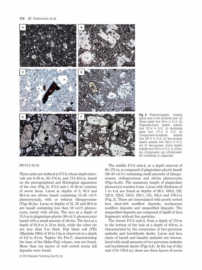
Three units are defined in FJ-2, whose depth inter-vals are 0–95 m, 95–174 m, and 174–414 m, basedon the petrographical and lithological signaturesof the core (Fig. 2). FJ-2 unit-1 (0–95 m) consistsof seven lavas. Lavas at depths of 5, 61.9 and90.4 m are olivine basalt containing 15–25 vol.%phenocrystals, with or without clinopyroxene(Figs 3b,4a). Lavas at depths of 21, 25 and 26.8 mare basalt containing less than 10 vol.% phenoc-rysts, rarely with olivine. The lava at a depth of15.5 m is plagioclase-phyric (30 vol.% phenocrysts)basalt with a small amount of olivine. The lava at adepth of 61.9 m is 13 m thick, while the other sixare less than 3 m thick. Fuji black soil (FB)(Machida 1964) of 10 to 5 ka is observed at a depthof 9.2 to 9.3 m. Tephra ‘On Pm-I’, characterizingthe base of the Older-Fuji volcano, was not found.More than ten layers of well sorted scoria falldeposits were found.
The middle FJ-2 unit-2, at a depth interval of95–174 m, is composed of plagioclase-phyric basalt(30–35 vol.%) containing small amounts of clinopy-roxene, orthopyroxene and olivine phenocrysts(Figs 3c,4b). The maximum length of plagioclasephenocryst reaches 3 mm. Lavas with thickness of1 to 4 m are found at depths of 98.5, 103.8, 122,125.9, 129.8, 134.8, 139.1, 155, 165.4 and 170.5 m(Fig. 2). These are intercalated with poorly sortedlava clast-rich mudflow deposits, scoriaceousmudflow deposits and unspecified deposits. Theunspecified deposits are composed of lapilli of lavafragments without fine particles.
The lowest FJ-2 unit-3, from a depth of 174 mto the bottom of the hole at a depth of 410 m, ischaracterized by the occurrence of two-pyroxeneandesite and hornblende dacite. Lavas and lavaclasts of basalt and basaltic andesite are interca-lated with small amounts of two-pyroxene andesiteand hornblende dacite (Figs 3,4). At the top of thisunit (174–176.6 m), there are three layers of scoria
Fig. 4 Photomicrographs showingtypical rocks in the recovered cores: (a)Olivine basalt from 64 m in FJ-2; (b)Plagioclase-phyric basaltic andesitefrom 131 m in FJ-2; (c) Hornblendedacite from 177 m in FJ-2; (d)Clinopyroxene-hornblende andesitefrom 447 m in FJ-3; (e) Two-pyroxenebasaltic andesite from 355 m in FJ-3;and (f) Two-pyroxene olivine basalticandesite from 376 m in FJ-2. ol, olivine;cpx, clinopyroxene; opx, orthopyroxene;hbl, hornblende; pl, plagioclase.
476 M. Yoshimoto et al.
© 2010 Blackwell Publishing Asia Pty Ltd
fall deposits separated by soil layers (Fig. 3c). Atdepths of 176.6–190 m, a poorly sorted mudflowdeposit includes clasts of hornblende dacite, andtwo-pyroxene andesite and basaltic andesite(Fig. 3d). Some of the basaltic andesite here ischaracterized by large phenocrysts of pyroxene.At depths of 190–201 m, two layers of very poorlysorted and monolithologic pyroclastic flow depositsof two-pyroxenes andesite are found, the bottomsof which are oxidized (Fig. 3e). The lowest section(at a depth interval of 201 m to 414 m) consists ofnine lavas and several polymict mudflow deposits.The latter contain large, massive blocks up to100 cm across (Fig. 3g). Lavas and most clasts inthe mudflow deposits are plagioclase-phyric olivinebasalt and basaltic andesite, with or without cli-nopyroxene, and orthopyroxene basaltic andesite,with or without olivine and/or clinopyroxene,both of which contain 25–40 vol.% phenocrysts.Lavas at depths of 210 m, composed of olivine-two-pyroxene basaltic andesite, and 350 m, composedof clinopyroxene-bearing olivine basalt, are 17 mand 10 m thick, respectively. Oxidized, reddishscoria fall deposits more than 1 m thick lie beneaththese lavas (Fig. 3f). The other lavas at depths of202.5, 338, 365.7, 375, 378, 388.8 and 393.6 m areless than 2 m thick.
ERI-FJ-3 (FJ-3)
FJ-3 is composed mainly of mudflow depositsintercalated with six lavas and scoria fall layers.Three different units are also recognized in FJ-3 atdepths of 0–75 m, 75–315 m, and 315–650 m, basedon the occurrence of mudflow deposits and the pet-rographical features of rocks (Fig. 2). Althoughdeposits at depths of 315–328 m were grouped intothe upper unit of FJ-3 by Nakada et al. (2007), theyare regrouped petrographically into FJ-3 unit-3.FJ-3 unit-1 (at depth interval of 0–75 m) and unit-3(at depth interval of 315–650 m) are similar inlithofacies to those of FJ-2 units-1 and -3, respec-tively; however, FJ-3 unit-2 (at depth interval of75–315 m) differs from FJ-2 unit-2 both petro-graphically and lithologically.
FJ-3 unit-1 is composed of two lavas, twentyscoria-fall deposits and a pyroclastic flow deposit,separated by weathered soil layers and moder-ately sorted scoriaceous mudflow deposits. Thepyroclastic flow deposit found at depths of 8–9 mconsists of poorly sorted basaltic scoria and fineash, and contains charcoals. Fuji black soil (FB) isobserved at depths of 14.2–14.7 m. Lavas at depths
of 31.8 and 56 m are olivine basalt with 15–25 vol.%phenocrysts.
FJ-3 unit-2, at a depth interval of 75–315 m, isalmost entirely composed of moderately to poorlysorted scoriaceous mudflow deposits, which differfrom FJ-2 unit-2 petrographically and lithologi-cally. The mudflow deposits occasionally containlava clasts up to 10 cm across, which are similarto rocks of FJ-2 units-1 and -3 without horn-blende. Plagioclase-phyric basaltic andesite, char-acterizing FJ-2 unit-2, was merely found as aclast in a mudflow deposit at a depth of 225.5 m.Lavas of olivine basalt, containing 10–12 vol.%phenocrysts with a small amount of pyroxenes,are observed at depths of 209.8 and 213 m. Atdepths of 243–245 m, thin well-sorted scoria-falldeposits with brown-colored weathered layers areobserved.
FJ-3 unit-3 at a depth interval of 315–650 mis mainly composed of poorly sorted polymicmudflow deposits and two massive lavas. The topof this unit, at depths of 315–328.5 m, consistsof alternating layers of well-sorted scoria andbrown-colored, weathered soil with a thickness ofabout 4 m. More than ten scoria fall deposits arepresent at this depth interval. One of them, ata depth of 327 m, contains hornblende-bearingscoria. Massive lava flow (25 m thick) ofhornblende-two-pyroxene basaltic andesite withmore than 40 vol.% phenocrysts is found at adepth of 390 m. Olivine-bearing two-pyroxenebasaltic andesite (4 m thick) with more than 40vol.% phenocrysts is found at a depth of 584.4 m.Most clasts in a mudflow deposit below the depthof 328.5 m are two-pyroxene basaltic andesite andandesite with or without olivine phenocrysts.Many of them are characterized by large (2 to4 mm long) clinopyroxene phenocrysts (Fig. 4e),similar to the two-pyroxene basaltic andesite andandesite from FJ-2 unit-3. Some andesitic clastsalso contain hornblende phenocrysts (Figs 2,4d).Thus, FJ-3 unit-3 has common signatures withFJ-2 unit-3.
Two types of mudflow deposits are recognized inboth FJ-2 and -3 (Fig. 3a,g): scoriaceous mudflowsand polymict mudflows containing abundant largelava clasts. A scoriaceous mudflow deposit is mod-erately sorted and is mainly composed of lapilli andcoarse ash particles of basaltic scoria. It commonlylacks fine-ash particles, although it occasionallycontains lava clasts up to 10 cm in length. On theother hand, a polymict mudflow deposit is verypoorly sorted, and contains abundant fine ash
Evolution of Mount Fuji 477
© 2010 Blackwell Publishing Asia Pty Ltd

particles in the matrix. It also contains about 20%block-sized clasts of basalt, andesite and dacite.The two types of mudflow deposits are separatedby layers of scoria fall and brown weathered soil atthe depths of 174–176.7 m in FJ-2 and 315–328.5 min FJ-3 (Fig. 2). The lithological difference be-tween the two types of mudflow deposits reflects adifference in source materials; one is dominantlyscoria-rich tephra, while the other is rich in basalt,andesite and dacite lava flows with subordinatepyroclastic materials.
WHOLE ROCK CHEMISTRY
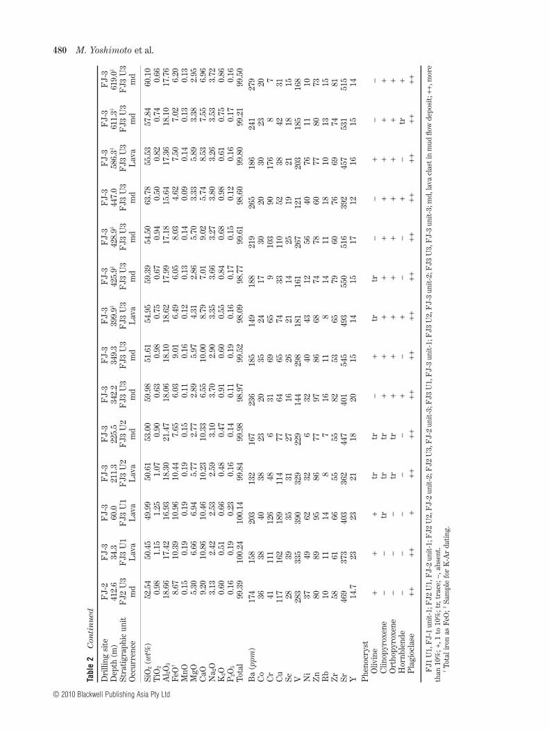
Major and trace elements of lavas and the lavaclasts in mudflow deposits from the drill coreswere measured using an X-ray fluorescence spec-trometer, Philips PW 2400 (Philips, Almelo, theNetherlands) of Earthquake Research Institute,University of Tokyo. Fifty-two samples from 37lavas and 190 lava clasts from mudflow depositswere selected. The lava clasts were collectedthroughout mudflow deposits as evenly as possibleand represent about 20–30% of all clasts largerthan 10 cm in length. Representative analyses ofcore samples are listed in Table 2. Variationdiagrams of the analyzed samples are shown inFigures 5 and 6.
Whole rock chemistry of the core samples fallsinto three groups, corresponding to the strati-graphically defined units of FJ-2 units-1 to -3(Table 3). These groups are clearly distinguishedon variation diagrams of MgO vs. SiO2, and TiO2 vs.MgO (Figs 5,6) and in the stratigraphic plot(Fig. 7). Rocks of Group 1 found in FJ-2 unit-1 andGroup 2 found in FJ-2 unit-2 show a remarkablynarrow range in SiO2 (49 to 53 wt%). In contrast,rocks of Group 3, found in FJ-2 unit-3 range from50 to 70 wt% in SiO2. Although rocks from the FJ-2units-1 and -2 are similar in SiO2, they are distinctin other elements. For example, FJ-2 unit-2 rocksare higher in Al2O3 and lower in TiO2, FeO, MgO,K2O, P2O5, Ba, Co, Cr, Ni, Zn, Y, and Rb than FJ-2unit-1. Rocks of FJ-2 unit-3 show chemical trendsthat differ from those of FJ-2 units-1 and -2; thatis, Na2O, K2O, Ba, Zr, and Rb increase with increas-ing SiO2, whereas TiO2, Al2O3, FeO, MnO, MgO,CaO, Co, V, Sc, and Y decrease. Basalt and basalticandesite from FJ-2 unit-3 have lower TiO2, K2Oand P2O5 and higher Al2O3 than those from FJ-2unit-1. Rocks in FJ-2 units-2 and -3 can be dis-criminated in the variation diagrams of MgO vs.SiO2 and TiO2 vs. MgO.
Rocks of FJ-1 and two lavas from FJ-3 unit-1are similar in chemistry to those from Group 1.Samples from FJ-3 unit-3 range from 50 to 63 wt%SiO2 and show the same compositional variation asGroup 3. On the other hand, samples from lavasand lava clasts in mudflow deposits from FJ-3unit-2 do not show chemical characteristics similarto Group 2, though they have compositions that fallinto Groups 1 and 3; they are low in K2O and havea narrow range of TiO2. Only one sample fromFJ-3 unit-2 with plagioclase-phyric texture at225.5 m plots near the compositional range ofGroup 2.
Samples below 285 m in depth of FJ-2 arebasalt and basaltic andesite, having narrowranges in SiO2 and the other major elements. Incontrast, samples from the upper part of FJ-2unit-3, 174–285 m deep, show a wide range inSiO2; SiO2 increases with decreasing depth frombasalt to dacite. At depths from 95 to 174 m inFJ-2, major elements, including SiO2, remainnearly constant. Finally, above 95 m in FJ-2unit-1, SiO2 remains in a narrow range, thoughthe other elements vary widely and unsystemati-cally. On the other hand, almost all major ele-ments in the FJ-3 samples below 75 m graduallyincrease or decrease with depth except K2O,which shows an abrupt jump across the boundarybetween units-2 and -3.
K-Ar AGE DETERMINATIONS
K-Ar age determinations were carried out atGeological Survey of Japan, National Instituteof Advanced Industrial Science and Technology(AIST). Six rock samples were collected from lavaflows and mudflow deposits in the deeper part ofFJ-3. The samples were crushed using an ironpestle and sieved to 0.25–0.50 mm in diameter.Phenocrysts were removed as much as possibleusing an isodynamic separator. The groundmass-rich fractions were prepared for argon isotopeanalyses, and the rest of samples were further pul-verized for potassium analyses using an agatemortar.
The concentrations of potassium were deter-mined by flame emission spectrometry, in whichpeak integration and lithium internal standardmethods were adopted (Matsumoto 1989). Theconcentrations of radiogenic 40Ar were determinedon a VG Isotopes 1200C mass spectrometer by theconventional isotope dilution method using a 38Ar
478 M. Yoshimoto et al.
© 2010 Blackwell Publishing Asia Pty Ltd

Tabl
e2
Rep
rese
ntat
ive
maj
oran
dtr
ace
elem
ent
com
posi
tion
san
dm
iner
alas
sem
blag
esfo
rco
resa
mpl
es
Dri
lling
site
FJ-
1F
J-1
FJ-
2F
J-2
FJ-
2F
J-2
FJ-
2F
J-2
FJ-
2F
J-2
FJ-
2F
J-2
FJ-
2F
J-2
Dep
th(m
)45
.075
.65.
517
.125
.627
.564
.199
.915
6.4
177.
520
0.2
214.
933
8.1
393.
0St
rati
grap
hic
unit
FJ1
U1
FJ1
U1
FJ2
U1
FJ2
U1
FJ2
U1
FJ2
U1
FJ2
U1
FJ2
U2
FJ2
U2
FJ2
U3
FJ2
U3
FJ2
U3
FJ2
U3
FJ2
U3
Occ
urre
nce
Lav
aL
ava
Lav
aL
ava
Lav
aL
ava
Lav
aL
ava
Lav
am
dm
dL
ava
Lav
aL
ava
SiO
2(w
t%)
51.7
351
.43
51.4
651
.48
51.4
850
.76
51.8
450
.85
50.7
069
.50
61.4
454
.19
50.9
852
.88
TiO
21.
291.
141.
241.
431.
811.
931.
251.
021.
070.
310.
650.
960.
960.
96A
l 2O3
16.8
016
.63
17.3
019
.16
16.4
015
.85
16.9
520
.23
19.0
616
.30
17.2
018
.83
18.0
419
.16
FeO
†10
.54
10.4
610
.42
9.62
12.0
713
.14
10.3
49.
409.
872.
605.
408.
8710
.29
8.77
MnO
0.18
0.18
0.18
0.16
0.20
0.21
0.17
0.16
0.18
0.18
0.11
0.18
0.18
0.15
MgO
6.06
6.87
5.90
3.87
4.50
4.87
6.03
3.90
4.04
0.78
3.08
3.81
6.35
4.47
CaO
10.0
610
.20
10.0
510
.17
9.05
8.91
10.1
410
.44
10.0
13.
796.
488.
839.
769.
12N
a 2O
2.70
2.48
2.55
3.03
3.03
2.93
2.71
2.66
2.73
4.85
3.91
3.24
2.63
3.13
K2O
0.67
0.60
0.71
0.82
0.98
1.00
0.66
0.35
0.42
1.06
0.89
0.49
0.45
0.59
P2O
50.
230.
190.
250.
320.
370.
380.
230.
130.
140.
130.
150.
170.
140.
16To
tal
100.
2610
0.18
100.
0610
0.06
99.8
999
.98
100.
3299
.14
98.2
299
.50
99.3
199
.57
99.7
899
.39
Ba
(ppm
)19
818
820
726
729
429
621
615
513
131
225
318
613
617
0C
o38
4136
3035
4038
3029
320
2441
31C
r11
117
572
3926
1911
012
6-
464
4821
Cu
203
160
167
204
274
273
168
134
903
3528
7510
6Sc
3636
3729
3636
3332
304
1522
3225
V37
433
534
932
343
049
036
533
632
67
149
208
318
260
Ni
5575
4032
3132
5310
9-
346
3923
Zn
9793
9595
120
129
9682
8482
6582
8580
Rb
1313
1517
2121
145
717
158
710
Zr
7766
8110
010
911
276
5053
110
8058
4760
Sr39
133
138
843
740
438
539
942
339
940
646
749
137
646
6Y
2322
2527
3335
2217
1918
1318
1718
Phe
nocr
yst
Oliv
ine
++
+tr
tr-
++
+-
-+
++
Clin
opyr
oxen
e-
tr+
--
-+
--
-+
+tr
-O
rtho
pyro
xene
-tr
--
--
-tr
tr-
++
-+
Hor
nble
nde
--
--
--
--
-+
--
--
Pla
gioc
lase
++
++++
++
+++
+++
++++
++++
Evolution of Mount Fuji 479
© 2010 Blackwell Publishing Asia Pty Ltd
Tabl
e2
Con
tin
ued
Dri
lling
site
FJ-
2F
J-3
FJ-
3F
J-3
FJ-
3F
J-3
FJ-
3F
J-3
FJ-
3F
J-3
FJ-
3F
J-3
FJ-
3F
J-3
Dep
th(m
)41
2.6
34.3
60.0
211.
322
5.5
342.
234
9.3
399.
9‡42
5.9‡
428.
9‡44
7.0
586.
3‡61
1.3‡
619.
0‡
Stra
tigr
aphi
cun
itF
J2U
3F
J3U
1F
J3U
1F
J3U
2F
J3U
2F
J3U
3F
J3U
3F
J3U
3F
J3U
3F
J3U
3F
J3U
3F
J3U
3F
J3U
3F
J3U
3O
ccur
renc
em
dL
ava
Lav
aL
ava
md
md
md
Lav
am
dm
dm
dL
ava
md
md
SiO
2(w
t%)
52.5
450
.45
49.9
950
.61
53.0
059
.98
51.6
154
.95
59.3
954
.50
63.7
855
.53
57.8
460
.10
TiO
20.
981.
151.
251.
070.
900.
630.
980.
750.
670.
940.
500.
820.
740.
66A
l 2O3
18.6
617
.42
16.9
318
.30
21.4
718
.06
18.1
018
.62
17.9
917
.18
15.6
417
.36
18.1
017
.76
FeO
†8.
6710
.39
10.9
610
.44
7.65
6.03
9.01
6.49
6.05
8.03
4.62
7.50
7.02
6.20
MnO
0.15
0.19
0.19
0.19
0.15
0.11
0.16
0.12
0.13
0.14
0.09
0.14
0.13
0.13
MgO
5.30
6.66
6.94
5.77
2.77
2.89
5.97
4.31
2.86
5.70
3.33
5.89
3.38
2.95
CaO
9.20
10.8
610
.46
10.2
310
.33
6.55
10.0
08.
797.
019.
025.
748.
537.
556.
96N
a 2O
3.13
2.42
2.53
2.59
3.10
3.70
2.90
3.35
3.66
3.27
3.80
3.26
3.53
3.72
K2O
0.60
0.51
0.66
0.48
0.47
0.91
0.60
0.55
0.84
0.68
0.98
0.61
0.75
0.86
P2O
50.
160.
190.
230.
160.
140.
110.
190.
160.
170.
150.
120.
160.
170.
16To
tal
99.3
910
0.24
100.
1499
.84
99.9
898
.97
99.5
298
.09
98.7
799
.61
98.6
099
.80
99.2
199
.50
Ba
(ppm
)17
415
820
313
216
723
618
514
918
821
926
518
624
127
9C
o36
3840
3823
2035
2417
3020
3023
20C
r41
111
126
486
3169
659
103
9017
68
7C
u11
716
218
911
477
6465
7433
110
5238
4231
Sc28
3935
3127
1626
2114
2519
2118
15V
283
335
390
329
229
144
298
181
161
267
121
203
185
168
Ni
3749
6232
632
4043
1256
4076
1110
Zn
8089
9586
7797
8668
7478
6077
8073
Rb
1011
148
716
118
1411
1810
1315
Zr
5861
6655
5582
5365
7960
7669
7481
Sr46
937
340
336
244
740
154
549
355
051
639
245
753
151
5Y
14.7
2323
2118
2015
1415
1712
1615
14P
heno
crys
tO
livin
e+
++
trtr
-+
trtr
--
+-
-C
linop
yrox
ene
--
trtr
tr+
++
++
++
++
Ort
hopy
roxe
ne-
--
trtr
++
++
++
++
+H
ornb
lend
e-
--
--
+-
+-
-+
-tr
+P
lagi
ocla
se++
+++
++++
++++
++++
++++
++++
++
FJ1
U1,
FJ-
1un
it-1
;FJ2
U1,
FJ-
2un
it-1
;FJ2
U2,
FJ-
2un
it-2
;FJ2
U3,
FJ-
2un
it-3
;FJ3
U1,
FJ-
3un
it-1
;FJ3
U2,
FJ-
3un
it-2
;FJ3
U3,
FJ-
3un
it-3
;md,
lava
clas
tin
mud
flow
depo
sit;
++,m
ore
than
10%
;+,1
to10
%;t
r,tr
ace;
-,ab
sent
.†
Tota
liro
nas
FeO
;‡Sa
mpl
efo
rK
-Ar
dati
ng.
480 M. Yoshimoto et al.
© 2010 Blackwell Publishing Asia Pty Ltd

Fig. 5 Harker variation diagrams for drill core samples from FJ-1 and -2 (left diagrams) and FJ-3 (right diagrams).
Evolution of Mount Fuji 481
© 2010 Blackwell Publishing Asia Pty Ltd

Fig. 6 MgO-TiO2 of drill core samplesfrom FJ-1 and -2 (left) and FJ-3 (right).
Fig. 7 Stratigraphic variations of major elements in the FJ-2 and -3 boreholes. Filled diamonds are lava flows; open diamonds are lava clasts frommudflow deposits; filled squares are juvenile clasts from pyroclastic flow deposits.
482 M. Yoshimoto et al.
© 2010 Blackwell Publishing Asia Pty Ltd

spike. The analytical procedures and the estima-tion of errors were based on the proceduresdescribed by Matsumoto and Kobayashi (1995) andUto et al. (1995). The decay constants used in thisstudy are lb = 4.96 ¥ 10-10/y, le = 0.581 ¥ 10-10/y and40K/K = 0.01167% (Steiger & Jäger 1977).
The results of K-Ar dating analyses are shown inTable 4. The oldest age of 267 � 16 ka for ERI-FJ3-04 is from the deepest lava in FJ-3 (586.9 m).Two rocks from mudflow deposits at depths of611.3 and 618.8 m in FJ-3 unit-3 show ages of200 � 50 ka and 240 � 50 ka, respectively. Thesethree samples correspond to lavas whose chemistryfalls into Group 3. The youngest age is 160 � 40 kafor a lava clast (ERI-FJ3-02) in a mudflow depositfrom FJ-3 unit-3 (425.9 m) that also belongs toGroup 3. Analyses of ERI-FJ3-01 and -03 resultedin no significant ages, as the proportions of nonradiogenic 40Ar were more than 99% and errors forages were estimated to be more than 80%.
DISCUSSION
DEFINITION OF PRE-KOMITAKE VOLCANO
Figure 8 shows chemical compositions of the Fujiand Komitake volcanic rocks (Kaneko et al. 2004;Fujii 2007; Nakada et al. 2007). The Fuji volcanicrocks show wide variations in K2O and Ba with asmall range of SiO2 (49 to 52 wt%). The Komitakevolcanic rocks also have a narrow range in SiO2,from 51 to 53 wt%. In spite of the similarity in SiO2,the Komitake and Fuji volcanic rocks are clearlydistinguished from each other; Komitake is richerin Al2O3, and poorer in TiO2, FeO, MgO, K2O andP2O5 than Fuji.
It is evident that Group 1 of the core sampleshas chemical ranges identical to those of the Fujivolcanic rocks (Fig. 8). Group 2 has chemical com-positions similar to those of Komitake volcanicrocks. Group 3 differs from both the Komitakeand Fuji volcanic groups (Fig. 8). The wide varia-tion in SiO2 coupled with incompatible elementsfound in Group 3 has not been observed in theFuji and Komitake volcanic rocks. However, it iscommon to the chemical trends in volcanic rocksfrom the Izu-Bonin arc, including those fromAshitaka and Hakone volcanoes (Yui & Fujii 1989;Takahashi et al. 2006; Fujii 2007; Fig. 9). Horn-blende dacite, characterizing Group 3, is alsofound in products from a late stage of AshitakaVolcano (exposed on c. 1507 m a.s.l.). The exist-ence of a ridge of basement rocks (c. 900 m a.s.l.)Ta
ble
3Su
mm
ary
ofco
rede
scri
ptio
nsan
dw
hole
rock
chem
istr
yfo
rdr
illco
res
Hol
ede
pth
(m)
Cor
ede
scri
ptio
nW
hole
rock
chem
istr
yF
J-1
FJ-
2F
J-3
Lit
holo
gyD
omin
ant
occu
rren
ceof
mud
flow
SiO
2(w
t%)
Inco
mpa
tibl
eel
emen
tsG
roup
FJ-
1un
it-1
0–10
0F
J-2
unit
-10–
95F
J-3
unit
-10–
75F
J-3
unit
-275
–315
‡
Oliv
ine
basa
ltw
ith
orw
itho
utpy
roxe
ne(1
5–25
vol.%
† )ap
hyri
cba
salt
Scor
iace
ous
mod
erat
ely
sort
ed49
–52
Wid
eva
riat
ion
wit
hlit
tle
chan
gein
SiO
2
Gro
up1
–F
J-2
unit
-295
–174
–O
livin
e-be
arin
gpl
agio
clas
e-tw
o-py
roxe
neba
salt
ican
desi
te(3
0–35
vol.%
† )
Poor
lyso
rted
Lav
abl
ock
rich
51–5
3In
vari
ant
Gro
up2
–F
J-2
unit
-317
4–41
4F
J-3
unit
-331
5–61
5U
pper
part
:hor
nble
nde-
bear
ing
ande
site
and
daci
telo
wer
part
:pla
gioc
lase
-ol
ivin
eba
salt
ican
desi
teor
basa
ltw
ith
orw
itho
utpy
roxe
ne(2
5–40
vol.%
† )
Poly
mic
tic
Very
poor
lyso
rted
Lav
abl
ock
rich
Fin
e-gr
aind
mat
rix
50–7
0Po
siti
vely
corr
elat
edw
ith
SiO
2G
roup
3
†P
heno
crys
tco
nten
t;‡
Roc
ksof
FJ-
3un
it-2
cont
ains
thos
ew
ithi
nth
eco
mpo
siti
onal
rang
eof
Gro
ups
2an
d3.
Evolution of Mount Fuji 483
© 2010 Blackwell Publishing Asia Pty Ltd
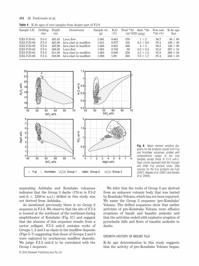
separating Ashitaka and Komitake volcanoesindicates that the Group 3 dacite (174 m in FJ-2unit-3; c. 1250 m a.s.l.) drilled in this study wasnot derived from Ashitaka.
As mentioned previously, there is no Group 2sequence in FJ-3. We observe that the site of FJ-3is located at the northeast of the northeast-facingamphitheater of Komitake (Fig. 1C) and suggestthat the absence of this sequence results from asector collapse. FJ-3 unit-2 contains rocks ofGroups 1, 2 and 3 as clasts in the mudflow deposits(Figs 5–7) suggesting that those of Groups 2 and 3were captured by scoriaceous mudflow deposits.We judge FJ-3 unit-2 to be correlated with theGroup 1 sequence.
We infer that the rocks of Group 3 are derivedfrom an unknown volcanic body that was buriedby Komitake Volcano, which has not been reported.We name the Group 3 sequence ‘pre-Komitake’Volcano. The drilled sequences show that earlieractivities of pre-Komitake Volcano were effusiveeruptions of basalt and basaltic andesite andthat the activities ended with explosive eruption ofpyroclastic falls and flows of basaltic andesite todacite.
GROWTH HISTORY OF MOUNT FUJI
K-Ar age determination in this study suggeststhat the activity of pre-Komitake Volcano began,
Table 4 K-Ar ages of core samples from deeper part of FJ-3
Sample I.D. Drillingsite
Depth(m)
Occurrence Sample wt.(g)
K2O(%)
Total 40Ar Rad. 40Ar Non rad.40Ar (%)
K-Ar age(ka)(10-9STP ml/g)
ERI-FJ3-01 FJ-3 401.85 Lava flow 1.001 0.881 370 1 � 2 99.7 30 � 80ERI-FJ3-02 FJ-3 425.90 lava clast in mudflow 1.011 0.677 135 3.5 � 0.8 97.4 160 � 40ERI-FJ3-03 FJ-3 428.90 lava clast in mudflow 1.003 0.921 480 4 � 3 99.3 120 � 90ERI-FJ3-04 FJ-3 586.30 Lava flow 1.001 0.742 69 6.2 � 0.4 91.0 267 � 16ERI-FJ3-05 FJ-3 611.30 lava clast in mudflow 1.005 0.846 258 5.5 � 1.5 97.9 200 � 50ERI-FJ3-06 FJ-3 618.80 lava clast in mudflow 1.008 1.00 305 7.8 � 1.7 97.4 240 � 50
Fig. 8 Major element variation dia-grams for the products issued from Fujiand Komitake volcanoes, plotted withcompositional ranges of the coresamples except those of FJ-3 unit-2.Open circles represent both the Youngerand Older Fuji volcanic rocks. Datasources for the Fuji products are Fujii(2007), Nakada et al. (2007) and Kanekoet al. (2004).
484 M. Yoshimoto et al.
© 2010 Blackwell Publishing Asia Pty Ltd

at least, about 270 ka and continued to about160 ka, a period of activity similar to that of Ashi-taka Volcano (Tsuya 1971; Yui & Fujii 1989). Indrill cores, the boundary between pre-Komitakeand Komitake is characterized by an alternationof a scoria fall layer and thin brown-weatheredsoil layer at a depth of 174–176.6 m in FJ-2(Fig. 3c). No soil layer is found within FJ-2 unit-2or within the sequence of Komitake lava flowsand pyroclastic layers exposed in the northernmiddle slope of Mount Fuji. The thin basal soillayer suggests that the activity of Komitakebegan shortly after that of pre-Komitake. Theactivity of Komitake continued without any hiatuslong enough for soil deposition, and the absenceof thick soil layers or reworked deposits betweenthe FJ-2 units-1 and -2 indicates successive activ-
ity, even through a change in chemistry (Older-Fuji Volcano) around 100 ka.
A schematic vertical section through MountFuji is shown in Figure 10. The peak of pre-Komitake is considered to have been locatedsouth to southeast of FJ-3, as inferred from thedips and strikes of planar structures in the mud-flows showing paleo-flow direction, which weremeasured by FMI Fullbore Formation MicroIm-ager (microresistivity formation images) as partof the logging data (Nakada et al. 2004). Thesummit of Komitake is considered to have beennortheast of the present summit of Mount Fuji(Tsuya 1971).
We can roughly estimate the total volume ofthe pre-Komitake and Komitake volcanoes byassuming the total volume of Mount Fuji as400 km3 (Tsukui et al. 1986), the analogous conicalbodies for pre-Komitake/Komitake (peaked at2300 m a.s.l.) and Mount Fuji (3776 m a.s.l.), andthe basement level of the both volcanic bodies at300 m a.s.l. The volumes of pre-Komitake/Komitake and Fuji volcanoes can be calculatedas approximately 76 and 324 km3, respectively.Long-term eruption rates of pre-Komitake/Komitake and Fuji volcanoes are 0.45 and3.3 km3/ka. The former value is within the rangeof normal subduction-related volcanoes (Tsukuiet al. 1986). Uesugi (2003) suggested that thetotal volume of eruption products from MountFuji exceeds 700 km3, considering the volume oftephra layers in the Kanto Plain. If we accept thisvalue, the long-term eruption rate of Fuji Volcanois roughly doubled. Although uncertainty remainsfor the volume of pre-Komitake/Komitake, webelieve that the eruption rate of Mount Fuji hasgreatly increased since 100 ka.
Although some episodic high eruption rates for aperiod of 1 to 10 kyr are known even in normalsubduction-related volcanoes (Table 6 of Hildreth2007), a high eruption rate for periods on the orderof 100 kyr is rare. Over 300 km3 of the magmavolume corresponds to those of large-scale,caldera-forming eruptions, though the latter isintermediate to felsic in composition. For example,the volume of pyroclastic flow deposit, Aso-4 incentral Kyushu (erupted 90 ka), is more than600 km3 (Machida & Arai 2003), which is >360 km3
as DRE (dense-rock-equivalent). This volume ofmagma had been stored in a magma chamberbeneath Aso Volcano for only 35 kyr after theeruption of Aso-3 (120 ka). After the eruption, alarge caldera formed in this volcano; however, nocaldera has formed in the Fuji Volcano. This simply
Fig. 9 SiO2-K2O and SiO2-Ba variation diagrams for ejecta from MountFuji, Ashitaka and Hakone volcanoes. Data sources for Hakone Volcanoare from Arculus et al. (1991) and Takahashi et al. (2006).
Evolution of Mount Fuji 485
© 2010 Blackwell Publishing Asia Pty Ltd

means that mafic magma had oozed nearly con-tinuously from Mount Fuji.
The period between 160 ka, when pre-KomitakeVolcano ceased its activity, and 100 ka, whenFuji Volcano became active, is characterized bychanges in the mode of eruptions in other volca-noes near Mount Fuji. Hakone Volcano changedfrom caldera-forming eruptions to central conedevelopment around 150 ka (Takahashi et al.2006). In the Izu Peninsula, volcanic activitychanged from polygenetic to monogenetic around150 ka, reflecting a change in tectonic stress field(Koyama & Umino 1991; Hasebe et al. 2001). Thedrastic change in the volcanic system of MountFuji, from normal subduction-related volcanism tobasalt-dominant Fuji volcanism, may have beencaused by a change in tectonic framework.
CONCLUDING REMARKS
In scientific drilling on the northeastern flankof Mount Fuji, a new volcanic series (‘pre-Komitake’ Volcano) was found beneath rocks of theKomitake Volcano, previously considered to be theoldest volcano within the Mount Fuji edifice. Anupdated history of Mount Fuji starts with erup-tions of pre-Komitake volcano from >about 270 to160 ka, followed by eruptions of Komitake Volcanofrom about 160 to 100 ka, Older-Fuji from 100 to20 ka and Younger Fuji < 20 ka. Pre-Komitake,Komitake and Fuji Volcanoes are easily distin-guishedin variation diagrams of MgO vs. SiO2, and TiO2
vs. MgO. The pre-Komitake volcanic rocks arecharacterized by hornblende-bearing andesite anddacite together with low-K2O basalt and basalticandesite.
Incompatible element abundances increase withincreasing SiO2 in the pre-Komitake rocks, which
is commonly found in volcanoes in the northernIzu-Bonin arc, in contrast to decoupling of incom-patible elements with SiO2 in Fuji Volcano. Thelong-term eruption rate at Mount Fuji drasticallyincreased around 100 ka, when Fuji Volcanobecame active. The change in volcanism of MountFuji may have been induced by a change in thetectonic framework related to the subduction ofthe Philippine Sea Plate.
ACKNOWLEDGEMENTS
The authors thank Drs S. Aramaki, T. Shimano,S. Nakano, Y. Ishizuka, N. Miyaji and D. Miurafor discussions about Mount Fuji. Thanks also tothe Geothermal Engineering Co., Ltd, particu-larly chief engineer Mr S. Sakuma, KawasakiGeological Engineering Co. Ltd, and drillingoperators. XRF analysis was supported by K.Komori and S. Kitazawa. An early version of themanuscript was improved by Dr T. Wright. Wealso thank Drs A. Takada, S. Umino and ananonymous reviewer for their constructive com-ments. Drilling was financially supported by aSpecial Coordination Fund for Promoting Scienceand Technology from the Ministry of Education,Culture, Sports, Science and Technology ofJapan.
REFERENCES
AMANO K. 1991. Multiple collision tectonics of the SouthFossa Magna in central Japan. Modern Geology 15,315–29.
ANMA S. 2007. Lahars and slush lahars on the slopesof Fuji volcano. In Aramaki S., Fujii T., Nakada S. &Miyaji N. (eds.) Fuji Volcano, pp. 285–301, Yama-nashi Institute of Environmental Science, Fujiy-oshida (in Japanese with English abstract).
Fig. 10 Schematic north-south cross-section through Mount Fuji, showing the relation of volcanic piles (Younger- and Older-Fuji, Komitake, pre-Komitake and Ashitaka volcanoes) with age (ka) and SiO2 (wt%).
486 M. Yoshimoto et al.
© 2010 Blackwell Publishing Asia Pty Ltd

ARCULUS R. J., GUST D. A. & KUSHIRO I. 1991. Fuji andHakone. National Geographic Research and Explo-ration 7, 276–309.
FUJII T. 2001. Detecting the activity of Mt. Fuji. Kagaku71, 1595–600 (in Japanese).
FUJII T. 2007. Magmatology of Fuji volcano. In AramakiS., Fujii T., Nakada S. & Miyaji N. (eds.) FujiVolcano, pp. 233–44, Yamanashi Institute of Environ-mental Science, Fujiyoshida (in Japanese withEnglish abstract).
HASEBE N., FUKUTANI A., SUDO M. & TAGAMI T. 2001.Transition of eruptive style in an arc-arc collisionzone: K-Ar dating of Quaternary monogenetic andpolygenetic volcanoes in the Higashi-Izu region, Izupeninsula, Japan. Bulletin of Volcanology 63, 377–86.
HILDRETH W. E. 2007. Quaternary magmatism in theCascades – Geologic perspectives. U. S. GeologicalSurvey Professional Paper 1744, 1–125.
KANEKO T., YASUDA A., YOSHIMOTO M., SHIMANO T.,FUJII T. & NAKADA S. 2004. Magmatic features andthe magma plumbing system of Mt Fuji. ChikyuMonthly Special Volume 48, 146–52 (in Japanese).
KOYAMA M. & UMINO S. 1991. Why does the Higashi-Izu monogenetic volcano group exist in the Izu Pen-insula? Relationships between late Quaternaryvolcanism and tectonics in the northern tip of theIzu-Bonin arc. Journal of Physics of the Earth 39,391–420.
KUNO H. 1968. Differentiation of basalt magmas. InHess H. H. & Poldervaart A. A. (eds.) Basalts: ThePoldervaart Treatise on Rocks of Basaltic Composi-tion, vol. 2, pp. 623–88, Interscience Publishers, NewYork.
LEES J. M. & UKAWA M. 1992. The south Fossa Magna,Japan, revealed by high-resolution P and S wavetravel time tomography. Tectonophysics 207, 377–96.
MACHIDA H. 1964. Tephrochronological study ofVolcano Fuji and adjacent areas. Journal of Geogra-phy 73 (293–308), 337–50 (in Japanese with Englishabstract).
MACHIDA H. 2007. Development of Fuji volcano: Areview from Quaternary tephrochronology. InAramaki S., Fujii T., Nakada S. & Miyaji N. (eds.)Fuji Volcano, pp. 29–44, Yamanashi Institute ofEnvironmental Science, Fujiyoshida (in Japanesewith English abstract).
MACHIDA H. & ARAI F. 2003. Atlas of Tephra in andaround Japan. University of Tokyo Press, Tokyo.
MATSUMOTO A. 1989. Improvement for determination ofpotassium in K-Ar dating. Bulletin of the GeologicalSurvey of Japan 40, 65–70 (in Japanese with Englishabstract).
MATSUMOTO A. & KOBAYASHI T. 1995. K-Ar age deter-mination of late Quaternary volcanic rocks using the‘mass fractionation correction procedure’: Applica-tion to the Younger Ontake Volcano, central Japan.Chemical Geology 125, 123–35.
MIYAJI N. 1988. History of younger Fuji Volcano.Journal of the Geological Society of Japan 94,433–52 (in Japanese with English abstract).
MIYAJI N., ENDO K., TOGASHI S. & UESUGI Y. 1992.Tephrochronological History of Mt. Fuji. In Kato H.& Noro H. (eds.) 29th IGC Field Trip Guide Book,Vol. 4, Volcanoes and Geothermal Fields of Japan,pp. 75–109. Geological Survey of Japan, Tsukuba.
NAKADA S., YOSHIMOTO M., KANEKO T., SHIMANO T.& FUJII T. 2004. Outline of scientific drilling at MtFuji. Chikyu Monthly Special Volume 48, 146–52 (inJapanese).
NAKADA S., YOSHIMOTO M. & FUJII T. 2007. Pre-Fujivolcanoes. In Aramaki S., Fujii T., Nakada S. &Miyaji N. (eds.) Fuji Volcano, pp. 69–77, YamanashiInstitute of Environmental Science, Fujiyoshida (inJapanese with English abstract).
NAKAMICHI H., WATANABE H. & OHMINATO T. 2007.Three-dimensional velocity structures of Mount Fujiand the South Fossa Magna, central Japan. Journalof Geophysical Research 112, B03310; doi:10.1029/2005JB004161.
SENO T. 2005. Izu detachment hypothesis: A proposal ofa unified cause for the Miyake-Kozu event and theTokai slow event. Earth, Planets and Space 57, 925–34.
STEIGER R. H. & JÄGER E. 1977. Subcommission ongeo-chronology: Convention on the use of decay con-stants in geo- and cosmochronology. Earth andPlanetary Science Letters 36, 359–62.
TAKAHASHI M. 2000. Magma plumbing system and tec-tonics setting of Mt Fuji – Mini ocean ridge model-.Chikyu Monthly 22, 281–96 (in Japanese).
TAKAHASHI M. 2007. Mystery of the structurebeneath Mount Fuji. Kagaku 77, 1274–82 (inJapanese).
TAKAHASHI M., NAITO S., NAKAMURA N. & NAGAI M.2006. Whole-rock chemistry for eruptive products ofOlder and Younger central cone in Hakone volcano,central Japan. Proceedings of the Institute ofNatural Sciences, Nihon University 41, 151–86 (inJapanese with English abstract).
TSUKUI M., SAKUYAMA M., KOYAGUCHI T. & OZAWA K.1986. Long-term eruption rates and dimensions ofmagma reservoirs beneath Quaternary polygeneticvolcanoes in Japan. Journal of Volcanology andGeothermal Research 29, 189–202.
TSUYA H. 1962. Geological and petrological studies ofvolcano Fuji, VI. 6. Geology of the volcano asobserved in some borings on its flanks. Bulletin of theEarthquake Research Institute 40, 767–804.
TSUYA H. 1968. Geology of Volcano Mt. Fuji. Explana-tory text of geologic map 1:50,000 scale. GeologicalSurvey of Japan, Kawasaki.
TSUYA H. 1971. Topography and Geology of Volcano Mt.Fuji: Results of the Co-Operative Scientific Surveyof Mt. Fuji. Fuji Kyuko Co. Ltd., Tokyo (in Japanesewith English abstract).
Evolution of Mount Fuji 487
© 2010 Blackwell Publishing Asia Pty Ltd

UESUGI Y. 2003. Geographical Guidebook of FujiVolcano. Geological Society of Japan, Kanto Branch(in Japanese).
UKAWA M. 2005. Deep low-frequency earthquakeswarm in the mid crust beneath Mount Fuji (Japan)in 2000 and 2001. Bulletin of Volcanology 67, 47–56.
UTO K., CONREY R. M., HIRATA T. & UCHIUMI S.1995. Improvements of the K-Ar dating systemat Geological Survey of Japan. Introduction ofcomputer-controlled mass-spectrometry and pipettespike reservoir. Bulletin of Geological Survey ofJapan 46, 239–49 (in Japanese with Englishabstract).
YAMAMOTO T., TAKADA A., ISHIZUKA Y. & NAKANO S.2005. Chronology of the products of Fuji volcanobased on new radiometric carbon ages. Bulletin ofthe Volcanological Society of Japan 50, 53–70 (inJapanese with English Abstract).
YAMAOKA K. 1995. Shape of subducting PhilippineSea Plate and its relation to Tokai earthquake.Chikyu Monthly Special Volume 14, 116–24 (inJapanese).
YUI M. & FUJII T. 1989. Geology of Ashitaka volcano,Central Japan. Bulletin of the Earthquake ResearchInstitute 64, 347–89 (in Japanese with EnglishAbstract).
488 M. Yoshimoto et al.
© 2010 Blackwell Publishing Asia Pty Ltd