Evolution of historical riveted connections: joining ... · Evolution of historical riveted...
12
Evolution of historical riveted connections: joining typologies, installation techniques and calculation methods Q. Collette, I. Wouters & L. Lauriks Department of Architectural Engineering (ARCH), Vrije Universiteit Brussel, Belgium Abstract Riveting was one of the major joining techniques used for the assembly of iron and steel structures. Being widely used since 1860, today most of the existing riveted structures need maintenance and possibly strengthening. This research aims to improve the existing knowledge on this type of fasteners in order to stimulate less intrusive interventions during renovation, respecting the historical character of these structures. To reach this goal, a multidisciplinary literature study is carried out, dealing with three related topics: historical analysis (historical context, fields of use, types of riveted connections, comparison with other contemporary joining techniques), technical subjects (definition, material, joining typologies, forms of the rivet head, installation processes and techniques) and structural understanding (bearing principle, strength of riveted connections, calculation methods). Keywords: riveted connections, iron and steel, historical analysis, technical know-how, structural understanding, joining typologies, installation techniques, calculation methods. 1 Introduction Although considered as an emblematic type of fastener characterizing 19 th and 20 th century iron and steel constructions, riveted connections were first introduced by two other branches of industry, namely boilermaking and the shipbuilding industry. Thanks to the advent of the industrial revolution and the major technological innovations of the iron and steel industry, rivets became massively and widely used for various constructions (civil engineering, Structural Repairs and Maintenance of Heritage Architecture XII 295 www.witpress.com, ISSN 1743-3509 (on-line) WIT Transactions on The Built Environment, Vol 118, © 2011 WIT Press doi:10.2495/ 10251 STR1
Transcript of Evolution of historical riveted connections: joining ... · Evolution of historical riveted...

Evolution of historical riveted connections: joining typologies, installation techniques and calculation methods
Q. Collette, I. Wouters & L. Lauriks Department of Architectural Engineering (ARCH), Vrije Universiteit Brussel, Belgium
Abstract
Riveting was one of the major joining techniques used for the assembly of iron and steel structures. Being widely used since 1860, today most of the existing riveted structures need maintenance and possibly strengthening. This research aims to improve the existing knowledge on this type of fasteners in order to stimulate less intrusive interventions during renovation, respecting the historical character of these structures. To reach this goal, a multidisciplinary literature study is carried out, dealing with three related topics: historical analysis (historical context, fields of use, types of riveted connections, comparison with other contemporary joining techniques), technical subjects (definition, material, joining typologies, forms of the rivet head, installation processes and techniques) and structural understanding (bearing principle, strength of riveted connections, calculation methods). Keywords: riveted connections, iron and steel, historical analysis, technical know-how, structural understanding, joining typologies, installation techniques, calculation methods.
1 Introduction
Although considered as an emblematic type of fastener characterizing 19th and 20th century iron and steel constructions, riveted connections were first introduced by two other branches of industry, namely boilermaking and the shipbuilding industry. Thanks to the advent of the industrial revolution and the major technological innovations of the iron and steel industry, rivets became massively and widely used for various constructions (civil engineering,
Structural Repairs and Maintenance of Heritage Architecture XII 295
www.witpress.com, ISSN 1743-3509 (on-line) WIT Transactions on The Built Environment, Vol 118, © 2011 WIT Press
doi:10.2495/ 10251STR1

private/public buildings) and applications (trussed beams, built-up shapes,…). Though less visible, the riveting technology experienced an important dimensional, conceptual (design) and technical evolution over time. As a consequence, today’s engineers and architects have to manage this complexity on a regular base, given the large number of historical structures that need renovation or maintenance. The literature study presented in this paper aims to provide – by combining historical, technical and structural aspects – the necessary know-how to understand the original design and to assess the historical character of the structure, at the micro-level of its joints. To reach this goal, international (Belgium, France, the United Kingdom, the Netherlands) historical handbooks, patents and norms were consulted, in combination with more recent reference works [1, 2].
2 Historical context
As early as 3000 BC, the rivet made its first appearance in Egypt as a joining element for the manufacturing of several tools and objets d’art (e.g. fixing a handle on jars). Later, it became a fastener commonly used during the Gallo-Roman era. Already, they designed a kind of rivet mould – the ancestor of the cup tool commonly called these days “bouterolle” – to joint metallic plates (boilerwork). In a more recent past, the Vikings resorted to rivets for installing the planking of their boats in the 7th and the 8th century [1, 2].
2.1 1840-1930, the heyday of rivets
The development of the riveting technique and its applicability in practice is closely correlated with improvement and evolution of the materials to be joined. For instance, as long as wooden constructions were approved by a large majority and widely used, riveted connections, given the large thickness of the to assemble parts and other structural disadvantages (e.g. buckling of the rivet shank, splitting risk, ...), were not a fitted and convenient alternative. On the other hand, important developments in the field of iron and steel industry since the beginning of the 19th century allowed to overcome the main barrier to entry, namely the overall thickness of the joint. Shapes made of wrought iron and (mild) steel, with their slender cross sections and their more ductile behaviour in comparison with cast iron (impossible to rivet), stimulated and symbolized the dawn of a new “joining era” [3]. From 1840 onwards, riveted connections became the most important joining technique within different fields that followed and overlapped each other. The use of rivets had experienced several – formal, constructional and theoretical – renewals and evolutions, being in phase with industrial and technical “brainwaves” of that time (e.g. new materials, manufacturing process, installation techniques,...). The heyday of rivets started to decline around 1930, supplanted step-by-step by another joining technique: electric arc welding [1, 2].
296 Structural Repairs and Maintenance of Heritage Architecture XII
www.witpress.com, ISSN 1743-3509 (on-line) WIT Transactions on The Built Environment, Vol 118, © 2011 WIT Press

2.2 Fields of use
In contrast with the welding technique that characterizes one major field of use (metallic constructions), rivets benefitted from a larger applicability within the industrial landscape. From 1810 onwards, the boilermaking was the first to introduce hot riveting, namely heating the rivet before riveting. Steam engines and later locomotive’s boilers were manufactured thanks to this technique until the beginning of the 20th century. The shipbuilding industry is the second field of use (1830-1940). This can be explained by the exponential growth of the maritime traffic and commercial exchanges. Around 1840, riveted connections made their appearance in the last major industrial sector: iron and steel constructions. Riveting, as a new way to assemble elements together, influenced and contributed to rationalize the manufacturing processes of this industry already at the design stage. Moreover, riveted connections gave an answer vis-à-vis the expectations and wishes of engineers and architects (e.g. Art Nouveau architect Victor Horta) who wanted to explore new formal and conceptual languages (apparent lightweight structures, transparency in combination with glass, ...), according to the social, economical and cultural mutations of that time [4]. The typical applications of riveted connections for metallic constructions can be merged into two main groups: civil engineering and public/private buildings. Although the built structures of the first group, mainly motorway and railway bridges, are better-known, several smaller scaled constructions met in buildings were joined with rivets, for example winter gardens, industrial and exhibition halls, private houses, department stores and schools. From a more local point of view, this fastener has two principal functions: connecting structural elements and manufacturing built-up shapes. Portal frames and trussed beams are representative examples of typologies where rivets, often in combination with bolts, connect, with or without additional connecting element (angle shape, gusset,...), iron and steel plates together. The second main function is related to the manufacturing of composed beam types made of shapes or twin beams (built-up girders and columns) [4]. The advent of both a new joining technique and a new material, respectively welding and (reinforced) concrete, led from 1920-30 riveted connections on a slippery slope regarding their use in the building sector [1].
2.3 Rivets versus bolts and welding
Rivets are fixed, in opposition with mobile connections, and permanent which means they cannot be dismantled. In comparison with bolts, their main advantages are their cheapness and the better stiffness provided to the joints. On the other hand, bolts will be privileged in case of large diameters and/or length of the shank, required dismantling, joining of cast iron shapes, etc. Regarding welding, its first technical diseases and the generated distrusted climate explain why riveted connections were still in use until 1970. Nevertheless, structural (self weight, weakening of the structure [rivet holes]), financial (labour costs)
Structural Repairs and Maintenance of Heritage Architecture XII 297
www.witpress.com, ISSN 1743-3509 (on-line) WIT Transactions on The Built Environment, Vol 118, © 2011 WIT Press

and practical (noisy/difficult job) issues sounded the death knell for riveting connections that were, from 1940 onwards, gradually replaced by welding [1, 5].
3 Rivets, definition and technique
3.1 What’s a rivet?
According to Francken [6], a rivet consists of a cylindrical shank and a rivet head, usually rounded: “Le rivet est une sorte de clou à section cylindrique et à tête ordinairement ronde qui sert à assembler les tôles et dont l’extrémité a été aplatie et élargie après coup de façon à former une seconde tête.”. The rivet is put through the rivet hole and a second rivet head is formed – the forged head – to pull the connecting elements towards each other, fig. 1.
Figure 1: (Left) Example of a rivet and its original round head [7]. (Right) The three main components of a rivet (single lap joint): (A) the rivet shank, (B) the forged head and (C) the original head [8].
Study of historical sources shows that engineers, theorists and builders of the time were aware of the importance of rivets as a critical part within the whole structure. The choice of material for manufacturing a rivet, which is an initial crucial aspect, was the subject of many discussions and debates [9]. In most cases, it was preferable to opt for a material with approximately the same or slightly lower mechanical properties than these of the elements to be joined. Even if the quality and the price of steel rivet were satisfactory, iron and puddle iron were still considered as the best alternative at the end of the 19th century. Indeed, before the development and the widespread use of mechanical riveting (1895-1910), the difficult installation processes discredited rivets made of steel, which was even forbidden by some countries, such as Russia, for the connection of steel plates and/or shapes [5]. Then, results of experimental tests were published by several authors such as Frémont [10] on the strength of materials. Combined with the growing awareness on the importance of the quality of the rivet, these experiments reconciled engineers and builders with the use of steel rivets (e.g. “extra mild steel”) [3, 11].
298 Structural Repairs and Maintenance of Heritage Architecture XII
www.witpress.com, ISSN 1743-3509 (on-line) WIT Transactions on The Built Environment, Vol 118, © 2011 WIT Press

3.2 Rivet head: the reflection of structural, constructional and financial aspects
At first, a large formal and dimensional variety of rivets heads was available. The broad dimensional diversity had been channelled and rationalized via norms from the 1920s onwards. At the same time, given their expensiveness and complex manufacturing, particular forms of rivet heads fitted for a specific use were “naturally” ousted [2]. The choice of a rivet head depends on the joining type (load and/or fluid tight riveting), practical matters (installation) and aesthetic considerations. Different forms were utilized for both the original and the forged rivet head, which were not necessarily the same per rivet. The main types of rivet heads, irrespective of the field of use, are: round, countersunk, coned and flat heads. For iron and steel constructions, the round head was the most common one. Moreover, these forms were a research subject during approximately 100 years. The main parameters that characterized this evolution are the improvement of installation methods, results of experiments, and financial aspects. From 1820 onwards, the development of manufacturing machines and later riveting machines generated the progressive dominance of the round head, to the detriment of the coned head. Also, research on the weight and the price of riveted connections, especially on the head depth (h), was carried out. As a result, the “round head” made room for two derived improved forms: the round snap head (perfectly hemispheric, higher head depth) and a more flattened version, the button head also called “en goutte de suif” (with two radiuses of curvature) [2, 5].
Table 1: (Left) List of authors/organisation and the date of their publication. (Right) Evolution of the design proportion of round head: ratio “D/d” (diameter of the head/diameter of the shank) and ratio “h/d” (head depth/diameter of the shank).
Structural Repairs and Maintenance of Heritage Architecture XII 299
www.witpress.com, ISSN 1743-3509 (on-line) WIT Transactions on The Built Environment, Vol 118, © 2011 WIT Press

Quantitative results of this literature study, which confronts publications of several authors [1, 3, 6–9, 12, 13], clearly show the formal evolution of the round head to one of its follower namely the round snap head (hemispheric): decreasing values of the “D/d” ratio combined with increasing values of the “h/d” ratio, tab. 1. This can be partially explained by the need for a clear distinction between this new version of the round head – the round snap head – and the flattened form of the button head.
3.3 Installation techniques
The installation process of a rivet includes two main steps: making the rivet hole via punching, drilling or a combination of both and riveting. Different techniques among the riveting process are applied: hot versus cold riveting and manual versus mechanical riveting. Being only suitable for small diameters (8–9 [mm]) and soft materials, cold riveting was not widely spread. On the other hand, manual and later mechanical hot riveting, thanks to its positive effect on the strength of the joint, was the predominant used technique (shop and field riveting). After the rivet was made red-hot by the forge boy, the riveter forges the second head with a riveting hammer eventually fitted with a snap or cup tool (mould called “bouterolle”), while another person – the holder-on – blocks the original rivet head with a dolly bar. This is called manual riveting, fig. 2.
Figure 2: Riveting set for manual riveting: (A) the dolly bar, (B) the cup tool (“bouterolle”), (C) the hand-held hammer and (D) the rivet [14].
Being tough work and incompatible with large diameters, mechanization of the riveting process was needed. From 1850 onwards, riveting machines were introduced. They combine two effects – simultaneously fixing the original head and forging the second one via a compression force – and increase the shear strength of the joint, thanks to a better upsetting of the shank. The first machines were supplied by steam pressure, followed by hydraulic and electric power. Around 1870, portable riveting machines were designed in order to facilitate and speed up the work. After 1910, the development of pneumatic hammers permanently replaced manual riveting [9, 15, 16].
3.4 Joining typologies
Based on the number of plates to be joined, a distinction is made between two joining types: single and double lap joint. For the first one, the rivet shank is
300 Structural Repairs and Maintenance of Heritage Architecture XII
www.witpress.com, ISSN 1743-3509 (on-line) WIT Transactions on The Built Environment, Vol 118, © 2011 WIT Press

loaded via one shear plane (2 joined plates) while two shear planes have to bear loads in the second case (3 joined plates), fig. 3. As a result, half of the amount of rivets is needed with double lap joints in comparison with single ones, for a given loading case.
Figure 3: (Left) Single and double lap joint with (strap) or without cover plates: (A) & (B) shear plane(s) and (C) the cover plate. (Right) Examples of end to end (above) and perpendicular (below) joints [6].
Furthermore, a distinction is made between end to end and perpendicular joints, fig. 3. Overlaps – single, double or triple riveted lap (depending on the number of rivets and the required strength) – are needed in case of end to end connections of plates in the same plane. The presence of unwanted forces (e.g. bias tension) in the overlap zone of asymmetric joints can be avoided by using strap joints, with one or two cover plates. Perpendicular joints are most of the time constructed with the use of connecting plates (e.g. angle shapes). In practice, the use of strap joints was privileged and promoted, despite their more expensive installation (labour cost). Indeed, without cover plates, the collapse mechanism will occur for lower loading cases. In particular, given their doubly symmetric geometry and the fact that each rivet shank is under double shear, strap joints with two cover plates provide a higher resistance against instability and represent an optimal choice [5, 17, 18].
4 Structural understanding
The design of a riveted connection involves a large number of parameters: the joining typology (lap joint versus strap joint, use of cover plates), mechanical properties (material) and geometrical aspects (diameter, number and setting of rivets, distances,...). Due to this complexity and a lack of structural understanding (development of the strength of materials), empirical methods and practical rules were often used, derived from the personal experience of builders (not scientifically deduced). From the second half of the 19th century onwards, experiments carried out by engineers – such as the acknowledged Englishman
Structural Repairs and Maintenance of Heritage Architecture XII 301
www.witpress.com, ISSN 1743-3509 (on-line) WIT Transactions on The Built Environment, Vol 118, © 2011 WIT Press

William Fairbairn – helped to reconcile and to increase the interactions between technique and science. Later, norms and standards were published, integrating new formulas that met the new structural requirements (increasing span length and internal stresses) and took the evolution of materials into account [1, 2].
4.1 Bearing principle and strength of riveted connections
The bearing principle of a riveted joint resulted from two combined effects: friction between the connected elements (blocking effect) and the shear strength of rivets. The joined plates are pinched towards each other by the rivet heads because of the shrinkage of the rivet shank (prestressing), while cooling down after the hot riveting process. When external forces exceed the adhesive strength of the plates, the friction effect is cancelled and the only remaining contribution is the shear strength of the rivet. For this reason, many authors proposed to ignore the blocking effect when designing the joints. This approach was safe and took into account a potential incomplete upset of the rivet shank in the rivet hole (installation imperfections) [7, 8]. A properly executed riveted connection should validate the three following requirements: resistance of the joint against shearing (via the rivet cross-section), avoiding the crippling (via the ratio “d/e”) and tearing (via minimal distances) of the joined plates. Typical collapse mechanisms of riveted connections are: tearing off of the rivet head (slant position), failure of the rivet under shear, failure of the plate nearby the rivet holes and crippling of the plates [11, 17]. When norms and standards were available, the diametral compression was discussed and introduced in addition to the shear strength. This is the pressure applied by the loaded joined plates (inner surface of the rivet hole) on the rivet shank. For rivets under double shear, the Belgian A.B.S. norm recommended the minimal value between the results derived from the shear calculation and these of the diametral compression, as allowable load to consider, fig. 4. These
Figure 4: Allowable load for a rivet under double shear in function of its diameter (d) and the thickness of the joined plates (e): loading case N°1 (dead load + static variable load of lifting/handling).
e = 6 [mm]e = 7 [mm]e = 8 [mm]e = 9 [mm]e = 10 [mm]e =11 [mm]Double shear
0.0
10.0
20.0
30.0
40.0
50.0
60.0
70.0
80.0
90.0
8 10 12 14 16 18 20 22
All
owab
le lo
ad [
kN]
d [mm]
Diametral compression
302 Structural Repairs and Maintenance of Heritage Architecture XII
www.witpress.com, ISSN 1743-3509 (on-line) WIT Transactions on The Built Environment, Vol 118, © 2011 WIT Press
recommendations were based on the following permissible strengths: 110 [MPa] for the shear strength and 320 [MPa] for the diametral compressive strength (mild steel) [7, 13].
4.2 Evolution of the design principles
Two opposing theories, available in the literature, lead to quite different design principles and results: authors that only took the blocking effect into account and the ones that considered the shear strength. Later, the majority of these theorists agreed that a combined action of both contribute to the overall strength of the riveted joints. However, in practice, the shear strength was the predominant design criterion, considered as the most “rational” one [3]. Calculating the shear strength as a ratio of the tensile strength was a frequent adopted choice. Many authors estimated the shear strength being equal to 80% of the tensile strength. Indeed, they assumed that the strength of a rivet shank vis-à-vis shearing is comparable to the strength of a plate under traction. Mister Fairbairn, with his research, added important information and refined this theory by making a distinction between connections with or without cover plates [5, 18]. A first common practice consisted of equalling the allowable traction force of the joined plates (net cross-section) with the permissible shear force of the rivets. This means that only geometrical and mechanical (allowable stress) parameters are taken into account, regardless of the applied loads. This underlines the fact that most of engineers and/or theorists postulated that the connection plates and the rivets have the same permissible load (uniformity). As a result, by equalling the two members, both safety stresses are cancelled and the final design of the joint is deduced from geometrical parameters [5, 17]. Later, the relevance of the calculation’s reasoning had been improved. A major factor was the required number of rivets (n) which depends on the geometry of the joint ((a) equals one or two, depending on the number of shear planes), the diameter of the rivet (d), the allowable shear strength (R) – called “taux de travail au cisaillement”- and the external load (P), eqn. (1). The ratio “d/e” influences the calculations in order to solve this equation with two unknowns (n and d) [7, 8].
(1)
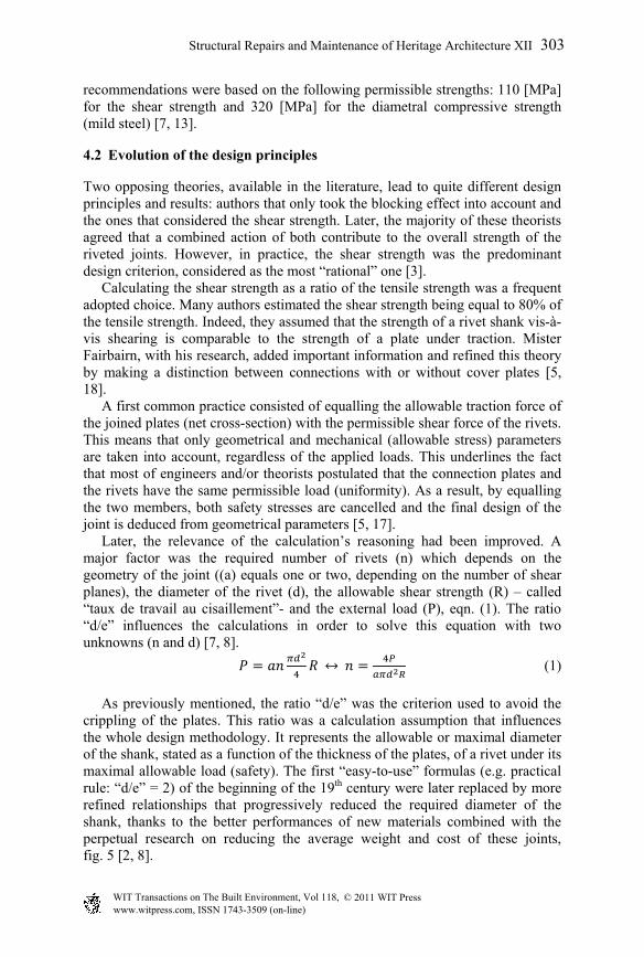
As previously mentioned, the ratio “d/e” was the criterion used to avoid the crippling of the plates. This ratio was a calculation assumption that influences the whole design methodology. It represents the allowable or maximal diameter of the shank, stated as a function of the thickness of the plates, of a rivet under its maximal allowable load (safety). The first “easy-to-use” formulas (e.g. practical rule: “d/e” = 2) of the beginning of the 19th century were later replaced by more refined relationships that progressively reduced the required diameter of the shank, thanks to the better performances of new materials combined with the perpetual research on reducing the average weight and cost of these joints, fig. 5 [2, 8].
Structural Repairs and Maintenance of Heritage Architecture XII 303
www.witpress.com, ISSN 1743-3509 (on-line) WIT Transactions on The Built Environment, Vol 118, © 2011 WIT Press

Figure 5: Evolution of the “d/e” ratio (1857; > 1900; 1929) in comparison with two practical rules (constant values of the ratio).
Regarding the setting of rivets (distances between axles, edge distances, end distances), the formulas of Schwedler were often used. Moreover, his design rules and tables, exclusively based on the shear strength and ignoring the strength of the plates against slipping (blocking effect), were considered as a reference [11]. Nevertheless, these theoretical aspects need to be placed into the practical context. Indeed, the number of the utilized diameters (rivet shank) was generally limited to two or three types (generally even number in [mm]) per structure, in order to avoid the multiplication of the needed tools (drill, snap tool,...), especially for manual riveting [7, 12].
5 Conclusion
Thanks to an in-depth literature study covering more than one century, this multidisciplinary analysis provides insights into the riveting theory and practice, especially applied to iron and steel constructions. The combined results of the historical, technical and structural investigations stress the importance of confronting the original design of a riveted joint with its historical context, characterized by joining typologies, installation techniques and calculation methods peculiar to a certain time period. In spite of the perpetual research of engineers on mechanizing and automating the riveting process, traditional practices and the experience of riveters have still played a leading predominant role. In the same idea, improvements of the design principles and calculation methods, despite the willingness to study and rationalize the dimensions of these joints, were in fact a kind of “mathematical translations” of the practice, know-how and experience in the field. As a consequence, by highlighting the richness and the complexity of the riveting technique, this research contributes to increase the knowledge about rivets, which is an essential first-stage step when assessing
1
1.5
2
2.5
3
3.5
4 6 8 10 12 14 16 18 20 22
Rat
io [
/]
e [mm]
Practical rule: d/e = 2
Practical rule: max(d/e)
Armengaud (1857) via Lemaître (1856)
General rule (> 1900)
Champly (1929)
304 Structural Repairs and Maintenance of Heritage Architecture XII
www.witpress.com, ISSN 1743-3509 (on-line) WIT Transactions on The Built Environment, Vol 118, © 2011 WIT Press

the renovation potential of heritage constructions and their associated historical character.
Acknowledgements
The research presented in this paper is funded by the Research Foundation – Flanders (FWO Vlaanderen, Belgium). We would like to thank Mister Bruno Jacomy (Executive Director of the “Musée des Confluences”, Lyon, France) for his kind help.
References
[1] Truijens, P., Klinken: een historische verbindingswijze voor staalconstructies. Monumenten en Landschappen, 20(4), pp. 45-64, 2001.
[2] Jacomy, B., De l’objet à l’homme. Rivets et riveurs à travers la civilisation industrielle, PhD in social psychology (Université Louis Pasteur – Strasbourg 1), Strasbourg (unpublished), 1983.
[3] Combaz, P., La Construction. Principes et applications, vol. 3, part 7, E. Lyon-Claesen: Bruxelles, pp. 10-84, 1897.
[4] Collette, Q., Wouters, I., de Bouw, M., Lauriks, L. & Younes, A., Victor Horta’s iron architecture: a structural analysis. Proc. of the 7th Int. Conf. on Structural Analysis of Historic Constructions, Strengthening and Retrofitting, eds: Xianglin Gu & Xiaobin Song, vol. 133-134, pp. 373-378, 2010.
[5] Combaz, P., La Construction. Principes et applications, vol. 2, part 3, E. Lyon-Claesen: Bruxelles, pp. 43-175, 1897.
[6] Francken, D., La construction civile. Les matériaux et leur mise en œuvre, A. De Koninckx: Anvers, pp. 328, 1910.
[7] Nachtergal, A., Charpentes métalliques. Calculs et construction, 5th Ed., Bieleveld: Bruxelles, pp. 30-259, 1937.
[8] Dechamps, H., Les principes de la construction des charpentes métalliques et leurs applications aux ponts à poutres droites, combles, supports et chevalements, H. Vaillant-Carmanne: Liége, pp. 87-145, 1888.
[9] Van Drunen, J., L’acier dans la construction (Bibliothèque belge des connaissances modernes), Charles Rozez: Bruxelles, pp. 250, 1892.
[10] Frémont, C., Etude expérimentale du rivetage, Société d’encouragement pour l’industrie nationale: Paris, 1906.
[11] Aerts, L., Éléments pratiques de la résistance des matériaux, 4th Ed., J. Wouters-Ickx and Librairie Polytechnique Ch. Bélanger: Louvain and Paris-Liége, pp. 23-50, 1911.
[12] Zwiers, L., Handboek der burgerlijke bouwkunde. IJzerconstructies, 2nd Ed., V/H. Van Mantgem & De Does: Amsterdam, pp. 19-50, 1916.
[13] Association Belge de Standardisation (A.B.S.), Standardisation des boulons et rivets (Rapport N°6), A.B.S.: Bruxelles, pp. 16, 1941.
[14] Lineham, W.J., A text-book of mechanical engineering, Chapman & Hall: London, pp. 285, 1902.
Structural Repairs and Maintenance of Heritage Architecture XII 305
www.witpress.com, ISSN 1743-3509 (on-line) WIT Transactions on The Built Environment, Vol 118, © 2011 WIT Press

[15] Simmons, D.A., The continuous clatter: practical field riveting. The journal of the Society for Industrial Archaeology, 23(2), pp. 4-20, 1997.
[16] Collette, Q., Iron and Steel: Manufacturing and connection techniques (1830-1940), Patents Database “DB3” (Excel file), 2010.
[17] De Vos, N., Cours de construction donné de 1864 à 1874 à la section du génie de l’école d’application de Bruxelles, vol. 1, Librairie Polytechnique De Decq & Duhent: Bruxelles, pp. 95-100, 1879.
[18] Aerts, L., Éléments pratiques de la résistance des matériaux, Aug. Fonteyn: Louvain, pp. 1-27, 1886.
306 Structural Repairs and Maintenance of Heritage Architecture XII
www.witpress.com, ISSN 1743-3509 (on-line) WIT Transactions on The Built Environment, Vol 118, © 2011 WIT Press