
EVL+Strace: a novel bidirectional model transformation ...
75
EVL+Strace: a novel bidirectional model transformation approach Leila Samimi-Dehkordi, Bahman Zamani * , Shekoufeh Kolahdouz-Rahimi MDSE Research Group, Department of Software Engineering, University of Isfahan, Isfahan, Iran Abstract Context: Model transformation, as one of the cornerstones of Model-Driven Engineering (MDE) paradigm, produces target models from source models. In most of the practical cases, both source and target models are changed inde- pendently and it is essential to preserve the consistency between them. Bidi- rectional transformation (Bx) provides a mechanism to re-establish this inter- model consistency. Bx approaches suffer from several limitations, such as lack of a comprehensive implementation, low learnability, and mismanagement of update conflicts. Objective: To alleviate the aforementioned drawbacks, we propose a novel Bx approach, called EVL+Strace, which is built using the Epsilon Validation Lan- guage (EVL) on a domain-specific trace metamodel (Strace). Furthermore, an Eclipse-based toolkit, called MoDEBiTE, is developed to automatically produce the EVL+Strace artifacts including the specific trace metamodel and transfor- mation code. Method: EVL+Strace exploits the ability of EVL to transform user updates on models from source to target and vice versa, simultaneously. The applied trace metamodel should be specific to the domains of source and target metamodels that prevents illegitimate trace elements. Additionally, it enables developers to specify the transformation concepts more precisely. A running example is ap- * Corresponding author. Tel.: +98 313 7934537 Fax: +98 313 6699526 Email addresses: [email protected] (Leila Samimi-Dehkordi), [email protected] (Bahman Zamani), [email protected] (Shekoufeh Kolahdouz-Rahimi) Preprint submitted to Information and Software Technology February 13, 2018
Transcript of EVL+Strace: a novel bidirectional model transformation ...
EVL+Strace: a novel bidirectional modeltransformation approach
Leila Samimi-Dehkordi, Bahman Zamani∗, Shekoufeh Kolahdouz-Rahimi
MDSE Research Group, Department of Software Engineering, University of Isfahan,Isfahan, Iran
Abstract
Context: Model transformation, as one of the cornerstones of Model-Driven
Engineering (MDE) paradigm, produces target models from source models. In
most of the practical cases, both source and target models are changed inde-
pendently and it is essential to preserve the consistency between them. Bidi-
rectional transformation (Bx) provides a mechanism to re-establish this inter-
model consistency. Bx approaches suffer from several limitations, such as lack
of a comprehensive implementation, low learnability, and mismanagement of
update conflicts.
Objective: To alleviate the aforementioned drawbacks, we propose a novel Bx
approach, called EVL+Strace, which is built using the Epsilon Validation Lan-
guage (EVL) on a domain-specific trace metamodel (Strace). Furthermore, an
Eclipse-based toolkit, called MoDEBiTE, is developed to automatically produce
the EVL+Strace artifacts including the specific trace metamodel and transfor-
mation code.
Method: EVL+Strace exploits the ability of EVL to transform user updates on
models from source to target and vice versa, simultaneously. The applied trace
metamodel should be specific to the domains of source and target metamodels
that prevents illegitimate trace elements. Additionally, it enables developers to
specify the transformation concepts more precisely. A running example is ap-
∗Corresponding author. Tel.: +98 313 7934537 Fax: +98 313 6699526Email addresses: [email protected] (Leila Samimi-Dehkordi), [email protected]
(Bahman Zamani), [email protected] (Shekoufeh Kolahdouz-Rahimi)
Preprint submitted to Information and Software Technology February 13, 2018
plied to explain the components of EVL+Strace and application of MoDEBiTE.
Result: EVL+Strace is the first practical interactive approach that can provide
important bidirectional features, such as preservation and propagation. A fea-
ture model of Bx approaches is applied to compare EVL+Strace with the well-
known Bx languages. To show the superiority of EVL+Strace and applicability
of MoDEBiTE, a comprehensive evaluation on six case studies is performed.
Conclusion: EVL+Strace provides an interactive transformation system to man-
age update conflicts. It uses the EVL language for defining Bx transformation
that has an easy-to-learn syntax. It is developed based on Epsilon, which is a
comprehensive and actively updated framework.
Keywords: Bidirectional Model Transformation, Model-Driven Development,
Epsilon Validation Language, Traceability
1. Introduction
Model-Driven Engineering (MDE) is a recent methodology for software de-
velopment, in which models and transformations play the most important role [1].
Model transformations, as the heart and soul of MDE [2], are operations that are
defined to perform different tasks on models, including refinement, migration,5
validation, and synchronization [3]. Based on the source and target, trans-
formations are divided into three categories: model to model (M2M), model
to text (M2T) or extraction, and text to model (T2M) or injection. As the
most common type of transformation, a model to model transformation spec-
ifies a mapping between models. Each model must conform to its respective10
metamodel. A metamodel comprises meta-elements and their relationships to
describe a typing scheme for models.
A model transformation can be viewed as a program written in a model
transformation language (MTL). Normally, developers write the transformation
programs from scratch; however, it is possible to automatically generate the15
specification of a transformation from a mapping model (with higher level of
abstraction) between the source and target models [3]. To make this happen,
2
two steps must be taken. First, it is required to define the mapping relations
between the model elements (in a mapping or weaving model). Second, some
transformation rules must be defined to automatically produce the code of trans-20
formation specification from the mapping model. These transformation rules are
defined as a Higher-Order Transformation (HOT). “A HOT is a model transfor-
mation such that its input and/or output models are themselves transformation
models” [4].
During the recent years, a large number of approaches for management and25
transformation of models have been introduced to the MDE community. One
of the well-known frameworks for model management, on which our work is
founded, is the Epsilon framework1. This framework provides a mature fam-
ily of consistent and interoperable languages and tools for model management.
All of the task-specific Epsilon languages reuse the Epsilon Object Language30
(EOL) [5]. EOL is a multipurpose and model-oriented language which com-
bines OCL-based expressions with operational JavaScript style. The Epsilon
family of languages includes the Epsilon Validation Language (EVL) for model
validation [6], the Epsilon Transformation Language (ETL) for M2M transfor-
mations [7], the Epsilon Wizard Language (EWL) for model refactoring [8], and35
the Epsilon Generation Language (EGL) for M2T transformations [9]. EVL is
applied to define invariants to validate a model in conformity to its metamodel
(intra-model consistency) or to validate the consistency between models, con-
forming to different metamodels (inter-model consistency). A transformation
can be either exogenous or endogenous. An exogenous transformation, which is40
defined by ETL, is specified between two different metamodels. However, in the
endogenous transformation by EWL, both source and target models conform
to the same metamodel. EGL is a template-oriented code generation language,
which transforms a model to a textual code.
A transformation can be either unidirectional or bidirectional. Most of the45
model transformation languages are unidirectional ; i.e., the transformation is
1http://www.eclipse.org/epsilon/
3
run in one direction from the source model to the target model (forward direc-
tion). In reality, both models are changed independently; in most cases, it is
required to re-establish the consistency between these models [10, 11]. A bidi-
rectional transformation (Bx) can be processed from the source to the target50
model and vice versa. This preserves the consistency between two models [10].
Some bidirectional MTLs can provide model synchronization, which is a mech-
anism of consistency enforcement between models that exist in parallel [10].
A synchronizer is a transformation program that automates the synchroniza-
tion process [12]. A synchronizer supports reconciliation if it synchronizes both55
source and target models at the same time and reconciles the concurrent updates
on models.
Most Bx approaches handle the user updates on models with the aid of a
trace (correspondence) model [13]. A trace model preserves a number of links
between source and target elements. Each trace model should conform to a trace60
metamodel. Two alternatives exist for using a trace metamodel [14]: using a
single general-purpose metamodel for every transformation scenario or using
multiple domain specific metamodels, one for each transformation scenario. Al-
though a generic metamodel is simple, a specific metamodel gives developers the
opportunity to define required concepts of trace elements more precisely [15].65
In the recent decade, several bidirectional transformation languages have
been developed [13] which will be introduced briefly in the following. The Object
Management Group (OMG) has provided a family of transformation languages
called Query/View/Transformations (QVT). Among them, the relational lan-
guage (QVT-R) is particularly developed to specify Bx transformations [16].70
Triple Graph Grammar (TGG) is a powerful, formally-founded, and graphical
language, which supports model synchronization and bidirectional transforma-
tion [17]. Bidirectional Object-oriented Transformation Language (BOTL) is
a language based on UML object diagrams which provides bijective transfor-
mations (a particular type of Bx) [18]. SyncATL [19] has been proposed as a75
synchronizer that extends the Atlanmod Transformation Language (ATL) [20]
virtual machine.
4
The crucial drawbacks of the aforementioned approaches are lack of a com-
prehensive implementation tool [21], ambiguities in the language definition [22],
special notations [17] (that causes low learnability), and mismanagement of up-80
date conflicts in the synchronization case. For instance, existing tools for the
QVT-R language disregard the semantics from the OMG standard [23] because
the definition of the language is ambiguous [24]. Although TGG has a powerful
formalism, developers have to be engaged with learning its notations. Vari-
ous tools have developed the TGG semantics, however, they are outdated. In85
most Bx tools, the mode of execution should be identified (e.g., check only, en-
forcement, forward direction, backward direction, and model synchronization),
which is not desirable. In some cases, it is required to execute the forward and
backward directions simultaneously because of managing the update conflicts.
However, a small number of approaches provide the conflict management.90
To overcome the aforementioned issues, this paper proposes a novel approach
for bidirectional transformation (Bx) called EVL+Strace. Our approach uses
EVL on a domain-specific trace metamodel2. The EVL language used in the
approach expresses constraints for validation of multiple models [6]. The most
distinctive feature of this language is the ability to propose corrective actions95
(fixes) when a constraint is failed. The fixes can be interactively executed to
rectify an identified violation. The trace metamodel, that is used in our ap-
proach, defines strongly typed trace links in the domain of source and target
metamodels; therefore, for each transformation scenario, EVL+Strace should
use a particular trace metamodel.100
Constructing a domain-specific trace metamodel in EVL+Strace requires
considerable effort. This is not desirable for developers since they have to go
through the hassle of working with the Eclipse Modeling Framework (EMF) [25]
tools to create the trace metamodel. Moreover, the transformation code of the
EVL+Strace approach is too verbose even for simple case studies. To alleviate105
2We abbreviate the “domain-specific trace metamodel” as Strace, hence our approach isnamed EVL+Strace.
5
these issues, we propose to use MDE techniques in order to produce a spe-
cific trace metamodel for each transformation scenario automatically. To put
this idea into practice, an Eclipse-based toolkit is developed. The plug-in is
called MoDEBiTE3, which stands for “Model Driven Engineering of Bidirec-
tional Transformation via Epsilon”. This toolkit provides a general weaving110
metamodel by which the designer is able to define a model to connect source
meta-elements to target ones. Furthermore, the toolkit has a model validator
for checking the weaving model, and a set of HOT transformations to produce
the specific trace metamodel and the Bx code automatically. Although a con-
siderable amount of code is generated automatically, MoDEBiTE produces EVL115
constraints partially.
The proposed bidirectional approach and the development toolkit have been
evaluated by running a set of experiments including six case studies that presents
the extent of stability, correctness, modularity, and scalability of EVL+Strace
and the applicability of MoDEBiTE. To show the position of EVL+Strace120
among the well-known bidirectional languages, a bidirectional feature-based
model [13] is applied. To the best of our knowledge, EVL+Strace is the first
interactive human-in-the-loop practical approach that can execute the forward
and backward directions simultaneously. The syntax of EVL language, which is
used by our approach, is OCL-like, therefore, developers do not need to spend125
a lot of time learning it. The components of EVL+Strace and the proposed
toolkit, MoDEBiTE, are constructed based on the Epsilon framework, which is
actively updated. Accordingly, our approach will not be outdated. We have also
proposed a Bx approach based on the EVL language using a generic trace meta-
model in [26]. However, applying a specific trace metamodel in EVL+Strace130
enables developers to define the transformation concepts more precisely and
prohibits the creation of illegitimate trace links. It is worth mentioning that
a solution4 for the bidirectional Families to Persons case study [27] has been
3The tool can be downloaded from the MoDEBiTE link inhttp://mdse.bahmanzamani.com/tools/ .
4http://lsamimi.ir/EVLStrace.htm
6
proposed by means of EVL+Strace in TTC 2017 [28], which presents the appli-
cability of the approach.135
In summary, the primary contribution of this paper is to propose a Bx ap-
proach for bidirectional M2M transformations, which addresses the aforemen-
tioned issues of the existing Bx approaches. The subsidiary contribution of the
work is presenting an EMF-based toolkit, called MoDEBiTE, to automatically
produce the artifacts of EVL+Strace, including the specific trace metamodel140
and the transformation code.
The rest of this paper is organized as follows. Section 2 presents a moti-
vating example. Section 3 describes the bidirectional proposed approach, called
EVL+Strace. It also explains the parts of the MoDEBiTE toolkit. In addi-
tion, we present how to use MoDEBiTE for generating the EVL+Strace code.145
Following that, Section 4 shows the evaluation of the paper. Section 5 dis-
cusses the novel Bx approach and the proposed toolkit. Section 6 reviews some
of the well-known Bx approaches and investigates the approaches for MDD of
transformation code. Finally, the paper is concluded in Section 7.
2. Motivating example150
Throughout the paper, we use a simple motivating example based on Expres-
sivity Benchmarks [29], which have been proposed to discuss heterogeneities [30].
All constructions and results are motivated and explained by this running ex-
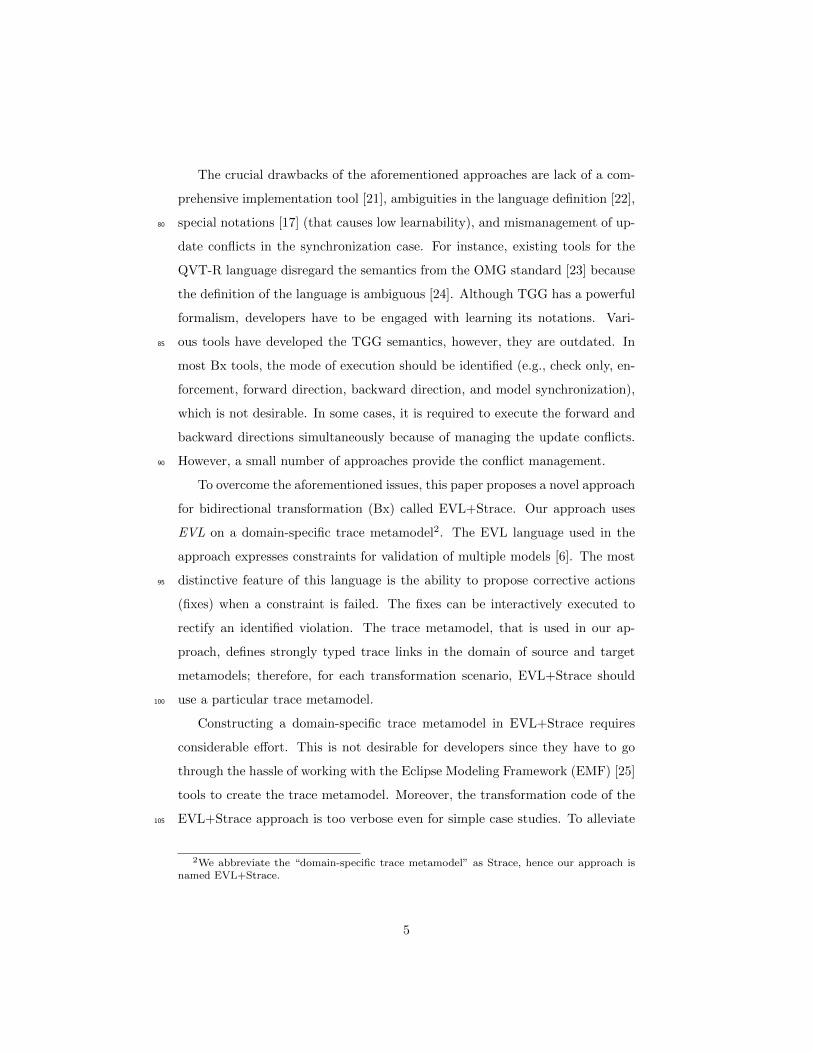
ample. Figure 1 presents two versions of metamodels for storing the information
about publications in a simple way. The source metamodel includes Publica-155
tionTool1 acting as the root, which consists of a set of Publications. The
root of the target metamodel is PublicationTool2, which contains a number of
Publications. Each Publication in the source has a title and a publisher;
however, in the target metamodel, Publication is described by a single name
attribute. The kind of Publication in the first metamodel is represented by160
defining a reference to an instance of the Kind meta-class. In the second meta-
model, the kind attribute is responsible to present this concept.
7

(a) Source metamodel (b) Target metamodel
Figure 1: The source and target metamodels of the running example (adapted from [29])
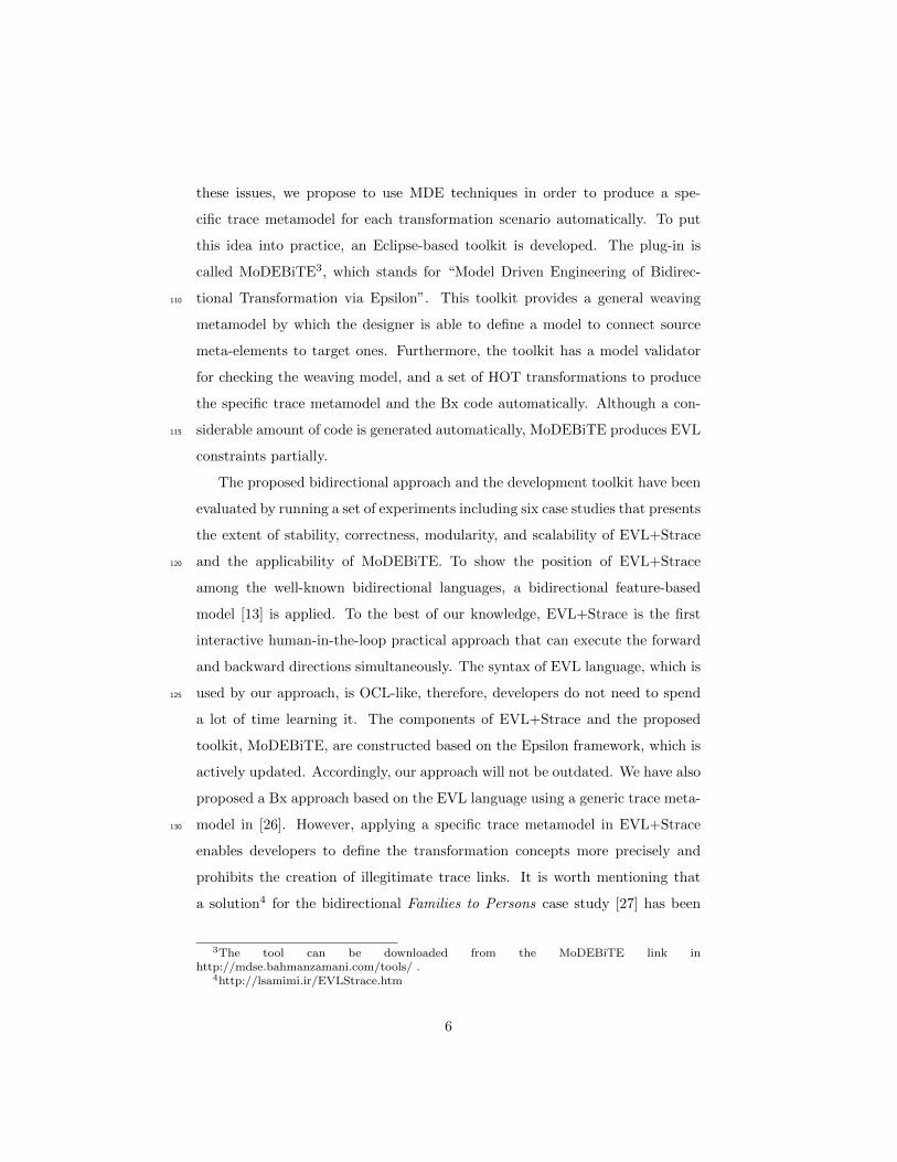
Example 1. Figure 2 presents an example of two consistent models that con-
form to the metamodels in Figure 1. The left model (Figure 2a) is an instance
of the source metamodel with three Publication objects and two elements of165
Kind. Likewise, the right model (Figure 2b) consists of three instances of the
target Publication meta-class.
(a) Source model (b) Target model
Figure 2: An example of the source and target models for the running example
8
The Bx description between metamodels is explained in the following:
• The Bx should specify a bijective mapping between Publications in both
systems. Matched Publications should present the same data. The name170
of a target publication should be equal to the publisher of the corre-
sponding publication (in the source) followed by its title, separated by
a dash symbol. Moreover, if a source Publication instance is linked to
a Kind instance with a particular name, the kind attribute of the corre-
sponding target Publication object must be set to that name. It is worth175
mentioning that the Kind.name attribute is an identifier. Consequently,
having two instances of Kind with the same name is illegal.
• In the synchronization case, if the value of one (or more) attribute from
the source or target model is modified, it will be propagated to the other
model. For instance, if the user changes the value of title or publisher180
from a publication in the source model, the transformation should update
the name attribute of the corresponding publication in the target model,
and vice versa.
• If the name of a Kind instance is modified manually, the kind attribute of
all the corresponding target Publication instances must be updated. In185
the other side, if the user alters the kind attribute of a target Publication
object, the Bx should change the name attribute of the corresponding Kind
object and all kind attributes of the other related target Publication
objects. Note that, most bidirectional approaches cannot provide this
case (changing the other related target publications).190
• Manual deletion of a Publication instance from the source model should
result in removing the corresponding Publication instance of the target
model, and vice versa. If the Kind object is not referenced by any source
Publication object, it will also be removed. If the user deletes a Kind
instance, all corresponding target Publication objects and all related195
source Publication instances should be deleted.
9

3. EVL+Strace : An Epsilon-based Bx approach
The EVL+Strace approach proposes to use the EVL language [6] on a
domain-specific trace metamodel for a bidirectional transformation. To describe
our approach, we first present the required artifacts of the approach for defining200
a bidirectional transformation, which are the domain-specific trace metamodel
(Section 3.1) and the EVL+Strace transformation code (Section 3.2). After
introducing the EVL+Strace artifacts, the high-level view of EVL+Strace is
described in Section 3.3, which elaborates on the idea behind the proposed ap-
proach. Finally, in Section 3.4, we illustrate how the artifacts of the EVL+Strace205
transformation can be automatically produced by the MoDEBiTE toolkit. The
motivating example of the previous section is used to explain each part of the
mentioned sections.
3.1. Domain-specific trace metamodel
A domain-specific trace metamodel consists of strongly typed trace links.210
Each trace link connects some identified trace link ends. Trace link ends refer
to source/target elements by defining a type reference. It is noteworthy that the
link ends are also strongly typed. With the aid of the specific trace metamodel,
defining invalid links is prohibited. Figure 3 represents the domain-specific trace
model, which is placed between the consistent source and target models.215
The trace model, in Figure 3, contains four trace links, including l1 with
PubTool12PubTool2TraceLink type and l2, l3, and l4 that are defined from
PublicationKind2PublicationTraceLink type. The link l1 connects the root
trace link ends, i.e., r1 with PublicationTool1SourceEnd type and r1′ instance
of PublicationTool2TargetEnd meta-class. The other three trace links con-220
nect two source ends, i.e., PublicationSourceEnd and KindSourceEnd, with a
single PublicationTargetEnd instance. This type of trace link is an example
of many-to-one relation. Each PublicationSourceEnd element refers to a
Publication element and preserves the same typed features. For example, pt1
keeps two attributes title and publisher with values ‘PofEAA’ and ‘AW’.225
10

Figure 3: Source, trace, and target model instances in the EVL+Strace approach
The instance pt1 has also a reference to kt1:KindSourceEnd , which corresponds
to the reference from p1:Publication to k1:Kind in the source. Note that, the
references from r1:PublicationTool1SourceEnd to the other source end objects
are not presented for the sake of simplicity. Similarly, for each Publication
instance in the target, a PublicationTargetEnd element exists in the trace,230
which keeps the corresponding information.
EVL+Strace can detect independent updates on the source and target mod-
els by checking the information of the trace model. The atomic updates are
element additions, removals, relocations, and attribute value modifications [12].
Figure 4 shows some examples of these atomic operations, which are referred to235
by their numbers in the following.
Numbers 1 and 6 show element additions in the source and target models,
respectively. Numbers 2 demonstrates an attribute value modification in the
source and number 5 indicates a modification in the target. Number 3 displays
an example of element relocation. Finally, number 4 illustrates an instance of240
element deletion.
EVL+Strace recognizes an element addition, if that element does not have
11
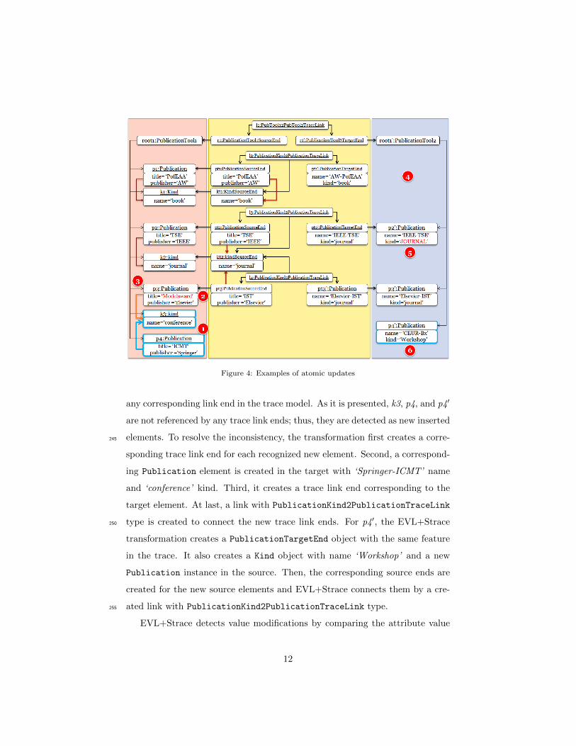
Figure 4: Examples of atomic updates
any corresponding link end in the trace model. As it is presented, k3, p4, and p4′
are not referenced by any trace link ends; thus, they are detected as new inserted
elements. To resolve the inconsistency, the transformation first creates a corre-245
sponding trace link end for each recognized new element. Second, a correspond-
ing Publication element is created in the target with ‘Springer-ICMT’ name
and ‘conference’ kind. Third, it creates a trace link end corresponding to the
target element. At last, a link with PublicationKind2PublicationTraceLink
type is created to connect the new trace link ends. For p4′, the EVL+Strace250
transformation creates a PublicationTargetEnd object with the same feature
in the trace. It also creates a Kind object with name ‘Workshop’ and a new
Publication instance in the source. Then, the corresponding source ends are
created for the new source elements and EVL+Strace connects them by a cre-
ated link with PublicationKind2PublicationTraceLink type.255
EVL+Strace detects value modifications by comparing the attribute value
12
of the source (target) elements to the corresponding values in the trace. For
example, when it compares the title value of pt3 to the corresponding value
of p3 in the source, it recognizes a modification. The trace title keeps the
old information and the source title shows the new value. Consequently, the260
approach updates the value of the trace title, and changes the names of pt3′
and p3′ in the trace and target models, respectively. The kind value of p2′
and its corresponding, pt2′, is not equal, so EVL+Strace distinguishes that the
value ‘journal’ should be modified to ‘JOURNAL’. To fix this violation, the
kind value of pt2′, the name value of kt2 in the trace, and the name value of265
k2 should be updated. Note that, if p3 in the source referred to k2 like before,
EVL+Strace would update the kind value of its corresponding target element,
i.e., p3′, to ‘JOURNAL’ value.
The approach distinguishes an element relocation by comparing the corre-
sponding references in the trace and source/target models. For instance, since270
there is a reference from pt3 to kt2 in the trace, EVL+Strace expects a corre-
sponding reference between p3 and k2 in the source. However, the expectation
is violated, and the reference is pointed to k3. In this case, a KindSourceEnd
object is created in the trace for the k3, if it has not been created before that,
and l4 refers to the new KindSourceEnd object with ‘conference’ value instead275
of referring to kt2. The kind value of pt3′ in the trace and p3′ in the target is
also updated.
An element removal in the source/target models is recognized when the
type reference of a trace link end is not pointed to the source or target model
elements. Figure 4 shows that pt1′ does not refer to any Publication element280
in the target. To restore the consistency, the pt1′ object, the l2 trace link, its
source ends, i.e., pt1 and kt1, and the corresponding source elements (p1 and
k1 ) will be deleted.
3.2. EVL+Strace transformation code
The transformation code in EVL+Strace comprises two main parts: EOL285
operations and EVL constraints. The EOL operations provide readable and
13
modularized transformation code. The main parts of the EVL+Strace code are
explained in the following.
EOL operations. The EOL operations are divided into five groups: Auxiliary,
Delete, Modify, Move, and Add operations. The second, third, and last groups290
have two types, i.e., Check and Fix. Auxiliary operations are used by other EOL
operations which compute values, get or find objects, and set the references. A
Delete operation checks if an object is removed, or in some cases, deletes an
object from models. Modify operations either identify whether an attribute
value is modified, or propagate the changed value to the attributes of other295
objects. Move operations change the references to the moved objects. Finally,
Add operations investigate if a source/target object is manually added, or in
some cases, they insert new elements in models, and add a trace link with some
link ends. Example 2 presents a sample code of two EOL operations.
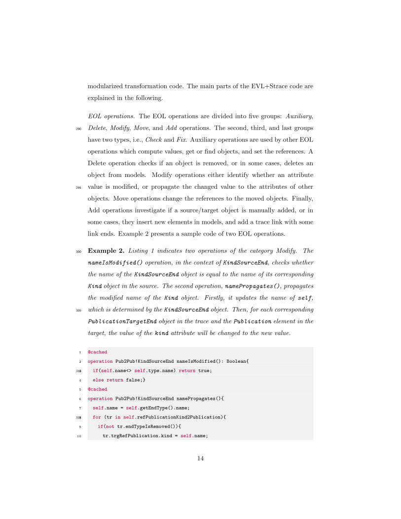
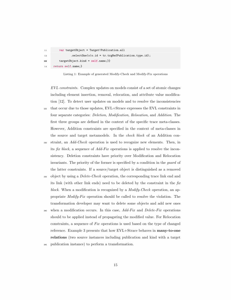
Example 2. Listing 1 indicates two operations of the category Modify. The300
nameIsModified() operation, in the context of KindSourceEnd, checks whether
the name of the KindSourceEnd object is equal to the name of its corresponding
Kind object in the source. The second operation, namePropagates(), propagates
the modified name of the Kind object. Firstly, it updates the name of self,
which is determined by the KindSourceEnd object. Then, for each corresponding305
PublicationTargetEnd object in the trace and the Publication element in the
target, the value of the kind attribute will be changed to the new value.
1 @cached
2 operation Pub2Pub!KindSourceEnd nameIsModified(): Boolean{
3 if(self.name<> self.type.name) return true;310
4 else return false;}
5 @cached
6 operation Pub2Pub!KindSourceEnd namePropagates(){
7 self.name = self.getEndType().name;
8 for (tr in self.refPublicationKind2Publication){315
9 if(not tr.endTypeIsRemoved()){
10 tr.trgRefPublication.kind = self.name;
14
11 var targetObject = Target!Publication.all
12 .selectOne(o|o.id = tr.trgRefPublication.type.id);
13 targetObject.kind = self.name;}}320
14 return self.name;}
Listing 1: Example of generated Modify-Check and Modify-Fix operations
EVL constraints. Complex updates on models consist of a set of atomic changes
including element insertion, removal, relocation, and attribute value modifica-
tion [12]. To detect user updates on models and to resolve the inconsistencies
that occur due to those updates, EVL+Strace expresses the EVL constraints in325
four separate categories: Deletion, Modification, Relocation, and Addition. The
first three groups are defined in the context of the specific trace meta-classes.
However, Addition constraints are specified in the context of meta-classes in
the source and target metamodels. In the check block of an Addition con-
straint, an Add-Check operation is used to recognize new elements. Then, in330
its fix block, a sequence of Add-Fix operations is applied to resolve the incon-
sistency. Deletion constraints have priority over Modification and Relocation
invariants. The priority of the former is specified by a condition in the guard of
the latter constraints. If a source/target object is distinguished as a removed
object by using a Delete-Check operation, the corresponding trace link end and335
its link (with other link ends) need to be deleted by the constraint in the fix
block. When a modification is recognized by a Modify-Check operation, an ap-
propriate Modify-Fix operation should be called to resolve the violation. The
transformation developer may want to delete some objects and add new ones
when a modification occurs. In this case, Add-Fix and Delete-Fix operations340
should to be applied instead of propagating the modified value. For Relocation
constraints, a sequence of Fix operations is used based on the type of changed
reference. Example 3 presents that how EVL+Strace behaves in many-to-one
relations (two source instances including publication and kind with a target
publication instance) to perform a transformation.345
15
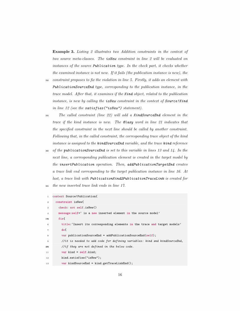
Example 3. Listing 2 illustrates two Addition constraints in the context of
two source meta-classes. The isNew constraint in line 2 will be evaluated on
instances of the source Publication type. In the check part, it checks whether
the examined instance is not new. If it fails (the publication instance is new), the
constraint proposes to fix the violation in line 5. Firstly, it adds an element with350
PublicationSourceEnd type, corresponding to the publication instance, in the
trace model. After that, it examines if the Kind object, related to the publication
instance, is new by calling the isNew constraint in the context of Source!Kind
in line 12 (see the satisfies("isNew") statement).
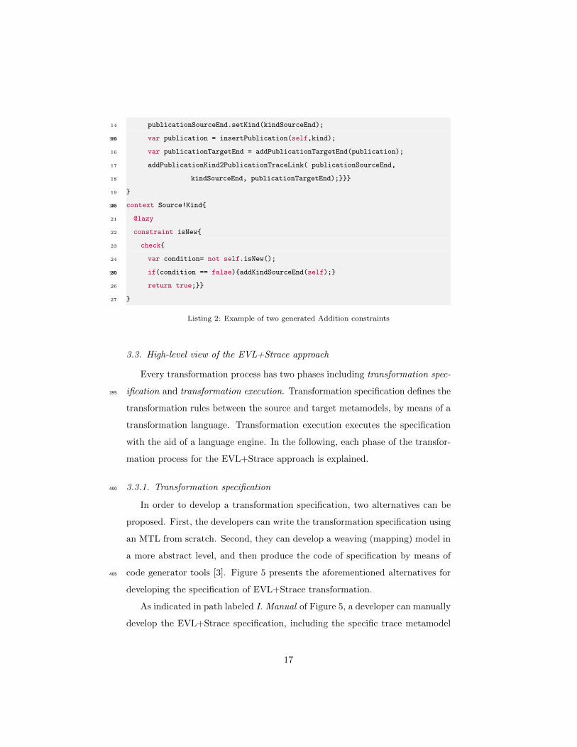
The called constraint (line 22) will add a KindSourceEnd element in the355
trace if the kind instance is new. The @lazy word in line 21 indicates that
the specified constraint in the next line should be called by another constraint.
Following that, in the called constraint, the corresponding trace object of the kind
instance is assigned to the kindSourceEnd variable, and the trace kind reference
of the publicationSourceEnd is set to this variable in lines 13 and 14. In the360
next line, a corresponding publication element is created in the target model by
the insertPublication operation. Then, addPublicationTargetEnd creates
a trace link end corresponding to the target publication instance in line 16. At
last, a trace link with PublicationKind2PublicationTraceLink is created for
the new inserted trace link ends in line 17.365
1 context Source!Publication{
2 constraint isNew{
3 check: not self.isNew()
4 message:self+‘ is a new inserted element in the source model’
5 fix{370
6 title:‘Insert its corresponding elements in the trace and target models’
7 do{
8 var publicationSourceEnd = addPublicationSourceEnd(self);
9 //it is needed to add code for defining variables: kind and kindSourceEnd,
10 //if they are not defined in the below code.375
11 var kind = self.kind;
12 kind.satisfies("isNew");
13 var kindSourceEnd = kind.getTraceLinkEnd();
16
14 publicationSourceEnd.setKind(kindSourceEnd);
15 var publication = insertPublication(self,kind);380
16 var publicationTargetEnd = addPublicationTargetEnd(publication);
17 addPublicationKind2PublicationTraceLink( publicationSourceEnd,
18 kindSourceEnd, publicationTargetEnd);}}}
19 }
20 context Source!Kind{385
21 @lazy
22 constraint isNew{
23 check{
24 var condition= not self.isNew();
25 if(condition == false){addKindSourceEnd(self);}390
26 return true;}}
27 }
Listing 2: Example of two generated Addition constraints
3.3. High-level view of the EVL+Strace approach
Every transformation process has two phases including transformation spec-
ification and transformation execution. Transformation specification defines the395
transformation rules between the source and target metamodels, by means of a
transformation language. Transformation execution executes the specification
with the aid of a language engine. In the following, each phase of the transfor-
mation process for the EVL+Strace approach is explained.
3.3.1. Transformation specification400
In order to develop a transformation specification, two alternatives can be
proposed. First, the developers can write the transformation specification using
an MTL from scratch. Second, they can develop a weaving (mapping) model in
a more abstract level, and then produce the code of specification by means of
code generator tools [3]. Figure 5 presents the aforementioned alternatives for405
developing the specification of EVL+Strace transformation.
As indicated in path labeled I. Manual of Figure 5, a developer can manually
develop the EVL+Strace specification, including the specific trace metamodel
17
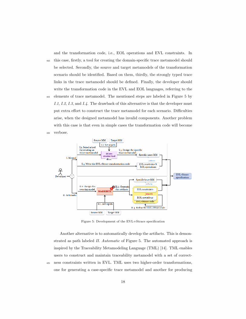
and the transformation code, i.e., EOL operations and EVL constraints. In
this case, firstly, a tool for creating the domain-specific trace metamodel should410
be selected. Secondly, the source and target metamodels of the transformation
scenario should be identified. Based on them, thirdly, the strongly typed trace
links in the trace metamodel should be defined. Finally, the developer should
write the transformation code in the EVL and EOL languages, referring to the
elements of trace metamodel. The mentioned steps are labeled in Figure 5 by415
I.1, I.2, I.3, and I.4. The drawback of this alternative is that the developer must
put extra effort to construct the trace metamodel for each scenario. Difficulties
arise, when the designed metamodel has invalid components. Another problem
with this case is that even in simple cases the transformation code will become
verbose.420
Figure 5: Development of the EVL+Strace specification
Another alternative is to automatically develop the artifacts. This is demon-
strated as path labeled II. Automatic of Figure 5. The automated approach is
inspired by the Traceability Metamodeling Language (TML) [14]. TML enables
users to construct and maintain traceability metamodel with a set of correct-
ness constraints written in EVL. TML uses two higher-order transformations,425
one for generating a case-specific trace metamodel and another for producing
18
EVL constraints as semantic properties of the trace metamodel. Due to the fact
that TML is designed for various purposes in the context of the MDE traceabil-
ity [31], we particularly focus on specifying Bx based on the EVL capabilities in
this work. For this reason, instead of using TML, we develop an Eclipse-based430
toolkit, called MoDEBiTE, by proposing a new weaving metamodel. With the
aid of this metamodel, it is possible to generate more detailed and precise EOL
operations and EVL constraints for the purpose of bidirectionality. As pre-
sented in Figure 5, this alternative requires four main activities to make the
specification ready to use, as per following:435
II.1 identifying input metamodels for MoDEBiTE, i.e., the source and target
metamodels of the transformation scenario.
II.2 designing a model to weave the source and target meta-elements.
II.3 generating outputs including specific trace metamodel and EVL+Strace
code (EOL operations and EVL constraints).440
II.4 refining the generated code since the output code of MoDEBiTE is not
totally executable in some transformation scenarios.
After developing the EVL+Strace artifacts, either automatically or manually,
the EVL+Strace Specification will be provided to be used for the bidirectional
transformation.445
3.3.2. Transformation execution
The EVL engine should execute the specification to accomplish the transfor-
mation process. The execution phase for EVL+Strace is presented in Figure 6.
Three models of the source, trace, and target are synchronized in this phase that
should conform to their respective metamodels. The conformity of a model to its450
metamodel is demonstrated by gray dotted line in Figure 6. Both components
of the EVL+Strace specification refer to the source and target metamodels, that
is depicted by blue dashed arrows.
19
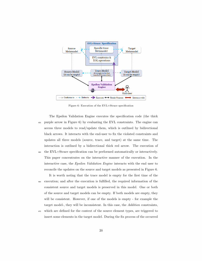
Figure 6: Execution of the EVL+Strace specification
The Epsilon Validation Engine executes the specification code (the thick
purple arrow in Figure 6) by evaluating the EVL constraints. The engine can455
access three models to read/update them, which is outlined by bidirectional
black arrows. It interacts with the end-user to fix the violated constraints and
updates all three models (source, trace, and target) at the same time. The
interaction is outlined by a bidirectional thick red arrow. The execution of
the EVL+Strace specification can be performed automatically or interactively.460
This paper concentrates on the interactive manner of the execution. In the
interactive case, the Epsilon Validation Engine interacts with the end user to
reconcile the updates on the source and target models as presented in Figure 6.
It is worth noting that the trace model is empty for the first time of the
execution; and after the execution is fulfilled, the required information of the465
consistent source and target models is preserved in this model. One or both
of the source and target models can be empty. If both models are empty, they
will be consistent. However, if one of the models is empty - for example the
target model-, they will be inconsistent. In this case, the Addition constraints,
which are defined for the context of the source element types, are triggered to470
insert some elements in the target model. During the fix process of the occurred
20
inconsistency between the source and target models, the trace links are created
in the trace model. In the next round of the execution, if one (or both) of the
source/target models are updated and the inter-model consistency is violated,
the original information will be extracted from trace to recognize the differences475
between old and new information.
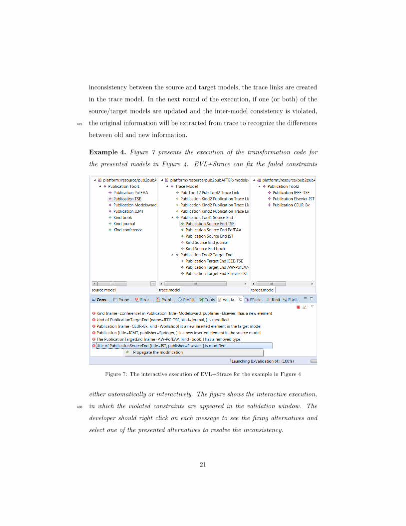
Example 4. Figure 7 presents the execution of the transformation code for
the presented models in Figure 4. EVL+Strace can fix the failed constraints
Figure 7: The interactive execution of EVL+Strace for the example in Figure 4
either automatically or interactively. The figure shows the interactive execution,
in which the violated constraints are appeared in the validation window. The480
developer should right click on each message to see the fixing alternatives and
select one of the presented alternatives to resolve the inconsistency.
21
3.4. MoDEBiTE: a toolkit to develop the EVL+Strace code
As it was explained earlier, the EVL+Strace approach preserves the strongly
typed information of the source and target in a trace model conforming to the485
domain-specific trace metamodel. Additionally, it specifies the EVL constraints
in the context of strongly typed trace elements. However, developing Bx via
EVL+Strace makes the transformation code too verbose and complex. This
might become even more complicated when it deals with the manipulation of
trace elements. To overcome this issue and reduce the risk of coding errors, the490
MDE principles are applied for the development of EVL+Strace. This section
presents the technical principles of MoDEBiTE, which generates Bx code by
means of Epsilon.
[yes]
[no]
Is valid?
2. Create an empty
weaving model in the
ModeLink editor
3. Design the weaving
model
The weaving model
1. Upload source/
target Metamodels
Read the weaving
model
6. First
M2T HOT
7. Second
M2T HOT
5. M2M HOT
HTML
documents
EVL
constraints
8. Third
M2T HOT
EOL
operations
Specific trace
metamodel
9. Refine
Refined EVL
constraints
4. Validation
ArtifactStart Stop
Activity Condition Reads/
outputs
Control
flow
Figure 8: Workflow for developing a Bx using MoDEBiTE
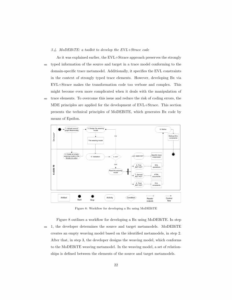
Figure 8 outlines a workflow for developing a Bx using MoDEBiTE. In step
1, the developer determines the source and target metamodels. MoDEBiTE495
creates an empty weaving model based on the identified metamodels, in step 2.
After that, in step 3, the developer designs the weaving model, which conforms
to the MoDEBiTE weaving metamodel. In the weaving model, a set of relation-
ships is defined between the elements of the source and target metamodels.
22
After designing the weaving model, step 4 of the workflow uses a validator to500
check the intra-model consistency of that model. Following the validation phase,
if the model is valid, a model to model HOT transforms the weaving model to a
domain-specific trace metamodel, in step 5. Thus, the trace links are specified
explicitly in the metamodel level, which were implicit in the weaving model.
MoDEBiTE provides three M2T HOTs to generate the transformation code505
and corresponding documents. The first HOT produces the EOL operations,
in step 6. The second transformation produces the EOL documents, as HTML
pages, making the operations convenient to use, in step 7. The third HOT, in
step 8, generates the bidirectional transformation constraints in EVL. In step
9, the generated EVL code should be refined to become executable. Example 5510
illustrates step 1 and step 2 of the MoDEBiTE workflow for the motivating
example in Section 2.
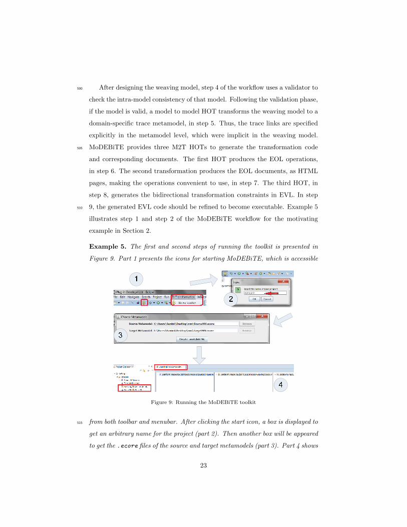
Example 5. The first and second steps of running the toolkit is presented in
Figure 9. Part 1 presents the icons for starting MoDEBiTE, which is accessible
Figure 9: Running the MoDEBiTE toolkit
from both toolbar and menubar. After clicking the start icon, a box is displayed to515
get an arbitrary name for the project (part 2). Then another box will be appeared
to get the .ecore files of the source and target metamodels (part 3). Part 4 shows
23
that the ModeLink editor will be opened automatically for developers to design
the weaving model. The source metamodel is placed at the left, and the target
is located at the right side of the editor. The developer will design the weaving520
model between two metamodels in order to weave the source and target elements.
In the following, the remaining steps (steps 3-9) of the workflow for develop-
ing the EVL+Strace code by means of MoDEBiTE are explained in details. For
each step, we provide an example based on the motivating example explained
in Section 2.525
3.4.1. Design the weaving model
The Developer should design the weaving model conforming to the MoDEB-
iTE weaving metamodel (general trace metamodel), which provides a number
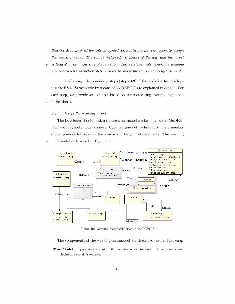
of components for weaving the source and target meta-elements. The weaving
metamodel is depicted in Figure 10.530
Figure 10: Weaving metamodel used in MoDEBiTE
The components of the weaving metamodel are described, as per following:
TraceModel: Represents the root of the weaving model instance. It has a name and
includes a set of TraceLinks.
24
TraceLink: Indicates the links that each contains a number of source/target link ends.
TraceLinkEnd: Refers to a source/target meta-class through the type reference. That is535
to say, it is responsible for preserving the same features (but not all) of that source/tar-
get meta-class. The upperBoundOfTraceLink attribute with default value 1 identifies
the maximum number of TraceLinks, which refer to this type of TraceLinkEnd. If the
isEndPoint value is true, the TraceLinkEnd object in the EVL+Strace will be respon-
sible for creating other link end objects. The isAbstract attribute specifies if it is an540
abstract trace link end or not. The ofTypeOnly attribute determines that the type
object should be a particular element or it can be the subtypes of that element. If the
forAll attribute is set to true, it will define that a corresponding link end should exist
for all source/target objects with the specified type. The lowerBound and upperBound
attributes defines the minimum and maximum number of elements that the owner link545
can refer to. Each TraceLinkEnd may contain a number of TraceFeatureEnds.
TraceFeatureEnd: Expresses a feature from source or target metamodels, which can be
defined as an Attribute or a Reference. The isKey attribute identifies whether this
feature is a key property or not. (The concept isKey is inspired by the QVT-R lan-
guage [16].)550
Attribute: Refers to a source/target meta-attribute through the featureType reference.
Moreover, it specifies a single operation to demonstrate how its value can be computed.
AttributeOperation: Is an abstract class that defines an operation for computing the value
of the owner Attribute. It has two kinds including AttributeCopy and ComplexOperation.
AttributeCopy: Defines an operation that copies the input parameter to the owner Attribute.555
ComplexOperation: Provides a computing operation for each Attribute value. It has a
name and a body. The developer should specify the body in the EOL language based on
the name of referred Parameters.
Parameter: Defines a parameter for each SetAttributeOperation. It has a name and refers
to a TraceFeatureEnd.560
Reference: Corresponds to the source/target meta-reference by specifying the featureType
reference. It refers to a TraceLinkEnd through the toRef reference. The TraceLinkEnd
referenced by the Reference corresponds to the meta-class, which is referenced by the
featureType of the Reference. The opposite reference defines an opposite for this
Reference. It may have a SetReference operation if it is participated in a Reference565
to Reference transformation.
25

SetReference: Implements a transformation between two References. If the container
(from type of TraceLinkEnd) of its own Reference and the par reference are weaved by
the same TraceLink, the isInverse attribute is set to false, otherwise it is set to true.
Example 6. We design a model to weave the source and target metamodels570
of the motivating example (Section 2). Figure 11 displays this weaving model.
The ‘SMM2TMM’ name is set for the element TraceModel. Two TraceLinks
Figure 11: Designing MoDEBiTE weaving model in ModeLink Editor
are specified as the children of TraceModel including ‘Pubtool12Pubtool2’ and
‘PublicationKind2Publication’ trace links. The first one connects PublicationTool1
TraceLinkEnd to PublicationTool2 TraceLinkEnd. The type reference of the575
first link end refers to the PublicationTool1 meta-class in the source and the
second link end refers to the PublicationTool2 meta-class of the target. Two
References are defined for the source link end named pubs and kinds, which
refer to the corresponding meta-references in the source metamodel. Likewise, a
Reference, named pubs, is specified for the target TraceLinkEnd referring to the580
26
target pubs meta-reference as its featureType. The PublicationKind2Publication
TraceLink has two sources including Publication and Kind TraceLinkEnds and
one target end referring to the target Publication meta-class. The source Publica-
tion TraceLinkEnd defines two trace Attributes referring to the title and pub-
lisher meta-attributes and a Reference specifying the kind meta-reference. The585
Kind TraceLinkEnd has a name Attribute defining the name meta-attribute
of the Kind source meta-class. The target Publication TraceLinkEnd specifies
two Attributes including name and kind referring to the corresponding meta-
attributes in the target. The feature isEndPoint of the Kind TraceLinkEnd is
set to false, which means that the Kind trace link end will not be created inde-590
pendently. Furthermore, the isKey property of the name Attribute in this link
end is changed to true because the Kind.name attribute is unique based on the
description of the transformation in Section 2.
After designing a model in the ModeLink editor, all changes that are made by
the developer are saved in the weavingModel.xmi file and MoDEBiTE provides595
five possible activities on this file. The first activity is the model validation.
The toolkit generates a specific trace metamodel in the second activity. After
that, EOL operations and EOL documentations can be produced as the third
and fourth activities, respectively. At last, MoDEBiTE generates the EVL Bx
code as the fifth activity. In the following, these activities are explained on the600
running example.
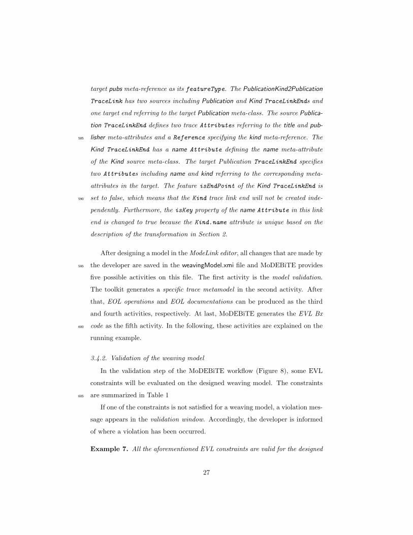
3.4.2. Validation of the weaving model
In the validation step of the MoDEBiTE workflow (Figure 8), some EVL
constraints will be evaluated on the designed weaving model. The constraints
are summarized in Table 1605
If one of the constraints is not satisfied for a weaving model, a violation mes-
sage appears in the validation window. Accordingly, the developer is informed
of where a violation has been occurred.
Example 7. All the aforementioned EVL constraints are valid for the designed
27
Table 1: Constraints used in the validation step of the MoDEBiTE workflow
1 The name of TraceModel cannot be empty.2 The name of TraceModel should start with a letter.3 At least one source/target TraceLinkEnd must be specified for a TraceLink.4 The type of TraceLinkEnd must be specified.5 The type of source (target) TraceLinkEnd must refer to one of the source (target)
meta-classes.6 The featureType of TraceFeatureEnd must be specified.7 The type toRef reference must be specified.8 The featureType of source (target) trace Reference must refer to a source (target)
meta-reference.9 The featureType of source (target) trace Attribute must refer to a source (target)
meta-attribute.10 All defined parameters for computing the Attribute of the source (target) end must
be selected from the features of target (source) ends.11 All defined parameters for computing the Attribute of the source (target) end must
be selected from its own TraceLink.12 The name of ComplexOperation cannot be empty.13 The body of ComplexOperation cannot be empty.14 The parRef reference of Parameter must be specified.15 The name of Parameter must be specified.
model of the example in Figure 11.610
3.4.3. M2M HOT (Domain-specific trace metamodeling)
The M2M higher-order transformation of the MoDEBiTE workflow is de-
scribed in this section. Domain Specific Metamodeling Language (DSM2L) [32]
is a metamodeling technique, in which a domain specific metamodel is generated
from a model. MoDEBiTE uses this technique in the M2M higher-order trans-615
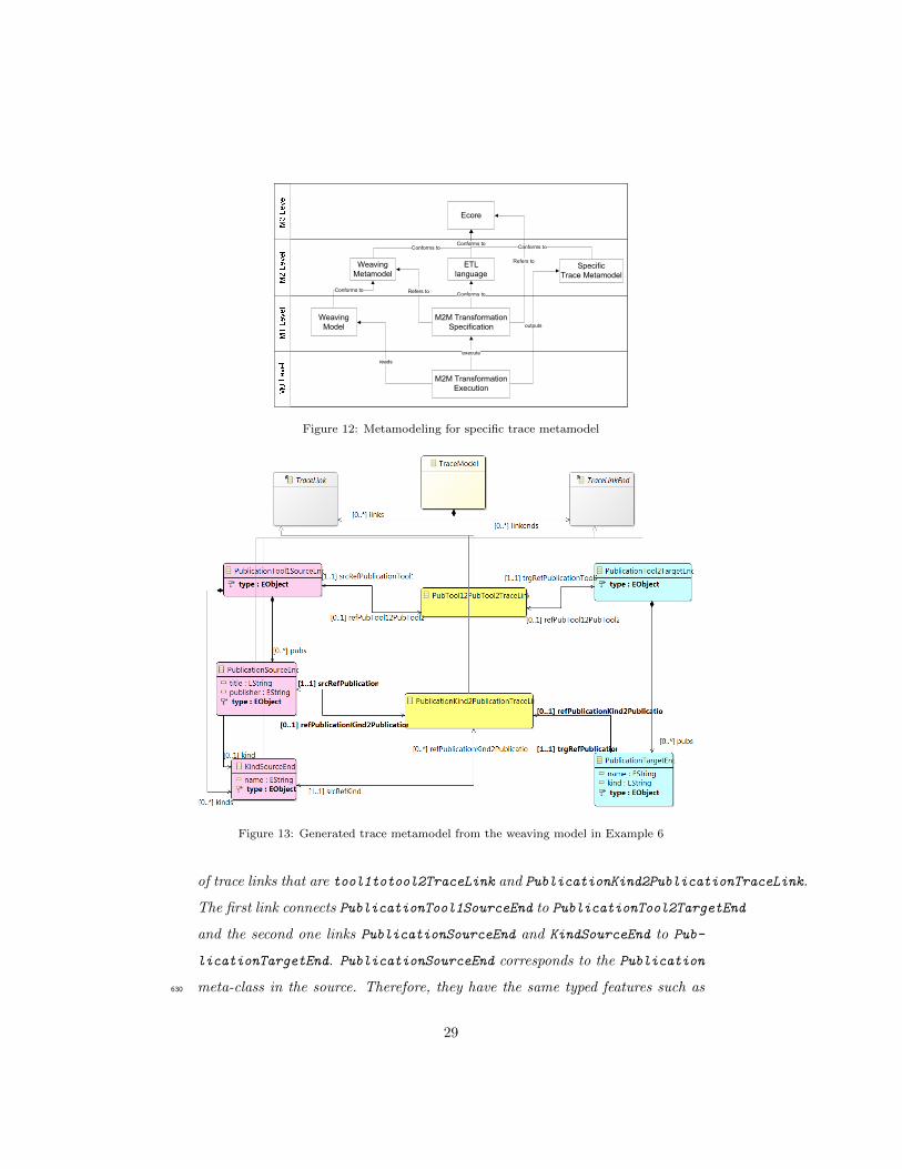
formation to produce a domain-specific trace metamodel. Figure 12 demon-
strates the MoDEBiTE process of DSM2L. The specification of the M2M trans-
formation is written in ETL, which considers the weaving metamodel as the
source and the ECore meta-metamodel as the target. It is worth noting that
the target of the specification is placed at the third layer (M3) of three-level620
metamodeling architecture. Hence, the generated output from the execution of
the transformation is placed at the second layer (M2), called the Specific Trace
metamodel.
Example 8. The generated specific trace metamodel from the weaving model of
the running example is demonstrated in Figure 13. The metamodel has two kinds625
28
Metamodeling of Specific Trace Metamodel
Ecore
Weaving
MetamodelSpecific
Trace Metamodel
Weaving
Model
M2M Transformation
Specification
Conforms to
Conforms to
ETL
language
Conforms to
M2M Transformation
Execution
execute
reads
outputs
Conforms toConforms to
Refers to
Refers to
Figure 12: Metamodeling for specific trace metamodel
Figure 13: Generated trace metamodel from the weaving model in Example 6
of trace links that are tool1totool2TraceLink and PublicationKind2PublicationTraceLink.
The first link connects PublicationTool1SourceEnd to PublicationTool2TargetEnd
and the second one links PublicationSourceEnd and KindSourceEnd to Pub-
licationTargetEnd. PublicationSourceEnd corresponds to the Publication
meta-class in the source. Therefore, they have the same typed features such as630
29
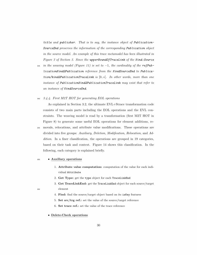
title and publisher. That is to say, the instance object of Publication-
SourceEnd preserves the information of the corresponding Publication object
in the source model. An example of this trace metamodel has been illustrated in
Figure 3 of Section 3. Since the upperBoundOfTraceLink of the Kind:Source
in the weaving model (Figure 11) is set to −1, the cardinality of the refPub-635
licationKind2Publication reference from the KindSourceEnd to Publica-
tion/kind2PublicationTraceLink is [0..∗]. In other words, more than one
instance of PublicationKind2PublicationTraceLink may exist that refer to
an instance of KindSourceEnd.
3.4.4. First M2T HOT for generating EOL operations640
As explained in Section 3.2, the ultimate EVL+Strace transformation code
consists of two main parts including the EOL operations and the EVL con-
straints. The weaving model is read by a transformation (first M2T HOT in
Figure 8) to generate some useful EOL operations for element additions, re-
movals, relocations, and attribute value modifications. These operations are645
divided into five groups: Auxiliary, Deletion, Modification, Relocation, and Ad-
dition. In a finer classification, the operations are grouped in 19 categories,
based on their task and context. Figure 14 shows this classification. In the
following, each category is explained briefly.
• Auxiliary operations650
1. Attribute value computation: computation of the value for each indi-
vidual Attribute
2. Get Type: get the type object for each TraceLinkEnd
3. Get TraceLinkEnd: get the TraceLinkEnd object for each source/target
element655
4. Find: find the source/target object based on its isKey features
5. Set src/trg ref.: set the value of the source/target reference
6. Set trace ref.: set the value of the trace reference
• Delete-Check operations
30
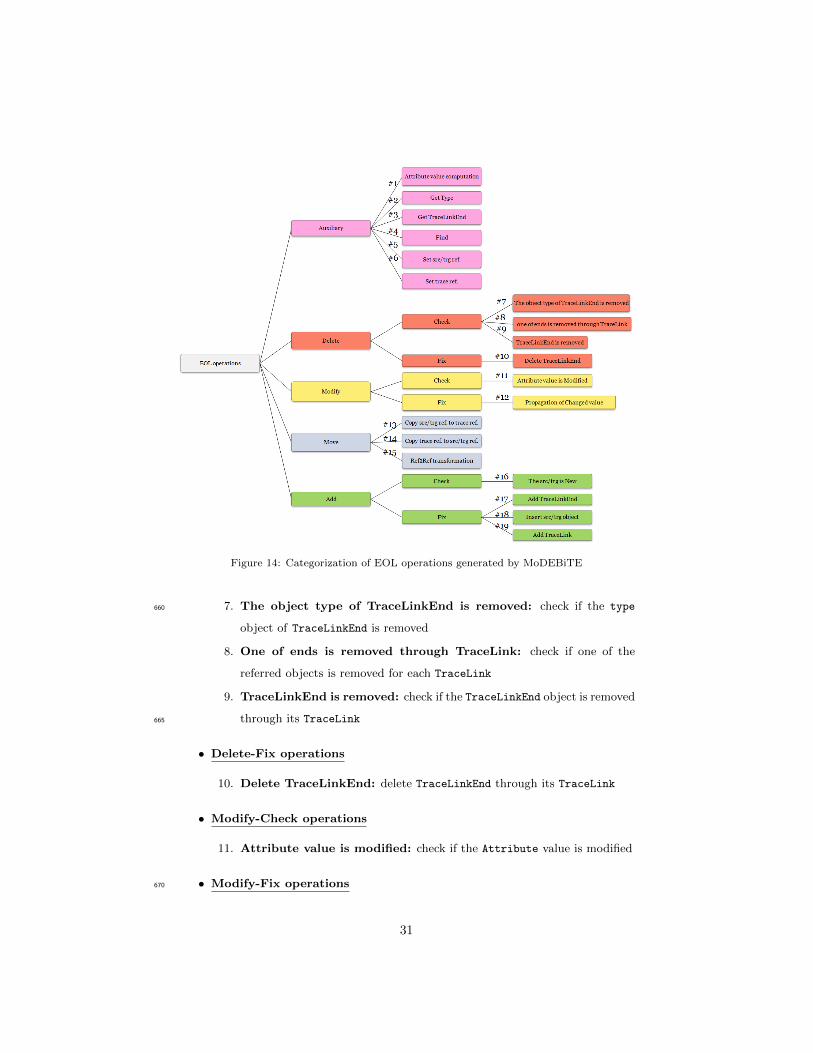
Figure 14: Categorization of EOL operations generated by MoDEBiTE
7. The object type of TraceLinkEnd is removed: check if the type660
object of TraceLinkEnd is removed
8. One of ends is removed through TraceLink: check if one of the
referred objects is removed for each TraceLink
9. TraceLinkEnd is removed: check if the TraceLinkEnd object is removed
through its TraceLink665
• Delete-Fix operations
10. Delete TraceLinkEnd: delete TraceLinkEnd through its TraceLink
• Modify-Check operations
11. Attribute value is modified: check if the Attribute value is modified
• Modify-Fix operations670
31
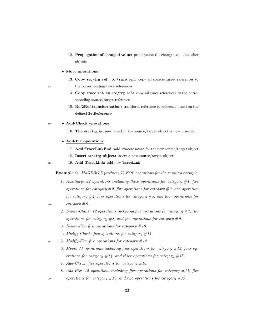
12. Propagation of changed value: propagation the changed value to other
objects
• Move operations
13. Copy src/trg ref. to trace ref.: copy all source/target references to
the corresponding trace references675
14. Copy trace ref. to src/trg ref.: copy all trace references to the corre-
sponding source/target references
15. Ref2Ref transformation: transform reference to reference based on the
defined SetReference
• Add-Check operations680
16. The src/trg is new: check if the source/target object is new inserted
• Add-Fix operations
17. Add TraceLinkEnd: add TraceLinkEnd for the new source/target object
18. Insert src/trg object: insert a new source/target object
19. Add TraceLink: add new TraceLink685
Example 9. MoDEBiTE produces 77 EOL operations for the running example:
1. Auxiliary: 22 operations including three operations for category #1, five
operations for category #2, five operations for category #3, one operation
for category #4, four operations for category #5, and four operations for
category #6.690
2. Delete-Check: 12 operations including five operations for category #7, two
operations for category #8, and five operations for category #9.
3. Delete-Fix: five operations for category #10.
4. Modify-Check: five operations for category #11.
5. Modify-Fix: five operations for category #12.695
6. Move: 11 operations including four operations for category #13, four op-
erations for category #14, and three operations for category #15.
7. Add-Check: five operations for category #16.
8. Add-Fix: 12 operations including five operations for category #17, five
operations for category #18, and two operations for category #19.700
32
3.4.5. Second M2T HOT for generating HTML documents
Each EOL operation has a simple procedure because it is responsible for
an atomic task. Since the number of these operations is high even in simple
transformation scenarios, MoDEBiTE produces an HTML page for each EOL
operation by executing an M2T HOT ( step 8 in Figure 8). It is worth mention-705
ing that the operations are not dependent to each other (except the Auxiliary
operations); thus, the system overload is low. The developer can access each
HTML page from the index.html page in order to read the signature and body of
the operations. The index page is generated by a separated EGL transformation,
which includes hyperlinks to HTML pages of EOL operations.710
Example 10. MoDEBiTE produces an HTML page for each EOL operation
for the running example. It also generates an index.html page that represents
the signatures of the operations and the hyperlinks to their HTML pages. As
explained in the example of Section 3.4.4, the number of EOL operations is 77;
therefore, considering the index page, 78 HTML pages are generated for the715
running example.
3.4.6. Third M2T HOT for generating EVL constraints
The last HOT of the MoDEBiTE workflow transforms the weaving model
into an EVL+Strace bidirectional transformation that expresses the Deletion,
Modification, Relocation, and Addition constraints. MoDEBiTE can automati-720
cally produce the Deletion and Modification constraints in most cases; however,
some parts of the Relocation and Addition constraints may not be generated
automatically. Although the generated code is incomplete to perform a bidi-
rectional transformation, MoDEBiTE automatically inserts comments in every
part of the code which requires the developer’s attention. The comments explain725
that what types of the EOL operations can be used to complete the Bx code.
Consequently, in the last step, the developer should complete the EVL+Strace
transformation code manually. When the revised Bx code is executed, it is able
to generate the trace model as well as the target (source) one from the source
(target) input model. The output code of the toolkit can be used as a synchro-730
33
nizer to propagate changes to the source/trace/target models at the same time.
In the following, various kinds of constraints that are generated by MoDEBiTE,
are explained.
• Deletion constraint (for each TraceLinkEnd): This type of constraint is
specified in the context of a defined link end and checks whether the735
corresponding source (target) object is deleted. It uses the EOL operations
of category #7 (Figure 14) in its check block. If an element removal is
recognized, the constraint deletes the corresponding trace link end object
and calls another Deletion constraint, which is defined for the related trace
link.740
• Deletion constraint (for each TraceLink): This type of constraint is de-
fined as a lazy invariant in the context of a specified trace link, which
means that it must be called by another constraint. Additionally, it is
responsible for deleting the self trace link and the trace link ends, which
are referenced by that trace link. Accordingly, it uses the EOL operations745
of category #9 in its check block and category #10 in its fix block.
• Modification constraint (for each trace attribute): This type of constraint
is specified in the context of trace link ends, which are the owners of
the trace Attributes. Since deletion takes precedence over modification
in EVL+Strace, MoDEBiTE defines a guard for each Modification con-750
straint. The guard states that the constraint is only evaluated on instances
of trace link ends with defined type reference. Therefore, the operations
of categories #7 and #8 are used in the guard block. The Modification
constraint checks if the defined attribute value is not equal to the corre-
sponding value in the source or target model, then the modification will755
be propagated in all affected features of source, trace, and target models.
It uses the EOL operations of category #11 in its check block and the
EOL operations of category #12 in the fix block.
• Relocation constraint (for each trace reference): If a trace reference refers
34
to a trace link end, but the corresponding source/target reference refers to760
an element, which is not corresponding to that trace link end, an element
relocation is recognized. The way of resolving the inconsistency is based
on the role of the reference in the transformation. For instance, if it is
participated in a Ref2Ref transformation, the fixing way is straightforward
by using the operations of categories #13, #14, and #15. However, in765
most cases, MoDEBiTE could not produce the code automatically.
• Addition constraint (for each source/target meta-class): This type of con-
straint is defined for checking whether a new source or target element is
inserted by means of the EOL operation of category #16. The constraint
may be defined in two cases based on the value of isEndPoint of the cor-770
responding TraceLinkEnd. If this attribute is set to true, the fix block of
the constraint is responsible for creating new objects in the other source/-
target model, and new objects of their corresponding trace end(s), and
trace link with the aid of the operations in categories #17, #18, and #19
(It may also uses the Move operations if needed). Otherwise, the fix block775
only adds a new trace link end for the new detected element in the trace
model by using the EOL operation in category #17.
In addition to the above constraints, the transformation code consists of a pre
block. In the pre block, the xmiIds feature is set to true for all three models
that causes to create an xmi unique identifier for each model element.780
Example 11. In step 8, MoDEBiTE automatically creates 22 constraints and
a pre block for the running example. Five of these constraints are responsible for
checking if a source/target element has been removed and then fix the occurred
violation. In their fix block, the owner link of that link end is notified of this dele-
tion and another constraint in the context of that TraceLink is called. MoDEB-785
iTE generates five lazy constraints in the context of PubTool12PubTool2TraceLink
and PublicationKind2PublicationTraceLink. It also produces five constraints
for checking and fixing the attribute value modifications. They are applied to
recognize the modification in title, publisher, name of Kind, name of target
35
Publication, and kind attributes. Two Relocation constraints are produced790
to distinguish a relocation in the kind reference of Publication in the source.
Depending on whether or not the referred Kind instance is new, two different
constraints are required. Moreover, MoDEBiTE produces five constraints for
checking if a new source/target element is manually inserted and then, fixing
the occurred violation by creating the corresponding trace or source/target ob-795
jects.
4. Evaluation
The evaluation of this paper is conducted in two parts. First, in an ex-
perimental assessment of Section 4.1, EVL+Strace and the proposed toolkit
are evaluated via six case studies. Then, we investigate the position of the800
EVL+Strace approach based on a well-known bidirectional feature-based clas-
sification in Section 4.2.
4.1. Experimental Assessment
The EVL+Strace approach and the MoDEBiTE toolkit have been evaluated
by running a set of experiments consisting of six case studies5. The case studies805
are explained in Section 4.1.1. Afterwards, in Section 4.1.2, the size of the
required specification of the transformation for each case is measured based on
the size of the trace metamodel, lines of code (LOC), number of operations,
and number of constraints. Section 4.1.3 will discuss the effort for developing
bx transformation for each case study, with or without the use of MoDEBiTE.810
Following that, Section 4.1.4 measures the modularity of the generated code for
each case to show the benefit of using MoDEBiTE. To present the correctness of
the EVL+Strace transformations, Section 4.1.5 provides several tests for each
case, with different features. Finally, Section 4.1.6 investigates the scalability of
the EVL+Strace transformation.815
5The implementation of EVL+Strace transformations can be downloaded fromhttp://www.lsamimi.ir/EVLStrace.htm
36
4.1.1. Case studies
The following case studies are selected in order to investigate various levels
of complexity and size of the transformation specification.
• Activity Diagram to MSProject (AD2MSP): This case is an exam-
ple of transforming behavioural diagrams, selected from the ATL transfor-820
mation cases6. The aim of this example is to produce an MS Project model
from a loop-free activity diagram. To bidirectionalize it, we consider it as
a view-update problem [10], in which the MS Project model is a view of
the activity diagram. To that end, in the backward transformation, the
simplest case of activity diagrams is generated from an MS Project model825
due to information loss. This case presents the behavior of EVL+Strace
facing the view-update problem.
• Migration of Bags (Bag2Bag): This example considers two equivalent
representations of bags [21]. In both representations, an object presents
each element with a value attribute. However, in the second version the830
value attribute is a key property and a multiplicity attribute keeps the
number of occurences for that value in the first model. This case is se-
lected because QVT-R cannot solve it with a single transformation speci-
fication [21]. In addition, TGG (eMoflon) cannot provide any solution for
it7. This case shows the expressiveness of EVL+Strace.835
• Publication to Publication (Pub2Pub): This case is presented as the
running example (see Section 2), which is an adapted version of publication
benchmark [29]. It is a deterministic case, which produces at most one
target model for each source model and vice versa.
• Families to Persons (Fam2Per): This case study is introduced in the840
ATL transformation Zoo8, which is a part of the “Usine Logicielle” project.
6https://www.eclipse.org/atl/usecases/UML2MsProject7http://bx-community.wikidot.com/examples:migrationofbags8http://www.eclipse.org/atl/documentation/basicExamples Patterns/
37
It is a well-known case study in the transformation community that is
used to educate the concepts of model transformations. A bidirectional
version of this case is proposed in TTC 2017 [27] rasing some challanges
for Bx tools such as information loss, flattening of hierarchies, and non-845
determinism.
• State Machine to Petri Nets (SM2PN): This example is introduced
for evaluating internal transformation DSLs [33]. We adapt it based on
the idea introduced by Rui Pais et al. [34]. State machines are used
to describe the discrete behaviour of the systems. Petri Nets is a well-850
known formalism of theoritical computer science. Both formalisms are
widely-used due to particular advantages. Implementation of this case
presents how EVL+Strace behaves when metamodels have inheritance
relationships between meta-classes. The most challenging part of this
case is to transform objects to associations and vice versa.855
• UML to MOF (UML2MOF): This case is part of the ATL transfor-
mation Zoo as it is intended to provide interoperability between UML and
MOF semantics. ATL provides two batch transformations for the forward9
and backward10 directions with 1500 LOC. Our task is to write a bidirec-
tional and incremental transformation to generate/synchronize MOF and860
UML models. This example considers as an industrial and scalable case.
4.1.2. Size of the transformation specifications
The transformation specification in EVL+Strace consists of two items: 1)
the specific trace metamodel, and 2) the EVL+Strace transformation code.
The size of former is measured using the number of EClasses, EReferences,865
and EAttributes. The size of latter is defined based on the number of EOL
operations, number of EVL constraints, and LOC.
9https://www.eclipse.org/atl/atlTransformations/UML2MOF/ExampleUML2MOF[v00.01].pdf10https://www.eclipse.org/atl/atlTransformations/MOF2UML/ExampleMOF2UML[v00.01].pdf
38
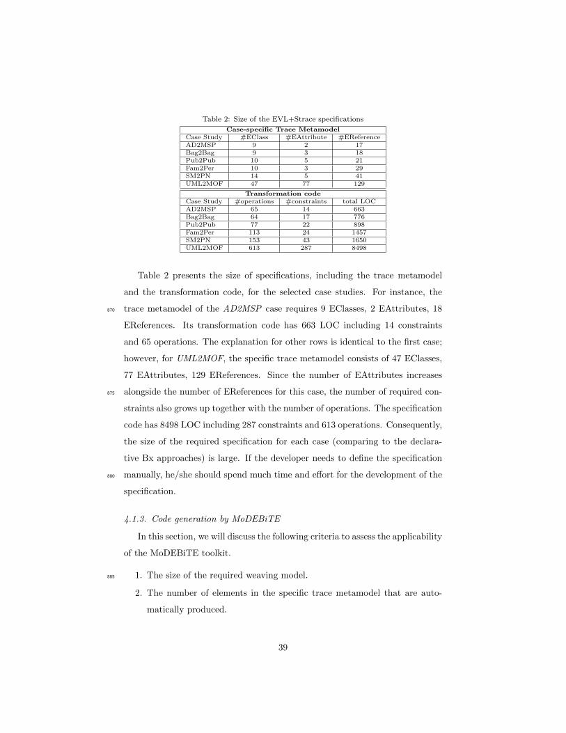
Table 2: Size of the EVL+Strace specifications
Case-specific Trace MetamodelCase Study #EClass #EAttribute #EReferenceAD2MSP 9 2 17Bag2Bag 9 3 18Pub2Pub 10 5 21Fam2Per 10 3 29SM2PN 14 5 41UML2MOF 47 77 129
Transformation codeCase Study #operations #constraints total LOCAD2MSP 65 14 663Bag2Bag 64 17 776Pub2Pub 77 22 898Fam2Per 113 24 1457SM2PN 153 43 1650UML2MOF 613 287 8498
Table 2 presents the size of specifications, including the trace metamodel
and the transformation code, for the selected case studies. For instance, the
trace metamodel of the AD2MSP case requires 9 EClasses, 2 EAttributes, 18870
EReferences. Its transformation code has 663 LOC including 14 constraints
and 65 operations. The explanation for other rows is identical to the first case;
however, for UML2MOF, the specific trace metamodel consists of 47 EClasses,
77 EAttributes, 129 EReferences. Since the number of EAttributes increases
alongside the number of EReferences for this case, the number of required con-875
straints also grows up together with the number of operations. The specification
code has 8498 LOC including 287 constraints and 613 operations. Consequently,
the size of the required specification for each case (comparing to the declara-
tive Bx approaches) is large. If the developer needs to define the specification
manually, he/she should spend much time and effort for the development of the880
specification.
4.1.3. Code generation by MoDEBiTE
In this section, we will discuss the following criteria to assess the applicability
of the MoDEBiTE toolkit.
1. The size of the required weaving model.885
2. The number of elements in the specific trace metamodel that are auto-
matically produced.
39
3. LOC, the number of operations, and the number of constraints that are
automatically generated, must be refined manually, or require to be de-
fined from scratch.890
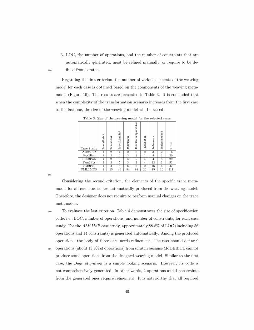
Regarding the first criterion, the number of various elements of the weaving
model for each case is obtained based on the components of the weaving meta-
model (Figure 10). The results are presented in Table 3. It is concluded that
when the complexity of the transformation scenario increases from the first case
to the last one, the size of the weaving model will be raised.
Table 3: Size of the weaving model for the selected cases
Case Study TraceModel
TraceLink
TraceLinkEnd
Attribute
AttributeOperation
Parameter
Reference
SetReference
Tota
l
AD2MSP 1 2 4 2 2 0 3 2 16Bag2Bag 1 2 4 3 3 1 4 2 20Pub2Pub 1 2 5 5 5 4 4 3 29Fam2Per 1 2 5 3 3 4 12 2 32SM2PN 1 4 8 6 6 0 16 6 47
UML2MOF 1 15 40 84 84 26 45 16 311
895
Considering the second criterion, the elements of the specific trace meta-
model for all case studies are automatically produced from the weaving model.
Therefore, the designer does not require to perform manual changes on the trace
metamodels.
To evaluate the last criterion, Table 4 demonstrates the size of specification900
code, i.e., LOC, number of operations, and number of constraints, for each case
study. For the AM2MSP case study, approximately 88.8% of LOC (including 56
operations and 14 constraints) is generated automatically. Among the produced
operations, the body of three ones needs refinement. The user should define 9
operations (about 13.8% of operations) from scratch because MoDEBiTE cannot905
produce some operations from the designed weaving model. Similar to the first
case, the Bags Migration is a simple looking scenario. However, its code is
not comprehensively generated. In other words, 2 operations and 4 constraints
from the generated ones require refinement. It is noteworthy that all required
40
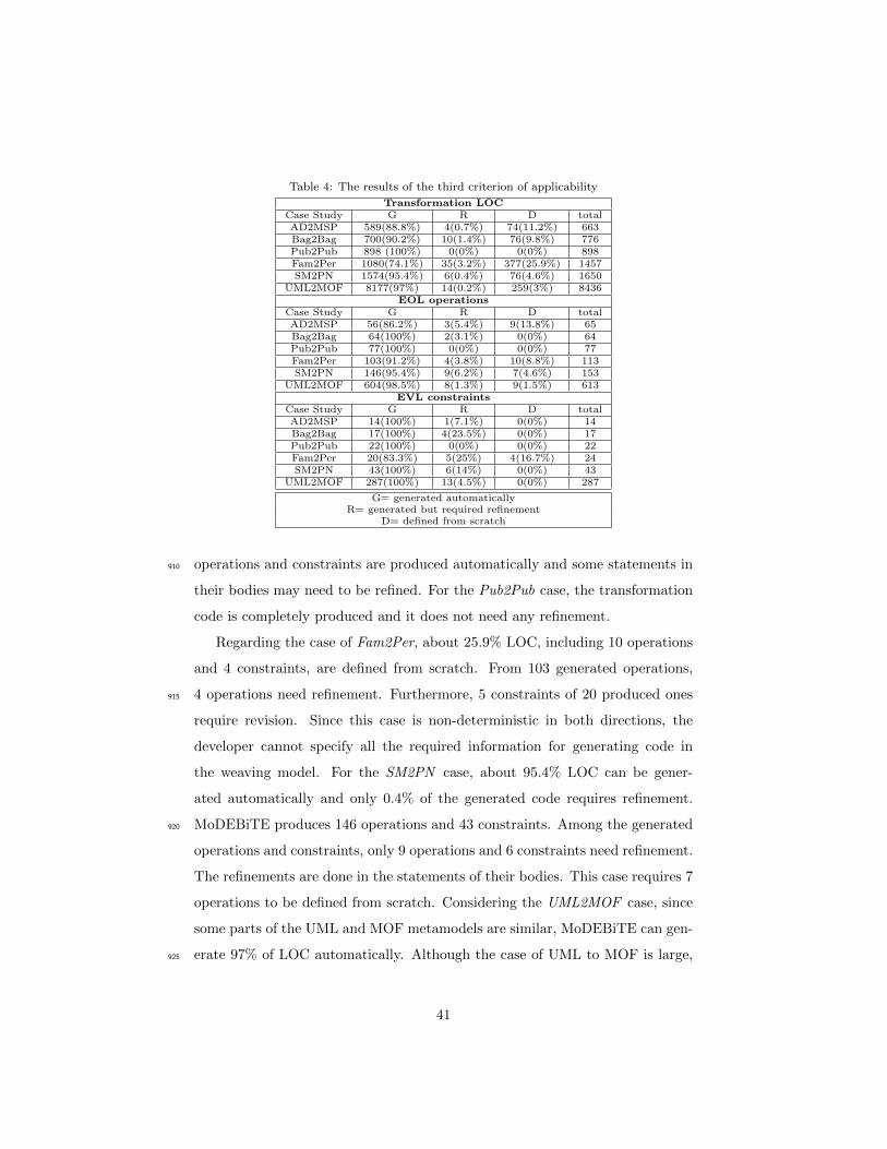
Table 4: The results of the third criterion of applicability
Transformation LOCCase Study G R D totalAD2MSP 589(88.8%) 4(0.7%) 74(11.2%) 663Bag2Bag 700(90.2%) 10(1.4%) 76(9.8%) 776Pub2Pub 898 (100%) 0(0%) 0(0%) 898Fam2Per 1080(74.1%) 35(3.2%) 377(25.9%) 1457SM2PN 1574(95.4%) 6(0.4%) 76(4.6%) 1650
UML2MOF 8177(97%) 14(0.2%) 259(3%) 8436EOL operations
Case Study G R D totalAD2MSP 56(86.2%) 3(5.4%) 9(13.8%) 65Bag2Bag 64(100%) 2(3.1%) 0(0%) 64Pub2Pub 77(100%) 0(0%) 0(0%) 77Fam2Per 103(91.2%) 4(3.8%) 10(8.8%) 113SM2PN 146(95.4%) 9(6.2%) 7(4.6%) 153
UML2MOF 604(98.5%) 8(1.3%) 9(1.5%) 613EVL constraints
Case Study G R D totalAD2MSP 14(100%) 1(7.1%) 0(0%) 14Bag2Bag 17(100%) 4(23.5%) 0(0%) 17Pub2Pub 22(100%) 0(0%) 0(0%) 22Fam2Per 20(83.3%) 5(25%) 4(16.7%) 24SM2PN 43(100%) 6(14%) 0(0%) 43
UML2MOF 287(100%) 13(4.5%) 0(0%) 287
G= generated automaticallyR= generated but required refinement
D= defined from scratch
operations and constraints are produced automatically and some statements in910
their bodies may need to be refined. For the Pub2Pub case, the transformation
code is completely produced and it does not need any refinement.
Regarding the case of Fam2Per, about 25.9% LOC, including 10 operations
and 4 constraints, are defined from scratch. From 103 generated operations,
4 operations need refinement. Furthermore, 5 constraints of 20 produced ones915
require revision. Since this case is non-deterministic in both directions, the
developer cannot specify all the required information for generating code in
the weaving model. For the SM2PN case, about 95.4% LOC can be gener-
ated automatically and only 0.4% of the generated code requires refinement.
MoDEBiTE produces 146 operations and 43 constraints. Among the generated920
operations and constraints, only 9 operations and 6 constraints need refinement.
The refinements are done in the statements of their bodies. This case requires 7
operations to be defined from scratch. Considering the UML2MOF case, since
some parts of the UML and MOF metamodels are similar, MoDEBiTE can gen-
erate 97% of LOC automatically. Although the case of UML to MOF is large,925
41
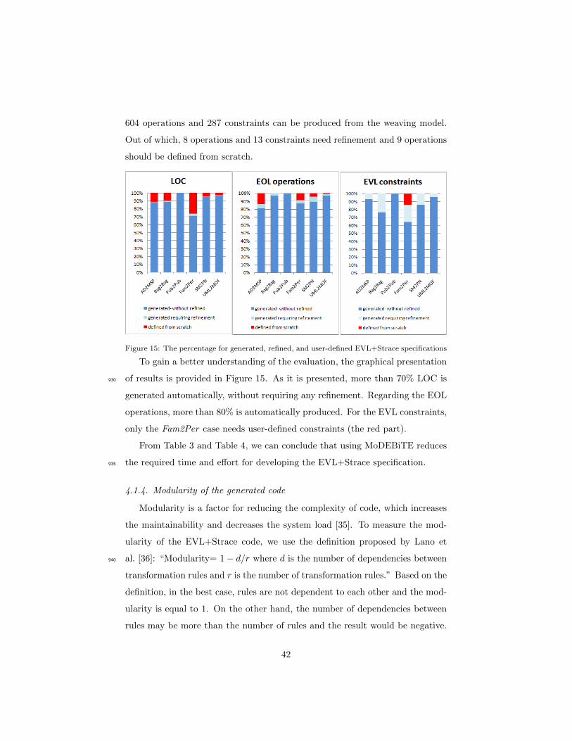
604 operations and 287 constraints can be produced from the weaving model.
Out of which, 8 operations and 13 constraints need refinement and 9 operations
should be defined from scratch.
Figure 15: The percentage for generated, refined, and user-defined EVL+Strace specifications
To gain a better understanding of the evaluation, the graphical presentation
of results is provided in Figure 15. As it is presented, more than 70% LOC is930
generated automatically, without requiring any refinement. Regarding the EOL
operations, more than 80% is automatically produced. For the EVL constraints,
only the Fam2Per case needs user-defined constraints (the red part).
From Table 3 and Table 4, we can conclude that using MoDEBiTE reduces
the required time and effort for developing the EVL+Strace specification.935
4.1.4. Modularity of the generated code
Modularity is a factor for reducing the complexity of code, which increases
the maintainability and decreases the system load [35]. To measure the mod-
ularity of the EVL+Strace code, we use the definition proposed by Lano et
al. [36]: “Modularity= 1 − d/r where d is the number of dependencies between940
transformation rules and r is the number of transformation rules.” Based on the
definition, in the best case, rules are not dependent to each other and the mod-
ularity is equal to 1. On the other hand, the number of dependencies between
rules may be more than the number of rules and the result would be negative.
42
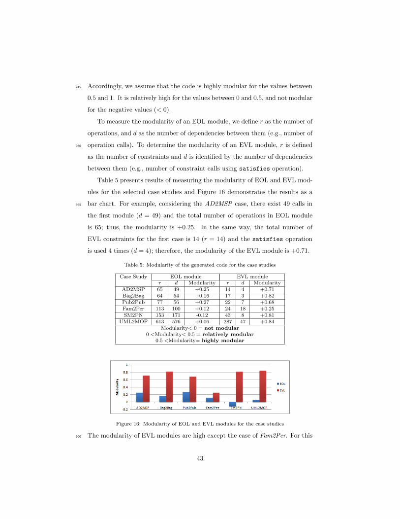
Accordingly, we assume that the code is highly modular for the values between945
0.5 and 1. It is relatively high for the values between 0 and 0.5, and not modular
for the negative values (< 0).
To measure the modularity of an EOL module, we define r as the number of
operations, and d as the number of dependencies between them (e.g., number of
operation calls). To determine the modularity of an EVL module, r is defined950
as the number of constraints and d is identified by the number of dependencies
between them (e.g., number of constraint calls using satisfies operation).
Table 5 presents results of measuring the modularity of EOL and EVL mod-
ules for the selected case studies and Figure 16 demonstrates the results as a
bar chart. For example, considering the AD2MSP case, there exist 49 calls in955
the first module (d = 49) and the total number of operations in EOL module
is 65; thus, the modularity is +0.25. In the same way, the total number of
EVL constraints for the first case is 14 (r = 14) and the satisfies operation
is used 4 times (d = 4); therefore, the modularity of the EVL module is +0.71.
Table 5: Modularity of the generated code for the case studies
Case Study EOL module EVL moduler d Modularity r d Modularity
AD2MSP 65 49 +0.25 14 4 +0.71Bag2Bag 64 54 +0.16 17 3 +0.82Pub2Pub 77 56 +0.27 22 7 +0.68Fam2Per 113 100 +0.12 24 18 +0.25SM2PN 153 171 -0.12 43 8 +0.81
UML2MOF 613 576 +0.06 287 47 +0.84Modularity< 0 = not modular
0 <Modularity< 0.5 = relatively modular0.5 <Modularity= highly modular
Figure 16: Modularity of EOL and EVL modules for the case studies
The modularity of EVL modules are high except the case of Fam2Per. For this960
43

case, the dependency between constraints grows up, therefore, its EVL module
is relatively modular. Among the EOL modules, the modularity of the SM2PN
case is negative because the number of dependecies between EOL operations is
more than the total number of operations. However, the EOL modules of the
other four cases are relatively modular.965
4.1.5. Correctness of the EVL+Strace transformations
In order to measure the extent of correctness, hippocracticness, and stabil-
ity of the EVL+Strace transformations, we define 14 categories of test cases
for each case study. Table 6 presents the categories, their descriptions, and
some examples of test cases from the Pub2Pub case study. By the correctness970
property, we mean that the transformation produces expected models. Stability
means that re-running the transformation after an idle source (target) delta does
not change the target (source) model [27]. However, in hippocraticness, some
non-reflectable information of models is changed and then the transformation
is re-executed [27]. It is expected that the changes do not affect the result of975
transformation and after the execution the changed information is preserved.
Table 7 presents the test results for each case study. The total number of test
cases are demonstrated by tc under the name of each case study. EVL+Strace
leads to two results including expected pass (E) and unexpected pass (U) for
each category of test cases. It is worth noting that for the Families to Persons980
case, the designed test cases in TTC 2017 [27] are particularly analyzed, with-
out considering new tests. In order to evaluate the stability of EVL+Strace
approach, different test cases with consistent models are investigated. Checking
the consistency before enforcement in this approach, enables all transformations
of case studies to pass the test cases.985
For investigating the hippocracticness of EVL+Strace, cases studies with
non-reflectable information are selected. The selected cases are evaluated with
TestHippocracticness testcases. It is worth mentioning that the EVL+Strace
transformations can pass the tests of this category expectedly.
For the AD2MSP case, one of the ElementDeletions tests is unexpectedly990
44
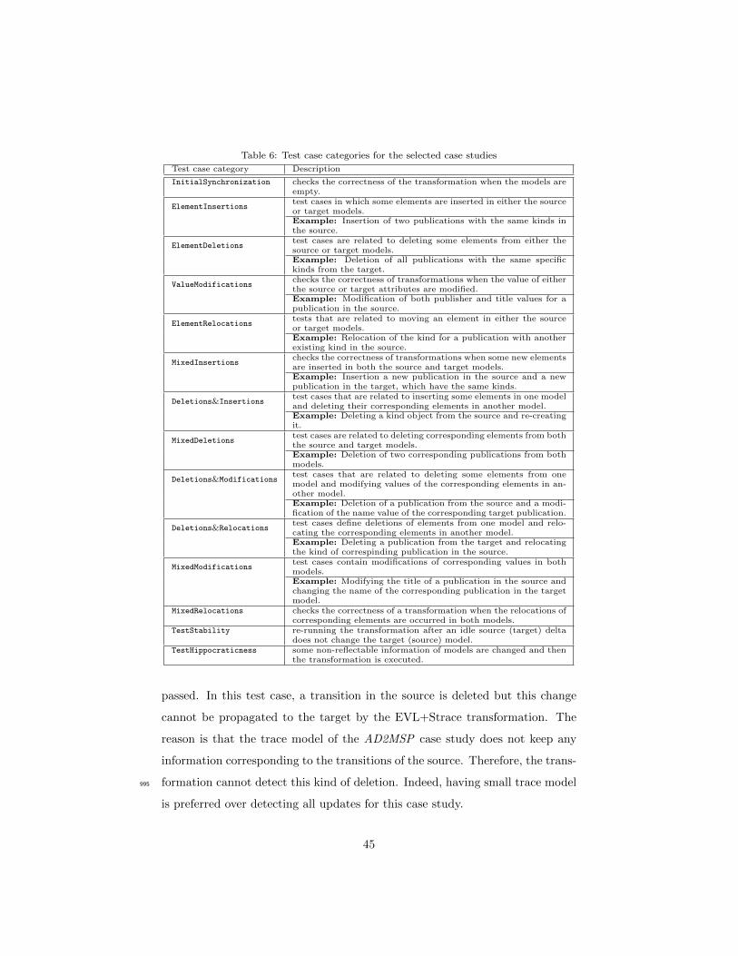
Table 6: Test case categories for the selected case studies
Test case category Description
InitialSynchronization checks the correctness of the transformation when the models areempty.
ElementInsertionstest cases in which some elements are inserted in either the sourceor target models.Example: Insertion of two publications with the same kinds inthe source.
ElementDeletionstest cases are related to deleting some elements from either thesource or target models.Example: Deletion of all publications with the same specifickinds from the target.
ValueModificationschecks the correctness of transformations when the value of eitherthe source or target attributes are modified.Example: Modification of both publisher and title values for apublication in the source.
ElementRelocationstests that are related to moving an element in either the sourceor target models.Example: Relocation of the kind for a publication with anotherexisting kind in the source.
MixedInsertionschecks the correctness of transformations when some new elementsare inserted in both the source and target models.Example: Insertion a new publication in the source and a newpublication in the target, which have the same kinds.
Deletions&Insertionstest cases that are related to inserting some elements in one modeland deleting their corresponding elements in another model.Example: Deleting a kind object from the source and re-creatingit.
MixedDeletionstest cases are related to deleting corresponding elements from boththe source and target models.Example: Deletion of two corresponding publications from bothmodels.
Deletions&Modificationstest cases that are related to deleting some elements from onemodel and modifying values of the corresponding elements in an-other model.Example: Deletion of a publication from the source and a modi-fication of the name value of the corresponding target publication.
Deletions&Relocationstest cases define deletions of elements from one model and relo-cating the corresponding elements in another model.Example: Deleting a publication from the target and relocatingthe kind of correspinding publication in the source.
MixedModificationstest cases contain modifications of corresponding values in bothmodels.Example: Modifying the title of a publication in the source andchanging the name of the corresponding publication in the targetmodel.
MixedRelocations checks the correctness of a transformation when the relocations ofcorresponding elements are occurred in both models.
TestStability re-running the transformation after an idle source (target) deltadoes not change the target (source) model.
TestHippocraticness some non-reflectable information of models are changed and thenthe transformation is executed.
passed. In this test case, a transition in the source is deleted but this change
cannot be propagated to the target by the EVL+Strace transformation. The
reason is that the trace model of the AD2MSP case study does not keep any
information corresponding to the transitions of the source. Therefore, the trans-
formation cannot detect this kind of deletion. Indeed, having small trace model995
is preferred over detecting all updates for this case study.
45
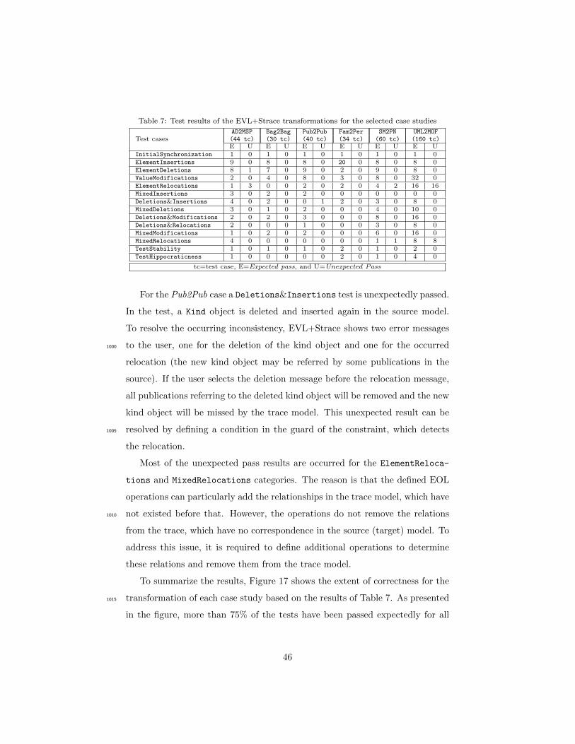
Table 7: Test results of the EVL+Strace transformations for the selected case studies
Test casesAD2MSP Bag2Bag Pub2Pub Fam2Per SM2PN UML2MOF(44 tc) (30 tc) (40 tc) (34 tc) (60 tc) (160 tc)E U E U E U E U E U E U
InitialSynchronization 1 0 1 0 1 0 1 0 1 0 1 0ElementInsertions 9 0 8 0 8 0 20 0 8 0 8 0ElementDeletions 8 1 7 0 9 0 2 0 9 0 8 0ValueModifications 2 0 4 0 8 0 3 0 8 0 32 0ElementRelocations 1 3 0 0 2 0 2 0 4 2 16 16MixedInsertions 3 0 2 0 2 0 0 0 0 0 0 0Deletions&Insertions 4 0 2 0 0 1 2 0 3 0 8 0MixedDeletions 3 0 1 0 2 0 0 0 4 0 10 0Deletions&Modifications 2 0 2 0 3 0 0 0 8 0 16 0Deletions&Relocations 2 0 0 0 1 0 0 0 3 0 8 0MixedModifications 1 0 2 0 2 0 0 0 6 0 16 0MixedRelocations 4 0 0 0 0 0 0 0 1 1 8 8TestStability 1 0 1 0 1 0 2 0 1 0 2 0TestHippocraticness 1 0 0 0 0 0 2 0 1 0 4 0
tc=test case, E=Expected pass, and U=Unexpected Pass
For the Pub2Pub case a Deletions&Insertions test is unexpectedly passed.
In the test, a Kind object is deleted and inserted again in the source model.
To resolve the occurring inconsistency, EVL+Strace shows two error messages
to the user, one for the deletion of the kind object and one for the occurred1000
relocation (the new kind object may be referred by some publications in the
source). If the user selects the deletion message before the relocation message,
all publications referring to the deleted kind object will be removed and the new
kind object will be missed by the trace model. This unexpected result can be
resolved by defining a condition in the guard of the constraint, which detects1005
the relocation.
Most of the unexpected pass results are occurred for the ElementReloca-
tions and MixedRelocations categories. The reason is that the defined EOL
operations can particularly add the relationships in the trace model, which have
not existed before that. However, the operations do not remove the relations1010
from the trace, which have no correspondence in the source (target) model. To
address this issue, it is required to define additional operations to determine
these relations and remove them from the trace model.
To summarize the results, Figure 17 shows the extent of correctness for the
transformation of each case study based on the results of Table 7. As presented1015
in the figure, more than 75% of the tests have been passed expectedly for all
46
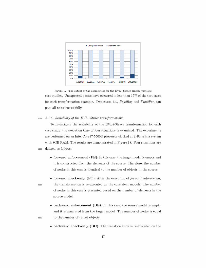
Figure 17: The extent of the correctness for the EVL+Strace transformations
case studies. Unexpected passes have occurred in less than 15% of the test cases
for each transformation example. Two cases, i.e., Bag2Bag and Fam2Per, can
pass all tests successfully.
4.1.6. Scalability of the EVL+Strace transformations1020
To investigate the scalability of the EVL+Strace transformation for each
case study, the execution time of four situations is examined. The experiments
are performed on an Intel Core i7-5500U processor clocked at 2.4Ghz in a system
with 8GB RAM. The results are demonstrated in Figure 18. Four situations are
defined as follows:1025
• forward enforcement (FE): In this case, the target model is empty and
it is constructed from the elements of the source. Therefore, the number
of nodes in this case is identical to the number of objects in the source.
• forward check-only (FC): After the execution of forward enforcement,
the transformation is re-executed on the consistent models. The number1030
of nodes in this case is presented based on the number of elements in the
source model.
• backward enforcement (BE): In this case, the source model is empty
and it is generated from the target model. The number of nodes is equal
to the number of target objects.1035
• backward check-only (BC): The transformation is re-executed on the
47
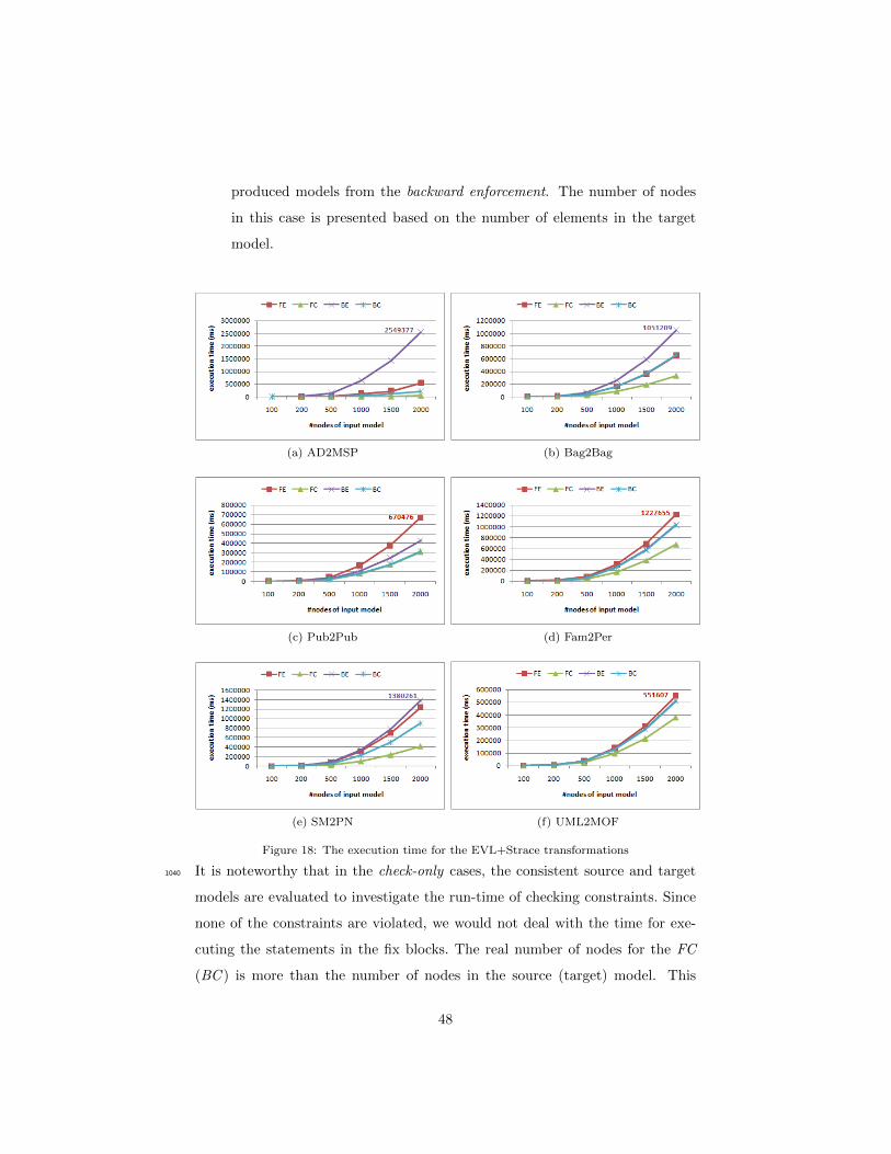
produced models from the backward enforcement. The number of nodes
in this case is presented based on the number of elements in the target
model.
(a) AD2MSP (b) Bag2Bag
(c) Pub2Pub (d) Fam2Per
(e) SM2PN (f) UML2MOF
Figure 18: The execution time for the EVL+Strace transformations
It is noteworthy that in the check-only cases, the consistent source and target1040
models are evaluated to investigate the run-time of checking constraints. Since
none of the constraints are violated, we would not deal with the time for exe-
cuting the statements in the fix blocks. The real number of nodes for the FC
(BC ) is more than the number of nodes in the source (target) model. This
48
number is equal to the total number of nodes in the consistent models of source,1045
trace, and target. In the check-only cases, none of the source and target models
are empty; thus, all constraints should be evaluated on all of the source/target
elements. Additionally, the trace model is not empty and the Deletion, Modi-
fication, and Relocation constraints should be evaluated on the trace elements.
However, in all charts of Figure 18, the run-time of the check-only cases is better1050
than enforcement cases, because it is not required to execute the statements of
fix blocks.
Since the Add-Fix operations (see Figure 14) must create and insert elements
in the source, trace, and target models, they are the most time-consuming state-
ments. In the enforcement cases, the fix blocks (Add-Fix operations) of the Ad-1055
dition constraints are also executed. For the FE case, the Addition constraints,
which are defined in the context of the source meta-elements, are performed.
Regarding the BE case, the specified constraints in the context of the target
meta-elements are executed.
As presented in Figure 18a, Figure 18b, and Figure 18e, the execution time1060
for the BE case is more than the FE because the number of statements in the
backward constraints is more than the forward invariants. However for other
three case studies of Figure 18c, Figure 18d, and Figure 18f, the number of
statements in the forward constraints is more than backward ones. To that end,
the run-time of BE cases are lower than FE . The backward constraints that1065
are defined in the AD2MSP transformation uses recursive operations, which
are time-consuming. Considering the UML2MOF example in Figure 18f, the
execution time of check-only cases is almost close to the running-time of en-
forcement cases. The reason is that the number of Deletion, Modification, and
Relocation constraints is much more than those invariants in other transforma-1070
tion examples (see Table 2). The charts of the last three cases show that the
difference of the execution times for FE and BE is relatively low. It is due to
the equal size of source and target models for these cases.
Comparing the charts in Figure 18, it can be concluded that the running
time of the EVL+Strace transformations is tolerable. Although the size of the1075
49

EVL+Strace specification for the UML2MOF transformation is large and com-
plex in comparison to the first five case studies, the execution time for this case
is not much more than the running time for other cases. It is noteworthy that
the Epsilon languages, including EOL and EVL, are interpreted languages. The
EOL language provides a cached mechanism for the user-defined operations.1080
We use this mechanism to obtain better results.
4.2. Feature-based classification of EVL+Strace
Several taxonomies have been proposed in the context of model transforma-
tions. Among them, feature-based classifications have become very popular. For
instance, robust feature models have been recently proposed for model trans-1085
formation [37], bidirectional transformation [13], model repair [23], and model
synchronization [12]. While all of the mentioned classifications are applica-
ble to our approach, the feature model proposed by Hidaka et al. [13] for Bx
approaches is the most relevant literature. This classification explores the land-
scape of bidirectional model transformation approaches from the perspective of1090
MDE. It has also categorized a number of well-known existing Bx approaches
under the proposed taxonomy, which is precious contribution to Bx community.
To this reason, we investigate EVL+Strace based on the classification features
of Hidaka et al. [13] to identify its position in the design space of bidirectional
transformations.1095
The feature model comprises four main classification axes: 1) Technical
Space, 2) Correspondence, 3) Changes, and 4) Execution. According to the
transformation phases discussed in Section 3.3, the first three axes are related to
the transformation specification and the last one is concerned with the transfor-
mation execution. Figure 19 presents the position of the EVL+Strace approach1100
according to the features of this classification. As indicated in the legend of the
figure, dark boxes show the features that are supported by EVL+Strace, and
white boxes show that the features are not provided. The gray boxes illustrate
the non-leaf features. The relationship between parent and child features are
classified into four groups: 1) Mandatory (child feature is required), 2) Optional1105
50
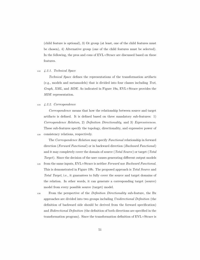
(child feature is optional), 3) Or group (at least, one of the child features must
be chosen), 4) Alternative group (one of the child features must be selected).
In the following, the pros and cons of EVL+Strace are discussed based on these
features.
4.2.1. Technical Space1110
Technical Space defines the representations of the transformation artifacts
(e.g., models and metamodels) that is divided into four classes including Text,
Graph, XML, and MDE. As indicated in Figure 19a, EVL+Strace provides the
MDE representation.
4.2.2. Correspondence1115
Correspondence means that how the relationship between source and target
artifacts is defined. It is defined based on three mandatory sub-features: 1)
Correspondence Relation, 2) Definition Directionality, and 3) Expressiveness.
These sub-features specify the topology, directionality, and expressive power of
consistency relations, respectively.1120
The Correspondence Relation may specify Functional relationship in forward
direction (Forward Functional) or in backward direction (Backward Functional)
and it may completely cover the domain of source (Total Source) or target (Total
Target). Since the decision of the user causes generating different output models
from the same inputs, EVL+Strace is neither Forward nor Backward Functional.1125
This is demonstrated in Figure 19b. The proposed approach is Total Source and
Total Target, i.e., it guarantees to fully cover the source and target domains of
the relation. In other words, it can generate a corresponding target (source)
model from every possible source (target) model.
From the perspective of the Definition Directionality sub-feature, the Bx1130
approaches are divided into two groups including Unidirectional Definition (the
definition of backward side should be derived from the forward specification)
and Bidirectional Definition (the definition of both directions are specified in the
transformation program). Since the transformation definition of EVL+Strace is
51
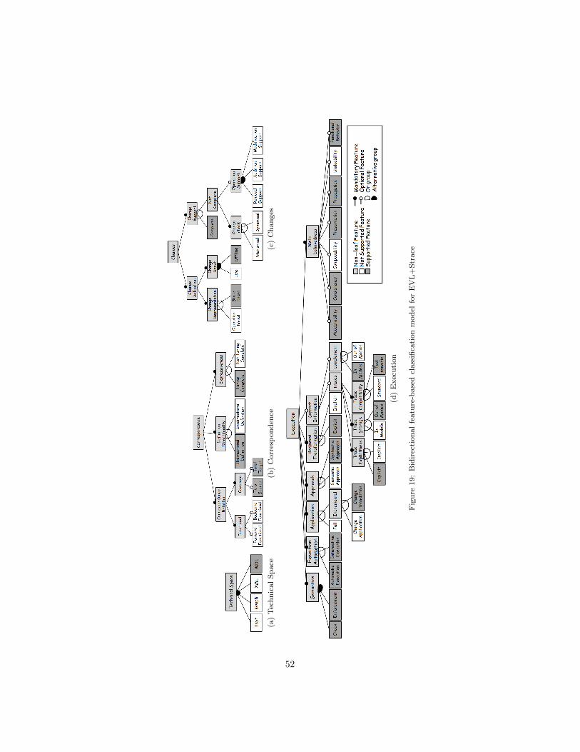
(a)
Tec
hn
ical
Sp
ace
(b)
Corr
esp
on
den
ce(c
)C
han
ges
(d)
Exec
uti
on
Fig
ure
19:
Bid
irec
tion
al
featu
re-b
ase
dcl
ass
ifica
tion
mod
elfo
rE
VL
+S
trace
52
specified for both forward and backward directions, and the transformation en-1135
gine does not need to derive one side from the other side, the proposed approach
is placed in the Bidirectional Definition group. This is indicated in Figure 19b.
For the Expressiveness, due to the fact that EVL is defined on top of EOL,
its program termination is not restricted. Figure 19b presents that EVL+Strace
is Turing Complete, because EOL is a Turing-Complete language [38].1140
4.2.3. Changes
The Changes feature is defined for the approaches, which allow user updates
to be applied on the consistent models, and then provide a way to restore the
consistency. This feature has two compulsory sub-features: Change Definition
and Change Support.1145
The definition of changes is specified based on two characteristics including
Representation and Input. If the user updates are represented by a sequence
of operations, the Change Definition will be Operation-based ; otherwise, it will
be State-based. Change Input defines how the user updates can be recorded.
If they are kept by a specific editor, it will be Live. If they are recorded in1150
the models, it will be Offline. As indicated in Figure 19c, our approach has a
state-based representation and it is an Offline approach. It cannot support Live
changes, which means that updating input models and executing the transfor-
mation process are not synchronized.
Considering the Change Support feature, a Bx approach can be either Com-1155
plete or Not-Complete. Not-Complete approaches cannot support all atomic
updates (Removal, Addition, and Modification). Based on the way of recogniz-
ing the updates, Not-Complete approaches are characterized as Statistical and
Dynamical. The former detects the changes without executing the transfor-
mation, however, the latter needs to run the transformation to recognize the1160
changes. As discussed in Section 3.2, EVL+Strace can completely support the
atomic updates. This is shown in Figure 19c.
53
4.2.4. Execution
The last feature, Execution, is the most complicated one, as presented in Fig-
ure 19d. This feature investigates the Bx approaches based on the bidirectional1165
strategy for establishing the consistency between two models.
The Semantics feature has two cases including Check (to check only the
inter-model consistency) and Enforcement (to enforce the consistency between
models). EVL+Strace supports both the Check and the Enforcement phases,
which means it checks the inter-model consistency before any enforcement. An1170
example of checking before enforcement for the approach is presented in Fig-
ure 7.
The Execution Automation is classified into two categories including Auto-
matic (execution can be run in an automatic mode) and Interactive (execution
ask user to establish the consistency). Although EVL+Strace can be executed1175
automatically, in this paper, we focus on the interactive solution to resolve the
bidirectional inconsistencies (See Example 4). In the interactive case, when a
violation occurs, EVL+Strace shows a feedback to the user. The approach also
proposes to the user some fixing alternatives to restore consistency, automati-
cally. It is worth mentioning that, there is not any interactive and human-in-the-1180
loop implementation among the Bx approaches [13] apart from EVL+Strace.
The Application feature is related to the history of artifacts to restore the
inter-model consistency. If the history of the models is not concerned and the
output model is created from scratch, it will be Full ; otherwise, it will be In-
cremental. The second feature has two sub-features: Change Application and1185
Change Translation. In the former, the Bx approaches obtain the updated ver-
sions of models by propagating the changes. However, in the latter, changes are
explicitly translated from one side to the other. Since EVL+Strace does not cre-
ate the models from scratch and it only adapts them, its Application would be
Incremental. Additionally, EVL+Strace is placed in the group of Change Trans-1190
lation approaches; it means that the approach translates updates explicitly by
defining a sequence of operations. This is presented in Figure 19d.
54
On the Approach feature side, the Bx tools can consider the transformation
as a black box (Semantic) or they use the transformation code for the execution
(Syntactic). Figure 19d illustrates that EVL+Strace is Syntactic. It means that1195
it directly applies transformation code to synchronize the models.
From the perspective of the Backward Transformation feature, if the back-
ward definition is derived from the forward specification (e.g., with the use of
bidirectionalization process), it is considered Implicit. However, if the backward
transformation is not generated by the transformation engine, or the developer1200
explicitly defines it, it is Explicit. Figure 19d demonstrates that EVL+Strace is
Explicit because it is required to define backward transformations explicitly.
The Bx engine requires some kinds of Support Information, which are re-
lated to the ways of storing the structure of the correspondence information.
Two characteristics are investigated: Traces and Complement. The former is1205
studied from three perspectives including Explicitness, Storage, and Compati-
bility. The trace information can be accessed implicitly (Implicit) or it can be
available explicitly (Explicit). Additionally, traces can be kept in the source
or target models (In Models) or they can be stored in a separate model (Out
of Models). The trace metamodel may be Standard or Tool-specific. If one of1210
the models (or both) provides some information that is not contained in the
other model, it is required to transform the missing information by a technique,
which is named Complement. This type of information can be preserved in mod-
els (In Models) or out of them (Out of Models). As indicated in Figure 19d,
EVL+Strace requires accessing the trace elements explicitly (Explicit), which1215
are kept in a separate trace model (Out of Models). It also uses a Tool specific
trace metamodel. The technique of using xmiIds, which has been explained in
Section 3.4.6, can be considered as In Models due to the complement feature.
Finally, the Well-behavedness feature is classified into seven sub-features
including Acceptability, Consistency, Composability, Preservation, Propagation,1220
Undoability, and Functional Behavior. These sub-features are explained in the
following.
The Bx transformation will be an acceptable approach if no modification on
55
the target model results in no change on the source model. In the synchro-
nization case, if no update is applied on models, they must remain unchanged1225
after the execution. EVL+Strace supports Acceptability because it checks the
consistency before any enforcement. The Consistency feature says that the
generated target of the forward transformation from a source model (produced
by a backward transformation from the original target model) is equal to the
original target model. Since both directions of the EVL+Strace transformation1230
are simultaneously executed, the original target model is not changed after the
execution for the second time.
Composability means that two backward transformations with respect to
update operations have the same result with a single backward transformation
with respect to combined update operations. EVL+Strace does not provide the1235
Composability in some non-bijective cases because of its interactive behavior.
The Preservation defines that the effect of user updates on both models should
be preserved after execution. Since the proposed approach acts as a synchronizer
incrementally, it can preserve the information, which is updated by the user;
consequently, our approach supports the Preservation feature.1240
Propagation is the ability of updating both models based on the reflectable
changes while non-reflectable updates are remained in the models after exe-
cution. EVL+Strace supports the Propagation feature because it can provide
synchronization based on the atomic updates and changing models incremen-
tally without modifying the parts that are not concerned in the transformation;1245
hence, the non-propagable parts remained unchanged. The Undoability feature
can be provided if the user reverses the update operations on the target to restore
the original source. According to the EVL+Strace approach, the user should
select the fixing operations in the right order to undo the changes. However,
the proposed approach cannot guarantee Undoability in most cases.1250
Functional Behavior means that the execution result of a transformation is
always unique. For a non-deterministic case study, if additional information is
provided for the Bx approach, the ultimate outcome should be guaranteed to be
determined. According to the EVL+Strace approach, the mentioned additional
56
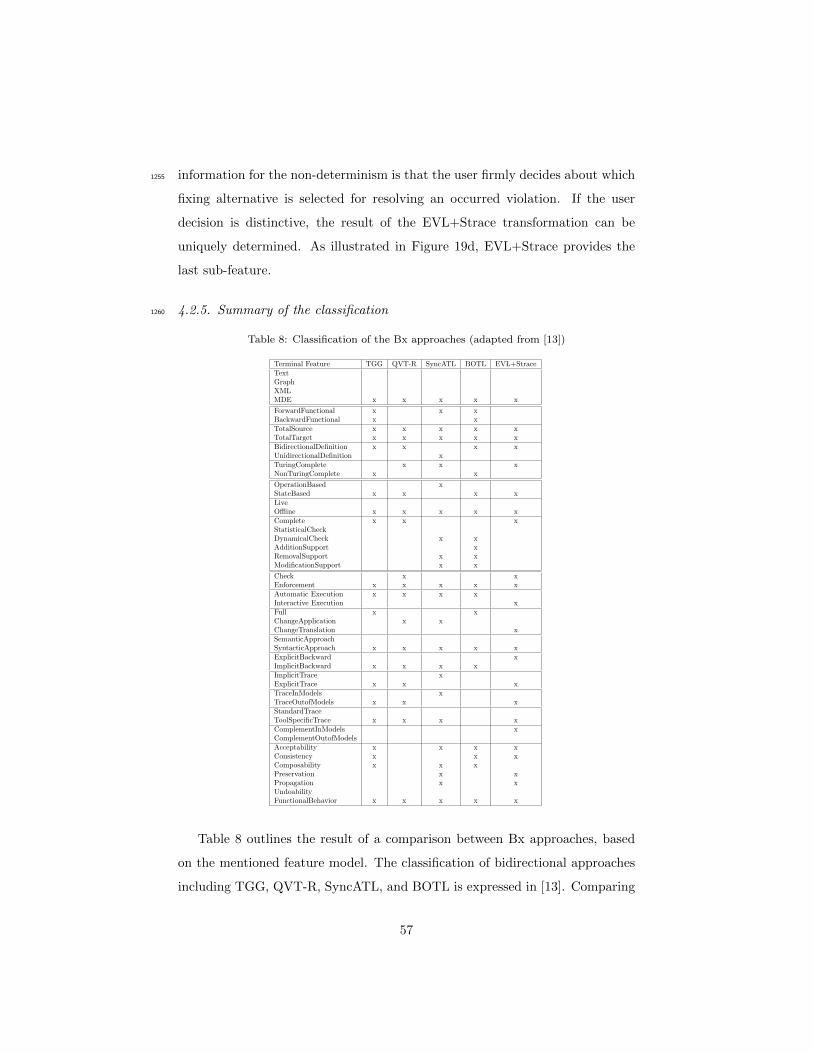
information for the non-determinism is that the user firmly decides about which1255
fixing alternative is selected for resolving an occurred violation. If the user
decision is distinctive, the result of the EVL+Strace transformation can be
uniquely determined. As illustrated in Figure 19d, EVL+Strace provides the
last sub-feature.
4.2.5. Summary of the classification1260
Table 8: Classification of the Bx approaches (adapted from [13])
Terminal Feature TGG QVT-R SyncATL BOTL EVL+StraceTextGraphXMLMDE x x x x x
ForwardFunctional x x xBackwardFunctional x xTotalSource x x x x xTotalTarget x x x x xBidirectionalDefinition x x x xUnidirectionalDefinition xTuringComplete x x xNonTuringComplete x x
OperationBased xStateBased x x x xLiveOffline x x x x xComplete x x xStatisticalCheckDynamicalCheck x xAdditionSupport xRemovalSupport x xModificationSupport x x
Check x xEnforcement x x x x xAutomatic Execution x x x xInteractive Execution xFull x xChangeApplication x xChangeTranslation xSemanticApproachSyntacticApproach x x x x xExplicitBackward xImplicitBackward x x x xImplicitTrace xExplicitTrace x x xTraceInModels xTraceOutofModels x x xStandardTraceToolSpecificTrace x x x xComplementInModels xComplementOutofModelsAcceptability x x x xConsistency x x xComposability x x xPreservation x xPropagation x xUndoabilityFunctionalBehavior x x x x x
Table 8 outlines the result of a comparison between Bx approaches, based
on the mentioned feature model. The classification of bidirectional approaches
including TGG, QVT-R, SyncATL, and BOTL is expressed in [13]. Comparing
57
EVL+Strace to these approaches, it is concluded that EVL+Strace is the first
interactive Bx approach, which can provide various fixing options for consis-1265
tency restoration. Among the well-behavedness properties, propagation, and
preservation are not supported by many Bx approaches [13]; however, compre-
hensive support for these features are provided in our approach. In addition,
the proposed Bx transformation can be used as a synchronizer, which executes
the forward and backward transformations, simultaneously.1270
5. Discussion and future work
In this section, we investigate our work from several aspects. Firstly, bidi-
rectionality features of the EVL+Strace approach, which are novel compared to
other well-known approaches, are addressed. Secondly, the advantage of using
domain-specific trace metamodel versus general metamodel is studied. Thirdly,1275
the pros and cons of the MoDEBiTE application are investigated. Also we
elaborate on how to extend this tool for other bidirectional languages. Lastly,
the limitations of the EVL+Strace approach are discussed from the verification
perspective.
5.1. Bidirectional properties1280
EVL+Strace proposes an interactive transformation system that is able to
detect inconsistencies between the source and target models, as well as providing
information about the violated constraints. In special cases, where no conflict
exists between the manual changes on the source and target models, it is possible
to specify the constraint in order to be fixed automatically. Benefiting from the1285
EVL syntax, we can rewrite the constraints to make the auto-fix possible. To
achieve this goal, the structure of the code is changed, in which the statements
of the fix blocks are moved to the check block.
When several errors occur in the interactive case of EVL+Strace, the user
must put in extra effort to select from the alternatives. However, being inter-1290
active can be beneficial in check-only mode. In this case, the user may desire
58
to evaluate the conformance of two models with regard to the transformation
definition, but it is not needed to enforce the consistency. Unlike the QVT-R
approach, EVL+Strace does not need to specify the mode of execution. If the
user does not enforce any fix alternative to restore the consistency of one of the1295
detected violations, that violation remains in the check-only mode. The selection
order of fixing the violated constraints is important in some cases. Therefore,
EVL+Strace organizes the order of execution by defining some lazy invariants,
which is required to be called from other constraints. One of the limitations of
EVL+Strace is that it prefers deletion over modification. That is to say, when it1300
finds a conflict between a modification on one model and a deletion on another,
it deletes the modified elements to restore the consistency.
The proposed approach defines non-functional correspondence relation be-
tween source and target models. Therefore, the topology of the transformation
specification is non-functional. From the perspective of the transformation exe-1305
cution, in the interactive case of EVL+Strace, when a single fixing alternative is
proposed for each constraint, its behavior will be functional. On the other hand,
in the automatic case, the result of execution is unique if the transformation is
informed of the user decision (by providing additional information).
If EVL+Strace only uses Addition constraints for one side (e.g., Addition1310
constraints which are defined in the context of source meta-classes) and the other
model (e.g., target model) is empty, the approach will act as a transformer, not
a synchronizer. From the synchronization perspective, the proposed approach
is a synchronizer with reconciliation [12]. The synchronizer with reconciliation
applies some decision strategies to handle the conflicting updates on source and1315
target models. The forward and backward directions of the EVL+Strace trans-
formation are executed simultaneously. When both source and target models are
evolved manually, the approach will reconcile the user changes and propagate
them to the models in a single execution.
59
5.2. Specific versus generic trace metamodel1320
The main contribution of EVL+Strace is that it exploits trace information to
preserve the correspondence relations. If the traceability information is defined
as a model, MDE processes such as validation, transformation, and visualization
can be performed on this model by using model-driven standard tools. The trace
model should conform to a metamodel. To specify the trace metamodel, two1325
alternatives can be proposed as follows.
• Using a generic trace metamodel: In this case, a trace link can con-
nect an arbitrary number of source elements to a number of target elements
of any type. It is possible to propose a comprehensive metamodel, which
classifies the trace links. This classification may be characterized based1330
on some correspondence features, such as the cardinality of the source/-
target elements, the structure of elements (e.g., class to class, class to
attribute, class to reference), and dependencies between trace links. How-
ever, creating such a metamodel is not feasible because the number of
correspondence features is high. On the other hand, the type of trace1335
links must be encoded with the aid of general datatypes (e.g., string). In
consequence, illegitimate trace links are not prevented. In generic trace
models, the values of source/target attributes cannot be preserved by their
real types. Then, some type-converting functions are required to pass the
values between source, trace, and target models.1340
• Using a domain-specific trace metamodel: By means of a specific
metamodel, it is possible to define various strongly typed trace links. To
define the types of trace links, the trace metamodel must provide inter-
metamodel references [14]. To accomplish that, a modeling tool, such as
EMF, should be employed. The manipulation operations for the trace1345
models must be specific to the source and target domains. Defining such
operations requires much more effort in comparison to using a generic
metamodel. Accordingly, if it is possible to automatically generate the
specific trace metamodel and produce some parts of the operations, this
60
alternative would be much more trustworthy and valuable.1350
EVL+Strace uses the second alternative for traceability. As discussed, the
second approach requires a modeling toolkit to automatically generate the trace
metamodel and the code of corresponding operations. Consequently, MoDEB-
iTE is employed to specify a weaving model between the source and target
metamodels. The proposed toolkit takes that model to produce the specific1355
trace metamodel as well as EOL operations for manipulating three models.
5.3. Extending MoDEBiTE
MoDEBiTE is a tool to generate the bidirectional transformation code in
EVL+Strace with the aid of the MDE principles. The source and target meta-
models, which should be upload in MoDEBiTE, must be from the ECore type.1360
Therefore, the toolkit should be extended to accept other types of metamodels.
In some cases, the generated code needs to be refined. To alleviate this issue,
we should investigate more alternative representations based on various trans-
formation scenarios to provide examples for designing the weaving model. By
studying different case studies, reoccurring patterns in transformation scenarios1365
can be identified. The patterns can be used to enhance the structure of the
weaving metamodel. Consequently, the model to text transformations can be
improved to generate more parts of code.
As mentioned before, the transformation code in EVL is executed interac-
tively; however, it is possible to transfer the statements of the EVL constraints1370
from the fix blocks to the check block. In this case, the code will be performed
automatically. MoDEBiTE generates the transformation code, which is exe-
cuted in the interactive manner. Although changing the code (transferring the
fix blocks) is an easy task, it is possible to add the capability of generating the
code with automatic behavior to MoDEBiTE. The step of validating the weav-1375
ing model can be enhanced to lead the developer for designing correct models.
We should define more accurate invariants for this step to avoid errors, that are
happened because of bad design.
61
MoDEBiTE can be extended to support the engineering of bidirectional
transformations, that are written in other well-known languages, such as QVT-1380
R. To put this idea into practice, it is required to define a more general struc-
ture for the weaving metamodel. Two model to model transformations should
be specified, one from the general metamodel to the proposed weaving meta-
model of this paper, and another from the general metamodel to the QVT-R
metamodel. To produce the QVT-R transformation code, a model to text trans-1385
formation from the QVT-R metamodel to its code should be defined. It is ideal
if a bidirectional transformation between the weaving metamodel of this paper
and the QVT-R metamodel will be defined. In this case, it is possible to trans-
form the specification of the QVT-R program to the EVL+Strace code that
provides interoperability between bidirectional approaches.1390
5.4. Bx compatibility in EVL+Strace
An EVL+Strace code consists of some EVL constraints. Each constraint is
participated in a single direction (forward or backward). If these constraints
can be completely produced from the weaving model, the transformation con-
struction guarantees the compatibility of the forward and backward directions.1395
MoDEBiTE, however, cannot generate some parts of the addition constraints,
as it is explained in Section 3.4.6. The Bx compatibility cannot be guaranteed in
the EVL+Strace approach since developers are allowed to change the generated
code. For the future work, two options are considered. First, the MoDEBiTE
weaving metamodel can be enhanced such that the EVL+Strace code is fully1400
generated. Second, some proof techniques, such as graph transformations [39],
can be used to verify the compatibility of the forward and backward transfor-
mations.
6. Related Work
In this section, the related work on both bidirectional model transformation1405
approaches and model-driven development of transformation code is briefly ex-
plained.
62
6.1. Bidirectional Model Transformation Approaches
There are several works on bidirectional approaches, which in this research
are divided into two groups, from the language directionality perspective. First,1410
a bidirectional MTL can be used to specify Bx. Second, a unidirectional MTL
can be applied to define forward and backward directions of transformation,
separately. In the following, each case is explained.
6.1.1. Using bidirectional MTL
A bidirectional MTL expresses the forward and backward directions of the1415
transformation simultaneously. The primary advantage of this approach is that
the transformation construction guarantees the compatibility of both forward
and backward directions [10]. However, in some cases, there is no solution for
defining a single specification in both directions via the bidirectional MTL [21].
QVT-R [16], TGG [17], and BOTL [18] are the examples of bidirectional MTLs.1420
QVT-R is a user-friendly relational language, which supports complex object
pattern matching and object template creation [16]. In recent years, a num-
ber of engines has been proposed to support QVT-R. Some engines, such as
Janus [11] and Echo [40], are the solver-based engines. However, the former was
not emitted as a plug-in to become usable, and the latter is not configurable with1425
the new versions of Eclipse. The compiler-based engines, such as QVTmedini11
and ModelMorf, do not have a complete support for the QVT-R standardiza-
tion [41]. The Eclipse QVTd12 is an on-going Model-to-Model Transformation
(MMT) project [42], which is being implemented under active development. In
short, QVT-R does not have a comprehensive tool support due to its inherent1430
language ambiguities.
TGG is a formally founded language to define the correspondence between
two types of models in a declarative and bidirectional way [43]. In addition to
model transformation, TGG can also be used for model integration and model
11projects.ikv.de/qvt/12https://projects.eclipse.org/projects/modeling.mmt.qvtd
63
synchronization. Several tools have been developed to implement TGG [44].1435
However, they do not provide adaptive notations; therefore, working with the
TGG tools requires considerable learning efforts. BOTL is a relational batch-
oriented language, which can only provide bijective transformation [18]. A bijec-
tive transformation is a special case of Bx defining a one-to-one correspondence
between source and target models.1440
6.1.2. Using unidirectional MTL
The second group of approaches uses a unidirectional MTL for defining
bidirectionality, which has two alternatives. The first one is the bidirection-
alization process, in which a unidirectional language is applied for specifica-
tion of the forward direction. The transformation engine then calculates the1445
backward direction and guarantees the preservation of bidirectional proper-
ties [19, 45, 46, 40]. SyncATL [19] is an extension of the AtlanMod Trans-
formation Language (ATL) [20] virtual machine that uses bidirectionalization
process to provide model synchronization. However, the cost of this approach
is not efficient for some Bx case studies [19].1450
The second alternative is to encode both forward and backward transforma-
tions by a unidirectional MTL, independently. In this case, the bidirectional
properties, including the compatibility of both directions, should be guaranteed
by formal verification [47]. Despite the expensive and complex task of verifi-
cation, this case is more effective on the Bx case studies in comparison to the1455
bidirectionalization approach. Poskitt et al. [39] have proposed to use EVL for
Bx for the first time. Their approach checks the compatibility of two models by
means of the EVL check blocks. Additionally, when the inconsistency between
models occurs, it resolves the violation with the EWL transformation. However,
several practical drawbacks arise when dealing with this approach:1460
1. It has not taken into account how would be possible to trigger from an
EVL constraint to the EWL wizard.
2. It is not possible to recognize old updated model elements from new in-
serted ones.
64

3. It is not clear how to propagate value modifications from one model to1465
the other one.
4. It is undesirable to apply two languages in order to specify a bidirectional
transformation.
To resolve all these issues, the EVL+Strace bidirectional approach is proposed.
Our approach uses the EOL operations in the fix blocks of an EVL constraint,1470
instead of using EWL wizard. Since EVL is based on the EOL constraints, de-
velopers do not need to learn alternative language, such as EWL. Furthermore,
the information of source and target models is preserved in a trace model, which
makes it possible to propagate changes in both directions.
6.2. Model-Driven Development of Transformation Code1475
Developers usually specify source-target relationships by writing a trans-
formation program in an appropriate MTL. In this case, the transformation
specification is equal to the transformation implementation. However, some
approaches raise the abstraction level of the specification by defining the re-
lationships in a weaving model. A weaving model is a correspondence model1480
conformed to a particular metamodel. The model includes abstract and declar-
ative links between elements of the source and target metamodels [48]. The
idea of using weaving models was first introduced by Didonet Del Fabro [49].
He developed a generic and adaptable framework for management of weaving
models and metamodels called AtlanMod Model Weaver13 (AMW). MeTAGeM1485
is an extension of AMW that defines four levels for generating a transformation
program [50]. It supports to generate unidirectional transformations written in
the hybrid MTLs, such as ATL [20] and the Epsilon Transformation Language
(ETL) [7]. Another framework extending MeTAGeM, named MeTAGeM-Trace,
has been developed based on AMW. It can produce code for creating a trace1490
model in addition to the hybrid transformation code [51, 52]. Like MeTAGeM,
it only develops the code of unidirectional transformations.
13http://www.eclipse.org/gmt/amw/
65
TransML [53, 54] considers a transformation code as a software artifact,
which has to pass all phases of a software engineering life cycle including require-
ment, analysis, design, implementation, and testing. It proposes requirement,1495
mapping, and behavioral languages. In the requirement language, the specifica-
tion of the relationships between two metamodels is called inter-modeling [55].
TransML proposes to generate QVT-R transformation code; however, as already
mentioned, the QVT-R language does not have an appropriate implementation
tool. TROPIC is a framework that specifies different abstraction levels, includ-1500
ing mapping view and concrete view, for developing a transformation [56]. It
facilitates productivity of transformation development; however, it only provides
unidirectional transformations.
It is noteworthy that AMW [49] and its extensions [50, 51, 52] thoroughly
support the generation of transformation code from abstract model, while the1505
implementations of transML [53, 54] and TROPIC [56] provide only partial
support. However, AMW is not compatible with the new versions of Eclipse
development, and its extension cannot be integrated with the state-of-art Eclipse
modeling plug-ins. By contrast, MoDEBiTE is developed on top of the Epsilon
platform, which is significantly portable and mature [57].1510
7. Conclusion
In this research, the authors proposed the bidirectional transformation ap-
proach of EVL+Strace. The approach uses EVL with a domain-specific trace
model. This trace model includes strongly-typed trace links that prevents the
developer from defining invalid links. The EVL+Strace approach uses those1515
links to recognize independent manual changes on the source and target mod-
els. After recognizing the changes, e.g., addition, modification, or deletion, some
fixing alternatives are automatically proposed to resolve the inconsistencies.
In order to present the extent of correctness and scalability of EVL+Strace
and the applicability of MoDEBiTE, we have performed a comprehensive eval-1520
uation on six Bx case studies. The results show that the Bx approach is stable
66
and produces correct models in most cases. The superiority of EVL+Strace is
also illustrated in comparison to some well-known bidirectional languages, such
as TGG, QVT-R, and BOTL, by using a feature-based Bx classification model.
Since EVL+Strace is able to act as a synchronizer, it is also compared to the1525
SyncATL approach. It should be noted that, the proposed Bx approach is the
first interactive, human-in-the-loop, and practical approach, which can provide
propagation and preservation.
The EVL+Strace specification consists of the specific trace metamodel and
the EVL+Strace code. To develop the specification of the EVL+Strace trans-1530
formation, this paper proposed to use the MDE principles. In order to put
this idea into practice, the EMF-based MoDEBiTE toolkit is developed that
provides the following outputs:
1. A metamodel for designing a weaving model
2. A model validator for the designed model1535
3. An M2M HOT taking the model to generate a specific trace metamodel
4. A number of M2T HOTs for producing the Bx code and its requirements
such as EOL operations
Using MoDEBiTE is beneficial because the developer does not require writing
all parts of EVL+Strace code. The time and effort of the transformation devel-1540
opment will decrease, and the generated code will become modular. In addition,
the developer do not need to spend time for designing the specific trace meta-
model with EMF-based tools in an apart environment. Although the produced
EVL+Strace constraint code must be manually revised, several artifacts are
comprehensively generated, i.e., the required EOL operations for checking and1545
fixing models, the EOL documents for making operations easy to use, and a
semantically rich trace metamodel.
In conclusion, the goal of the paper is summarized in three points. Firstly, a
novel Bx approach (called EVL+Strace) is proposed for specifying bidirectional
transformations via EVL with the aid of the case-specific trace metamodel. Sec-1550
ondly, the EVL+Strace approach is classified based on the Bx feature model and
67
is compared to some well-known bidirectional languages and methods. Finally,
the MoDEBiTE toolkit is developed by means of the Epsilon family of languages
and tools, which applies the MDE principles on generating the EVL+Strace ar-
tifacts, i.e., the trace metamodel, EOL operations, EOL documentations, and1555
EVL constraints.
The potential possibilities for future work are as follows. Firstly, more com-
plicated case studies should be investigated. The larger bidirectional examples
give us the opportunity to enrich the weaving metamodel for generating more
lines of code, automatically. Exploring diverse cases results in producing more1560
various EOL operations. Secondly, the MoDEBiTE toolkit should be extended
to support rich validation of weaving model. The toolkit should generate a run
configuration automatically for EVL+Strace, that makes testing easier.
Acknowledgements
The authors would like to thank the Epsilon team, especially Dimitris Kolovos.1565
References
[1] D. C. Schmidt, Model-driven engineering, IEEE Computer 39 (2) (2006)
25–31. doi:10.1109/MC.2006.58.
[2] S. Sendall, W. Kozaczynski, Model Transformation: The Heart and Soul of
Model-Driven Software Development, Software, IEEE 20 (5) (2003) 42–45.1570
doi:10.1109/MS.2003.1231150.
[3] M. Brambilla, J. Cabot, M. Wimmer, Model-Driven Software Engineering
in Practice, Synthesis Lectures on Software Engineering, Morgan & Clay-
pool Publishers, 2012. doi:10.2200/S00441ED1V01Y201208SWE001.
[4] M. Tisi, F. Jouault, P. Fraternali, S. Ceri, J. Bezivin, On the use of higher-1575
order model transformations, in: Model Driven Architecture - Foundations
and Applications: 5th European Conference, ECMDA-FA 2009, 2009, pp.
18–33. doi:10.1007/978-3-642-02674-4_3.
68
[5] D. S. Kolovos, R. F. Paige, F. A. Polac, The Epsilon Object Language
(EOL), in: Model Driven Architecture – Foundations and Applications:1580
Second European Conference, ECMDA-FA 2006., 2006, pp. 128–142. doi:
10.1007/11787044_11.
[6] D. Kolovos, R. Paige, F. Polack, On the Evolution of OCL for Capturing
Structural Constraints in Modelling Languages, in: Rigorous Methods for
Software Construction and Analysis, Vol. 5115 of Lecture Notes in Com-1585
puter Science, 2009, pp. 204–218. doi:10.1007/978-3-642-11447-2_13.
[7] D. Kolovos, R. Paige, F. Polack, The Epsilon Transformation Lan-
guage, in: Theory and Practice of Model Transformations, Vol. 5063
of Lecture Notes in Computer Science, 2008, pp. 46–60. doi:10.1007/
978-3-540-69927-9_4.1590
[8] D. S. Kolovos, R. F. Paige, F. A. Polac, L. M. Rose, Update Transforma-
tions in the Small with the Epsilon Wizard Language, Journal of Object
Technology 6 (9) (2007) 53–69. doi:10.5381/jot.2007.6.9.a3.
[9] L. M. Rose, R. F. Paige, D. S. Kolovos, F. A. C. Polack, The Epsilon
Generation Language, in: Model Driven Architecture – Foundations and1595
Applications: 4th European Conference, ECMDA-FA 2008, 2008, pp. 1–16.
doi:10.1007/978-3-540-69100-6_1.
[10] K. Czarnecki, J. Foster, Z. Hu, R. Lammel, A. Schurr, J. Terwilliger, Bidi-
rectional Transformations: A Cross-Discipline Perspective, in: Theory and
Practice of Model Transformations, Vol. 5563 of Lecture Notes in Computer1600
Science, 2009, pp. 260–283. doi:10.1007/978-3-642-02408-5_19.
[11] A. Cicchetti, D. Di Ruscio, R. Eramo, A. Pierantonio, Jtl: A bidirectional
and change propagating transformation language, in: Software Language
Engineering: Third International Conference, SLE 2010, 2011, pp. 183–202.
doi:10.1007/978-3-642-19440-5_11.1605
69
[12] M. Antkiewicz, K. Czarnecki, Design space of heterogeneous synchroniza-
tion, in: Generative and Transformational Techniques in Software Engi-
neering II: International Summer School, GTTSE 2007, 2008, pp. 3–46.
doi:10.1007/978-3-540-88643-3_1.
[13] S. Hidaka, M. Tisi, J. Cabot, Z. Hu, Feature-based classification of bidi-1610
rectional transformation approaches, Software & Systems Modeling 15 (3)
(2016) 907–928. doi:10.1007/s10270-014-0450-0.
[14] N. Drivalos, D. S. Kolovos, R. F. Paige, K. J. Fernandes, Engineering
a dsl for software traceability, in: Software Language Engineering: First
International Conference, SLE 2008, 2009, pp. 151–167. doi:10.1007/1615
978-3-642-00434-6_10.
[15] D. S. Kolovos, R. F. Paige, F. A. Polac, On-demand merging of traceability
links with models, in: 2nd EC-MDA Workshop on Traceability (July 2006),
2006.
[16] Meta object facility query/view/transformation, v1.3 (June 2016).1620
URL http://www.omg.org/spec/QVT/1.3/PDF
[17] A. Anjorin, E. Leblebici, A. Schurr, 20 years of triple graph grammars: A
roadmap for future research, ECEASST 73. doi:10.14279/tuj.eceasst.
73.1031.
[18] P. Braun, F. Marschall, Transforming Object Oriented Models with BOTL,1625
Electronic Notes in Theoretical Computer Science 72 (3) (2003) 103 – 117.
doi:10.1016/S1571-0661(04)80615-7.
[19] Y. Xiong, D. Liu, Z. Hu, H. Zhao, M. Takeichi, H. Mei, Towards au-
tomatic model synchronization from model transformations, in: ASE
’07: Proceedings of the twenty-second IEEE/ACM international confer-1630
ence on Automated software engineering, ACM, 2007, pp. 164–173. doi:
10.1145/1321631.1321657.
70
[20] F. Jouault, F. Allilaire, J. Bezivin, I. Kurtev, ATL: A model transformation
tool , Science of Computer Programming 72 (12) (2008) 31 – 39. doi:
10.1016/j.scico.2007.08.002.1635
[21] B. Westfechtel, Case-based exploration of bidirectional transformations in
QVT Relations, Software & Systems Modeling (2016) 1–41doi:10.1007/
s10270-016-0527-z.
[22] E. Guerra, J. de Lara, An Algebraic Semantics for QVT-Relations Check-
only Transformations, Fundamenta Informaticae 114 (1) (2012) 73–101.1640
doi:10.3233/FI-2011-618.
[23] N. Macedo, T. Jorge, A. Cunha, A feature-based classification of model re-
pair approaches, IEEE Transactions on Software Engineering 43 (7) (2017)
615–640. doi:10.1109/TSE.2016.2620145.
[24] P. Stevens, Bidirectional model transformations in qvt: semantic issues1645
and open questions, Software & Systems Modeling 9 (1) (2008) 7. doi:
10.1007/s10270-008-0109-9.
URL http://dx.doi.org/10.1007/s10270-008-0109-9
[25] D. Steinberg, F. Budinsky, M. Paternostro, E. Merks, EMF: Eclipse Mod-
eling Framework 2.0, 2nd Edition, Addison-Wesley Professional, 2009.1650
[26] L. Samimi-Dehkordi, B. Zamani, S. Kolahdouz-Rahimi, From trace-based
inter-model validation to bidirectional model synchronization with recon-
ciliation, in: Computer and Knowledge Engineering (ICCKE), 2015 5th In-
ternational Conference on, 2015, pp. 123–130. doi:10.1109/ICCKE.2015.
7365871.1655
[27] A. Anjorin, T. Buchmann, B. Westfechtel, The Families to Persons Case,
in: Transformation Tool Contest 2017, CEUR-WS, 2017, pp. 15–30.
[28] L. Samimi-Dehkordi, B. Zamani, S. K. Rahimi, Solving the families to
persons case using evl+strace, in: Proceedings of the 10th Transformation
Tool Contest (TTC 2017), 2017, pp. 54–62.1660
71

[29] M. Wimmer, G. Kappel, A. Kusel, W. Retschitzegger, J. Schoenboeck,
W. Schwinger, Towards an expressivity benchmark for mappings based on
a systematic classification of heterogeneities, in: Proceedings of the First
International Workshop on Model-Driven Interoperability, MDI ’10, ACM,
New York, NY, USA, 2010, pp. 32–41. doi:10.1145/1866272.1866278.1665
URL http://doi.acm.org/10.1145/1866272.1866278
[30] G. Kappel, H. Kargl, T. Reiter, W. Retschitzegger, W. Schwinger,
M. Strommer, M. Wimmer, A framework for building mapping op-
erators resolving structural heterogeneities, in: Information Systems
and e-Business Technologies: 2nd International United Information Sys-1670
tems Conference UNISCON 2008, 2008, pp. 158–174. doi:10.1007/
978-3-540-78942-0_18.
[31] R. F. Paige, N. Drivalos, D. S. Kolovos, K. J. Fernandes, C. Power, G. K.
Olsen, S. Zschaler, Rigorous identification and encoding of trace-links in
model-driven engineering, Software & Systems Modeling 10 (4) (2011) 469–1675
487. doi:10.1007/s10270-010-0158-8.
[32] S. Zschaler, D. S. Kolovos, N. Drivalos, R. F. Paige, A. Rashid, Domain-
specific metamodelling languages for software language engineering, in:
Software Language Engineering: Second International Conference, SLE
2009, 2010, pp. 334–353. doi:10.1007/978-3-642-12107-4_23.1680
[33] G. Hinkel, E. Burger, Change propagation and bidirectionality in in-
ternal transformation dsls, Software & Systems Modelingdoi:10.1007/
s10270-017-0617-6.
URL https://doi.org/10.1007/s10270-017-0617-6
[34] R. Pais, J. P. Barros, L. Gomes, From sysml state machines to petri nets1685
using atl transformations, in: L. M. Camarinha-Matos, N. S. Barrento,
R. Mendonca (Eds.), Technological Innovation for Collective Awareness
Systems, Springer Berlin Heidelberg, Berlin, Heidelberg, 2014, pp. 227–
236.
72
[35] M. Fleck, J. Troya, M. Kessentini, M. Wimmer, B. Alkhazi, Model trans-1690
formation modularization as a many-objective optimization problem, IEEE
Transactions on Software Engineering 43 (11) (2017) 1009–1032. doi:
10.1109/TSE.2017.2654255.
[36] K. Lano, K. Maroukian, S. Y. Tehrani, Case study: FIXML to Java, C#
and C++., in: TTC@ STAF, 2014, pp. 2–6.1695
[37] K. Czarnecki, S. Helsen, Feature-based survey of model transformation
approaches, IBM Systems Journal 45 (3) (2006) 621–645.
[38] A. S. Al-Sibahi, On the Computational Expressiveness of Model Transfor-
mation Languages, Tech. rep., IT University of Copenhagen (01 2015).
[39] C. M. Poskitt, M. Dodds, R. F. Paige, A. Rensink, Towards rigorously fak-1700
ing bidirectional model transformations, in: Proceedings of the Workshop
on Analysis of Model Transformations, AMT 2014, Vol. 1277 of CEUR-WS,
2014, pp. 70–75.
[40] N. Macedo, A. Cunha, Least-change bidirectional model transformation
with QVT-R and ATL, Software & Systems Modeling 15 (3) (2016) 783–1705
810. doi:10.1007/s10270-014-0437-x.
[41] P. Stevens, A Simple Game-Theoretic Approach to Checkonly QVT Re-
lations, in: Theory and Practice of Model Transformations: Second In-
ternational Conference, ICMT 2009, Zurich, Switzerland, June 29-30,
2009. Proceedings, Berlin, Heidelberg, 2009, pp. 165–180. doi:10.1007/1710
978-3-642-02408-5_12.
[42] E. Willink, H. Hoyos, D. Kolovos, Yet another three qvt languages, in: The-
ory and Practice of Model Transformations: 6th International Conference,
ICMT 2013, 2013, pp. 58–59. doi:10.1007/978-3-642-38883-5_8.
[43] A. Schurr, F. Klar, 15 Years of Triple Graph Grammars, in: Graph Trans-1715
formations, Vol. 5214 of Lecture Notes in Computer Science, 2008, pp.
411–425. doi:10.1007/978-3-540-87405-8_28.
73
[44] S. Hildebrandt, L. Lambers, H. Giese, J. Rieke, J. Greenyer, W. Schafer,
M. Lauder, A. Anjorin, A. Schurr, A Survey of Triple Graph Grammar
Tools, Electronic Communications of the EASST 57.1720
[45] S. Hidaka, Z. Hu, K. Inaba, H. Kato, K. Matsuda, K. Nakano, Bidirectional-
izing Graph Transformations, in: Proceedings of the 15th ACM SIGPLAN
International Conference on Functional Programming, ICFP ’10, ACM,
2010, pp. 205–216. doi:10.1145/1863543.1863573.
[46] I. Sasano, Z. Hu, S. Hidaka, K. Inaba, H. Kato, K. Nakano, Toward Bidi-1725
rectionalization of ATL with GRoundTram, in: Theory and Practice of
Model Transformations, Vol. 6707 of Lecture Notes in Computer Science,
2011, pp. 138–151. doi:10.1007/978-3-642-21732-6_10.
[47] P. Stevens, A Landscape of Bidirectional Model Transformations, in: Gen-
erative and Transformational Techniques in Software Engineering II, Vol.1730
5235 of Lecture Notes in Computer Science, 2008, pp. 408–424. doi:
10.1007/978-3-540-88643-3_10.
[48] M. D. D. Fabro, J. Bezivin, P. Valduriez, Weaving Models with the Eclipse
AMW plugin, in: In Eclipse Modeling Symposium, Eclipse Summit Europe,
2006.1735
[49] M. D. D. Fabro, P. Valduriez, Towards the efficient development of
model transformations using model weaving and matching transforma-
tions, Software & Systems Modeling 8 (3) (2009) 305–324. doi:10.1007/
s10270-008-0094-z.
[50] V. A. Bollati, J. M. Vara, A. Jimenez, E. Marcos, Applying MDE to the1740
(semi-)automatic development of model transformations, Information and
Software Technology 55 (4) (2013) 699 – 718. doi:10.1016/j.infsof.
2012.11.004.
[51] J. M. Vara, V. A. Bollati, A. Jimenez, E. Marcos, Dealing with traceabil-
74
ity in the mddof model transformations, IEEE Transactions on Software1745
Engineering 40 (6) (2014) 555–583. doi:10.1109/TSE.2014.2316132.
[52] A. Jimenez, J. M. Vara, V. A. Bollati, E. Marcos, MeTAGeM-Trace: Im-
proving trace generation in model transformation by leveraging the role
of transformation models, Science of Computer Programming 98, Part 1
(2015) 3 – 27. doi:10.1016/j.scico.2014.09.003.1750
[53] E. Guerra, J. Lara, D. Kolovos, R. Paige, O. Santos, transML: A Family of
Languages to Model Model Transformations, in: Model Driven Engineering
Languages and Systems, Vol. 6394 of Lecture Notes in Computer Science,
2010, pp. 106–120. doi:10.1007/978-3-642-16145-2_8.
[54] E. Guerra, J. Lara, D. S. Kolovos, R. F. Paige, O. Santos, Engineering1755
model transformations with transML, Software & Systems Modeling 12 (3)
(2013) 555–577. doi:10.1007/s10270-011-0211-2.
[55] E. Guerra, J. de Lara, D. S. Kolovos, R. F. Paige, Inter-modelling: From
theory to practice, in: Model Driven Engineering Languages and Systems:
13th International Conference, MODELS 2010, 2010, pp. 376–391. doi:1760
10.1007/978-3-642-16145-2_26.
[56] M. Wimmer, G. Kappel, J. Schonbock, A. Kusel, W. Retschitzegger,
W. Schwinger, TROPIC: a framework for model transformations on petri
nets in color, in: OOPSLA Companion, 2009, pp. 783–784. doi:10.1145/
1639950.1640013.1765
[57] S. Ajit, C. Holmes, J. Johnson, D. S. Kolovos, R. F. Paige, Model-based
tool support for tactical data links: an experience report from the defence
domain, Software & Systems Modeling 16 (2) (2017) 559–586. doi:10.
1007/s10270-015-0480-2.
URL http://dx.doi.org/10.1007/s10270-015-0480-21770
75


![EVL Na Oklice [JI] 2015](https://static.fdocuments.net/doc/165x107/5790751d1a28ab6874b310c6/evl-na-oklice-ji-2015.jpg)
