Evgeni Borisov, Risk Engineering Ltd., MELCOR team ... · CV060 CV050 CV010 18.519 030-040 x09-010...
34
Evgeni Borisov, Risk Engineering Ltd., MELCOR team, Bulgaria 5th Meeting of European MELCOR User Group (EMUG) KTH - Albabova, Roslagstullsbaken 21, Stockholm, Sweden May 2-3, 2013 Reliability, Safety and Management Engineering and Software Development Services
-
Upload
truongngoc -
Category
Documents
-
view
217 -
download
0
Transcript of Evgeni Borisov, Risk Engineering Ltd., MELCOR team ... · CV060 CV050 CV010 18.519 030-040 x09-010...

Evgeni Borisov, Risk Engineering Ltd., MELCOR team, Bulgaria
5th Meeting of European MELCOR User Group (EMUG)KTH - Albabova, Roslagstullsbaken 21, Stockholm, Sweden
May 2-3, 2013
Reliability, Safety and Management
Engineering and Software Development Services

RISK ENGINEERING LTD
Reliability, Safety and Management
Engineering and Software Development Services
� Objectives;
� Variants of the nodalizations considered;
� Conditions and assumptions;
� Cases analyzed, initial and boundary conditions;
� Important parameters for the sensitivity studies;
� Summary results from the sensitivity studies;
� Issues identified during the sensitivity studies;
� Conclusions;
� References.
5th Meeting of European MELCOR User Group (EMUG)May 2-3, 2013 2

RISK ENGINEERING LTD
Reliability, Safety and Management
Engineering and Software Development Services
Main objectives of the presentation are as follows:o To discuss the results from sensitivity studies which are performed in
order to be analyzed WWER-1000 plant model response during severe accident progression when three different MELCOR 2.1 nodalizations for the core region are used. These three nodalizations are respectively with one, five and thirty hydrodynamic volumes in the reactor core region;
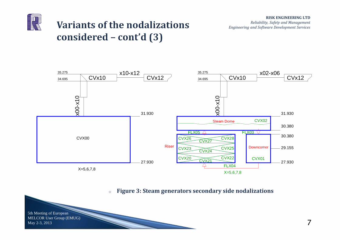
o To discuss the results from sensitivity studies which are performed in order to be analyzed WWER-1000 plant model response during severe accident progression when two different MELCOR 2.1 nodalizations for the steam generators secondary side are used. These two nodalizationsare respectively with one and three hydrodynamic volumes for the steam generators secondary side;
o To represent and discuss various MELCOR 2.1 and/or plant model issues which have been identified during the performance of the sensitivity studies.
5th Meeting of European MELCOR User Group (EMUG)May 2-3, 2013 3

RISK ENGINEERING LTD
Reliability, Safety and Management
Engineering and Software Development Services
The nodalization schemes for the reactor pressure vessel and reactor
internals, the primary loops and the steam generators secondary side are
shown on Figure 1, Figure 2 and Figure 3 respectively.
5th Meeting of European MELCOR User Group (EMUG)May 2-3, 2013 4

RISK ENGINEERING LTD
Reliability, Safety and Management
Engineering and Software Development Services
5th Meeting of European MELCOR User Group (EMUG)May 2-3, 2013
010-020010-020010-020
CV013
CV035
CV046
CV032
CV037
CV034
CV055
CV050
CV027
CV054CV014
CV026
CV025
CV033
CV024
CV053CV043CV023
CV056
CV044
CV022CV012
CV047
CV042
CV016
CV057
CV045
CV017
CV052
CV036
CV015
CVX00
CVX09(CV110*)
CV
040
X=1,2,3,4
035-060034-060
033-060032-060
031-060 027-060
057-050
x09-010 (110-010*)
29,440
035-040
CVX09(CV110*)
16.899
18.519
060-070
070-050
18.419
040-060
24.930
020-040
22.928
020
-06
0
CV020
CV
040
CV070
CV050CV091
CV
060
CV
010
22.928047-060
CV
032
033-034 031-032034-035 032-033
035-040
23.728
CV
031
CV
033
091-092
057-060
047-050
CV
034
CV
035
CV092
020-031020-040
26.753
020-032020-033
020
-06
0
020-034020-035
050-091
24.647
040-050
040-060 040-050
070-092
037-060
CV
010
CV
060
CV070
031-050032-050
020-012
033-050034-050
16.899
035-050
050-x00
020-022
017-050
24.930
x09-010 (110-010*)
CVX00
29,440
CVX09(CV110*)
16.899
26.953 26.953
020-032
030-060
18.519
020-040
020-030
060-070
070-050
18.419
060-070
020-042
027-050
24.930
040-050
020
-06
0
040-060
29,440
030-050
CV030
CV020
CV
040
020-052
CV070
CV050CV
060
CV
010
18.519
030-040
050-x00
x09-010 (110-010*)
22.928
CV020
017-060
037-050
050-x00 CVX00
o Figure 1: Reactor pressure vessel and reactor internals nodalizations (for all the
cases 5 radial rings in the COR package are modeled)
5

RISK ENGINEERING LTD
Reliability, Safety and Management
Engineering and Software Development Services
5th Meeting of European MELCOR User Group (EMUG)May 2-3, 2013
o Figure 2: Primary loops nodalization (4 separate loops are modeled)
x05-x06
x00-x04
25.275
CV
x01
CV
x05
32,17
x24-x25
x06-x07
x26-x27
x07-x08
x23-x24
22,18
CVx23
x20-x21CV
x02
CV
x03
x21-x22
x27-x28
109-110*
26.125
23.475
x04-x05
CVx25
CV
x08
CVx27
CVx00
24.000
30,128
29.140
x28-x05
20,215 20,215
CV
x06
32,17
29.140
CV
x04
CVx09
30,128
27,93827,938
24.325
x25-x05
x01-x02
CVx28
CVx20
x02-x23
CVx26
CVx07
23.900
x08-x09
x02-x26
CVx21 CVx22
CVx24
25.700
20,640
x02-x03
CV110
x22-x05x02-x20
21,065
23.900x09-010 (110-010*)
25.700050-x00
28,0395
28.7565
29.5545
CV050
CV010
CV458CV458
110-458 109-458
X=1,2,3,4
6
RISK ENGINEERING LTD
Reliability, Safety and Management
Engineering and Software Development Services
5th Meeting of European MELCOR User Group (EMUG)May 2-3, 2013
o Figure 3: Steam generators secondary side nodalizations
CVX28
CVX24
CVX27
CVX01CVX22
CVX02
CVX25
FLX03
CVX20
FLX05
FLX04
CVX23
X=5,6,7,8
CVX21
CVX26
Riser
Steam Dome
Downcomer
CVX00
CVx12
x00-
x10
CVx10x0
0-x1
0
X=5,6,7,8
x10-x12CVx10 CVx12
x02-x06
29.155
30.380
31.930
35.275
34.695
35.275
30.380
27.930
34.695
31.930
27.930
7

RISK ENGINEERING LTD
Reliability, Safety and Management
Engineering and Software Development Services
For the performance of the sensitivity studies, the following conditions and assumptions take place:
o Subversion 5026 of MELCOR 2.1 has been used for the calculations;
o For the flow paths which connect the reactor lower plenum to the reactor core, flow paths inside the core, flow path to the reactor core bypass and the artificial flow paths between the core and the core shroud, the flow blockage option has been activated (FL_BLK). The default value of the minimum porosity which is used in calculation of the flow resistance is chosen. The exception of that assumption is a case with double ended break of a main circulation pipeline (case 3B from Table 2) for which this coefficient is set to 0.5 in order to avoid failure of MELCOR 2.1;
o No safety systems are available with the exception of the case with reactor pressure vessel bottom break (as initiating event);
o HS degasing option is activated (HS_DG) – for the steel structures inside the vessel;
o No operator actions are considered.
5th Meeting of European MELCOR User Group (EMUG)May 2-3, 2013 8

RISK ENGINEERING LTD
Reliability, Safety and Management
Engineering and Software Development Services
For the purposes of sensitivity studies, the following cases have been selected: o Total loss of power supply to the unit – For WWER-1000 (V320) this transient
is characterized by high primary pressure and relatively slow primary water inventory decrease. Input decks with 1, 5 and 30 volumes in the reactor core are used. One and three volumes for the steam generators secondary side are separately used;
o Double ended break of a main circulation pipeline with DN 2x850 mm (cold leg break) – this case is characterized by the most dynamic change in the primary side parameters and very fast degradation of the core in case of unavailability of safety systems. Input decks with 1, 5 and 30 volumes in the reactor core are used. One volume for the steam generators secondary side is used because the secondary side influence on the severe accident progression for that case is not expected to be significant;
o Reactor pressure vessel partial break with DN 1130 mm (cross section area around 1.0 m2) with active and passive safety systems availability – this case is analyzed in order to assess the core blockage behavior for 1, 5 and 30 volumes in the reactor core region with safety systems availability. One volume for the steam generators secondary side is used, because the secondary side influence on the severe accident progression for that case is not expected to be significant;
5th Meeting of European MELCOR User Group (EMUG)May 2-3, 2013 9

RISK ENGINEERING LTD
Reliability, Safety and Management
Engineering and Software Development Services
o Middle LOCA of a cold circulation pipeline (close to the reactor vessel) with
DN60 mm – this case is analyzed in order to assess the reactor installation
response in case of severe accident progression as a result of middle LOCA.
Input decks with 1, 5 and 30 volumes in the reactor core are used. One and
three volumes for the steam generators secondary side are separately used;
o Primary to secondary LOCA with DN 43 mm (PRISE 43 mm) – this case is
specifically analyzed in order to be assessed the secondary side influence on
the primary parameters in severe accident conditions.
Summary information for the cases which have been selected for the sensitivity
studies is presented in Table 1.
5th Meeting of European MELCOR User Group (EMUG)May 2-3, 2013 10

RISK ENGINEERING LTD
Reliability, Safety and Management
Engineering and Software Development Services
5th Meeting of European MELCOR User Group (EMUG)May 2-3, 2013
CaseCaseCaseCaseInitial Initial Initial Initial
ConditionConditionConditionConditionSafety systems Safety systems Safety systems Safety systems
availabilityavailabilityavailabilityavailabilityVariantVariantVariantVariant
Number of Number of Number of Number of Core/SG Core/SG Core/SG Core/SG volumesvolumesvolumesvolumes
1. Station blackout Nominal Power No
1A 1V/1V
2A 5V/1V
3A 30V/1V
4A 30V/3V
2. LB LOCA with DN2x850 mm
Nominal Power No
1B 1V/1V
2B 5V/1V
3B 30V/1V
3. RPV bottom partial failure with DN 1130
mmNominal Power
Yes (one train from each safety
system)
1C 1V/1V
2C 5V/1V
3C 30V/1V
4. MB LOCA with DN60 mm
Nominal Power No
1D 1V/1V
2D 5V/1V
3D 30V/1V
4D 30V/3V
5. PRISE with DN43 mmNominal Power No
1E 30V/1V
2E 30V/3V
Table 1: Summary information for the cases analyzed
11

RISK ENGINEERING LTD
Reliability, Safety and Management
Engineering and Software Development Services
For the sensitivity studies performed, the following parameters during the severe accident progression are analyzed: o CPU time consumption (tCPU) – up to the moment of vessel breach;
o Total amount of hydrogen generated in the reactor core (COR-DMH2-TOT);
o Onset of gap release (tGR);
o Time when the maximal fuel cladding temperature reaches 1200oC (tCD);
o Onset of reactor core degradation (tDEG);
o Onset of UO2 relocation into the reactor lower plenum (tMUO2);
o Total mass of UO2 relocated into the lower plenum before the vessel breach (MUO2);
o Onset of the reactor pressure vessel breach (tVBR);
o Total amount of molten material ejected to the reactor cavity (COR-MEJEC-TOT);
o Maximal temperature of the hot legs (Thl_max) – important for station blackout scenarios due to the creep rupture phenomenon (it is assessed 30 min before the vessel breach because HPME/DCH is concurrent to the creep rupture phenomenon);
5th Meeting of European MELCOR User Group (EMUG)May 2-3, 2013 12

RISK ENGINEERING LTD
Reliability, Safety and Management
Engineering and Software Development Services
5th Meeting of European MELCOR User Group (EMUG)May 2-3, 2013
CaseCaseCaseCase VariantVariantVariantVariant
Number Number Number Number of of of of
Core/SG Core/SG Core/SG Core/SG volumesvolumesvolumesvolumes
CORCORCORCOR----DMH2DMH2DMH2DMH2----
TOTTOTTOTTOT
[kg][kg][kg][kg]
tCPUtCPUtCPUtCPU
[h][h][h][h]
tStZrtStZrtStZrtStZr
[s][s][s][s]
tGRtGRtGRtGR
[s][s][s][s]
tCDtCDtCDtCD
[s][s][s][s]
tDEGtDEGtDEGtDEG
[s][s][s][s]
1. Station blackout
1A 1V/1V 582 10.8 10500 10946 12500 154302A 5V/1V 912912912912 11.3 11500 11691 15000 244352443524435244353A 30V/1V 760 16.9 11000 11347 13000 158444A 30V/3V 668 17.5 10500 10727 12500 14997
2. LB LOCA with DN2x850
mm
1B 1V/1V 114 10.1 5 40 160 8002B 5V/1V 149 10.0 5 45 160 800
3B 30V/1V 131 19.8 5 47 240 720
3. RPV bottom partial failure with DN 1130
mm
1C 1V/1V 95 108 6 48 175 797
2C 5V/1V 208 157 6 48 175 807
3C 30V/1V 2.3 331* 120 278 NONONONO NONONONO
4. MB LOCA with DN60
mm
1D 1V/1V 273 11.2 2000 1800 2500 28262D 5V/1V 263 9.8 2000 2000 2500 33413D 30V/1V 295 16.5 2000 2077 2500 31134D 30V/3V 246 17.4 2000 2038 2500 3067
5. PRISE with DN43 mm
1E 30V/1V 454 22.3 8000 8417 9500 105762E 30V/3V 401 22.9 8000 8242 9500 10271
Table 2: Summary results from the sensitivity studies performed – part 1
*Calculated to the 24-th h (accident progression time) after the accident initiation
13

RISK ENGINEERING LTD
Reliability, Safety and Management
Engineering and Software Development Services
5th Meeting of European MELCOR User Group (EMUG)May 2-3, 2013
Table 2: Summary results from the sensitivity studies performed – part 2
CaseCaseCaseCase VariantVariantVariantVariantNumber of Number of Number of Number of Core/SG Core/SG Core/SG Core/SG volumesvolumesvolumesvolumes
tMUO2tMUO2tMUO2tMUO2
[s][s][s][s]
MUO2MUO2MUO2MUO2
[tons][tons][tons][tons]
Thl_maxThl_maxThl_maxThl_max********
[K][K][K][K]
tVBRtVBRtVBRtVBR
[s][s][s][s]
CORCORCORCOR----MEJECMEJECMEJECMEJEC----
TOTTOTTOTTOT
[tons][tons][tons][tons]
1. Station blackout
1A 1V/1V 15684 69 1260126012601260 25236 1952A 5V/1V 24490244902449024490 52 1428142814281428 25615 2183A 30V/1V 16389 63 1015 22351 2224A 30V/3V 15946 53 994 20525 194
2. LB LOCA with DN2x850 mm
1B 1V/1V 1940 77 Not needed 8166 154
2B 5V/1V 2470 74 Not needed 9024 178
3B 30V/1V 2480 78 Not needed 7983 157
3. RPV bottom partial failure with DN 1130
mm
1C 1V/1V 797 83 Not needed 22350223502235022350 144
2C 5V/1V 9208 76 Not needed 40500405004050040500 114
3C 30V/1V NO NO Not needed NONONONO NONONONO
4. MB LOCA with DN60 mm
1D 1V/1V 5704 70 Not needed 12845 186
2D 5V/1V 4290 77 Not needed 14936 173
3D 30V/1V 5923 72 Not needed 12057 156
4D 30V/3V 5506 76 Not needed 13258 162
5. PRISE with DN43 mm
1E 30V/1V 10698 66 Not needed 17972 194
2E 30V/3V 10422 70 Not needed 18235 180
14

RISK ENGINEERING LTD
Reliability, Safety and Management
Engineering and Software Development Services
5th Meeting of European MELCOR User Group (EMUG)May 2-3, 2013
o Figure 4: Total amount of the hydrogen generated for the in-vessel phase of severe accident (cases A, B,)
0
100
200
300
400
500
600
700
800
900
1000
0 10000 20000 30000 40000 50000 60000
Mass
[kg
]
Time [s]
COR-DMH2-TOT_1ACOR-DMH2-TOT_2ACOR-DMH2-TOT_3ACOR-DMH2-TOT_4A
0
20
40
60
80
100
120
140
160
0 10000 20000 30000 40000 50000
Ma
ss
[k
g]
Time [s]
COR-DMH2-TOT_1B
COR-DMH2-TOT_2B
COR-DMH2-TOT_3B
15

RISK ENGINEERING LTD
Reliability, Safety and Management
Engineering and Software Development Services
5th Meeting of European MELCOR User Group (EMUG)May 2-3, 2013
o Figure 5: Total amount of the hydrogen generated for the in-vessel phase of severe accident (cases D, E)
0
50
100
150
200
250
300
0 20000 40000 60000 80000 100000
Ma
ss
[k
g]
Time [s]
COR-DMH2-TOT_1DCOR-DMH2-TOT_2DCOR-DMH2-TOT_3DCOR-DMH2-TOT_4D
0
50
100
150
200
250
300
350
400
450
500
0 20000 40000 60000 80000 100000
Ma
ss
[k
g]
Time [s]
COR-DMH2-TOT_3E
COR-DMH2-TOT_4E
16

RISK ENGINEERING LTD
Reliability, Safety and Management
Engineering and Software Development Services
5th Meeting of European MELCOR User Group (EMUG)May 2-3, 2013
o Figure 6: Total amount of the hydrogen generated –RELAP/SCDAP – Mass (tons) vs. Time (s) [2]
17

RISK ENGINEERING LTD
Reliability, Safety and Management
Engineering and Software Development Services
5th Meeting of European MELCOR User Group (EMUG)May 2-3, 2013
o Figure 7: Maximal gas temperature in the core – station blackout cases
18
500
1000
1500
2000
2500
3000
10000 12000 14000 16000 18000 20000 22000 24000 26000 28000 30000
Tem
per
atu
re[K
]
Time [s]
CFVALU_2357_1V1VCFVALU_2357_5V1VCFVALU_2357_30V1VCFVALU_2357_30V3V
0
500
1000
1500
2000
2500
3000
0 10000 20000 30000 40000 50000 60000
Tem
per
atu
re[K
]
Time [s]
CFVALU_2357_1V1VCFVALU_2357_5V1VCFVALU_2357_30V1VCFVALU_2357_30V3V

RISK ENGINEERING LTD
Reliability, Safety and Management
Engineering and Software Development Services
5th Meeting of European MELCOR User Group (EMUG)May 2-3, 2013
o Figure 8: Hot legs gas temperatures (left) and hot legs metal temperature (right)
19
400
600
800
1000
1200
1400
1600
1800
0 10000 20000 30000 40000 50000 60000
Tem
per
atu
re[K
]
Time [s]
CVH-TVAP_400_1V1VCVH-TVAP_400_5V1VCVH-TVAP_400_30V1VCVH-TVAP_400_30V3V 400
600
800
1000
1200
1400
1600
0 10000 20000 30000 40000 50000 60000
Tem
per
atu
re[K
]
Time [s]
HS-TEMP_1V1VHS-TEMP_5V1VHS-TEMP_30V1VHS-TEMP_30V3V

RISK ENGINEERING LTD
Reliability, Safety and Management
Engineering and Software Development Services
Issue 1: Related to station blackout scenario (5 volumes in the core
region):
When nodalization scheme with 5 volumes in the core is used, then the core
degradation starts immediately after the vessel breach or very late after that
moment which is not physically accurate. This leads to initial ejection of a very
small amount of molten material (mainly steel – about 500 kg) and the peak of
the molten corium ejection starts about 4000 s after the vessel breach (see COR-
MEJEC-TOT_2B_1 on Figure 9). The root cause of that issue might be related to
erroneous activation of the lower head mechanical model (by the code or due to
user mistakes). It is not clear so far what the exact reason is.
5th Meeting of European MELCOR User Group (EMUG)May 2-3, 2013 20

RISK ENGINEERING LTD
Reliability, Safety and Management
Engineering and Software Development Services
This issue has been overcome by the following ways:
o The lower head mechanical model is switched off by the sensitivity coefficient
1600 (3) which is set to 1.0E10. When the molten core material in the lower
plenum reaches around 50-70 tons and there is molten material into the lower
plenum region below the barrel perforated bottom (around 2.5 t), then SC
1600 (3) is set back to its default value of 1.0E3. The lower head fails and the
molten corium ejection seems to be quite reasonable (see COR-MEJEC-
TOT_2B_2 on Figure 9). For Variant 2A (from Table 2) this approach has been
applied;
o Nodalization scheme with 30 hydrodynamic volumes in the core – for that
nodalization this issue does not appear at all.
5th Meeting of European MELCOR User Group (EMUG)May 2-3, 2013 21

RISK ENGINEERING LTD
Reliability, Safety and Management
Engineering and Software Development Services
Depending on the time step this issue might cause additional problems
such as:
o Reactor vessel breach with a very small amount of corium ejected – 1.0E-38 kg
followed by a large corium ejection several hundred seconds after the vessel
breach;
o Generation of error massage: Cavity Overfilled (an attempt to be ejected
physically impossible amount of molten material – around 900 tons). This
used to happen for the MELCOR 2.1 subversions before subversion 5026 for
our WWER-1000 plant model specifically.
5th Meeting of European MELCOR User Group (EMUG)May 2-3, 2013 22

RISK ENGINEERING LTD
Reliability, Safety and Management
Engineering and Software Development Services
5th Meeting of European MELCOR User Group (EMUG)May 2-3, 2013
o Figure 9: Mass of molten corium ejected – left hand side (close plan)
23
0
200
400
600
800
1000
1200
1400
1600
1800
2000
20000 22000 24000 26000 28000 30000
Mas
s [k
g]
Time [s]
COR-MEJEC-TOT_2B_1
COR-MEJEC-TOT_2B_2
0
50000
100000
150000
200000
250000
20000 30000 40000 50000 60000
Mas
s [k
g]
Time [s]
COR-MEJEC-TOT_2B_1
COR-MEJEC-TOT_2B_2

RISK ENGINEERING LTD
Reliability, Safety and Management
Engineering and Software Development Services
Issue 2: Related to station blackout scenario (5 and 30 volumes in the
core region):
When nodalization scheme with 5 or 30 volumes in the core is used, then, at the
moment of the reactor pressure vessel breach, the primary pressure oscillation
between 14 MPa and 20 MPa occurred (see CVH-P_20_A on Figure 10). It is
followed by a message for lowed head failure due to overpressure. This issue has
been overcome by the following ways:
o 500-1000 s before the vessel breach the sensitivity coefficient 1505 (1) was
set to 1.0 (core blockage porosity coefficient) (see CVH-P_20_B on Figure 10);
o When 3 volumes for the steam generators are used then this issue does not
appear at all.
5th Meeting of European MELCOR User Group (EMUG)May 2-3, 2013 24

RISK ENGINEERING LTD
Reliability, Safety and Management
Engineering and Software Development Services
5th Meeting of European MELCOR User Group (EMUG)May 2-3, 2013
o Figure 10: Reactor lower head pressure before and shortly after
the vessel breach
13
14
15
16
17
18
19
20
22200 22250 22300 22350 22400
Pre
ssu
re [
MP
a]
Time [s]
CVH-P_20_A
CVH-P_20_B
25

RISK ENGINEERING LTD
Reliability, Safety and Management
Engineering and Software Development Services
Issue 3: Related to LB LOCA with DN 2x850 mm (30 volumes in the core
region)
o When nodalization scheme with 30 volumes in the core is used then a very
large temperature peak around 10 000 K in a volume from the core region
occurs and therefore MELCOR 2.1 fails (see CFVALU_2357_0.05 on Figure 11).
This issue is overcome by setting sensitivity coefficient 1505 (1) to 0.5. Values
of that coefficient equal to 0.05 (by default), 0.1 and 0.25 lead to high
temperature peak in the core and code failure.
5th Meeting of European MELCOR User Group (EMUG)May 2-3, 2013 26

RISK ENGINEERING LTD
Reliability, Safety and Management
Engineering and Software Development Services
5th Meeting of European MELCOR User Group (EMUG)May 2-3, 2013
o Figure 11: Maximal gas temperatures in the core for Issue 3
(right) – blockage porosity 0.05, 0.25 and 0.5
0
1000
2000
3000
4000
5000
6000
7000
8000
9000
10000
11000
600 800 1000 1200 1400
Tem
per
atu
re[K
]
Time [s]
CFVALU_2357_0.05
CFVALU_2357_0.25
CFVALU_2357_0.5
27

RISK ENGINEERING LTD
Reliability, Safety and Management
Engineering and Software Development Services
Issue 4: Related to RPV bottom partial failure with DN 1130 mm (all
variants);
For that initiating event, quite unexpected results have been obtained. For the
variant with 1 and 5 hydrodynamic volumes in the core, the reactor vessel breach
occurs about 22350 s and 40500 s after the accident initiation respectively (see
Figure 12 (left hand side)). For the case with 30 volumes, core degradation does
not occur at all (to ensure that, the calculation is extended to 24h) (see Figure 12
(right hand side)). At that moment, no reasonable explanation for these results
has been found.
5th Meeting of European MELCOR User Group (EMUG)May 2-3, 2013 28

RISK ENGINEERING LTD
Reliability, Safety and Management
Engineering and Software Development Services
5th Meeting of European MELCOR User Group (EMUG)May 2-3, 2013
o Figure 12: Mass of molten corium ejected (left) and maximal fuel
cladding temperature (right) for Issue 4
0
20
40
60
80
100
120
140
160
0 50000 100000 150000 200000 250000 300000
Ma
ss [
ton
s]
Time [s]
COR-MEJEC-TOT_1C
COR-MEJEC-TOT_2C
0
500
1000
1500
2000
2500
3000
0 20000 40000 60000 80000 100000
Tem
pe
ratu
re[K
]Time [s]
CFVALU_9017_1CCFVALU_9017_2CCFVALU_9017_3C
29

RISK ENGINEERING LTD
Reliability, Safety and Management
Engineering and Software Development Services
As a result of the sensitivity studies performed, the following conclusions can be drawn: o The general progression of the severe accident for most of the cases considered is
reasonable. The exceptions are the cases with RPV bottom break (with DN 1130 mm). The obtained results are quite different and it is difficult to draw a clear conclusion about them. This causes great uncertainty in the containment event trees development for these cases;
o Most of the issues which have been identified are related to the nodalization schemes with 5 and 30 hydrodynamic volumes into the core region;
o The variants with 1 hydrodynamic volume in the core have not caused any issues and the code run quite stable. This variant leads to the lowest amount of hydrogen generated for the in-vessel phase of the severe accident in case of station blackout scenario (case 1A). According to the results for the same initiating event which are generated by RELAP/SCDAP, the total amount of hydrogen generated for that phase is around 800 kg (see Figure 6). So the lowest amount of hydrogen for that case may or may not be physically accurate. As it can be seen from Table 2, the COR-DMH2-TOT parameter for cases 2A ÷ 4A is significantly higher than in case 1A which can be explained by the possibility for in-core circulation of water-steam mixture and the different core blockage behavior (more volumes and more flow paths available in the core for 5 and 30 volumes nodalizations). For case 2A, the largest value for the COR-DMH2-TOT parameter comes from the latest core relocation into the lower head and therefore latest vessel breach;
5th Meeting of European MELCOR User Group (EMUG)May 2-3, 2013 30

RISK ENGINEERING LTD
Reliability, Safety and Management
Engineering and Software Development Services
o For LB LOCA with DN 2x850 mm, MB LOCA with DN 60 mm and PRISE 43 mm, the
total amount of hydrogen generated into the core during the in-vessel phase does not
differ significantly for the nodallizations with 1, 5 and 30 volumes in the core. Variant
3B is characterized by physically impossible gas temperature behavior in the core
when the minimal blockage fraction is less than 0.5;
o For the cases 1A and 1B, the maximal hot legs metal temperatures are significantly
higher than in cases 1C and 1D. This result is important when one considers creep
rupture phenomenon which is more likely to occur for the hot legs than for the
pressurizer surge line or SG tube (in the cases where none of the loop seals is
cleared);
5th Meeting of European MELCOR User Group (EMUG)May 2-3, 2013 31

RISK ENGINEERING LTD
Reliability, Safety and Management
Engineering and Software Development Services
1) Actualization of PSA level 2 for KNPP (Kozloduy NPP, Bulgaria) units 5 and
6 (full power and shut-down), Risk Engineering Ltd (project is in
progress);
2) Accident Management Guidelines and Procedures: Improvement of the
Emergency Documentation for Ukrainian NPP, Risk Engineering Ltd.
(project is in progress)
5th Meeting of European MELCOR User Group (EMUG)May 2-3, 2013 32

RISK ENGINEERING LTD
Reliability, Safety and Management
Engineering and Software Development Services
5th Meeting of European MELCOR User Group (EMUG)May 2-3, 2013 33
Headquarters:
10, Vihren str.
Sofia 1618
Bulgaria
Tel. + 359 2 8089 703
Fax: +359 2 9507 751
www.riskeng.bg
CONTACT DETAILS

RISK ENGINEERING LTD
Reliability, Safety and Management
Engineering and Software Development Services
THANK YOU!
5th Meeting of European MELCOR User Group (EMUG)May 2-3, 2013 34