
Event Driven Electronic Circuit Construction - Atelier B
42
Transcript of Event Driven Electronic Circuit Construction - Atelier B
Event Driven Electronic Circuit Construction
by J.-R. Abrial
August 2001
Version 5
Event Driven Electronic Circuit Constrution
1. Introduction
In this paper, I shall present a simple methodology supporting the progressive proved development of synchro-nized circuits. For this, I shall use the B Method [1] and, more precisely, its, so-called, event-driven approach[2] [3]. Some examples illustrate the presentation: they are entirely mechanically treated with Atelier B, whichis the tool associated with B. Another outcome of this paper is the notion of design by proof: we shall see howthe proofs, done during the design process of our circuits, will de�nitely in uence it.
1.1 Synchronized Circuits
A synchronized circuit is viewed as a box, within which an input line is entering, and out of which an outputline is emerging. Of course, there might be more input and output lines.
+===========+
input ! ! output
----->-----! box !----->-----
! !
+===========+
Fig. 1. A typical circuit
The circuit is supposed to be synchronized by a clock, which pulses regularly between two alternativepositions: low and high
+---+ +---+ +---+ +---+ +---+ +---+ high
| | | | | | | | | | | |
- - ---+ +---+ +---+ +---+ +---+ +---+ +--- - - low
Fig. 2. Clock pulses
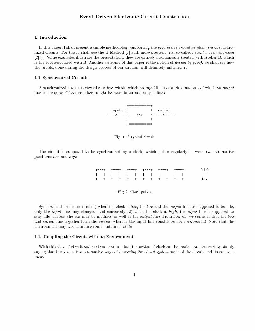
Synchronization means this: (1) when the clock is low, the box and the output line are supposed to be idle,only the input line may changed, and conversely (2) when the clock is high, the input line is supposed tostay idle whereas the box may be modi�ed as well as the output line. From now on, we consider that the boxand output line together form the circuit, whereas the input line constitutes its environment. Note that theenvironment may also comprise some \internal" state.
1.2. Coupling the Circuit with its Environment
With this view of circuit and environment in mind, the notion of clock can be made more abstract by simplysaying that it gives us two alternative ways of observing the closed system made of the circuit and its environ-ment.
1
We can thus consider that we have two modes of observation: one, env, corresponds to observing the envi-ronment independently from the circuit, and another one, cir, consisting in observing the circuit independentlyfrom the environment. Such modes alternate for ever. From now on, we shall follow that view and forget aboutthe clock. This has the consequence that we shall never develop a circuit in isolation, but always together withits environment. Such a coupling is shown in the following schema:
environment circuit
_____________________ _______________________
/ \ / \
+===========+ +===========+
! ! input ! ! output
+--! state !----->-----! box !----->-----+
| ! ! ! ! |
| +===========+ +===========+ |
+--------------------<-----------------------------+
Fig. 3. A circuit coupled with its environment
1.3. Dynamic View of the Coupling
There is an important distinction to be made between the way the input line and environmental state arechanged when the mode is env, and the output line and box are changed when the mode is cir. The modi�cationof the environment may follow some speci�c rules but in no case is it in uenced by the box (it may be in uencedby the output however). Conversely, the change in the circuit may depend on the input line and on the box(but not on the state of the environment however). This can be formalized by the following \non-deterministicassignments":
mode = env =)
�state; input :2 F (output; state) kmode := cir
�
mode = cir =)
�box; output :2 G(input; box) kmode := env
�
The conditions mode = env or mode = cir situated on the left hand side of the long arrow \=)" are theguards of these assignments: they represent the necessary conditions for the multiple assignments situated onthe right hand side of \=)" to be \executed". The symbol \:2" is a non-deterministic generalization of theclassical assignment symbol \:=". The symbol \k" corresponds to a generalization of multiple assignment.What is formalized here is just \one step" of the alternating behaviors of the environment and of the circuit.
The formula F (output; state) above represents the set of possible next values for the environment (dependingon the output of the circuit and the state of the environment), it speci�es the way the environment may evolve:it must clearly be totally outside the control of the box of the circuit. This assignment is non-deterministicbecause, most of the time, the environment moves in a way that cannot be known in advance (although nottotally erratically). Notice that a possibility is one by which the environement stays unchanged. Another possi-bility is one by which the environement is not in uenced by the output of the circuit: in this case, the coupling
2

between the two is rather loose.
Likewise, the formula G(input; box) represents the set of possible next values for the circuit (depending oninput and on the previous value of box). It speci�es the way the circuit reacts to the uncontrolled behavior ofits environment and possibly to its own past (represented by its internal status box). Here the assignment mightbe non-deterministic because, in an abstract view of the circuit, we do not need to make its behavior completelyknown in all circumstances: we can accept a certain laxism in the speci�cation, leaving the �nal details of variousalternative implementations for a further design phase. Notice that, as for the environment, one of the variouspossibilities is that the circuit does not change: in this case, it simply is reactionless in front of the environment.
Also notice that, in an abstract view of our circuit and environment, the status of the input and output linesand of box and state are not necessarily represented by boolean values (which will probably be the case in are�ned implementation). For instance, in an abstract speci�cation, state can very well carry the entire historyof what has happened since the interaction between the circuit and its environment has started.
1.4. Static View of the Coupling
So far we have only envisaged a very operational (although abstract) view of our circuit and environment:we have just described how these entities behave dynamically while time is passing, but we have not at allexplained why they should behave like this. Another completely independant approach is one by which a staticview is presented by means of some conditions C and D describing the way these entities are permanentlyrelated to each others. These conditions express the way the circuit is coupled with its environment.
mode = env ) C((state; input); (box; output))
mode = cir ) D((state; input); (box; output))
Condition C states what the circuit should establish (for the environment) provided it behaves in a situationwhere D holds. Conversely, condition D states what the environment should establish (for the circuit) providedit behaves in a situation where C holds.
1.5. Consistency Conditions
Nothing guarantees however that the dynamics envisaged above and the statics we have just described arecoherent: this is something that has to be proved rigorously. It can be stated as follows:
C( (state; input); (box; output) ) ^ (s0; i0) 2 F (output; state) ) D( (s0; i0); (box; output) )
D((state; input); (box; output)) ^ (b0; o0) 2 G(input; box) ) C( (state; input); (b0; o0) )
Informally, this means that when mode is env and the static condition C holds, then D must hold after anyaccepted modi�cations s0 and i0 of state and input made by the environment. Likewise, when mode is cir andthe static condition D holds, then C must hold after any accepted modi�cations o0 and b0 of output and box
made by the circuit.
3

1.6. Decomposing the Circuit and the Environment
The above statements to prove are rather heavy because of the inherent non-determinacy. The idea is then todecompose the behaviors of each partner (environment and circuit) in various independant deterministic pieces,which we call events. For instance, the non-determinitic behavior of the partners can be decomposed in thefollowing deterministic events, where conditions P1(output; state), : : : , denotes the guards of the environmentalevents, whereas Q1(input; box), : : : denotes the guards of the circuit events:
Environment
8<:mode = env ^ P1(output; state) =) state; input;mode := F1(output; state); cir
: : :
Circuit
8<:mode = cir ^ Q1(input; box) =) box; ouput;mode := G1(input; box); env
: : :
Notice that the P guards may overlap, thus leading to the non-determinacy of the environment. Likewise,the Q guards may overlap, hence the non-determinacy of the circuit.
1.7 Consistency Conditions Revisited
Our consistency conditions are now transformed in the following collection of more tractable formulae:
C( (state; input); (box; output) ) ^ P1(output; state) ) D(F1(output; state); (box; output) ): : :
D( (state; input); (box; output) ) ^ Q1(input; box) ) C( (state; input); G1(input; box) ): : :
1.8. A Warning
Note that this formulation corresponds to what we must obtain towards the end of a formal developmentwhere there should exist a very clear distinction between the circuit and the environment. During the devel-opment however, such a distinction is not necessarily as strict. For instance, we might allow for the possibilityof the environment to access the previous input and even to access the box of the circuit. Likewise, we acceptto have the circuit accessing its previous output and even the entire state of the environment. What must stillbe clearly followed however, even in an abstraction, is the limitation of modi�cation: the environment modi�esthe input and the state only, whereas the circuit modi�es the box and the output only.
One of the objective of the design of a circuit is precisely that of making the circuit and environment om-municating eventually through the input and output lines only. For this, we have to localize their respectivestates.
2. A First Illustrating Example
As the previous discussion may appear to be rather dry, we shall now illustrate our approach by describinga little example of circuit speci�cation and design.
4

2.1. Speci�cation
The circuit we propose to study is a well-known benchmark that has been analysed in di�erent contexts: itis called the Single Pulser (Pulser for short). Here is a �rst informal speci�cation taken from [4]:
We have a debounced push-button, on (true) in the down position, o� (false) in the up position. Devisea circuit to sense the depression of the button and assert an output signal for one clock pulse. Thesystem should not allow additional assertions of the output until after the operator has released thebutton.
Here is another related speci�cation [4], which is given under the form of three properties concerning the inputI and the output O of the circuit:
1. Whenever there is a rising edge at I, O becomes true some time later.
2. Whenever O is true it becomes false in the next time distance and it remains false at least until thenext rising edge on I.
3. Whenever there is a rising edge, and assuming that the output pulse doesn't happen immediately,there are no more rising edges until that pulse happens (There can't be two rising edges on I without apulse on O between them).
My subjective impression after reading these speci�cations is that they are rather di�cult to understand.I'd prefer to plunge the circuit to specify within a possible environment as follows:
1. We have a button that can be depressed and released by an operator. The button is connected tothe input of the circuit.
2. We have a lamp that is able to be lit and subsequently turned down. The lamp is connected to theoutput of the circuit.
3. The circuit, situated between the button and the lamp, must make the lamp always ashing as manytimes as the button is depressed and subsequently released.
Here is a schematic representation of this closed system.
BUTTON LAMP / \
_________ | |
_____| ___ |_____ \ /
| |_|
| |
| +============+ |
| input ! ! output |
+----->-----! PULSER !----->-----+
! !
+============+
Fig. 4. The Pulser circuit in its environment
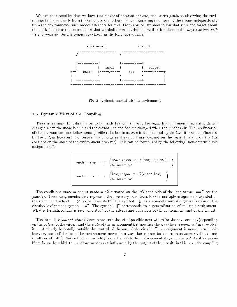
Note that the scenario we have described can be observed by an external witness: we can count the numberof times the button is depressed by the operator and also the number of times the lamp ashes and we can
5
compare these numbers. For example, the following schemata shows two wave diagrams: the �rst one representsa succession of releases and subsequent depressions of the button, and the second shows various corresponding ashes of the lamp.
+--------------+ +---------+ +------+ depressed
BUTTON | | | | | |
-----+ +-------+ +----------+ +--- released
+-+ +-+ +-+
LAMP | | | | | | flashes
----------+ +--------------------+ +---------------+ +------
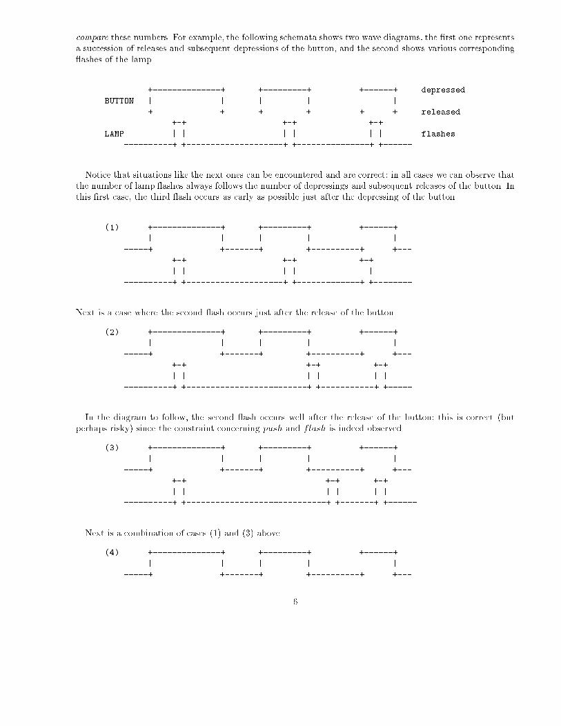
Notice that situations like the next ones can be encountered and are correct: in all cases we can observe thatthe number of lamp ashes always follows the number of depressings and subsequent releases of the button. Inthis �rst case, the third ash occurs as early as possible just after the depressing of the button
(1) +--------------+ +---------+ +------+
| | | | | |
-----+ +-------+ +----------+ +---
+-+ +-+ +-+
| | | | | |
----------+ +--------------------+ +-------------+ +--------
Next is a case where the second ash occurs just after the release of the button
(2) +--------------+ +---------+ +------+
| | | | | |
-----+ +-------+ +----------+ +---
+-+ +-+ +-+
| | | | | |
----------+ +-------------------------+ +-----------+ +-----
In the diagram to follow, the second ash occurs well after the release of the button: this is correct (butperhaps risky) since the constraint concerning push and flash is indeed observed.
(3) +--------------+ +---------+ +------+
| | | | | |
-----+ +-------+ +----------+ +---
+-+ +-+ +-+
| | | | | |
----------+ +-----------------------------+ +-------+ +------
Next is a combination of cases (1) and (3) above.
(4) +--------------+ +---------+ +------+
| | | | | |
-----+ +-------+ +----------+ +---
6

+-+ +-+ +-+
| | | | | |
----------+ +-----------------------------+ +----+ +--------
In the next case, the second ash occurs at the last possible moment. How does the lamp know that it hasto ash now? Not clear.
(5) +--------------+ +---------+ +------+
| | | | | |
-----+ +-------+ +----------+ +---
+-+ +-+ +-+
| | | | | |
----------+ +----------------------------------+ +-+ +------
On the other hand, situations like the next two ones are not correct: the number of ashes does not alwaysfollows the number of depressions and subsequent releases of the button. In the next case, we can observe thatthe lamp does not turn down. In fact, two successive ashes are glued together.
(6) +--------------+ +---------+ +------+
| | | | | |
-----+ +-------+ +----------+ +---
+-+ +-+-+
| | | | |
----------+ +----------------------------------+ + +--------
Next is a case where one ash is clearly missing.
(7) +--------------+ +---------+ +------+
| | | | | |
-----+ +-------+ +----------+ +---
+-+ +-+
| | | |
----------+ +--------------------------------------+ +------
Rather than representing directly the environment by the concrete input line and the circuit by the concreteoutput line (and probably some concrete internal state), we consider an abstraction where the environmentis represented by two natural numbers, push and pop, denoting respectively the number of times the buttonis depressed and the number of times it is released (since the system has started). This yields the followingenvironmental properties, stating quite naturally that pop is at least as push and at most one more than push:the button is released then you later push it (the button being obviously released when the circuit is started):
push 2 N
pop 2 N
push � pop � push+ 1
7

The abstract circuit is \represented" by a single variable flash denoting the number of times the lamp ashes. We have then the following properties showing the coupling between the abstract environment and theabstract circuit: push is at least as flash and at most one more than flash: you push the button then thelamp later ashes (the lamp being turned down when the circuit is started):
flash 2 N
flash � push � flash + 1
The dynamics of the environment is straightforward: we have three events corresponding respectively topushing the button (event env1), releasing it (event env2) and �nally doing nothing (event env3). Clearly, wecan depress the button only when pop is one more than push, and we can release it when pop and push areidentical, �nally we can do nothing in all circumstances (the construct select C then x := E k y := F end
is a key-word version of the more concise C =) x; y := E;F ):
env1 b=select
mode = env ^pop = push+ 1
then
mode := cir kpush := push + 1
end
env2 b=select
mode = env ^pop = push
then
mode := cir kpop := pop+ 1
end
env3 b=select
mode = env
then
mode := cir
end
The dynamics of the abstract circuit is apparently equally straightforward. There are two events correspond-ing to ashing the lamp (event cir1) or doing nothing (event cir2): we can ash the lamp when push is onemore than flash, and we can do nothing in all circumstances.
cir1 b=select
mode = cir ^push = flash + 1
then
mode := env kflash := flash + 1
end
cir2 b=select
mode = cir
then
mode := env
end
The proof of consistency between the static properties and the events are straightforward except that oneof the proof fails. This is the one concerning the maintenance of the invariant push � flash + 1 by the eventenv1 (depressing the button). This is not surprising since, in this event, push is incremented. Thus push mustbe at most equal to flash before the incrementation in order to preserve the condition push � flash + 1after the incrementation (in the case where push is already equal to flash + 1 before the incrementation,this property will obviously be violated after the incrementation). In fact, the formal statement to proveshows exactly the situation, namely mode = env ^ pop = push + 1 ) push + 1 � flash + 1, that ismode = env ^ pop = push+ 1 ) push � flash. It reduces to the following after eliminating push:
mode = env ) pop � flash + 1
8
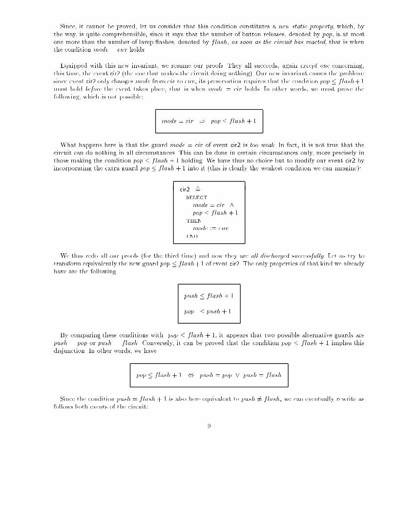
Since, it cannot be proved, let us consider that this condition constitutes a new static property, which, bythe way, is quite comprehensible, since it says that the number of button releases, denoted by pop, is at mostone more than the number of lamp ashes, denoted by flash, as soon as the circuit has reacted, that is whenthe condition mode = env holds.
Equipped with this new invariant, we resume our proofs. They all succeeds, again except one concerning,this time, the event cir2 (the one that makes the circuit doing nothing). Our new invariant causes the problem:since event cir2 only changes mode from cir to env, its preservation requires that the condition pop � flash+1must hold before the event takes place, that is when mode = cir holds. In other words, we must prove thefollowing, which is not possible:
mode = cir ) pop � flash + 1
What happens here is that the guard mode = cir of event cir2 is too weak. In fact, it is not true that thecircuit can do nothing in all circumstances. This can be done in certain circumstances only, more precisely inthose making the condition pop � flash + 1 holding. We have thus no choice but to modify our event cir2 byincorporating the extra guard pop � flash + 1 into it (this is clearly the weakest condition we can imagine):
cir2 b=select
mode = cir ^pop � flash + 1
then
mode := env
end
We thus redo all our proofs (for the third time) and now they are all discharged successfully. Let us try totransform equivalently the new guard pop � flash+1 of event cir2. The only properties of that kind we alreadyhave are the following
push � flash + 1
pop � push+ 1
By comparing these conditions with pop � flash + 1, it appears that two possible alternative guards arepush = pop or push = flash. Conversely, it can be proved that the condition pop � flash + 1 implies thisdisjunction. In other words, we have
pop � flash + 1 , push = pop _ push = flash
Since the condition push = flash + 1 is also here equivalent to push 6= flash, we can eventually rewrite asfollows both events of the circuit:
9

cir1 b=select
mode = cir ^push 6= flash
then
mode := env kflash := flash + 1
end
cir2 b=select
mode = cir ^push = pop _ push = flash
then
mode := env
end
As can be seen, when push 6= flash holds the circuit can either choose (event cir1) to ash the lamp orto postpone the ashing (event cir2), but the latter case is only possible provided push = pop holds, in otherwords when the button is being depressed. As soon as the button is released (when push 6= pop holds) and ifthe ash has not yet happened (when push 6= flash still holds), then the guard of event cir2 becomes false andthe circuit has no choice left (it is not possible to postpone the ashing any longer) except to �re the eventcir1, which indeed ashes the lamp.
To summarize, what we have discovered is that the circuit can ash the lamp at the earliest just after thedepressing of the button by the environmental event env1 (when push 6= flash just holds), or at the latest justafter the release of the button by the environmental event env2 (when pop = push + 1 just holds). Betweenthese two events, the circuit is non-deterministic: again, it can choose either to ash the lamp or to do nothing.The following schemas show these two extreme situations:
+--------------+ +-------------+
| | | |
-----+ +------- -----+ +------
+-+ +-+
| | | |
-----+ +-------------------- -------------------+ +----
Interestingly enough, a situation like the next one, altough correct, is potentially dangerous as the button canbe depressed again at any time as soon as it has been released. notice that his solution has been \naturally"rejected by our design:
+--------------+
| |
-----+ +--------
+-+
| |
-----------------------+ +---
What we have shown with the development of this little example is that the necessity of proving has forcedus to deeply understand the nature of our problem and has led us towards a correct solution: it has shown theconcept of design by proof at work. But, of course, we have not yet a circuit. For the moment, we just have anabstraction of it (as well as one of our environment). The next step is to try to derive one or more deterministiccircuits from our formal speci�cation. But before that, we have to make a little detour through the concept ofre�nement.
10

2.2. Re�ning the Circuit by Diminishing its Non-determinacy
In this section, we shall present a �rst way of re�ning our circuit. This corresponds to removing some (orall) of its possible non-deterministic behaviors.
When a circuit is made of various events whose guards are overlapping (i.e. can hold together), a possiblere�nement consists in having these guards made stronger so that they do not overlap any more, but are stillcovering all situations so that no deadlock is possible (this would happen should all guards of the circuit befalse at the same time). Let us reconsider the two events of our circuit:
cir1 b=select
mode = cir ^push 6= flash
then
mode := env kflash := flash + 1
end
cir2 b=select
mode = cir ^push = pop _ push = flash
then
mode := env
end
The guards, clearly, may overlapp when push 6= flash and push = pop hold simultaneously. We can seeimmediately that there are two di�erent ways of making this system of events deterministic without introducingdeadlock: (1) by replacing the guard of cir2 by push = flash, and (2) by adding the extra guard push 6= pop tothat of the event cir1. The net e�ect, in both cases, is to make each guard the negation of the other. Interestinglyenough, these two solutions also corresponds exactly to the two special cases we have discussed in the previoussection. The �rst solution, which we call PULSER1, corresponds to ashing the lamp as early as possible:
cir1 b=select
mode = cir ^push 6= flash
then
mode := env kflash := flash + 1
end
cir2 b=select
mode = cir ^push = flash
then
mode := env
end
In this case, we have the extra invariant property stating that once the circuit has reacted (i.e. when mode = env
holds) then the number of ashes is always equal to the number of button depressions.
mode = env ) push = flash
The second solution, which we call PULSER2, corresponds to ashing the lamp as late as possible.
11
cir1 b=select
mode = cir ^push 6= pop ^ push 6= flash
then
mode := env kflash := flash + 1
end
cir2 b=select
mode = cir ^push = pop _ push = flash
then
mode := env
end
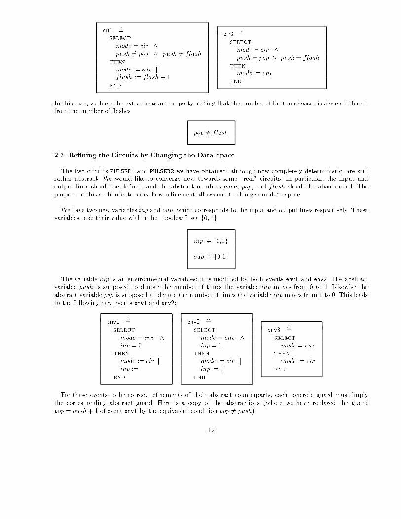
In this case, we have the extra invariant property stating that the number of button releases is always di�erentfrom the number of ashes
pop 6= flash
2.3. Re�ning the Circuits by Changing the Data Space
The two circuits PULSER1 and PULSER2 we have obtained, although now completely deterministic, are stillrather abstract. We would like to converge now towards some \real" circuits. In particular, the input andoutput lines should be de�ned, and the abstract numbers push, pop, and flash should be abandonned. Thepurpose of this section is to show how re�nement allows one to change our data space.
We have two new variables inp and oup, which corresponds to the input and output lines respectively. Thesevariables take their value within the \boolean" set f0; 1g
inp 2 f0,1g
oup 2 f0,1g
The variable inp is an environmental variables: it is modi�ed by both events env1 and env2. The abstractvariable push is supposed to denote the number of times the variable inp moves from 0 to 1. Likewise theabstract variable pop is supposed to denote the number of times the variable inp moves from 1 to 0. This leadsto the following new events env1 and env2:
env1 b=select
mode = env ^inp = 0
then
mode := cir kinp := 1
end
env2 b=select
mode = env ^inp = 1
then
mode := cir kinp := 0
end
env3 b=select
mode = env
then
mode := cir
end
For these events to be correct re�nements of their abstract counterparts, each concrete guard must implythe corresponding abstract guard. Here is a copy of the abstractions (where we have replaced the guardpop = push+ 1 of event env1 by the equivalent condition pop 6= push):
12

env1 b=select
mode = env ^pop 6= push
then
mode := cir kpush := push + 1
end
env2 b=select
mode = env ^pop = push
then
mode := cir kpop := pop+ 1
end
env3 b=select
mode = env
then
mode := cir
end
The correct re�nement thus clearly involves proving the following relationship between the concrete environ-mental space and the abstract one (this proof is straightforward):
inp = 1 , pop = push
Let us now turn to the implementation of the abstract circuit PULSER1. We have the following abstract circuitevents:
cir1 b=select
mode = cir ^push 6= flash
then
mode := env kflash := flash + 1
end
cir2 b=select
mode = cir ^push = flash
then
mode := env
end
The abstract circuit variable flash has to disappear. It counts the number of time the concrete variable oupmoves from 0 to 1. For this, the guard of the concrete event cir1 must check that the abstract variable pushhas just been modi�ed by the environment. As we know, this is when the input line inp moves from 0 to 1.Clearly, we can access the actual value of inp, but certainly not its previous value. We have no choice then butto introduce a register, reg, internal to our circuit, and whose role is to "store" the previous value of inp. Thisleads to the following tentative \implementation" of the events cir1 and cir2
cir1 b=select
mode = cir ^inp = 1 ^ reg = 0
then
mode := env koup := 1 kreg := inp
end
cir2 b=select
mode = cir ^inp = 0 _ reg = 1
then
mode := env koup := 0 kreg := inp
end
The concrete guards must imply the abstract ones.We also clearly have an equality between reg and inp
when mode = env holds. All this leads to the following properties to be maintained (which are both easilyprovable):
13

mode = cir ) ((inp = 1 ^ reg = 0) , push 6= flash)
mode = env ) reg = inp
Finally, for flash to count the number of times oup is made 1, we must prove that when the event cir1 doesoccur (when its guard holds) then oup is 0, that is
mode = cir ^ push 6= flash ) oup = 0
This in turns requires proving the following which is obvious
mode = env ^ inp = 0 ) oup = 0
Our next design step is to depart from the closed system and consider the circuit PULSER1 in isolation. Forthis we just remove from the corresponding events any reference to mode. This leads to the following events:
cir1 b=select
inp = 1 ^ reg = 0then
oup := 1 kreg := inp
end
cir2 b=select
inp = 0 _ reg = 1then
oup := 0 kreg := inp
end
These two events can now be put together as follows in a straightforward fashion:
cir12 b=if inp = 1 ^ reg = 0 then
oup := 1 kreg := inp
else
oup := 0 kreg := inp
end
We have eventually constructed our little circuit PULSER1 (where the \@" symbol indicates complementation):
inp +-----+ +-----+
-->---+---| reg |-->--@ | oup
| +-----+ | AND +--->---
+------------>--+ |
+-----+
14

We could construct the following circuit PULSER2 in a similar fashion
inp +-----+ +-----+
-->---+---| reg |-->--| | oup
| +-----+ | AND +--->---
+------------>--@ |
+-----+
3. A Second Example
Our next example is one where the circuit retro-acts on the environment, which was not the case in theprevious one.
3.1. Informal Speci�cation
This simple circuit is called the (binary) Arbiter. It has two boolean input lines called i1 and i2 and twoboolean output lines called o1 and o2.
+===========+
i1 ! ! o1
----->-----! !----->-----
i2 ! ARBITER ! o2
----->-----! !----->-----
! !
+===========+
Fig. 5. The interface of the arbiter
When ii is valued to 1, this means that a certain useri, associated by construction with the line ii, has required(asked for) the usage of a certain shared resource (the speci�c resource in question as well as the nature of theusers do not play any role in this system). When the circuit, sollicitated with input ii valued to 1, reacts withthe output oi valued to 1, this means that the circuit has indeed granted the resource to useri. Of course anoutput oi can only be valued to 1 when the corresponding input ii is 1. Conversely, the circuit should reactas soon as it can. But this reaction is constrained by the fact that the circuit can only grant the resource toat most one user at a time. Notice that each winning user is supposed to immediately release the resource sothat it can ask for it again immediately after getting it. We have a number of additional constraints:
1. No requiring user can be inde�nitely denied the right to obtain the resource (this could be the case, shouldthe other user always requires the resource again immediately after getting it). Notice that in this example,we shall make this constraint more precise by asking that a requiring user should not wait for more thanone clock pulse before being served. In other words, a new requesting user, if not served at the next circuitreaction, must necessarily be served at the one that follows the next.
2. We suppose that a requiring user shall not give up requiring the resource without being served (this is justa simpli�cation that could have been relaxed).
3. Finally, we require that the circuit correctly reacts to the void case where no user is asking for the resource:in that case, the resource must not then be granted to any user.
15

We do not know whether it is possible to build such a circuit. We do not know either whether such a circuit,supposedly constructed, is free from any deadlock in some situations.
3.2. Formal Static Speci�cation
In the formal speci�cation, we shall abstract from the boolean input and output lines as described in theprevious section. We consider that in the environment, we can count the numbers r1 and r2 of requirementsmade by each user and the corresponding numbers a1 and a2 of acknowledgements made by the circuit. Theconstraint of the informal speci�cation imposes the following straightforward permanent invariant where it isstated that the number of requests is at most one more than the number of acknowledgements:
r1 2 N ^ r2 2 Na1 2 N ^ a2 2 N
a1 � r1 � a1 + 1a2 � r2 � a2 + 1
The \waiting time" of any requiring user is at most equal to 1. This can be formalized by two counters n1and n2 that are incremented as soon that a requesting user is not served and reset in case it has just beenserved:
n1 2 f0; 1g ^ n2 2 f0; 1g
When the mode is cir, we have a situation that has just been established by the environment for the circuit.In this case, one of the waiting time at least should be equal to 0 (otherwise the circuit would have to grantthe resource to both users, which is not allowed). We have thus:
mode = cir ) (n1 = 0 _ n2 = 0 )
Finally, it should be clear that users having a positive waiting time are requiring users, yielding
mode = cir ) (n1 6= 0 ) r1 6= a1 )mode = cir ) (n2 6= 0 ) r2 6= a2 )
When the mode is env, we have a situation that has just been established by the circuit for the environment.The fact that the circuit does something as soon as it can is formalized by saying that one of the requests atleast is satis�ed. In other words the number of requests is equal to the number of acknowledgements for atleast one user. Formally:
mode = env ) ( r1 = a1 _ r2 = a2 )
16
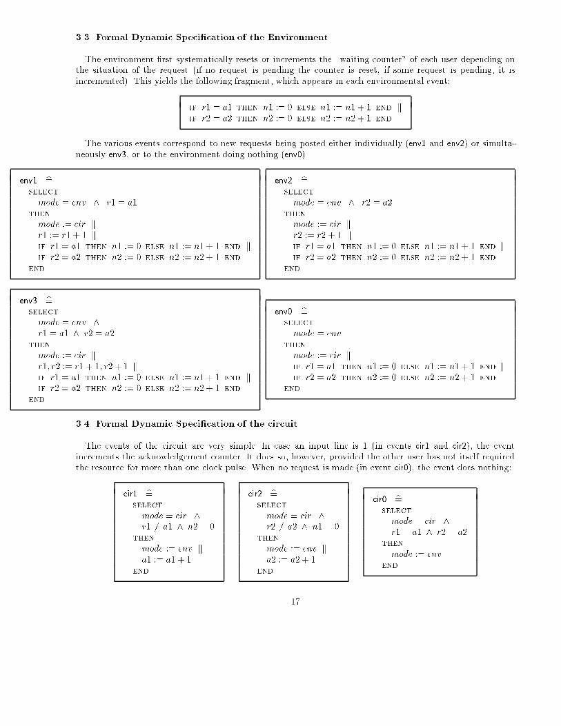
3.3. Formal Dynamic Speci�cation of the Environment
The environment �rst systematically resets or increments the \waiting counter" of each user depending onthe situation of the request (if no request is pending the counter is reset, if some request is pending, it isincremented). This yields the following fragment, which appears in each environmental event:
if r1 = a1 then n1 := 0 else n1 := n1 + 1 end kif r2 = a2 then n2 := 0 else n2 := n2 + 1 end
The various events correspond to new requests being posted either individually (env1 and env2) or simulta-neously env3, or to the environment doing nothing (env0).
env1 b=select
mode = env ^ r1 = a1then
mode := cir kr1 := r1 + 1 kif r1 = a1 then n1 := 0 else n1 := n1 + 1 end kif r2 = a2 then n2 := 0 else n2 := n2 + 1 end
end
env2 b=select
mode = env ^ r2 = a2then
mode := cir kr2 := r2 + 1 kif r1 = a1 then n1 := 0 else n1 := n1 + 1 end kif r2 = a2 then n2 := 0 else n2 := n2 + 1 end
end
env3 b=select
mode = env ^r1 = a1 ^ r2 = a2
then
mode := cir kr1; r2 := r1 + 1; r2 + 1 kif r1 = a1 then n1 := 0 else n1 := n1 + 1 end kif r2 = a2 then n2 := 0 else n2 := n2 + 1 end
end
env0 b=select
mode = env
then
mode := cir kif r1 = a1 then n1 := 0 else n1 := n1 + 1 end kif r2 = a2 then n2 := 0 else n2 := n2 + 1 end
end
3.4. Formal Dynamic Speci�cation of the circuit
The events of the circuit are very simple. In case an input line is 1 (in events cir1 and cir2), the eventincrements the acknowledgement counter. It does so, however, provided the other user has not itself requiredthe resource for more than one clock pulse. When no request is made (in event cir0), the event does nothing:
cir1 b=select
mode = cir ^r1 6= a1 ^ n2 = 0
then
mode := env ka1 := a1 + 1
end
cir2 b=select
mode = cir ^r2 6= a2 ^ n1 = 0
then
mode := env ka2 := a2 + 1
end
cir0 b=select
mode = cir ^r1 = a1 ^ r2 = a2
then
mode := env
end
17
3.5. Proving Consistency and Strengthening the Invariant
When proving the closed system consistency with Atelier B, 72 \proof obligations" (in our jargon, this meansthe statements of the little lemma to be proved) were generated, out of which only 4 (that is 5.5%) where notdischarged by the automatic prover. These are the following (two times each):
mode = env ^ r2 = a2 ^ r1 6= a1 ) n1 + 1 2 f0; 1gmode = env ^ r1 = a1 ^ r2 6= a2 ) n2 + 1 2 f0; 1g
The �rst one has been generated by environmental events env0 and env2 trying to preserve the invariantn1 2 f0; 1g while incrementing n1. The second proof obligation denotes a similar situation with n2, it isgenerated by events env0 and env1. We have the feeling that, in the �rst one, r2 plays no role, and similarlywith r1 in the second one. The consequent n1 + 1 2 f0; 1g could be equivalently replaced by n1 = 0 sincewe already have n1 2 f0; 1g, similarly with n2 + 1 2 f0; 1g. These statements could then be replaced by thefollowing slightly stronger statements:
mode = env ) ( r1 6= a1 ) n1 = 0 )mode = env ) ( r1 6= a2 ) n2 = 0 )
As we have absolutely no way of proving these statements, we have no choice left but to suppose that theyare invariant. In fact these statements are quite intuitive: they say that in the environment a requiring user(r1 6= a1) cannot have its \waiting counter" positive since otherwise this would precisely mean that it is nowwaiting for more than one clock pulse. After incorporating these new invariants and reproving our system,Atelier B generates 81 proof obligations, which are now all discharged automatically.
3.6. Proving Deadlockfreeness
Nothing guarantees, of course, that the circuit events are not stuck because their guards are simultaneouslyfalse. We have thus to prove the following, stating that while in the cir mode, the disjunction of the guards ofthe circuit always hold, (this is easily discharged being just a consequence of the invariant):
mode = cir ) ( r1 6= a1 ^ n2 = 0 ) _ ( r2 6= a2 ^ n1 = 0 ) _ ( r1 = a1 ^ r2 = a2 )
Note however that the circuit is still non-deterministic: this is the case when both users are just requiringthe resource simultaneously (thus n1 = 0 and n2 = 0 hold simultaneously). In this case, both events cir1 andcir2 can be �red.
3.7. Generating Proper Binary 0utputs from the Circuit
In section 3.4, the circuit events cir1 and cir2 incremented directly the acknowledgement counters a1 and a2.These counters both formed the abstract outputs of our circuit. We shall now postpone this incrementation andhave the circuit only generating a 1 or 0 o�set, the proper incrementation itself being done by the environmenton two slightly time-shifted counters, say b1 and b2. This re�nement introduces thus four variables typed asfollows:
18
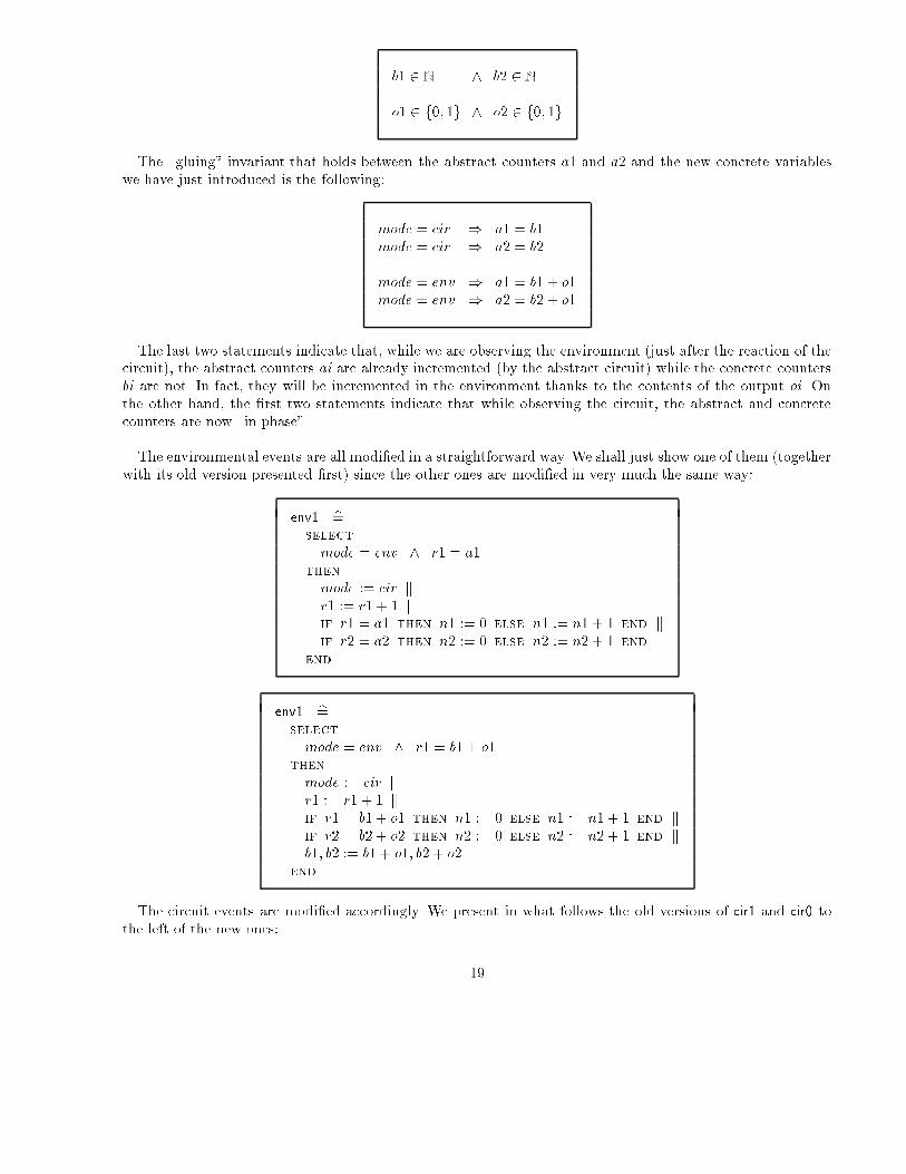
b1 2 N ^ b2 2 N
o1 2 f0; 1g ^ o2 2 f0; 1g
The \gluing" invariant that holds between the abstract counters a1 and a2 and the new concrete variableswe have just introduced is the following:
mode = cir ) a1 = b1mode = cir ) a2 = b2
mode = env ) a1 = b1 + o1mode = env ) a2 = b2 + o1
The last two statements indicate that, while we are observing the environment (just after the reaction of thecircuit), the abstract counters ai are already incremented (by the abstract circuit) while the concrete countersbi are not. In fact, they will be incremented in the environment thanks to the contents of the output oi. Onthe other hand, the �rst two statements indicate that while observing the circuit, the abstract and concretecounters are now \in phase".
The environmental events are all modi�ed in a straightforward way. We shall just show one of them (togetherwith its old version presented �rst) since the other ones are modi�ed in very much the same way:
env1 b=select
mode = env ^ r1 = a1then
mode := cir kr1 := r1 + 1 kif r1 = a1 then n1 := 0 else n1 := n1 + 1 end kif r2 = a2 then n2 := 0 else n2 := n2 + 1 end
end
env1 b=select
mode = env ^ r1 = b1 + o1then
mode := cir kr1 := r1 + 1 kif r1 = b1 + o1 then n1 := 0 else n1 := n1 + 1 end kif r2 = b2 + o2 then n2 := 0 else n2 := n2 + 1 end kb1; b2 := b1 + o1; b2 + o2
end
The circuit events are modi�ed accordingly. We present in what follows the old versions of cir1 and cir0 tothe left of the new ones:
19

cir1 b=select
mode = cir ^r1 6= a1 ^ n2 = 0
then
mode := env ka1 := a1 + 1
end
cir1 b=select
mode = cir ^r1 6= b1 ^ n2 = 0
then
mode := env ko1; o2 := 1; 0
end
cir0 b=select
mode = cir ^r1 = a1 ^ r2 = a2
then
mode := env
end
cir0 b=select
mode = cir ^r1 = b1 ^ r2 = b2
then
mode := env ko1; o2 := 0; 0
end
Atelier B generated 94 proof obligations for proving the correct re�nements, out of which 6 (6.4%) were notdischarged automatically. They were discharged interactively very easily.
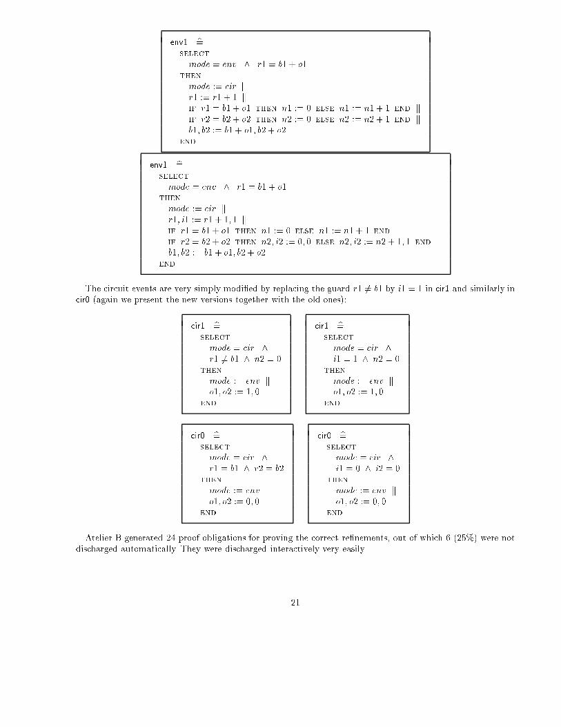
3.7. Generating Proper Binary Inputs from the Environment
The inputs to the circuit, rather than being the number ri of requests and the number bi of acknowledgementscould very well be only their di�erence which is at most 1, as we know. For this, we introduce two new binaryvariables i1 and i2, glued as follows to ri and bi
mode = cir ) r1 = b1 + i1mode = cir ) r2 = b2 + i2
The modi�cation of the environment events are very simple. As for the output in previous section, we shallonly present one such event together with its previous version:
20
env1 b=select
mode = env ^ r1 = b1 + o1then
mode := cir kr1 := r1 + 1 kif r1 = b1 + o1 then n1 := 0 else n1 := n1 + 1 end kif r2 = b2 + o2 then n2 := 0 else n2 := n2 + 1 end kb1; b2 := b1 + o1; b2 + o2
end
env1 b=select
mode = env ^ r1 = b1 + o1then
mode := cir kr1; i1 := r1 + 1; 1 kif r1 = b1 + o1 then n1 := 0 else n1 := n1 + 1 end kif r2 = b2 + o2 then n2; i2 := 0; 0 else n2; i2 := n2 + 1; 1 end kb1; b2 := b1 + o1; b2 + o2
end
The circuit events are very simply modi�ed by replacing the guard r1 6= b1 by i1 = 1 in cir1 and similarly incir0 (again we present the new versions together with the old ones):
cir1 b=select
mode = cir ^r1 6= b1 ^ n2 = 0
then
mode := env ko1; o2 := 1; 0
end
cir1 b=select
mode = cir ^i1 = 1 ^ n2 = 0
then
mode := env ko1; o2 := 1; 0
end
cir0 b=select
mode = cir ^r1 = b1 ^ r2 = b2
then
mode := env ko1; o2 := 0; 0
end
cir0 b=select
mode = cir ^i1 = 0 ^ i2 = 0
then
mode := env ko1; o2 := 0; 0
end
Atelier B generated 24 proof obligations for proving the correct re�nements, out of which 6 (25%) were notdischarged automatically. They were discharged interactively very easily.
21
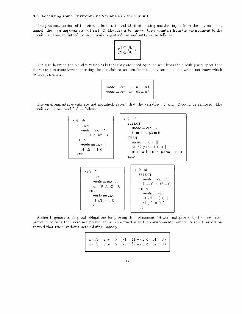
3.8. Localizing some Environment Variables in the Circuit
The previous version of the circuit, besides i1 and i2, is still using another input from the environment,namely the \waiting counters" n1 and n2. The idea is to \move" these counters from the environment to thecircuit. For this, we introduce two circuit \registers", p1 and p2 typed as follows:
p1 2 f0; 1gp2 2 f0; 1g
The glue between the p and n variables is that they are ideed equal as seen from the circuit (we suspect thatthere are also some laws concerning these variables, as seen from the environment, but we do not know whichby now), namely:
made = cir ) p1 = n1made = cir ) p2 = n2
The environmental events are not modi�ed, except that the variables n1 and n2 could be removed. Thecircuit events are modi�ed as follows
cir1 b=select
mode = cir ^i1 = 1 ^ n2 = 0
then
mode := env ko1; o2 := 1; 0
end
cir1 b=select
mode = cir ^i1 = 1 ^ p2 = 0
then
mode := env ko1; o2; p1 := 1; 0; 0 kif i2 = 1 then p2 := 1 end
end
cir0 b=select
mode = cir ^i1 = 0 ^ i2 = 0
then
mode := env ko1; o2 := 0; 0
end
cir0 b=select
mode = cir ^i1 = 0 ^ i2 = 0
then
mode := env ko1; o2 := 0; 0 kp1; p2 := 0; 0
end
Atelier B generates 38 proof obligations for proving this re�nement. 18 were not proved by the automaticprover. The ones that were not proved are all concerned with the environmental events. A rapid inspectionshowed that two invariants were missing, namely:
made = env ) ( r1 = b1 + o1 , p1 = 0 )made = env ) ( r2 = b2 + o1 , p2 = 0 )
22
By reproving our system with this new invariants, Atelier B generated 52 proof obligations, out of whichonly 2 (3.8%) needed an easy interactive proof.
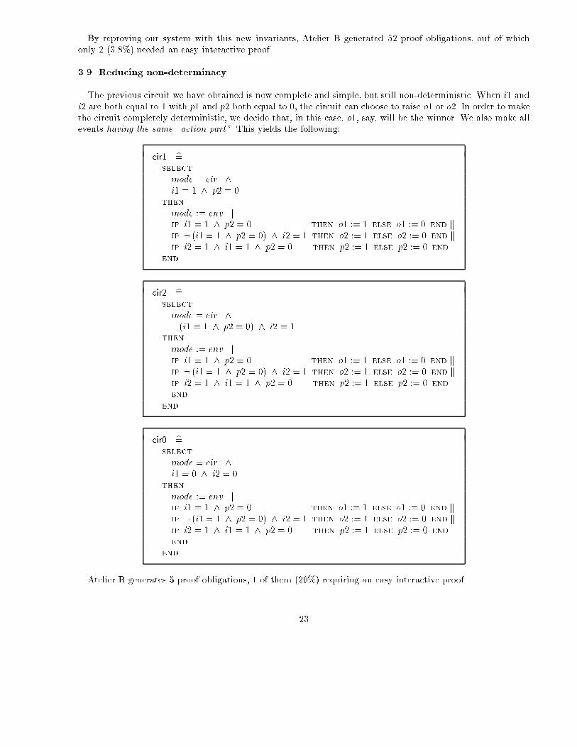
3.9. Reducing non-determinacy
The previous circuit we have obtained is now complete and simple, but still non-deterministic. When i1 andi2 are both equal to 1 with p1 and p2 both equal to 0, the circuit can choose to raise o1 or o2. In order to makethe circuit completely deterministic, we decide that, in this case, o1, say, will be the winner. We also make allevents having the same \action part". This yields the following:
cir1 b=select
mode = cir ^i1 = 1 ^ p2 = 0
then
mode := env kif i1 = 1 ^ p2 = 0 then o1 := 1 else o1 := 0 end kif : (i1 = 1 ^ p2 = 0) ^ i2 = 1 then o2 := 1 else o2 := 0 end kif i2 = 1 ^ i1 = 1 ^ p2 = 0 then p2 := 1 else p2 := 0 end
end
cir2 b=select
mode = cir ^: (i1 = 1 ^ p2 = 0) ^ i2 = 1
then
mode := env kif i1 = 1 ^ p2 = 0 then o1 := 1 else o1 := 0 end kif : (i1 = 1 ^ p2 = 0) ^ i2 = 1 then o2 := 1 else o2 := 0 end kif i2 = 1 ^ i1 = 1 ^ p2 = 0 then p2 := 1 else p2 := 0 end
end
end
cir0 b=select
mode = cir ^i1 = 0 ^ i2 = 0
then
mode := env kif i1 = 1 ^ p2 = 0 then o1 := 1 else o1 := 0 end kif : (i1 = 1 ^ p2 = 0) ^ i2 = 1 then o2 := 1 else o2 := 0 end kif i2 = 1 ^ i1 = 1 ^ p2 = 0 then p2 := 1 else p2 := 0 end
end
end
Atelier B generates 5 proof obligations, 1 of them (20%) requiring an easy interactive proof.
23
3.11. Revisiting Deadlockfreeness
The interesting and fundamental last statement to prove is that the events of the circuit are deadlockfree.For this, we have to prove that, under the hypothesis mode = cir, the disjunction of the guards of the circuitevents are true (the interactive proof of this statement is easy), namely:
mode = cir ) (i1 = 1 ^ p2 = 0) _ (: (i1 = 1 ^ p2 = 0) ^ i2 = 1) _ (i1 = 0 ^ i2 = 0)
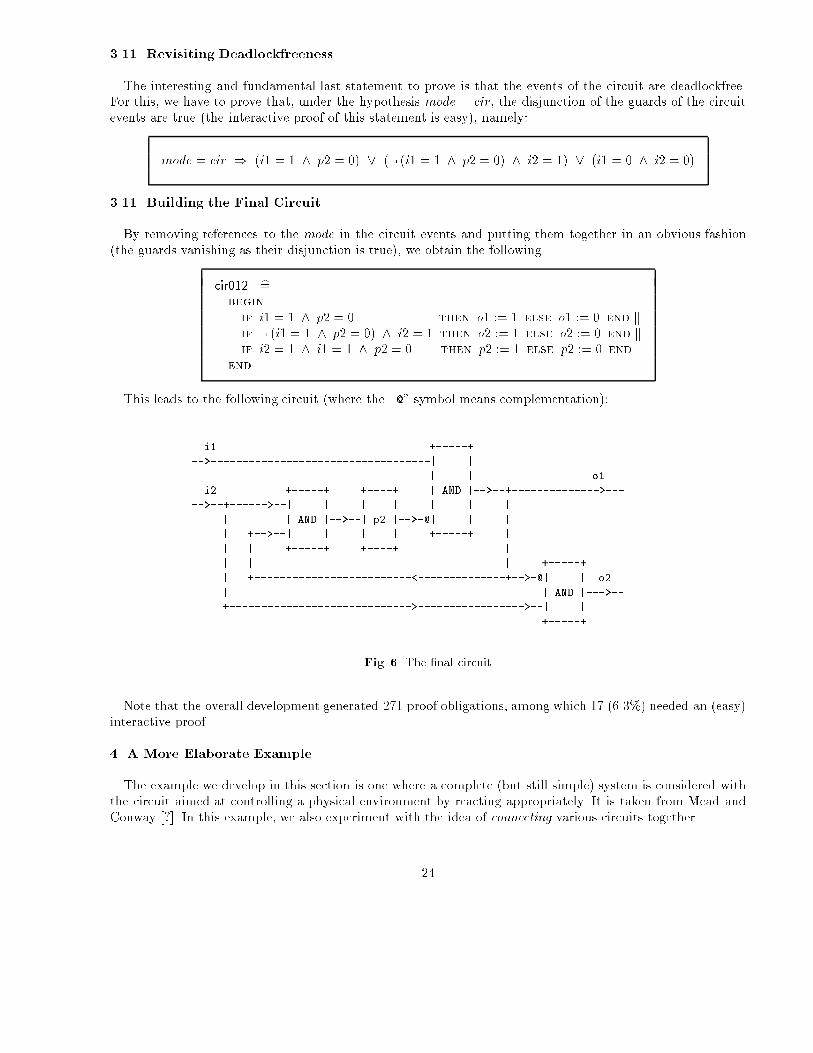
3.11. Building the Final Circuit
By removing references to the mode in the circuit events and putting them together in an obvious fashion(the guards vanishing as their disjunction is true), we obtain the following
cir012 b=begin
if i1 = 1 ^ p2 = 0 then o1 := 1 else o1 := 0 end kif : (i1 = 1 ^ p2 = 0) ^ i2 = 1 then o2 := 1 else o2 := 0 end kif i2 = 1 ^ i1 = 1 ^ p2 = 0 then p2 := 1 else p2 := 0 end
end
This leads to the following circuit (where the \@" symbol means complementation):
i1 +-----+
-->-----------------------------------| |
| | o1
i2 +-----+ +----+ | AND |-->--+-------------->---
-->--+------>--| | | | | | |
| | AND |-->--| p2 |-->-@| | |
| +-->--| | | | +-----+ |
| | +-----+ +----+ |
| | | +-----+
| +-------------------------<--------------+-->-@| | o2
| | AND |--->--
+----------------------------->----------------->--| |
+-----+
Fig. 6. The �nal circuit
Note that the overall development generated 271 proof obligations, among which 17 (6.3%) needed an (easy)interactive proof.
4. A More Elaborate Example
The example we develop in this section is one where a complete (but still simple) system is considered withthe circuit aimed at controlling a physical environment by reacting appropriately. It is taken from Mead andConway [?]. In this example, we also experiment with the idea of connecting various circuits together.
24

4.1 System Speci�cation
One intends to install a tra�c light at the crossing between a main road and a small road. The idea is to havethese lights behaving in such a way that the tra�c on the main road is somehow given a certain advantage overthat on the small road. The corresponding policy is explained (and commented) in the following informallystated rules:
Rule 1 When the light controlling the main road is green, it only turns orange (and subsequently red) when somecars are present on the small road (the presence of such cars is detected by appropriate sensors). As aconsequence, when no cars are present on the small road, the tra�c on the main road is not disturbed.
Rule 2 This potential loss of priority on the main road is however only possible provided that road has already keptthe priority for at least a certain (long) �xed delay. In other words, within that delay, the main road keepsthe priority even if there are cars waiting on the small road. As a consequence, when there are frequentlycoming cars on the small road, the tra�c on the main road is still rather smoothly owing.
Rule 3 On the other hand, the small road, when given priority, keeps it is as long as there are cars willing to crossthe main road.
Rule 4 This keeping of the priority by the small road is however only possible provided a (long) delay (the samedelay as for the main road) has not passed. When the delay is over, the priority systematically returns tothe main road even is there are still some cars present on the small road. As a consequence, when thereis a big amount of cars on the small road, these cars cannot block the main road for too long a period of time.
Rule 5 As already alluded above, a green light does not turn red immediately. An orange color appears as usualfor a (small) amont of time before the light de�nitely turns red. This sequential behavior is the same onthe lights of both roads.
Rule 6 As usual, the safety of the drivers is ensured by the fact that the light, when green or orange on one road, isexactly red on the other one, and vice-versa. Safety is also ensured, of course, provided the drivers obey thelaw of not trespassing a red light (but this is another matter, not under the responsability of the circuit!).
4.2 A Separation of Concern Approach
By reading the previous informal requirements, it appears that there are apparently two separate questionsin this problem: (1) one is dealing with the modi�cation of the priority from the main to the small road andvice-versa (this corresponds to Rule 1 to Rule 4 above), and (2) another one is dealing with the realizationof that change of priority in a way that is meaningful to drivers (this corresponds to Rule 5 and Rule 6): thisconcerns the modi�cation of the colors of each light (from successively, say, green to orange, then to red, andthen to green again, etc), and the obvious non-contradiction between the lights governing each road (no twogreen lights at the same time, etc).
It seems that these two questions are rather \orthogonal" in that a modi�cation in the road priority policyshould not a�ect the proper behaviors of the lights, and vice-versa. Clearly, a modi�cation in the light classicalbehaviour is not something that one would reasonnably envisage as it is rather universal. On the other hand,a modi�cation in the priority policy is a possibility that could not be rejected a priori. In that case, we wouldlike to have the circuit built in such a way that this modi�cation could be done in an easy way (sub-circuitreplacement).
One should also notice that the �rst of these two questions deals with the essential function of this system,namely to alternate the priority between two roads in an unbalanced way. On the other hand, the second
25
question rather deals with the safety and possible progress of the users. In other words, we must ensure thatdrivers: (i) are always in a safe situation provided they obey the usual conventions indicated by the colors ofthe lights, and (ii) are also not blocked inde�nitely (everybody has once experienced a situation where, forinstance, both lights are red!).
Our initial idea is thus to make the design of two distinct circuits, which will be eventually connected. Oneis the Priority circuit, and the other is the Light circuit. The Priority circuit delivers a signal to the Light circuittelling that the priority has to be changed from one road to the other. In this way, the latter can translate this\priority" information in terms of a correponding \tra�c light" information.
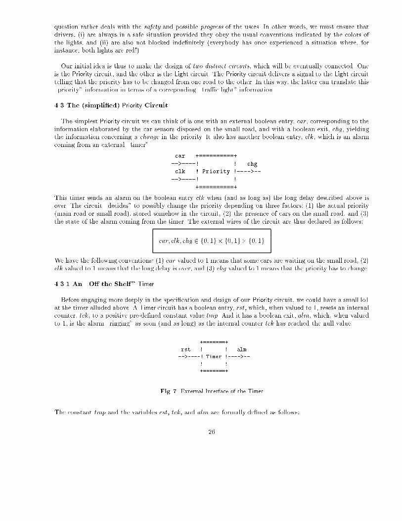
4.3 The (simpli�ed) Priority Circuit
The simplest Priority circuit we can think of is one with an external boolean entry, car, corresponding to theinformation elaborated by the car sensors disposed on the small road, and with a boolean exit, chg, yieldingthe information concerning a change in the priority. It also has another boolean entry, clk, which is an alarmcoming from an external \timer".
car +==========+
-->----! ! chg
clk ! Priority !---->--
-->----! !
+==========+
This timer sends an alarm on the boolean entry clk when (and as long as) the long delay described above isover. The circuit \decides" to possibly change the priority depending on three factors: (1) the actual priority(main road or small road), stored somehow in the circuit, (2) the presence of cars on the small road, and (3)the state of the alarm coming from the timer. The external wires of the circuit are thus declared as follows:
car; clk; chg 2 f0; 1g� f0; 1g� f0; 1g
We have the following conventions: (1) car valued to 1 means that some cars are waiting on the small road, (2)clk valued to 1 means that the long delay is over, and (3) chg valued to 1 means that the priority has to change.
4.3.1 An \O� the Shelf" Timer
Before engaging more deeply in the speci�cation and design of our Priority circuit, we could have a small lo1at the timer alluded above. A Timer circuit has a boolean entry, rst, which, when valued to 1, resets an internalcounter, tck, to a positive pre-de�ned constant value tmp. And it has a boolean exit, alm, which, when valuedto 1, is the alarm \ringing" as soon (and as long) as the internal counter tck has reached the null value.
+=======+
rst ! ! alm
-->----! Timer !---->--
! !
+=======+
Fig. 7. External Interface of the Timer
The constant tmp and the variables rst, tck, and alm are formally de�ned as follows:
26
tmp 2 Ntmp > 0rst 2 f0; 1galm 2 f0; 1gtck 2 0 : : tmpalm = 1 , tck = 0
The last invariant states that alm is exactly set when the counter tck is null. The straightforward events ofTimer are as follows:
timer 1 b=select
rst = 0 ^tck > 1
then
alm := 0 ktck := tck � 1
end
timer 2 b=select
rst = 0 ^tck = 1
then
alm := 1 ktck := tck � 1
end
timer 3 b=select
rst = 0 ^tck = 0
then
alm := 1end
timer 4 b=select
rst = 1then
alm := 0 ktck := tmp
end
As can be seen, when the Timer is not reset (rst = 0), then the counter tck is decremented if positive (in timer 1
and timer 2) until it reaches the value 0 (in timer 2 and timer 3), in which case the exit alm is set to 1. Whenthe Timer is reset (rst = 1), then the counter tck is set to the positive value tmp and alm is reset to 0 (in timer 4).
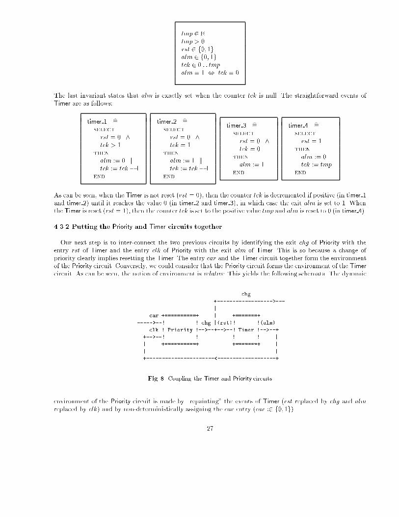
4.3.2 Putting the Priority and Timer circuits together
Our next step is to inter-connect the two previous circuits by identifying the exit chg of Priority with theentry rst of Timer and the entry clk of Priority with the exit alm of Timer. This is so because a change ofpriority clearly implies resetting the Timer. The entry car and the Timer circuit together form the environmentof the Priority circuit. Conversely, we could consider that the Priority circuit forms the environment of the Timer
circuit. As can be seen, the notion of environment is relative. This yields the following schemata. The dynamic
chg
+------------------>---
|
car +==========+ | +=======+
----->--! ! chg |(rst)! !(alm)
clk ! Priority !-->--+-->--! Timer !-->--+
+-->--! ! ! ! |
| +==========+ +=======+ |
| |
+----------------------<-------------------+
Fig. 8. Coupling the Timer and Priority circuits
environment of the Priority circuit is made by \repainting" the events of Timer (rst replaced by chg and alm
replaced by clk) and by non-deterministically assigning the car entry (car :2 f0; 1g).
27

env 1 b=select
mode = env ^chg = 0 ^tck > 1
then
mode := cir kcar :2 f0; 1g kclk := 0 ktck := tck � 1
end
env 2 b=select
mode = env ^chg = 0 ^tck = 1
then
mode := cir kcar :2 f0; 1g kclk := 1 ktck := tck � 1
end
env 3 b=select
mode = env ^chg = 0 ^tck = 0
then
mode := cir kcar :2 f0; 1g kclk := 1
end
env 4 b=select
mode = env ^chg = 1
then
mode := cir kcar :2 f0; 1g kclk := 0 ktck := tmp
end
4.3.3 Specifying the (simpli�ed) Priority Circuit
The Priority circuit has an internal register, prt, holding the actual priority. It is valued 0 (priority on mainroad) or 1 (priority on small road).
prt 2 f0; 1g
The events of the Priority circuit elaborate priority changes. We have three such events, called main to small,small to main 1, and small to main 2. Their guards formally state under which circumstances the priority canchange. This is explained in what follows:
1. Event main to small can be �red when the priority is on main road (prt = 0), when some car are presenton the small road (car = 1) and when the long delay has passed (clk = 1): this corresponds to Rule 1 andRule 2 above.
2. Event small to main 1 can be �red when the priority is on small road (prt = 1), and when no cars arepresent on the small road (car = 0): this corresponds to Rule 3.
3. Event small to main 2 can be �red when the priority is on small road (prt = 1) and when the long delayhas passed (clk = 1): this corresponds to Rule 4.
In all three cases, the priority changes (chg := 1) and prt is modi�ed acccordingly. Here are the events:
main to small b=select
mode = cir ^prt = 0 ^car = 1 ^clk = 1
then
mode := env kprt := 1 kchg := 1 k
end
small to main 1 b=select
mode = cir ^prt = 1 ^car = 0
then
mode := env kprt := 0 kchg := 1
end
small to main 2 b=select
mode = cir ^prt = 1 ^clk = 1
then
mode := env kprt := 0 kchg := 1
end
28
Another series of events corresponds to the circuit doing nothing except resetting the chg exit to 0 (no change).This occurs in three circumstances:
1. Event do nothing 1 can be �red when the priority is on main road (prt = 0) and when there are no cars onthe small road (car = 0): this corresponds to Rule 1 above.
2. Event do nothing 2 can be �red when the priority is on main road (prt = 0) and when the delay has notpassed yet (clk = 0): this corresponds to Rule 2.
3. Event do nothing 3 can be �red when the priority is on small road (prt = 1), when there are cars presenton the small road (car = 1), and when the delay has not passed yet (clk = 0): this corresponds to Rule 3and Rule 4.
Here are these events:
do nothing 1 b=select
mode = cir ^prt = 0 ^car = 0
then
mode := env kchg := 0
end
do nothing 2 b=select
mode = cir ^prt = 0 ^clk = 0
then
mode := env kchg := 0
end
do nothing 3 b=select
mode = cir ^prt = 1 ^car = 1 ^clk = 0
then
mode := env kchg := 0
end
4.3.4 Non-determinacy and Deadlockfreeness
We notice that the priority change events and the \do-nothing" ones do not overlapp, their guards beingclearly disjoint (which is reassuring: the circuit \knows" what it has to do). On the other hand, there isa possible non-determinacy between small to main 1 and small to main 2, and also between do nothing 1 anddo nothing 2. It does not matter however since these couples of events have the same \action" parts.
The circuit does not deadlock as the disjunction of the guards of the various events obviously holds. Hint:observe the guard of main to small versus those of do nothing 1 and do nothing 2, and the guard of do nothing 3
versus those of small to main 1 and small to main 2.
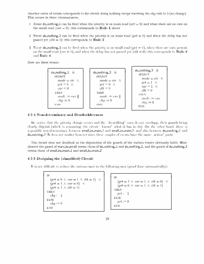
4.3.5 Designing the (simpli�ed) Circuit
It is not di�cult to reduce the various cases to the following ones (proof done automatically):
if
(prt = 0 ^ car = 1 ^ clk = 1) _(prt = 1 ^ car = 0) _(prt = 1 ^ clk = 1)
then
chg := 1else
chg := 0end
if
(prt = 1 ^ car = 1 ^ clk = 0) _(prt = 0 ^ car = 1 ^ clk = 1)
then
prt := 1else
prt := 0end
29

These cases can be further uni�ed as follows (proof done automatically):
if
(car = 1 ^ clk = 1) _(car = 0 ^ prt = 1)
then
chg := 1else
chg := 0end
if
(prt = 1 ^ : ((car = 1 ^ clk = 1) _ (car = 0 ^ prt = 1))) _(prt = 0 ^ ((car = 1 ^ clk = 1) _ (car = 0 ^ prt = 1)))
then
prt := 1else
prt := 0end
In this last version we notice several occurrences of predicates of the form:
(P ^ Q) _ (:P ^ R)
This will be economically represented by an IF Box (for short IFB), considered to be an \atomic" gate. Sucha box is pictorially represented by either one of the following conventions:
P +---+
| Q -->--| I |
| | F |-->--
+-+-+ R -->--| B |
Q -->--| I | +-+-+
| F |-->-- |
R -->--| B | |
+---+ P
Here is the �nal circuit we obtain:
+===================================================+ +------------------->----
car ! ! | chg
----->---------->----+ P r i o r i t y ! |
! | ! |
clk ! +-+-+ ! | +=======+
+-->-------------| I | ! chg |(rst)! !(alm)
| ! prt | F |-->--+------------>-------------------->--+-->--! Timer !-->--+
| ! +-->--| B | | +---+ +---+ ! ! ! |
| ! | +---+ +-->--@ I | | p | prt ! +=======+ |
| ! | | | F |-->--| r |-->--+ ! |
| ! | +-->--| B | | t | | ! |
| ! | +-+-+ +---+ | ! |
| ! | | | ! |
| ! +----------<------------+----------<------+ ! |
| ! ! |
| +===================================================+ |
| |
+-----------------------------------------<-----------------------------------------+
Fig. 9. The �nal simpli�ed circuit
30
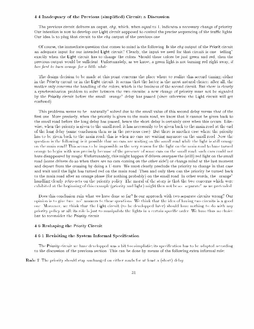
4.4 Inadequacy of the Previous (simpli�ed) Circuit: a Discussion
The previous circuit delivers an ouput, chg, which, when equal to 1, indicates a necessary change of priority.Our intention is now to develop our Light circuit supposed to control the precise sequencing of the tra�c lights.Our idea is to plug that circuit to the chg output of the previous one.
Of course, the immediate question that comes to mind is the following. Is the chg output of the Priorit circuitan adequate input for our intended Light circuit? Clearly, the input we need for that circuit is one \telling"exactly when the Light circuit has to change the colors. Should these colors be just green and red, then theprevious output would be su�cient. Unfortunately, as we know, a green light is not turning red right away, ithas �rst to turn orange for a little while.
The design decision to be made at this point concerns the place where to realize this second timing: eitherin the Priority circuit or in the Light circuit. It seems that the latter is the most natural choice: after all, thematter only concerns the handling of the colors, which is the business of the second circuit. But there is clearlya synchronisation problem to solve between the two circuits: a new change of priority must not be signaledby the Priority circuit before the small \orange" delay has passed (since otherwise the Light circuit will getconfused).
This problems seems to be \naturally" solved due to the small value of this second delay versus that of the�rst one. More precisely, when the priority is given to the main road, we know that it cannot be given back tothe small road before the long delay has passed, hence the short delay is certainly over when this occurs. Like-wise, when the priority is given to the small road, it has necessarily to be given back to the main road at the endof the long delay (same conclusion then as in the previous case). But there is another case where the priorityhas to be given back to the main road: this is when no cars are waiting anymore on the small road. Now thequestion is the following: is it possible that no cars are waiting on the small road while the light is still orangeon the main road? This seems to be impossible as the very reason for the light on the main road to have turnedorange to begin with was precisely because of the presence of some cars on the small road: such cars could nothave disappeared by magic. Unfortunately, this might happen if drivers overpass the (still) red light on the smallroad (some drivers do so when there are no cars coming on the other side!) or change mind at the last momentand depart from the crossing by doing a U-turn. We must clearly preclude the priority to change in that caseand wait until the light has turned red on the main road. Then and only then can the priority be turned backto the main road after an orange phase (for nothing probably) on the small road. In other words, the \orange"handling clearly retro-acts on the priority policy. The moral of the story is that the two concerns which wereexhibited at the beginning of this example (priority and light) might then not be so \separate" as we pretended.
Does this conclusion ruin what we have done so far? Is our approach with two separate circuits wrong? Ouropinion is to give two \no" answers to these questions. We think that the idea of having two circuits is a goodone. Moreover, we think that the Light circuit (to be developped later) should have nothing to do with anypriority policy at all: its role is just to manipulate the lights in a certain speci�c order. We have thus no choicebut to reconsider the Priority circuit.
4.6 Reshaping the Priority Circuit
4.6.1 Revisiting the System Informal Speci�cation
The Priority circuit we have developped was a bit too simplistic: its speci�cation has to be adapted accordingto the discussion of the previous section. This can be done by means of the following extra informal rule:
Rule 7 The priority should stay unchanged on either roads for at least a (short) delay.
31

This delay corresponds to the time during which the light is orange on the side that has just lost the priority.Notice that this rule is only e�ective on the small road since Rule 2 already stipulates that the priority onthe main road should not change before a long delay.
4.6.2 Revisiting the Timer Circuit
In section 4.3.1 we described the speci�cation of a Timer circuit with a simple interface made of an entryrst and an exit alm. The idea is to use that same timer, but with more capabilities. The new timer has twomore exits: one called alm2 and another one called chg2. The exit alm is now called alm1. Here is the newinterface:
+-->-- chg2
|
+=======+
rst -->--! !
! Timer !-->-- alm1
alm2 --<--! !
+=======+
Fig. 10. The new Timer interface
The entry rst resets the timer counter tck to the constant positive value tmp as before. The exit alm1 is setto 1 when the counter tck is null as was alm in the previous timer. The exit alm2 is set to 1 when the countertck is smaller than or equal to the positive constant tmq (supposed to be smaller than and distinct from tmp).When alm2 is set to 1 this means that the short delay is over. Finally, the exit chg2 is set to 1 when the countertck is exactly equal to tmq. The exit chg2 is thus a single pulse telling exactly when the short delay is over:this is clearly a desirable entry for our future circuit Light. This can be formalised as follows:
tmp 2 Ntmq 2 Ntmq < tmp
tmq > 0rst 2 f0; 1galm1 2 f0; 1galm2 2 f0; 1gchg2 2 f0; 1gtck 2 0 : : tmpalm1 = 1 , tck = 0alm2 = 1 , tck � tmq
chg2 = 1 , tck = tmq
The last three invariants state exactly when the exits are set depending on the value of the counter tck. The�rst event is modi�ed as follows:
32

timer 1 b=select
rst = 0 ^tck > 1
then
if tck � tmq + 1 then alm2 := 1 else alm2 := 0 end kif tck = tmq + 1 then chg2 := 1 else chg2 := 0 end ktck := tck � 1
end
As can be seen the exit alm2 and chg2 are set depending on appropriate values of the counter tck. The threeother events are only slightly modi�ed in a straightforward fashion.
timer 2 b=select
rst = 0 ^tck = 1
then
alm1 := 1 kalm2 := 1 kchg2 := 0 ktck := 0
end
timer 3 b=select
rst = 0 ^tck = 0
then
alm1 := 1 kalm2 := 1 kchg2 := 0 k
end
timer 4 b=select
rst = 1then
alm1 := 0 kalm2 := 0 kchg2 := 0 ktck := tmp
end
4.6.3 Revisiting the Interface of the Priority Circuit
The new Priority circuit has the following interface:
+==========+
car -->--! !-->-- chg1
! Priority !
clk1 -->--! !--<-- clk2
+==========+
Fig. 11. The new Priority interface
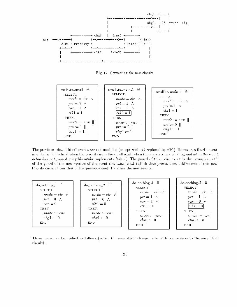
As can be seen, we have changed the name of clk to clk1 and added another entry clk2 that corresponds tothe timer sending an alarm as soon as the short delay is over. Connecting this new circuit with the previousextended Timer yields the conmbined circuits of �gure 11. We now have two exits, namely chg1 and chg2. Theycorrespond to the two possible transitions. We join them with an \OR" gate as indicated, yielding the uniqueexit sig which is now the proper entry for the Light circuit.
4.6.4 Revisiting the Design of the Priority Circuit
The modi�cation in the three priority changing events of the new Priority circuit are rather limited. Wereplace clk by clk1 and chg by chg1, and we extend the guard of event small to main 1 with the predicateclk2 = 1, thus only turning the priority from the small to the main road when there are no cars pending andwhen the small delay is over (this implements Rule 7).
33
chg1 +----+
+----------------------->---| |
| chg2 | OR |-->-- sig
| +---------->---| |
| | +----+
+==========+ chg1 | (rst) +=======+
car --->------! !-->-----+----->--! !(alm1)
clk1 ! Priority ! ! Timer !-->--+
+-->--! !--<-----------<--! ! |
| +==========+ clk2 (alm2) +=======+ |
| |
+----------------------<-------------------------+
Fig. 12. Connecting the new circuits
main to small b=select
mode = cir ^prt = 0 ^car = 1 ^clk1 = 1
then
mode := env kprt := 1 kchg1 := 1 k
end
small to main 1 b=select
mode = cir ^prt = 1 ^car = 0 ^clk2 = 1
then
mode := env kprt := 0 kchg1 := 1
end
small to main 2 b=select
mode = cir ^prt = 1 ^clk1 = 1
then
mode := env kprt := 0 kchg1 := 1
end
The previous \do nothing" events are not modi�ed (except with clk replaced by clk1). However, a fourth eventis added which is �red when the priority is on the small road, when there are no cars pending and when the smalldelay has not passed yet (this again implements Rule 7). The guard of this extra event is the \complement"of the guard of the new version of the event small to main 1 (which thus proves deadlockfreeness of this newPriority circuit from that of the previous one). Here are the new events:
do nothing 1 b=select
mode = cir ^prt = 0 ^car = 0
then
mode := env kchg1 := 0
end
do nothing 2 b=select
mode = cir ^prt = 0 ^clk1 = 0
then
mode := env kchg1 := 0
end
do nothing 3 b=select
mode = cir ^prt = 1 ^car = 1 ^clk1 = 0
then
mode := env kchg1 := 0
end
do nothing 4 b=select
mode = cir ^prt = 1 ^car = 0 ^clk2 = 0
then
mode := env kchg1 := 0
end
These cases can be uni�ed as follows (notice the very slight change only with comparison to the simpli�edcircuit):
34
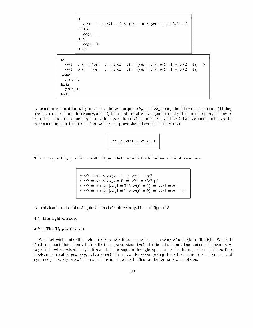
if
(car = 1 ^ clk1 = 1) _ (car = 0 ^ prt = 1 ^ clk2 = 1)then
chg := 1else
chg := 0end
if
(prt = 1 ^ : ((car = 1 ^ clk1 = 1) _ (car = 0 ^ prt = 1 ^ clk2 = 1))) _(prt = 0 ^ ((car = 1 ^ clk1 = 1) _ (car = 0 ^ prt = 1 ^ clk2 = 1)))
then
prt := 1else
prt := 0end
Notice that we must formally prove that the two outputs chg1 and chg2 obey the following properties: (1) theyare never set to 1 simultaneously, and (2) their 1 states alternate systematically. The �rst property is easy toestablish. The second one requires adding two (dummy) counters ctr1 and ctr2 that are incremented as thecorresponding exit turn to 1. Then we have to prove the following extra invariant
ctr2 � ctr1 � ctr2 + 1
The corresponding proof is not di�cult provided one adds the following technical invariants
mode = cir ^ chg2 = 1 ) ctr1 = ctr2mode = cir ^ chg2 = 0 ) ctr1 = ctr2 + 1mode = env ^ (chg1 = 0 ^ chg2 = 1) ) ctr1 = ctr2mode = env ^ (chg1 = 1 _ chg2 = 0) ) ctr1 = ctr2 + 1
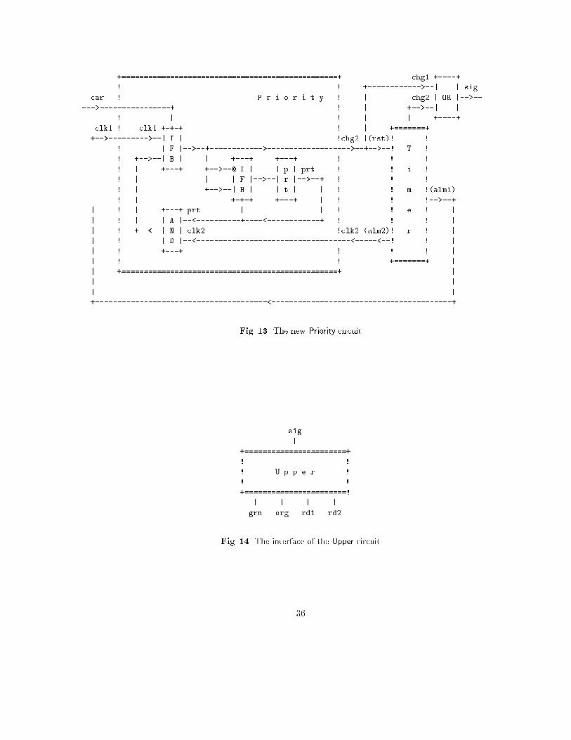
All this leads to the following �nal joined circuit Priority Timer of �gure 13
4.7 The Light Circuit
4.7.1 The Upper Circuit
We start with a simpli�ed circuit whose role is to ensure the sequencing of a single tra�c light. We shallfurther extend that circuit to handle two synchronized tra�c lights. The circuit has a single boolean entrysig which, when valued to 1, indicates that a change in the light appearance should be performed. It has fourboolean exits called grn, org, rd1, and rd2. The reason for decomposing the red color into two colors is one ofsymmetry. Exactly one of them at a time is valued to 1. This can be formalized as follows:
35
+=================================================+ chg1 +----+
! ! +------------>--| | sig
car ! P r i o r i t y ! | chg2 | OR |-->--
--->----------------+ ! | +-->--| |
! | ! | | +----+
clk1 ! clk1 +-+-+ ! | +=======+
+-->--------->--| I | !chg2 |(rst)! !
| ! | F |-->--+------------>------------------->--+-->--! T !
| ! +-->--| B | | +---+ +---+ ! ! !
| ! | +---+ +-->--@ I | | p | prt ! ! i !
| ! | | | F |-->--| r |-->--+ ! ! !
| ! | +-->--| B | | t | | ! ! m !(alm1)
| ! | +-+-+ +---+ | ! ! !-->--+
| ! | +---+ prt | | ! ! e ! |
| ! | | A |--<----------+----<------------+ ! ! ! |
| ! +--<--| N | clk2 !clk2 (alm2)! r ! |
| ! | D |--<-----------------------------------<-----<--! ! |
| ! +---+ ! ! ! |
| ! ! +=======+ |
| +=================================================+ |
| |
| |
+---------------------------------------<-----------------------------------------+
Fig. 13. The new Priority circuit
sig
|
+=======================+
! !
! U p p e r !
! !
+=======================!
| | | |
grn org rd1 rd2
Fig. 14. The interface of the Upper circuit
36
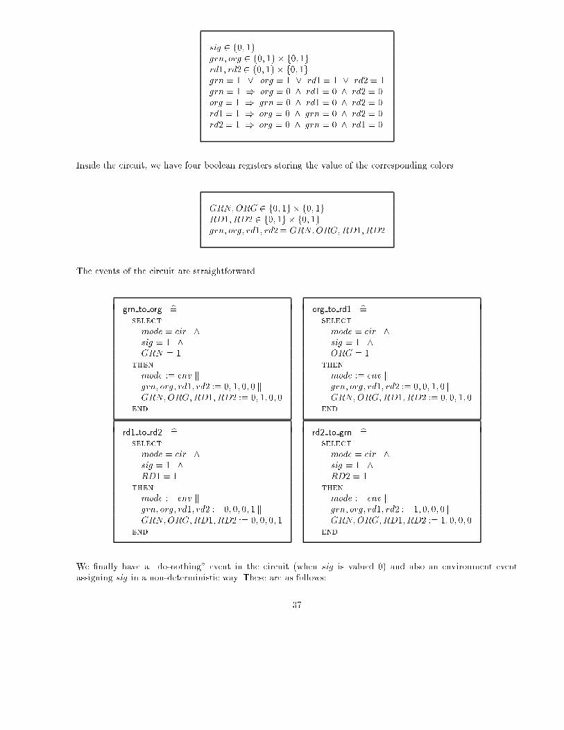
sig 2 f0; 1ggrn; org 2 f0; 1g � f0; 1grd1; rd2 2 f0; 1g � f0; 1ggrn = 1 _ org = 1 _ rd1 = 1 _ rd2 = 1grn = 1 ) org = 0 ^ rd1 = 0 ^ rd2 = 0org = 1 ) grn = 0 ^ rd1 = 0 ^ rd2 = 0rd1 = 1 ) org = 0 ^ grn = 0 ^ rd2 = 0rd2 = 1 ) org = 0 ^ grn = 0 ^ rd1 = 0
Inside the circuit, we have four boolean registers storing the value of the corresponding colors
GRN;ORG 2 f0; 1g � f0; 1gRD1; RD2 2 f0; 1g � f0; 1ggrn; org; rd1; rd2 = GRN;ORG;RD1; RD2
The events of the circuit are straightforward
grn to org b=select
mode = cir ^sig = 1 ^GRN = 1
then
mode := env kgrn; org; rd1; rd2 := 0; 1; 0; 0 kGRN;ORG;RD1; RD2 := 0; 1; 0; 0
end
org to rd1 b=select
mode = cir ^sig = 1 ^ORG = 1
then
mode := env kgrn; org; rd1; rd2 := 0; 0; 1; 0 kGRN;ORG;RD1; RD2 := 0; 0; 1; 0
end
rd1 to rd2 b=select
mode = cir ^sig = 1 ^RD1 = 1
then
mode := env kgrn; org; rd1; rd2 := 0; 0; 0; 1 kGRN;ORG;RD1; RD2 := 0; 0; 0; 1
end
rd2 to grn b=select
mode = cir ^sig = 1 ^RD2 = 1
then
mode := env kgrn; org; rd1; rd2 := 1; 0; 0; 0 kGRN;ORG;RD1; RD2 := 1; 0; 0; 0
end
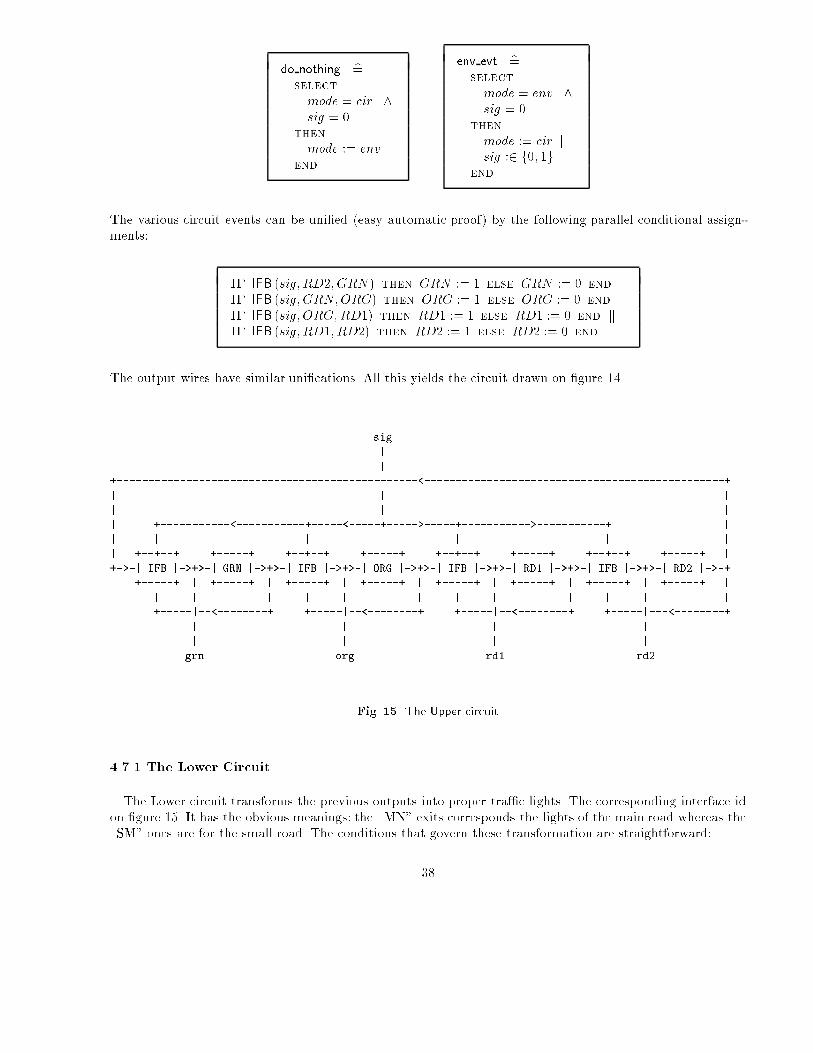
We �nally have a \do-nothing" event in the circuit (when sig is valued 0) and also an environment eventassigning sig in a non-deterministic way. These are as follows:
37
do nothing b=select
mode = cir ^sig = 0
then
mode := env
end
env evt b=select
mode = env ^sig = 0
then
mode := cir ksig :2 f0; 1g
end
The various circuit events can be uni�ed (easy automatic proof) by the following parallel conditional assign-ments:
IF IFB (sig;RD2; GRN ) then GRN := 1 else GRN := 0 end kIF IFB (sig;GRN;ORG) then ORG := 1 else ORG := 0 end kIF IFB (sig;ORG;RD1) then RD1 := 1 else RD1 := 0 end kIF IFB (sig;RD1; RD2) then RD2 := 1 else RD2 := 0 end
The output wires have similar uni�cations. All this yields the circuit drawn on �gure 14.
sig
|
|
+------------------------------------------------<------------------------------------------------+
| | |
| | |
| +-----------<-----------+-----<-----+----->-----+----------->-----------+ |
| | | | | |
| +--+--+ +-----+ +--+--+ +-----+ +--+--+ +-----+ +--+--+ +-----+ |
+->-| IFB |->+>-| GRN |->+>-| IFB |->+>-| ORG |->+>-| IFB |->+>-| RD1 |->+>-| IFB |->+>-| RD2 |->-+
+-----+ | +-----+ | +-----+ | +-----+ | +-----+ | +-----+ | +-----+ | +-----+ |
| | | | | | | | | | | |
+-----|--<--------+ +-----|--<--------+ +-----|--<--------+ +-----|---<--------+
| | | |
| | | |
grn org rd1 rd2
Fig. 15. The Upper circuit
4.7.1 The Lower Circuit
The Lower circuit transforms the previous outputs into proper tra�c lights. The corresponding interface idon �gure 15. It has the obvious meanings: the \MN" exits corresponds the lights of the main road whereas the\SM" ones are for the small road. The conditions that govern these transformation are straightforward:
38

grn org rd1 rd2
| | | |
+=========================================+
! !
! L o w e r !
! !
+=========================================+
| | | | | |
grnMN orgMN redMN grnSM orgSM redSM
Fig. 16. The interface of the Lower circuit
grnMN = grn
orgMN = org
redMN = 1 , ( rd1 = 1 _ rd2 = 1 )grnSM = rd1orgSM = rd2redSM = 1 , ( grn = 1 _ org = 1 )
From these conditions we can deduce the following fundamantal safety conditions stating that when the lightis orange or green on one road it is red on the other and vice-versa (this is Rule 6)
( grnMN = 1 _ orgMN = 1 ) , redSM = 1( grnSM = 1 _ orgSM = 1 ) , redMN = 1
We leave it to the reader to formally construct and prove that the following drawing is indeed a correct con-struction of this circuit: The complete circuit is drawn next page.
grn org rd1 rd2
| | | |
| +-----+ | | +-----+ |
+-->--| O R |--<--+ +-->--| O R |--<--+
| +-----+ | | +-----+ |
| | | | | |
grnMN redSM orgMN grnSM redMN orgSM
Fig. 17. The Lower circuit
5 Conclusion
In this presentation we have shown how the formal construction of little circuits can be realized and mechan-ically proved xwith the B Methods and tools. The technique for connecting circuits that we have considered inthe last example is certainly o,nje that needs more thoughts. But, already as it is, it is certainly the point ofdeparture to envisage the construction of more complex exxamples.
39
Acknowledgements: I would like to thank J. Mermet for very interesting and illuminating discussions andsuggestions.
References
1. J.R. Abrial. The B-Book:Assigning Programs to Meanings. Cambridge University Press (1996).2. J.R. Abrial. Extending B Without Changing it (for Developing Distributed Systems). In H. Habrias, editor, 1st
Conference on the B-Method. November 1996.3. J.R. Abrial and L. Mussat. Introducing Dynamic Constraints in B. In D. Bert editor, B'98: Recent Advances in the
Development and Uses of the B-Method. LNCS vol 1393. 1998.4. T. Kropf. Formal Hardware Veri�cation: Methods and Systems in Comparison. LNCS State-of-the-art Survey
Springer. 1991
40
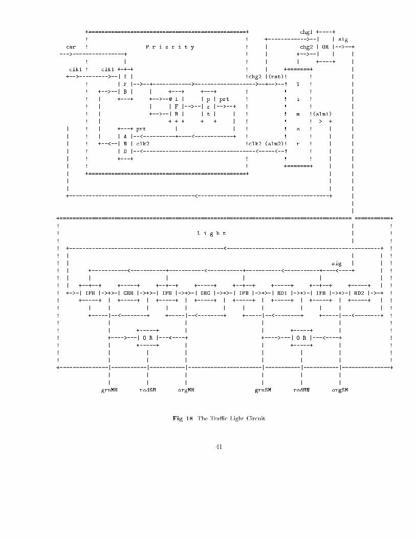
+=================================================+ chg1 +----+
! ! +------------>--| | sig
car ! P r i o r i t y ! | chg2 | OR |-->--+
--->----------------+ ! | +-->--| | |
! | ! | | +----+ |
clk1 ! clk1 +-+-+ ! | +=======+ |
+-->--------->--| I | !chg2 |(rst)! ! |
| ! | F |-->--+------------>------------------->--+-->--! T ! |
| ! +-->--| B | | +---+ +---+ ! ! ! |
| ! | +---+ +-->--@ I | | p | prt ! ! i ! |
| ! | | | F |-->--| r |-->--+ ! ! ! |
| ! | +-->--| B | | t | | ! ! m !(alm1) |
| ! | +-+-+ +---+ | ! ! !-->--+ |
| ! | +---+ prt | | ! ! e ! | |
| ! | | A |--<----------+----<------------+ ! ! ! | |
| ! +--<--| N | clk2 !clk2 (alm2)! r ! | |
| ! | D |--<-----------------------------------<-----<--! ! | |
| ! +---+ ! ! ! | |
| ! ! +=======+ | |
| +=================================================+ | |
| | |
| | |
+---------------------------------------<-----------------------------------------+ |
|
|
+===========================================================================================|===========+
! | !
! L i g h t | !
! | !
! +------------------------------------------------<------------------------------------------------+ !
! | | | !
! | sig | | !
! | +-----------<-----------+-----------<-----------+-----------<-----------+----<----+ | !
! | | | | | | !
! | +--+--+ +-----+ +--+--+ +-----+ +--+--+ +-----+ +--+--+ +-----+ | !
! +->-| IFB |->+>-| GRN |->+>-| IFB |->+>-| ORG |->+>-| IFB |->+>-| RD1 |->+>-| IFB |->+>-| RD2 |->-+ !
! +-----+ | +-----+ | +-----+ | +-----+ | +-----+ | +-----+ | +-----+ | +-----+ | !
! | | | | | | | | | | | | !
! +-----|--<--------+ +-----|--<--------+ +-----|--<--------+ +-----|---<--------+ !
! | | | | !
! | +-----+ | | +-----+ | !
! +---->---| O R |---<----+ +---->---| O R |---<----+ !
! | +-----+ | | +-----+ | !
! | | | | | | !
! | | | | | | !
+===============|===========|===========|=======================|===========|===========|===============+
| | | | | |
| | | | | |
grnMN redSM orgMN grnSM redMN orgSM
Fig. 18. The Tra�c Light Circuit
41