Evaluation Procedure for QoS of Short Message Service
57
Degree project in Communication Systems Second level, 30.0 HEC Stockholm, Sweden NINA MULKIJANYAN International SMS Route Analysis Evaluation Procedure for QoS of Short Message Service KTH Information and Communication Technology
Transcript of Evaluation Procedure for QoS of Short Message Service

Degree project inCommunication Systems
Second level, 30.0 HECStockholm, Sweden
N I N A M U L K I J A N Y A N
International SMS Route Analysis
Evaluation Procedure for QoSof Short Message Service
K T H I n f o r m a t i o n a n d
C o m m u n i c a t i o n T e c h n o l o g y

KTH Royal Institute of Technology
Ascade AB
Evaluation Procedure for QoS of Short MessageService
International SMS Route Analysis
Master’s Thesis
Nina Mulkijanyan
Academic supervisor: Professor Gerald Q. Maguire Jr.Examiner: Professor Gerald Q. Maguire Jr.Industrial supervisor: Martin Jansson
August 17, 2011

Abstract
Due to its ubiquitous availability, Short Message Service (SMS), firstintroduced in the 1980s, became not only the most popular way ofcommunication, but also stimulated the development of SMS-based valueadded services. This application-to-person traffic is delivered to end usersthrough SMS aggregators who provide the link between service providers andmobile carriers. In order to perform optimal traffic routing, the aggregatorsneed to estimate the quality of each potential international route to thespecified destination. The evaluation criteria include end-to-end deliverytime, as well as correct verification of delivered data.
This thesis suggests a method of quality of service (QoS) assessmentfor international SMS service which combines two types of tests, end-to-end delay measurements and various verification tests. A prototype of thetesting system for international SMS service was developed to generate SMStraffic, collect and analyze results, and evaluate the experienced QoS of theSMS route used in accordance with the proposed approach. As a part of end-to-end delay measurement tests, SMS traffic was sent to Singtel network inSingapore along two routes. The verification tests were executed via differentroutes to two mobile networks: Singtel and Tele2 (Sweden). The results ofthe performed measurements determined the route with the highest QoS,i.e. the one with bigger bottleneck bandwidth and lower data loss rate.
The prototype of the SMS testing system can be used by SMSaggregators to verify delivery of a SMS message, check the integrity ofthe message, figure out interconnection type of the route supplier with thedestination carrier and to identify the presence of load balancers in the path.The prototype also makes it possible to compare end-to-end delay times ofseveral routes and compute bottleneck values for each of the tested routes.
Keywords: SMS, QoS, packet-pair, TOPP, end-to-end delay, bottleneckbandwidth, aggregator
ii

Sammanfattning
Tack vare sin utbredda tillganglighet blev Short Message Service (SMS),som introducerades under 1980-talet, inte bara det mest populara sattetatt kommunicera pa, utan stimulerade aven utvecklingen av SMS-baseradetillaggstjanster. Denna applikation-till-person-trafik levereras till slutan-vandarna via SMS-aggregatorer som star for lanken mellan tjansteleveran-torer och mobiloperatorer. For att trafikdirigeringen skall vara sa optimalsom mojlig maste SMS-aggregatorerna uppskatta kvaliten av varje potentiellinternationell rutt till det specificerade slutmalet. Kriterierna som bedomsar bl.a. leveranstiden mellan tva slutpunkter och korrekt verifikation avlevererad data.
Detta examensarbete foreslar en metod for quality of service (QoS)bedomning av internationella SMS tjanster vilken kombinerar tva typer avtester, end-to-end fordrojningsmatningar samt diverse verifieringstester. Enprototyp av testsystemet for internationella SMS tjanster utvecklades for attgenerera SMS trafik, samla in och analysera resultat och for att utvarderaden anvanda SMS ruttens upplevda QoS i enlighet med det foreslagnatillvagagangssattet. Som en del av end-to-end fordrojningsmatningstesternasandes SMS trafik till Singtels nat i Singapore langs tva rutter. Verifiering-stesterna utfordes via olika rutter till tva mobilnatverk: Singtel och Tele2(Sverige). Resultaten av de utforda matningarna faststallde rutten medhogst QoS, d.v.s. rutten med hogre flaskhalsbandbredd och lagre datafrlust.
SMS-testprototypen kan anvandas av SMS-insamlare for att veri-fiera att ett SMS-meddelande levererats, for att kontrollera integritetenhos SMS-meddelandet, for att rakna ut sammankopplingstypen mellanruttleverantoren och destinationsoperatoren och for att avgora ifall detfinns lastbalanserare langs rutten. Prototypen gor det ocksa mojligt attjamfora end-to-end fordrojningstider hos manga rutter och for att beraknaflaskhalsvarden for varje testad rutt.
iii

Acknowledgement
First of all, I would like to express my gratitude to my examiner andacademic supervisor Prof. Gerald Q. Maguire Jr. who is the best supervisorone can dream of. The discussions with Prof. Maguire extended the scope ofthe thesis and motivated me to design additional tests and perform a moredetailed analysis of results.
I am thankful to Ascade AB for giving me an interesting topic andproviding me with the environment to perform international testing. Iwould like to thank Martin Jansson, my industrial supervisor, who has beenextremely supportive throughout my whole stay at Ascade.
I must thank Jing Wu for kindly allowing me to reuse her code aswell for helping me to master the pecularities of Symbian programming. Icannot fail to thank Roy Sutanto who was very helpful during the testingand measurement phase.
I would like to mention Magnuss Ohrman, Mats Ingelstrom andElena Lockhart, whose valuable input helped me to define the industrialrequirements for an SMS testing system.
Last, but not the least, I would like to mention my family, who hasalways stood by my side.
Nina Mulkijanyan
Stockholm, July, 2011
iv

Contents
List of Figures vii
List of Tables viii
Acronyms and Abbreviations ix
1 Introduction 1
1.1 Problem Statement . . . . . . . . . . . . . . . . . . . . . . . . 1
1.2 Goals . . . . . . . . . . . . . . . . . . . . . . . . . . . . . . . 2
1.3 Overview of the Proposed Solution . . . . . . . . . . . . . . . 3
2 Technical Background 4
2.1 SMS Architecture . . . . . . . . . . . . . . . . . . . . . . . . . 4
2.2 SMS Interconnection Models . . . . . . . . . . . . . . . . . . 6
2.3 SMS Protocol . . . . . . . . . . . . . . . . . . . . . . . . . . . 8
2.3.1 Protocol layers . . . . . . . . . . . . . . . . . . . . . . 8
2.3.2 TPDU message format . . . . . . . . . . . . . . . . . . 9
2.3.3 SMS coding scheme . . . . . . . . . . . . . . . . . . . 14
2.3.4 User Data Header . . . . . . . . . . . . . . . . . . . . 14
2.3.5 Concatenated Short Messages . . . . . . . . . . . . . . 14
2.3.6 Application Port Addressing . . . . . . . . . . . . . . 16
2.3.7 SM-RL layer protocol units . . . . . . . . . . . . . . . 16
2.4 SMPP . . . . . . . . . . . . . . . . . . . . . . . . . . . . . . . 17
3 Related Work 19
v

3.1 A reconfigurable QoS monitoring framework for professionalshort message services in GSM networks . . . . . . . . . . . . 20
3.2 A Quantitative Analysis of the Quality of Service of ShortMessage Service in thePhilippines . . . . . . . . . . . . . . . . . . . . . . . . . . . . 21
3.3 Analysis of the Reliability of a Nationwide Short MessageService . . . . . . . . . . . . . . . . . . . . . . . . . . . . . . . 22
3.4 Value Added Services and Content Platforms . . . . . . . . . 22
3.5 Commercial Projects . . . . . . . . . . . . . . . . . . . . . . . 23
4 Methods 24
4.1 Test and Method Description . . . . . . . . . . . . . . . . . . 24
4.1.1 Message Verification . . . . . . . . . . . . . . . . . . . 24
4.1.2 End-to-end Delay Measurement . . . . . . . . . . . . . 25
4.2 Solution Architecture . . . . . . . . . . . . . . . . . . . . . . . 26
5 Results 28
5.1 End-to-end Delay Measurement . . . . . . . . . . . . . . . . . 28
5.1.1 Test Setup . . . . . . . . . . . . . . . . . . . . . . . . 28
5.1.2 Measurement Results for Route 1 to Singtel . . . . . . 29
5.1.3 Measurement Results for Route 2 to Singtel . . . . . . 32
5.1.4 Comparison of Experienced End-to-end Delay forGPRS Channel and Control Channel . . . . . . . . . . 37
5.2 Verification Tests . . . . . . . . . . . . . . . . . . . . . . . . . 37
5.2.1 Sender Address . . . . . . . . . . . . . . . . . . . . . . 37
5.2.2 Alphabet . . . . . . . . . . . . . . . . . . . . . . . . . 38
5.2.3 SMSC Address . . . . . . . . . . . . . . . . . . . . . . 38
5.2.4 SMSC Timestamps . . . . . . . . . . . . . . . . . . . . 40
5.2.5 Concatenated Message . . . . . . . . . . . . . . . . . . 40
6 Conclusions and Future Work 42
6.1 Conclusions . . . . . . . . . . . . . . . . . . . . . . . . . . . . 42
6.2 Future Work . . . . . . . . . . . . . . . . . . . . . . . . . . . 43
vi

List of Figures
2.1 SMS architecture (adapted from [1]) . . . . . . . . . . . . . . 5
2.2 Message transfer [2] . . . . . . . . . . . . . . . . . . . . . . . 5
2.3 SMS-IP integration (adapted from [1]) . . . . . . . . . . . . . 7
2.4 SMS protocol layers [3] . . . . . . . . . . . . . . . . . . . . . 9
3.1 Framework for QoS monitoring[4] . . . . . . . . . . . . . . . 20
4.1 Solution design . . . . . . . . . . . . . . . . . . . . . . . . . . 26
5.1 Singtel, Route 1 . . . . . . . . . . . . . . . . . . . . . . . . . . 31
5.2 Singtel Route 2 . . . . . . . . . . . . . . . . . . . . . . . . . . 33
5.3 Singtel Route 2 via SMSC in Sweden . . . . . . . . . . . . . . 34
5.4 Singtel Route 2, end-to-end delay for all SMS messagesdelivered via SMSC in Sweden . . . . . . . . . . . . . . . . . 36
5.5 GPRS vs GSM . . . . . . . . . . . . . . . . . . . . . . . . . . 38
5.6 Comparison of interconnection models . . . . . . . . . . . . . 39
5.7 Comparison of end-to-end and SMSC delay . . . . . . . . . . 41
vii

List of Tables
2.1 SMS protocols [5] . . . . . . . . . . . . . . . . . . . . . . . . 6
2.2 Peering and hubbing interconnection comparison [6] . . . . . 8
2.3 TPDU types . . . . . . . . . . . . . . . . . . . . . . . . . . . 10
2.4 TPDU parameters [2] . . . . . . . . . . . . . . . . . . . . . . 11
2.5 TP-DCS format . . . . . . . . . . . . . . . . . . . . . . . . . . 14
2.6 Information Element Identifier values [3] . . . . . . . . . . . 15
2.7 IED organization . . . . . . . . . . . . . . . . . . . . . . . . . 16
2.8 Port number range for 16-bit addressing [3] . . . . . . . . . . 16
2.9 RP-MO-DATA type [3] . . . . . . . . . . . . . . . . . . . . . 17
2.10 RP-MT-DATA type [3] . . . . . . . . . . . . . . . . . . . . . . 17
4.1 Tools . . . . . . . . . . . . . . . . . . . . . . . . . . . . . . . . 27
5.1 Initial test setup . . . . . . . . . . . . . . . . . . . . . . . . . 29
5.2 TOPP test setup for Singtel network . . . . . . . . . . . . . . 29
5.3 Observed values for Route 1 to Singtel . . . . . . . . . . . . . 30
5.4 Observed delay values for Route 2 to Singtel for a particular(Swedish) SMSC . . . . . . . . . . . . . . . . . . . . . . . . . 35
5.5 GPRS vs GSM . . . . . . . . . . . . . . . . . . . . . . . . . . 37
5.6 Comparison of interconnection models . . . . . . . . . . . . . 39
viii

Acronyms and Abbreviations
CDMA Code Division Multiple AccessESME External Short Message EntityETSI European Telecommunications Standard InstituteGMSC Gateway MSCGPRS General Packet Radio ServicesGSM Global System for Mobile CommunicationsHLR Home Location RegisterIP Internet ProtocolITU International Telecommunications UnionIWMSC Interworking MSCKPI Key Performance IndicatorMS Mobile StationMSC Mobile Switching CenterMT Mobile TerminatedPDU Protocol Data UnitQoS Quality of ServiceSC Service CenterSLA Service Level AgreementSM MO Short Message Mobile OriginatedSM MT Short Message Mobile TerminatedSME Short Message EntitySMPP Short Message Peer-to-peer ProtocolSMS Short Message ServiceSMS-IP SMS over IPSMSC Short Message Service CenterSS7 Signaling System # 7UCS2 2-byte Universal Character SetVLR Visiting Location Registrar
ix

Chapter 1
Introduction
The chapter introduces the problem of SMS route evaluation, states thegoals of the thesis project, and provides an overview of prototype system tobe developed as a part of this project.
1.1 Problem Statement
Short Message Service (SMS) remains the most popular way of commu-nication even despite the increasing penetration of smartphones and newmessaging services. The main reason for such an active usage of SMS isthat no other messaging service can offer global availability comparable tothat of SMS: as all mobile terminals support SMS, every subscriber of amobile network can be reached via SMS.
According to the International Telecommunication Union (ITU) [7] thetotal number of SMS messages sent worldwide tripled between 2007 and2010. Today roughly two hundred thousand (2 ∗ 105)SMS messages are sentevery second.
One of the reasons for the tremendous growth of SMS traffic is theincreasing number of value added SMS-based services∗, so called premiumservices. Moreover, in order to become a worldwide premium serviceprovider, owning a single Short Message Service Center (SMSC) is not longernecessary; instead the service provider can sign a contract with one or moreSMS gateway providers. These gateway providers can be divided into twocategories: SMS aggregators and Signaling System 7(SS7) providers [8]. Asshould be clear from their name, SS7 providers use SS7 connectivity to routeSMS traffic, while the aggregators have agreements with one or more mobile
∗The examples of value added SMS services are mobile banking, flight check-in, SMSticketing for public transportation, and many more.
1

operators to carry bi-directional SMS traffic. The advantage of SS7 routingis the visibility of the complete SMS path. The aggregators can not controlthe end-to-end delivery of messages because they do not have direct accessto SS7 signaling [8].
The European Telecommunications Standard Institute (ETSI) hasdefined a set of parameters for evaluating the quality provided by an SMSservice [9]:
• SMS Service Non-Accessibility Mobile Originated (MO) [%] is theprobability that the subscriber cannot use the service even thoughthe service is accessible
• SMS Access Delay MO [seconds] is the time between submitting amessage to the SMSC and receiving an acknowledgement from theSMSC
• SMS Completion Failure Ratio [%] is the ratio between the number ofmessages that are not delivered and the total number of SMS messagessent
• SMS End-to-End Delivery Time [seconds] is the time interval betweensubmission of a message and receiving the message at the destination
However, application of these parameters is not always suitable fordescribing and evaluating the quality of service (QoS) for SMS. Usually SMSaggregators need to estimate not only the end-to-end delay of each message,but also verify the integrity of the source address, check if all parts of aconcatenated message were delivered successfully, and verify correct deliveryof a message body (even if it contains special characters). Unfortunately,these other aspects cannot be derived simply from the SMSC’s deliveryreports. Currently no software exists to evaluate these other aspects of SMSservice.
1.2 Goals
The goal of this thesis project is to study the criteria for QoS evaluationof international SMS traffic in terms of each potential route that might beused to carry this traffic, present a conceptual design for a system that coulddo this QoS evaluation, implement a prototype of the system, evaluate thisprototype, and analyze the limitations of this prototype. The prototype willbe used to perform a series of tests. These tests will also be designed as partof this thesis project.
2

1.3 Overview of the Proposed Solution
The proposed system will consist of software and a test SMS messagegenerator connected to an SMS aggregator. This system will send SMSmessages to test nodes along a specified route. The test nodes will consistof representative devices (specifically a Nokia E51 and Nokia E52) capableof sending and receiving SMS messages and executing the software to bedeveloped in this project. The node will extract all the available informationfrom the received test message and forward this information and the receivedmessage to an application server. This application server is responsible forvalidating the information and then reporting the results of the evaluationto the end user using software developed in this thesis project. Therefore,there are two sets of software to be developed: one set for the applicationserver and another for the end devices.
3

Chapter 2
Technical Background
This chapter introduces the technical terms and concepts required tounderstand the work completed in scope of this thesis project. The chaptergives overview of high level SMS architecture and models of interconnectionbetween SMS traffic carriers, and focuses on the technical realization of SMS,as defined by 3GPP.
2.1 SMS Architecture
The Service Center (SC) or Short Message Service Center (SMSC) is oneof the key elements of the overall SMS architecture. A general headset-to-headset view of the SMS architecture is depicted in Figure 2.1. The SMSCacts as relay and store-and-forward entity. The SMSC can be a separatenetwork element or can be integrated into a Mobile Switching Center (MSC)[2].
A short message entity (SME) is a network element capable of sendingand receiving a SMS message. A SME can be connected to the SMSCdirectly or via a gateway; the latter is called an External Short MessageEntity(ESME) [2].
Messages submitted by SME to the SMSC are called Short MessageMobile Originated (SM MO) while messages delivered from the SMSC toSME are referred to as Short Message Mobile Terminated (SM MT).
An SMS message submitted from a Mobile Station (MS) is passed tothe SMSC via an Interworking MSC (IWMSC). The SMSC may send anacknowledgement to the originator, if such an acknowledgement has beenrequested. A gateway MSC (GMSC) is used by the SMSC to route anSMS message to the proper destination network [1]. The GMSC queriesthe Home Location Register (HLR) for routing information and sends the
4

Figure 2.1: SMS architecture (adapted from [1])
SMS message to the serving MSC of the message recipient. The IWMSCand GMSC functionality related to SMS routing can be integrated into theSMSC.
Figure 2.1 does not indicate if the originator and recipient belong to thesame mobile network. Note that this figure is valid when the originator andrecipient are connected to mobile networks utilizing the same technology,i.e., both end points being GSM/GPRS or CDMA, otherwise the issue ofinteroperability is raised. To support messaging between different types ofmobile networks there needs to be a gateway or the corresponding SMSCsneed to be interconnected by a proprietary exchange protocol. [2]
In this context, the delivery of a MT message to a subscriber happensas follows (see Figure 2.2). The originating SME submits the message tothe SMSC of the originating network. The originator’s SMSC forwards themessage to the SMSC of the recipient’s network. Finally the recipient’sSMSC delivers the message to the destination and sends a status reportto the originator’s SMSC (if an acknowledgement was requested). Theoriginator’s SMSC delivers the status report to the message originator (ifacknowledgement was requested). [2]
Figure 2.2: Message transfer [2]
5

However, there is a problem when the originating and terminatingnetworks belong to the same type (CDMA or GSM): when the messageis delivered to the destination by the originator’s SMSC, then the recipientmobile operator has no control over the incoming SMS traffic. To provide therecipient’s SMSC with control, in 2007 the concept of SMS home routing wasadded to the original GSM specification. According to this concept, eachinter-operator SMS message is delivered to the recipient by the receivingoperators SMSC, rather than directly by the originator’s SMSC. This allowsthe receiving operator to analyze all of the incoming SMS messages and blocksome or all of the inbound SMS traffic. [10]
It is also possible to send/receive SMS messages via gateways from/to IPnetworks. This is referred to as SMS-IP. The typical integration of SMS-IPwith SMS is illustrated in Figure 2.3. The ESME connects via an IP channelto a gateway server (e.g. in this case the gateway server belongs to an SMSaggregator). The ESME forwards the inbound SMS-IP traffic to the mobileoperator’s SMSC. The most widely used communication protocols betweenthe SMSC and the gateway are listed in Table 2.1.
Table 2.1: SMS protocols [5]Protocol Owner/Creator
Short Message Peer-to-peer Protocol(SMPP)
SMS Forum/Logica
Universal Computer Protocol (UCP) CMG(now LogicaCMG)
Computer Interface to Message Distribu-tion (CIMD2)
Nokia
Open Interface Specification (OIS) Sema Group (nowSchlumbergerSema)
Telocator Alphanumeric Protocol (TAP) PCIA
2.2 SMS Interconnection Models
Transfer of messages directly between different mobile networks requireslegal agreements and physical interconnections between the operators. Twomodels of interconnection exist: peering and hubbing [11]. A comparison ofthe two interconnectivity models is provided in Table 2.2.
6

Figure 2.3: SMS-IP integration (adapted from [1])
The GSM legacy bilateral (or peering) model of interconnection requireseach network operator to establish direct agreements with each of itspartners [11]. The physical and logical interconnections are each point-to-point.
The hubbing (also known as GSM Open connectivity) model ofinterconnection is based on an agreement between the operator and ahubbing service provider. This agreement allows the operator to route theSMS traffic to a large number of mobile operators without requiring a directagreement with each of them. [6]
The coexistence of the bilateral and hubbing models is based oncategorizing the SMS traffic into person-to-person and application-to-person. The bilateral model makes sense in case of person-to-personcommunication in a country with a high population density while thehubbing model is more suitable for an application-to-person scenario [11].The hubbing model also simplifies international SMS exchange by reducingN ∗ (N − 1)/2 agreements and interconnections between N operators to asingle agreement with a hubbing service provider.
7
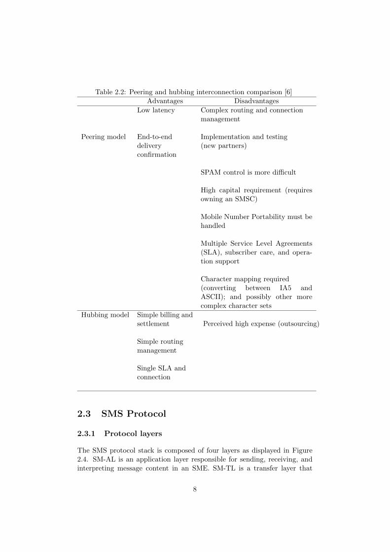
Table 2.2: Peering and hubbing interconnection comparison [6]Advantages Disadvantages
Peering model
Low latency Complex routing and connectionmanagement
End-to-enddeliveryconfirmation
Implementation and testing(new partners)
SPAM control is more difficult
High capital requirement (requiresowning an SMSC)
Mobile Number Portability must behandled
Multiple Service Level Agreements(SLA), subscriber care, and opera-tion support
Character mapping required(converting between IA5 andASCII); and possibly other morecomplex character sets
Hubbing model Simple billing andsettlement Perceived high expense (outsourcing)
Simple routingmanagement
Single SLA andconnection
2.3 SMS Protocol
2.3.1 Protocol layers
The SMS protocol stack is composed of four layers as displayed in Figure2.4. SM-AL is an application layer responsible for sending, receiving, andinterpreting message content in an SME. SM-TL is a transfer layer that
8

provides service to SM-AL [3]. At the SM-TL layer the message is treatedas a Transfer Protocol Data Unit (TPDU) consisting of a number of octetscarrying additional information about the message, such as message length,originator, destination, timestamps, etc. [2]. The SM-RL is a relay layertransporting the TPDU between network elements. The SMS router is anoptional entity used only in the MT case [3]. At the lowest level, SM-LL,provides a link layer that transmits frames over some physical layer.
Figure 2.4: SMS protocol layers [3]
2.3.2 TPDU message format
The types of TPDU at SM-TL layer are listed in table 2.3 [12], while asummary of TPDU parameters is presented in Table 2.4. These messagesare:
• SMS-SUBMIT conveys a short message from the originating SME tothe SMSC.
• An SMS-SUBMIT-REPORT is sent by the SMSC to the originatingSME in order to acknowledge the original message submission; if theSMSC failed to route the message, then the report can be negative.
• The SMS-DELIVER TPDU is sent by the SMSC to deliver a messageto the recipient’s SME.
• An SMS-DELIVER-REPORT is sent by the recipient’s SME to theservice SMSC upon message arrival.
• An SMS-COMMAND is used by originator SME to request commandexecution at the originator SMSC [2]. These commands includedeleting a previously submitted message, requesting the status of apreviously submitted message, cancelling a status report request, etc.
9

• The SMS-STATUS-REPORT delivers the result of a previously sub-mitted SMS-SUBMIT or SMS-COMMAND to the message originator.
Table 2.3: TPDU typesCommand type Direction TP-MTI
SMS-SUBMIT SME -> SMSC 01SMS-SUBMIT-REPORT SMSC -> SME 01SMS-DELIVER SMSC -> SME 00SMS-DELIVER-REPORT SME -> SMSC 00SMS-COMMAND SME -> SMSC 10SMS-STATUS-REPORT SMSC -> SME 10
10

Tab
le2.
4:T
PD
Up
aram
eter
s[2
]
Ab
br
Siz
eR
efer
ence
SU
BM
ITS
UB
MIT
-R
EP
OR
TD
EL
IVE
RD
EL
IVE
R-
RE
PO
RT
ST
AT
US
-R
EP
OR
TC
OM
MA
ND
TP
-CD
1oct
etT
P-C
omm
and
-D
ata
No
No
No
No
No
opt
TP
-CD
L1
oct
etT
P-C
omm
and
-D
ata-L
engt
hN
oN
oN
oN
oN
om
an
TP
-CT
1oct
etT
P-C
om
man
d-
Typ
eN
oN
oN
oN
oN
oM
an
TP
-DA
2-12
oct
ets
TP
-Des
tin
atio
n-
Ad
dre
ssM
anN
oN
oN
oN
oN
o
TP
-DC
ST
P-D
ata-C
od
ing-
Sch
eme
Man
opt
man
op
top
tN
o
TP
-DT
7oct
ets
TP
-Dis
charg
e-T
ime
No
No
No
No
Man
No
TP
-FC
S1
oct
etT
P-F
ail
ure
-Cau
seN
oM
anN
oM
anN
oN
oT
P-M
MS
1b
itT
P-M
ore-
Mes
sage
s-to
-Sen
dN
oN
oM
anM
an
No
No
TP
-MN
1oct
etT
P-M
esage
-N
um
ber
No
No
No
No
No
Man
TP
-MR
1oct
etT
P-M
essa
ge-
Ref
eren
ceM
anN
oN
oN
oN
oM
an
TP
-MT
I2
bit
sT
P-M
essa
ge-
Typ
e-In
dic
ator
Man
Man
Man
Man
Man
Man
11

Ab
br
Siz
eR
efer
ence
SU
BM
ITS
UB
MIT
-R
EP
OR
TD
EL
IVE
RD
EL
IVE
R-
RE
PO
RT
ST
AT
US
-R
EP
OR
TC
OM
MA
ND
TP
-OA
2-1
2oct
ets
TP
-Ori
gin
atin
g-A
dd
ress
No
No
Man
No
No
No
TP
-PI
1oct
etT
P-P
aram
eter
-In
dic
ator
No
Man
No
Man
Opt
No
TP
-PID
1oct
etT
P-P
roto
col-
Iden
tifi
erM
anM
anM
anO
pt
Op
tM
an
TP
-RA
2-1
2oct
ets
TP
-Rec
ipie
nt-
Ad
dre
ssN
oN
oN
oN
oM
an
No
TP
-RD
1b
itT
P-R
ejec
t-D
up
lica
tes
Man
No
No
No
No
No
TP
-RP
1bit
TP
-Rep
ly-P
ath
No
Man
No
No
No
No
TP
-SC
TS
7oct
ets
TP
-Ser
vic
e-C
ente
r-T
ime-
Sta
mp
Man
Man
No
No
No
No
TP
-SR
I1
bit
TP
-Sta
tus-
Rep
ost-
Ind
icat
ion
No
No
Op
tN
oN
oN
o
TP
-SR
Q1
bit
TP
-Sta
tus-
Rep
ort-
Qu
alifi
erN
oN
oN
oN
oM
an
No
TP
-SR
R1
bit
TP
-Sta
tus-
Rep
ort-
Req
ues
tO
pt
No
No
No
No
No
TP
-ST
1oct
etT
P-S
tatu
sN
oN
oN
oN
oM
an
No
TP
-UD
vari
able
TP
-Use
r-D
ata
Op
tO
pt
Opt
Op
tO
pt
No
12

Ab
br
Siz
eR
efer
ence
SU
BM
ITS
UB
MIT
-R
EP
OR
TD
EL
IVE
RD
EL
IVE
R-
RE
PO
RT
ST
AT
US
-R
EP
OR
TC
OM
MA
ND
TP
-UD
HI
1b
itT
P-U
ser-
Dat
a-H
ead
er-I
nd
icat
orO
pt
Op
tO
pt
Op
tO
pt
Op
t
TP
-UD
L1
oct
etT
P-U
ser-
Dat
a-L
ength
Man
Op
tM
anO
pt
Op
tN
o
TP
-VP
1oct
etor
7oct
ets
TP
-Val
idit
y-
Per
iod
opt
No
No
No
No
No
TP
-VP
F2
bit
sT
P-V
ali
dit
y-
Per
iod
-Form
atM
anN
oN
oN
oN
oN
o
13

2.3.3 SMS coding scheme
The message can be encoded using one of the several alphabets: GSM7-bit default alphabet (value 00), 8-bit data (01), or UCS2 (10) [13]. As themaximum SMS message size is 140 bytes, the number of characters dependson the coding scheme used: the message can contain up to 160 charactersusing the GSM 7-bit coding scheme, 140 octets of 8-bit data, or 70 unicodecharacters in the case of UCS2. The coding scheme value used is specified bythe TP-DCS parameter (see Table 2.5). For general data coding bits 7-4 are00xx. The message class can take the following values: mobile equipmentspecific (01), SIM specific (10), or terminal specific (11) use [13]. Messageclass 00 stands for immediate display also known as ”flash SMS”.
Table 2.5: TP-DCS formatbit 7 6 5 4 3 2 1 0
meaning coding group coding schema message class
2.3.4 User Data Header
User Data Header (UDH) Indicator (TP-UDHI) is a 1 bit field in the firstoctet of the PDUs listed in Figure 2.3 [3]. If the bit is set to 1, it means thatthe User Data (TP-UD) field contains the header followed by the messagebody. The header consists of a length field and one or more informationelements. Each information element includes an identifier, element length,and data.
The possible utilization of UDH together with corresponding identifiersare listed in Table 2.6.
2.3.5 Concatenated Short Messages
The maximum size of a SMS message is 140 bytes, but as described inSection 2.3.3 the number of characters in a textual short message dependson the encoding. A long message is transferred across the mobile networkas several messages which are reassembled at the end device transparentlyto the message recipient. Table 2.7 illustrates the octet alignment of theinformation element data.
14
Table 2.6: Information Element Identifier values [3]Value (hex) Meaning
00 Concatenated short messages, 8-bit reference number01 Special SMS Message Indication04 Application port addressing scheme, 8 bit address05 Application port addressing scheme, 16 bit address06 SMSC Control Parameters07 UDH Source Indicator08 Concatenated short message, 16-bit reference number09 Wireless Control Message Protocol0A Text Formatting0B Predefined Sound0C User Defined Sound (iMelody max 128 bytes)0D Predefined Animation0E Large Animation (16*16 times 4 = 32*4 =128 bytes)0F Small Animation (8*8 times 4 = 8*4 =32 bytes)10 Large Picture (32*32 = 128 bytes)11 Small Picture (16*16 = 32 bytes)12 Variable Picture13 User prompt indicator14 Extended Object15 Reused Extended Object16 Compression Control17 Object Distribution Indicator18 Standard WVG object19 Character Size WVG object1A Extended Object Data Request Command1B-1F Reserved for future EMS features (see subclause 3.10)20 RFC 822 E-Mail Header21 Hyperlink format element22 Reply Address Element23 Enhanced Voice Mail Information24 National Language Single Shift25 National Language Locking Shift26 6F Reserved for future use70 7F (U)SIM Toolkit Security Headers80 9F SME to SME specific useC0 DF SC specific use
15

Table 2.7: IED organizationOctet Meaning Value range
1 Concatenated short message reference a modulo 2562 Total number of short messages in the
concatenated message0-255
3 Sequence number of the current shortmessage
0-255
2.3.6 Application Port Addressing
A short message can be routed to one of several applications running on MSby specifying an SMS application port number, similar to TCP/UDP ports.The length of the port number information element is two octets and fouroctets in case of 8 bit and 16 bit addressing respectively. The first octet (thefirst two octets) carries the destination port number while the following (orfollowing two) contains the originator’s port number [3].
For 8-bit addressing the valid port number range is 240-255. The rangefor 16-bit port numbers is shown in Table 2.8.
If port number addressing is applied to a concatenated message, thecorresponding information element must be included in each of the shortmessages composing the concatenated message [3].
Table 2.8: Port number range for 16-bit addressing [3]From To Meaning
0 15999 UDP/TCP port numbers assigned by IANAwithout the need to refer to 3GPP
16000 16999 Available for use without the need to refer to3GPP or IANA
17000 49151 UDP/TCP port numbers assigned by IANA49152 65535 Reserved for future allocation by 3GPP
2.3.7 SM-RL layer protocol units
The service provided by the SM-RL layer to the SM-TL layer allows thetransport layer to exchange TPDUs with its peer entities. These TPDUsare carried inside RP-MO-DATA and RP-MT-DATA elements of MS toSMSC and SMSC to MS paths respectively. [3] The format of RP-MO-DATA and RP-MT-DATA protocol units are shown in Table 2.9 and Table2.10 respectively.
16

Table 2.9: RP-MO-DATA type [3]Abbr. Reference Description
RP-OA RP-Originating-Address Address of the originating MSRP-DA RP Destination Address Address of the destination SMSCRP-UD RP User Data Parameter containing the TPDU
Table 2.10: RP-MT-DATA type [3]Abbr. Reference Description
RP-PRI RP Priority Request Indicates whether or not the shortmessage transfer should be stoppedif the originator SMSC address isalready contained in the MWD
RP-MMS RP More Messages To Send Indicates that there are more mes-sages waiting in the SMSC
RP-OA RP-Originating-Address Address of the originating SMSCRP-DA RP Destination Address Address of the destination MSRP-UD RP User Data Parameter containing the TPDURP-MTI RP-Message Type Indicator Indicates if the TPDU is a SMS
Deliver or a SMS Status ReportRP-SMEA RP-originating SME-Address Address of the originating SME
2.4 SMPP
Short Message Peer-to-peer Protocol (SMPP) is an industry standardprotocol for communication between SMSC and SMS application system[14]. SMPP supports an exchange of request and response PDUs withina session between the ESME and the SMSC [14]. The ESME originatedsession can be registered as a Transmitter(TX), a Receiver(RX), or aTransceiver(TRX). A transmitter session allows the ESME to submit MTmessages to the SMSC for further delivery to the MS, while a receiver sessionis used to receive messages from the SMSC [15]. A transceiver sessioncombines the functionality of the previous two session types, thus supportingboth MT and MO messaging.
All SMPP operations can be grouped into one of several categories:
• Session Management
• Message Submission
• Message Delivery
• Message Broadcast
• Ancillary Operations
17

The SMPP PDU submit sm is used to submit a message to the SMSCand is the analogue of SMS-SUBMIT TPDU, while deliver sm is similarto SMS-DELIVER TPDU. However, both message submission and messagedelivery can be completed with the PDU data sm.
18
Chapter 3
Related Work
The chapter covers recent work on SMS QoS evaluation. However, most ofthe previous works have focused on the problem of packet loss, reliabilityestimation, and end-to-end latency measurement in normal and overloadoperating conditions. To the author’s knowledge there is no scientificresearch similar to that proposed in this thesis.
The works described below are indirectly related to this thesis project,but they refer to QoS aspects other than the ones presented by this work.None of them mentions the deployment of an SMS gateway. Additionallyall of these works were based on observations on national rather thaninternational level.
The research presented by Canlas, et al. [16] is of interest in the contextof the current project as it provides measurement results for end-to-end delayand delivery loss ratio. Their paper does not examine the reasons for packetloss. However, Waadt, et al. [4] focus on message loss caused by a particularsituation.
The reliability analysis presented in [17] considers the bulk SMS serviceas a considerable source of traffic affecting the overall reliability of SMSservice.
As the prototype implemented within this thesis project will be laterdeveloped for industry use, it was interesting to perform some marketresearch to investigate the existence and type of commercial QoS analysissoftware. The results of this market research is given in Section 4.1.1.
19
3.1 A reconfigurable QoS monitoring frameworkfor professional short message services in GSMnetworks
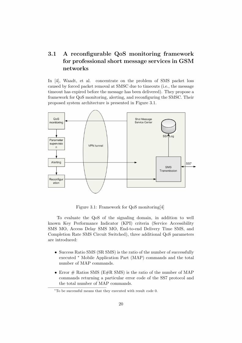
In [4], Waadt, et al. concentrate on the problem of SMS packet losscaused by forced packet removal at SMSC due to timeouts (i.e., the messagetimeout has expired before the message has been delivered). They propose aframework for QoS monitoring, alerting, and reconfiguring the SMSC. Theirproposed system architecture is presented in Figure 3.1.
Figure 3.1: Framework for QoS monitoring[4]
To evaluate the QoS of the signaling domain, in addition to wellknown Key Performance Indicator (KPI) criteria (Service AccessibilitySMS MO, Access Delay SMS MO, End-to-end Delivery Time SMS, andCompletion Rate SMS Circuit Switched), three additional QoS parametersare introduced:
• Success Ratio SMS (SR SMS) is the ratio of the number of successfullyexecuted ∗ Mobile Application Part (MAP) commands and the totalnumber of MAP commands.
• Error # Ratios SMS (E#R SMS) is the ratio of the number of MAPcommands returning a particular error code of the SS7 protocol andthe total number of MAP commands.
∗To be successful means that they executed with result code 0.
20

• Effort SMS (E SMS) is the average number of protocol commandsmade when attempting to transmit a short message.
The QoS parameters values are measured and compared to the valuesstored in a Parameter Supervision block. If the observed values are outof range, then an alert is sent to the SMSC. The system allows automaticreconfiguration of some SMSC parameters such as an SMS retry scheme orthe designated serving MSC.
3.2 A Quantitative Analysis of the Quality ofService of Short Message Service in thePhilippines
Canlas, et al. [16] measured the packet-loss, end-to-end delay, andinaccurate prepaid load† in order to formulate an enhanced QoS equationdescribing the network behaviour, billing performance, and overall servicequality of an SMS system.
Three mobile operators were chosen to create nine sending combina-tions. The following parameters were monitored during the tests: Numberof Messages Received, Number of Messages Sent, Time Delay per message,and Load Consumption. Their final equation for the QoS of SMS is thefollowing [16]:
QoS = ( MRMS,ideal
)3 ∗ (MS,actual
MS,ideal) ∗ ( TI
TD) ∗ (
1.00 Php2
messages2
LC)
where:
QoS = overall QoS [unitless]
MR = number of received message [messages]
MS,ideal = number of messages attempted to be sent [messages]
MS,actual = actual number of messages sent [messages]
TI = Timeliness Index [seconds]
TD = average time delay [seconds]
LC = load consumption
†By inaccurate prepaid billing the authors mean the scenario when the user with aprepaid SMS subscription is charged an amount not equivalent to correct charge for theprovided QoS despite the fact that the charge occurred before the service was actuallyused.
21

3.3 Analysis of the Reliability of a NationwideShort Message Service
Meng, et al. [17] studied SMS reliability based on traces from a nationalcellular operator captured during a three-week period in 2005. The datacontains information about 59 million messages. The message deliveryfailure ratio and end-to-end latency are considered to be the KPIs for servicereliability. According to their research the delivery failure ratio is as highas 5.1%, while the latency experienced by 91% of subscribers is less then5 minutes. However, the same latency value is valid for only 50% of usersduring a ‘flash-crowd‘‡ event.
The authors indicate two factors having a crucial effect on the overallreliability of an SMS service: bulk message delivery and social networks ofSMS users. Notably the ratio between the peak traffic rate and averagerate for the nine content providers that they considered, varies from 9.4 to53.7. All of these ratios are significantly higher than the 3.7 ratio for theperson-to-person traffic.
The collected data were used to build a graph representing the socialnetwork topology formed by SMS subscribers. Their investigation of thetopology influence on the propagation speed of a virus spread by SMS showedthat the speed does not depend on the choice of the first infected node.
3.4 Value Added Services and Content Platforms
One of the goals of Adrian Mahdavi’s master’s thesis project [18] was tocreate an SMS Load Generator and Data Collector in order to evaluate theperformance of an SMSC in two scenarios:
• sending messages at peak rate (10 SMS/s) during 10 minutes
• sending messages at 70% of peak rate during 120 minutes
The first scenario simulates the subscriber activity during a TV show orquiz show, while the latter illustrates the traffic pattern in the hours beforeand after Christmas and New Year.
For both cases a series of tests with increasing duration were performed,viz. the observations were made during 10, 20, 30, and 40 minute intervalsfor the first scenario and during 60, 120, and 180 minute intervals for thesecond. The results showed that the SMSC was able to process the trafficat the peak rate without losses for a maximum of 30 minutes. Another test,
‡A stressful condition caused by coordinated action of a large number of people. Thiskind of situation occurred on New Year’s Eve in 2005.
22

based on generating and sending 11 SMS/s (110% of the 10 SMS/s rate)during a 30 minute period, worked for the 10 SMS/s rate, but this higherload caused the SMSC to crash.
Mahdavi’s tests [18] showed that the SMSC was capable of processingthe traffic at 70% of the peak rate. No packet losses were observed duringthe 60 and 120 minute tests, but during the 180 minute test, 24%(18412out of 75600) of messages were lost and 0.25% were discarded at the SMSC.However, the SMSC was stable and did not crash as it did with a load of 11SMS/s.
Mahdavi also provides separate results of performance testing for theexternal interface and store-and-forward engine’s performance.
3.5 Commercial Projects
Commercial products Xplorer SMS Service [19] and SMS Network Solution[20] developed by Ibys Technologies and Tekelec respectively, allow theoperator to monitor and evaluate the QoS of an SMS service. Theservices provided by Ibys Technologies’ Xplorer SMS Service include messagedelivery and transmission time measurement, failure notification, validationof SMS message content and evaluation of SMS service availability. Tekelec’sSMS Network Solution [20] is focused more on providing an infrastructuresolution for resource allocation for different services, throttling low-prioritytraffic, and providing bandwidth to the higher-priority applications like bulkmessaging.
23

Chapter 4
Methods
This chapter presents the proposed approach for qualitative evaluationof an international SMS traffic route. The chapter introduces the testand measurement methodology, and provides a high level overview of theprototype system used to perform these measurements.
4.1 Test and Method Description
This thesis project will focus on two aspects of QoS evaluation of interna-tional SMS traffic:
1. Verification that the SMS route supplier and destination operatorsupport all the standard SMS parameters and no data was modifiedduring the transmission; and
2. Measurement of end-to-end delay of SMS message delivery.
4.1.1 Message Verification
Message verification tests are used to determine if the test message has beendelivered correctly and to verify the integrity of the received message. Theoriginal message may be modified if the some features are not supportedeither by the transit carrier or by the terminating mobile operator. Thefollowing parameters will be observed via this test framework:
• Sender address - this quite obvious test is necessitated by the fact thatsome suppliers may block traffic from a given alphanumeric originator
• Alphabet - this test verifies that the destination and transit operatorssupport the current encoding and do not reset the encoding to thedefault one. The 8-bit alphabet is also used to identify if the operatorsblock externally originated binary traffic.
24

• SMSC address - the motivation to compare the delivering SMSCs fordifferent routes is to determine what kinds of interconnections are usedby the route suppliers for a given destination network. The output ofthis test for several supplier routes can be analyzed and compared withthe result of the end-to-end delay test set to investigate the degree ofcorrelation between interconnectivity model and the delivery time
• SMSC timestamp - comparison of SMSC timestamp with actualdelivery time at the node
• Concatenated message - verification of correct delivery of a multipartSMS message to the recipient
4.1.2 End-to-end Delay Measurement
The purpose of this test set is to compare different international SMS routesin terms of end-to-end delivery time and determine bottlenecks in each ofthe routes. Test SMS messages will be sent via the same SMS aggregatorand timestamped at the receiving node upon arrival. All of the tests willutilize packet-pair based methods, viz. the original pair-packet method andTOPP method, which are explained below.
Packet-Pair Method for Bottleneck Bandwidth Estimation
The packet-pair method is used to estimate the bottleck bandwidth of anetwork path which is caused by the slowest forwarding element in the path[21]. The idea underlying the method is to transmit two equal sized packetswith a known time interval between them and observe the arrival times atthe destination. If the bottleneck bandwidth of the path is β and the sizeof the packet is b, then Qb, the processing time on the bottleneck link, canbe determined by equation
Qb = b/β
If the time interval between sending the packets, ∆s, is less than Qb,then the packets will arrive at the destination with the time spacing ∆r,equal to Qb, which allows us to calculate the unknown β [21].
Train of Packet-Pairs Method (TOPP)
The described packet-pair method has some drawbacks, e.g. the problemof different types of bottlenecks on separate links. Melander et. al. in [22]addressed this problem and presented the TOPP method. This methodis based on sending trains of packet-pairs (a number of packet-pairs with
25

a significant interval between) and gradually increasing the time spacingbetween the pairs. The output of the measurements is a series of timestampsfor each sending rate, which allows us to calculate the mean and determinethe experienced bandwidth for each sending rate [22].
4.2 Solution Architecture
The high level design of the proposed solution is presented in Figure 4.1.
Figure 4.1: Solution design
In order to perform the tests, collect results and analyze the test datathe following software components will be deployed: test node, centralserver, and SMS generator and analyzer. We assume that the SMS gatewayis owned and maintained by an SMS aggregator.
The SMS generator creates a specific test setup based on user input,then assigns a unique sequence of characters to identify the message andinserts this string in the message body∗. The modified data is sent to theSMS gateway using the API defined by the SMS aggregator; the same dataexcluding the route identifier is passed to the central server. The parametersnecessary for test definition include:
• Alphabet (default GSM 7 bit alphabet, 8 bit data, UCS2 alphabet)
• Message body containing TP-UDH
• Originating address
• Originating address type (alphanumeric, short code, MSISDN number)
• Destination address
• UDH header
∗The purpose of sending the identifier in the message might seem not obvious in thescope of the implemented prototype. The need of such identifier is caused by the industryscenario when the central server handles the messages sent by different generators and,thus, needs to route the result to the correct SMS generator.
26

• SMS route identifier
If the test message has successfully reached the destination node, thenode extracts the message identifier along with other information andforwards the data to the central server, which routes the result to thecorrect SMS generator depending on the message identifier string. Thetest generator compares the received data with the original message andpublishes the test result.
Table 4.1 summarizes the tools and environment used for softwaredevelopment.
Table 4.1: ToolsNode
OS Symbian v9.3Programming Language Symbian C++SDK S60 Third Edition Feature Pack 2 v1.1Integrated development environment Carbide IDE v2.7DBMS Microsoft SQL Server 2008
Central Server
OS Windows Server 2008 R2Programming Language VB.NETFramework .NET Framework 3.5Integrated development environment Microsoft Visual Studio 2008
Test Generator and Analyzer
OS Windows XPProgramming Language VB.NETFramework .NET Framework 3.5Integrated development environment Microsoft Visual Studio 2008DBMS Microsoft SQL Server 2005
27

Chapter 5
Results
The chapter presents and analyzes the results of measurements, describedin Chapter 4.
5.1 End-to-end Delay Measurement
5.1.1 Test Setup
We have chosen one mobile network, Singtel, in Singapore, as the destinationnetwork for a series of end-to-end delivery time measurements. The SMSmessage was sent to the destination via two different SMS routes: Route 1and Route 2, which delivered the SMS message to a Singtel subscriber alongdifferent paths (this was verified by observing the SMSC address containedin the received SMS-DELIVER message). To eliminate the chance that thetest messages were blocked by a destination carrier or by one of transitcarriers, we decided to use GSM 7-bit alphabet and an MSISDN originatoraddress. The length of the test message text was 160 characters, which isthe maximum length for a 7-bit encoded non-concatenated message.
In order to perform the measurements of end-to-end delivery time usingthe TOPP method described in Chapter 4.1, the intra-pair and inter-pairtime intervals need to be defined. We made a series of tests for the chosendestination network to estimate the mean end-to-end delay, which wouldallow us to draw a conclusion about the acceptable values for the intervalsbased on the measurement results; the test input parameters to the test arelisted in Table 5.1:
28

Table 5.1: Initial test setupParameter Name Value
Destination Singtel (Singapore)Test time 7:00 - 8:00 UTCLocal time at destination 15:00 - 16:00Transport Control channelSMS message encoding GSM 7-bitBody size 140 bytesNumber of tests 50Time interval between packets 10 secRoute Route 1
According to this initial test result, the mean end-to-end delay fordelivering the SMS message to Singtel mobile network is 4.82 seconds witha standard deviation of 2.63. Based on these values, we decided to performTOPP-based tests with following setup:
Table 5.2: TOPP test setup for Singtel networkParameter Name Value
Intra-pair interval 1, 2, and 3 secInter pair interval 30 secNumber of packet pairs in train 80Transport Control channelSMS message encoding GSM 7-bitBody size 140 bytesTest time 7:00 - 10:00 UTC
For each route of each measurement series we calculated the mean valueand standard deviation of the following observed parameters: end-to-enddelay for the SMS message, end-to-end delay for the first message in pair,end-to-end delay for the second message in pair, and time spacing betweenarrival of the first and second messages.
5.1.2 Measurement Results for Route 1 to Singtel
The tests were performed in accord with the setup specified in Table 5.2.No data loss occurred during the series of tests for this route. The observeddistribution of time intervals between arrival of the first and the second testmessage is illustrated in Figure 5.1. The mean value and standard deviationof the end-to-end delay time for the first and the second SMS message arepresented in Table 5.3. No data loss occurred during the series of tests forthis route.
29

Table 5.3: Observed values for Route 1 to SingtelParameter Name Intra-pair
spacing(sec)
Mean Value (sec) StandardDeviation
End-to-end delay forthe first message in pair
1 6.48 1.332 7.72 5.053 5.64 1.45
End-to-end delay forthe second message inpair
1 13.87 3.042 9.87 5.493 11.28 3.23
Time interval betweenarrival of the first andsecond message
1 10.39 3.512 5.15 9.213 8.64 2.92
End-to-end delay for amessage
1 10.18 4.892 8.79 5.373 8.45 3.77
Table 5.3 demonstrates that the mean time spacing between arrival ofthe first and second messages increases from 8.64 to 10.39 seconds as theintra-pair interval is decreased from 3 seconds to 1 second.
The negative values presented in Figure 5.1 correspond to the case whenthe second message arrived before the first message from the same pair∗.As it can be seen from the figure, such values were observed only onceduring the test session with 1 second intra-pair interval and twenty timesin the series with intra-pair interval of 2 seconds. Thus, for Route 1 and1 second intra-pair interval, these negatives values do not have significantimpact on overall distribution of the time spacing between the first andthe second SMS message arrivals. The frequent occurrence of the negativevalues for the tests with 2 second intra-pair time spacing involves unexpectedaverage values and high standard deviation, making the comparison of thebottleneck bandwidth for these values with the computations based on morevalid measurement results, inconsistent.
The size of the test SMS comprises SUBMIT TPDU’s length (153 bytes)added to originator address (8 bytes) and destination address (7 bytes)contained in RP-MO-DATA, producing in total 168 bytes of data passedalong the SMS route. Thus, the bottleneck of Route 1 for intra-pair interval1 and 3 seconds equals to 16.16 and 19.44 bytes/sec correspondingly.
Assuming that our measurements are correct we can conclude thatRoute 1 consists of at least two segments with unequal bottlenecks.
∗The second message can be delivered faster than the first message in the pair if theroute supplier buffers SMS messages before delivering them to the destination.
30

(a) Singtel, Route 1, intra-pair interval 3 sec
(b) Singtel, Route 1, intra-pair interval 2 sec
(c) Singtel, Route 1, intra-pair interval 1 sec
Figure 5.1: Singtel, Route 1
31

5.1.3 Measurement Results for Route 2 to Singtel
The results received during the series of similar tests for Route 2 differconsiderably from the Route 1 results. First of all, we experienced around40% message loss when sending test messages along this route, which madeit necessary to increase the number of packet-pairs in the train to achievereliable results. Next, the message loss rate was unacceptable for the intra-pair interval of 1 second forcing us to perform the measurements for intra-pair interval of 2,3, and 4 seconds instead of 1,2,3 seconds as before.
The distribution of time intervals over number of events for route 2 (seeFigure 5.2) differs from those discussed in previous section. Distributionsobserved during the tests for Route 1, starting at some point are approachingnormal distribution, while the all the distributions for Route 2 have twopeaks. As this behaviour seemed quite strange to us, a more thoroughanalysis of the results was performed, which revealed several interestingfacts. In the case of Route 1, all SMS messages were delivered by the sameSMSC while in case of Route 2, the messages were delivered by 4 to 6different SMSCs located in different countries (Sweden, India, Fiji). Thus,we assume that the route included a load balancer which routed the testmessages over different paths. The close observation of results showed thatin some cases the first and the second messages from the same pair weredelivered to the destination via different paths. Most of the messages weredelivered by one of the SMSCs in Sweden. We filtered the results to includeonly those where both messages in the pair were delivered by this SwedishSMSC. We performed additional tests for each of the intra-pair intervalsand analyzed only the SMS pairs passing the above mentioned SMSC. Theresults are presented in Figure 5.3. The mean values for end-to-end delayare presented in Table 5.4.
32

(a) Singtel, Route 2, intra-pair interval 4 sec
(b) Singtel, Route 2, intra-pair interval 3 sec
(c) Singtel, Route 2, intra-pair interval 2 sec
Figure 5.2: Singtel Route 2
33

(a) Singtel, Route 2, intra-pair interval 4 sec
(b) Singtel, Route 2, intra-pair interval 3 sec
(c) Singtel, Route 2, intra-pair interval 2 sec
Figure 5.3: Singtel Route 2 via SMSC in Sweden
34

Table 5.4: Observed delay values for Route 2 to Singtel for a particular(Swedish) SMSC
Parameter Name Intra-pairspacing
Mean Value (sec) StandardDeviation
End-to-end delay forthe first message in pair
2 3.41 2.423 2.61 0.664 3.63 3.10
End-to-end delay forthe second message inpair
2 56.06 52.313 18.38 7.524 10.00 5.34
Time interval betweenarrival of the first andsecond message
2 55.66 51.963 18.78 7.394 9.38 6.95
End-to-end delay for amessage
2 29.73 45.323 10.50 7.474 6.81 5.38
According to Figure 5.3 the distributions retained the two peaks foreach test series even though the data was filtered. This behaviour togetherwith high standard deviation for the tests with 2 sec intra-pair interval,encouraged us to create one more chart. Figure 5.4 depicts the observedend-to-end delay values for all of the SMS messages that were delivered bythe chosen SMSC not distinguishing between the first message in the pairand the second. i.e. the figure includes values for the messages deliveredby this SMSC independently whether the other message in the pair wasdelivered by the same or different SMSC.
The Figure 5.4(c) illustrates that the end-to-end delay periodicallyexceeds 100 sec with unsteady period, while in case of figures 5.4(a) and5.4(b) such outliers are observed only 3 and 2 times respectively. Based on5.4(c), it may be assumed that the SMS messages are buffered by the routesupplier (or by the transit carrier) and delivered to the destination later.The unsteadiness of the period can be caused by the cross traffic. However,this explanation does not match behaviour of 5.4(a) and 5.4(b). Thus, wesuggest that the routes supplier buffers the SMS messages only in case ofheavy load, i.e. either the change of intra-pair interval evoked the bufferingor the load of cross traffic during the series of tests with 2 second intra-pairinterval was incomparably higher than in case of the tests with 3 and 4second intra-pair interval.
35

(a) Singtel, Route 2, intra-pair interval 4 sec
(b) Singtel, Route 2, intra-pair interval 3 sec
(c) Singtel, Route 2, intra-pair interval 2 sec
Figure 5.4: Singtel Route 2, end-to-end delay for all SMS messages deliveredvia SMSC in Sweden
36

The bottleneck bandwidth value for intra-pair spacing of 3 and 4seconds equals to 8.94 and 17.91 bytes/second respectively.† Thus, thebottleneck bandwidth for inter-pair interval of 3 seconds for Route 1 isapproximately twice that of Route 2, making Route 1 superior to Route2 in terms of bottleneck bandwidth as well as message loss rate.
5.1.4 Comparison of Experienced End-to-end Delay for GPRSChannel and Control Channel
As an SMS message can be delivered from the SMSC to the subscribervia a control channel or via GPRS, we have performed the same test forboth control channel and GPRS. The test was performed in the followingenvironment: a train of 70 SMS messages, consisting of 160 characters ofGSM 7-bit alphabet, was sent to Singtel network via Route 1 between 8:15and 8:45 UTC time, with the inter message interval equal to 10 seconds.Table 5.5 and Figure 5.5 illustrate the received results. According to theseresults, not only is the mean end-to-end message delivery time to the givenmobile network smaller for a control channel delivery than for the GPRSdelivery, but the standard deviation for the control channel observed valuesis half less than that of the GPRS channel.
Table 5.5: GPRS vs GSMTransport Minimum
Value (sec)MaximumValue (sec)
Mean Value(sec)
StandardDeviation
GPRS 2 19 6.61 3.96Controlchannel
2 15 4.84 1.80
However, the results presented in this section cannot be used forevaluation of an SMS route from the SMS aggregator’s point of view asthe SMS message receiver might not support SMS over GPRS.
5.2 Verification Tests
5.2.1 Sender Address
During these series of tests we sent SMS messages from three addressesof different types, viz. alphanumeric originator address, short code, andMSISDN, to subscribers of Singtel (Singapore) via two routes, Route 1 and
†Due to high standard deviation for the test series with intra-pair interval 2 seconds,we skipped these results and calculated bottleneck bandwidth only for the remaining twoseries.
37

Figure 5.5: GPRS vs GSM
Route 2, and Tele2 (Sweden) via routes RS1 and RS2. In the case of Route1, RS1 and RS2, all the messages were delivered to the destination. In caseof Route 2, the loss rate was equal to the loss rate of SMS messages with anMSISDN originator address sent along the same route. Thus, we concludethat all of the tested routes can be used to deliver SMS messages with anytype of originator address to the destinations described above.
5.2.2 Alphabet
We have sent test SMS messages with the non-default valid encodings(8-bit data and UCS-2) to Tele2 and Singtel networks via two routes to eachdestination. The experienced message loss rate was zero in the case of Tele2,while in the case of Singtel, the loss rate for each encoding was no higherthan in case of sending a 7-bit encoded message via the corresponding route.Interestingly, we discovered that when sending messages to Tele2 along oneof the routes, messages containing 8-bit data were delivered via an SMSClocated in a different country than the SMSC which delivered the 7-bit andUCS-2 encoded messages to Tele2 sent via the same route.
5.2.3 SMSC Address
In the previous sections, the SMSC address contained in the SMS-DELIVERmessage was used to detect a load balancer placed in the path, or a network
38

Figure 5.6: Comparison of interconnection models
element which would route messages to the same destination depending ontheir encoding. In the series of tests described is section, the SMSC addresswas used to find a supplier which delivered the SMS traffic via the destinationoperator’s SMSC.
We sent a train of 70 SMS messages‡ with interval of 10 seconds betweenthe messages to the Tele2 network via two routes, one of which deliveredthe messages via an SMSC located in Malta, while the other used the SMSCwith a number belonging to Tele2 resource. The results (see Table 5.6 andFigure 5.6) show that in this case Route 1 has better indicators than Route2.
Table 5.6: Comparison of interconnection modelsRoute Minimum
Value (sec)MaximumValue (sec)
Mean Value(sec)
StandardDeviation
Route 1(Sweden Tele2)
1 49 13.59 15.39
Route 2 (Malta) 6 411 20.24 66.77
‡the message encoding and length are the same as described in Section 5.1.1
39

5.2.4 SMSC Timestamps
The data collected during the previous tests was used to calculate the SMSCdelay for each SMS message, i.e. the service time on the path segmentbetween originator and delivering SMSC. Figure 5.7 presents a comparisonof end-to-end and SMSC delay for each SMS message sent to Singtel viaRoute 1. The mean value and standard deviation are 9.55 sec and 4.20respectively for end-to-end delay and 1.48 and 0.56 for SMSC delay. It isimportant to mention, that
Do = Dr + constant
where Do is the observed value of SMSC delay and Dr is the real valueof the experienced delay. The presence of the constant is caused by the factthat the SMS generator is not synchronized with the SMSC, hence there isa certain time offset between their clocks.
As it can be seen from the figure, the fluctuations of SMSC delay andfluctuations of end-to-end delay are not correlated.
The SMS messages were delivered to the destination (Singtel) via SMSClocated in Malta, which implies that the SMSC is connected to the hubbingservice. Thus, we can conclude that the delivery via hubbing service istaking longer time than the delivery via direct connection from the SMSaggregator’s platform to the SMSC in Malta.
5.2.5 Concatenated Message
As this test was planned to verify that a concatenated message is deliveredcorrectly to the destination, we sent twenty messages consisting of two partsto Singtel network and consisting of three and four parts to Tele2. In bothcases, all messages were delivered to the destination, thus both routes areable to carry SMS messages with body size exceeding 140 bytes.
In the process of testing, we found out that the mobile equipmentused is not capable of displaying incomplete concatenated messages, i.e.a concatenated message where one or more parts are missing; the test nodereported only the messages which had been delivered completely. We sent anincomplete concatenated SMS message from the SMS aggregator’s platformas well as from other mobile equipment.§ In the first case, the destinationequipment did not recognize the message arrival. Meanwhile another modelof mobile phone was able to receive and display the corrupted message. Inthe other case, the message was processed by the phone and the outputshowed that the UDH of the message had been modified: the total number
§The scenario when incomplete concatenated SMS messages are deliberately sent tothe aggregator’s platform in order to avoid billing, is out of the scope of this thesis project.
40

of parts in the concatenated message was decreased by one, and the referencenumber was changed as well: without any indication of their being an error.
Figure 5.7: Comparison of end-to-end and SMSC delay
41
Chapter 6
Conclusions and FutureWork
The chapter summarizes the results of the performed research and estimatesthe applicability of the proposed method for evaluation QoS of an interna-tional SMS route. The chapter also suggests some improvements of theproposed evaluation method.
6.1 Conclusions
Despite its topicality the problem of QoS evaluation for international SMStraffic was not previously studied properly; most of the existing worksconcentrate on measurement of the parameters defined by ETSI [9] whichdo not provide information about the correctness of delivered content, e.g.encoding, support of special characters etc.
In this thesis project we addressed the aspects of QoS of internationalSMS traffic which cannot be studied simply by analysis of delivery reportsand acknowledgements. A prototype system for QoS evaluation of SMStraffic was developed and used to perform a number of tests which wereclassified as verification tests and end-to-end delay measurement tests.
Our results for the verification tests proved that the test messages weredelivered along the selected routes unchanged and message loss rates for eachtest depended only on the route, rather than type of the test. Thus, we didnot experience the ‘blocking‘∗ problems described by the SMS aggregatorduring the requirement definition phase. This can be explained by the factthat we could not test all existing routes of the aggregator, i.e. the exploited
∗E.g. blocking occurs when SMS traffic of a particular type is blocked by a transitoperator.
42

routes were selected and provided by the aggregator itself which implies thatthe QoS on this routes was, at least, acceptable.
One of the tested routes to Singtel network (Route 1) was claimed bythe SMS aggregator to deliver SMS messages, both text and binary, fromall valid originator types, while the other route (Route 2) was guaranteedto deliver only text SMS traffic from an MSISDN originator address. Ourtest results demonstrated that both routes were able to carry and deliverSMS traffic of all types, but in case of Route 1 we did not experience anydata loss, while in case of Route 2 the loss rate was quite high ( 40%), butuncorrelated with the type of SMS message.
During the series of end-to-end delay measurement tests we demon-strated that the prototype can be used to calculate the bottleneck of theSMS route and to estimate the number of segments in the path.
The prototype of the SMS testing system can be used by SMSaggregators to verify delivery of a SMS message, check the integrity of themessage, as well as to extract estimates about the interconnection type ofthe route supplier with the destination carrier and to detect load balancersimplemented by the route supplier or a transit carrier. The prototypeis useful when comparing end-to-end delay times of several routes andcomputing bottleneck values for each of them.
To summarize our results, we can say that the proposed approach ofevaluating QoS of an international SMS route by combining this set ofverification tests with TOPP-based end-to-end delay measurement tests,provides a detailed analysis of the QoS of the SMS route.
6.2 Future Work
In this thesis project, we have proposed two classes of tests, verification anddelay measurement, to evaluate QoS of a specific route. The verificationtests can be enhanced by using a different model of mobile phone as a testnode, the specifically the one that is able to process concatenated SMSmessages missing one or more parts.
The Central Server entity in the proposed system stores all the testresults which could not be matched with the existing ongoing tests, whichmakes it vulnerable to denial of service attacks. This issue needs to be solvedin the next version of the system.
Currently, only one test node in the destination network was utilizedin testing. We suggest increasing the number of the destination test nodesand distributing the traffic evenly between these new test nodes during thetest. The traffic generated by this modified test setup will enable a better
43

estimate of the actual characteristics for real-world.
This thesis does not examine the protocol carrying the SMS messageand its influence on the experienced end-to-end delay. The tests could bemodified so that the analysis of their results can provide information aboutthe signaling system (SIGTRAN or SS7) used to deliver message.
The system can be modified to identify ported numbers, in countrieswhere Mobile Number Portability is supported, by comparing the end-to-enddelay for a ported and non-ported destination number.
44

Bibliography
[1] Y.B. Lin and A.C. Pang. Wireless and Mobile All-IP Networks. JohnWiley & Sons, Inc., New York, NY, USA, 2005.
[2] Gwenael Le Bodic. Mobile Messaging Technologies and Services: SMS,EMS and MMS. John Wiley & Sons, Inc., New York, NY, USA, 2002.
[3] 3rd Generation Partnership Project; Technical Specification GroupCore Network and Terminals; Technical Realization of the ShortMessage Service (SMS) (Release 9). Technical Specification TS 23.040v9.3.0, 3GPP, September 2010.
[4] A. Waadt, G. Bruck, P. Jung, M. Kowalzik, T. Trapp, and C. Begall.A Reconfigurable QoS Monitoring Framework for Professional ShortMessage Services in GSM Networks. In 2005 IEEE InternationalConference on Services Computing, volume 2, pages 22 –29, July 2005.
[5] SMS over SS7. Technical Information Bulletin 03-2, NationalCommunications System, December 2003.
[6] Syniverse Technologies. Understanding Connectivity Models for SMSInteroperability. White Paper, Syniverse, 2009.
[7] Internatinal Telecomunication Union (ITU). The World in 2010: ICTFacts and Figures. http://www.itu.int/ITU-D/ict/, Last accessedMarch 23, 2011.
[8] Veena K. Katankar et. al. Short Message Service using SMSGateway. International Journal on Computer Science and Engineering,02(04):1487–1491, 2010.
[9] Speech Processing, Transmission and Quality Aspects (STQ); QoSaspects for popular services in GSM and 3G networks; Part 2:Definition of Quality of Service parameters and their computation.Technical Specification TS 102 250-2 V1.6.2, ETSI, 2008 September.
[10] Wikipedia. SMS home routing. http://en.wikipedia.org/wiki/
SMS_home_routing, Last accessed March 23, 2011.
45

[11] Timely, Accurate Routing Data Improves Mobile Messaging Profits.White Paper, Telcordia Technologies, Inc, 2009.
[12] Technical Realization of the Short Message Service (SMS). TechnicalSpecification TS 03.40 v7.5.0, 3GPP, December 2001.
[13] 3rd Generation Partnership Project; Technical Specification GroupCore Network and Terminals; Alphabets and Language-specificInformation (Release 9). Technical Specification TS 23.038 v9.1.1,3GPP, February 2010.
[14] SMS Forum. Short Message Peer-to-Peer Protocol Specification v3.4.http://www.smsforum.net/, October 1999.
[15] SMS Forum. Short Message Peer-to-Peer Protocol Specification v5.0.http://www.smsforum.net/, February 2003.
[16] M. Canlas, K.P. Cruz, M.K. Dimarucut, P. Uyengco, G. Tangonan,M.L. Guico, N. Libatique, and C. Pineda. A Quantitative Analysisof the Quality of Service of Short Message Service in the Philippines.In 2010 IEEE International Conference on Communication Systems(ICCS), pages 710 –714, November 2010.
[17] Xiaoqiao Meng, P. Zerfos, V. Samanta, S.H.Y. Wong, and Songwu Lu.Analysis of the Reliability of a Nationwide Short Message Service. InINFOCOM 2007. 26th IEEE International Conference on ComputerCommunications. IEEE, pages 1811 –1819, May 2007.
[18] Adrian Mahdavi. Value Added Services and Content Platforms.Master’s thesis, Royal Institute of Technology, School of Informationand Communication Technology, Stockholm, June 2003.
[19] Ibys Technologies. Xplorer QoS, SMS Service Supervision. http://
www.ibys.com/SMS.htm, Last accessed March 23, 2011.
[20] Tekelec. The SMS Network. http://www.tekelec.com/
resource-center/whitepapers/the-sms-network.asp, Lastaccessed March 24, 2011.
[21] Vern Paxson. End-to-end internet packet dynamics. SIGCOMMComput. Commun. Rev., 27:139–152, October 1997.
[22] B. Melander, M. Bjorkman, and P. Gunningberg. A new end-to-endprobing and analysis method for estimating bandwidth bottlenecks. InGlobal Telecommunications Conference, 2000. GLOBECOM ’00. IEEE,volume 1, pages 415 –420, 2000.
46

www.kth.se
TRITA-ICT-EX-2011:180