
Evaluation of VoMPLS compared to VoIP.prn · Evaluation of Voice over MPLS (VoMPLS) compared to...
119
Evaluation of Voice over MPLS (VoMPLS) compared to Voice over IP (VoIP) Masters Thesis Siv.ing. degree in Information and Communication Technology (ICT) By Edward Bjarte Fjellskål & Stig Solberg Grimstad, May 2002
Transcript of Evaluation of VoMPLS compared to VoIP.prn · Evaluation of Voice over MPLS (VoMPLS) compared to...

Evaluation of Voice over MPLS (VoMPLS) compared to Voice over IP (VoIP)
Masters Thesis
Siv.ing. degree in
Information and Communication Technology
(ICT)
By
Edward Bjarte Fjellskål & Stig Solberg
Grimstad, May 2002

i
© May 2002 – Stig Solberg & Edward Bjarte Fjellskål
Evaluation of VoMPLS compared to VoIP
Abstract
This thesis is an evaluation of VoMPLS as it is presented in the VoMPLS Implementation Agreement from the MPLS Forum. The thesis evaluates VoMPLS and comparisons are made to VoIP. It is a theoretical study and no testing has been carried out. The object is to highlight theoretical aspects of VoMPLS, discuss and present a conclusion. This thesis also highlights the evolution from ATM to MPLS in UMTS networks, and looks into how VoMPLS can be used in UMTS. The necessary background material on IP, VoIP, QoS, MPLS, VoMPLS and UMTS is included. The thesis is suitable for persons interested in the topic VoIP and VoMPLS with some background in network technologies.

ii
© May 2002 – Stig Solberg & Edward Bjarte Fjellskål
Evaluation of VoMPLS compared to VoIP
Preface
The thesis “Evaluation of VoMPLS compared to VoIP” is performed to complete the Master of Science degree in Information and Communication Technology (ICT) at Agder University College, Faculty of Engineering and Science in Grimstad Norway. The time schedule for producing the thesis was the period from January to May 2002. The thesis was formulated by and written for Ericsson AS in Grimstad, Norway. During the writing of this thesis, Per Eirik Heimdal (ETO/TG/C, Ericsson) and Ragnar Johnsen (Assistant Professor, Agder University College) gave us superb guidance during the entire project. We would like to thank them gratefully for their positive attitude and for assisting us. We would also like to thank Stein Bergsmark at Ericsson AS for the help and guidance on formal writing of this thesis. The writing of this thesis gave us deeper understanding of different topics and has been a very interesting assignment. ___________________ ____________________ Edward Bjarte Fjellskål Stig Solberg Grimstad, Spring 2002

1
© May 2002 – Stig Solberg & Edward Bjarte Fjellskål
Evaluation of VoMPLS compared to VoIP
Contents
Abstract ______________________________________________________________ i
Preface _______________________________________________________________ii
Contents ______________________________________________________________1
1 Introduction _________________________________________________________4
1.1 Thesis introduction_________________________________________________4
1.2 Task description ___________________________________________________6
1.3 Thesis resources review_____________________________________________7
1.4 Report outline _____________________________________________________9
2 A basis for evaluating VoMPLS compared to VoIP _____________________11
2.1 Overview_________________________________________________________11
2.2 Internet Protocol __________________________________________________11 2.2.1 History _________________________________________________________________ 11 2.2.2 Introduction _____________________________________________________________12 2.2.3 Introduction to IP _________________________________________________________13 2.2.4 IPv6 ___________________________________________________________________ 15 2.2.5 Some IP(v4) features _____________________________________________________17 2.2.6 IPv4 vs. IPv6 ____________________________________________________________19
2.3 VoIP _____________________________________________________________20 2.3.1 Introduction _____________________________________________________________20 2.3.2 UDP ___________________________________________________________________ 20 2.3.4 RTP/RTCP ______________________________________________________________21 2.3.5 SIP ____________________________________________________________________ 23 2.3.6 H.323 __________________________________________________________________ 24 2.3.7 The network topology of VoIP ______________________________________________24
2.4 QoS basics for evaluating voice traffic on the Internet __________________26 2.4.1 Overview _______________________________________________________________26 2.4.2 What is Quality of Service? ________________________________________________26 2.4.3 QoS on different layers of the OSI model_____________________________________27 2.4.4 Real-time applications ____________________________________________________30
2.5 Multiprotocol Label Switching_______________________________________33 2.5.1 Introduction _____________________________________________________________33 2.5.2 Why MPLS?_____________________________________________________________35 2.5.3 LERs and LSRs __________________________________________________________36 2.5.4 Forward Equivalence Class ________________________________________________36 2.5.5 Label-Switched Paths _____________________________________________________37 2.5.6 Label Distribution Protocol _________________________________________________37 2.5.7 Label Retention__________________________________________________________39 2.5.8 MPLS forwarding_________________________________________________________42 2.5.9 Some MPLS Features ____________________________________________________42
2.6 VoMPLS _________________________________________________________45 2.6.1 Introduction _____________________________________________________________45 2.6.2 Reference Architecture____________________________________________________46 2.6.3 Multiplexing voice calls onto MPLS LSPs _____________________________________47

2
© May 2002 – Stig Solberg & Edward Bjarte Fjellskål
Evaluation of VoMPLS compared to VoIP
2.6.4 Service Description _______________________________________________________50 2.6.5 Control Payload __________________________________________________________51 2.6.6 Additional Requirements __________________________________________________51 2.6.7 Frame Formats __________________________________________________________52
2.7 MPLS Traffic Engineering___________________________________________55 2.7.1 Introduction _____________________________________________________________55 2.7.2 Traffic Engineering _______________________________________________________55 2.7.3 Resource Reservation ____________________________________________________55 2.7.4 Service Level Agreements _________________________________________________56 2.7.5 The Need for Traffic Engineering____________________________________________56 2.7.6 Constrained Routing ______________________________________________________56 2.7.7 MPLS- TE description _____________________________________________________56 2.7.8 Provisioning QoS over Traffic Engineered MPLS Backbones ____________________58 2.7.9 Path re-optimization ______________________________________________________60 2.7.10 E- LSPs for Mapping DiffServ to MPLS ______________________________________60 2.7.11 L-LSPs for Mapping DiffServ to MPLS ______________________________________60 2.7.12 Fast Re-Routing ________________________________________________________61 2.7.13 Summary ______________________________________________________________62
3 Evaluation of VoMPLS compared to VoIP _____________________________63 3.1 Introduction ______________________________________________________63
3.2 Why MPLS/VoMPLS? ______________________________________________64
3.3 “MPLS helps transmit Voice over IP networks” ________________________64
3.4 Why VoIP? _______________________________________________________65
3.5 How a MPLS network works_________________________________________65 3.5.1 What's the Problem?______________________________________________________65 3.5.2 The MPLS network basic operation reviewed _________________________________ 66 3.5.3 The Critical Delay topic ____________________________________________________66 3.5.4 Multiplexing _____________________________________________________________68 3.5.5 Packet format and Addressing ______________________________________________68 3.5.6 Routing and routing tables _________________________________________________70 3.5.7 Signaling over IP Networks ________________________________________________71
3.6 QoS in IP Networks ________________________________________________72 3.6.1 Explicit Paths – A MPLS solution for connection orientation______________________73 3.6.2 LSP Signaling ___________________________________________________________73
3.7 MPLS-TE_________________________________________________________74 3.7.1 Cons trained Routing ______________________________________________________74 3.7.2 Fast Re- Routing _________________________________________________________75 3.7.3 Path Protection __________________________________________________________75 3.7.4 Differentiated Services ____________________________________________________75 3.7.5 Integrated Services _______________________________________________________75
3.8 Voice over MPLS __________________________________________________76
3.9 Efficiency Considerations __________________________________________76
3.10 Scaling _________________________________________________________77 3.10.1 Scalability Issues ________________________________________________________77
3.11 The Miscellaneous Networks Technology Problem – Internetworking ____79
3.12 Heterogeneity____________________________________________________82

3
© May 2002 – Stig Solberg & Edward Bjarte Fjellskål
Evaluation of VoMPLS compared to VoIP
3.13 Protocol Ar chitecture _____________________________________________83
3.14 Connectionless protocol vs. MPLS “tunneling” _______________________84
3.15 Reliability and Availability _________________________________________85
3.16 Economic advantages of packet voice_______________________________86
3.17 Summary - Benefits and Advantages of MPLS ________________________87 3.17.1 Summary ______________________________________________________________89
3.18 Conventional IP Network compared to a MPLS Network________________89
4 VoMPLS utilized in Telecom Networks ________________________________91 4.1 Background ______________________________________________________91
4.2 What is UMTS?____________________________________________________91 4.2.1 Topology and Protocols ___________________________________________________92 4.2.2 ATM and UMTS/Wireless Applications Interworking ____________________________94
4.3 Evolution from ATM to MPLS________________________________________95 4.3.1 Wireless network evolution _________________________________________________95 4.3.2 Evolution to an IP/MPLS infrastructure_______________________________________96
4.4 Summary of MPLS in UMTS_________________________________________98
4.5 Evolution to VoMPLS in UMTS ______________________________________98
5 Discussion ________________________________________________________100 5.1 VoMPLS ________________________________________________________100
5.2 VoMPLS utilized in UMTS__________________________________________102
6 Conclusion ________________________________________________________104 6.1 Further work_____________________________________________________105
Appendix A – Abbreviations __________________________________________106
Appendix B - Glossary of Terms ______________________________________109
Appendix C – References ____________________________________________111
4
© May 2002 – Stig Solberg & Edward Bjarte Fjellskål
Evaluation of VoMPLS compared to VoIP
1 Introduction
1.1 Thesis introduction
The thesis was commenced January 2002 by getting an overview of the technologies to be used during the process. The main issues were the Internet Protocol (IP), VoIP, Quality of Service (QoS), MPLS, VoMPLS, Multi Protocol Label Switching – Traffic Engineering (MPLS-TE) and Universal Mobile Telecommunications System (UMTS). Together with the teaching supervisor from ETO/S, Per Eirik Heimdal, we decided not to prepare an official preliminary study report. Though, we decided to define some strict and absolute dates when the different parts of the study and report had to be finished. MPLS is a standards-approved technology for speeding up network traffic flow and making it easier to manage. MPLS involves setting up a specific path for a given sequence of packets, identified by a label put in each packet, thus saving the time needed for a router to look up the address of the next node to which the packet should be forwarded. MPLS is called multiprotocol because it works with different network protocols like the IP, ATM and FR. With reference to the standard model for a network (the Open Systems Interconnection, or OSI model), MPLS allows most packets to be forwarded at layer 2 (switching/data link) level rather than at layer 3 (routing/network) level. In addition to moving traffic faster overall, MPLS makes it easy to manage a network for QoS. For these reasons, the technique is expected to be adopted as networks begin to carry more and different mixtures of traffic. MPLS is a key development in Internet technologies that will assist in adding a number of essential capabilities to today's best effort IP networks, including:
Traffic Engineering Providing traffic with different qualitative Classes of Service (CoS) Providing traffic with different quantitative QoS Providing IP based Virtual Private Networks (VPN's)
It is expected that MPLS will assist in addressing the ever-present scaling issues faced by the Internet as it continues to grow. A well-established requirement in telephone networks is that the network should display very high levels of reliability and availability. Subscribers should not have their calls dropped, and should always have access to their service. Downtime must consequently be kept to a minimum, and backup resources must be provided to take over when any component (link, switch, switch sub-component) fails. As voice and data networks merge they inherit the service requirements of their composite functions. Thus, modern integrated networks need to be provisioned using protocols, software and hardware that can guarantee high levels of availability. MPLS is a new technology that will be used by many future core networks, including converged data and voice networks. MPLS does not replace IP routing, but will work

5
© May 2002 – Stig Solberg & Edward Bjarte Fjellskål
Evaluation of VoMPLS compared to VoIP
alongside existing and future routing technologies to provide very high-speed data forwarding between Label-Switched Routers (LSRs) together with reservation of bandwidth for traffic flows with differing QoS requirements. VoMPLS is a method for conveying voice directly over MPLS without first encapsulating the voice data in IP. There are many possible arrangements in which voice may be carried in an MPLS environment. Two of the most commonly discussed arrangements are:
VoIP over MPLS (VoIPoMPLS). In this case, the typical protocol stack contains voice data encapsulated in IP layer protocols (e.g., RTP/UDP/IP (RTP – Real-time Transport Protocol, UDP - User Datagram Protocol)) followed by encapsulation in the MPLS protocol. Compressed headers may be utilized in some implementations. The result is then conveyed by an MPLS transport arrangement such as FR, ATM, PPP, or Ethernet.
Voice directly over MPLS (VoMPLS) (without the IP encapsulation of the voice packet). In this case, the typical protocol stack would consist of voice data encapsulated in the MPLS protocol on top of an MPLS transport arrangement such as FR, ATM, PPP, or Ethernet.
The first arrangement, VoIPoMPLS, is essentially a method of implementing VoIP and is largely supported by existing Internet Engineering Task Force (IETF) standards. VoIPoMPLS is not the subject or purpose of this thesis. The second arrangement, VoMPLS, provides a very efficient transport mechanism for voice in the MPLS environment and is the arrangement addressed in this thesis. The objective of this thesis is to make an evaluation of VoMPLS compared to VoIP.

6
© May 2002 – Stig Solberg & Edward Bjarte Fjellskål
Evaluation of VoMPLS compared to VoIP
1.2 Task description
Title: Evaluation of Voice over MPLS (VoMPLS) compared to Voice over IP (VoIP). Background: IP is the dominant bearer service and is about to enter the telecom industry. The use of IP for transporting voice, according to today’s principles, causes a lot of overhead, as many protocol layers are involved (RTP, UDP and IP). Thus, the use of IP for transporting voice is inefficient and therefore a new principle is currently being standardized. This principle arose from the fact that MPLS (Multi Protocol Label Switching) probably will be implemented in most backbone networks. The voice samples will be included in a new protocol and inserted into the MPLS packets without the use of IP, UDP or RTP. This will reduce the overhead, and may also give other benefits such as decreased delay. The principle of mapping voice directly onto MPLS is called VoMPLS and has been proposed by the MPLS forum. The ITU-T Study Group 13 is also working on this issue. Another possibility is to use MPLS to transport VoIP (VoIP over MPLS) for inter-working between IP and MPLS networks and/or to benefit from the theoretical advantages of MPLS (i.e. jitter, delay). The use of VoMPLS may become a very efficient technique in backbone networks, but is still very immature, as the standardization process is ongoing. It is also unclear for which kind of networks this will be relevant. Thesis definition: Both VoMPLS and VoIP must be studied thoroughly and the following topics must be addressed: What are the differences between VoIP and VoMPLS? What are the benefits and/or drawbacks of using VoMPLS instead of VoIP in backbone networks? How can VoMPLS be used in telecom networks, and what potential benefits might be gained from this? If time allows, a practical MPLS network implementation (to eventually carry VoIP) might be realized. It is not intended that this thesis shall specify call routing, equipment aspects or implementation techniques.

7
© May 2002 – Stig Solberg & Edward Bjarte Fjellskål
Evaluation of VoMPLS compared to VoIP
1.3 Thesis resources review
This section reviews the resources relevant for this thesis. The most commonly used resources are mentioned first. The source of most interest is the MPLS Forum [1]. The MPLS Forum is an international industry forum accelerating the adoption of MPLS and its associated technologies. Formed in early 2000, it serves as a meeting ground for companies that are creating or deploying products that implement MPLS. The MPLS Forum works to create multi protocol label switching implementation agreements drawn from appropriate national and international standards. The MPLS Forum views its role as entirely complimentary to that of the existing standards bodies such as IETF, the International Telecommunication Union (ITU) [2] and other industry forums such as the ATM Forum. It only intends to develop implementation agreements in such areas of the technology where no other existing standards body has activity and then with full collaboration with them. IETF’s Multiprotocol Label Switching site [3] is of particular interest concerning this thesis. 27th of July 2001 the MPLS Forum Technical Committee finalized their work with release 1.0 of the “Voice over MPLS – Bearer Transport Implementation Agreement”. This agreement has been the main resource concerning VoMPLS aspects in this thesis. The ITU was established last century as an impartial, international organization within which governments and the private sector could work together to coordinate the operation of telecommunication networks and services, and advances the development of communications technology. The Union's standardization activities, which have already helped foster the growth of new technologies such as mobile telephony and the Internet, are now being put to use in defining the building blocks of the emerging global information infrastructure, and designing advanced multimedia systems which deftly handle a mix of voice, data, audio and video signals. The ITU-T Study Group 13 [4] has been of particular interest concerning this thesis. This study group works with aspects around MPLS and VoMPLS and also co-operate with the MPLS Forum. The MPLS Resource Center [5] was founded in January 2000 to provide a clearinghouse for information on the IETF's MPLS. The MPLS Resource Center is owned and operated by ITPRC.COM [6] and has neither relation to the IETF nor any hardware vendor. The IETF [7] is a large open international community of network designers, operators, vendors, and researchers concerned with the evolution of the Internet architecture and the smooth operation of the Internet. It is open to any interested individuals, and “Requests For Comments” (RFCs) and drafts for new Internet standards are presented at the site. The actual technical work of the IETF is done in its working groups, which are organized by topic into several areas (e.g., routing, transport, security, etc.). Internet2 [8] is another interesting site being led by over 180 universities working in partnership with industry and government to develop and deploy advanced network applications and technologies, accelerating the creation of tomorrow's Internet. The Voice over IP Working Group [9] is of particular interest concerning this thesis.

8
© May 2002 – Stig Solberg & Edward Bjarte Fjellskål
Evaluation of VoMPLS compared to VoIP
Beside the web-sites mentioned above, the book “Carrier Grade Voice over IP” [10], by Daniel Collins, has been of particular interest. The book is largely a technical work and as much, it can serve as a useful reference of those in technical disciplines within companies that develop or plan to develop VoIP solutions and within companies that plan to offer VoIP solutions to customers. Interested individuals in all areas of telecommunications and information technology industries will find that this book provides a useful introduction to VoIP and a practical explanation of this technology. A second book of interest is “MPLS and Label Switching Networks” [11], by Uyless Black, has been used for guidelines to the MPLS technology. More topics in this book are not described entirely correct according to the newest releases on these topics, thus the book must not be considered as a technical manual.

9
© May 2002 – Stig Solberg & Edward Bjarte Fjellskål
Evaluation of VoMPLS compared to VoIP
1.4 Report outline
Some assumptions about the task description of this thesis have been made. The evaluation and comparison will concentrate on backbone networks. The first approach in implementing MPLS will aim for the backbone network, and later as an end-to-end technology. VoIP and VoMPLS will be described, evaluated and compared according to the description of these topics as presented in this thesis. The main intention for introducing VoMPLS is to offer an improved QoS scheme compared to the one provided by today’s VoIP technology. The target groups for this thesis are students and network engineers with basic knowledge of IP networks. Readers with interest in IP networks, VoIP, MPLS, VoMPLS, Traffic Engineering and QoS related to these topics and development of the Internet in the future may benefit from reading this thesis. C hapter 2, “A basis for evaluating VoMPLS compared to VoIP”, gives background information required to understand the evaluation presented in chapter 3 (“Evaluation of VoMPLS compared to VoIP”) and chapter 4 (“VoMPLS utilized in telecom networks”). This chapter is further divided into the following six main subchapters:
Internet Protocol (IP) (Chapter 2.2). This chapter gives an overview of topical IP issues. The main purpose is to give the reader the IP background knowledge required to fully understand the evaluation chapter (chapter 3).
VoIP (Chapter 2.3). This chapter gives an overview of topical VoIP issues. The main purpose is to give the reader the VoIP background knowledge required to fully understand the evaluation chapter (chapter 3).
QoS basics for evaluating voice traffic on the Internet (Chapter 2.4) This chapter gives an overview of topical QoS issues. The main purpose is to give the reader the QoS background knowledge required to fully understand the evaluation chapter (chapter 3).
Multiprotocol Label Switching (Chapter 2.5) This chapter gives an overview of topical MPLS issues. The main purpose is to give the reader the MPLS background knowledge required to fully understand the evaluation chapter (chapter 3).
VoMPLS (Chapter 2.6)
This chapter gives an overview of topical VoMPLS issues. The main purpose is to give the reader the VoMPLS background knowledge required to fully understand the evaluation chapter (chapter 3).
MPLS Traffic Engineering (Chapter 2.7)
This chapter gives an overview of topical MPLS-TE issues. The main purpose is to give the reader the MPLS-TE background knowledge required to fully understand the evaluation chapter (chapter 3).

10
© May 2002 – Stig Solberg & Edward Bjarte Fjellskål
Evaluation of VoMPLS compared to VoIP
Chapter 3, “Evaluation of VoMPLS compared to VoIP”, is the main chapter in this report. Different aspects are considered and evaluated. The main purpose is to see how MPLS/VoMPLS realize different functionality concerning voice data transmission compared to the way it is done with today’s IP/VoIP technology. The main reason for introducing VoMPLS at all is the fact that there are various shortcomings with today’s implementations of VoIP. Some of these are rather critical to the voice quality. This chapter outlines how MPLS/VoMPLS accommodate these shortcomings and also how other IP/VoIP functionalities are accommodated by this new technology. Chapter 4, “VoMPLS utilized in Telecom Networks”, is a presentation of UMTS and a look at how VoMPLS can be utilized in telecom networks, and what potential benefits might be gained from this. Two different approaches are presented, and considerations are given. The aim is to present some thoughts around the possibility and advantages of implementing VoMPLS in future telecom networks, thus no complete or precise solutions are suggested. The reason for choosing UMTS was based upon the aim of making UMTS an “all packet network”, thus VoMPLS is expected to suit this aim perfect. Anyway, the VoMPLS technology may be applied to the backbone networks of GPRS and GSM.
11
© May 2002 – Stig Solberg & Edward Bjarte Fjellskål
Evaluation of VoMPLS compared to VoIP
2 A basis for evaluating VoMPLS compared to
VoIP
2.1 Overview
This chapter presents background material needed for the evaluation of VoMPLS compared to VoIP. It presents further knowledge on the topics IP, VoIP, QoS, MPLS, VoMPLS and MPLS-TE.
2.2 Internet Protocol
2.2.1 History
Networks have become a fundamental, if not the most important, part of today's information systems. They form the backbone for information sharing in enterprises, governmental and scientific groups. Most of these networks were installed in the late 60s and 70s, when network design was the "state of the art" topic of computer research and sophisticated implementers. It resulted in multiple networking models such as packet-switching technology, collision-detection local area networks, hierarchical enterprise networks, and many other excellent technologies. From the early 70s on, another aspect of networking became important: protocol layering, which allows applications to communicate with each other. A complete range of architectural models were proposed and implemented by various research teams and computer manufacturers. The result of all this great know-how is that today any group of users can find a physical network and an architectural model suitable for their specific needs. This ranges from cheap asynchronous lines with no other error recovery than a bit-per-bit parity function, through full-function wide area networks (public or private) with reliable protocols such as public packet-switching networks or private Systems Network Architecture (SNA) networks, to high-speed but limited-distance local area networks. The down side of this exploding information sharing is the rather painful situation when one group of users wants to extend its information system to another group of users who don’t use the same network technology. As a result, even if they could agree on a type of network technology to physically interconnect the two locations, their applications (such as mailing systems) still should not be able to communicate with each other because of the different protocols. This situation was recognized rather early (beginning of the 70s) by a group of researchers in the U.S. who came up with a new principle: internetworking. Other official organizations became involved in this area of interconnecting networks, such as ITU-T (formerly CCITT) and ISO. All were trying to define a set of protocols, layered in a well-defined suite, so that applications would be able to talk to other applications, regardless of the underlying network technology and the operating systems where those applications run. [12]

12
© May 2002 – Stig Solberg & Edward Bjarte Fjellskål
Evaluation of VoMPLS compared to VoIP
2.2.2 Introduction
IP is the method or protocol by which data is sent from one computer to another on the Internet. Each computer (known as a host) on the Internet has at least one IP address that uniquely identifies it from all other computers on the Internet. When you send or receive data (for example, an e-mail note or a Web page), the message is divided into little chunks called packets. Each of these packets contains both the sender's Internet address and the receiver's address. Each packet is sent first to a gateway computer that understands a small part of the Internet. The gateway computer reads the destination address and forwards the packet to an adjacent gateway that in turn reads the destination address and so forth across the Internet until one gateway recognizes the packet as belonging to a computer within its immediate neighborhood or domain. That gateway then forwards the packet directly to the computer whose address is specified. Because a message is divided into a number of packets, each packet can be transmitted along different routes across the Internet. Packets can arrive in a different order than the order they were sent, that is “out of sequence”. IP just delivers them. It's up to the Transmission Control Protocol (TCP) to put them back in the right order. IP is a connectionless protocol, which means that there is no fixed connection between the end points that are communicating. Each packet that travels through the Internet is treated as an independent unit of data without any relation to any other unit of data. (The reason the packets are put in the right order is because of TCP, the connection-oriented protocol that keeps track of the packet sequence in a message.) In the OSI communication model, IP is in layer 3, the Network Layer, while TCP is in layer 4, the Transport Layer. There is another common protocol acting in layer 4. This protocol is called UDP and is a connectionless protocol. UDP is a communications protocol that offers a limited amount of service when messages are exchanged between computers in a network that uses IP. UDP is an alternative to the TCP. Unlike TCP, however, UDP does not provide the service of dividing a message into packets (datagrams) and reassembling it at the other end. Specifically, UDP doesn't provide sequencing of the packets that the data arrives in. This means that the application program that uses UDP must be able to make sure that the entire message has arrived and is in the right order. Network applications that want to save processing time because they have very small data units to exchange or because they are real time applications, i.e. applications for voice and video, may prefer UDP to TCP. The most widely used version of IP today is Internet Protocol version 4 (IPv4). However, IP version 6 (IPv6) is also beginning to be supported. IPv6 provides for much longer addresses and therefore for the possibility of many more Internet users. IPv6 includes the capabilities of IPv4 and any server that can support IPv6 packets can also support IPv4 packets. [13]

13
© May 2002 – Stig Solberg & Edward Bjarte Fjellskål
Evaluation of VoMPLS compared to VoIP
Figure 1: The OSI Reference Model.
2.2.3 Introduction to IP
The Internet Protocol is the key tool used today to build scalable, heterogeneous internetworks. One way to think of IP is that it runs on all the nodes (both hosts and routers) in a collection of networks and defines the infrastructure that allows these nodes and networks to function as a single logical internetwork. The IP service model can be thought of as having two parts; an addressing scheme, which provides a way to identify all hosts in the network, and a datagram (connectionless) model of data delivery.
2.2.3.1 Datagram delivery
The IP datagram is fundamental to the Internet Protocol. A datagram is a type of packet that happens to be sent in a connectionless manner over a network. Every datagram carries enough information to let the network forward the packet to its correct destination; there is no need for any advance setup mechanism to tell the network what to do when the packet arrives. You just send it, and the network makes its best effort to get it to the desired destination. Keeping the routers as simple as possible was one of the original design goals of IP. The ability of IP to “run over anything” is frequently cited as one of its most important characteristics. Best effort delivery does not just mean that packets can get lost. Sometimes packets can get delivered out of order, and sometimes the same packet can get delivered more than once. The higher-level protocols or applications that run above IP need to be aware of all these possible failure modes. The fact is that IP gives no guarantees.
2.2.3.2 Packet format
A key part of the IP model is the type of packets that can be carried. The IP datagram, like most packets, consists of a header followed by a number of bytes of data called payload.
2.2.3.3 Global addresses
There is need for a global addressing scheme to ensure identification of all the hosts. Global uniqueness is the first property that should be provided in an addressing scheme.

14
© May 2002 – Stig Solberg & Edward Bjarte Fjellskål
Evaluation of VoMPLS compared to VoIP
IP addresses are hierarchical, which means that they are made up of several parts that correspond to some sort of hierarchy in the internetwork. Specifically, IP addresses consist of two parts, a network part and a host part. The network part of an IP address identifies the network to which the host is attached; all hosts attached to the same network have the same network part in their IP address. The host part then identifies each host uniquely on that particular network.
2.2.3.4 Datagram Forwarding in IP
Forwarding is the process of taking a packet from an input and sending it out on the appropriate output, while routing is the process of building up the tables that allow the correct output for a packet to be determined. There are some main points to bear in mind when considering the forwarding of IP datagrams: Every IP datagram contains the IP address of the destination host. The “network part” of an IP address uniquely identifies a single physical network that is part of the larger Internet. All hosts and routers that share the same network part of their address are connected to the same physical network and can thus communicate with each other by sending frames over that network. Every physical network that is part of the Internet has at least one router that, by definition, is also connected to at least one other physical network; this router can exchange packets with hosts or routers on either network. Forwarding IP datagrams can therefore be handled in the following way. A datagram is sent from a source host to a destination host, possibly passing through several routers along the way. Any node, whether it is a host or a router, first tries to establish whether it is connected to the same physical network as the destination. To do this, it compares the network part of the destination address with the network part of the address of each of its network interfaces. (Hosts normally have only one interface, while routers normally have two or more, since they are typically connected to two or more networks.) If a match occurs, then that means that the destination lies in the same physical network as the interface, and the packet can be directly delivered over that network. If the node is not connected to the same physical network as the destination node, then it needs to send the datagram to a router. In general, each node will have a choice of several routers, and it needs to pick the best one, or at least one that has a reasonable chance of getting the datagram closer to its destination. The router that it chooses is known as the next hop router. The router finds the correct next hop by consulting its forwarding table. The forwarding table is conceptually just a list of <NetworkNum, NextHop> pairs. (In practice, forwarding tables often contain some additional information related to the next hop.) Normally, there is also a default router that is used if none of the entries in the table match the destination’s network number. For a host, it may be quite acceptable to have a default router and nothing else – this means that all datagrams destined for hosts not on the physical network to which the sending host is attached will be sent out through the default router. To achieve scalability, you need to reduce the amount of information that is stored in each node and that is exchanged between nodes. The most common way to do that is hierarchical aggregation. IP introduces a two-level hierarchy, with networks at the top level and nodes at the bottom level. Aggregated information is obtained by letting routers deal only with reaching the right network; the information that a router needs to deliver a datagram to any node on a given network is represented by a single aggregated piece of information. [14]

15
© May 2002 – Stig Solberg & Edward Bjarte Fjellskål
Evaluation of VoMPLS compared to VoIP
2.2.4 IPv6
IPv6 (Internet Protocol Version 6) is the latest level of the Internet Protocol (IP) and is now included as part of IP support in many products including the major computer operating systems. IPv6 has also been called "IPng" (IP Next Generation). Formally, IPv6 is a set of specifications from the Internet Engineering Task Force (IETF). IPv6 was designed as an evolutionary set of improvements to the current IPv4 (Internet Protocol Version 4). Network hosts and intermediate nodes with either IPv4 or IPv6 can handle packets formatted for either level of the Internet Protocol. Users and service providers can update to IPv6 independently without having to coordinate with each other. The most obvious improvement in IPv6 over the IPv4 is that IP addresses are lengthened from 32 bits to 128 bits (see Figure 2 and 3 below). This extension anticipates considerable future growth of the Internet and provides relief for what was perceived as an impending shortage of network addresses.
Figure 2: IPv6 Header Format. [15]

16
© May 2002 – Stig Solberg & Edward Bjarte Fjellskål
Evaluation of VoMPLS compared to VoIP
Figure 3: IPv4 Header Format. [16] IPv6 describes rules for three types of addressing: unicast (one host to one other host), anycast (one host to the nearest of multiple hosts), and multicast (one host to multiple hosts). Additional advantages of IPv6 are: Options are specified in an extension to the header that is examined only at the destination, thus speeding up overall network performance. The introduction of an "anycast" address provides the possibility of sending a message to the nearest of several possible gateway hosts with the idea that any one of them can manage the forwarding of the packet to others. Anycast messages can be used to update routing tables along the line. Packets can be identified as belonging to a particular "flow" so that packets that are part of a multimedia presentation that needs to arrive in "real time" can be provided a higher QoS relative to other customers. The IPv6 header now includes extensions that allow a packet to specify a mechanism for authenticating its origin, for ensuring data integrity, and for ensuring privacy. [17]

17
© May 2002 – Stig Solberg & Edward Bjarte Fjellskål
Evaluation of VoMPLS compared to VoIP
2.2.5 Some IP(v4) features
FEATURE
DEFINITION
COMMENTS
Forwarding. The operation performed by a router on every packet; receiving it on an input. Deciding what output to send it to, and sending it there.
Today’s routers are very fast, and the forwarding table lookups are being processed without significant delay.
CIDR (Classless InterDomain Routing).
A method of aggregating routes that treats a block of contiguous Class C IP addresses as a single network.
CIDR lets us introduce more levels of hierarchy and achieve further routing aggregation.
Best-effort delivery.
The service model of the current Internet architecture. Delivery of a message is attempted but is not guaranteed.
Contributes to some of the more typical limitations of the IP network, including: - Messages may be
dropped. - Messages may be
reordered. - Duplicate copies of a
given message may be delivered.
- Messages may be limited to some fixed size.
- Messages may be delivered after an arbitrary long delay.
Error Reporting (ICMP).
An issue on how IP treats errors. While IP is perfectly willing to drop datagrams when the going gets through, it does not go silently.
IP is always configured with a companion protocol, known as Internet Control Message Protocol (ICMP), which defines a collection of error messages that are sent back to the source host whenever a router or host is unable to process an IP datagram successfully.
Fragmentation and Reassembly.
A method for transmission of messages larger than the network’s Maximum Transmission Unit (MTU). Messages are fragmented into small pieces by the sender and reassembled by the receiver.
Fragmentation will only be necessary if the path to the destination includes a network with a smaller MTU than the network to which the sender is connected.

18
© May 2002 – Stig Solberg & Edward Bjarte Fjellskål
Evaluation of VoMPLS compared to VoIP
Heterogeneity. Network heterogeneity means that when data is sent from one host to another these data have to traverse two or more different types of networks.
The challenge of heterogeneity is to provide a useful and fairly predictable host-to-host service the hodgepodge of different networks. One solution is the use of IP tunneling.
Resource reSerVation Protocol (RSVP).
A protocol for reserving resources in the network. RSVP uses the concept of soft state in routers and puts responsibility for making reservations on receivers instead of senders.
The main shortcoming of RSVP s its inability to ensure that traffic will flow over the path on which the resource was reserved.
Integrated Services (IntServ).
Means (usually) a packet-switched network that can effectively support both conventional computer data and real-time audio and video. Also, a name given to a proposed Internet service model that is being designed to replace the current best-effort service model.
The term “Integrated Services” refers to a body of work that was produced by the IETF around 1995-1997. The Integrated Services working group developed specifications of a number of service classes designed to meet different needs of a number of applications.
Scalability. A system that is designed to support growth to an arbitrarily large size is said to scale.
The scalability concerns have prevented the widespread deployment of Integrated Services (IntServ). Because of these concerns, other approaches that do not require so much “per-flow” state have been developed…
IP Security (IPSEC).
An architecture for authentication, privacy, and message integrity, among other security services to the Internet architecture.
IPSEC provides three degrees of freedom: 1. It is highly modular. 2. It allows users to select
from a large menu of security services.
3. It allows users to control the granularity with which the security services are applied.

19
© May 2002 – Stig Solberg & Edward Bjarte Fjellskål
Evaluation of VoMPLS compared to VoIP
2.2.6 IPv4 vs. IPv6
This short chapter outlines some of the major differences between IPv4 and IPv6, Mobile IPv4 (MIPv4) and Mobile IPv6 (MIPv6) according to the specifications. It also describes structural changes of how Microsoft has extended their standard IPv6 implementation to include mobility support. Some of the major differences between IPv4 and IPv6 are outlined in the following bullets.
Expanded Addressing Capabilities – IPv6 increases the IP address size from 32 to 128 bits, to support more levels of addressing hierarchy, a much higher number of addressable nodes and simpler auto-configuration of addresses. A new type of address called anycast is defined, used to send a packet to any one of a group of nodes.
Header Format Simplification – Some IPv4 header fields have been dropped or made optional, to reduce the common-case processing cost of packet handling and to limit the bandwidth cost of the IPv6 header.
Improved Support for Extensions and Options – Changes in the way IP header options are encoded allows for more efficient forwarding, less stringent limits of the length of options, and greater flexibility for introducing new options in the future.
Flow labeling capability – A “new” capability is added to enable the labeling of packets belonging to particular traffic “flows” for which the sender requests special handling, such as non-default quality of service or “real-time” service. This capability is called Traffic Class (TC) and is in fact a modified version of the former Type of Service (ToS) field used in IPv4.
Authentication and Privacy Capabilities – Extensions to support authentication, data integrity and data confidentiality (optional) are specified for IPv6.
[18]

20
© May 2002 – Stig Solberg & Edward Bjarte Fjellskål
Evaluation of VoMPLS compared to VoIP
2.3 VoIP
2.3.1 Introduction
VoIP is a term used to explain how voice is transported over a network using the IP. IP is a protocol that lives after the vision of delivering packets according to the best effort method. This means that when an IP packet is sent, its not always received and when a stream of packets is sent, the packets are not necessarily received in the order that they where sent. When it comes to providing services like making a telephone call over the network, where the service demands to be executed in real time, there are needs for other mechanisms that will ensure a better control over the rather untamed IP-protocol. When it comes to delivering such services, the use of UDP is chosen for its speed, since it is connectionless and has a rather small header. While the other logical protocol option would be TCP that is rather slow compared, because it is connection oriented and the header is rater large. UDP doesn’t retransmit lost packets and it still uses the IP stack so packets will not necessarily be received in the order they where sent. Therefore the need for other mechanisms to ensure the reliability of the packet stream is needed. RTP helps build the packet stream in the client back together, and different voice compression methods have the ability to regenerate lost packets. To initiate a VoIP session, there is a need for some information exchange between the clients before the session can start. The most common method is the use of the control protocols Session Initiation Protocol (SIP) and H.323.
2.3.2 UDP
UDP, defined in RFC 768 [19], does just about as little as a transport protocol can. Aside from the simple multiplexing/demultiplexing function and some light error checking, it adds nothing to IP. In fact, if the application developer chooses UDP instead of TCP, then the application is talking almost directly with IP. UDP takes messages from application process, attaches source and destination port number fields for the multiplexing/demultiplexing service, adds two other fields of minor importance, and passes the resulting "segment" to the network layer. The network layer encapsulates the segment into an IP datagram and then makes a best-effort attempt to deliver the segment to the receiving host. If the segment arrives at the receiving host, UDP uses the port numbers and the IP source and destination addresses to deliver the data in the segment to the correct application process. Note that with UDP there is no handshaking between sending and receiving transport-layer entities before sending a segment. For this reason, UDP is said to be connectionless (no resending of packets).
Figure 4: UDP protocol
[20]

21
© May 2002 – Stig Solberg & Edward Bjarte Fjellskål
Evaluation of VoMPLS compared to VoIP
2.3.4 RTP/RTCP
RTP is an end-to-end protocol for data with real time characteristics like voice transmission. Thus it is used for VoIP. RTP consists of two protocols. The first is the RTP and the second is the Real-Time Control Protocol (RTCP). This combination of protocols makes it easy to use the RTP not only on the TCP/IP suite of protocols but also on other stacks. When RTP is used in IP networks, it is used on top of the UDP protocol.
2.3.4.1 THE RTP PACKET
A RTP packet consists of a RTP header, followed by the data to send. In the RTP specification this data is referred to as the payload. The header is transmitted in network byte order, just like the IP header. Figure 5 below shows the RTP header format.
Figure 5: The RTP header.
2.3.4.2 THE RTP HEADER
The first two bits of the header contain the version number. Next, there is the padding bit. If this bit is set, the packet contains some padding bytes, which are not part of the payload. The last padding byte then contains the number of padding bytes. For example, padding may be necessary for some encryption algorithms, which need the payload to be aligned on a multiple byte boundary. The extension bit specifies if the header contains an extension header. Then, there is the Contributing Source (CSRC ) count, which specifies how many contributing sources are specified in the RTP header. The marker bit can be used by an application to indicate a talk spurt for example. The exact interpretation is not defined in the RTP specification; it is left to the application itself. Next, there is the payload type. This defines the type of data the packet contains, so it defines the way in which the application will interpret the payload.

22
© May 2002 – Stig Solberg & Edward Bjarte Fjellskål
Evaluation of VoMPLS compared to VoIP
The sequence number can be used by an application to place received packets in the correct order. The timestamp contains the synchronization information for a stream of packets. This value specifies when the first byte of the payload was sampled. For example, for audio, the timestamp is typically incremented with the amount of samples in the packet. Based on this value, the receiving application can then play the audio data at exactly the right time. The Synchronization Source (SSRC) identifier is the identification number of the sender of the packet. Next, there are possibly a number of CSRC identifiers. For example, if at some point different audio streams have to be mixed together, the original SSRC identifiers can be put here. The SSRC identifier of this packet then becomes the identifier of the source, which forwards the mixed packet. Finally, the header can contain extra information through the use of an extension header. The RTP specification only defines the extension mechanism, not the possible extensions. This is left to the application. Note that the header does not contain a payload length field. The protocol relies on the underlying protocol to determine the end of the payload. When RTP is used on top of UDP, UDP provides payload length information. Using this, an application can determine the size of the whole RTP packet and after its header has been processed, it automatically knows the amount of data in its payload section. [21]
2.3.4.3 Compressed RTP
Compressed RTP (CRTP) (RFC 2508) provides compression for the IP/UDP/RTP packet header. It is specifically designed for audio and video over dialup modems, and for local links with low round-trip times. [22]
Figure 6: RTP header compression.
In RTP header compression, one of the factors for reductions in data rate comes from the observation that half of the bytes in the IP and UDP headers remain constant over the life of the connection. After sending the uncompressed header once, these fields may be elided from the compressed headers that follow. Another big gain comes from the observation that although several fields change in every packet, the difference from packet to packet is often constant and therefore the second-order difference is zero. By maintaining both the uncompressed header and the first-order differences in the session state shared between the compressor and decompressor, all that must be communicated is an indication that the second-order difference was zero. In that case, the decompressor can reconstruct the original header without any loss of information simply by adding the first-order differences to the saved uncompressed header as each compressed packet is received. [23] "CRTP compression will lower the bandwidth requirement by about 60 percent." Rich Stamm, marketing director at Effnet said. [24]

23
© May 2002 – Stig Solberg & Edward Bjarte Fjellskål
Evaluation of VoMPLS compared to VoIP
2.3.4.4 THE RTCP
The RTP protocol is accompanied by a control protocol, RTCP. Each participant of a RTP session periodically sends RTCP packets to all other participants in the session. RTCP has four functions:
The primary function is to provide feedback on the quality of data distribution. Such information can be used by the application to perform flow and congestion control functions. The information can also be used for diagnostic purposes.
RTCP distributes an identifier, which can be used to group different streams -
audio and video for example - together. Such a mechanism is necessary since RTP itself does not provide this information.
By periodically sending RTCP packets, each session can observe the number
of participants. The RTP data cannot be used for this since it is possible that somebody does not send any data, but does receive data from other participants.
An optional function is the distribution of information about a participant. This
information could be used in a user-interface for example. A participant to a RTP session distributes reception statistics about each sender in the session. For a specific sender, a reception report includes the following information:
The fraction of lost packets since the last report. An increase of this value can be used as an indication to congestion.
The total amount of lost packets since the start of the session.
Amount of interarrival jitter, measure in timestamp units. When the jitter
increases, this is also a possible indication of congestion.
Information that can be used by the sender to measure the round-trip propagation time to this receiver. The round-trip propagation time is the time it would take a packet to travel to this receiver and back.
Since these packets are sent periodically by each participant to all destinations, one has to be careful not to use too much of the available bandwidth for RTCP packets. The RTCP packet interval is calculated from the number of participants and the amount of bandwidth which RTCP packets may occupy. [21]
2.3.5 SIP
SIP is an IETF [25] standard protocol for initiating an interactive user session that involves multimedia elements such as video, voice, chat, gaming, and virtual reality. Like HyperText Transfer Protocol (HTTP) or Simple Mail Transfer Protocol (SMTP), SIP works in the Application layer of the OSI communications model. The Application layer is the level responsible for ensuring that communication is possible. SIP can establish multimedia sessions or Internet telephony calls, and modify, or terminate them. Because the SIP supports name mapping and redirection services, it makes it

24
© May 2002 – Stig Solberg & Edward Bjarte Fjellskål
Evaluation of VoMPLS compared to VoIP
possible for users to initiate and receive communications and services from any location, and for networks to identify the users wherever they are. SIP is a request-response protocol, dealing with requests from clients and responses from servers. Participants are identified by SIP URLs. [26]
2.3.6 H.323
H.323 is a standard approved by the ITU in 1996 to promote compatibility in videoconference transmissions over IP networks. H.323 was originally promoted as a way to provide consistency in audio, video and data packet transmissions. Although it was doubtful at first whether manufacturers would adopt H.323, it is now considered to be the standard for interoperability in audio, video and data transmissions as well as Internet phone and VoIP because it addresses call control and management for both point-to-point and multipoint conferences as well as gateway administration of media traffic, bandwidth and user participation. H.323, which describes how multimedia communications occur between terminals, network equipment and services, is part of a larger group of ITU recommendations for multi -media interoperability called H.3x. [27]
2.3.7 The network topology of VoIP
The Basic network topology is to take the existing IP network and utilize it as the carrier for VoIP. Such IP network could be from the range of a LAN to the entire Internet. The most basic view could be of two computers connected directly together.
Figure 7: Direct connection.
Other more sophisticated look of the network topology includes interconnections between different types of networks, like IP networks to PSTN and ISDN networks (ISDN - Integrated Services Digital Network). An example could be a telephone call from you PSTN connected house phone to a computer on the other side of the earth connected together over lots of different network technologies i.e. the internet.

25
© May 2002 – Stig Solberg & Edward Bjarte Fjellskål
Evaluation of VoMPLS compared to VoIP
Figure 8: Simple VoIP overview.
A normal VoIP scenario could be a corporation using IP-phones and computers over an Ethernet, which is their local IP network. On the router/gateway connecting them to the internet, the transport protocol could be i.e. ATM, FR, MPLS, Synchronous Digital Hierarchy (SDH) or Ethernet. Out on the Internet there could be Signalling System number 7 (SS7) gateways making it possible to interconnect the Internet with the PSTN network.
Figure 9: Overview of VoIP.

26
© May 2002 – Stig Solberg & Edward Bjarte Fjellskål
Evaluation of VoMPLS compared to VoIP
2.4 QoS basics for evaluating voice traffic on the
Internet
On the Internet and in other networks, QoS is the idea that transmission rates, error rates, and other characteristics can be measured, improved, and, to some extent, guaranteed in advance. QoS is of particular concern for the continuous transmission of high-bandwidth voice, video and multimedia information. Transmitting this kind of content dependably is difficult in public networks using ordinary "best effort" protocols like TCP. Using the Internet's RSVP, packets passing through a gateway host can be expedited based on policy and reservation criteria arranged in advance. Using ATM, which also lets a company or user pre-select a level of quality in terms of service, QoS can be measured and guaranteed in terms of the average delay at a gateway, the variation in delay in a group of cells (cells are 53-byte transmission units), cell losses, and the transmission error rate. The Common Open Policy Service (COPS) is a relatively new protocol that allows router and layer 3 switches to get QoS policy information from the network policy server. [28]
2.4.1 Overview
To make an introduction to QoS, chapter 2.4.2 has an explanation of the term QoS, a short introduction to the three service models and a description of factors that make it possible to measure QoS. QoS mechanisms may be introduced on different layers of the OSI reference model. The reason why this report focuses on QoS at the IP layer is explained in chapter 2.4.3 by discussing the QoS features at each OSI layer. Traffic management mechanisms such as ATM and FR are discussed. Chapter 2.4.4 characterizes real-time applications and the requirements such applications put on networks.
2.4.2 What is Quality of Service?
QoS is the quality a user or customer can expect from a given service. QoS is function of the Service Level Agreement (SLA) (QoS = f(SLA)). When specifying the QoS, a number of factors are taken into account:
Latency - the time from a packet is sent until it is received at another point. Response time is another term concerning latency, and refers to the round-trip time, i.e. twice the latency. For IP telephony, this is a very important factor.
Jitter (timing jitter) – timing variations from an ideal position in time, caused
by packets arriving either out of order or at an inconsistent rate. This is particularly damaging in real-time voice applications.
Packet Loss - the percentage of packets lost in the transmission. Different
applications will have different tolerance of packet loss.

27
© May 2002 – Stig Solberg & Edward Bjarte Fjellskål
Evaluation of VoMPLS compared to VoIP
Throughput - the amount of data transferred between two given nodes during a given amount of time. This reflects the bandwidth of the network and is a significant factor to QoS.
Quantifying the above parameters allows us to find out how efficiently the traffic in different networks is being managed and whether the network is suitable for the data we wish to transmit or not. Different kinds of applications have different requirements for the parameters listed above. There are primarily three possible QoS architectures, referred to as service models in this chapter:
Best Effort can only provide QoS by over-provisioning the network. If there were infinite bandwidth available for everyone to use all the time, there would be no problem with any type of communication over IP. Obviously this is not possible, and the closest we can get would be to provide excess capacity at points in the network that are frequently busy, or to add bandwidth to a section that becomes busy at a given time. The restricting factor here is cost.
The Integrated Services Architecture (IntServ), also referred to only as resource reservation, allocates network resources according to a QoS request from a user. The resources remain allocated for the duration of the transmission, and will not be affected by normal Best Effort IP traffic. Real-time traffic like voice and video can use resource allocation to make sure it gets the service needed. RSVP is the name of the reservation protocol initially made for use with IntServ, but it has also been utilized in other signaling contexts.
A Differentiated Services (DiffServ) network provides QoS for groups of micro
flows, called behavior-aggregates. A bit-pattern in each packet is used to mark a packet in order to receive a particular forwarding treatment, or per-hop behavior, at each network node. The intelligence is in the edge nodes that mark the packets, while the core nodes only forward the packets based on the marked bit-pattern. Preferential treatment is given to applications that are specified as more demanding.
Most networks tend to combine the above protocols to implement the best performance, and they have been designed such that no architecture is given exclusive control of the network.
2.4.3 QoS on different layers of the OSI model
2.4.3.1 The OSI model
The OSI reference model in figure 10 visualizes where service “guarantees” in a network can be given. QoS mechanisms may be introduced in the network layers of the OSI reference model: the physical layer, the data link layer, and the network layer. In addition, end-user functions like the transport protocols may improve network performance.

28
© May 2002 – Stig Solberg & Edward Bjarte Fjellskål
Evaluation of VoMPLS compared to VoIP
Figure 10: QoS on different layers of the OSI model.
2.4.3.2 Physical layer
The physical layer is the transmission media in the network usually consisting of electrical wiring, wireless or fiber optics. Diverse paths may be a method for providing increased service quality at this layer. If one path through a network is congested, it is a good idea to build another path if increasing the capacity of the existing one means high costs. However, sharing an input load between two diverse paths across a network can in certain circumstances lead to decreased performance. Take an example where some arbitrary amount of network traffic takes the primary low-delay, high-bandwidth path, and the bulk of traffic takes another path, which may have different delay and bandwidth properties. Such a configuration may cause packets sent from the same application, but in different paths, to arrive in the wrong order. This may lead to increased jitter within the network unless the routing profile has been carefully constructed to stabilize the traffic segmentation between the two paths. Two paths may be used to provide differentiated services. In figure 11, the routers along the low-speed path could forward non-timely traffic, while real-time traffic could be forwarded along the high-speed path.
Figure 11: Flows may be forwarded through different paths in a network.
High-speed priority path
Low-speed Best Effort path
End
-use
r fun
ctio
nsN
etw
ork
serv
ices
Presentation
Session
Transport
Network
Data link
Application
Physical
TCP, UDP
IP Service Models
Frame-Relay, ATMIEEE 802.1p

29
© May 2002 – Stig Solberg & Edward Bjarte Fjellskål
Evaluation of VoMPLS compared to VoIP
2.4.3.3 Data Link layer
This section describes that interaction of QoS mechanisms within various levels of the OSI model is chaotic. Without coherence between signaling at the data link layer and the higher-level protocol stack, the result, in terms of consistency of service quality, is chaotic. Traditionally, differentiation of traffic at the link layer has been associated with ATM and FR. A brief overview is given to show how each of these technologies can provide service differentiation. 2.4.3.3.1 ATM ATM provides high-speed data-transport together with a complex subset of traffic-management mechanisms. It has Virtual Circuit (VC) establishment controls, and various associated QoS parameters for these VCs. ATM has the capability of providing predictive and dynamic real-time services. Examples may be dynamic allocations of resource guarantees, virtual circuit rerouting, and virtual circuit path establishment to accommodate subscriber QoS requests. Higher-layer protocols, such as TCP/IP, provide the end-to-end transportation service in most cases, thus although it is possible to support QoS in a lower layer of the protocol stack, ATM covers only parts of the end-to-end data path. If ATM is not generally deployed end-to-end in the data path, efforts to deliver QoS using ATM can be unproductive. It is difficult to fully exploit the QoS parameters available in ATM, and a problem with IP over ATM is that the flow control of ATM simply pushes the congestion to the edges of the network, i.e. the routers, where performance degradation or packet loss may occur as a result. Aside from tr aditional data services that may use ATM, this technology provides most of the QoS which may be necessary for interactive applications like telephony. However, delivering voice services on virtual digital circuits using circuit emulation is quite different than delivering packet-switched data. It is considerably more difficult to deliver QoS for packet-switched data, because the higher-layer applications and protocols do not provide the necessary links to utilize the QoS mechanisms in the ATM network. As a result, an intervening router must make the QoS request on behalf of the application, and thus the ATM network really has no way to determine what type of QoS the application may truly require. 2.4.3.3.2 Frame Relay Frame Relay was originally developed for use as a packet service technology in ISDN. It was selected for end-to-end signaling at the transport layer of the protocol stack to perform error detection, retransmission, and flow control. The FR Frame Relay allows the network switches to forward data-link frames without waiting for positive acknowledgment from the next switch. This in turn allows the switches to operate with less memory and to drive faster circuits. Frame Relay is a good example of what is possible with relatively sparse signaling capability. However, the match between Frame Relay as a link layer protocol, and QoS mechanisms for an IP network, is not a particularly good one. Frame Relay networks has its own ways to discard frames and enforce rate limits on traffic as it enters the network. This is done as the primary response to congestion, but Frame Relay does not pay any respect to hints provided by the higher-layer protocols. The end-to-end TCP protocol uses packet loss as an indication of network congestion, and Frame Relay offers no great advantage over any other link layer

30
© May 2002 – Stig Solberg & Edward Bjarte Fjellskål
Evaluation of VoMPLS compared to VoIP
technology in addressing problems when the network starts to reach a congestion state.
2.4.3.4 Network layer
The network layer and the IP operate end-to-end of the network. IP usually operates in a combination with the transport protocols TCP or UDP. The best QoS technologies are implemented at the network layer, simply because IP can control the data flow end-to-end. Some of the end-to-end QoS features are actually implemented at the transport layer. One example is the TCP congestion control. It is possible to provide QoS on lower layers of the protocol stack. However, we have seen that such services only cover parts of the end-to-end data path, and the overall outcome of a partial QoS structure is inefficient. An IP packet may traverse an uncertain number of link-layer paths, and each may possess its own characteristics to provide traffic differentiation. However, the packet also traverses link layers that cannot provide traffic differentiation, picturing that providing QoS solely at the link layer is an inadequate solution. The most dominating part of the OSI model is clearly the network and transport layer, which makes a perfect interaction between network services and end-user functions (see Figure 10). A single link-layer media will never be used end-to-end across all possible paths, though it is possible in smaller private IP networks, and perhaps in smaller peripheral networks on the Internet.
2.4.4 Real-time applications
There is more to transmitting audio and video over a network than just providing sufficient bandwidth. We refer to applications that are sensitive to the timeliness of data as real-time applications. The characteristics of real-time applications are that they need some sort of assurance from the network that data is likely to arrive on time. Non-real-time applications focus more on the correctness of the data that are transmitted. This means retransmission when data arrives too late or is corrupted. Retransmission means increased latency, but no harm is done as long as the data arrives within reasonable time limits. The Best Effort model tries to deliver data, but makes no promises neither for timeliness nor guaranteed delivery. This is not sufficient for real-time applications. A summary of different kinds of applications can be made in order to better understand how complex the needs for QoS guarantees are. We can divide applications in two types: non-real-time and real-time. Non-real-time applications are also called elastic and include common applications like Telnet, File Transfer Protocol (FTP), email, Web browsing, and so on. They are often bursty, i.e. they have unpredictable delivery of “blocks” of data at a variable bit rate (VBR). All of these applications can work without the guarantees of timely deliver of data, but the delay requirements may vary from interactive applications like Telnet to more asynchronous ones like email. Real-time applications can be divided into two groups, interactive applications and one-way streaming applications. Both have predictable delivery at a relatively constant bit rate (CBR). Two or more people that talk together on the Internet typically use an interactive application. They have strict demands to delay and the amount of data that are transferred is small. Today, such data gets delayed by other traffic on the Internet and may arrive too late at the receiver. VoIP is today’s most well known example. One-way streaming services are less delay sensitive, since the data is sent only in one direction. Streaming usually aims at giving a live audio or video experience at the receiver. The service uses an adaptive playback buffer to

31
© May 2002 – Stig Solberg & Edward Bjarte Fjellskål
Evaluation of VoMPLS compared to VoIP
limit variations in delay. Table 1 summarizes QoS requirements for some common application types.
QoS requirements Application Types Bandwidth Latency Jitter Packet Loss E-Mail Low to Moderate - - - File Transfer Bursty High - - - Telnet
Bursty Low Moderate
- -
Streaming Media
Sustained Moderate to High
Sensitive
Sensitive
Sensitive
Videoconferencing Sustained High Critical Critical Sensitive Voice over IP Sustained Moderate Critical Critical Sensitive
Table 1: QoS requirements for common application types.
Playback time is the point in time at which the data from the sender is needed at the receiving host. Recommendations from ITU-T show that a playback time less than 150 ms is acceptable for most user applications. 150 to 400 ms is acceptable provided that we are aware of it, and delays above this are unacceptable. Data that arrives after the playback time is completely worthless. Usually, a playback buffer (figure 12) is used to make sure that arrived data is played back at a steady rate in an application. It is used to minimize jitter introduced when packets are traversing a network, and as long as the playback time is after packet arrival and within acceptable time limits, jitter is never noticed by the application. Network delay may be very variable, and usually a small percentage of the packets arrive very late in comparison with the rest, therefore it is always smart to set the playback point in such a way that some packet loss may occur.
Figure 12: The role of a playback buffer.
If the packet loss varies with time, the playback point may be shifted to play out samples at an increased or decreased rate for some period of time. With a voice application, this can be done in a way that is barely perceptible, simply by shortening or increasing the silences between words. Applications that can adjust their playback point are called delay-adaptive. There are also rate-adaptive applications, which are used in videoconferencing. Many video-coding algorithms can trade-off bit rate versus quality, so if the network only supports a certain bandwidth, the picture is compressed harder. If more bandwidth becomes available later, we can lower the compression to increase the quality.
B u f f e r
P a c k e tg e n e r a t i o n
P l a y b a c kt i m e
P a c k e ta r r i v a l
N e t w o r k d e l a y
Seq
uenc
e nu
mbe
r
T i m e

32
© May 2002 – Stig Solberg & Edward Bjarte Fjellskål
Evaluation of VoMPLS compared to VoIP
Intolerant applications that do not tolerate the distortion of delay adaptivity may be able to take advantage of rate adaptivity. Real-time applications are used in many different areas. This thesis focuses on QoS in IP- and MPLS networks for communication tools like telephony which is expected to have an enormous growth on the Internet in the next few years. Today, applications with critical demands for delivery within a certain time (intolerant applications) often use proprietary network standards, and there are a lot of them. In the future the bandwidth allocation guarantees from an IP network will get more reliable, and intolerant applications may be able to use IP as the common network platform. An example of a network that is adjusting to the IP standard is the global mobile telephone network. Third generation mobile networks will have their own IP backbones connected to the Internet, and there will be a demand for QoS guarantees for real-time applications in the same way as in fixed networks. The demands for throughput and delay are difficult to fulfill, and it is important that resources are shared in the best possible way. [29]

33
© May 2002 – Stig Solberg & Edward Bjarte Fjellskål
Evaluation of VoMPLS compared to VoIP
2.5 Multiprotocol Label Switching
2.5.1 Introduction
Multiprotocol Label Switching (MPLS) is growing in popularity as a set of protocols for provisioning and managing core networks. The networks may be data-centric like those of ISPs, voice-centric like those of traditional telecommunications companies, or one of the modern networks that combine voice and data. These networks are converging on a model that uses the IP to transport data. MPLS overlays an IP network to allow resources to be reserved and routes pre-determined. Effectively, MPLS superimposes a connection-oriented framework over the connectionless IP network. It provides virtual links or tunnels through the network to connect nodes that lie at the edge of the network. A well-established requirement in telephone networks is that the network should display very high levels of reliability and availability. Subscribers should not have their calls dropped, and should always have access to their service. Downtime must consequently be kept to a minimum, and backup resources must be provided to take over when any component (link, switch, switch sub-component) fails. Operations, Administration and Maintenance (OAM) are the generic term concerning issues like these. The data world is increasingly demanding similar levels of service to those common in the arena of telephony. Individual customers expect to be able to obtain service at all times and expect reasonable levels of bandwidth. Corporate customers expect the same services, but may also have data streams that are sensitive to delays and disruption. As voice and data networks merge they inherit the service requirements of their composite functions. Thus, modern integrated networks need to be provisioned using protocols, software and hardware that can guarantee high levels of availability. High Availability (HA) is typically claimed by equipment vendors when their hardware achieves availability levels of at least 99.999% (five 9s). This may be achieved by provisioning backup copies of hardware and software. When a primary copy fails, processing is switched to the backup. This process, called failover, should result in minimal disruption to the data plane. Network providers can supply the required levels of service to their customers by building their network from equipment that provides High Availability. This, on its own, is not enough, since network links are also prone to failure, and entire switches may fail. The network provider must also provide backup routes through the network so that data can travel between customer sites even if there is a failure at some point in the network. [30] This chapter describes the basic terminology, and signaling characteristics of MPLS. MPLS is an emerging IETF standard that integrates link layer media, such as ATM, for label-switching along with IP routing, as shown in figure 14, in order to provide efficient routing and switching of IP traffic through the network. [31] MPLS is a standards-approved technology for speeding up network traffic flow and making it easier to manage. MPLS involves setting up a specific path for a given sequence of packets, identified by a label put in each packet, thus saving the time needed for a router to look up the address to the next node to forward the packet to. MPLS is called multiprotocol because it works with IP, ATM, and FR network protocols. With reference to the standard model for a network, the OSI model (see figure 13), MPLS allows most packets to be forwarded at layer 2 (switching) level

34
© May 2002 – Stig Solberg & Edward Bjarte Fjellskål
Evaluation of VoMPLS compared to VoIP
rather than at layer 3 (routing) level. In addition to moving traffic faster overall, MPLS makes it easy to manage a network for QoS. For these reasons, the technique is expected to be readily adopted as networks begin to carry more and different mixtures of traffic. [32]
Figure 13: The OSI Reference Model.
MPLS is a key development in Internet technologies that will assist in adding a number of essential capabilities to today's best effort IP networks, including:
Layer 2 (Ethernet, ATM, FR) VPNs. Optical control plane for optical transport networks and solve problems
faced by networks: Fast data layer restoration. Integration of data and optical layers. Integration of ATM and IP networks. Traffic Engineering. Providing traffic with different qualitative CoS. Providing traffic with different quantitative QoS. Providing IP based VPNs.
It is expected that MPLS will assist in addressing the ever-present scaling issues faced by the Internet as it continues to grow. [30] [32] It is a technology to meet the service requirements and bandwidth management of IP-based backbone networks. This chapter includes a description of MPLS trends, fundamental MPLS technology.

35
© May 2002 – Stig Solberg & Edward Bjarte Fjellskål
Evaluation of VoMPLS compared to VoIP
Figure 14: Label Switching along with IP routing.
IP flows are switched via a MPLS tunnel, called Label Switched Path (LSP). Labels are distributed using various protocols like Label Distribution Protocol (LDP), Resource Reservation Protocol-Traffic Engineering (RSVP-TE), and Constraint Based Routed LDP (CR-LDP). The labels are of fixed-length, which enables high-speed switching of packets between links. Some major concepts in MPLS: [31]
Label Edge Routers (LER): maps IP to/from MPLS label packets; pushed and pops labels.
Label Switching Routers (LSR): swaps MPLS labeled packets.
Forward Equivalence Class (FEC): policy (e.g. IP address prefix, Autonomous System) which determines which IP packets enter a LSP.
Label Switched Path (LSP): logical connection, typically multi-point to point (if LDP signaled) or point to point, that forwards MPLS labeled packets.
Label Distribution Protocol (LDP): One of three protocols that establish labels used to carry MPLS traffic.
2.5.2 Why MPLS?
MPLS addresses network backbone requirements effectively by enhancing networking IP QoS in the core network. MPLS offers the following capabilities in the network:
Interoperability : MPLS provides a bridge between access IP and core ATM.
Scalability: MPLS can be used to avoid some problems associated with IP
over ATM/FR overlay.
IP QoS: MPLS uses end-to-end traffic engineering throughout the Core network to ensure guaranteed QoS.
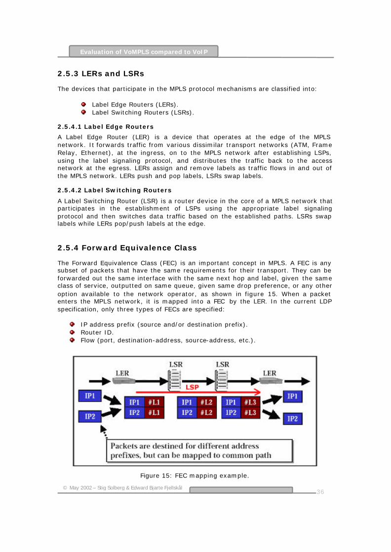
36
© May 2002 – Stig Solberg & Edward Bjarte Fjellskål
Evaluation of VoMPLS compared to VoIP
2.5.3 LERs and LSRs
The devices that participate in the MPLS protocol mechanisms are classified into:
Label Edge Routers (LERs). Label Switching Routers (LSRs).
2.5.4.1 Label Edge Routers
A Label Edge Router (LER) is a device that operates at the edge of the MPLS network. It forwards traffic from various dissimilar transport networks (ATM, Frame Relay, Ethernet), at the ingress, on to the MPLS network after establishing LSPs, using the label signaling protocol, and distributes the traffic back to the access network at the egress. LERs assign and remove labels as traffic flows in and out of the MPLS network. LERs push and pop labels, LSRs swap labels.
2.5.4.2 Label Switching Routers
A Label Switching Router (LSR) is a router device in the core of a MPLS network that participates in the establishment of LSPs using the appropriate label signaling protocol and then switches data traffic based on the established paths. LSRs swap labels while LERs pop/push labels at the edge.
2.5.4 Forward Equivalence Class
The Forward Equivalence Class (FEC) is an important concept in MPLS. A FEC is any subset of packets that have the same requirements for their transport. They can be forwarded out the same interface with the same next hop and label, given the same class of service, outputted on same queue, given same drop preference, or any other option available to the network operator, as shown in figure 15. When a packet enters the MPLS network, it is mapped into a FEC by the LER. In the current LDP specification, only three types of FECs are specified:
IP address prefix (source and/or destination prefix). Router ID. Flow (port, destination-address, source-address, etc.).
Figure 15: FEC mapping example.
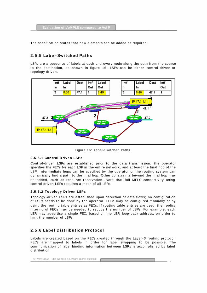
37
© May 2002 – Stig Solberg & Edward Bjarte Fjellskål
Evaluation of VoMPLS compared to VoIP
The specification states that new elements can be added as required.
2.5.5 Label-Switched Paths
LSPs are a sequence of labels at each and every node along the path from the source to the destination, as shown in figure 16. LSPs can be either control-driven or topology driven.
Figure 16: Label-Switched Paths.
2.5.5.1 Control Driven LSPs
Control-driven LSPs are established prior to the data transmission; the operator specifies the FECs for each LSP in the entire network, and at least the final hop of the LSP. Intermediate hops can be specified by the operator or the routing system can dynamically find a path to the final hop. Other constraints beyond the final hop may be added, such as resource reservation. Note that full MPLS connectivity using control driven LSPs requires a mesh of all LERs.
2.5.5.2 Topology Driven LSPs
Topology-driven LSPs are established upon detection of data flows; no configuration of LSPs needs to be done by the operator. FECs may be configured manually or by using the routing table entries as FECs. If routing table entries are used, then policy filtering of FECs may be needed to reduce the number of LSPs. For example, each LER may advertise a single FEC, based on the LER loop-back-address, on order to limit the number of LSPs.
2.5.6 Label Distribution Protocol
Labels are created based on the FECs created through the Layer-3 routing protocol. FECs are mapped to labels in order for label swapping to be possible. The communication of label binding information between LSRs is accomplished by label distribution.

38
© May 2002 – Stig Solberg & Edward Bjarte Fjellskål
Evaluation of VoMPLS compared to VoIP
Label distribution can occur either by piggybacking binding information on an existing routing protocol, or through the creation of a dedicated LDP. The LSR receiving this binding information would, assuming the information comes from the correct next hop, insert the label value into the label information base associated with the corresponding FEC, as shown in figure 17, note that LSR1 and LSR3 are actually LERs which binds the FEC prefix to the label.
Figure 17: Label Distribution. Two methods of Label Distribution can take place using either Downstream Unsolicited Label Distribution or Downstream-on-Demand Label Distribution.
2.5.6.1 Downstream Unsolicited Label Distribution (DU)
As shown in figure 18, LSR2 is being the downstream of LSR1. They are said to have an “LDP adjacency”. When LSR2 discovers a ‘next hop’ for a particular FEC, it generates a label for it and communicates the binding to LSR1, which inserts it into its forwarding tables.
Figure 18: Downstream Unsolicited Label Distribution.
2.5.6.2 Downstream-on-Demand Label Distribution (DoD)
As shown in figure 19, LSR1 recognizes LSR2 as its next-hop for a FEC and sends it a request for binding the FEC to a label. If LSR2 recognizes the FEC and has a next hop for it, it creates a binding and replies to LSR1.

39
© May 2002 – Stig Solberg & Edward Bjarte Fjellskål
Evaluation of VoMPLS compared to VoIP
Figure 19: Downstream-on-Demand Label Distribution.
2.5.6.3 Distribution Control
MPLS defines two modes for the distribution of labels to neighboring LSRs, which are Independent Distribution Control and Ordered Distribution Control. In the following cases, the LSR could be, in theory, operating in either DoD or DU mode. In practice, real implementation tends to use one of the following:
DU, Liberal and either Independent or Ordered. DoD, Conservative, Ordered.
2.5.6.4 Independent Distribution Control
In this mode, each LSR makes independent decision on when to generate labels and communicate them to upstream peers. Once the next hop is recognized, the LSR communicate the Label-FEC binding to its peers. LSP is formed as incoming and outgoing labels are spliced together. With Independent Distribution Control, labels can be exchanged throughout the network with less delay since it does not depend on the availability of the egress node; however the availability of all hops in the path to the destination is not guaranteed. From a practical standpoint, independent label distribution is typically implemented by utilizing the forwarding table entries as FECs and issues mapping for all entries. Filtering may be used to limit the number and type of entries that are advertised as labels.
2.5.6.5 Ordered Distribution Control
In this mode, a LSR communicates the Label-FEC binding to its peers if it is the egress router of that particular FEC or, it has received the label binding from an upstream LSR. The LSP formation then flows from egress to ingress. This mode is typical for ATM-LSRs. Ordered Distribution Control, on the other hand, requires that label mappings can occur only sequentially from the upstream LSR, so the availability of the entire path is guaranteed.
2.5.7 Label Retention
A LSR may receive label bindings from multiple LSRs, and some of these bindings may come from LSRs that are not the valid next-hop for the given FEC, as shown in figure 20. “Valid next-hop” denotes the best next-hop. MPLS defines two methods for the treatment of these “unwanted” label bindings called Liberal Label Retention and Conservative Label Retention. [31]

40
© May 2002 – Stig Solberg & Edward Bjarte Fjellskål
Evaluation of VoMPLS compared to VoIP
Figure 20: Bindings received from multiple LSRs. [31]
MPLS is rapidly becoming a key technology for use in core networks, i.e. backbone, including converged data and voice networks. MPLS does not replace IP routing, but works alongside existing and future routing technologies to provide very high-speed data forwarding between LSRs together with reservation of bandwidth for traffic flows with differing QoS requirements. The basic operation of a MPLS network is shown in figure 21 below.
Figure 21: Two LSPs in a MPLS Network.
MPLS uses a technique known as label switching to forward data through the network. A small, fixed-format label is inserted in front of each data packet on entry into the MPLS network. At each hop across the network, the packet is routed based on the value of the incoming interface and label, and dispatched to an outwards interface with a new label value.

41
© May 2002 – Stig Solberg & Edward Bjarte Fjellskål
Evaluation of VoMPLS compared to VoIP
The path that data follows through a network is defined by the transition in label values, as the label is swapped at each LSR. Since the mapping between labels is constant at each LSR, the path is determined by the initial label value. Such a path is called a LSP. MPLS may also be applied to data switching technologies that are not packet based. The path followed by data through the network is still defined by the transition of switching labels and so is still legitimately called a LSP. However, these non-packet labels (such as wavelength identifiers or timeslots in optical networks) are only used to set up connections, known as crossconnects, at the LSRs. Once the cross-connect is in place, all data can be routed without being inspected hence there is no need to place the label value in each packet. Viewed another way, the wavelength or timeslot is itself the label. At the ingress to a MPLS network, each packet is examined to determine which LSP it should use and hence what label to assign to it. This decision is a local matter but is likely to be based on factors including the destination address, the QoS requirements and the current state of the network. This flexibility is one of the key elements that make MPLS so useful. The set of all packets that are forwarded in the same way is known as a Forwarding Equivalence Class (FEC). One or more FECs may be mapped to a single LSP. Figure 21 shows two data flows from host X: one to Y, and one to Z. Two LSPs are shown.
LSR A is the ingress point (LER) into the MPLS network for data from host X. When it receives packets from X, LSR A determines the FEC for each packet deduces the LSP to use and adds a label to the packet. LSR A then forwards the packet on the appropriate interface for the LSP.
LSR B is an intermediate LSR in the MPLS network. It simply takes each labeled packet and uses the pairing {incoming interface, label value} to decide the pairing {outgoing interface, label value} with which to forward the packet. This procedure can use a simple lookup table that can be implemented in hardware - together with the swapping of label value and forwarding of the packet. This allows MPLS networks to be built on existing label switching hardware such as ATM and Frame Relay. This way of forwarding data packets is potentially much faster than examining the full packet header to decide the next hop (which is the case for IP).
In the example, each packet with label value 21 will be dispatched out of the interface towards LSR D, bearing label value 47. Packets with label value 17 will be re-labeled with value 11 and sent towards LSR C.
LSR C and LSR D act as egress LSRs (LERs) from the MPLS network. These LSRs perform the same lookup as the LSRs, but the {outgoing interface, label value} pair marks the packet as exiting the LSP. The egress LSRs strip the labels from the packets and forward them using layer 3 routing (i.e. IP routing).

42
© May 2002 – Stig Solberg & Edward Bjarte Fjellskål
Evaluation of VoMPLS compared to VoIP
So, if LSR A identifies all packets for host Z with the upper LSP and labels them with value 21, they will be successfully forwarded through the network, emerging from the LSP at D, which then forwards the packets through IP to Z. [30]
2.5.8 MPLS forwarding
The essentials of MPLS forwarding can be illustrated by an example. The aim is to trace how an IP packet arriving at the ingress of a MPLS network is transported to the egress of the network. The sequence followed is:
1) The IP packet enters at the ingress to the MPLS network. 2) The packet is assigned to a path and a label attached. This process first
classifies the packet and then adds the label. In fact all of the packets that fall into the same classification get the same label. More formally we say a packet is assigned to a FEC. The labeled packet is sent to the next MPLS node.
3) This node looks at the label - the IP header is not examined. 4) The next hop is chosen by reference to a label forwarding table. This table
has entries for the incoming interface and label value and corresponding entries for the output interface and the outgoing label value. Thus, the table entries may determine that a packet arriving on (say) interface 1 with label value (say) x will be switched to an output interface (say) 7 with a label value of (say) u.
5) The new label is written and the packet sent on its way to the next MPLS node.
6) This process continues until the packet reaches the last MPLS node (egress).
7) The label is stripped (popped). This may expose another label or an IP header. In the latter case, the packet is delivered to the final destination using standard IP procedures.
[33]
2.5.9 Some MPLS Features
FEATURE
DEFINITION
BENEFIT
Traffic Engineering with RSVP for short cut tunnel creation.
Provides manual or automatic path selection with bandwidth reservation.
Controls prioritization of traffic flows. Provides predictable network behavior during network failures.
Dynamic FEC -to-LSP binding.
The network automatically maps Forwarding Equivalent Classes (FECs) to MPLS Label Switched Paths (LSPs).
Eliminates routing loops and configuration steps. Aggregates traffic that shares the same QoS parameters for superior network efficiency and performance.
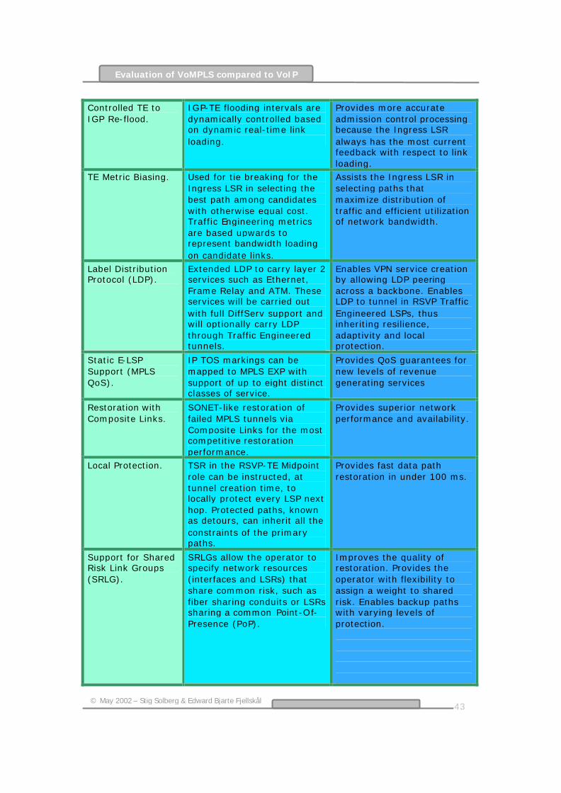
43
© May 2002 – Stig Solberg & Edward Bjarte Fjellskål
Evaluation of VoMPLS compared to VoIP
Controlled TE to IGP Re-flood.
IGP-TE flooding intervals are dynamically controlled based on dynamic real-time link loading.
Provides more accurate admission control processing because the Ingress LSR always has the most current feedback with respect to link loading.
TE Metric Biasing. Used for tie breaking for the Ingress LSR in selecting the best path among candidates with otherwise equal cost. Traffic Engineering metrics are based upwards to represent bandwidth loading on candidate links.
Assists the Ingress LSR in selecting paths that maximize distribution of traffic and efficient utilization of network bandwidth.
Label Distribution Protocol (LDP).
Extended LDP to carry layer 2 services such as Ethernet, Frame Relay and ATM. These services will be carried out with full DiffServ support and will optionally carry LDP through Traffic Engineered tunnels.
Enables VPN service creation by allowing LDP peering across a backbone. Enables LDP to tunnel in RSVP Traffic Engineered LSPs, thus inheriting resilience, adaptivity and local protection.
Static E-LSP Support (MPLS QoS).
IP TOS markings can be mapped to MPLS EXP with support of up to eight distinct classes of service.
Provides QoS guarantees for new levels of revenue generating services
Restoration with Composite Links.
SONET-like restoration of failed MPLS tunnels via Composite Links for the most competitive restoration performance.
Provides superior network performance and availability.
Local Protection. TSR in the RSVP-TE Midpoint role can be instructed, at tunnel creation time, to locally protect every LSP next hop. Protected paths, known as detours, can inherit all the constraints of the primary paths.
Provides fast data path restoration in under 100 ms.
Support for Shared Risk Link Groups (SRLG).
SRLGs allow the operator to specify network resources (interfaces and LSRs) that share common risk, such as fiber sharing conduits or LSRs sharing a common Point-Of-Presence (PoP).
Improves the quality of restoration. Provides the operator with flexibility to assign a weight to shared risk. Enables backup paths with varying levels of protection.

44
© May 2002 – Stig Solberg & Edward Bjarte Fjellskål
Evaluation of VoMPLS compared to VoIP
Make-Before-Break.
Technique whereby the primary or midpoint (in the case of local protection) is able to signal a new optimized LSP to replace an active LSP. The signalling ingress can reroute active traffic onto the optimized path with no lost data.
Provides an essential building block for adaptivity (reoptimization) of both active and backup LSPs. Enables the network operator to continually optimize the Traffic Engineering path selection with no impact to subscriber traffic.
Per-LSR/LSP Resiliency Parameters.
Granular level of resiliency parameter options that can be applied on an entire LSR or independently on a per LSP basis.
Provides unparalleled resiliency, which is the ability to respond to network failures.
Per-LSR/LSP adaptivity.
True network adaptivity can be supported through manual or automated LSP rerouting to rebalance current bandwidth loading across all available and suitable resources.
Provides continuous monitoring of bandwidth loading for subsequent re-optimization based on a user supplied adaptivity time. Provides full consideration of user supplied constraints an entire LSR or LSP basis.
Label Swapping. Simultaneous label operations and multiple route lookups in a single clock cycle may be implemented. Obviates the requirement for signalling null labels for the last hop of the LSP.
Eliminates Penultimate Hop Popping when the router is the tunnel egress. Enables end-to-end QoS and statistical integrity from ingress to egress.
Scalability. The ingress may support thousands LSPs per interface. The router midpoint may support even more LSPs per interface.
Provides unmatched scalability for the most demanding MPLS topologies.
MPLS Hardware Support.
The line cards must support MPLS.
Offers maximum flexibility in the creation of next generation MPLS networks.
45
© May 2002 – Stig Solberg & Edward Bjarte Fjellskål
Evaluation of VoMPLS compared to VoIP
2.6 VoMPLS
2.6.1 Introduction
2.6.1.1 Purpose
There are many possible arrangements in which voice may be carried in an MPLS environment. Two of the most commonly discussed arrangements are:
Voice over IP (VoIP) over MPLS (VoIPoMPLS). In this case, the typical protocol stack contains voice data encapsulated in IP layer protocols (e.g., RTP/UDP/IP) followed by encapsulation in the MPLS protocol. Compressed headers may be utilized in some implementations. The result is then conveyed by an MPLS transport arrangement such as FR, ATM, PPP, or Ethernet.
Voice directly over MPLS (VoMPLS) (without the IP encapsulation of the voice packet). In this case, the typical protocol stack would consist of voice data encapsulated in the MPLS protocol on top of an MPLS transport arrangement such as FR, ATM, PPP, or Ethernet.
The first arrangement, VoIPoMPLS, is essentially a method of implementing VoIP and is largely supported by existing IETF standards. VoIPoMPLS is not the method taken in consideration in this thesis. The second arrangement, VoMPLS, provides a very efficient transport mechanism for voice in the MPLS environment and is the method taken in consideration in this report. There are many similarities to this arrangement and other architectures in use today for VoATM and VoFR. The purpose of the VoMPLS method is to define how a voice payload is encapsulated directly in the MPLS frame. It includes the definition of a VoMPLS header format supporting various payload types including Audio, Dialed digits (DTMF - Dual Tone Multi Frequency), Channel Associated Signaling and a Silence insertion descriptor. The defined VoMPLS – Bearer Transport header formats are different from RTP formats that are used in Voice over IP.
2.6.1.2 Scope and Overview
MPLS is defined to support the transport of digital voice payloads. Frame formats and procedures required for voice transport are described in this chapter. The following functions are addressed:
Transport of uncompressed and compressed voice within the payload of a MPLS frame. Support for a diverse set of voice compression algorithms;
Silence removal and Silence insertion descriptors; DTMF information; and Channel associated signaling bits.
Algorithms for defining encoding audio streams are not described. We only refer to existing algorithms and specify how the bits that they output are conveyed within a MPLS packet structure. Support for the unique needs of the different voice

46
© May 2002 – Stig Solberg & Edward Bjarte Fjellskål
Evaluation of VoMPLS compared to VoIP
compression algorithms is accommodated with algorithm-specific transfer syntax definitions. These definitions establish algorithm specific frame formats and procedures. Transport of supporting information for voice communication, such as signaling indications and dialed digits, is also provided through the use of transfer syntax definitions specific to the information being sent. Signaling protocols will not be described; neither will call routing, equipment aspects, performance guidelines, or implementation techniques. In this report, VoMPLS shall refer only to the arrangement of Voice (without IP encapsulation) over MPLS.
2.6.2 Reference Architecture
2.6.2.1 General
Figure 22 identifies the Reference Architecture for VoMPLS. The MPLS network contains a number of Gateway (GW) devices, LSR, and LSP. An example LSP is shown as a solid line in the figure. Gateways may be directly connected to each other or indirectly connected through a number of LSRs.
Figure 22: VoMPLS Reference Architecture A simple architecture is all that is required in order to understand the application of VoMPLS. It is not the intent of this chapter to specify the internal details of MPLS networks, the signaling required supporting VoMPLS, or the architecture or functions of gateways and routers. There are many different examples of how VoMPLS may be implemented and deployed in a network. The intent of the reference architecture is to support all possible deployments of VoMPLS. The GW contains the functionality of a LER as well as many other functions. The Gateway device interfaces the MPLS network with:
Other media (i.e., Time Division Multiplexing (TDM), IP, ATM, etc.);

47
© May 2002 – Stig Solberg & Edward Bjarte Fjellskål
Evaluation of VoMPLS compared to VoIP
Another MPLS network; Other networks (e.g., VoIP, PSTN, VoATM, etc.); and With access devices.
This architecture must be capable of supporting many different LSP bearer arrangements to convey voice payloads in an MPLS environment. For example:
One arrangement may be an end-to-end LSP established between two voice devices existing within a single MPLS domain.
A second arrangement may be a LSP that has been established to support only a portion of the voice connection between the end devices.
In the second case, multiple LSPs may need to be concatenated to form an end-to-end connection; or perhaps interworking between a LSP and another type of bearer may be required. This is a common occurrence in the current ISDN/PSTN environment where multiple service providers may be involved in carrying the call between the end devices. A MPLS domain might exist between the entry and exit gateway nodes of the service provider network. LSPs are created between these network gateways to carry calls in a voice trunking arrangement.
2.6.3 Multiplexing voice calls onto MPLS LSPs
Multiple voice calls may be transported over a LSP. Two types of VoMPLS subframes are defined, Primary and Control, and may be transmitted as required. Multiple primary subframes may be multiplexed within a single MPLS frame. The control subframes are not multiplexed and are sent separately; that is, only one control subframe at a time may be carried within a MPLS frame. Primary subframes and control subframes are not multiplexed together within a single MPLS frame. A primary payload contains the traffic that is fundamental to the operation of a connection identified by a Channel Identifier (CID). It includes encoded voice and silence information descriptor(s). Primary payloads are variable length subframes. Control subframes may be sent to support the primary payload (e.g., dialed digits for a primary payload of encoded voice) and other control functions. These payloads are differentiated from the primary payload by a Payload Type value in the subframe header. A range of payload type values is assigned to primary payload and control payloads. Control subframes are fixed length and most of them are sent with a triple redundant transmission with a fixed interval between them. The CID and payload type fields are common to both primary and control payload formats.
2.6.3.1 Primary Subframe
The MPLS frame structure allowing the multiplexing of primary subframes of Voice over MPLS calls is shown in figure 23.

48
© May 2002 – Stig Solberg & Edward Bjarte Fjellskål
Evaluation of VoMPLS compared to VoIP
Figure 23: LSP Structure for Multiplexing Primary subframes of Voice Calls A typical VoMPLS multiplexing structure consists of a mandatory outer label, zero or more inner labels, and one or more VoMPLS primary subframes consisting of a 4-octet header and variable length primary payload. The Channel ID (CID) allows up to 248 VoMPLS calls to be multiplexed within a single LSP. At least one LSP must be created to convey VoMPLS calls; thus the use of an outer label is Mandatory. As an implementation option, additional inner LSPs may be created using stacked labels. Figure 24 depicts an example VoMPLS primary frame structure of a single LSP that is used to convey from one to 248 VoMPLS channels. Note that a unique CID identifies each VoMPLS subframe but that the primary subframes may be transmitted in any order whenever information for a channel is available.
Figure 24: Single-LSP structure for multiplexing Primary Payloads of VoMPLS calls In order to establish the single-LSP Voice over MPLS bearer structure depicted in figure 24 the procedure is as follows:
1) A bi-directional LSP is created either by manual provisioning or by using a MPLS control protocol (e.g., CR-LDP, RSVP-TE).
2) As voice or audio connections arrive at the LER, a CID value is assigned to
the connection (multiplexed) within the LSP. This is accomplished by either:
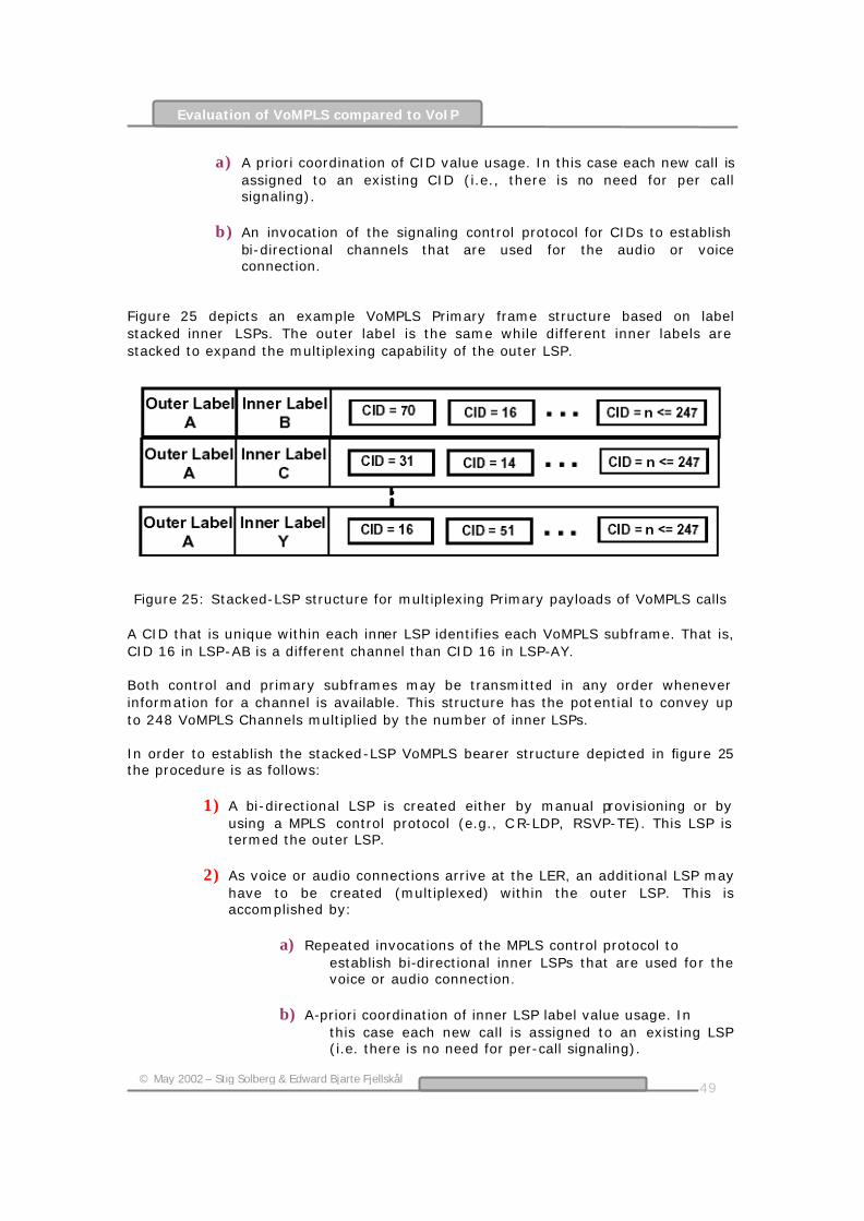
49
© May 2002 – Stig Solberg & Edward Bjarte Fjellskål
Evaluation of VoMPLS compared to VoIP
a) A priori coordination of CID value usage. In this case each new call is assigned to an existing CID (i.e., there is no need for per call signaling).
b) An invocation of the signaling control protocol for CIDs to establish
bi-directional channels that are used for the audio or voice connection.
Figure 25 depicts an example VoMPLS Primary frame structure based on label stacked inner LSPs. The outer label is the same while different inner labels are stacked to expand the multiplexing capability of the outer LSP.
Figure 25: Stacked-LSP structure for multiplexing Primary payloads of VoMPLS calls
A CID that is unique within each inner LSP identifies each VoMPLS subframe. That is, CID 16 in LSP-AB is a different channel than CID 16 in LSP-AY. Both control and primary subframes may be transmitted in any order whenever information for a channel is available. This structure has the potential to convey up to 248 VoMPLS Channels multiplied by the number of inner LSPs. In order to establish the stacked-LSP VoMPLS bearer structure depicted in figure 25 the procedure is as follows:
1) A bi-directional LSP is created either by manual provisioning or by using a MPLS control protocol (e.g., C R-LDP, RSVP-TE). This LSP is termed the outer LSP.
2) As voice or audio connections arrive at the LER, an additional LSP may
have to be created (multiplexed) within the outer LSP. This is accomplished by:
a) Repeated invocations of the MPLS control protocol to establish bi-directional inner LSPs that are used for the voice or audio connection.
b) A-priori coordination of inner LSP label value usage. In
this case each new call is assigned to an existing LSP (i.e. there is no need for per-call signaling).
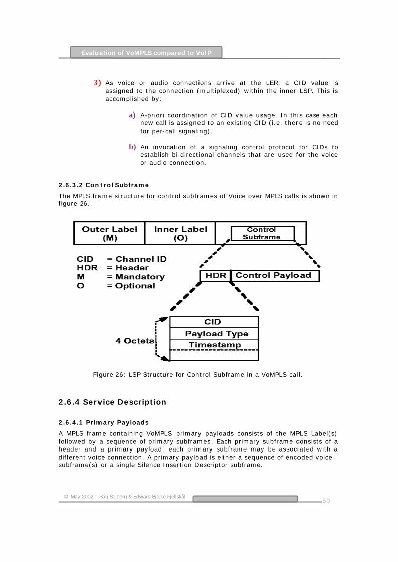
50
© May 2002 – Stig Solberg & Edward Bjarte Fjellskål
Evaluation of VoMPLS compared to VoIP
3) As voice or audio connections arrive at the LER, a CID value is
assigned to the connection (multiplexed) within the inner LSP. This is accomplished by:
a) A-priori coordination of CID value usage. In this case each new call is assigned to an existing CID (i.e. there is no need for per-call signaling).
b) An invocation of a signaling control protocol for CIDs to
establish bi-directional channels that are used for the voice or audio connection.
2.6.3.2 Control Subframe
The MPLS frame structure for control subframes of Voice over MPLS calls is shown in figure 26.
Figure 26: LSP Structure for Control Subframe in a VoMPLS call.
2.6.4 Service Description
2.6.4.1 Primary Payloads
A MPLS frame containing VoMPLS primary payloads consists of the MPLS Label(s) followed by a sequence of primary subframes. Each primary subframe consists of a header and a primary payload; each primary subframe may be associated with a different voice connection. A primary payload is either a sequence of encoded voice subframe(s) or a single Silence Insertion Descriptor subframe.

51
© May 2002 – Stig Solberg & Edward Bjarte Fjellskål
Evaluation of VoMPLS compared to VoIP
2.6.4.2 Encoded Voice
This service element conveys voice information supplied by the service user. The voice information is packaged according to the rules specified by voice transfer syntax.
2.6.4.2 Silence Information Descriptor
Silence Information Descriptor (SID) subframes indicates the end of a talk-spurt and conveys comfort noise generation parameters. These SID indications support Voice Activity Detection (VAD) and silence suppression schemes. When VAD is utilized, a SID subframe may optionally be transmitted following the last encoded voice subframe of a talk-spurt. Reception of a SID subframe after a voice subframe may be interpreted as an explicit indication of end of talk-spurt. In addition, SID subframes may be transmitted at any time during the silence interval to update comfort noise generation parameters. The SID payload is defined for Pulse Code Modulation (PCM) and Adaptive Differential Pulse Code Modulation (ADPCM) encoding. SID subframes should not be sent if VAD is not utilized. The comfort noise analysis and synthesis as well as the VAD and discontinuous transmission algorithms are implementation specific.
2.6.5 Control Payload
The control payload consists of a single control subframe. The control subframe consists of a header and a control payload; the control subframe is associated with a specific voice connection.
2.6.5.1 Dialed Digits
This service element transparently conveys DTMF, or other dialed digits supplied by the service user. These digits may be sent during the voice call setup or following call establishment to transfer in-band tones. Since some of the low bit-rate coding algorithms used may not properly pass the DTMF tones or other dialed digits, special capabilities must be employed to ensure the tones are properly conveyed.
2.6.5.2 Signaling Bits (Channel Associated Signaling)
This service element transparently conveys signaling bits supplied by the service user. These bits may indicate seizure and release of a connection, dial pulses, ringing, or other information in accordance with the signaling system in use over the transmission facility.
2.6.6 Additional Requirements
2.6.6.1 VoMPLS over ATM
When VoMPLS is operated over an ATM network, it shall follow RFC 3035 “MPLS using LDP and ATM switching”.

52
© May 2002 – Stig Solberg & Edward Bjarte Fjellskål
Evaluation of VoMPLS compared to VoIP
2.6.7 Frame Formats
2.6.7.1 General Format
The CID of a primary subframe or control subframe will identify the connection and serves as channel identification. As specified in Section 3, there are two types of protocol data units that are transported in a MPLS payload carrying VoMPLS:
Primary payload with voice or audio information (e.g., encoded voice, Generic Silence Insertion Descriptor (SID), etc) and
Control payload (e.g., signaling payload (dialed digits, channel associated signaling bits), etc).
2.6.7.2 Format of the Primary Subframe
The format of the primary subframe is shown in figure 27. To maintain word (32 bits) alignment, the payload information must be a multiple of 4 octets. If the payload is not a multiple of 4 octets, up to 3 PAD octets are included to make it word aligned. As specified, a primary payload is either a sequence of encoded voice subframes or a single Silence Insertion Descriptor subframe. The encoded voice subframe consists of one or more audio frames containing sample intervals or frames. The sample intervals or frames are placed sequentially in an encoded voice subframe. If the number of sample intervals or frames in a payload is more than one, the next interval or frame starts on the next octet after the previous interval or frame. PAD octets are only used in the last word of the payload if needed for word alignment.
Figure 27: Format of the Primary payload
The fields in the header of primary payload frames are specified as follows:
a) Channel Identifier (CID): This Channel Identifier indicates uniquely a voice or audio
connection within the LSP of Voice over MPLS. The values "0" to "247" can be used to identify the VoMPLS
user channels.

53
© May 2002 – Stig Solberg & Edward Bjarte Fjellskål
Evaluation of VoMPLS compared to VoIP
Table 2: Coding of the CID Field.
b) Payload Type:
The payload type field indicates the payload type and encoding algorithm used for the voice or audio. The primary payload type field is coded.
Table 3: Allocation of Payload Type values.
c) Counter:
The counter field provides a counter value at the first sample or frame in an encoded voice subframe. The initial value of the counter is derived from the initial timestamp for the connection. After reaching the maximum unsigned count, the counter wraps around to zero.
d) Length:
The length indicates the number of voice/audio words (32 bits) in the voice frame including the PAD octets. It does not include the 4-octet header.
e) PAD Length (PDL):
The PDL field indicates the number of PAD octets in the last word (4 octets) of the primary payload.
2.6.7.3 Format of the Control Subframe
The format of the control payload frame is shown in figure 28. In order to maintain word (32 bits) alignment, the control frame payload must be multiple of 4 octets. The length of the Control subframe is always inferred from its type.

54
© May 2002 – Stig Solberg & Edward Bjarte Fjellskål
Evaluation of VoMPLS compared to VoIP
Figure 28: Format of the Control payload The fields in the header of Control payload frames are specified as follows:
a) Channel Identifier (CID): Just like the CID for Primary payload.
b) Payload Type:
The payload type field indicates the payload type of control payloads. The payload types for control frames are specified in table 4.
Table 4: Packet Types for Control Payloads
c) Timestamp: The timestamp reflects the sampling time of the control payload and it
is coded in 125 µs units (8 kHz clock). It provides relative time. The initial value of the timestamp is random.
d) Redundancy: The Redundancy field is set to values 0, 1 and 2 respectively for a
packet’s first, second, and third transmission under triple redundancy. Redundancy value 3 indicates no use of triple redundancy, whereby the payload is sent once.
[34]
55
© May 2002 – Stig Solberg & Edward Bjarte Fjellskål
Evaluation of VoMPLS compared to VoIP
2.7 MPLS Traffic Engineering
2.7.1 Introduction
MPLS Traffic Engineering (MPLS-TE) is a key ingredient in delivering end-to-end QoS involves the mapping of aggregated micro-flows across traffic engineered tunnels in the MPLS routing domain. MPLS creates a pre-established connection-oriented path tunnel in advance of the arriving traffic that lends itself to accommodating the particular bandwidth requirements of the data that is flowing across it. MPLS label switched paths are an essential element in delivering end-to-end QoS. Without them, it is not possible to control the path of packet flows from requested packet treatments. [35] MPLS is a new technology that offers to open up the Internet by providing many additional services to applications using i.e. IP. Many of the new services that Internet Service Providers (ISPs) want to offer rely on TE functions. There are currently two label distribution protocols that provide support for Traffic Engineering: Resource ReSerVation Protocol (RSVP) and C R-LDP. Although the two protocols provide a similar level of service, the way they operate is different, and the detailed function they offer is also not consistent. Hardware vendors and network providers need clear information to help them decide which protocol to implement in a Traffic Engineered MPLS network. Each protocol has its champions and detractors, and the specifications are still under development. [36]
2.7.2 Traffic Engineering
TE is the process where data is routed through the network according to a management view of the availability of resources and the current and expected traffic. The CoS and QoS required for the data can also be factored into this process. TE may be under the control of manual operators. They monitor the state of the network and route the traffic or provision additional resources to compensate for problems as they arise. Alternatively, TE may be driven by automated processes reacting to information feedback through routing protocols or other means. TE helps the network provider make the best use of available resources, spreading the load over the layer 2 links, and allowing some links to be reserved for certain classes of traffic or for particular customers. One of the main uses for MPLS will be to allow improved TE on the ISP backbone networks.
2.7.3 Resource Reservation
In order to secure promised services, it is not sufficient simply to select a route that can provide the correct resources. These resources must be reserved to ensure that they are not shared or “stolen” by another LSP. The traffic requirements can be passed during LSP setup (as with constraint-based routing). They are used at each LSR to reserve the resources required, or to fail the setup if the resources are not available.

56
© May 2002 – Stig Solberg & Edward Bjarte Fjellskål
Evaluation of VoMPLS compared to VoIP
2.7.4 Service Level Agreements
Many uses of the Internet require particular levels of service to be supplied. For example, voice traffic requires low delay and very small delay variation (jitter). Video traffic adds the requirement for high bandwidth. Customers increasingly demand service contracts that guarantee the performance and availability of the network. In the past, in order to meet these requirements, network providers have had to over-provision their physical networks. MPLS offers a good way to avoid this issue by allocating the network resources to particular flows using constraint-based routing of LSPs. [36]
2.7.5 The Need for Traffic Engineering
The IP was created as a connectionless network layer protocol that makes no attempt to discriminate between various application types. IP uses traditional Interior Gateway routing Protocols (IGPs) like Intermediate System-to-Intermediate System (IS-IS) and Open Shortest Path First (OSPF) to advertise and build a database of all active links within a routing domain. Successful operation of these networks depends upon the same distributed network state information being disseminated and consistently maintained by all routers within the same autonomous system (AS). Each router uses the same global state information to independently develop its own forwarding table using shortest path constraint-based metrics. The adverse result this creates is to concentrate traffic across a smaller number of optimized data paths to the detriment of other links, which frequently remain underutilized. All arriving data flows on various ingress interfaces on the same node that are bound for the same destination are always consolidated across a common path. The compounded effect of concentrating large data flows across a small number of links often produces traffic bottlenecks. Even in the face of congested links, traditional routing protocols will continue to forward traffic across these same paths until packets are dropped. To accommodate highly interactive application flows with low delay and packet loss thresholds, there is a clear need to more efficiently utilize the available network resources. The process whereby this is accomplished is known as TE and MPLS provides these capabilities.
2.7.6 Constrained Routing
Constrained (-based) routing (CR) is routing based upon QoS needs of the user. The LSPs are set up based on different criteria. Parameters like Peak Rate, Committed Rate, Excess Burst Size, Peak Rate Token Bucket, Committed Data Rate Token Bucket and Weight are taken into consideration when setting up a LSP. It is demand-driven and is aware of the traffic trunk attributes and the attributes of network resources. Each LSR automatically computes an explicit route for each traffic trunk based on the requirements of the trunk’s attributes, subject to the constraints of network resources and the administrative policies of the network. [37]
2.7.7 MPLS-TE description
MPLS-TE attempts to correct the inefficiencies of typical datagram routing protocols by more evenly spreading the flow of traffic across all available resources. Reengineering a conventional datagram network based solely on Layer 3 cost-based
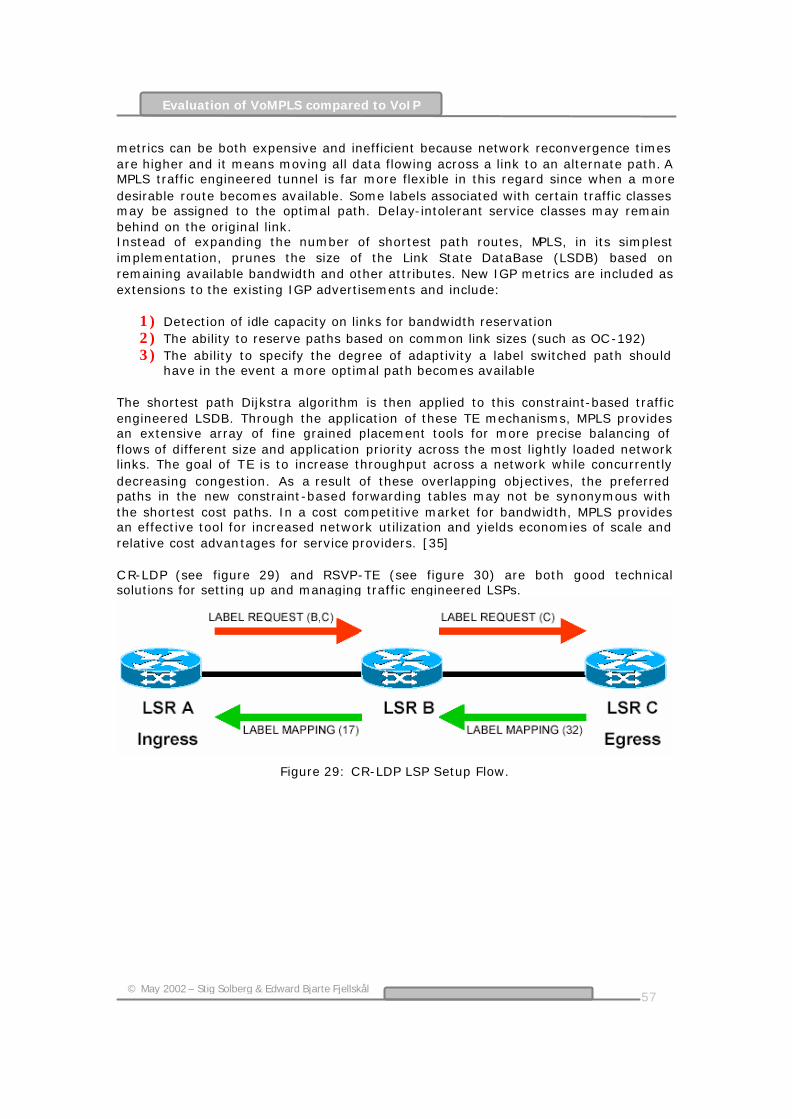
57
© May 2002 – Stig Solberg & Edward Bjarte Fjellskål
Evaluation of VoMPLS compared to VoIP
metrics can be both expensive and inefficient because network reconvergence times are higher and it means moving all data flowing across a link to an alternate path. A MPLS traffic engineered tunnel is far more flexible in this regard since when a more desirable route becomes available. Some labels associated with certain traffic classes may be assigned to the optimal path. Delay-intolerant service classes may remain behind on the original link. Instead of expanding the number of shortest path routes, MPLS, in its simplest implementation, prunes the size of the Link State DataBase (LSDB) based on remaining available bandwidth and other attributes. New IGP metrics are included as extensions to the existing IGP advertisements and include:
1) Detection of idle capacity on links for bandwidth reservation 2) The ability to reserve paths based on common link sizes (such as OC-192) 3) The ability to specify the degree of adaptivity a label switched path should
have in the event a more optimal path becomes available The shortest path Dijkstra algorithm is then applied to this constraint-based traffic engineered LSDB. Through the application of these TE mechanisms, MPLS provides an extensive array of fine grained placement tools for more precise balancing of flows of different size and application priority across the most lightly loaded network links. The goal of TE is to increase throughput across a network while concurrently decreasing congestion. As a result of these overlapping objectives, the preferred paths in the new constraint-based forwarding tables may not be synonymous with the shortest cost paths. In a cost competitive market for bandwidth, MPLS provides an effective tool for increased network utilization and yields economies of scale and relative cost advantages for service providers. [35] C R-LDP (see figure 29) and RSVP-TE (see figure 30) are both good technical solutions for setting up and managing traffic engineered LSPs.
Figure 29: CR-LDP LSP Setup Flow.

58
© May 2002 – Stig Solberg & Edward Bjarte Fjellskål
Evaluation of VoMPLS compared to VoIP
Figure 30: RSVP LSP Setup Flow.
Some key differences in the structure of the protocols and the underlying transport mean that the support that the protocols can provide will never converge completely. These differences and the differences in speed and scope of deployment will be the main factors that influence vendors when they are selecting a protocol. The choice between RSVP and CR-LDP should be guided by the function of the target system.
What LSP setup model will be used? How stable are the LSPs – do they represent permanent trunks or
short-duration calls? How large and complex is the network? Is this a stand-alone network or must the components interwork with
other hardware and other networks? A final consideration must be the robustness of the hardware solution.
What level of fault tolerance is required? How important is high availability?
[37]
2.7.8 Provisioning QoS over Traffic Engineered MPLS Backbones
The final ingredient in the delivery of end-to-end QoS involves the mapping of aggregated micro-flows across traffic engineered tunnels in the MPLS routing domain. MPLS creates a pre-established connection-oriented path tunnel in advance of the arriving traffic that lends itself to accommodating the particular bandwidth requirements of the data that is flowing across it. MPLS LSPs are an essential element in delivering end-to-end QoS. The process of assigning traffic flows to traffic engineered tunnels begins in the conventional fashion with the flooding of state information by IGP routing protocols. After the C R LSDB has established the optimal forwarding path, a signaling protocol such as RSVP-TE and CR-LDP must configure flow-state in the nodes along the path before traffic can begin to be forwarded. Utilizing enhanced RSVP signaling in a MPLS DiffServ domain differs from IntServ in terms of aggregation. Enhanced signaling can also be used to apportion link resources directly to the link -shares being requested by various TCs. New extensions to IGP routing protocols are used to communicate available bandwidth capacity and to provide an early warning system for potential congestion as network conditions change. Figure 31 below illustrates the chain of events as singular micro-flows from an IntServ domain are consolidated into

59
© May 2002 – Stig Solberg & Edward Bjarte Fjellskål
Evaluation of VoMPLS compared to VoIP
aggregate TCs and mapped across MPLS traffic trunks in a DiffServ backbone topology. [35]
Figure 31: Mapping Per-Hop behaviors (PHBs) into MPLS Labels.
As depicted in the above figure, DiffServ PHB Scheduling C lasses (PSC s) are mapped into MPLS labels at the ingress core transit router. Arriving packets include DiffServ Code Points (DSCPs) settings that maintain the requested QoS requirements established by local policy management tools at the network edge. DSCPs signal the hop-by hop instructions for internal scheduling, packet treatment and drop preferences. At the ingress LSR, the requested PSC and drop preferences are mapped into the 3 bit experimental (EXP) field within the MPLS Shim Header. At every label switched router in the MPLS domain, the service provider configures the bi-directional mapping of DSCPs into specific values of EXP bits. The service provider is also responsible for configuring the scheduling behavior on every interface for all scheduling classes supported over LSPs. Once a traffic flow is mapped into a LSP, the
Egress LSR Ingress LSR
MPLS Core Network
Label 18
Label 19
DiffServ Routing Domain
DiffServ Routing Domain
Per- Aggregate QoS
DiffServ Admission Control
IntServ Edge Aggregation Network
IntServ Edge Network
Per-Flow QoS
Workstation Workstation
Path Msg RESV
Msg
Next Hop Label Fwd Table
Sys Type
Output Label
EXP
EF
AF
18
19
Exp 0
Exp 0-3

60
© May 2002 – Stig Solberg & Edward Bjarte Fjellskål
Evaluation of VoMPLS compared to VoIP
Layer 3 payload becomes opaque to successive LSRs in the MPLS domain. Henceforth, all forwarding and packet treatments are based on the contents of the EXP field. In figure 31, Label 18 is used to transport an expedited forwarding class of service associated with circuit emulation voice traffic. To accommodate the interactive nature of this application, a committed information rate is established by reserving a fixed amount of link bandwidth and maximum precautions are taken on the various network elements to minimize both queuing delay and jitter. By contrast, Label 19 is used to carry a blend of traffic consisting of interactive video, asynchronous fax traffic and elastic bulk file transfers. At the ingress label switched router, it is discovered that the File Transfer Protocol (FTP) traffic is bursting to consume more than its fair share of bandwidth because it was not policed at the network edge. Although it continues to receive the same scheduling treatment as the fax traffic, it now stands a higher likelihood of being dropped. The two proposed IETF methods for aggregating DiffServ marked packets into MPLS tunnels for QoS; Label inferred LSPs (L-LSPs) and Experimental bit inferred LSPs (E-LSPs) are described below. [35]
2.7.9 Path re-optimization
When a path is less than optimal, it becomes important to try to re-optimize a LSP in the background. For instance, if a high-priority LSP preempts a medium-priority LSP, a less-than-optimal medium-priority LSP might be established. Automatic re-optimization ensures that the medium-priority LSP will be reestablished with its original characteristics when resources become available.
2.7.10 E-LSPs for Mapping DiffServ to MPLS
E-LSPs are traffic engineered tunnels that are used to support up to 8 behavior aggregates. E-LSPs rely entirely on the 3 bits in the Experimental Field to identify drop preference and scheduling class. The E-LSP is based on a direct mapping of up to 8 DiffServ codepoints into a label switched path with a single label. DSCP consists of 6bits (64 different possibilities) and E-LSP consists of 3 bits (8 possibilities). Therefore all the DSCP possibilities can not be mapped over to E-LSP. Although consolidation of multiple DiffServ codepoints within the same tunnel has the ability to conserve label space and reduce label establishment signaling, it is not desirable for MPLS fast reroute service, since all eight possible EXP markings share a common tunnel. Given this constraint, the use of E-LSPs is no better than standard IGPs for distributing only preferred flows on selected back-up paths. Thus if the network operator wishes to forward constant bit rate services over a pre-established backup path, they should do so using L-LSP paths.
2.7.11 L-LSPs for Mapping DiffServ to MPLS
L-LSPs can be used to transport groupings of more than 8 behavior aggregates. This method requires that an association of specific DiffServ codepoints to LSPs be pre-established prior to traffic being forwarded. The strength of L-LSPs is their relationship to fast reroute restoration services. Packets arriving at the ingress LSR with DiffServ codepoints that dictate premium service will be labeled for paths that are fast reroute capable. In this case, a single label is used to represent a single scheduling class. The cost of increased provisioning flexibility is more rapid label

61
© May 2002 – Stig Solberg & Edward Bjarte Fjellskål
Evaluation of VoMPLS compared to VoIP
depletion and consumption of network resources, so this form of L-LSP should be used sparingly. Other non-premium traffic headed to the same destination will not require fast reroute and can be consolidated over parallel L-LSP paths. L-LSPs can be used to support numerous packet treatments because they can easily be assigned to singular or consolidated scheduling classes. Using these flexible bandwidth management tools, the network operator may forward multiple traffic classes over the same or multiple paths to insure that diverse traffic with different service requirements receives the appropriate treatment requested by the SLA.
2.7.12 Fast Re-Routing
The fast reroute recovery mechanism does not require the notification of the ingress LSR. In fact no signaling is required at the time that the failure is detected. The node that detects the failure is also the node performing the repair. In addition, as in protection switching, the backup pat hs are pre-signaled and the required resources are pre-reserved. [38]
Figure 32: Bypass tunnel concept. Figure 32 depicts a series of bypass tunnels which backup two primary LSPs, A and B. A key requirement for the bypass tunnel, to provide protection to multiple LSPs, is the use of label stacking. In referring to Figure 5, if the link between LSR 1 and LSR 2 should fail, LSR 1 (the Point of Local Repair (PLR)) must redirect labeled packets over the bypass tunnel. Label stacking is proposed to solve the problem of LSR 10 (the merge node) correctly associating labeled packets arriving from LSR 7 (over the bypass tunnel) as belonging to the original tunnel (I-1-2-5-8-10-E). LSR 1 must label packets intended for tunnel A with the label that LSR 10 (the merge node) expects to be receiving from LSR 8. LSR 1 must then push a second label onto the packet intended for LSR 4 (the next hop of the bypass tunnel). Packets for Tunnel A are then shuttled over the bypass tunnel using normal label switching. At label switching router 10 a label stack “POP” occurs exposing the label that LSR 10 is expecting from LSR 8, thus closing the circuit around the failure. [39]

62
© May 2002 – Stig Solberg & Edward Bjarte Fjellskål
Evaluation of VoMPLS compared to VoIP
2.7.13 Summary
This chapter discussed several methods whereby service providers can leverage QoS and MPLS to gain operational network efficiencies and enable higher value-added pricing models founded upon network aware treatment of applications. With traffic differentiated by user and application, network resources can be provisioned to support more granular levels of service. The new service levels will deliver the flexibility for network operators to offer numerous pricing models. The end result is more ways for network operators to generate incremental sources of revenue. The same tools will also allow end users to better manage their diverse voice, video and data application requirements across a ubiquitous network. With all of these incentives, it is clearly in the best interests of service providers to work cohesively together to deliver end-to-end SLAs across network domains.

63
© May 2002 – Stig Solberg & Edward Bjarte Fjellskål
Evaluation of VoMPLS compared to VoIP
3 Evaluation of VoMPLS compared to VoIP
3.1 Introduction
This section is meant as an evaluation of VoMPLS compared to VoIP. All through this section there will be a conspicuous focusing on pure MPLS techniques and features. The reason for this approach can be explained due to the fact that VoMPLS is targeting the same area as pure VoIP, but with the added advantages of a MPLS core. The same argument yields for VoIP, where the underlying RTP, UD P and IP protocols applies to the overall functionality to the VoIP approach. Several topics will be addressed in this evaluation. At first some VoIP aspects are highlighted and shortcomings are pointed out to illustrate the need for a new technology like VoMPLS. Then packet formats, addressing, routing and multiplexing are considered. Further, different QoS aspects and MPLS-TE are evaluated. In fact, most topics actually can be related to QoS. Efficiency considerations, scaling, network heterogeneity, reliability, availability and heterogeneity are other topics evaluated. The last part of this chapter concerns about economic advantages and benefits. Finally, a summary is presented followed by a table comparing conventional IP networks to a MPLS network. An overview of a total end-to-end network with MPLS backbone implemented is presented in figure 33 below.
Figure 33: Network overview.

64
© May 2002 – Stig Solberg & Edward Bjarte Fjellskål
Evaluation of VoMPLS compared to VoIP
3.2 Why MPLS/VoMPLS?
MPLS is a strategic solution for minimizing congestion and meeting reliability objectives so customers receive predictable performance. These are factors especially critical to real time applications as voice. Furthermore, with MPLS you can achieve the following competitive advantages:
Decrease the number of packets dropped during network instability. Increase service reliability under all network conditions. Offer preferential service for priority traffic without negatively affecting
other traffic. Offload traffic from a congested IGP route while delaying expensive
upgrades to the physical topology. Control operational costs. Meet customers' performance demands. Quickly adjust to changing traffic flows. Rapidly bring new customers online. Develop new revenue-generating services without performance
degradation and without major upgrades to the network infrastructure.
Leverage existing ATM hardware. Ultra fast forwarding. IP Traffic Engineering.
Constraint-based Routing. Virtual Private Networks.
Controllable tunneling mechanism. Voice/Video on IP.
Delay variation + QoS constraints. Customers demand predictable service. Therefore, to succeed, it is desirable to provide a high-quality backbone, which minimizes congestion and ensures reliable service delivery. The ability to handle increased traffic volumes, manage dynamic traffic, and carry new customers' traffic without performance hits are considerations in this success equation. MPLS is the basis for cost-efficient, highly reliable Internet infrastructure and multiservice IP networks. Its benefits include increased bandwidth efficiency and scalability, reduced operational and management expenses, and more reliable service delivery.
3.3 “MPLS helps transmit Voice over IP networks”
VoIP is one of the most exciting areas in electronics today. Organizations of all sorts; ISPs, telephone companies and ordinary commercial enterprises stand to benefit from this technology, which provides telephone services over data networks based on the IP. The problem with VoIP is that it has had difficulty delivering toll-quality service. The technique embodied in the MPLS protocol offers a solution by overcoming the main shortcoming of an earlier approach to the problem, the RSVP, namely, its inability to ensure that traffic will flow over the path on which the resource was reserved.

65
© May 2002 – Stig Solberg & Edward Bjarte Fjellskål
Evaluation of VoMPLS compared to VoIP
3.4 Why VoIP?
Why bother with VoIP in the first place? Why not stick with the circuit-switching technology that has worked so well over the PSTN for so many years? The short answer is money. More specifically, VolP offers three main benefits:
1) It allows providers to maintain only one network technology.
2) It's more resource efficient than circuit switching, that is, it requires a smaller investment in network infrastructure to carry a given amount of traffic.
3) It makes provisioning of value-added services cheaper.
The first of these benefits is clear. Internet service providers, with their extensive data networks, would love to heavily get into the voice market. Similarly, carriers with separate voice and data networks are equally ardent to benefit from the huge economies of scale they would realize if they could maintain only one infrastructure for both kinds of traffic. The second benefit is a consequence of the fundamental difference between circuit-switched and packet-switched networks. When a call is placed in a circuit-switched network like the PSTN, a dedicated connection is "nailed up" between the calling and called parties, and it remains nailed up until the call is terminated. This approach allows the conversation to proceed without difficulty, but the network resources it uses can't be used for any other purpose. Packet-switched networks work more like the postal system. The conversation is broken up into small packets that are relayed across the network between the parties. At any time, a given link can forward packets for many conversations at the same time. Thus not only does VoIP raise the possibility of replacing two networks with one, but it also can help reduce the size and cost of the single network. The third benefit is perhaps slightly less obvious: The PSTN, over which the bulk of voice traffic still flows, is highly centralized. That makes it slow and expensive to add new features. But new features like conference serving, directory access, and messaging are just what network providers are counting on to bring in a major part of their revenues. The decentralized nature of IP networks suggests that new services could be deployed over them much more quickly and cheaply. There is a fourth benefit of interest to commercial enterprises with offices in many geographic locations. Known as toll bypass, this benefit allows companies to use their private intranets to carry voice as well as data, thereby saving dramatically on their phone bills.
3.5 How a MPLS network works
3.5.1 What's the Problem?
There are two main problems with using an IP network to carry voice traffic.
The first is deciding how to negotiate the parameters and services for a call. The PSTN uses a protocol known as SS7, which can be made to run over an IP network but brings with it the assumptions of the

66
© May 2002 – Stig Solberg & Edward Bjarte Fjellskål
Evaluation of VoMPLS compared to VoIP
centralized PSTN. If SS7 were used, you couldn't take advantage of the inherent flexibility of the distributed IP network.
The second problem is how to get the voice quality we expect from the
telephone system over IP networks, with their long and highly variable delays. As mentioned, with IP, which is the base protocol for the Internet, packets are forwarded much as letters are in the postal system. Like letters, the packets all don't follow the same route, and they all don't take the same length of time to get where they are going. They don't even necessarily arrive at their destination in the same order that they were sent. As a result, IP networks are subject to long (possibly hundreds of milliseconds) and unpredictable delays. Such delays hardly affect data communication, but they can wreak havoc with voice and video traffic, which are delay-sensitive. Dealing with this QoS problem is one of the most challenging aspects of VolP.
[40]
3.5.2 The MPLS network basic operation reviewed
Like described in chapter 2.5, the basic operation of a MPLS network can be illustrated as shown in figure 34 below. The forwarding technique used by MPLS is known as label switching. The address format of data packets change when the packets enter the ingress of a MPLS network. A small, fixed-format label is inserted in front of each data packet on entry into the MPLS network. At the ingress to a MPLS network, each packet is examined to determine which LSP it should use and hence what label to assign it. This decision is a local matter
Figure 34: The basic operation of a MPLS network.
but is likely to be based on factors including the destination address, the QoS requirements and the current state of the network. This flexibility is one of the key elements that make MPLS so useful.
3.5.3 The Critical Delay topic
3.5.3.1 Defining End-to-end delay
In a telephony context, end-to-end delay is the time required for a signal generated at the talker’s mouth to reach the listener’s ear. End-to-end delay is the sum of the delays at the different network devices and across the network links through which voice traffic passes. Many factors contribute to end-to-end delay.
67
© May 2002 – Stig Solberg & Edward Bjarte Fjellskål
Evaluation of VoMPLS compared to VoIP
3.5.3.2 PSTN Delay
PSTN delay is most often the result of transmission delay on long-distance trunks. The delay is especially high when satellite links are involved. In addition, switching delay in network nodes is relatively small when compared to transmission delay.
3.5.3.3 IP vs. MPLS Network Delay
IP network delay is primarily determined by the transmission, buffering, queuing, and switching or routing delay of IP routers.
Packet Capture Delay Packet capture delay is the time required to receive the entire packet before processing and forwarding it through the router. This delay is determined by the packet length and transmission speed. Using short packets over high-speed trunks can easily shorten the delay but potentially decrease network efficiency. This part of the delay occurs before the packet enters the backbone, thus a MPLS backbone network will have no effect at this point.
Routing Delay
Routing delay is the time the router takes to transit the packets. This time is needed to analyze the packet header, check the routing table, and route the packet to the output interface or port. This delay depends on the architecture of the route engine and the size of the routing table. The principles of label addressing of MPLS enhance the table look-up-time and significantly decrease the size of the tables. Anyway, new IP switches can significantly speed up the routing process by making routing decisions and forwarding the traffic via hardware as opposed to software processing. Today, routing delay is relatively no longer a problem compared to the transmission delay caused by the lack of bandwidth.
Queuing Time
Due to the statistical multiplexing nature of IP networks and to the asynchronous nature of packet arrivals, some queuing (thus, delay) is required at the input and output interfaces. This delay is a function of the traffic load on a router, the length of the packets, and the statistical distribution over the interfaces. Designing very large router and link capacities can reduce but not completely eliminate this delay. One of the goals by using label switching is to decrease the size of the tables and reduce router processing time, thus optimize the router throughput.
Device Delay
Gateways and terminals also contribute significantly to end-to-end delay as a result of signal processing at both the sending and the receiving sides of the link. This processing includes the time codecs required to encode the analog voice signal into a digital signal and to decode the digital voice signal back to analog. Some codecs also compress the voice signal, thereby extracting redundancy, which further increases delay due to the necessary computation. The higher the compression, the more voice bits must be buffered. The more complex the processing is, the longer this delay component becomes. At the transmit side, packetization delay is another factor. Packetization delay is the time needed to fill a packet with voice data. On the receive side,

68
© May 2002 – Stig Solberg & Edward Bjarte Fjellskål
Evaluation of VoMPLS compared to VoIP
voice packets must be delayed to compensate for variation in packet interarrival times (also known as jitter). Using mechanisms that prioritize voice traffic over other traffic in the network can significantly reduce jitter. This is one of the MPLS features that are expected to benefit time-critic services as voice. The concepts of MPLS-TE enhance the ability to provide selected types of traffic with higher prioritization than other types of traffic. No matter how well the devices and networks are designed, a fundamental delay exists that simply cannot be eliminated. That is, some delay will always be introduced as a result of the physical limits of packetization, processing time, and propagation time.
3.5.3.4 Delay considerations
Delay does not affect voice quality directly but instead affects the character of a conversation. Below 100 ms, most users will not notice the delay. Between 100 ms and 300 ms, users will notice a slight hesitation in their partner’s response. Beyond 300 ms, the delay is obvious to the users. Obviously, shorted delay results in better conversation quality and in better perceived overall voice quality (see Figure 35). [41]
Figure 35: Delay’s Effect on User Experience. [41]
3.5.4 Multiplexing
Figure 36 illustrates the principle of MPLS multiplexing. IP offers in fact no multiplexing like this. When running the UDP protocol over IP, it is possible with some kind of “multiplexing” (described in RFC 768). This is a scheme proposing that different dataflows from one client to another may use the same link at the same time. To distinguish between the different flows, UDP uses port numbers. The benefits of a multiplexing scheme like the one offered by MPLS can in principle be compared to the PSTN multiplexing system. Different voice calls can share a common link by multiplexing, what in MPLS terminology is called channels, in one LSP. When more channels are multiplexed they take advantage of being multiplexed inside a MPLS packet, thereby sharing the outer and, if present, the inner label. Again MPLS functionality contributes to less processing for the routers.
3.5.5 Packet format and Addressing
The MPLS/VoMPLS packets are simply addressed by the use of labels, see figure 36. The main label, called the outer label, is mandatory, and all LSRs along the path read this label and forward the packets based on the label value. The inner label and the

69
© May 2002 – Stig Solberg & Edward Bjarte Fjellskål
Evaluation of VoMPLS compared to VoIP
CID are used for multiplexing different traffic flows into one MPLS packet. The use of MPLS therefore leads to more efficient use of the links. When multiplexing, each subframe inside a single MPLS packet has the same outer label, while the inner label may differ and the CID is unique for the specific channels. This reduces the amount of overhead, thus decreases the processing in each router. Although router processing time is not the most significant contribution to the overall end-to-end delay, IP routers can significantly speed up the routing process by making routing decisions and forwarding the traffic via hardware as opposed to software processing. The result may be a reduction of delay alongside with less danger of jitter (caused by variable delay) and congestion.
Figure 36: The MPLS packet structure.
While MPLS make use of labels and a short header altogether, IP make use of the well known IP address as part of the rather heavy and complex IP header. This IP header leads to heavy processing for the routers along the casual path that
the datagrams flow. Routing table lookups are a time consuming operations during packet transmission and may lead to delays, occurrence of jitter and the ever present congestion problem. A simple IP/VoIP packet has a header consisting of at the most 24 octets (options and padding not included), thus the eight octets (2x4) representing the source and destination address are of most interest when considering routing issues. The IP address is divided into one network part and one host part. This means that most of the routers only have to examine the network part. On the other hand, a simple MPLS header (see figure 37) only consists of the outer label (4 octets), that is if there is no multiplexing involved.
Figure 37: MPLS header.
This may led to a decreased processing time in the routers. The MPLS technology uses less bandwidth than IP by reducing a packet's header information. IP uses a forwarding table which is used when a packet is being forwarded and so must contain enough information to accomplish the forwarding function. The routing table , on the other hand, is the table that is built up by the routing algorithms as a precursor to building the forwarding table. It generally contains mappings from network numbers to next hops. It turns out that the forwarding tables become rather large. As the size of these tables increases, the table look-up-time also increases. This yields also for the label tables when considering MPLS. Though, the big
Outer Label (M)
Inner Label (O) Primary Primary ......................
..
HDR
Primary Payload
CID
Payload
Counter
Length
CID = Channel ID HDR = Header M = Mandatory O = Optional
4 Octets
LABEL Exp s TTL
0 19 22 31 23

70
© May 2002 – Stig Solberg & Edward Bjarte Fjellskål
Evaluation of VoMPLS compared to VoIP
difference is that since the MPLS network consists of specified and rather fixed paths, the size of the MPLS forwarding tables becomes confined. Due to these considerations it is obvious that the VoMPLS routing- and forwarding technique is a more efficient technique than the VoIP technique which follows more or less the same principles as ordinary IP traffic does. This improvement is especially important in the work for reducing i.e. delay, jitter, congestion and packet-loss, which in turn are dramatically affecting the performance and quality of voice transmission.
3.5.6 Routing and routing tables
Once the MPLS routing tables are stable, each router will setup its labels according to the FECs in the routing table and advertise those to its neighbors. In this fashion, all LERs will have labels available for all the destinations it knows about. When an IP packet reaches a LER, the Label Information Base (LIB - Table of labels mapping input port/label to output port/label) is referred to, to determine which label should be applied. From there, all the LSRs do is switch inbound for outbound labels without reference to a label routing table. The MPLS routing protocols are presented in figure 38.
Figure 38: MPLS routing protocols.
NOTE: The key point is that in LSRs, the routing table is there purely for the control plane rather than the data plane (see figure 39).
Start with existing IGPs:
OSPF (Open Shortest Path First) IS-IS (Intermediate System-to-
Intermediate System) BGP-4 (Border Gateway Protocol)
Distribute topology information only.
Enhance to carry constraint data:
OSPF - TE (Open Shortest Path First
– Traffic Engineering) IS-IS - TE (Intermediate System-to-
Intermediate System – Traffic Engineering)
Constraint data - Link capacity - Link utilization - Resource class - Priority

71
© May 2002 – Stig Solberg & Edward Bjarte Fjellskål
Evaluation of VoMPLS compared to VoIP
Figure 39: The Control and Data plane
Considering this approach gives another indication to how effective the MPLS system really is when talking about addressing, routing and forwarding. The most common protocol used in IP networks for distributing information about forwarding table updates and changes is called Routing Information Protocol (RIP). MPLS, on the other hand, make use of LDP, or CR-LDP, which in principle perform the same tasks. Anyway, it is important to be aware that MPLS routers only exchange routing information to their neighbors. Enhanced addressing, routing and forwarding are some of the main areas where it is expected that the use of MPLS, and in this case VoMPLS, will offer great improvements concerning performance compared to the performance offered by VoIP today.
3.5.7 Signaling over IP Networks
Within the telecommunications industry, a distinction is made between the control information (signaling) flow and the media (data) flow, and in many protocols the two flows can use different paths within the network. The benefit of separating the control and media flows is that it allows a smaller number of intelligent, expensive signaling devices to manage a larger number of dumber, cheaper media devices. For voice networks, QoS is primarily an issue for the media flows, which carry the voice traffic. Two competing protocols provide signaling to set up voice calls over an IP network:
H.323 was developed by the ITU, originally for voice, video, and data conferencing over local-area networks. However, several criticisms have been leveled at it, most significantly that it's a complex protocol and that it has a slow call set-up rate. Although a second version of H.323 goes some way to addressing these criticisms, another protocol developed by the IETF is being preferred…..
SIP is not as mature as H.323; its first version, completed early in
1999, lacks many functions provided by H.323. However, much work is going on to add those features to SIP and to define mechanisms for using SIP in IP telephony environments.
72
© May 2002 – Stig Solberg & Edward Bjarte Fjellskål
Evaluation of VoMPLS compared to VoIP
On the other hand, before packetized voice can be transmitted over a MPLS LSP, the LSP must be established via a label binding protocol. Since there is a focus on environments where quality is to be guaranteed to voice calls, the LSP must be established with resource reservation and QoS attributes. The LSP may also be established along a path determined by Constraint-based Routing to meet these QoS attributes. Also, where Header Compression and multiplexing are performed over the LSP, which is the case for VoIP over MPLS, the compression and multiplexing contexts must be established over the LSP. Thus, the VoMPLS signalling control function can be seen as responsible for establishment of:
Connecti vity (possibly with Constraint-based Routing). QoS and resource reservation. Compression/multiplexing context.
3.6 QoS in IP Networks
In order to have guaranteed QoS in a network, which is a fundamental requirement for real-time services as voice, all of the data packets sent in each direction during any session must follow the same path and some means for reserving resources along that path must exist. IP is not connection oriented, and IP routers generally don't have sophisticated mechanisms for committing resources at each hop. That's why ensuring a specified QoS is so difficult over an IP network. A number of mechanisms are attempting to deal with this problem. The DiffServ protocol was defined to enable different levels of service to be provided across IP networks, by indicating different traffic types and priorities. DiffServ, however, provides no guarantees. For example, congestion and queuing can increase latency, reduce available bandwidth and thereby reduce voice quality. By itself, at least, DiffServ is not adequate for VoIP. The RSVP is a signaling protocol used in IP networks to reserve resources for certain specified data flows. Although it can reserve the resources, RSVP cannot guarantee that traffic will flow along the path on which the resource was reserved. RSVP will attempt to recover and create an updated path reflecting the new topology, but there can be no guarantee that the quality of service will be maintained, and it's possible that RSVP will fail to create an updated path. Another problem with RSVP is related to scaling. In large and fair-sized networks RSVP messages may wander restless around and thereby occupying bandwidth. So, this IP shortcoming truly affects the VoIP service and can be summarized in the following factors:
IP is not connection oriented, thus data packets don’t follow the same path, which is why IP can not offer guaranteed QoS.
DiffServ offers the ability to indicate different traffic flows and priorities, but gives no guarantees.
RSVP can reserve resources, but can’t guarantee that traffic will flow along the same path on which the resource(s) was reserved. It is also a problem when it comes to scaling with IntServ. RSVP may send too many messages.

73
© May 2002 – Stig Solberg & Edward Bjarte Fjellskål
Evaluation of VoMPLS compared to VoIP
3.6.1 Explicit Paths – A MPLS solution for connection
orientation
MPLS addresses the issue described in 3.5 by setting up explicit paths through the network. The path is defined by the sequence of IP addresses of the nodes to be traversed. All of the data that constitutes a flow is given the same label on entry into the MPLS network. At each node, the packet is routed based on its label value and incoming interface and sent on its way with a new label value on the outgoing interface. Due to the guarantee that data packets belonging to a specific flow will follow the same LSP, MPLS offers a solution where resource reservation and other QoS aspects can be guaranteed. Since a LSP is a well-defined path through an IP network, it provides a means for ensuring a specified QoS where the actual QoS is provided by the underlying infrastructure. The multiprotocol nature of MPLS means that it can be used to support IP networks over any layer 2 infrastructure; ATM, packet-over-SONET (Synchronous Optical Network), Gigabit Ethernet, FR, and so on. ATM is the most popular infrastructure in today's backbone networks. Because it's inherently a label-switched protocol with built-in QoS mechanisms, MPLS can leverage the existing ATM network infrastructure to provide a QoS appropriate for voice traffic.
3.6.2 LSP Signaling
A signaling protocol is used to set up the LSPs. At present, two options are competing for the job.
One is RSVP-TE, an extension to RSVP. A big factor in its favor is that RSVP is a tried, tested, and deployed technology. A number of companies are supplying RSVP-based MPLS implementations, and the MPLS networks that exist today are based on RSVP.
On the other hand, some argue that being an existing technology is a
shortcoming of RSVP, in that it wasn't designed for MPLS. The CR-LDP has been developed from the ground up specifically for MPLS, and companies are providing MPLS devices that are based on it. (A related signaling protocol known as the LDP doesn't help to provide QoS, but rather is focused more on providing support for VPNs using MPLS.)
RSVP-TE and CR-LDP both have strong advocates. Figure 40 gives an overview of the different LSPs.

74
© May 2002 – Stig Solberg & Edward Bjarte Fjellskål
Evaluation of VoMPLS compared to VoIP
Figure 40: Label distribution protocols.
Many of today's discussions regarding MPLS revolve around TE, which is not the same as ensuring QoS. TE involves making the best use of resources across an entire network by distributing traffic over different paths. That's not possible with raw IP, but it is possible with MPLS LSPs. TE offers VoIP providers the chance of utilizing network resources more fully and increases the ability to provide the required QoS in busy networks. [40]
3.7 MPLS-TE
3.7.1 Constrained Routing
When Constrained Routing (CR) is utilized in MPLS networks, the LSPs will be established upon the criteria as which the services utilizing the LSP really needs. Giving guaranteed QoS on parameters such as low latency, jitter and high reliability. The two most popular protocols utilized for CR are RSVP-TE and CR-LDP. Both protocols are supported in equipment shipped by the largest vendors like Cisco and Nortel Networks. None of the two protocols are sticking its head out claiming to be better, so compatibility between the vendor equipment providing CR is not a problem. This will make interoperability easier and QoS from end-to-end users one step closer. The overall benefits for voice from CR will be that traffic may be routed through the network along a path that best fulfills the services needs.
LDP (Label Distribution Protocol)
RSVP (Resource reSerVation Protocol)
C R-LDP (Constraint based Routing - Label Distribution Protocol)
RSVP-TE (Resource reSerVation
Protocol - Traffic Engineering)
Hop by Hop routing Ensures routers agree on bindings between FECs and labels. Label paths follow same route as conventional routed path.
Explicit constraint based routing Route determined by ingress LSR based on overall view of topology, and constraints:
Traffic Engineering
CoS and (QoS) Fast (50 ms)
rerouting

75
© May 2002 – Stig Solberg & Edward Bjarte Fjellskål
Evaluation of VoMPLS compared to VoIP
3.7.2 Fast Re-Routing
Sometimes, unforeseen things happen and links are broken. The time it takes to re-route traffic is a major issue when it comes to real time applications. The demand for small delay in voice data traveling the network is critical, and therefore the slower the broken flow of data is re-established, the more crucial the impact will be on the voice traffic traversing the network. Fast rerouting is said to reestablish the traffic flow over a backup link in 50 to 60ms, which is about the same standard as the limit set in PSTN networks. The backup link might not offer the parameters required for the CR over time, so the router that locally performs the fast rerouting send a notice back to the LSP edge router so the edge router can reallocate a new LSP based on the parameters needed.
3.7.3 Path Protection
Path Protection is idea of having a backup path established additionally to the main LSP (from head to tail). The path is signaled, but not used. It is said to be in hot-standby mode and established before any failure, the so called “make-before-brake” idea. It’s also routed diversely, giving it an independent route. So failure in a link on the original route may have lesser chance of affecting the backup route. This will ensure that the LSP path from head to tail being more reliable. This will improve the High Availability (HA) overall for the voice services traversing the network.
3.7.4 Differentiated Services
DiffServ used together with MPLS makes it possible to specify the paths IP packets take and their behavior in the queues of different routers. This is basically the principal of achieving CR. DiffServ used together with MPLS gives a synergic effect because they increase the effect of each technology separately. DiffServ carries information about IP packets service requirements (modified TOS field from the IP header renamed to DiffServ byte) making it possible to give real time traffic a higher priority in the routers, hence increasing the speed of such traffic traveling through routers. DiffServ has no direct effect on VoMPLS since VoMPLS don’t utilize the IP protocol, and don’t have a TOS field.
3.7.5 Integrated Services
Whereas MPLS concentrates multiple flows with similar PHBs into tunnels, IntServ treats IP traffic as a discontinuous series of micro-flows. This property of MPLS enables it to be a far more scalable TE tool.

76
© May 2002 – Stig Solberg & Edward Bjarte Fjellskål
Evaluation of VoMPLS compared to VoIP
3.8 Voice over MPLS
There is more than one way to use MPLS to implement voice traffic:
An individual path can be set up for each voice call, signaling the LSP at the same time as the call is signaled, for instance.
More often, system operators will find it better to create a smaller
number of larger-bandwidth pipes in advance, down which multiple calls can be tunneled. In this case, fewer LSPs have to be managed and generally there is no extra signaling delay to establish the LSP in real time. But the routing of the call must take into account the selection of existing LSPs (and in some cases may need to signal a new LSP).
Several methods have been proposed for accomplishing that task, including treating LSPs as if they were physical trunks and using a combination of SIP and Megaco to distribute information about the LSPs. Whichever approach is used, MPLS can provide the QoS guarantees required to transport voice, and running MPLS on top of IP or ATM is a very effective way of doing it.
3.9 Efficiency Considerations
When sending voice data over IP (or over MPLS, which in turn is running over IP), the RTP is used, running over the UDP. This protocol, along with the RTCP, provides timing information in voice packets to ensure that smooth voice reproduction can be achieved at the receiving end. The RTP, UDP, and IP headers included in data transfer can be a significant overhead compared with the size of the voice data. A voice packet may contain only 12 to 20 bytes of data; whereas the UDP has a 8-byte header, the RTP header is 12 bytes long, an IP header is 24 bytes, and a MPLS header (if MPLS is used) requires a further 4 bytes-for a total of 52 bytes of overhead on a single voice packet. The IP header is needed for routing a sample through the IP network when running directly over IP, but when using a MPLS LSP, no IP routing is required; hence, it should be possible to remove the IP header and save 24 bytes. This is one of the issues that motivated the formation of the VoMPLS Discussion Group, which in addition to considering how MPLS can help deliver voice traffic over IP networks, also provides input to the IETF. Many issues must be resolved:
One of the key ones being that stripping and replacing the IP header at either end of the LSP adds a performance overhead.
Also, if a LSP is used for multiple voice channels, a multiplexing
mechanism is necessary. The mechanism could use the ports in the UDP header, but it may require a (small) header specifically for that purpose. (See chapter 3.5.6 “Multiplexing” for more about MPLS multiplexing.)
The VoMPLS group's work is relatively new. However, MPLS is one of the hottest protocols in terms of customer requirements and product developments, and the industry can expect to see a lot more of it soon. [40]

77
© May 2002 – Stig Solberg & Edward Bjarte Fjellskål
Evaluation of VoMPLS compared to VoIP
3.10 Scaling
To understand the problem of scaling, it is worth considering the growth of the Internet, which has roughly doubled in size each year for 20 years. This sort of growth forces us to face a number of challenges. One of these is routing: How can you find a path through a network with millions, or perhaps billions, of nodes? Closely related to this is the problem of addressing, the task of providing suitable identifiers for all those nodes.
3.10.1 Scalability Issues
3.10.1.1 IP scaling problems and solutions
Running out of Class B addresses.
Solution: CIDR (Classless InterDomain Routing) to allow addresses to be allocated and routed as blocks of any power-of-two size, not just Class A, B and C.
Running out of routing table space.
Solution: Provider-based delegation of address blocks, i.e., address hierarchy changed from organization:subnet:host to provider:subscriber:subnet:host.
Running out of all IP addresses.
Solution: A new version of IP (IPv6 or IPng) with bigger addresses.
3.10.1.2 The IP solution
To achieve scalability, you need to reduce the amount of information that is stored in each node and that is exchanged between nodes. The most common way to do that is hierarchical aggregation. IP introduces a two-level hierarchy, with networks at the top level and nodes at the bottom level. Aggregated information is achieved by letting routers deal only with reaching the right network; the information that a router needs to deliver a datagram to any node on a given network is represented by a single aggregated piece of information. While the IntServ architecture and RSVP represent a significant enhancement of the best-effort model of IP, many Internet service providers feel that it is not the right model for them to deploy. The reason for this reticence relates to one of the fundamental design goals of IP; scalability. In the best effort service model, routers in the Internet store little or no state about the individual flows passing through them. Thus, as the Internet grows, the only thing routers have to do to keep up with that growth is to move more bits per second and to deal with larger routing tables. RSVP raises the possibility that every flow passing through a router might have a corresponding reservation, though no guarantees can be given. Each of those reservations needs some amount of state that needs to be stored in memory and refreshed periodically. The router needs to classify, police and queue each of those flows. Admission control decisions need to be made every time such a flow requests a reservation. Some mechanisms are also needed to “push back” on users so that they don’t make arbitrarily large reservations for long periods of time.

78
© May 2002 – Stig Solberg & Edward Bjarte Fjellskål
Evaluation of VoMPLS compared to VoIP
These scalability concerns have prevented the widespread deployment of IntServ. Because of these concerns, other approaches that do not require so much “per-flow” state have been developed. Internet domains are being divided into areas. By doing so, the network administrator makes a trade-off between scalability and optimality of routing. The use of areas forces all packets traveling from one area to another to go via the backbone area, even if a shorter path might have been available. It turns out that the need for scalability is often more important than the need to use the absolute shortest path. This illustrates an important principle in network design. There is frequently a trade-off between some sort of optimality and scalability. When hierarchy is introduced, information is hidden from some nodes in the network, hindering their ability to make perfectly optimal decisions. However, information hiding is essential to scalability, since it saves all nodes from having global knowledge. It is invariably true in large networks, such as backbone networks, that scalability is a more pressing design goal than perfect optimality. To achieve scalability, you need to reduce the amount of information that is stored in each node and that is exchanged between nodes. The most common way to do that is hierarchical aggregation, namely. We have aggregated information by letting routers deal only with reaching the right network; the information that a router needs to deliver a datagram to any node on a given network is represented by a single aggregated piece of information.
3.10.1.3 The MPLS solution
It is expected that MPLS will assist in addressing the ever-present scaling issues faced by the Internet as it continues to grow.
Scalability: MPLS can be used to avoid some problems associated with IP over ATM/FR overlay.
The IP scalability problems presented above are, specifically the huge number of routing adjacencies, impact the routing performance. MPLS addresses this problem by only concerning about neighbor-to-neighbor routing adjacencies. MPLS is a technology that enables support of QoS in large scale internets. MPLS attempts to functionally separate the computation of routes in a network from the actual forwarding process. MPLS establishes LSPs through a network or domain and performs forwarding solely based upon virtual circuit-style label swapping along this pre-established path. This basic paradigm of label switching is interesting because it holds the promise of addressing several of the major challenges facing the Next Generation Internet (NGI or IPng), including:
Functionality – label switching provides new functions that were either unavailable or inefficient with conventional hop-by-hop routing. The ability to do explicit path routing could enable network providers to support TE, and could provide leverage in the development of scalable QoS routing algorithms that compute paths based on application requirements. MPLS can also be used to address scaling and implementation issues in VPNs.
Flexibility – by separating route computation from forwarding, MPLS
allows evolution of routing algorithms and protocols at the edge of

79
© May 2002 – Stig Solberg & Edward Bjarte Fjellskål
Evaluation of VoMPLS compared to VoIP
large networks without impacting the behavior of switches in the core of the network.
Benefit of MPLS in scaling:
MPLS labels introduce hierarchy. New layers of hierarchy can be introduced as needed for scaling. Transit routers no longer need to handle complete routing tables. Exact matching of label is much easier and faster than longest prefix
matching (like in IP routing). [42] With the core of their networks MPLS-enabled, service provider IP networks now have protocol and service transparency. Services designed to carry any type of traffic (protocol transparency) can be created and provisioned on edge routers without touching the core (service transparency). Emerging edge routing standards and technologies, such as Layer 2 transport over MPLS, allow service providers to offer multiple services over MPLS, so that existing FR and ATM Layer 2 services can be moved onto the converged IP/MPLS backbone. This enables scaling of these profitable services beyond the capacity of the existing data service backbones, hence enhancing voice transport, while reducing cost and complexity. To effectively support multiple services over the MPLS backbone, the architecture of the network edge must go beyond traditional Internet routing to include new capabilities designed specifically to enable services. Like current generation Internet routers, edge routers must support Internet scale routing to tie into the existing IP backbone and learn the network topology and location of distant networks. Scalable high-speed interfaces are necessary to aggregate customer traffic onto the IP/MPLS core. With this new architecture in place, service providers can turn their attention to delivering high-capacity, scalable services to sustain their business into the future. From a business perspective, the more easily a service provider can introduce and scale a particular service, the greater the return. [43]
3.11 The Miscellaneous Networks Technology Problem
– Internetworking
The down side of the exploding information sharing is the rather painful situation when one group of users wants to extend its information system to another group of users who happen to have a different network technology and different network protocols. As a result, even if they could agree on a type of network technology to physically interconnect the two locations, their applications (such as mailing systems) still would not be able to communicate with each other because of the different protocols. This situation was recognized rather early (beginning of the 70s) by a group of researchers in the U.S. who came up with a new principle: Internetworking. Other official organizations became involved in this area of interconnecting networks, such as ITU-T and International Organization for Standardization (ISO). All were trying to define a set of protocols, layered in a well-defined suite, so that applications would be able to talk to other applications, regardless of the underlying network technology and the operating systems where those applications run.

80
© May 2002 – Stig Solberg & Edward Bjarte Fjellskål
Evaluation of VoMPLS compared to VoIP
This problem is frequently being addressed, and one has been able to develop solutions providing the necessary functionality for what is called “interoperability”. Interoperability is the ability of, in this case, a network to work with other networks without special effort on the part of the customer. Interoperability becomes a quality of increasing importance for networks and information technology products as the concept that "The network is the computer" becomes a reality. Networks achieve interoperability with other networks using either or both of two approaches:
By adhering to published interface standards. By making use of a "broker" of services that can convert one network’s
interface into another network's interface "on the fly". A good example of the first approach is the set of standards that have been developed for the World Wide Web. These standards include TCP/IP, HTTP and HTML (HTML - Hypertext Markup Language). The second kind of interoperability approach is exemplified by the Common Object Request Broker Architecture (CORBA) and its Object Request Broker (ORB). When it comes to MPLS and its features concerning interoperability, MPLS provides a bridge between access IP and other networks as core ATM. A MPLS domain might exist between the entry (ingress) and exit (egress) gateway nodes of the service provider’s core network. LSPs are created between these network gateways to carry calls in a voice trunking arrangement. Between the entry and exit of the MPLS domain there might be one or more different underlying types of networks and network structures. MPLS may also be applied to data switching technologies that are not packet based. The path followed by data through the network is still defined by the transition of switching labels and so is still legitimately called a LSP. However, these non-packet labels (such as wavelength identifiers or timeslots in optical networks) are only used to set up connections, known as crossconnects, at the LSRs. Once the cross-connect is in place all data can be routed without being inspected, so there is no need to place the label value in each packet. Viewed another way, the wavelength or timeslot is itself the label. In a perfect world, one set of network protocol would meet all needs, all systems would use this set of protocols, and no others, and when a new version is released all systems would be instantly updated to use the new version. Unfortunately it is not a perfect world, so techniques are needed to deal with “imperfections”. The two most distinctive of these techniques are the use of gateways and tunneling. While gateways usually are associated with applications, tunneling is usually associated with lower levels.

81
© May 2002 – Stig Solberg & Edward Bjarte Fjellskål
Evaluation of VoMPLS compared to VoIP
Figure 41: Networking reality.
Tasks and solutions dealing with these problems are gathered under the term “interoperability”. Among other factors the following aspect are the reasons for why networks are not homogenous:
Companies and people are investing in existing equipment. Transitions are no instantaneous. Different protocols are optimal for different situations. Vendor support may vary or may lead to deployments that are not
“technically” optimal. One of the keys to achieve interoperability is to employ application program interfaces that support multiple underlying services, e.g. sockets. Anther possibility is to design protocols that are prepared for “extensibility”. Some issues of concern are:
Generic services to simplify support for new applications. Separation of functionality into different protocols. Support for transitions to new versions, e.g. version numbers in fixed
locations in header. The term transparency is also used when talking about how MPLS addresses the “miscellaneous networks problem”. MPLS transparency involves setting up a specific path for a given sequence of data packets, identified by a label put in each packet. MPLS saves the time needed for a router to look up the address for the next node to
Host Protocols:
TCP/IP DECnet SNA Novell NetBEUI ......
Networks: IEEE 802.3 Ethernet IEEE 802.5 Token R ing IEEE 802.11 FDDI ATM X.25 Frame Relay ……

82
© May 2002 – Stig Solberg & Edward Bjarte Fjellskål
Evaluation of VoMPLS compared to VoIP
forward the packet to by labeling each packet. MPLS allows most packets to be forwarded at the layer 2 (switching) level rather than at the layer 3 (routing) level. By forwarding on layer 2, the Data Link Layer, rather than layer 3, the Network Layer, MPLS avoids concerning about the type of networks present between two destinations. This functionality also speeds up the data traffic on the network therefore improving the QoS to the end users. The transmission of real time services as voice is very dependent on relatively short and constant delay. The approaches offered by IP are often not sufficient for VoIP. From the MPLS’s point of view, there is no need for published interface standards, and when switching on layer 2 the broker approach is not needed either. Altogether this gives remarkable benefits for voice carried over a MPLS network compared to voice carried over an IP network. [44]
3.12 Heterogeneity
The challenge of heterogeneity is to provide a useful and predictable host-to-host service over the hodgepodge of different networks. On the issue of heterogeneity, IP begins by defining a best-effort service model that makes minimal assumptions about the underlying networks; most notably, this service model is based on unreliable datagrams. IP then makes two important additions to this starting point:
1) A common packet format (fragmentation/reassembly is the mechanism that makes this format work over networks with different Maximum Transmission Units (MTUs)).
2) A global address space for identifying all hosts (Address Resolution
Protocol (ARP) is the mechanism that makes this global address space work over networks with different physical addressing schemes).
The traditional generic QoS architectures are either very strict in their QoS enforcement, like ATM-based architectures, or lenient in their enforcement, like DiffServ-based architectures. These types of architectures present problems because strict enforcement leads to poor scalability due to high state information storage requirements. Lenient enforcement allows ill-behaved flows to enter the core of the network and cause network resource over-utilization and loss of revenue to ISPs, among other such issues. This motivates the need for a single, new QoS architecture to handle heterogeneity in networks, which offers flexibility in its handling of different volumes of traffic at different parts of the network, and is customizable. In addition to this, the architecture should leverage the benefits found in current QoS architectures. To achieve these goals, a MPLS-based QoS architecture is one solution. This architecture leverages the benefits of ATM and DiffServ-based architectures and has management elements that can be used to customize the architecture for a particular domain. MPLS provides heterogeneity since it can work with different link -layer mechanisms. This architecture also provides both strict and lenient QoS enforcement at different parts of the network, thus being scalable and fulfilling the requirements at the same time. MPLS, through its signaling protocols, acts as glue in

83
© May 2002 – Stig Solberg & Edward Bjarte Fjellskål
Evaluation of VoMPLS compared to VoIP
this architecture. MPLS signaling protocols, such as RSVP-TE and CR-LDP, are the keys behind the customizability and flexibility of this architecture. MPLS, with its capability to handle large volumes of traffic through TE and its support for heterogeneity, forms the basis for this MPLS-based architecture. Again the force of MPLS simplicity helps provide services and functionality which is suitable for most types of traffic, and especially time critical traffic like voice and other real time traffic. VoMPLS packets therefore have the ability to flow from one LER, across various networks and to another LER without concerning about the underlying networks.
3.13 Protocol Architecture
While there is no universal agreement about how to describe IP with a layered model, it is generally viewed as being composed of fewer layers than the seven used in the OSI model. Most descriptions of IP define three to five functional levels in the protocol architecture. The four-level model illustrated in figure 42 is based on four layers (Application, Host-to-Host, IP and Network Access). This model provides a reasonable pictorial representation of the layers in the IP protocol hierarchy.
Figure 42: Layers in the IP protocol architecture
As in the OSI model, data is passed down the stack when it is being sent to the network and up the stack when it is being received from the network. The four -layered structure is seen in the way data is handled as it passes down the protocol stack from the Application Layer to the underlying physical network. Each layer in the stack adds control information to ensure proper delivery. This control information is altogether called a header. Each layer treats all of the information it receives from the layer above as data and places its own header in front of that information. The addition of delivery information at every layer is called encapsulation. When data is received, the opposite happens. Each layer strips off its header before passing the data on to the layer above. As information flows back up the stack, information received from a lower layer is interpreted as both a header and data.

84
© May 2002 – Stig Solberg & Edward Bjarte Fjellskål
Evaluation of VoMPLS compared to VoIP
MPLS is called multiprotocol because it works with the IP, ATM, and FR network protocols. With reference to the standard model for a network (the OSI model, see figure 43), MPLS allows most packets to be forwarded at layer 2 (switching) level rather than at layer 3 (routing) level, as is the case with IP-packets.
Layer 7 Application Layer 6 Presentation Layer 5 Session Layer 4 Transport Layer 3 Network Layer 2 Datalink Layer 1 Physical
Figure 43: The OSI Reference Model
When considering VoMPLS, the forwarding is done at layer 2. This means that layer 3, the Network layer, is not involved in the forwarding, like it is with VoIP. The benefits of this approach are the ones described in the previous chapter (3.12).
3.14 Connectionless protocol vs. MPLS “tunneling”
IP is a connectionless protocol, which means that there is no continuing connection between the end points that are communicating. Each packet that travels through the Internet is treated as an independent unit of data without any relation to any other unit of data. (The reason the packets are put in the right order is because of TCP, the connection-oriented protocol that keeps track of the packet sequence in a message.) In the OSI model, IP is in layer 3, the Networking Layer, while TCP is in layer 4, the Transporting Layer. See figure 43 above. When it comes to VoIP, the UDP is chosen for its speed, since it is connectionless and has a rather small header. While the other logical protocol option would be the TCP that is rather slow compared, because the header is rater large. But UDP doesn’t retransmit lost packets and it still uses the IP stack so packets will not necessarily be received in the order they where sent. Therefore the need for other mechanisms to ensure the reliability of the packet stream is needed. The RTP helps build the packet stream in the client back together, and different voice compression methods have the ability to regenerate lost packets. The VoIP protocol stack is shown in figure 44.

85
© May 2002 – Stig Solberg & Edward Bjarte Fjellskål
Evaluation of VoMPLS compared to VoIP
Figure 44: VoIP protocol stack.
MPLS can overlay an IP network to allow resources to be reserved and routes pre-determined. Effectively, MPLS superimposes a connection-oriented framework over the connectionless IP network. It provides virtual links or tunnels through the network to connect nodes that lie at the edge of the network. The VoMPLS protocol stack is shown in figure 45.
Figure 45: VoMPLS protocol stack.
MPLS is a standards-approved technology for speeding up network traffic flow and making it easier to manage. MPLS involves setting up a specific path for a given sequence of packets, identified by a label put in each packet, thus saving the time needed for a router to look up the address to the next node to forward the packet to. The principles of setting up paths in the MPLS network can in some way be compared to the principle of tunneling sometime realized in IP networks. Nevertheless, the IP tunneling require more processing by the routers at either end of the tunnel and the encapsulation needed increases the size of the header of each packet.
3.15 Reliability and Availability
Many uses of the Internet require particular levels of service to be supplied. For example, voice traffic requires low delay and very small delay variation. Video traffic adds the requirement for high bandwidth. Customers increasingly demand service contracts that guarantee the performance and availability of the network. When voice and data networks merge they inherit the service requirements of their composite functions. Thus, modern integrated networks need to be provisioned using
Audio Codec
s
Video Codec
s
RTP RTCP RTSP
UDP
IP
RTP – Real Time Protocol RTCP – Real Time Control Protocol RTSP – Real Time Signalling Protocol UDP - User Datagram Protocol IP - Internet Protocol
Audio Code
Video Code
MPLS
FR/ATM/PPP/Ethernet

86
© May 2002 – Stig Solberg & Edward Bjarte Fjellskål
Evaluation of VoMPLS compared to VoIP
protocols, software and hardware that can guarantee high levels of availability. As a well-established requirement in telephone networks is that the network should display very high levels of reliability and availability. Subscribers should not have their calls dropped, and should always have access to their service. Downtime must consequently be kept to a minimum. Since the data world is increasingly demanding similar levels of service to those common in the arena of telephony, individual customers expect to be able to obtain service at all times and expect reasonable levels of bandwidth. Corporate customers expect the same services, but may also have data streams that are sensitive to delays and disruption. When it comes to delivering the VoIP service, the use of the UDP is chosen for its speed, since it is connectionless and has a rather small header. But UDP doesn’t retransmit lost packets and it still uses the IP stack so packets will not necessarily be received in the order they where sent. The RTP helps build the packet stream in the client back together, and different voice compression methods have the ability to regenerate lost packets. To initiate a VoIP session, there is a need for some information exchange between the clients before the session can start. The most common method to do so is to use of the control protocols SIP and H.323. The main problem in the case of reliability is the fact that retransmission is time critical. That is, real time applications can’t wait for the lost packets to be retransmitted. Users would experience disruptions in the voice stream, and the overall quality would be unacceptable. Another possibility is to ignore the lost packets, which merely is what the reality is today. The result of this is that the voice stream is incomplete and the quality could be pretty bad in cases where lots of packets are lost. From these points of view, it is clear that the use of VoIP requires relatively high bandwidth and stabile connections, which today can’t be guaranteed for everyone who wants to make use of VoIP. MPLS-TE is the process where data is routed through the network according to a management view of the availability of resources and the current and expected traffic. The CoS and QoS required for the data can also be factorized into this process. Again the functionality of RSVP becomes more valuable when used in a MPLS network. Any control steps that are lost during the failover to the replacement backup system can be recovered by the state refresh processing that is built into RSVP (or RSVP-TE). RSVP implementations are today the protocol able to provide the best solutions for highly available MPLS networks.
3.16 Economic advantages of packet voice
VoIP is a pretty new technology that is allowing people to make telephone calls over their Internet connection. This allows the user to avoid long distance costs. It is of interest to organizations that run data ne tworks on TCP/IP and wish to reduce costs by operating their branch-to-branch long distance calls over this network. As an emerging technology, VoIP has QoS and standards issues to deal with. This technology will allow organizations on the network to communicate without toll charges.

87
© May 2002 – Stig Solberg & Edward Bjarte Fjellskål
Evaluation of VoMPLS compared to VoIP
The economic advantages of packet voice are driving both the access and core voice networks away from circuit switching towards packet switching. The industry continues to debate whether the future of these packet networks will be based on pure ATM, pure IP, IP over ATM (IPoATM), IP over MPLS (IPoMPLS), pure MPLS, or a combination thereof. There are advantages to both ATM and IP, and reasons for choosing each. It follows that as next generation switches become widely adopted for both access and core networking, they must be able to handle voice traffic over both IP and ATM networks for future extensibility as the debate continues and must have the features necessary to interwork with the existing PSTN. While it is clear that Voice over Packet (VoP) is growing, there is still considerable debate about whether the underlying network technology will be ATM or IP. At the edge of the network, the choice is ATM. An ATM-dominated access network is clearly in the works because until recently IP did not provide the QoS guarantees that are so important for voice. Although MPLS have been implemented, most of today's IP traffic is actually being carried over ATM. [45] Networks like VPNs can provide a carrier offering that emulates the secure, reliable, and predictable behavior of such networks over shared carrier facilities to hold the promise of providing extra service revenues to the carrier, while also lowering the cost of ownership borne by the customer. Another economic advantage of label switching is a clean separation between its control and forwarding functions. Each part can evolve without impacting the other part, which makes the evolution of networks easier, less costly, and less prone to errors.
3.17 Summary - Benefits and Advantages of MPLS
One of the major advantages of MPLS is the fact that it will be a standards-based implementation of label switching technology. The development of standards results in an open environment with multiple manufacturers’ products all being interoperable. Competition also results in lower prices, leads to more innovative features and stimulates early availability. MPLS is expected to have broad industry support and will eventually supplant the current proprietary solutions. The real questions to be asked are: What are the benefits and advantages of using label switching? Is label switching a necessary step in the evolution of the TCP/IP architecture? Would improvements to conventional routing meet the perceived application requirements?
1) Explicit Routes A key feature of MPLS is its support for explicit routes. Explicitly routed LSPs are far more efficient than the source route option in IP. They also provide some of the functionality needed for TE. Explicitly routed paths also have attractions as ‘opaque tunnels’ where they can carry any type of traffic that the two co-operating tunnel end points agree on. Because the intermediate LSRs that ‘carry’ the tunnel see only the MPLS labels arbitrary traffic can be carried in packets sent on the tunnel.

88
© May 2002 – Stig Solberg & Edward Bjarte Fjellskål
Evaluation of VoMPLS compared to VoIP
2) Virtual Private Networks Many organizations use private networks built using leased lines to connect multiple sites. A carrier offering that emulates the secure, reliable, and predictable behavior of these networks over shared carrier facilities holds the promise of providing extra service revenues to the carrier, while also lowering the cost of ownership borne by the customer. VPNs are an emulation of these Private Networks across carrier facilities in such a manner that each customer perceives himself to be running on a Private Network. The carrier’s infrastructure has been ‘Virtualized’ to support many independent mutually invisible networks. MPLS is a key ingredient in building such networks; the MPLS labels can be used to isolate traffic between (and even within) VPNs.
3) Multiprotocol and Multilink Support
The label switching forwarding component is not specific to a particular Network Layer. For example, the same forwarding component could be used when doing label switching with IP as well as with Internetwork Packet Exchange (IPX). Label switching is also able to operate over virtually any Data Link Layer protocols, although the initial emphasis is on ATM. The ‘Multi’ in MPLS applies above and below the label switching layer!
4) Evolvability
Label switching also has the advantage of a clean separation between its control and forwarding functions. Each part can evolve without impacting the other part, which makes the evolution of networks easier, less costly, and less prone to errors.
5) Inter-domain Routing
Label switching provides a more complete separation between inter- and intra-domain routing. This improves the scalability of routing processes and, in fact, reduces the route knowledge required within a domain. This is a benefit to ISPs and carriers who may have a large amount of transit traffic (i.e., traffic whose source and destination is not on the network).
6) Support for All Traffic Types
One other advantage of label switching which is not generally visible to the user is that it supports all types of forwarding: unicast, unicast with type of service, and multicast packets. Label switching also improves upon the various methods that have been tried for integrating IP with ATM-based subnetworks. This may remove the need for complex procedures and protocols that deal with issues such as address resolution and the different models for multicast and resource reservation. Label switching can be used with QoS attributes that, in turn, allow different classes of ISP access service to be defined. Label switching can permit the actual IP header in a packet to be encrypted since all that must be available to the LSRs is the label itself (for VoIPoMPLS). In this way the sources and destinations of the data are no longer observable while in transit.

89
© May 2002 – Stig Solberg & Edward Bjarte Fjellskål
Evaluation of VoMPLS compared to VoIP
3.17.1 Summary
MPLS is destined to provide a new technical foundation for the next generation of multi-user, multiservice internetworks. The promise is for higher performance, another order of magnitude increase in scalability, improved and expanded functionality, and the flexibility to match the user’s QoS requirements more closely. While the expansion of the Internet has been a major driver for development of label switching, it is not the only, or even the most important, factor. Label switching provides significant improvements in the packet forwarding process by simplifying the processing, avoiding the need to duplicate header processing at every step in the path, and creating an environment that can support controlled QoS. Several vendor-specific solutions exist today and IETF MPLS standards are about to be finalized. Deployment of MPLS allows a closer integration of IP and ATM, supports service convergence, and offers new opportunities for TE and VPN support. By adding fixed size labels to packet flows, packet processing performance can be improved, QoS controls can be more easily applied and very large global public networks can be built. All of this results in better networks with more functions at lower cost. MPLS is a new technology that is just beginning to be recognized as beneficial. It is fully expected that MPLS will see widespread deployment in both public and private IP networks, paving the way for true convergence of telephony, video, and computing services. [46]
3.18 Conventional IP Network compared to a MPLS
Network
Conventional IP Networks
MPLS Network
QoS (Quality of Service).
No differential IP QoS support.
Maps specific IP flow to CoSs (Classes of Service).
Traffic Engineering. Best Effort delivery only. LSPs can be manually created through the network to ensure QoS guarantees and provision new services.
VPN Support. One Router Network per Customer VPN. Best Effort routing for VPNs. Static VPN creation.
Virtual Routers provide separate routing tables per customer VPN. Provides different QoS parameters for VPNs. Secure VPN Membership protocol for authentication, dynamic path creation and dynamic node determination.
Scalability. Creates large number of Router adjacencies which adversely effects routing protocol performance.
Creates small number of adjacencies for optimal protocol routing performance.

90
© May 2002 – Stig Solberg & Edward Bjarte Fjellskål
Evaluation of VoMPLS compared to VoIP
Voice and Data integration.
VoIP treated as Best Effort delivery.
Standard voice quality achievable with TE and QoS support. Routers can have built-in T1/E1 cross connect for smooth service migration of voice traffic.
Administration. Cumbersome to set-up and support large number of VCs (Virtual Containers).
Eliminates needs to create mesh of VCs.
91
© May 2002 – Stig Solberg & Edward Bjarte Fjellskål
Evaluation of VoMPLS compared to VoIP
4 VoMPLS utilized in Telecom Networks
4.1 Background
This chapter will look at how the VoMPLS technology can be utilized in telecom networks. The most logical aspect would be to take look at the technology of the future and see how VoMPLS could fit in. For that reason we will here take a closer look at how Universal Mobile Telecommunications System (UMTS) can utilize VoMPLS. The Telecom technology as it is presented today, consists of mainly the non wireless PSTN, ISDN and the wireless Global System for Mobile communication (GSM), General Packet Radio Services (GPRS) and UMTS. Mainly, the “backbone” of these networks consists of SS7, Signaling Transport (SIGTRAN) and ATM. As the technology of the future seem to be heading for UMTS, it is logical to look at that aspect of adapting/utilizing VoMPLS technology. This is also what we have chosen to study deeper in this report.
4.2 What is UMTS?
UMTS is a so-called "third-generation (3G)," broadband, packet-based transmission of text, digitized voice, video, and multimedia at data rates up to 2 megabits per second (Mbps) that will offer a consistent set of services to mobile computer and phone users no matter where they are located in the world. Based on the GSM communication standard, UMTS, endorsed by major standards bodies and manufacturers, is the planned standard for mobile users around the world by 2002. Once UTMS is fully implemented, computer and phone users can be constantly attached to the Internet as they travel and, as they roaming service, have the same set of capabilities no matter where they travel to. Users will have access through a combination of terrestrial wireless and satellite transmissions. Until UMTS is fully implemented, users can have multi-mode devices that switch to the currently available technology (such as GSM 900 and 1800) where UMTS is not yet available. A UMTS network layout is presented in figure 46.

92
© May 2002 – Stig Solberg & Edward Bjarte Fjellskål
Evaluation of VoMPLS compared to VoIP
Figure 46: UMTS network layout. [48] Today's cellular telephone systems are mainly circuit-switched, with connections always dependent on circuit availability. Packet-switched connection, using IP, means that a virtual connection is always available to any other end point in the network. It will also make it possible to provide new services, such as alternative billing methods (pay-per-bit, pay-per-session, flat rate, asymmetric bandwidth, and others). The higher bandwidth of UMTS also promises new services, such as video conferencing. UMTS promises to realize the Virtual Home Environment (VHE) in which a roaming user can have the same services to which the user is accustomed when at home or in the office, through a combination of transparent terrestrial and satellite connections. [47]
4.2.1 Topology and Protocols
Packet data transfer will be an integral element of UMTS, preparing the migration path from GPRS. UMTS will be faster in terms of data rates of up to 2 Mbit/s and data centric. Over half of all traffic over UMTS is expected to be non-voice. The UMTS nodes will need to be very scalable to support this traffic growth, since customers will expect consistently high QoS. ATM will be used extensively in UMTS networks (with a migration path to IP/MPLS) to link the UMTS radio path to the switching elements, the switches themselves, the packet nodes and the packet data network interfaces. [49]

93
© May 2002 – Stig Solberg & Edward Bjarte Fjellskål
Evaluation of VoMPLS compared to VoIP
Figure 47: A UMTS network. [50]
As cellular service providers (CSP) transition from 2nd generation services to 2.5 generation and map out the standards of 3rd generation the connection architecture changes from circuit switched (billing based on time used) to packet switched (billing is per data units) and promises the feature richness of always-on connections. On the CSP side, all 3G license awardees are obligated to provide data services that will include streaming video and other applications that are not quite well specified. On the network side of the equation, the Mobil Wireless Internet Forum (MWIF) has proposed IP to be used in the Radio Access Network (RAN). Connections use TCP. On the client side, handsets will have full-featured OS-es with network stacks implemented (PPP, IP, and TCP) to handle the data rates and application features. Here, EPOC is the major player. It is expected that this OS will power most of the advanced handsets. Attention is given to performance and implementation issues of IP and TCP in mobile data context. Defining 3GPP: The Third Generation Partnership Program, which is a forum gathering all the regional standardization parties like the European Telecommunications Standards Institute (ETSI) in Europe, ARIB/TTC in Japan, Technical Subcommittee on wireless and mobile services and systems (T1P1) in the US.
4.2.1.1 QoS
The three models for end-to-end QoS are:
Best effort (unmanaged). Integrated services (IntServ).

94
© May 2002 – Stig Solberg & Edward Bjarte Fjellskål
Evaluation of VoMPLS compared to VoIP
Differentiated services (DiffServ). MPLS variants, traffic engineered paths, DiffServ, in-sequence packet delivery, are considered by MWIF as a QoS differentiation service model that are end-to-end. As opposed to pure data networks TNL uses a concept of "managed network," where some management schema meters admission routing and other resource intensive actions. IntServ and DiffServ are examples. MPLS uses a label to forward packets instead of IP header which routes faster then IP header based. A label is similar to an ATM virtual circuit id. It works within AS, inside routers use label to route on pre-defined path, that's how it is faster. Packets may be re-labeled to allow for contingencies. Existing protocols, BGP for example, can be extended to accommodate MPLS. Some of the advantages of MPLS are:
The guaranteed QoS. Traffic protection. Fast packet forwarding. Coexistence with IP. Flexibility due to label semantics/stacking. MLPS header has only 4 bytes.
MPLS can achieve fast restoration from node failure and thus fast tunnel restoration, which is important hallmark of a voice grade network. In case of DiffServ the network tries to deliver a particular service specified in each packet using IP precedence bit settings or source/destination. It performs a relatively coarse level of traffic classification. MPLS VPN tunnels, similar to FR Switched Virtual Circuits (SVC), can be leased by cellular operator thus reducing operating cost by replacing more expensive switched channels. IntServ is a service model that can accommodate multiple QoS requirements. An application requests a specific service from the network using explicit signaling. QoS is granted per flow basis. The network performs admission control (as resources allow) and commits to the application's profile specification.
4.2.1.2 Needs to maintain per-flow states and packet classification.
There are two types of services: guaranteed rate and controlled load. Mapping of IP to ATM preserves the QoS policies by provisioning separate ATM VC for the various classes of QoS with varying guarantees of bandwidth.
4.2.1.3 Routing
The UTRAN architecture requires point-to-point links for some interfaces and routed for others using both static and dynamic routing (RIP, OSPF etc). Multicasting is considered for wireless networks using the well know protocols that suit the topology of the particular application; paging for instance. [51]
4.2.2 ATM and UMTS/Wireless Applications Interworking
Wireless applications have matured well beyond the voice-only age of early cellular. Today, the first wireless Internet applications are hitting the market, giving subscribers access to a variety of online services and applications as well as delivering on the promised of true, unlimited mobility. Enabling 3G mobile services, also known as UMTS, are a variety of transport and switching mediums. In UMTS infrastructures ATM serves in the RAN as well as the Core Network, carrying both

95
© May 2002 – Stig Solberg & Edward Bjarte Fjellskål
Evaluation of VoMPLS compared to VoIP
voice and data traffic efficiently, reliably and with the required QoS. In addition to enabling UMTS, ATM also serves as integration platform for 2G (GSM), 2.5G (GPRS) and 3G (UMTS) on a common, multi-service access and core network, giving the operators increased flexibility and investment protection while lowering capital expenditure and operational cost by eliminating the need for separate infrastructures and enabling even further applications and services beyond mobile if required.
4.2.2.1 Advantages of ATM and UMTS/Wireless Applications
Voice is not the new component in 3G; always-on wireless IP data is. ATM approaches this burgeoning industry with well-entrenched footing in both worlds. By using ATM as the switching layer, UMTS/Wireless carriers employ AAL2 (ATM adaptation layer 2) to carry both voice and data traffic in the RAN. In the core network AAL2 is used for voice and AAL5 and/or an ATM/MPLS hybrid for IP. The latter is possibly due to the fact that per definition ATM Switches can run multiple control planes and as defined in the IETF MPLS specifications evolve to become a hybrid ATM Switch/ATM MPLS LSR. The maturity and flexibility of ATM and the widely deployed and tested ATM switch infrastructures and OSS/BSS (Operational Support System/) systems further ease and speed up deployment of these new networks. Lastly the deployment of ATM takes a lot of risk out of 3G deployments, which together with the increased speed and lowered cost of deployment address operators’ key concerns in this highly competitive market space. Jointly UMTS / ATM deliver an unprecedented bandwidth of up to 2 Mbit/s always-on IP to the mobile users.
4.2.2.2 Future of A TM and UMTS/Wireless Applications
As 3G emerges beyond Release 99 (the first set of UMTS specifications), expect ATM to extend its reach farther into the wireless world and continue to play a key role. ATM's ability to reliably and cost-effectively enable UMTS and its associated applications will reinforce the global 3G networks with the security of a mature, well engineering switching medium. ATM does this while integrating legacy, disparate technologies and provide investment protection through continued evolution, well defined applications and interoperability, QoS, Traffic Engineering and MPLS integration. The rise in 3G will be punctuated with a surge in global use of ATM. [52]
4.3 Evolution from ATM to MPLS
4.3.1 Wireless network evolution
For service providers operating in the competitive 3G wireless marketplace, it is imperative that having deployed a sustainable business model, the high licensing costs are recovered as quickly as possible. Those service providers who converge their voice and data networks and minimize costs now will gain significant advantage over their competition, namely by:
Reducing network complexities by putting all traffic onto a single architecture (all traffic is data).
Simplifying the manageability of that single architecture (one network and service management platform).

96
© May 2002 – Stig Solberg & Edward Bjarte Fjellskål
Evaluation of VoMPLS compared to VoIP
The reduced operations costs achieved by provisioning and maintaining a single network.
Furthermore, the packet core that is implemented for 2.5G (GPRS) / 3G (UMTS) wireless services is the same type of architecture on which traditional wire-line data and voice services have been deployed. This creates further revenue generating opportunities that can enhance the wireless services offering associated with 2G/2,5G/3G networks. To meet the demands of the different traffic types carried across 3G networks (Conversational, Streaming, Interactive and Background), service providers need to ensure that their networks are reliable, flexible, and will evolve to support the future. Since current 3G standards are based on ATM this should become the preferred network infrastructure option for the three main reasons:
ATM allows for fast network build-out. ATM is capable of supporting the multiple QoS requirements of the different
traffic types. ATM switches have the proven reliability required to support the service
quality expected by wireless customers. The diagram in figure 48 shows a protocol evolution path that allows service providers to deploy an ATM-based infrastructure for their wireless networks today, and then, as the UMTS network standards are defined and traffic patterns change, evolve the network to an MPLS/IP –based infrastructure, without the need to physically replace the ATM switches.
Figure 48: 3G Typical Protocol Stack Evolution.
4.3.2 Evolution to an IP/MPLS infrastructure
MPLS is a versatile protocol that has emerged in response to the need for bandwidth management in next-generation, IP-based backbone networks. It addresses the problems faced by present-day IP networks – those of speed, scalability, QoS
97
© May 2002 – Stig Solberg & Edward Bjarte Fjellskål
Evaluation of VoMPLS compared to VoIP
management, and traffic engineering. MPLS also supports multiple transport options and can be supported over several layer 2 transports. These include ATM, Packet over SDH (PoS), Ethernet and FR. Some ATM switches support the concept of “Ships in The Night”, allowing MPLS and ATM control and signaling functions to coexist on the same platform and use the same physical links between network nodes. As wireless standards evolve to support IP, and IP traffic becomes more dominant in the network, “Ships In the Night” facilitates a smooth migration from an ATM-based to an IP/POS-based core network. It also allows service providers to become more IP-aware. The benefits of using MPLS for wireless network evolution include:
Evolution to an IP aware network. MPLS allows labels to be assigned to IP packets using a variety of policies. In addition, the topology of the ATM network becomes visible to IP routing. The result is that different traffic types can be given the appropriate priority end-to-end across the packet network, something only previously possible if the core network was ATM or FR based. This makes optimal Layer 3 routing possible and avoids complex ATM to IP address translations.
Protection investment in ATM. By simply adding MPLS functionality at the control
plane, you can re-use the existing ATM hardware to transport IP traffic efficiently. These switches are known as ATM LSRs. They run an IP routing protocol as well as the MPLS LDP(s) to establish label switch paths over the existing ATM infrastructure. Although no specific ATM routing or addressing is needed, ATM LSRs may also run an ATM control plane to support ATM services.
Cell-based hardware is more efficient for real-time services. Cell-based (ATM) hardware,
up to 622Mb/s speeds, allows twice as many connections to be established than equivalent frame-based (PoS) hardware.
Instinctively one could think that the overhead introduced by cell-based
hardware (9-14%) versus frame-based hardware (1-10%) is the most important factor in determining network transport technology. Recent studies, however, show that when selecting a transport technology for networks that have to support real-time services, other criteria are more significant.
The delay budget available for the Connection Admission Control (CAC)
algorithm is actually more critical than data packet efficiency. It is negatively influenced by large variable packet sizes and the number of intermediate hops. This means that fewer connections can be admitted onto individual links.
Experiments prove that a fixed cell network will admit two to three
times more connections than a variable packet network. Above 622Mb/s link speeds, queuing delay per node is significantly reduced and the cell-based advantage diminishes.
Evolution to a MPLS core. The next stage in the evolution of the network is to
generate greater core capacity. One potential strategy is to migrate the current network infrastructure so that it is operating over a very high capacity

98
© May 2002 – Stig Solberg & Edward Bjarte Fjellskål
Evaluation of VoMPLS compared to VoIP
MPLS-based network core. MPLS is the technology that delivers a unified control mechanism for this evolution, as it has multiprotocol capabilities for running over mixed media infrastructures and not just ATM. RFC3031 from the IETF provides details for using MPLS control and signaling across ATM, FR, Point to Point Protocol (PPP), and Ethernet physical networks.
Support for CoS/QoS for service differentiation. MPLS defines the signaling
mechanisms to support both CoS and QoS. It provides the means to relate this to the DiffServ markings of the originating IP traffic. MPLS’s ability to support constraint-based routing and traffic engineering delivers the QoS that is required to support Conversational, Streaming, and Interactive traffic, something only previously possible with ATM.
4.4 Summary of MPLS in UMTS
Wireless packet core networks must be able to evolve seamlessly from ATM today, to support future IP/PPP transport. By deploying ATM/MPLS in the core of the network, voice and data can be converged onto the common packet core network. This enables immediate capital and operational savings to be made. Similarly, service providers that deploy converged data networks will gain significant advantage over other operators who decide to wait for an IP-only solution. These include time-to-market, cost savings and packet data experience. Service providers will also benefit from the stability of ATM as an established, reliable packet core technology for the initial rollout of the network. The MPLS control plane will allow you to evolve your packet core network to IP/POS without needing to replace the ATM switches in which investment has already been made. The packet core could simultaneously support multiple services, including 3G wireless applications/traditional data services/traditional voice services. The final, critical point however, is that the components which make up the core infrastructure must be reliable, scalable and versatile. This will ensure the overall success of the network. [53]
4.5 Evolution to VoMPLS in UMTS
If MPLS becomes the only layer 2 protocol in the UMTS core network, then the two most obvious ways to transport voice would be with VoIPoMPLS or VoMPLS. The two protocol stacks are shown in figure 49.
Figure 49: Evolution from VoIPoMPLS to VoMPLS in UMTS core network

99
© May 2002 – Stig Solberg & Edward Bjarte Fjellskål
Evaluation of VoMPLS compared to VoIP
Since VoIP is the solution available and is most likely to be implemented in the evolution from ATM to MPLS as shown in figure 48, it would be natural on a later stage to evolve from VoIP to VoMPLS in the core network. There are different ways to go about it on the aspect of bringing the voice data to the end users.
VoMPLS from end to end: The ME sends and receives voice packets as VoMPLS. The voice packet travel over the entire UMTS network as VoMPLS.
Re-mapping from VoIP to VoMPLS: The ME sends and receives VoIP
packets, but the voice data is re-mapped from VoIP to VoMPLS before it enters the core network.
VoIP all the way: The ME sends and receives VoIP packets which are sent
over the entire UMTS core network as VoIPoMPLS. Which way is the best and most cost efficient can vary from service provider to service provider and who they go about the evolution of their UMTS network.

100
© May 2002 – Stig Solberg & Edward Bjarte Fjellskål
Evaluation of VoMPLS compared to VoIP
5 Discussion
5.1 VoMPLS
When studying VoIP it is essential to focus on underlying protocols like RTP, UDP and IP which give the overall functionality to VoIP. In the same manner, when considering VoMPLS, it is a matter of course to focus on the underlying MPLS. Principally VoMPLS is targeting the same area as pure VoIP, but with the added advantages of a MPLS core. Customers expect to receive predictable performance, and MPLS has been developed as a strategic solution for minimizing congestion and meeting reliability objectives. The question, whether or not the features offered by the MPLS core are sufficient to provide these expectations, remains to be answered. The problem of ensuring QoS has been the main shortcoming of today’s VoIP. RSVP was intended to address this problem but one has to realize that there is no useful way to ensure that traffic will flow along the path on which the resources have been reserved. MPLS offers a solution to this problem by combining the fixed path concept embodied in the MPLS protocol and the functionality and possibilities related to RSVP-TE. It is difficult to determine whether or not the functionality is good enough since this technology is so immature. Still, some testing has been carried out and in general the results are reported to be satisfactory. Delay is one QoS problem, and dealing with this is one of the most challenging aspects of VoIP. The connectionless nature of VoIP leads to critical disadvantages as delay and jitter. The packets don’t necessarily follow the same route between destinations, thus the transmission time is variable which results in packets arriving out of order. These topics are addressed by MPLS and the main contribution to the solution is the concept of LSPs. A fixed path from the source, or ingress LSR, to the destination, or egress LSR, is assigned to each traffic flow. Resources like bandwidth and prioritization may be flow specific, thus guarantees can be given. Earlier, router processing time was one of the main contributions to the overall end-to-end delay. Today this is not so, and the most sensitive part of the total delay is congestion. Packets may be queued due to lack of bandwidth, thus the prioritization mechanisms of MPLS are important to ensure the real time transmission of voice. The delay problem is very complex, and about every effort on improving the Internet can be related to improving the overall delay performance. The IP technology was about good enough for the earlier purpose of the Internet. As shortcomings were discovered new protocols and technology were added and the performance improved. Today even more sophisticated services enter the Internet and the shortcomings are about to be so complex that more drastically solutions have to be developed. MPLS is a technology to which the expectations are quite high, and much effort is put down to make it a useful, user friendly and dynamic technology. Multiplexing is a term not common in today’s VoIP. The fact is that each packet from each traffic flow has to be transported separately. This contributes to a decreased payload to overhead ratio. The embodied multiplexing feature of MPLS allows different flows, i.e. different voice flows, to be encapsulated in the same VoMPLS packet. The payload to overhead ratio should be as good as possible. Running RTP over UDP over IP (v4) gives a total header length of 44 bytes. Meanwhile, the MPLS header is only 4 bytes. Considering the rather small payload of voice packets, i.e. 12 to 20

101
© May 2002 – Stig Solberg & Edward Bjarte Fjellskål
Evaluation of VoMPLS compared to VoIP
bytes, it is quite clear that this header reduction has a great positive impact on the ratio mentioned. This also reduces the bandwidth needed, thus improves the utilization of the links and thereby decreases the occurrence of congestion. One result of this enhancement is that the routers may process more packets per time unit. This is where the main advantage of label switching appears. As mentioned, router processing time doesn’t contribute noticeably to the overall end-to-end delay today. Nevertheless, with an increased amount of packets to be processed it may happen that this part of the total delay would be more significant. By the use of a label addressing scheme this “future” problem can be managed. The sizes of the forwarding tables are decreased and along with shorter addresses this is expected to be one of the vital features of the MPLS core. When taking into consideration the extended addressing of IPv6 (16 byte addresses compared to IPv4’s 4 bytes), it is clear that the advantages of labeling can be expected to increase the network performance as IPv6 gradually drop into place in the Internet. What about the concept of header compression? It is possible to compress the 44 header bytes of VoIP (RTP+UDP+IP) down to 4 and even 2 bytes. This is why VoIPoMPLS could be a very good competitor to VoMPLS. Maybe the process of stripping the packet, encapsulate it in a MPLS packet and perform the reverse process at the other end of the path is as expensive as compressing the total header, encapsulate it in a MPLS packet and do the reverse process at the end of the path? Today there is not enough empirical analysis which can determine which technique gives the best performance. It’s hard achieving the performance necessary since VoIP is connectionless. Protocols like DiffServ and RSVP try their best, though no guarantees are given. The MPLS principle of explicit paths, that is LSPs, gives protocols like CR-LDP and RSVP-TE the opportunity to perform and give the QoS guarantees needed. Neither MPLS nor DiffServ as standalone technologies give the benefits one could expect, but if the two technologies are combined the situation is expected to be very favorable. Routing and addressing are two closely related problems concerning scaling. Both problems are addressed by the MPLS core and the benefits reflect upon VoMPLS. The label addressing scheme, LSPs and the enhanced TE possibilities all plays an important role in the scaling arena. Rather large MPLS networks have been tested, and the scaling performance seems to do well. Nevertheless, it is yet to see whether this good performance will hold when it comes to very large networks. Maybe the good MPLS scaling will show even more benefits in the large networks than it already has proven!? As long as the topic of concern is the backbone network, there are good possibilities of keeping the number of LSPs limited. In the future, however, end-to-end MPLS may be a reality. If so, it must be taken into account the dramatic increase in LSPs and thereby a possible dramatic increase in labels. Some approach must be developed to accommodate these challenges. MPLS is a hybrid of layer 2 and layer 3 the packets can travel over many different layer 2 protocols (hence MultiProtocol label switching). MPLS thereby avoids concerning about the types of underlying networks present between two destinations. This leads to a homogenous MPLS network overlaying the different heterogeneous network between the two destinations, thus, ensuring interoperability. Guaranteed performance and availability are increasingly being demanded by the customers. As voice and data merge they inherit the service requirements of their composite functions.

102
© May 2002 – Stig Solberg & Edward Bjarte Fjellskål
Evaluation of VoMPLS compared to VoIP
The main problem with VoIP reliability is the fact that retransmission is time critical. When packets are lost or dropped, users experience disruptions in the voice stream. MPLS-TE makes use of advanced backup solutions to lessen packet loss. Backup paths may be defined in advance, a principle known as “make-before-break”. This increases the chance of customers experiencing the service level, performance, availability and reliability which they demand and have been promised. VoP is getting more and more attractive. The main reason for this increased interest is economy aspects, for both the users and the providers. The pricing on VoP is fare less expensive than with conventional telephony. Especially are international conversations a lot cheaper with VoP. To large companies and international companies the economical benefit of using VoP may be enormous. From the providers point of view there are several benefits. The pricing management would be easier. The ability to be able to guarantee some QoS is important, and by the use of MPLS this is both possible and easy. This may be very true if MPLS is to be implemented on the Internet on a global basis. Another benefit is that equipment upgrade and management become easier and less expensive. Maybe the most important aspect, though, is the possibility for many service providers to maintain only one network, carrying both data and voice!? Another important aspect should be discussed: Are the customers willing to experience worse voice quality to reduce their telephony bills? If this is so, one will have to consider VoP solutions which are less expensive to the network resources and thereby have the ability to give other kinds of traffic better QoS conditions.
5.2 VoMPLS utilized in UMTS
If MPLS is being deployed in the UMTS core network, the fundament is set for implementing VoMPLS. There are basically two ways this implementation may be carried out. One solution is to map the voice data in the Mobile Equipment (ME) directly in to MPLS. Another solution is to extract the voice data from another previously used protocol i.e. VoIP and map it over into VoMPLS. Encapsulating voice data directly in to MPLS and transferring it from the ME out into the UMTS network is the first aspect. For this to be an option in the future UMTS network, some considerations should be outlined. How well the MPLS protocol is suitable for being transported over the radio network and how well does the MPLS label work when it’s used in an environment that deals with handovers and roaming are questions to be evaluated. Other aspects that should be considered are the advantage of using VoMPLS instead of i.e. VoIP or the existing UMTS voice carrying protocol. Are there any economic aspects that could be achieved or is there maybe less overhead with VoMPLS, hence better utilization of the network? The most important aspect is the voice quality. This could only be validated under extensive testing. The second aspect is to remap the voice data in the Base Station Controller (BSC). Voice data received from the ME are extracted and mapped into VoMPLS. In the BSC at the receiving end VoMPLS packets form the UMTS core network are mapped back from VoMPLS and transmitted to the ME. This approach will require more in-dept study on the resource costs of remapping. Does the remapping introduce too much delay? Will it be more efficient than just transport the voice over its original protocol encapsulated in MPLS? And again one will have to look at the MPLS functionality when a ME is changing BSC (handover).

103
© May 2002 – Stig Solberg & Edward Bjarte Fjellskål
Evaluation of VoMPLS compared to VoIP
One interesting aspect, concerning both methods, is whether a MPLS path should be generated for each call, or whether it should share predefined paths. Also, if a MPLS path is generated for each call, how will the QoS aspect be for each path and how well do the routers perform if there are unreasonable many paths passing trough it, all demanding the same QoS? The everlasting question of economical advantage is very important. The implementation/deploying, administration and whether it in the end will have a positive economic outcome for the network operators are fundamental provider perspectives to be weighted. One potential benefit of adopting VoMPLS in UMTS is better utilization of the network resources. The expression “all IP network”, or “all packet network”, represents one of the main goals in UMTS and it is expected that VoMPLS might be one strong candidate to help achieve this goal. Another benefit which may affect the UMTS network includes the efficiency of using VoMPLS in a MPLS core network compared to employing other means of transporting voice over MPLS, i.e. VoIPoMPLS.

104
© May 2002 – Stig Solberg & Edward Bjarte Fjellskål
Evaluation of VoMPLS compared to VoIP
6 Conclusion
This thesis presents an evaluation of VoMPLS worked out in the light of VoIP. The evaluation of VoMPLS was performed only through theoretical studies since VoMPLS, at the time of writing, was in a very early stage of development and therefore there are no useful and available software found for testing. It is natural to have VoMPLS as an option when implementing MPLS in a network. Whether it’s going to be used in the network, as the main carrier of voice, depends on different factors like voice quality (compared to other Voice over Packet (VoP) solutions), implementation costs, revenues, demands (from customers) and the network provider’s need for implementation. When a service like VoMPLS is introduced, one has to turn the attention to delivering high-capacity, scalable services. Some success criteria may be:
Easy and cost-effective scale to meet customer demand. Offer the QoS requested and give such guarantees. Ensure compatibility with existing network infrastructure and protocols to
enable a smooth transition and reduce the cost. Transition existing customers to a new service. Deliver telephony services
with the same or, more desirable, better level of quality than earlier . Whether VoMPLS is a better solution then VoIP or not, depends on the network and the resources available. If VoIP uses Header Compression (HC) and the layer 2 protocol is MPLS, the differences in overhead size are minor compared to VoMPLS (layer 2). If there are minor or no differences in voice quality in the two scenarios, the need for VoMPLS may be redundant. MPLS-TE (MPLS Traffic Engineering) brings a unique QoS solution to MPLS based networks. The purpose of MPLS-TE is to help give voice data, traveling over the MPLS traffic engineered network, better QoS guarantees. This can be applied for both VoMPLS and VoIPoMPLS (and other types of traffic). Traffic Engineering (TE) can route VoIP and VoMPLS on the same Constrained Routing (CR) criteria, hence giving them the same QoS advantages in the MPLS traffic engineered network. VoIP is more or less usable in all modern networks, since it’s based on IP. MPLS is not yet a common technology and the probability that it will be an “end-to-end” user technology is not likely in the near future. Therefore the exchange of VoIP for VoMPLS is not the primary goal, thus it might be possible to manipulate the address field of a MPLS package so it can be used in the extent IP is used today. VoIP reaches the end users, but is probably not the best way to go about it when it comes to efficiency in backbone networks. VoIP generates larger overhead when no form of HC is utilized compared to VoMPLS. The question here is whether ripping the voice data from VoIP and mapping it into VoMPLS is more efficient then VoIP with HC over a MPLS backbone. When deploying VoMPLS in UMTS, it seems likely to only deploy VoMPLS in the core network. There are no complete studies found on how MPLS will perform, used over the RAN, when it comes to handovers and roaming. The future may bring solutions to how MPLS LSPs can work in such environments. The natural solution then seems to remap the voice data in the BSC, i.e. use VoIP over the RAN to the ME and VoMPLS in the core network.

105
© May 2002 – Stig Solberg & Edward Bjarte Fjellskål
Evaluation of VoMPLS compared to VoIP
6.1 Further work
This thesis is highly theoretical and to reach more accurate results it would be necessary to perform practical tests to possibly substantiate or disprove the assertions evaluated and discussed. One could realize three different scenarios:
VoIP VoIPoMPLS VoMPLS
Practical testing could focus on important topics like delay, jitter and experienced voice quality. Further, one could study the overall economic aspects of implementing VoMPLS. Different views could be considered:
The providers’ economical benefits of utilizing VoMPLS as an end-to-end service.
Costs on implementing, maintaining and upgrading to VoMPLS. The user’s retrenchment by deploying VoMPLS (VoIPoMPLS) compared to
traditional telephony.
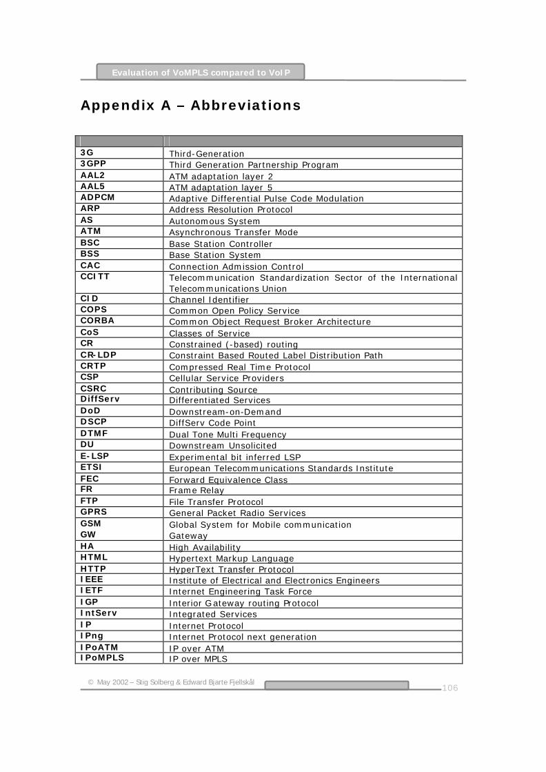
106
© May 2002 – Stig Solberg & Edward Bjarte Fjellskål
Evaluation of VoMPLS compared to VoIP
Appendix A – Abbreviations
3G Third-Generation 3GPP Third Generation Partnership Program AAL2 ATM adaptation layer 2 AAL5 ATM adaptation layer 5 ADPCM Adaptive Differential Pulse Code Modulation ARP Address Resolution Protocol AS Autonomous System ATM Asynchronous Transfer Mode BSC Base Station Controller BSS Base Station System CAC Connection Admission Control CCITT Telecommunication Standardization Sector of the International
Telecommunications Union CID Channel Identifier COPS Common Open Policy Service CORBA Common Object Request Broker Architecture CoS Classes of Service CR Constrained (-based) routing CR-LDP Constraint Based Routed Label Distribution Path CRTP Compressed Real Time Protocol CSP Cellular Service Providers CSRC Contributing Source DiffServ Differentiated Services DoD Downstream-on-Demand DSCP DiffServ Code Point DTMF Dual Tone Multi Frequency DU Downstream Unsolicited E-LSP Experimental bit inferred LSP ETSI European Telecommunications Standards Institute FEC Forward Equivalence Class FR Frame Relay FTP File Transfer Protocol GPRS General Packet Radio Services GSM Global System for Mobile communication GW Gateway HA High Availability HTML Hypertext Markup Language HTTP HyperText Transfer Protocol IEEE Institute of Electrical and Electronics Engineers IETF Internet Engineering Task Force IGP Interior Gateway routing Protocol IntServ Integrated Services IP Internet Protocol IPng Internet Protocol next generation IPoATM IP over ATM IPoMPLS IP over MPLS

107
© May 2002 – Stig Solberg & Edward Bjarte Fjellskål
Evaluation of VoMPLS compared to VoIP
IPv4 Internet Protocol version 4 IPv6 Internet Protocol version 6 IPX Internetwork Packet Exchange ISDN Integrated Services Digital Network IS-IS Intermediate System-to-Intermediate System ISO International Organization for Standardization ISP Internet Service Providers ITU International Telecommunication Union ITU-T Telecommunication Standardization Sector of the International
Telecommunications Union LAN Local Area Network LDP Label Distribution Protocol LER Label Edge Router LIB Label Information Base L-LSP Label inferred LSP LSDB Link State DataBase LSP Label Switched Path LSR Label-Switched Router ME Mobile Equipment MIPv4 Mobile Internet Protocol version 4 MIPv6 Mobile Internet Protocol version 6 MPLS Multi Protocol Label Switching MPLS-TE Multi Protocol Label Switching – Traffic Engineering MTU Maximum Transmission Unit MWIF Mobil Wireless Internet Forum NGI Next Generation Internet OAM Operations, Administration and Maintenance ORB Object Request Broker OSI Open Systems Interconnection OSPF Open Shortest Path First OSS Operational Support System PCM Pulse Code Modulation PHB Per-Hop behavior PLR Point of Local Repair POP Point-Of-Presence PoS Packet over SDH PPP Point-to-Point Protocol PSC PHB Scheduling C lass PSTN Public Switched Telephone Network QoS Quality of Service RAN Radio Access Network RFC Request For Comments RIP Routing Information Protocol RSVP Resource ReSerVation Protocol RSVP-TE Resource Reservation Protocol-Traffic Engineering RTCP Real-Time Control Protocol RTP Real-time Transport Protocol SDH Synchronous Digital Hierarchy SID Silence Information Descriptor SIGTRAN Signaling Transport SIP Session Initiation Protocol

108
© May 2002 – Stig Solberg & Edward Bjarte Fjellskål
Evaluation of VoMPLS compared to VoIP
SLA Service Level Agreement SMTP Simple Mail Transfer Protocol SNA Systems Network Architecture SONET Synchronous Optical Network SS7 Signalling System number 7 SSRC Synchronization Source TC Traffic Class TCP Transmission Control Protocol TDM Time Division Multiplexing TE Traffic Engineering ToS Type of Service UDP User Datagram Protocol UMTS Universal Mobile Telecommunications System UTRAN UMTS Terrestrial Radio Access Network VAD Voice Activity Detection VBR Variable Bit Rate VC Virtual Circuit VHE Virtual Home Environment VoATM Voice over Asynchronous Transfer Mode VoFR Voice over Frame Relay VoIP Voice over Internet Protocol VoIPoMPLS Voice over Internet Protocol over Multi Protocol Label Switching VoMPLS Voice over Multi Protocol Label Switching VoP Voice over Packet VPN Virtual Private Network

109
© May 2002 – Stig Solberg & Edward Bjarte Fjellskål
Evaluation of VoMPLS compared to VoIP
Appendix B - Glossary of Terms
Admission Control: Policy decision applied initially to QOS requests. (Should not be confused with policing, which occurs after the request is accepted and data is flowing). Behavior Aggregate: Term used to describe all the IP packets that cross a link and require the same DiffServ behavior. Class: An abstraction that can be determined by different policy criteria such as IP packet header content. Classes generally refer to a specific grouping of micro-flows, which share the same requirements for metrics like delay, jitter and packet loss. Controlled Load: Tightly approximates best-effort service under unloaded conditions. Guaranteed Service: Delay-bounded service with no queuing loss. Jitter: Refers to variations in delay. Ordered Aggregate: A set of behavior aggregates, which share an ordering constraint. Per-Hop Behavior Scheduling Class (PSC): A set of one or more per hop behaviors assigned to a group of Behavior Aggregates that comprise a given ordered aggregate. Policing: Packet-by-packet monitoring function that ensures a host does not violate its pre-established traffic characteristics. RED: Random early detection. A traffic conditioner that is used for congestion avoidance and notification that randomly drops packets in queues when congestion is detected. Weighted Fair Queuing: A flow-based queuing algorithm that does two things simultaneously: It schedules interactive traffic to the front of the queue to reduce response time, and it fairly shares the remaining bandwidth between high bandwidth flows. WFQ ensures that queues do not starve for bandwidth, and that traffic gets predictable service. [32] AS: Autonomous System. A part of the network under a single administration and usually running a single routing protocol for internal routing. BGP: Border Gateway Protocol. The Exterior Gateway Protocol used for distributing routes over the Internet backbone. CR-LDP: Constraint-based Routed Label Distribution Protocol. Extensions to LDP to set up Traffic Engineered LSPs, as defined in the Internet Draft “Constraint-based LSP Setup using LDP”.

110
© May 2002 – Stig Solberg & Edward Bjarte Fjellskål
Evaluation of VoMPLS compared to VoIP
DLCI: Data Link Circuit Identifier. The labels used in Frame Relay that are equivalent to MPLS labels. EGP: Exterior Gateway Protocol. Any routing protocol used for distributing routes between Autonomous Systems. Also the name of the first such protocol, now superseded by BGP. ER: Explicit Route. A route specified during setup and not determined by the routing protocol at each hop across the network. IGP: Interior Gateway Protocol. Any routing protocol used for distributing routes within a single Autonomous System. Labels RSVP: Extensions to RSVP to set up Traffic Engineered LSPs. LDP: Label Distribution Protocol. A protocol defined by the IETF for distributing labels to set up MPLS LSPs. LSP: Label Switched Path. A data forwarding path determined by labels attached to each data packet where the data is forwarded at each hop according to the value of the labels. LSP Tunnel: A Traffic Engineered LSP capable of carrying multiple data flows. LSR: Label Switching Router. A component of a MPLS network that forwards data based on the labels associated with each data packet. MPLS: MultiProtocol Label Switching. A standardized technology that provides connection oriented switching based on IP routing protocols and labeling of data packets. OSPF: Open Shortest Path First. A common routing protocol that provides IGP function. RSVP: Resource ReSerVation Protocol (RFC 2205). A setup protocol designed to reserve resources in an Integrated Services Internet. VoIP: Voice over IP. The process of carrying voice over an IP network. VoMPLS: Voice over MPLS. The process of carrying voice traffic over MPLS LSPs with or without using IP. VPI/VCI: Virtual Path Identifier / Virtual Channel Identifier. The labels used in ATM layer 2 networks that are equivalent to MPLS labels. VPN: Virtual Private Network. A private network provided by securely sharing resources with a wider, common network. [33]

111
© May 2002 – Stig Solberg & Edward Bjarte Fjellskål
Evaluation of VoMPLS compared to VoIP
Appendix C – References
[1] MPLS Forum, http://www.mplsforum.org/, February 2002
[2] International Telecommunication Union (ITU),
http://www.itu.int/home/index.html, February 2002
[3] IETF Multiprotocol Label Switching,
http://www.ietf.org/html.charters/mpls-charter.html, February 2002
[4] ITU-T Study Group 13,
http://www.itu.int/ITU-T/studygroups/com13/index.html, February 2002
[5] MPLS Resource Center,
http://www.mplsrc.com/about.shtml, February 2002
[6] The Information Technology Professional’s Resource Center,
http://www.itprc.com, February 2002
[7] Internet Engineering Task Force,
http://www.ietf.org, February 2002
[8] Internet2,
http://www.internet2.edu/, February 2002
[9] Internet2 Voice over IP Working Group,
http://www.internet2.edu/voip/, February 2002
[10] “Carrier Grade Voice over IP”,
Daniel Collins, Published by R.R. Donnelly & Sons Company, 2001, ISBN: 0-07-136326-2
[11] MPLS and Label Switching Networks”,
Uyless Black, Published by Prentice Hall PTR, 2001, ISBN: 0-13-015823-2

112
© May 2002 – Stig Solberg & Edward Bjarte Fjellskål
Evaluation of VoMPLS compared to VoIP
[12] “Introduction to TCP/IP - History, Architecture and Standards”, Pearson Education, http://vig.pearsoned.com/samplechapter/0130201308.pdf , January 2002
[13] “Internet Protocol”,
Search Networking.com, http://searchnetworking.techtarget.com/sDefinition/0,,sid7_gci214031,00.html, January 2002
[14] “Computer Networks – A systems approach”,
second edition, 2000, Larry L. Peterson & Bruce S. Davie, Published by Morgan Kaufman Publishers, 2000, ISBN: 1-5860-557-0
[15] “IPv6 packet header”,
Dr. Z. Huang at TELE202, http://waitaki.otago.ac.nz/telecom/tele202/handouts/ (Lecture – 12.ppt/slide 4), May 2002
[16] “TCP/IP Introduction to TCP/IP protocol”,
Tietojenkäsittelyoppi Computer Science, http://www.cs.utu.fi/ajarvi/IpSec-I.pdf, May 2002
[17] “IPv6”,
searchWebManagement.com, http://searchwebmanagement.techtarget.com/sDefinition/0,,sid27_gci212389,00.html, January 2002
[18] “Mobility in IPv6” – Graduate Thesis,
Jørn Hunskaar & Trond Almar Lunde, Agder University College, http://siving.hia.no/ikt01/ikt6400/talund99/Mobility_in_IPv6_final_release.doc, January 2002
[19] “User Datagram Protocol”,
J. Postel, IETF RFC 768, http://www.ietf.org/rfc/rfc0768.txt?number=768, 28. August 1980
[20] “Connectionless Transport: UDP”,
Computer Networks Research Group, http://www-net.cs.umass.edu/kurose/transport/UDP.html, February 2002
[21] RTP/RTCP,
“VoIP, The Basic”, http://www.sidkhosla.com/papers/voip.doc, March 2002

113
© May 2002 – Stig Solberg & Edward Bjarte Fjellskål
Evaluation of VoMPLS compared to VoIP
[22] “Effnet: CRTP”,
Effnet, http://www.effnet.com/sites/effnet/content/eng/whitepapers/Solutions_Toolkit_-_CRTP.pdf, March 2002
[23] “Compressing IP/UDP/RTP Headers for Low-Speed Serial Links”,
S. Casner & V. Jacobson, IETF RFC 2508, http://www.ietf.org/rfc/rfc2508.txt?number=2508, February 1999
[24] “Algorithm cuts VoIP bandwidth requirement”,
EETimes, http://www.eetimes.com/story/OEG20020108S0054, March 2002
[26] “Session Initiation Protocol”,
search Netvorking.com, http://searchnetworking.techtarget.com/sDefinition/0,,sid7_gci541639,00.html, March 2002
[25] “SIP: Session Initiation Protocol”,
Handley, Schulzrinne, Schooler, Rosenberg, http://www.ietf.org/rfc/rfc2508.txt?number=2543, March 1999
[27] “H.323”,
search Networking.com, http://searchnetworking.techtarget.com/sDefinition/0,,sid7_gci516602,00.html, March 2002
[28] “QoS”,
search Networking.com, http://searchnetworking.techtarget.com/sDefinition/0,,sid7_gci213826,00.html, March 2002
[29] “QoS for real-time IP traffic”,
Helge Gundersen & Frode Trydal, Agder University College, http://siving.hia.no/ikt01/ikt6400/ftryda95/Report.doc, March 2002
[30] “Protection and Restoration in MPLS Networks”,
DATA Connection, http://www.dataconnection.com/download/mplsprotwp2.pdf, February 2002
[31] “TCP/IP - Internet Protocol”,
Nortel Networks, http://www.nortelnetworks.com/products/library/collateral/data_tech_handbook_2.pdf ,

114
© May 2002 – Stig Solberg & Edward Bjarte Fjellskål
Evaluation of VoMPLS compared to VoIP
February 2002 [32] “Multiprotocol Label Switching”,
Search Networking.com, http://searchnetworking.techtarget.com/sDefinition/0,,sid7_gci214350,00.html, February 2002
[33] MPLS Forum,
http://www.mplsforum.org/, February 2002
[34] “Voice over MPLS – Bearer Transport Implementation Agreement”,
MPLS Forum, http://www.mplsforum.org/VoMPLS_IA.pdf , February 2002
[35] ”Delivering Internet Quality of Service”,
Avici Systems, http://www.avici.com/technology/whitepapers/qos-2-00.pdf , March 2002
[36] “MPLS Traffic Engineering: A Choice of Signalling Protocols”,
Data Connection, http://www.dataconnection.com/download/crldprsvp.pdf , March 2002
[37] “MPLS and label switching networks”,
Uyless Black, ISBN 0-13-015823-2, 2001
[38] “Engineering traffic in MPLS networks”,
EETimes, http://www.eetimes.com/story/OEG20011121S0066, April 2002
[39] “Traffic Engineering With Multiprotocol Label Switching”,
Avici Systems, http://www.avici.com/technology/whitepapers/mpls_wp.pdf , April 2002
[40] “Label-Switching Technique Helps Transmit Voice over IP Networks”,
Ben Miller, http://www.integralaccess.com/pdf/vompls.pdf , March 2002
[41] “Voice Quality (VQ) in Converging Telephony and Internet Protocol (IP)
Networks”, International Engineering Consortium, http://www.iec.org/online/tutorials/voice_qual/index.html, May 2002

115
© May 2002 – Stig Solberg & Edward Bjarte Fjellskål
Evaluation of VoMPLS compared to VoIP
[42] “MPLS – Technology and Application”,
The School of Engineering Science, http://www.ensc.sfu.ca/~ljilja/cnl/presentations/william/mpls/sld023.htm, April 2002
[43] “Fulfilling The Promise of MPLS: Ethernet Private Line Services Emerge as a
First Killer App”, Stephen Vogelsang, Converge! Network Digest, http://www.convergedigest.com/Bandwidth/archive/010806GUEST-stephenvogelsgang1.htm, April 2002
[44] “Product Bulletin”,
WiLan, http://www.wi-lan.com/support/upgrades/sw_bulletin_12024-58_3-1.pdf , April 2002
[45] “Market View”,
Telica, http://www.telica.com/about/market.shtml, April 2002
[46] “Multiprotocol Label Switching (MPLS)”,
The Technology Guide Series, http://www.itpapers.com/techguide/mpls.pdf , April 2002
[47] ”UMTS”,
search Networking.com, http://searchnetworking.techtarget.com/sDefinition/0,,sid7_gci213688,00.html, May 2002
[48] “UMTS Network”,
UMTS world, http://www.umtsworld.com/technology/system.htm, May 2002
[49] ”TCP/IP – Internet Protocol”,
Nortel Networks, http://www.nortelnetworks.com/products/library/collateral/data_tech_handbook_2.pdf , May 2002
[50] “GSM evolution to 3G: Best Value Best Performance”,
Dr. J.T. Bergquist, http://media.corporate-ir.net/media_files/nys/nok/video/bergqvist.pdf, May 2002
[51] ”A survey of mobile Internet wireless technologies”,
CS222 - Glenn L. Cserey 03/19/01, http://www.cs.ucsd.edu/classes/wi01/cse222/projects/reports/mobile-wireless-16.ps, May 2002

116
© May 2002 – Stig Solberg & Edward Bjarte Fjellskål
Evaluation of VoMPLS compared to VoIP
[52] “ATM and UMTS/Wireless Applications Interworking”,
The ATM Forum, http://www.atmforum.com/pages/interworksw/wireless.html, May 2002
[53] “MPLS for Wireless Network Evolution”,
Nortel Networks, http://www.nortelnetworks.com/products/library/collateral/mpls_wirelesswp.pdf , May 2002