
Evaluation of Seismic Behavior of Circuit Breaker Based · PDF fileEvaluation of Seismic...
8
Research Journal of Recent Sc Vol. 4(3), 121-128, March (201 International Science Congress Associatio Evaluation of Seismic Beh Dept. of Civil E Avai Received 19 th M Abstract Electrical Network as one of the main life Among the various components of Electric substations have important consideration, transmission and distribution of the netwo evaluation of the seismic power substation assess the vulnerability and seismic behav of the value of seismic vulnerability of stru fragility curves is to create a relation be breaker as one of the most widely used equ Keywords: Lifeline, power substation, fra Introduction History of Electric Power: Benjamin Frankli discovery of electricity. Born in 1706, he electricity in the early 1750s. His observati kite experiment, verified the nature of electric and 1850 there were many great discoveries i electricity and magnetism by Volta, Coulom Faraday, and others. It was found that electri a magnetic field and that a moving magne electricity in a wire. This led to many inven battery (1800), generator (1831), electri telegraph (1837), and telephone (1876), intriguing inventions. In 1879, Thomas Ediso efficient light bulb, similar to those in use t placed into operation the historic Pearl Str plant and the first direct current (dc) distributi York City, powering over 10,000 electric light Power Substation: In order to reduce the losses of the power transmission lines, am decreased and voltage must be increase distribution and consumption of electrical po the voltage to make it possible for consumers Substation is named on collection equipm electromechanical that connects the multi-in the multi-output electrically and operations care, conversions, monitor and control the done 1,2 (figure-1) ciences _________________________________________ 15) on ehavior of Circuit Breaker Based o Approach Hassani M., Safi M. and Hassani N. Engineering, Shahid Beheshti University, Tehran, IRAN ilable online at: www.isca.in, www.isca.me March 2014, revised 8 th June 2014, accepted 29 th October 2014 eline plays vital role in the economic, social and politic cal Network, such as power plants, substations and transm , and Play a vital role in network. So if for any reason ork happens, it may cause irreparable damage. So this s n as an important part of Electrical Network. One of the vior of power substation is to use the fragility curves. In th uctures proportion with the seismic parameters will be exp etween a failure criterion and a criterion of magnitude uipment in power substation will be study and fragility cur agility curves, seismic evaluation, crisis management. in is known for his he began studying ions, including his city. Between 1750 in the principles of mb, Gauss, Henry, ic current produces etic field produces ntions such as the ic motor (1831), plus many other on invented a more today. In 1882, he reet steam–electric ion system in New htbulbs 1 . electricity energy mperage must be ed. Similarly, in ower should reduce s to use electricity. ment, electrical or nput electrically to such as maintain, switching will be Figure- System over The main task of post is switching the combination of two modes are s post is taking over the power fro delivers it to the Distribution Sy aspects of consumers connected network is not cost efficient. So isolating each of the distribution n happens by errors occurring in the o Behavior of Substations in Earthq of equipment seismic vulnerabili similar structures during past ea checked, as a starting point perfec desired. Equipment such as p _________ ISSN 2277-2502 Res.J.Recent Sci. 121 on Probabilistic cal relations of a country. mission lines, high voltage n disorder happens on the study is going through the most effective methods to his method, the evaluation pressed. In fact, the aim of e. In this study the circuit rves will be drawn for it. -1 rview voltage, in many substations seen. The task of distribution om transmission system and ystem. Economic and safety directly to the transmission o the task of substation is networks or transmission that other. quake: About the assessment ity, the injury studies and arthquakes will always be ctly reasonable and logical is power transformer, current
-
Upload
truongdung -
Category
Documents
-
view
226 -
download
3
Transcript of Evaluation of Seismic Behavior of Circuit Breaker Based · PDF fileEvaluation of Seismic...

Research Journal of Recent Sciences
Vol. 4(3), 121-128, March (201
International Science Congress Association
Evaluation of Seismic Behavior of Circuit Breaker
Dept. of Civil Engineering, Shahid Beheshti University, Tehran, IRAN
Available online at: Received 19th March
Abstract
Electrical Network as one of the main lifeline plays vital role in the economic, social and political relations of a country.
Among the various components of Electrical Network, such as power plants, substations and transmission lines, high voltage
substations have important consideration, and Play a vital role in network. So if for any reason disorder happens on the
transmission and distribution of the network happens, it may cause irreparable damage. So this study is going through the
evaluation of the seismic power substation as an important part of Electrical Network.
assess the vulnerability and seismic behavior of power substation is to use the fragility curves. In this method, the evaluat
of the value of seismic vulnerability of structures proportion with the seismic parameters will be expressed. In fact, the aim of
fragility curves is to create a relation between a failure criterion and a criterion of magnitude. In this study the circuit
breaker as one of the most widely used equipment in power substation will be study and fragility curves will be drawn for it.
Keywords: Lifeline, power substation, fragility curves, seismic evaluation, crisis management.
Introduction
History of Electric Power: Benjamin Franklin is known for his
discovery of electricity. Born in 1706, he
electricity in the early 1750s. His observations, including
kite experiment, verified the nature of electricity. Betwee
and 1850 there were many great discoveries in the principles
electricity and magnetism by Volta, Coulomb, Gauss, Henry,
Faraday, and others. It was found that electric current produces
a magnetic field and that a moving magnetic field produces
electricity in a wire. This led to many inventions such as the
battery (1800), generator (1831), electric motor
telegraph (1837), and telephone (1876), plus many other
intriguing inventions. In 1879, Thomas Edison invented a more
efficient light bulb, similar to those in use today. In 1882, he
placed into operation the historic Pearl Street steam
plant and the first direct current (dc) distribution system in
York City, powering over 10,000 electric lightbulbs
Power Substation: In order to reduce the electricity energy
losses of the power transmission lines, amperage must be
decreased and voltage must be increased
distribution and consumption of electrical power should reduce
the voltage to make it possible for consumers t
Substation is named on collection equipment, electrical or
electromechanical that connects the multi-input electrically to
the multi-output electrically and operations such as maintain,
care, conversions, monitor and control the switchi
done1,2
(figure-1)
Sciences __________________________________________
(2015)
International Science Congress Association
Evaluation of Seismic Behavior of Circuit Breaker Based on Probabilistic
Approach
Hassani M., Safi M. and Hassani N.
Dept. of Civil Engineering, Shahid Beheshti University, Tehran, IRAN
Available online at: www.isca.in, www.isca.me March 2014, revised 8th June 2014, accepted 29th October 2014
Electrical Network as one of the main lifeline plays vital role in the economic, social and political relations of a country.
Among the various components of Electrical Network, such as power plants, substations and transmission lines, high voltage
ions have important consideration, and Play a vital role in network. So if for any reason disorder happens on the
transmission and distribution of the network happens, it may cause irreparable damage. So this study is going through the
ismic power substation as an important part of Electrical Network. One of the most effective methods to
assess the vulnerability and seismic behavior of power substation is to use the fragility curves. In this method, the evaluat
vulnerability of structures proportion with the seismic parameters will be expressed. In fact, the aim of
fragility curves is to create a relation between a failure criterion and a criterion of magnitude. In this study the circuit
st widely used equipment in power substation will be study and fragility curves will be drawn for it.
Lifeline, power substation, fragility curves, seismic evaluation, crisis management.
Benjamin Franklin is known for his
, he began studying
electricity in the early 1750s. His observations, including his
kite experiment, verified the nature of electricity. Between 1750
and 1850 there were many great discoveries in the principles of
electricity and magnetism by Volta, Coulomb, Gauss, Henry,
and others. It was found that electric current produces
and that a moving magnetic field produces
many inventions such as the
battery (1800), generator (1831), electric motor (1831),
telegraph (1837), and telephone (1876), plus many other
. In 1879, Thomas Edison invented a more
in use today. In 1882, he
Street steam–electric
plant and the first direct current (dc) distribution system in New
York City, powering over 10,000 electric lightbulbs1.
to reduce the electricity energy
of the power transmission lines, amperage must be
decreased and voltage must be increased. Similarly, in
distribution and consumption of electrical power should reduce
the voltage to make it possible for consumers to use electricity.
collection equipment, electrical or
input electrically to
output electrically and operations such as maintain,
care, conversions, monitor and control the switching will be
Figure-
System overview
The main task of post is switching voltage, in many substations
the combination of two modes are seen. The task of distribution
post is taking over the power from transmission system and
delivers it to the Distribution System. Economic and safety
aspects of consumers connected directly to the transmission
network is not cost efficient. So the task of substation is
isolating each of the distribution networks or transmission that
happens by errors occurring in the other.
Behavior of Substations in Earthquake:
of equipment seismic vulnerability, the injury studies and
similar structures during past earthquakes will always be
checked, as a starting point perfectly reasonable and lo
desired. Equipment such as power transformer, current
_____________ ISSN 2277-2502
Res.J.Recent Sci.
121
Based on Probabilistic
Electrical Network as one of the main lifeline plays vital role in the economic, social and political relations of a country.
Among the various components of Electrical Network, such as power plants, substations and transmission lines, high voltage
ions have important consideration, and Play a vital role in network. So if for any reason disorder happens on the
transmission and distribution of the network happens, it may cause irreparable damage. So this study is going through the
One of the most effective methods to
assess the vulnerability and seismic behavior of power substation is to use the fragility curves. In this method, the evaluation
vulnerability of structures proportion with the seismic parameters will be expressed. In fact, the aim of
fragility curves is to create a relation between a failure criterion and a criterion of magnitude. In this study the circuit
st widely used equipment in power substation will be study and fragility curves will be drawn for it.
-1
System overview
task of post is switching voltage, in many substations
the combination of two modes are seen. The task of distribution
post is taking over the power from transmission system and
it to the Distribution System. Economic and safety
aspects of consumers connected directly to the transmission
network is not cost efficient. So the task of substation is
isolating each of the distribution networks or transmission that
curring in the other.
Behavior of Substations in Earthquake: About the assessment
of equipment seismic vulnerability, the injury studies and
similar structures during past earthquakes will always be
checked, as a starting point perfectly reasonable and logical is
Equipment such as power transformer, current

Research Journal of Recent Sciences _____________________________________________________________ ISSN 2277-2502
Vol. 4(3), 121-128, March (2015) Res.J.Recent Sci
International Science Congress Association 122
transformer, and the circuit breaker, is fixed components and
critical component of every single process. Previous evidence
suggests that the failure rate of theses equipment have a direct
connection with operating voltage, and Failure patterns each of
them is nearly equal2,3
.
Investigate the effects of the earthquake occurred, is shown that
the whole reason for the high vulnerability of substation
equipment is as follows: The use of brittle materials in the core
and critical part of equipment (including ceramic materials).
Inadequate lateral strength and stiffness. Low levels of
equipment damping, interactions between adjacent equipment,
interactions with the internal components of equipment,
excessive equipment load, Inadequate and irregular distribution
of load on height, inappropriate installation and maintenance.
The fragility curves: To achieve good vision in relation
Seismic behavior of substation, fragility curves will be drawn.
In fact the fragility curve is a useful tool in order to estimate the
seismic vulnerability of substation, which could positively result
as3: Fragility curves are used for comparison of seismic
modification techniques. Since time management, determine the
process in the relief and rescue Emergency Incident, Fragility
curves can be a useful tool to estimate the amount of damage to
substation and to determine the requirements of a post after
damage. Development of fragility curves can be used to assess
the seismic vulnerability substation injury scenario to provide
better guidance for operational teams in emergency cases. Also
these curves can use to order the parts and equipment in the
manufacturing sector. That is the appropriate parameters to
verify the quality and acceptance criteria of specified
equipment.
Theory of fragility curves: Fragility curves Indicates the
conditional probability of reaching or passing of a damage index
against the Ground motion intensity. In order to express the
damage of structural or non-structural vulnerability of the
various components in terms of earthquake risk probability of
passing of certain in terms of a known earthquake
characteristics such as PGA, PGV, PGD can be expressed.
Repeat this function for different values of PGA with another
single-parameter to produce a normal curve called fragility
curves. Fragility curve can be defined both as a component or
set of components and system. Fragility curve can use to
compare different techniques for correcting seismic and seismic
design of structures and improvements. In general, the
vulnerability curves of equation-1 can be represented2,5
.
Figure-2
Photos of 230 kV Post
Figure-3
Damage to high voltage equipment in Caopo Power Plant in the 2008 Wenchuan, China earthquake (China Earthquake
Administration, 2008)4

Research Journal of Recent Sciences _____________________________________________________________ ISSN 2277-2502
Vol. 4(3), 121-128, March (2015) Res.J.Recent Sci
International Science Congress Association 123
( ) ( )imIMdDPimF ii =≥= (1)
In this formula Fi (im) is the possibility of reaching or passing
damage (D), of the damage index (di) in the intensity ground
motion (IM) expresses. In the basic theory of reliability,
vulnerability only probabilistic cumulative distribution function
(CDF) is to work, to determine the function of only two
parameters, the mean and the standard deviation is required. A
vulnerability curve according to equation-2 has the analytical
form6:
( )
=
β
a/MLnΦPf
(2)
This formula Pf is potential vulnerability, ø is the standard
normal cumulative distribution function (Gaussian), a maximum
ground acceleration given (PGA), M is Average of
accelerations, ß is the logarithmic standard deviation. You can
replace whit maximum ground acceleration (PGA) of peak
ground velocity (PGV) and spectral displacement (SD).
Log-normal distribution: If the function y as a function of the
variable x: logarithm Y = Ln (x), then we say that the variable x
has a normal distribution. Probability density function of a
normally distributed variable is defined in equation-3:
( )( )( )( ) ( )
( )0σm,θ,x
2πσθx
exf
222σi/mθxln
>≥−
=
−−
(3)
In this formula σ is the shape parameter, and Υ is the location
parameter, m is the magnification parameter, When m=1
andΥ=0 the standard logarithmic distribution is called. When
Υ=0 it is called two-parameter logarithmic normal distribution.
Standard logarithmic distribution function is defined as a
relation-4:
( )( )( )( ) ( )
2 2- ln x-θ /m i 2σ1f x = e x³θ,m,σ>0
xσ 2π (4)
Since the general form of probability functions can be expressed
in terms of standard distribution sentences, formulas are given
for the standard form. In previous figure, for four values of the
probability density function in the form of a log-normal
distribution is plotted. There are several typical parameters for a
normal distribution, the form of which was used in this study, is
given below. The basic theory of reliability, vulnerability, only
the cumulative probability function (CDF) is to work.
Cumulative distribution function: Formulation of the
cumulative distribution function of the normal distribution
logarithmic is equation-5.
( )( )
0σ,θxσ
x1nΦxf >≥
=
(5)
In this formula ø is the cumulative distribution function of the
normal distribution. In the figure below, the log-normal
cumulative distribution function similar σσσσ values, as in figure 4
was used, is drawn.
Logarithmic normal distributions (two parameters) have at least
three fundamental roles in human and ecological risk
assessments: First, many of the functions of the physical,
chemical, biological and statistical are tended to generate
random variables that follow a normal logarithmic distribution.
First, many of the functions of the physical, chemical, biological
and statistical are tended to generate random variables that
follow a normal logarithmic distribution. Next when the
conditions of the central limit theory is obtained Mathematical
methods for multiplying a series of random variables, will create
a new random variable (product), regardless the distribution of
input variables. The tendency (in effect limit applies) having a
logarithmic characteristic is normal. Third, the normal
distributions are able to be reproduced using multiplication and
division. It is most reasonable that the resulted error will
consider as independent small errors. It can be used with the
central limit theory. This theory states that the distribution of a
large number of independent random variables follows
approximately a normal distribution.
Figure-4
Probability density functions of the log-normal distribution
for the four mean values of 0.5, 1
0
0.05
0.1
0.15
0.2
0.25
0.3
0.35
0.4
0.45
0 1 2 3 4 5 6
pro
bab
ilit
y d
ensi
ty
x
Lognormal PDF(Sigma=0.5)
0
0.05
0.1
0.15
0.2
0.25
0.3
0 1 2 3 4 5 6
pro
bab
ilit
y d
ensi
ty
x
Lognormal PDF(Sigma=1)

Research Journal of Recent Sciences _____________________________________________________________ ISSN 2277-2502
Vol. 4(3), 121-128, March (2015) Res.J.Recent Sci
International Science Congress Association 124
Figure-5
Log-normal cumulative distribution functions for four mean
values of 0.5, 1
Modeling and Seismic Analysis: The circuit breaker can be
mounted on the various types of structures, and various bases
will have different effects. This section examines the seismic
behavior of circuit breaker singular and without regard to base
effects. Materials used in the construction of this equipment are
Ceramics and composite that ceramic part is for its insulating
and flanges are made of aluminum. Geometrical characteristics
and material properties are listed in the following tables.The
circuit breaker in this study is producing in Iran Switch
Company, and structural detail that used are according to
companies detail2,7,8
.
Table-1
Materials and Height of the Equipment Components
Height (mm) Material Part Name
1320 Ceramic Bot Porcelain
2403 Ceramic Top Porcelain
variable Aluminum Flanges (Bot and Top)
Table-2
Materials Properties2, 7
Density
)(3
mm
tonne
Poisson’s Ratio
Young Modulus
)(2
mm
N
Material
2.0 E -9 0.24 72400 Aluminum
2.65 E -9 0.23 70000 Porcelain
In this section, the fragility curves based on the description
given in the previous section are given. Fragility curves
obtained in this study are based on time history analysis. The
process of doing so is that: after modeling, analysis was
performed by finite element method. Then using the results of
FEM analysis fragility curves were drawn.
Modal Analysis: Before performing dynamic time history
analysis, modal analysis method was used to compare the results
with values in the literature and should be verified. The modal
analysis results are given in the following table. This result
verified by literature review in reference-2.
Table-3
Modal analysis results
Modal analysis (Frequency)
Mode -4 Mode -3 Mode -2 Mode -1
68.6 68.5 9.11 9.05
Records used in the analysis: In the following table, the used
records in the time history analysis are given. As it can be seen,
in some cases there is a record of an earthquake or two. There
records are two components and then the records number are 35
and generally there are 70 time history of acceleration that used
after correction in the analysis.
Figure-6
Geometry of Top Porcelain (Left is from Modeling and right
is from Company)
0
0.2
0.4
0.6
0.8
1
0 1 2 3 4 5 6
pro
bab
ilit
y
x
Lognormal CDF(Sigma=0.5)
0
0.1
0.2
0.3
0.4
0.5
0.6
0.7
0.8
0 1 2 3 4 5 6
pro
bab
ilit
y
x
Lognormal CDF(Sigma=1)

Research Journal of Recent Sciences _____________________________________________________________ ISSN 2277-2502
Vol. 4(3), 121-128, March (2015) Res.J.Recent Sci
International Science Congress Association 125
Figure-7
Geometry of Circuit Breaker Mounted on Rigid Base
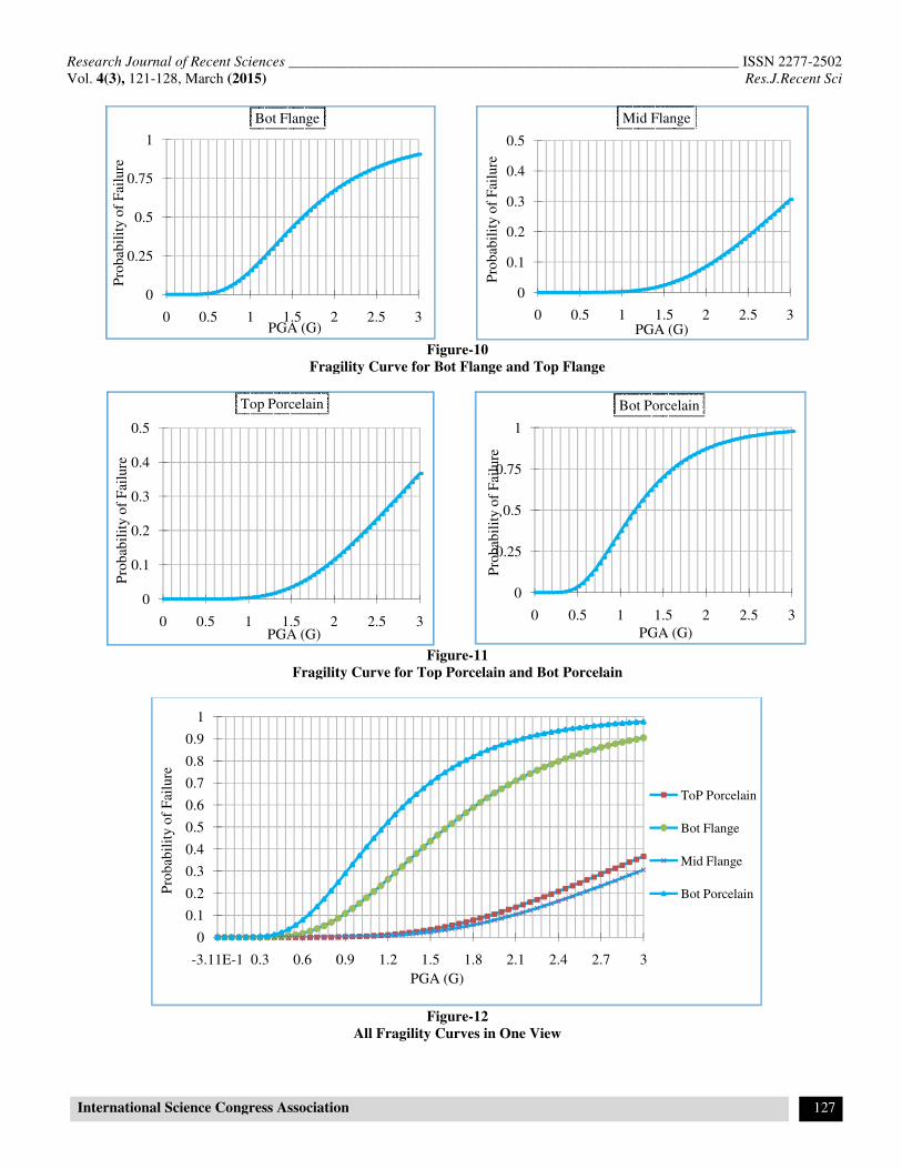
Fragility Curves for Circuit Breaker (CB): Failure Modes in the first case, damage of the equipment, are described as the ceramic cracking or failure of the ceramic units due to a high stress. According to the experiences of past earthquakes, a ceramic unit can be broken into two modes as follows: tensile failure, compressive failure
9,10.
Due to axial force or bending moment stresses in ceramic or combined effect of greater tolerance values and ultimately lead to failure. Ceramic composition and structure of each manufacturer is different and therefore the resistance will vary. However, resistance of insulators and bushings are strongly influenced by the type of the end connections. End connection that is designed improperly can actually create stress concentrations in a narrow band or in a spot, reduce insulation resistance. It should also be noted that the stress concentration in a narrow band or in a spot, reduces the resistance of insulators. It should also be noted that the ceramic materials resistant to stretching are several degrees of pressure. Some studies based on several catalogs and guide the company's Japanese Electric Factory JEAG-5003 (1999) authorized the tensile and compressive stresses, respectively 40 Mpa, 24 MP Compressive stress on the contact surface between cross are a function of ceramics and anchor flange . Due to the limitations in different editions to determine the allowable stress suppose 40Mpa in this study. Accordance to the regulations of the 1984 edition of IEEE, the maximum allowable stress for a cross made of porcelain can be between 25 to 50 % of its maximum tension. Accordance to the
regulations of the 1997 and 2005 edition of IEEE, the
maximum allowable stress for porcelain can be 50 % of its maximum tension .in this study the fragility curves derived from the 25% strength ceramic and other members of number 40 Mpa is used. In the second case, yielding of aluminum flanges has been considered. Allowable stress considered for of aluminum is 100Mpa
2,10.
Fragility curves for each case are given below. As can be seen in the following figures, probability of failure of bottom porcelain is most. After it, after that, bottom flange is in second place. Top porcelain and middle flange are in 3th and 4th place, respectively.
Figure-8
Mode Shapes
Table-4

Research Journal of Recent Sciences _____________________________________________________________ ISSN 2277-2502
Vol. 4(3), 121-128, March (2015) Res.J.Recent Sci
International Science Congress Association 126
List of record used in the dynamic analysis
Vs30
(m/s)
Distance
(km) M Station Year No Event
337 36 6.1 Bandar-e-Abbas 1975 Bandar-e-Abbas 1
564 55 7.4 Boshrooyeh
645 54 7.4 Tabas 1978 Tabas 2
539 15 6 Talesh 1978 Tularud (Gilan) 3
701 75 7.1 Khezri 1979 Qaen(Khorasan(south)) 4
529 93 7.1 Gonabad
365 13 7 Golbaf 1981 Golbaft 5
456 94 7.4 Qazvin
291 101 7.4 Abhar 1990 Manjil-roodbar 6
291 41 7.4 Ab-bar
589 48 6 Kariq 1997 Eslamabad(Ardebil) 7
613 62 6.5 Kaboodar Ahang 2002 Avaj 8
314 35 6.5 Razan
339 42 6.3 Hasan Keyf 2004 Kajoor,Firooz abad 9
490 99 6.3 Moalem Kelayeh
341 14 6.1 Agh Gala 2005 Enchehborun 10
226 16 6.4 Zarand 2005 Zarand 11
316 65 6.6 Meteoroloji İstasyon 1983 ERZURUM 12
263 48 6.2 Tarım Ice 1998 ADANA 13
366 65 6.2 Meteoroloji İstasyon
348 81 7.4 Devlet Hastanesi
1999 KOCAELI 14 282 101 7.4 Meteoroloji İstasyon Merkezi
701 43 7.4 Marmara Araştırma Merkezi
294 36 7.1 Bayındırlık ve İskan 1999 DUZCE 15
529 12 6.3 Bayindirlik ve iskan Mudurlugu 2003 BINGOL 16
356 13 6.7 Beverly Hills
309 27 6.7 Canyon country - WLost cany 1994 Northridge 17
425 20 6.5 Tolmezzo 1976 Friuli 18
316 40 6.6 La-Holly wood Stror FF 1971 San Fernando 19
275 34 6.5 Delta 1979 Imperial Valley 20
354 86 7.3 Yermo Fire Station 1992 Landers 21
199 47 6.9 Hollister City Hall Annex 1989 Loma Prieta 22
299 43 7.0 Heathcote Valley Primary Schoo
2010 New Zealand 23
259 32 7.6 Chi-Chi-CHY101 1999 Chi-Chi 24
701 76 7.6 Chi-Chi-TCU045
Figure-9
SomeAcceleration Time History Used in Analysis
-0.15
-0.1
-0.05
0
0.05
0.1
0.15
0 20 40
a(g)
t(s)
bandar-e-abbas
-1
-0.5
0
0.5
1
0 20 40
a (g
)
t(s)
tabas
Research Journal of Recent Sciences ____________________________________
Vol. 4(3), 121-128, March (2015)
International Science Congress Association
Fragility Curve for Bot Flange
Fragility Curve for Top Porcelain
0
0.25
0.5
0.75
1
0 0.5 1 1.5 2
Pro
bab
ilit
y o
f F
ailu
re
PGA (G)
Bot Flange
0
0.1
0.2
0.3
0.4
0.5
0 0.5 1 1.5 2
Pro
bab
ilit
y o
f F
ailu
re
PGA (G)
Top Porcelain
0
0.1
0.2
0.3
0.4
0.5
0.6
0.7
0.8
0.9
1
-3.11E-1 0.3 0.6 0.9
Pro
bab
ilit
y o
f F
ailu
re
_______________________________________________________
International Science Congress Association
Figure-10
Fragility Curve for Bot Flange and Top Flange
Figure-11
Fragility Curve for Top Porcelain and Bot Porcelain
Figure-12
All Fragility Curves in One View
2 2.5 3
0
0.1
0.2
0.3
0.4
0.5
0 0.5 1 1.5
Pro
bab
ilit
y o
f F
ailu
re
PGA (G)
Mid Flange
2 2.5 3
0
0.25
0.5
0.75
1
0 0.5 1 1.5
Pro
bab
ilit
y o
f F
ailu
re
PGA (G)
Bot Porcelain
0.9 1.2 1.5 1.8 2.1 2.4 2.7 3
PGA (G)
_______________ ISSN 2277-2502
Res.J.Recent Sci
127
2 2.5 3PGA (G)
Mid Flange
2 2.5 3
PGA (G)
Bot Porcelain
ToP Porcelain
Bot Flange
Mid Flange
Bot Porcelain

Research Journal of Recent Sciences _____________________________________________________________ ISSN 2277-2502
Vol. 4(3), 121-128, March (2015) Res.J.Recent Sci
International Science Congress Association 128
Conclusion
Since circuit breaker (CB) is widely used in power station, in
this paper seismic behavior of it was discussed. Because of the
effect of the various bases on the seismic performance of CB,
The basic effect is not considered here and CB considered
singular. Geometry of CB was modeled and dynamic analysis
was done, after this, fragility curves were drowned. As seen
figure-11, the Product has high reliability in earthquake and in
PGA=1g, Probability of failure is about 0.3. Among any part of
circuit breaker, bot porcelain has most failure probability and
mid flange has least.
Reference
1. Blume Steven W, Electrical Power System Basics for
the Nonelectrical Professional., S.l.: John wiley and
Sons, Inc., (2007)
2. Hassani Meisam., Determining Fragility Curve Whit
Probabilistic Method and Reliability for Selected Power
Substation., MSc Thesis, Shahid Beheshti University,
Iran, (2014)
3. Karami Mohammadi, Reza Nickfar and V. Ekrami.,
Seismic Design of Transmission Posts., Publicated at
Khaje Nasireddin Toosi University, In Persian, Iran,
(2012)
4. Bastami Morteza et al., Proposed Input Waves for
Seismic, Design of Power Substation Equipment, 15th
WCEE conference, LISBOA, (2012)
5. David Bur Master, Using lognormal distributions and
lognormal probability plots in probabilistic risk
assessments, Human and Ecological Risk Assessment An
International Journal, 05, (1997)
6. Yoshiharu Shumuta, Damage of Electric Power facilities
in Tohoku Electric Power Co., Inc, Central Research
Institute of electric Power Industry Civil Engineering
Lab., Tohoku Chiho-Taiheiyo- Oki Earthquake., (2011)
7. IEEESTD 693, IEEE Recommended Practice for Seismic
Design of Substations, 3Park Avenue, New York, NY
10016-5997, USA: Substations Committee of IEEE
Power Engineering Society, (2006)
8. Japan Electric Association, (JEA., Earthquake Resistant
Design Guideline for Electric Facilities in Power
Substation. JEAG 5003-1999, Japan, (in Japanese),
(1999)
9. Khalvati A.H., Hosseini M. and Mohammadpour S.,
Seismic Behavior of 63kV and 132KvSubstation Post
Insulators with Flexible Conductors, an Experimental
Approach, Journal of Seismology and Earthquake
Engineering, 13(2), (2011)
10. Bastami M, Seismic Reliability of Power Supply System
Based on Probabilistic Approach, PhD Thesis, Kobe
University, Japan, (2007)