Evaluation of Mechanical Properties and Microstructure for...
10
Evaluation of Mechanical Properties and Microstructure for Laser Deposition Process and Welding Process Yaxin Bao 1 , Jianzhong Ruan 1 , Todd E. Sparks 1 , Jambunathan Anand 2 , Joseph Newkirk 2 , Frank Liou 1 1 Mechanical Engineering, University of Missouri-Rolla 2 Material Science & Engineering, University of Missouri-Rolla Abstract Laser Aided Manufacturing Process (LAMP) can be applied to repair steel die/molds which are currently repaired using traditional welding process in industry. In order to fully understand the advantages of laser deposition repair process over traditional welded-repair process, the mechanical properties such as tensile strength and hardness of H13 tool steel samples produced by these two processes were investigated. The microstructure and fracture surface of the samples were analyzed using optical microscope and SEM (Scanning Electron Microscope). Moreover, depositions on substrates with different shapes were studied to evaluate the performance of LAMP on damaged parts with complicated geometric shape. Keywords: Laser deposition, Microstructure, H13 tool steel, Repair Introduction A laser-based die repair system [1] is being developed in the Laser Aided Manufacturing Process (LAMP) lab of University of Missouri-Rolla. For die casting, the primary failure mechanism of steel molds is abrasive wear [2]. If a repaired die can provide a similar life to a new one, then it is much more cost-effective to repair it than manufacturing a new die. Currently, the most common used repair process in industry is fusion welding. However, welding has some significant disadvantages, such as the randomicity of manual process which affects the reliability and quality of the repair very much. On the other hand, the LAMP system automatically complete the repair process with the hybrid laser metal deposition and machining process, and thus, the performance of the repaired part is reliable. This paper concentrates on characterizing laser deposition process compared to the TIG welding. The same substrates were separated into two groups, one group was TIG welded, the other laser deposited. Tensile tests and hardness tests [3] were performed. A fracture analysis and microstructure comparisons were conducted on the samples after mechanical testing. Due to the faster cooling rate, the average hardness of deposited samples is higher than that of welded samples. The fracture surface analysis shows that the deposited samples retain some ductility, indicating that the hardness can be improved via heat treatment. Reviewed, accepted September 14, 2006 280
Transcript of Evaluation of Mechanical Properties and Microstructure for...
Evaluation of Mechanical Properties and Microstructure for Laser Deposition Process and Welding Process
Yaxin Bao1, Jianzhong Ruan1, Todd E. Sparks1, Jambunathan Anand2, Joseph Newkirk2,Frank Liou1
1Mechanical Engineering, University of Missouri-Rolla 2Material Science & Engineering, University of Missouri-Rolla
Abstract
Laser Aided Manufacturing Process (LAMP) can be applied to repair steel die/molds which are currently repaired using traditional welding process in industry. In order to fully understand the advantages of laser deposition repair process over traditional welded-repair process, the mechanical properties such as tensile strength and hardness of H13 tool steel samples produced by these two processes were investigated. The microstructure and fracture surface of the samples were analyzed using optical microscope and SEM (Scanning Electron Microscope). Moreover, depositions on substrates with different shapes were studied to evaluate the performance of LAMP on damaged parts with complicated geometric shape.
Keywords: Laser deposition, Microstructure, H13 tool steel, Repair
Introduction
A laser-based die repair system [1] is being developed in the Laser Aided Manufacturing Process (LAMP) lab of University of Missouri-Rolla. For die casting, the primary failure mechanism of steel molds is abrasive wear [2]. If a repaired die can provide a similar life to a new one, then it is much more cost-effective to repair it than manufacturing a new die. Currently, the most common used repair process in industry is fusion welding. However, welding has some significant disadvantages, such as the randomicity of manual process which affects the reliability and quality of the repair very much. On the other hand, the LAMP system automatically complete the repair process with the hybrid laser metal deposition and machining process, and thus, the performance of the repaired part is reliable.
This paper concentrates on characterizing laser deposition process compared to the TIG welding. The same substrates were separated into two groups, one group was TIG welded, the other laser deposited. Tensile tests and hardness tests [3] were performed. A fracture analysis and microstructure comparisons were conducted on the samples after mechanical testing. Due to the faster cooling rate, the average hardness of deposited samples is higher than that of welded samples. The fracture surface analysis shows that the deposited samples retain some ductility, indicating that the hardness can be improved via heat treatment.
Reviewed, accepted September 14, 2006
280

Moreover, in order to test this hybrid system’s ability of repairing on the uneven surface, substrates with different height steps were machined with a wire EDM. After deposited on these substrates, samples were sectioned and polished to check if there is any defect and map out the type and position of defects.
Material
All the substrate material, the powder for deposition and the filler for TIG welding are H13 tool steel, which is a common used material for the die/molds in industry. Table 1 shows the nominal composition of H13 tool steel.
Table1. The main composition of H13 tool steel Element C Cr V Mo Si Mn Ni Fe
Composition (%) 0.4 5.2 1 1.5 1 0.4 0.3 Balance
Laser-based Repair System Framework
The LAMP system mainly consists of a 5-axis CNC machining center, a 1.0 KW Diode laser, a powder feeder system from Bay State Surface Technologies Inc, and a real–time control system from National Instruments. During the depositing, the substrate is fixed on the fixture of the 5-axis CNC. The nozzle through which the laser and metal powder is transmitted is mounted on a vertical linear axis fixed to z-axis of the CNC. The laser is focused on a small area of the substrate and create a melting pool, and the metal powder is delivered by the powder feeder system into the melting pool to create the deposition. The x, y and z table positions and velocities are regulated via the CNC machining center controller according to the program generated from the CAD model [4]. This hybrid repair system employs 5-axis positioning system which includes of 3 linear axis and 2 rotating axis. The advantage of it over conventional 3-axis positioning system is that it does not require the support material to build overhang features for 3D parts and allows both the deposition and machining in a single set-up for a part even with intricate or hidden features.
Experimental Procedure
The procedure for the comparison between these two processes is outlined below.
1) H13 tool steel was deposited on 18mm cube substrates to 36mm height with the hybrid repair process. The parameters for the process are listed in Table 2. The size of the samples was decided by tensile test procedure.
281
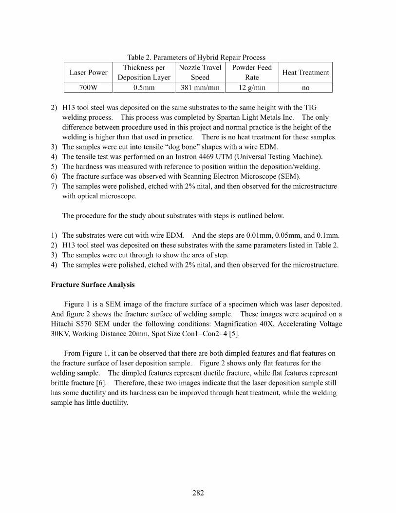
Table 2. Parameters of Hybrid Repair Process
Laser Power Thickness per Deposition Layer
Nozzle Travel Speed
Powder Feed Rate Heat Treatment
700W 0.5mm 381 mm/min 12 g/min no
2) H13 tool steel was deposited on the same substrates to the same height with the TIG welding process. This process was completed by Spartan Light Metals Inc. The only difference between procedure used in this project and normal practice is the height of the welding is higher than that used in practice. There is no heat treatment for these samples.
3) The samples were cut into tensile “dog bone” shapes with a wire EDM. 4) The tensile test was performed on an Instron 4469 UTM (Universal Testing Machine). 5) The hardness was measured with reference to position within the deposition/welding. 6) The fracture surface was observed with Scanning Electron Microscope (SEM). 7) The samples were polished, etched with 2% nital, and then observed for the microstructure
with optical microscope.
The procedure for the study about substrates with steps is outlined below.
1) The substrates were cut with wire EDM. And the steps are 0.01mm, 0.05mm, and 0.1mm. 2) H13 tool steel was deposited on these substrates with the same parameters listed in Table 2. 3) The samples were cut through to show the area of step. 4) The samples were polished, etched with 2% nital, and then observed for the microstructure.
Fracture Surface Analysis
Figure 1 is a SEM image of the fracture surface of a specimen which was laser deposited. And figure 2 shows the fracture surface of welding sample. These images were acquired on a Hitachi S570 SEM under the following conditions: Magnification 40X, Accelerating Voltage 30KV, Working Distance 20mm, Spot Size Con1=Con2=4 [5].
From Figure 1, it can be observed that there are both dimpled features and flat features on the fracture surface of laser deposition sample. Figure 2 shows only flat features for the welding sample. The dimpled features represent ductile fracture, while flat features represent brittle fracture [6]. Therefore, these two images indicate that the laser deposition sample still has some ductility and its hardness can be improved through heat treatment, while the welding sample has little ductility.
282
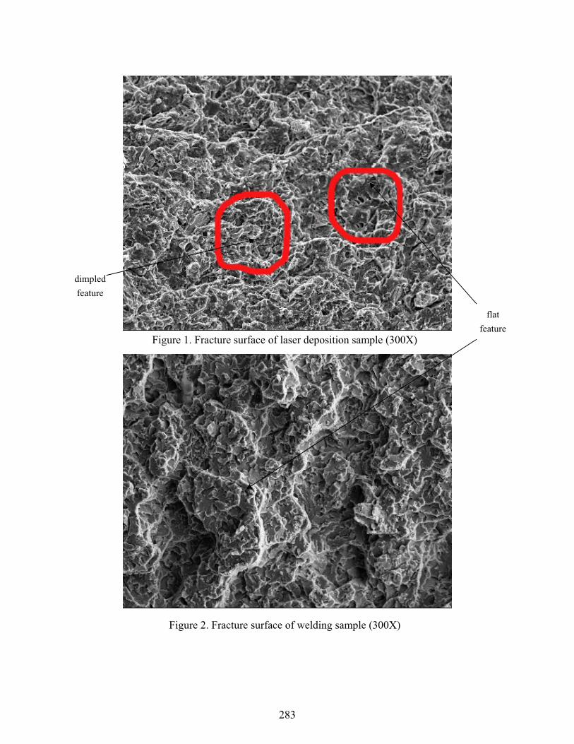
Figure 1. Fracture surface of laser deposition sample (300X)
Figure 2. Fracture surface of welding sample (300X)
dimpled feature
flat feature
283
Microstructure Comparison
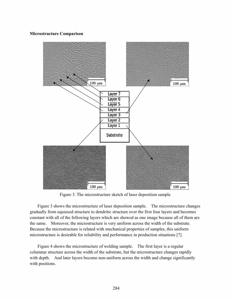
Figure 3. The microstructure sketch of laser deposition sample
Figure 3 shows the microstructure of laser deposition sample. The microstructure changes gradually from equiaxed structure to dendritic structure over the first four layers and becomes constant with all of the following layers which are showed as one image because all of them are the same. Moreover, the microstructure is very uniform across the width of the substrate. Because the microstructure is related with mechanical properties of samples, this uniform microstructure is desirable for reliability and performance in production situations [7].
Figure 4 shows the microstructure of welding sample. The first layer is a regular columnar structure across the width of the substrate, but the microstructure changes rapidly with depth. And later layers become non-uniform across the width and change significantly with positions.
284
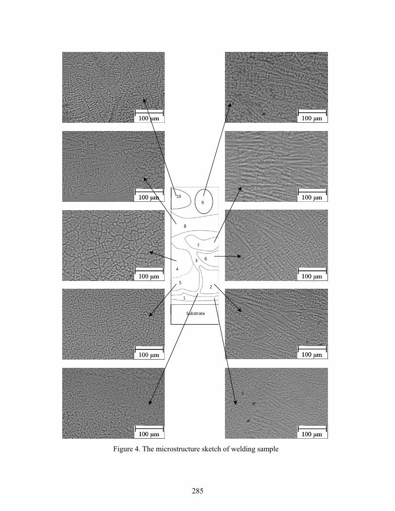
Figure 4. The microstructure sketch of welding sample
285
This non-uniform microstructure is caused by different cooling rate at different areas. The nature of the manual arc welding process induces some randomness into the weld. This makes the reproducibility and performance of the repair unsatisfactory.
Comparison Between Deposition on Substrates with Different Steps
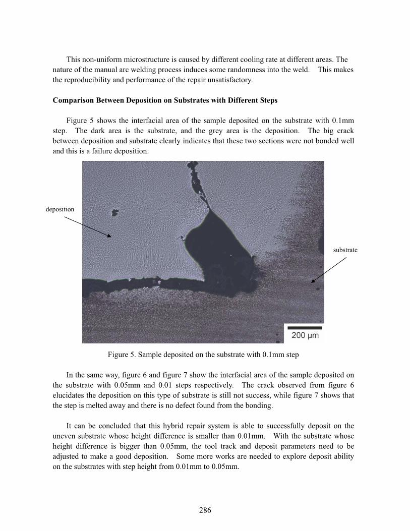
Figure 5 shows the interfacial area of the sample deposited on the substrate with 0.1mm step. The dark area is the substrate, and the grey area is the deposition. The big crack between deposition and substrate clearly indicates that these two sections were not bonded well and this is a failure deposition.
Figure 5. Sample deposited on the substrate with 0.1mm step
In the same way, figure 6 and figure 7 show the interfacial area of the sample deposited on the substrate with 0.05mm and 0.01 steps respectively. The crack observed from figure 6 elucidates the deposition on this type of substrate is still not success, while figure 7 shows that the step is melted away and there is no defect found from the bonding.
It can be concluded that this hybrid repair system is able to successfully deposit on the uneven substrate whose height difference is smaller than 0.01mm. With the substrate whose height difference is bigger than 0.05mm, the tool track and deposit parameters need to be adjusted to make a good deposition. Some more works are needed to explore deposit ability on the substrates with step height from 0.01mm to 0.05mm.
deposition
substrate
286
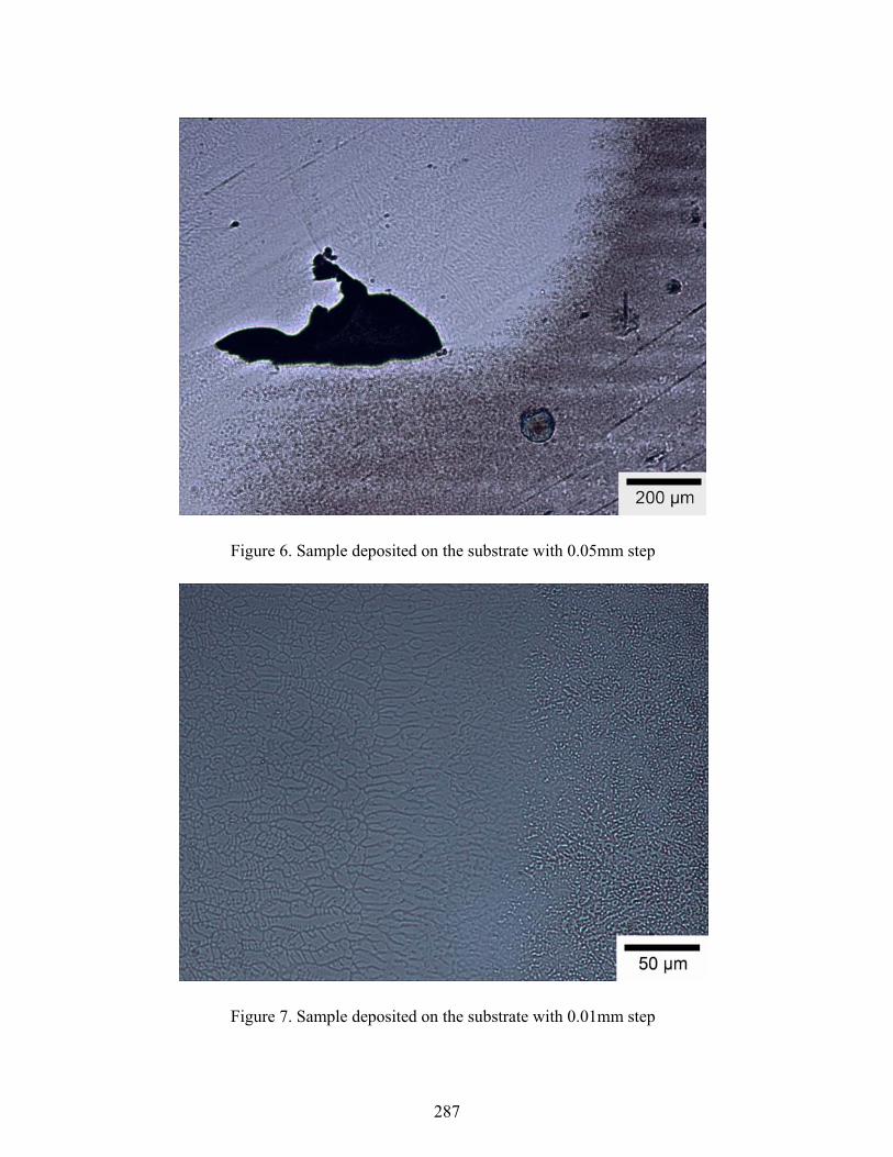
Figure 6. Sample deposited on the substrate with 0.05mm step
Figure 7. Sample deposited on the substrate with 0.01mm step
287
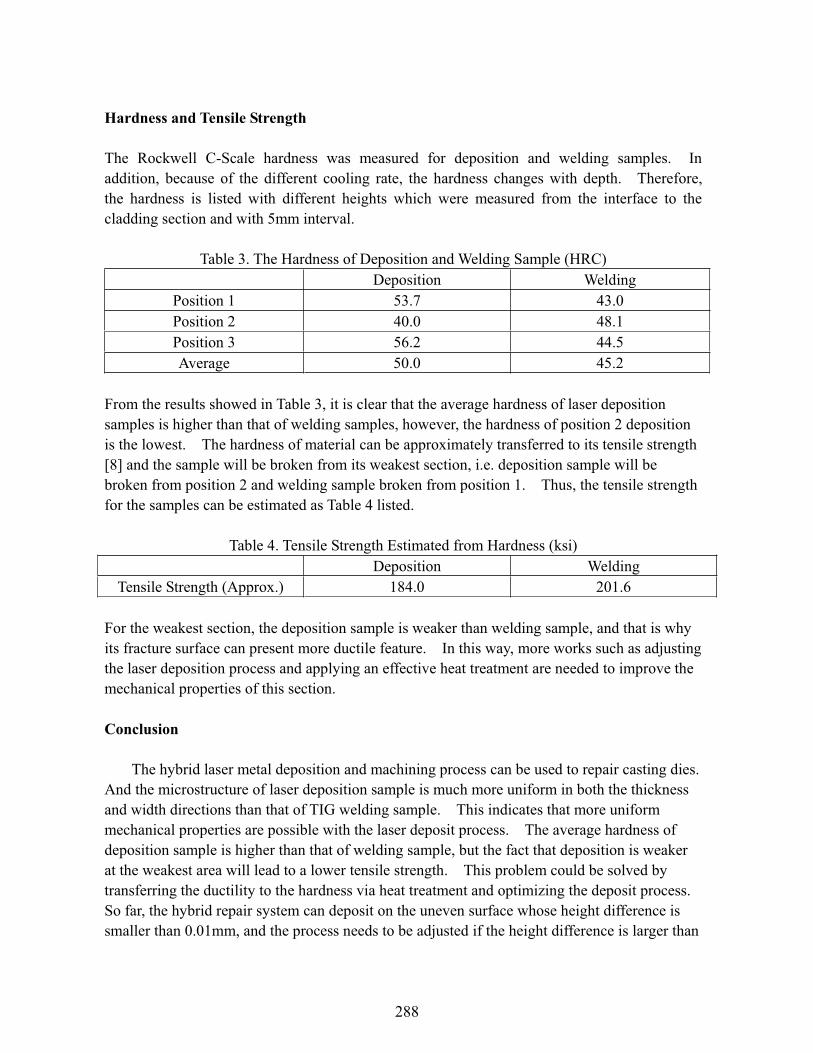
Hardness and Tensile Strength
The Rockwell C-Scale hardness was measured for deposition and welding samples. In addition, because of the different cooling rate, the hardness changes with depth. Therefore, the hardness is listed with different heights which were measured from the interface to the cladding section and with 5mm interval.
Table 3. The Hardness of Deposition and Welding Sample (HRC) Deposition Welding
Position 1 53.7 43.0 Position 2 40.0 48.1 Position 3 56.2 44.5 Average 50.0 45.2
From the results showed in Table 3, it is clear that the average hardness of laser deposition samples is higher than that of welding samples, however, the hardness of position 2 deposition is the lowest. The hardness of material can be approximately transferred to its tensile strength [8] and the sample will be broken from its weakest section, i.e. deposition sample will be broken from position 2 and welding sample broken from position 1. Thus, the tensile strength for the samples can be estimated as Table 4 listed.
Table 4. Tensile Strength Estimated from Hardness (ksi) Deposition Welding
Tensile Strength (Approx.) 184.0 201.6
For the weakest section, the deposition sample is weaker than welding sample, and that is why its fracture surface can present more ductile feature. In this way, more works such as adjusting the laser deposition process and applying an effective heat treatment are needed to improve the mechanical properties of this section.
Conclusion
The hybrid laser metal deposition and machining process can be used to repair casting dies. And the microstructure of laser deposition sample is much more uniform in both the thickness and width directions than that of TIG welding sample. This indicates that more uniform mechanical properties are possible with the laser deposit process. The average hardness of deposition sample is higher than that of welding sample, but the fact that deposition is weaker at the weakest area will lead to a lower tensile strength. This problem could be solved by transferring the ductility to the hardness via heat treatment and optimizing the deposit process. So far, the hybrid repair system can deposit on the uneven surface whose height difference is smaller than 0.01mm, and the process needs to be adjusted if the height difference is larger than
288
0.05mm.
Acknowledgement
This research was supported by the National Science Foundation Grant Number DMI-9871185, the grant from the U.S. Air Force Research Laboratory contract # FA8650-04-C-5704, and UMR Intelligent Systems Center. Their support is greatly appreciated. The author also wishes to express his gratitude to: Spartan Light Metal Products Inc. Mr. Max Vath, Rolla Technology Institute Mr. Jeff Thomas, Interdisciplinary Engineering at University of Missouri-Rolla
References
[1] Eiamsa-ard, Kunnayut , Hari Janardanan Nair, Lan Ren, Jianzhong Ruan, Todd Sparks, and Frank W. Liou, "Part Repair using a Hybrid Manufacturing System", Proceedings of the Sixteenth Annual Solid Freeform Fabrication Symposium, Austin, TX, August 1-3, 2005.
[2] Deepak G. Bhat, Francis F. Williams, “Hard Wear Resistant Coatings for Die-Casting Dies by an Advanced Filtered Cathodic Arc Deposition Process”
[3] R.E. Smallman, R.J. Bishop, Modern Physical Metallurgy & Materials Engineering,Butterworth-Heinemann, 1999
[4] Jianzhong Ruan, Kunnayut Eiamsa-ard, and F.W. Liou, “Automatic Process Planning and Toolpath Generation of a Multiaxis Hybrid Manufacturing System”, Journal of Manufacturing Processes Vol. 7/No. 1 (2005) 57-66
[5] Goldstein, Joseph, et al., Scanning Electron Microscopy and X-Ray Microanalysis, Kluwer Academic/Plenum Publishers, 2003
[6] Donald R. Askenland, Pradeep P. Phule, Essentials of Materials Science and Engineering,Thomson Engineering, 2004
[7] Mazumder, J., J. Choi, K. Nagarathnam, J. Koch and D. Hetzner, (1997) "Direct Metal Deposition Of H13 Tool Steel for 3-D Components: Microstructure and Mechanical Properties", Journal of Metals, 49 (1997) 55-60.
[8] eFunda, Convert Hardness: Rockwell C-Scale, retrieved from http://www.efunda.com/units/hardness/convert_hardness.cfm?HD=HRC&Cat=Steel#ConvInto
289